

Page 1

R
R
Installations- und Betriebsanleitung
GERMANY
C
C
GERMANY
By selecting this VC product you have chosen a professional
device, which guarantees highest possible quality and
Please read the following instructions carefully before
comissioning the product in order to be able to take full
advantage of all quality features regarding this product line.
Mounting and Operating Manual
Dear Customer!
reliability.
Digital Video Recorder
Art. no. 11564
© All contents of this document may change without prior notice
Änderungen in Technik, Design und Ausstattung vorbehalten
VC-videocomponents.... aligned for professional videosystems
MO_11564/16.09.2011
MO_14511-K
Page 2

1
Page 3
Copyright Notice
Information in this document is subject to change without notice. Our company may make
improvements or changes in this manual and CMS Software if necessary. The software, which
includes the information contained described in this document is furnished under a license agreement
and may be used or copied only in accordance with the terms of the agreement. It is against the law of
copyright to duplicate the software except as specifically allowed in the license agreement. No part of
this manual may be reproduced or transmitted in any form or by any means, including photocopy or
duplicate, for any purpose without prior written permission by our company.
This device complies with Part 15 FCC Rules. Operation is subject to the following two conditions:
(1) This device may not cause harmful interference.
(2) This device must accept any interference received including interference that may cause undesired
operation.
Safety Instructions
Warnings & Cautions
Please read the following safety warnings and keep this manual in a place which you can read
whenever you need.
1. Keep the Video Servers away from water, wet, hot, flammable area or with heavy moisture
2. Check the existing electric environment if it’s applicable (90V~240V AC) before use
3. Avoid to operate it in high temperature environment
4. Please put the Video Server and Hub in a flat stable place to operate
5. Do not disassemble the product arbitrarily.
W
A
R
N
I
A
A
A
U
U
U
R
R
N
N
I
N
N
I
N
T
I
O
T
I
O
T
I
O
W
W
C
A
C
A
C
This symbol indicates that personal injury may occur or the product may be
damaged when you fail to follow the given instruction
This symbol indicates that property loss may occur or the product may
NN
N
malfunction when you fail to follow the given instruction
2
Page 4
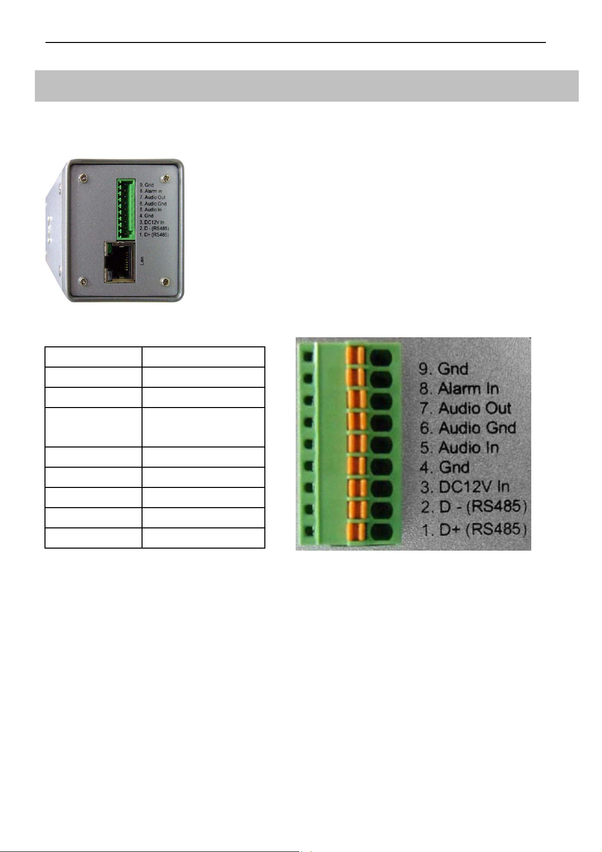
Network IP Cameras
nCam Series: 2M/ High-Resolution CCD
Product Front View Product Rear View
9. Gnd Gnd
8. Alarm In Alarm In
7. Audio Out Alarm Out
6. Audio Gnd Audio Gnd (for audio
in & out)
5. Audio In Audio In
4. GND GND
3. DC12V In DC12V In
2. D-(RS485) RS485 (D-)
1. D+(RS485): RS485 (D+)
Notes:
* For nCam Series cameras, the power is provided via POE by Gigabit POE HUB. Thus, it is not
necessary to connect the DC12V In (pin-3) and Gnd (pin-4) from the above illustration.
* Please use the CAT-6 LAN cable to connect each Telexper devices.
* The effective distance away from the nHub-4P POE Hub is 100 meters.
3
Page 5

Properties
2M/ High-Resolution CCD
CMOS / CCD Sensors, H.264 Compression
Resolution 640x480 @30fps
720x480 @30fps
PoE(Power over Ethernet) Hub to feed power
Built-in mechanical IR Cut Filter
Built-in Fixed/Manual/Auto Lens
IR LED 30~36PCSIR distance: 20M
4 Motion detection in one image
Linux OS
H.264/M-JPEG SOC dual compression
4
Page 6
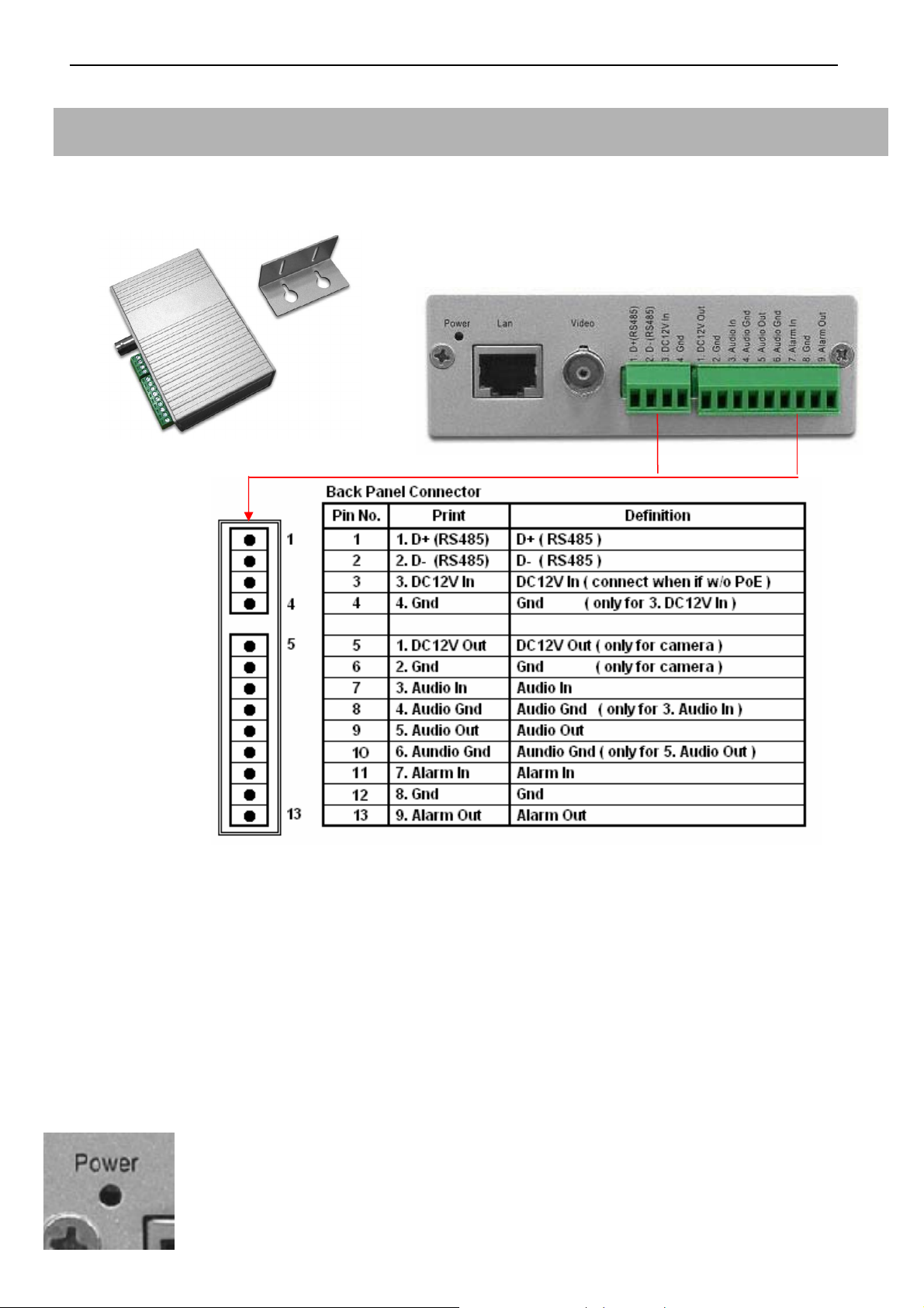
Video Server
Model: 11572
- Product Front View - Product Rear View
nVS-1P Back Panel Connector illustration
Notes:
* For nVS-1P, the power is provided via POE by Gigabit POE HUB. Thus, it is not necessary to
connect the DC12V In (pin-3) and Gnd (pin-4) from the above illustration.
* For nVS-1, nVS-1 doesn’t support the POE. Thus, please input the DC12V, 1.2A (min) electric
power in the DC12V In (pin-3) and Gnd (pin-4).
* Please use the CAT-6 LAN cable to connect each devices.
* Please use the 75 Ohm coaxial video cable connecting the camera and the video server.
* The DC12V Output at pin-5 provides the max 8W electric power.
* The nVS-1 Video Server requests the DC12V, 1.2A (min) electric power.
* The effective distance away from the nHub-4P POE Hub is 100 meters.
- The states of the Power LED
*
Red Color:
*
Red Flashiness:
Power on when connect with the nHub-4P (Gigabit POE HUB)
When the LAN is active
5
Page 7

Properties:
1. Upgrade any Traditional Analogue Camera to the IP System
2. H.264 & M-JPEG Dual-type Codec
3. De-centralized & Modularized Design
4. Unlimited Number of Camera Expansion at any time
5. No Power Cable to Camera Required
6. Reduce minimum 50% of Installation Cost
7. Less Maintenance Cost than Analogue System
8. Up to 30fps @D1, 120fps@CIF Display & Recording
9. Multi Video Audio Streaming Design
6
Page 8
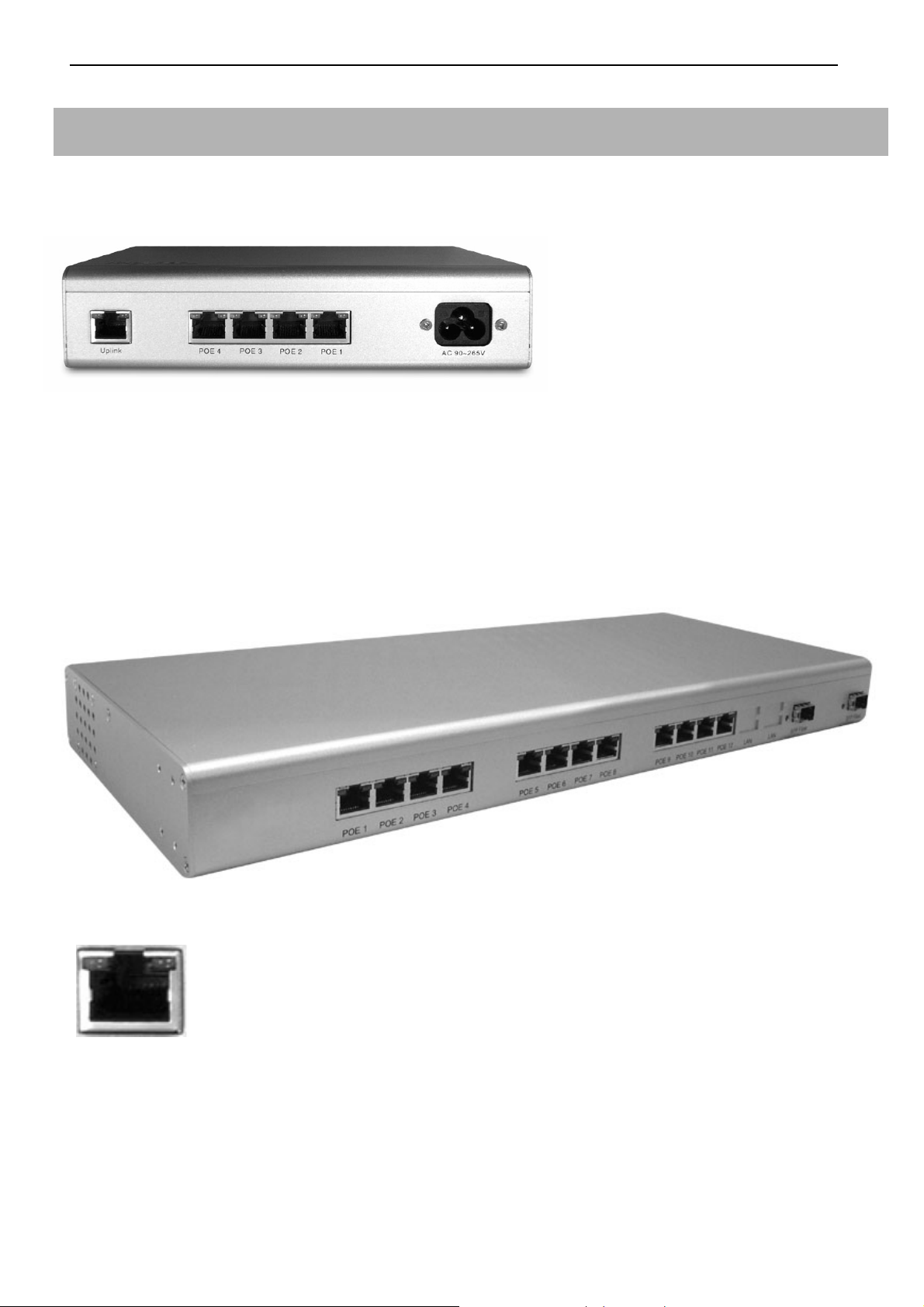
Gigabit POE HUB
Model: 11574
- Product Front View
- Uplink : 10/100/1000Base-TX uplink ports for connect with the Wan / LAN
- POE 1-4: 10/100/1000Base-TX with POE injectors
- AC Input: for connected with power cable (Range 90V – 265V)
Model: 11575
- Product Front View
- The states of the LED
* Double Green lights: Giga-LAN
* Left Orange + Right Green light: Mega-LAN
Notes:
Power Provision Max DC48V, 300mA per each port
7
Page 9
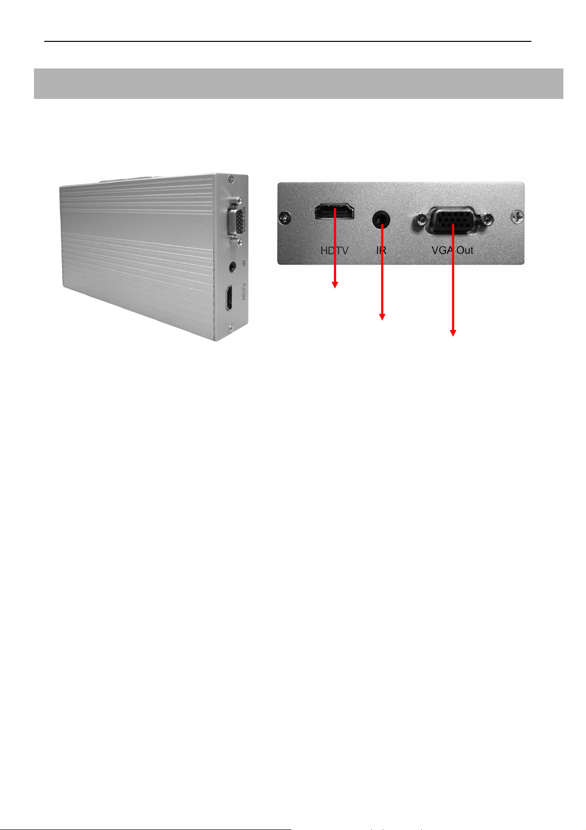
Network Video Decoder (Video Matrix)
Model: 11571
-
Product Front View
HDMI output
IR connector
VGA output
Embedded Linux Platform
- Product Rear View
Properties:
1. Provide H.264 video stream decode service.
2. VGA (D-SUB) and HDMI video output connector.
3. Real-time image decode 30fps, could display by full screen and quad screen.
4. High resolution D1 or CIFx4.
5. Support POE function.
6. CMS could provide monitoring, sequence display, alarm display, and etc functions.
7. Could work independently with only cameras, with or without CMS server.
8
Page 10
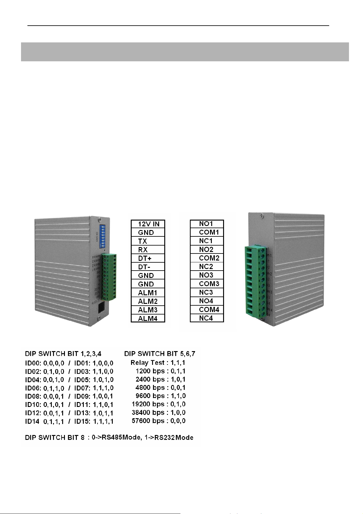
RS485 Controller
Product Description
Each device provides the Video Server additional 4 set of the control unit, could use to connect 4
different alarm input and out-put devices.
Installation
Please connect the RS485 controller DT+ (D+) pin to the D+ pin of the Video Server, and also the
DT-(D-) pin to the D-pin of the Video Server. The power could provide from the 12V OUT pin of the
Video Server, and make sure both of the GND pin connected well to enable the power supply.
Model: 11573
-
Product Front View
DIP Switch adjust table: BIT1~4 for ID, BIT5~7 for Baud Rate, BIT8 for transmission mode.
Properties:
-
Product Rear View
1. Require the DC12V, 350mA input.
2. Provide the additional 4 set of alarm input and alarm output.
9
Page 11
Network Video Recorder
Installation
Connect the nVR to the CMS network; the CMS system will auto detect the nVR devices without any
additional configuration.
Record Function
Add the cameras which need to be recorded by nVR, each nVR works independently.
Playback Function
Playback the video films with CMS.
Model: 11560 / 11561
- Product Front View
11560
Embedded XP Platform
Properties:
1. Support All Analogues Camera with Video Server
2. Dual-type Codec (H.264 + JPEG)
3. Dual-Monitor Display Design (Video + E-Map)
4. Pentaplex Design (Live, REC, Playback, Backup, Remote Viewing)
11561
5. Hot-standby REC (Always Recording)*1
6. Smart Motion Activity Search
7. E-mail Alarm (inc HDD Failure) Notification
8. CD or/ DVD Burner Backup (optional)
9. Dynamic & Static IP supported
10. Remote Viewing via 3G handset *2
11. Up to 25,600 cam CMS available
Notes: 1. Deduct the dead possibility caused by hard disk failure
2. Support "Windows Mobile OS" 3G Handset ONLY
To avoid the risk of explosion from using incompatible battery, please use batteries
with the same specifications or recommended by your original supplier or
manufacturer. Dispose of used batteries according to the instructions.
10
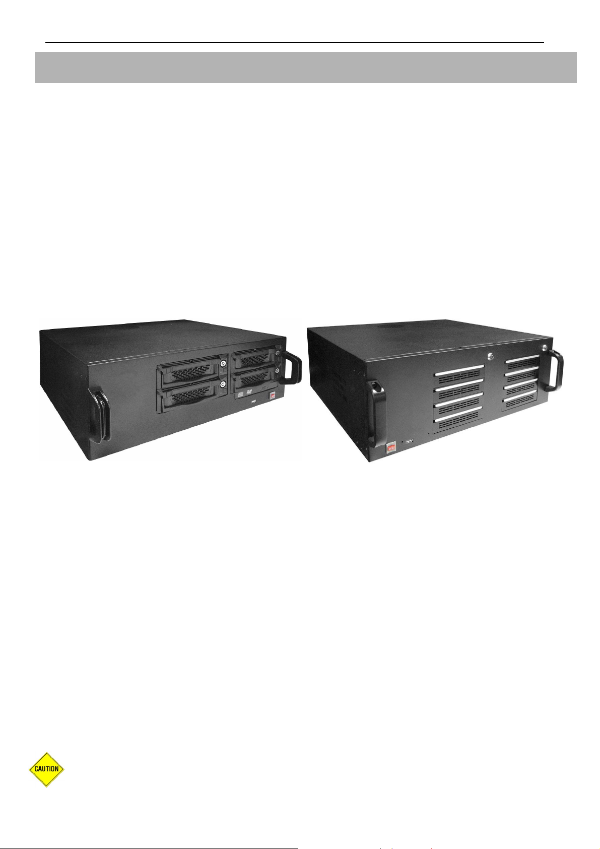
Page 12
Model: 11562 / 11563 RAID
- Product Front View -Product Rear View
Embedded XP Platform
Features:
1. XP Embedded OS
2. SATA I, SATA II Hard Drive
3. Auto Partition Allocation
4. Duplex Operation
5. Compatible with VGA, D1, 1.3Mega, 2Megapixel IP Cameras
6. TMSP*1 Protocol Protection Gives Security Data Leak FREE
7. RAID 0 / 1 / 5, Hot Swap
8. 19" Rack Mountable Housing
9. Support up to 64 channels/cameras video recording.
10. Dual Power Redundant
Notice: For nVR-15RAID series, don’t use GreenPower hard disk series. We recommend to use
Seagate hard disk.
11
Page 13
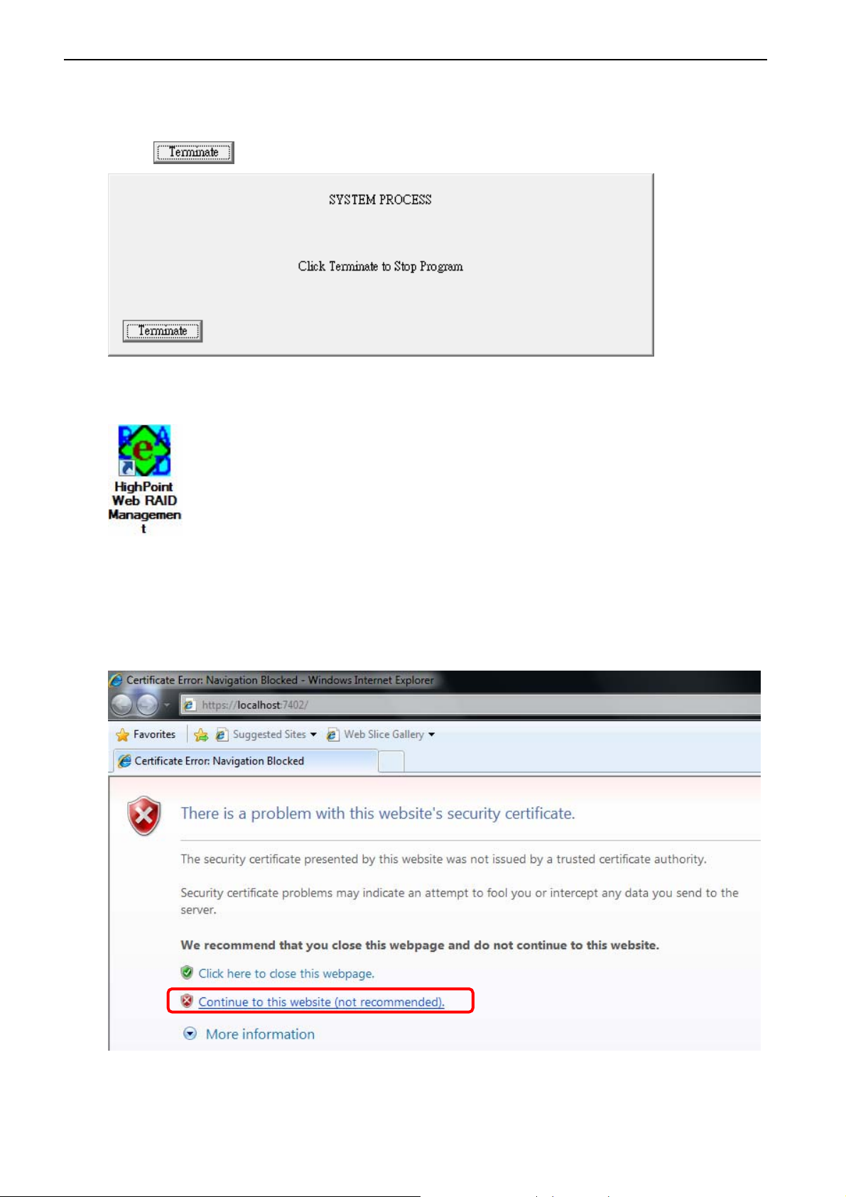
nVR RAID 5 Setup Guide
1. Insert HDD to NVR and restart the system. A pop-up window (see picture below) will appear.
Click to stop the program.
2. On your system desktop, double-click
.
HighPoint Web RAID Management
shortcut
3. Internet Explorer will be initiated automatically. Please select “Continue to this website (not
recommended)”to continue to the main page of
HighPoint Web RAID Management
.
12
Page 14
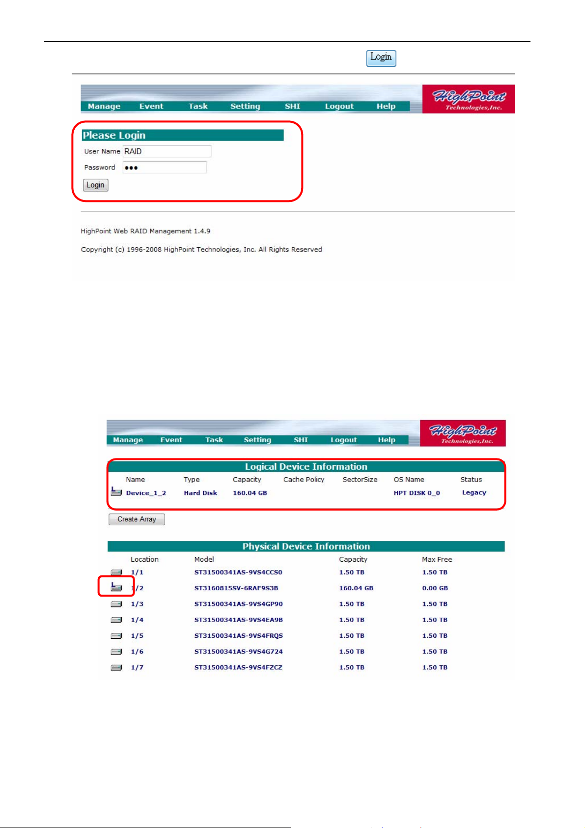
4. Enter User Name: RAID, Password: hpt, and then click .
5. After log in successfully, you will see
Ensure the quantity of HDD is correct. If not, please turn off the system to check whether
HDDs were inserted properly or were defective.
Under
Physical Device Information
the HDDs from the HDD icon. HDD icon with letter L (Legacy) on it is for used HDD.
HDD icon without any letter is for new HDD.
Logical Device Information
page.
section, you can distinguish the new/used status of
13
Page 15
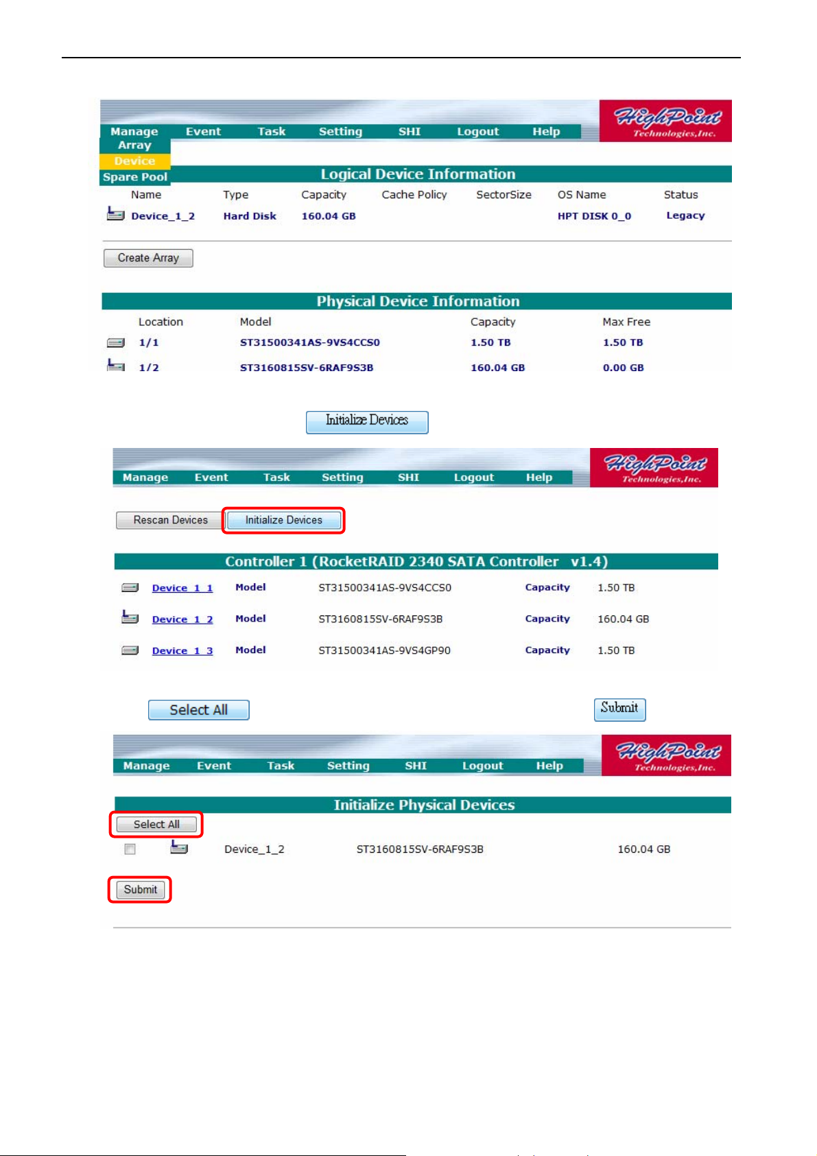
6. After checking the HDD Status, go to
Manage
, then select
Device
.
7. Under
8. Click
Manage
page, click to enter
Initialize Physical Device
to select all un-initialized HDD, and then click to start.
page.
14
Page 16
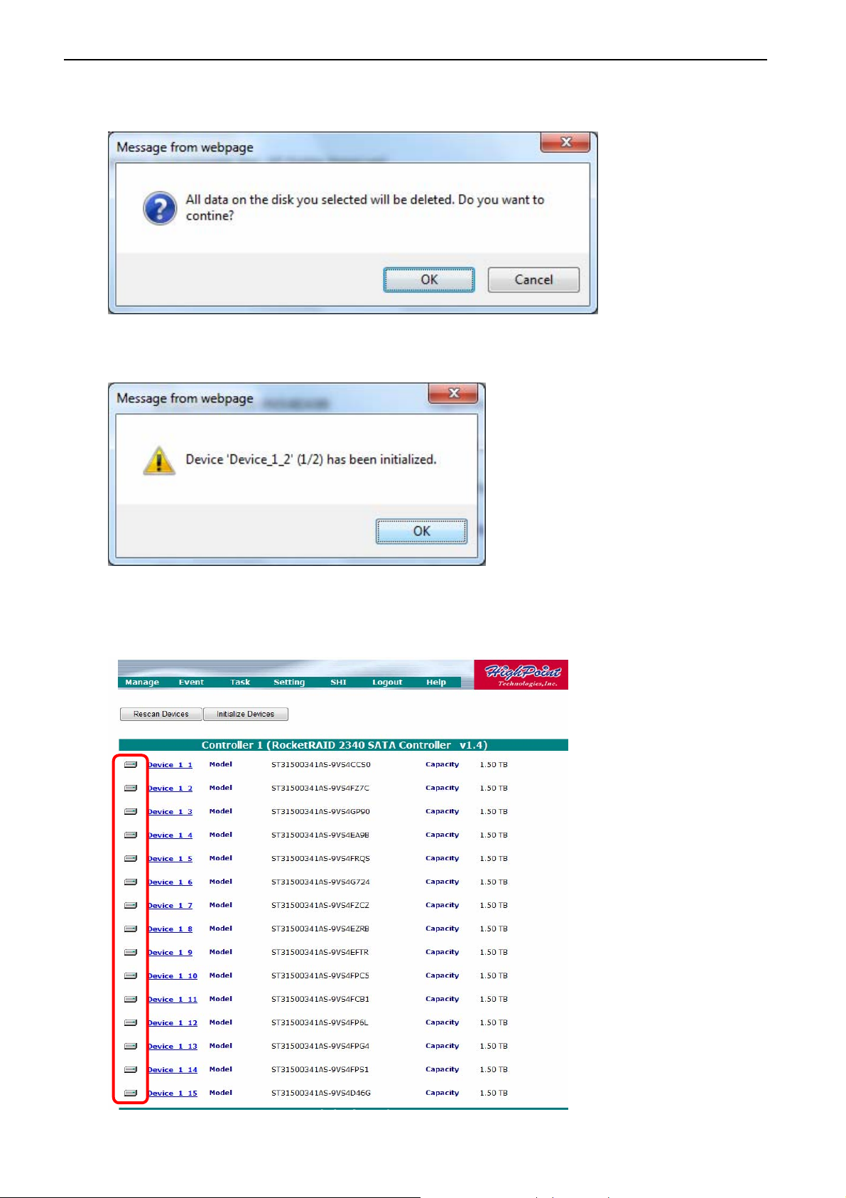
9. Click OK on
“All data on the disk you selected will be deleted. Do you want to
continue?”
10. System will message you for every completion of each HDD.
11. After completion of HDD initializing, there will be no letter on the HDD icons on the
Device Information
.
Physical
15
Page 17
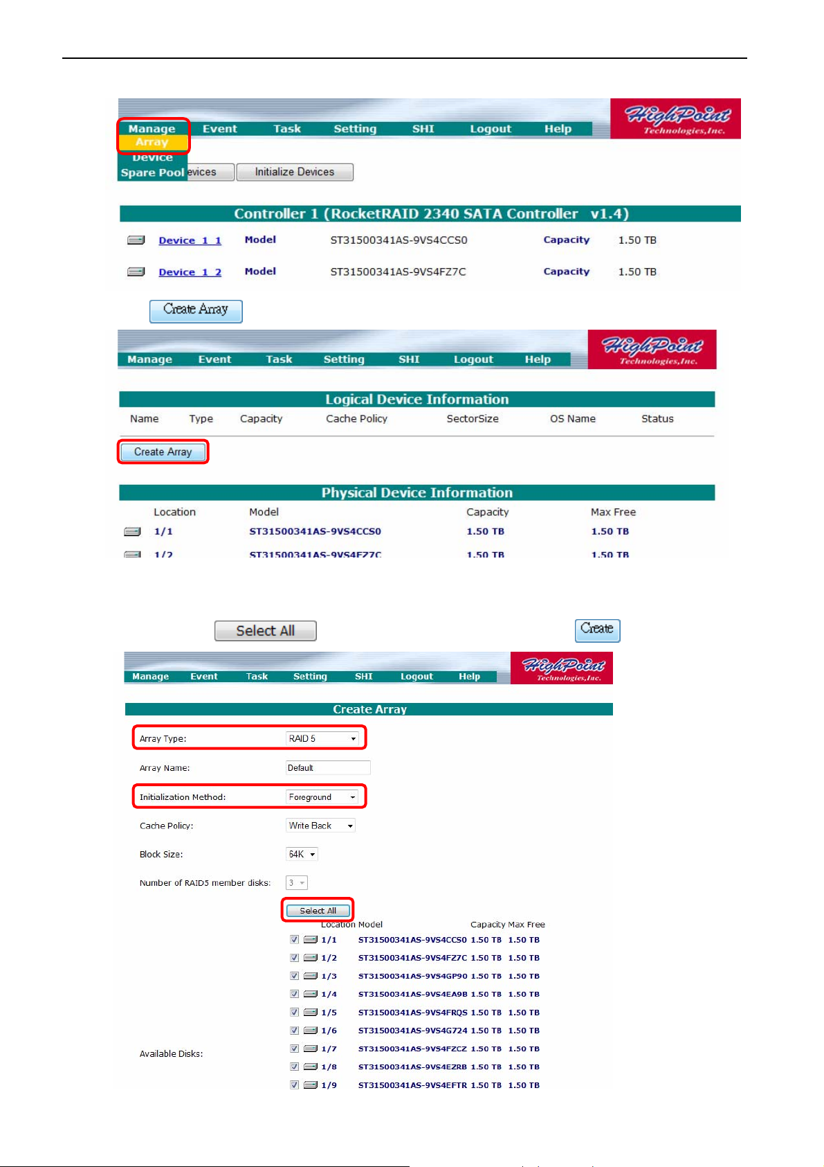
12. Go to
Manage
and select
Array.
13. Click to enter
14. Under
Create Array
Method. Click to select all HDDs, and then click to begin.
Create Array
page, select
RAID 5
Page.
for Array Type,
Foreground
for Initialization
16
Page 18
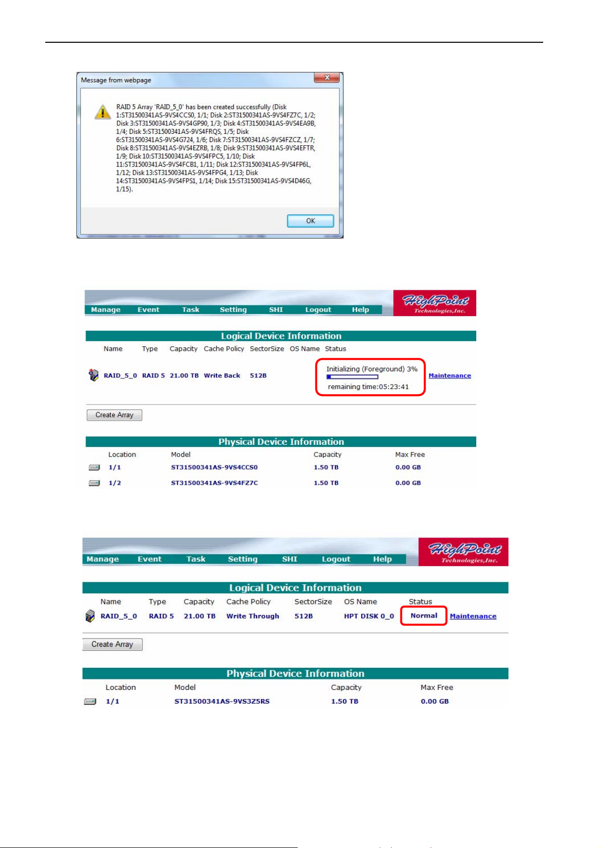
15. A message will appear upon completion.
16. Initialization process will begin upon array creation.
17. Upon initialization process, the status will become
Normal
.
18. Please restart the system.
17
Page 19
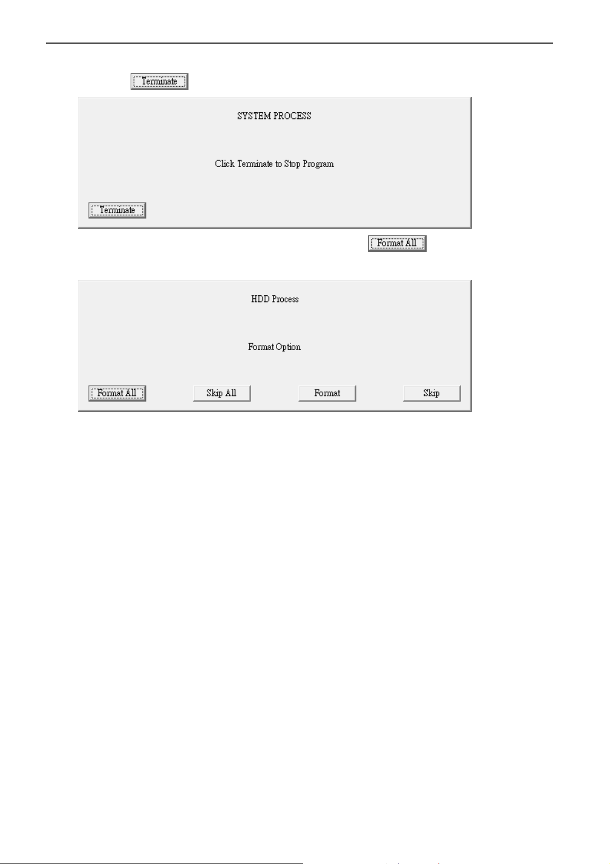
19. When you restart the system, the
click and wait 30 seconds for this window to disappear.
not
System Process
window will appear. This time, please
20. The system will ask for HDD formatting. Please click to begin HDD formation
process.
do
21. Upon HDD formation, the system will automatically restart again and start NVR program.
Notice: If the network video recorder is nVR-15 or nVR-15 RAID series, please insert the HDD
rack from left bottom to the right top, in order to prevent no detection of HDD.
18
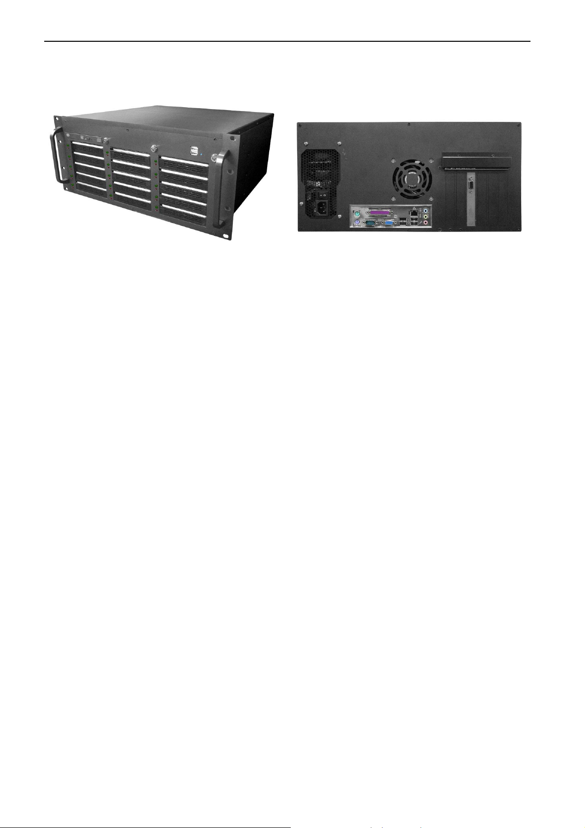
Page 20
Commander Station (Central Management Server software built-in)
Model: 11564 bis 11570
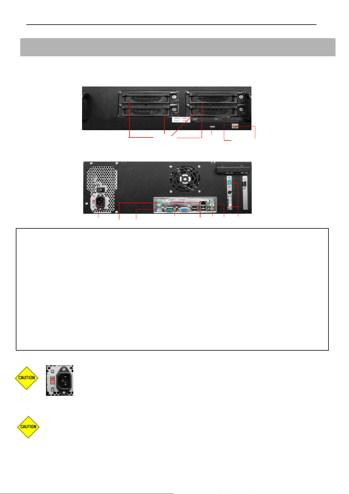
- Product Front View
4 3 2 1
- Product Rear View
12 11 10 9 8 7 6 5
Item Component Description
1 Power button Press to turn the nCS on.
2
3 USB port Plug USB devices.
4 HDD Caddy * 4 For HDD installation.
5 Video Out Video output connector for Monitors.
6 Speaker Out Plug an external speaker into this jack to listen voice.
7 Mic In Plug an external microphone into this jack to transmit voice.
8 USB ports * 4 Plug USB devices.
9 Ethernet Jack Plug 10/100/1000 Ethernet network cable into the jack.
10 Keyboard Plug the keyboard.
11 Mouse Plug the Mouse.
12 Power In jack Plug the power cord into the port.
Recordable DVD
Drive
Default manufacturer setting is set to 230V.
If the environment is under the 115V electric power supplied.
Use this drive to install programs, store files onto recordable
DVDs.
Please ensure to use the correct voltage 115V before turning on the nCS.
To avoid the risk of explosion from using incompatible battery, please use batteries
with the same specifications or recommended by your original supplier or
manufacturer. Dispose of used batteries according to the instructions.
19
Page 21

System Requirements for the LVC and RemoteCMS Software
IP CCTV Solution provides the best performance, stability and reliability for you all to have the best
quality on the Surveillance and security.
Regarding the LVC (Local View Client), or RemoteCMS, please refers to the Recommended
Hardware Environment as below.
Minimum Computer Requirements for LVC (Local View Client) and RemoteCMS:
- Operating System: Better to have the Windows XP SP2 at least or most updated patch
- CPU: Intel Dual-Core 2.66GHz, or higher
- Ram: 2GB Memory or more
- HDD: Minimum 300MB space size for software application installation
- Display: Best Recommended Resolution at 1680x1050
Recommended Computer Requirements for LVC (Local View Client) and RemoteCMS:
- Operating System: Better to have the Windows XP SP2 at least or most updated patch
- CPU: Intel Core2 Quad 2.66 GHz, or higher
- Ram: 4GB Memory or more
- HDD: Minimum 300MB space size for software application installation
- Display: Best Recommended Resolution at 1680x1050
20
Page 22

Chapter 1System Setup
)
Chapter 1 System Setup
System Setup Flow Chart
Prepare the hard disks (HDD)
3.5 SATA type HDD is recommended
Install the HDDs inside the Caddy case
(For nCS series, ensure to lock the
HDD power switch
Connect Cameras by using the 75 Ohm
coaxial video cable to nVS-1P
Connect the nVS-1P by using the CAT-6
LAN cable to nHub-4P
Connect the nHub-4P by using the
CAT-6 LAN cable to nCS
Check the Monitors, Keyboard, Mouse,
Power on the nCS, the system
would auto-setup at first launch
CMS will start after 3-5 times reboot
Finish, system start working
21
Page 23

System Setup
Setup under Firewall Environment
Among the anti-virus products in the market, many have the firewall feature included. If your IP
Network devices were installed under the environment with firewall, you will need to manually open
ports to allow CMS system to detect ALL the IP devices.
1. Ensure port numbers are opened.
Required port numbers for IP Network System:
Purposes Port Number
Central Commander Station, Hybrid DVR 6741
IP cameras, video servers, matrix decoders, NVR (network video
34000
recorder)
Remote CMS (Remote playback of WinNVR) 6742
Web service for CMS 80
2. If you were still not able to detect IP devices after opening all ports listed above, please shut
down your firewall or anti-virus software.
3. If you were able to detect all devices after closing down the anti-virus software or firewall,
please check and adjust your firewall or anti-virus software settings accordingly.
22
Page 24
Chapter 1System Setup
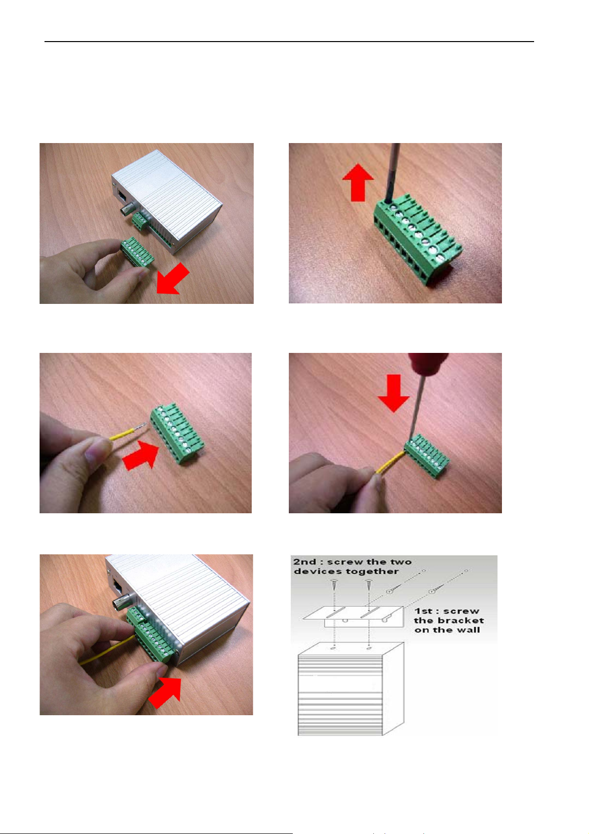
Quick Installation
Model: 11572
Step-1 Step-2
Step-3 Step-4
Step-5 For the Wall-mount bracket
23
Page 25
System Setup
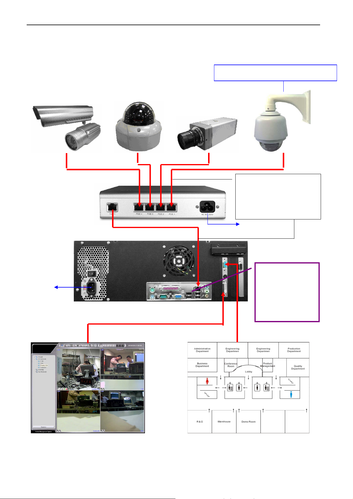
IP CCTV Installation Diagram
For the assembly of the speed dome camera, please refer to the complete manual.
Connect AC 100V or AC24V
Connect the nCAM
Power Cord
using the CAT-6
Ethernet cable to the
Power Cord
Connect the
nHUB-4P by
using the CAT-6
Ethernet cable
to nCS-16
24
Page 26
IP Address Setup (DeviceSetting)
Chapter 2 IP Address Setup (DeviceSetting)
IP Address Setup (DeviceSetting) software is designed specifically for user with complex internet
network to easily update each device’s network parameters.
Enter DeviceSetting
After installation from the Application CD, an icon will appear on the desktop.
Double-click the icon to begin the software.
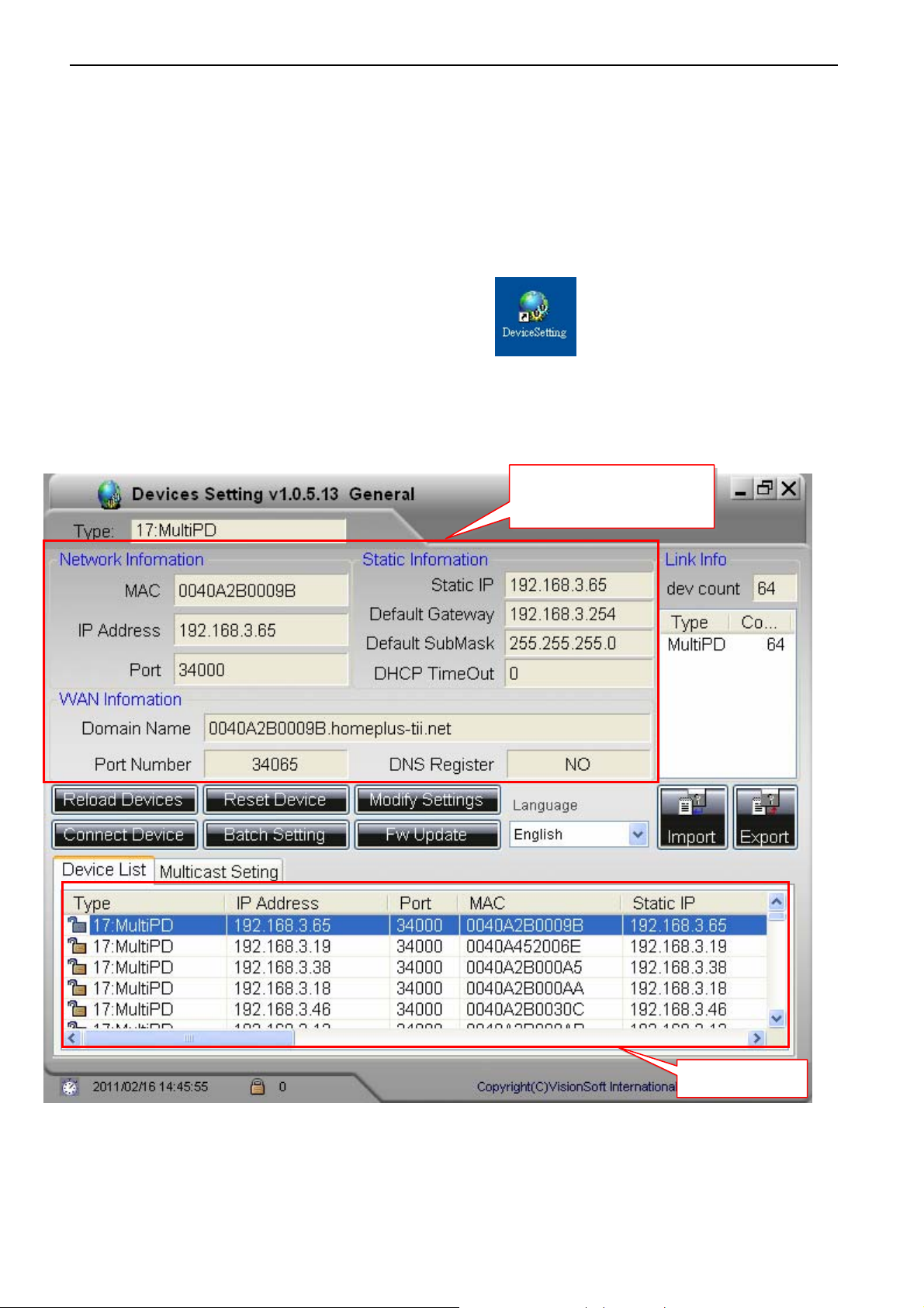
DeviceSetting—Main Menu
Current Device
Network Parameters
Device List
25
Page 27
IP Address Setup (DeviceSetting)
Current Device Network Parameters
Use the cursor to select one device from the Device List, then the information will display :
Type (e.g. 18: Video Server)
Network Information: Show the current MAC/ IP Address/ Port data of the selected device
Static Information: Show the current Static IP Address of the selected device
WAN Information: Show the current network parameters of the Dynamic IP network of the selected
device. Those parameters will be assigned by Telexper DNS servers automatically.
Domain Name: The Domain Name (e.g. 0040A250053C.homeplus-tii.net) is used to connect the device
remotely via WAN if the device is using the dynamic IP to WAN (internet)
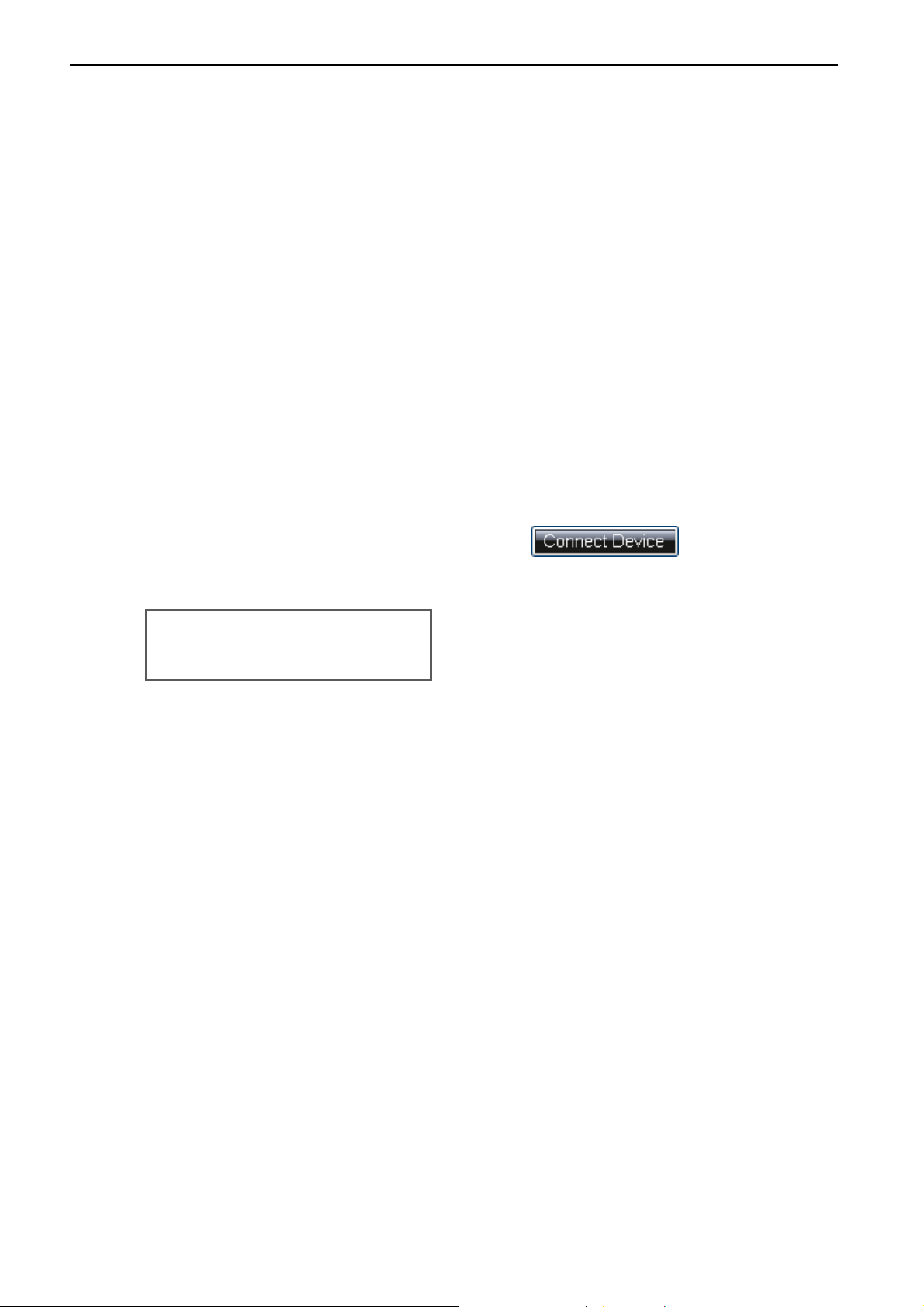
Buttons Descriptions
Connect Device
1. Select one device from the Device List and click to view directly.
2. User name and password are required:
Default Username: admin
Default Password: 99999999
26
Page 28
IP Address Setup (DeviceSetting)
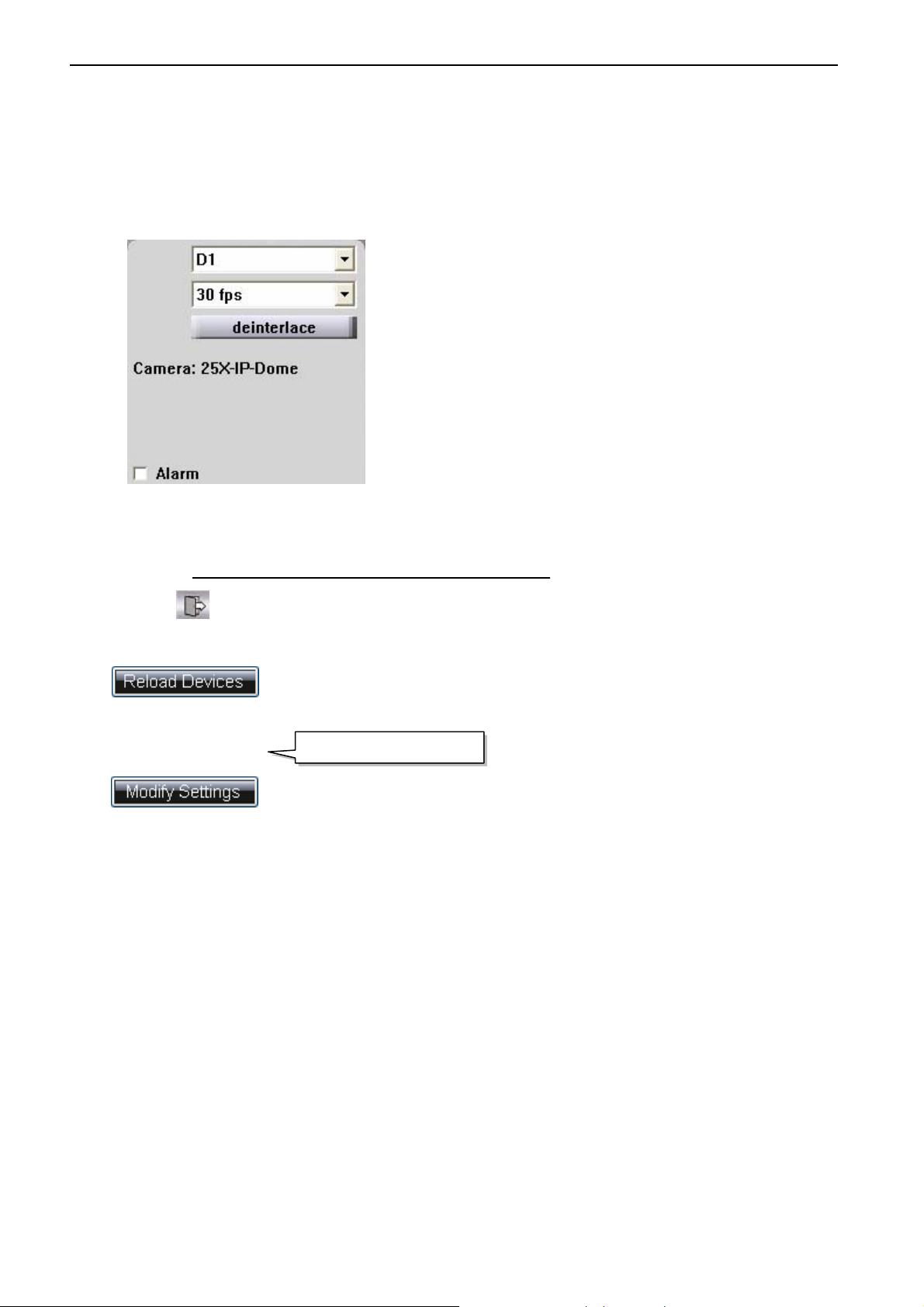
3. Once logged in, the live view will display as below. You may control the PTZ or I/O devices
by clicking on the small icons or right-clicking on the channel. The Snapshot function allows
user to save the current image as JPG file.
4. You may also adjust the device settings such as resolution and fps.
5. Check the Alarm box to enable alarm notification for Alarm-In-enabled device. When the
alarm is triggered, a red alarm icon will appear on the screen. For Alarm In setup, please
refer to Chapter 7—Alarm In and Alarm Out Setting.
6. Click to exit.
Reload Devices
Click
Modify Setting
Click button to edit selected device’s network information.
button to detect new devices and refresh current device list.
Device Control Icons
27
Page 29
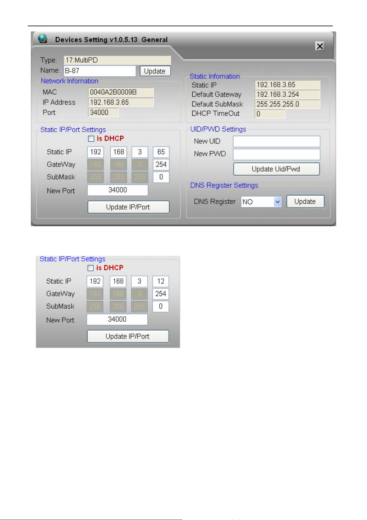
IP Address Setup (DeviceSetting)
Static IP/ Port Setting:
1. Uncheck is DHCP box to disable DHCP.
2.
Key in the assigned IP/ Port setting for the selected device.
3. Click Update IP/Port to save the settings.
28
Page 30

IP Address Setup (DeviceSetting)
User ID/ Password Setting:
Default Username: admin
DNS Server Registration Setting:
We have DNS servers located in different locations around the world to serve the customers at NO COST.
General Note for Device Setting:
1. Please ensure the device has been connected to the internet during this setup.
2. DNS server will assign a Domain Name & Port Number for you automatically; and show on the
main page as below.
3. It takes 20 to 30 seconds to upload the modified settings to the device. The background color
of device status list will become the color GRAY during uploading period; and back to WHITE
after completing the upload.
Reset Device
Click button to reset the network parameters of the selected device back to
default.
29
Page 31

IP Address Setup (DeviceSetting)
Batch Setting
This function enables user to synchronize multiple devices with the same settings at once. Using the
mouse and the
up page.
Control key
to select multiple devices and click
to enter the set
30
Page 32

IP Address Setup (DeviceSetting)
Firmware Update
Click to access to firmware update page. Another window will display the current
firmware of camera.
1
1. Select IP devices by checking the box for firmware update.
2. Click
3. Click to start updating.
to select file directory of firmware.
2 3
31
Page 33

CMS - General Operations
Chapter 3 CMS - General Operations
Getting Started CMS
Login CMS (Central Management Server Software)
Double-click the CMS shortcut icon to begin the software.
Then, there will be a window pop-up, key in username and password on it.
Default Username: admin
Default Password: 99999999
Press Keyboard button, the On-Screen Keyboard will be enable for input.
For the first-time login, CMS will detect automatically and display all cameras on the main screen.
After the first-time login, go to
new devices.
Setup
, click
Search
and
Refresh
to detect and update
32
Page 34

CMS - General Operations
Change the password of the user
Check on “
Change Password
”, the dialog window will expand.
Key-in the new password, and input again to confirm the new password, then, press “OK” to finish the
modification.
The “Change Password” function is also available in CMS-Setup Menu.
Please help to refer the
Chapter 7 CMS-Setup Menu
User Management.
33
Page 35

CMS - Main Menu (Live Mode)
A
Chapter 4 CMS - Main Menu (Live Mode)
For the first-time login, CMS will detect automatically and display all cameras on the main screen.
After the first-time login, go to
Main Menu Buttons
Devices Directory
Control Status:
-Audio In
-Audio Out
-PTZ
-Alarm In
-Alarm Out
Setup
, click
Search
and
Refresh
to detect and update new devices.
Current Date & Time
Screen Display
(4/8/9/10/13/16/25/36/64)
Alarm Status:
-Motion Alarm
-Sensor
larm
Status:
-LIVE
-REC
Sequence Buttons
Main Menu Buttons Overview
Camera Name
34
Page 36

CMS - Main Menu (Live Mode)
Playback
: Default mode for viewing the live view of the all camera channels
Live
: Switch to playback mode, please refer to
E-Map:
Monitor (TV Wall)
Enable the E-Map mode; please refer to
: Enable the Monitor mode, please refer to
Disable Alarm Notification:
Snapshot
Setup:
View Log
: Take a screen photo of currently selected camera screen.
Switch to the CMS Setup page. Please refer to the
: Open the log of System and Alarm list.
Playback Mode chapter.
E-Map Chapter
Monitor Chapter
Disable or enable the alarm sound.
CMS Setup
chapter
Alarm List
: List of the 50 latest alarm messages. Click on the highlighted event to
acknowledge the alarm.
Logout
Exit:
: Logout the current to switch to another log in user.
Close the CMS server system.
35
Page 37

CMS - Main Menu (Live Mode)
Hot Key
Alt + Enter: Switch the Camera display area to Full-Screen.
Camera Live Window
No Device
No Device picture appears when a camera device has not
been installed to this channel or the installed camera cannot
be detected by CMS.
Video Loss
Video Loss picture appears when there is a disconnection
between CMS and camera or the camera is broken.
36
Page 38

CMS - Main Menu (Live Mode)
Device Directory
All Cameras: It will show all cameras which are auto-detected by the CMS.
Click on the camera icon to view live video display on the right side.
Right-Click the mouse button on the camera will allow you to
setup the camera.
All NVR: It will show all the NVR (Network Video Recorder) devices which are
auto-detected by the CMS.
Right-Click the mouse button on the NVR will allow you to reboot or
shutdown the NVR.
All Monitors: It will show all the monitor devices which are auto-detected by the
CMS.
Except the directories tree of auto-detected devices, the system allows you to
create your own device groups* to manage all the devices on the system.
For device group settings, please refer to the Chapter 7 CMS – Setup Menu.
* All Cameras does not count as a group. Only the customer defined groups can start up the Monitor
(TV Wall) function. .
*All Cameras only shows all the cameras which were auto-detected by CMS system.
Sequence
Sequence rotates and plays camera groups in every designed time frame.
1. Click Sequence, check boxes of the group you wish to play, and then select the time interval
(5-60sec/min/hr).
2. Click Start Sequence to start or click Exit to cancel.
3. Click Stop Sequence to return to normal live view.
37
Page 39

CMS - Main Menu (Live Mode)
Screen Display
Supports the 4/8/9/10/13/16/25/36/64 display (CMS Lite version supports 16 display, Hybrid
16 version supports 36 display, Hybrid 32 version supports 64 display)
For Full-Screen Display, please help to click directly on the desired channel to select, and then
click again to switch to full-screen. Click again to return to the previous screen display.
Hide Cameras on the Live Screen
Drag and drop one channel to the Camera Directory to remove channels from the live screen.
There are two ways to include the channel back to the live screen:
1. Double-click the camera icon on the Camera Directory.
2. Drag and drop the icon back to the live screen.
Organize Cameras on the Live Screen
Drag a channel and drop it on the position on the live screen to re-organize the order of the
channels.
38
Page 40

CMS - Main Menu (Live Mode)
Shortcut to Device Settings, PTZ
Moves the mouse to the camera picture, then presses down the mouse right key to choose " Settings",
then may enter the camera directly the setting menu; enlarges after the camera picture, presses down
the mouse right key to chooses "Move Image", then may adjust the picture's display area horizontally,
press down a time mouse right key then to cancel the towing again.
PTZ Icon
Please ensure the
PTZ Protocol: Support Pelco_P, Pelco_D, Bosch, VC, Panasonic, TX1 and Kalatel.
Baud rate: 1200, 2400, 4800, 9600, 19200
Click to extend the window as below:
RS485 Control
box is checked in the Setup page
39
Page 41

CMS - Main Menu (Live Mode)
1. For PTZ position setup, you may store up to 256 angles: Position the angle by using the
PTZ joystick controller, select Preset # and then click “Set” to save the changes. After the
first setup, you can adjust the camera to pre-set angle by selecting the Preset # and click
“Go”.
2. PTZ OSD Setup: The majority of the Speed Dome in the current market has OSD preset
value at 95. Please select 95 for preset value, click and then click to call
out OSD window.
Note: If you were not able to call out the OSD window, please refer to the manufacturer’s
camera user manual.
3. Using the PTZ joystick on the CMS to operate the OSD window. Click to enter and
click to close the OSD window.
Listen
Click the listen icon on a live channel to enable the Listen function. Click again to disable the
function. Please make sure the Audio In box of this device is checked when you setup this LAN
Device. (See Chapter 7 CMS – Setup Menu) for LAN Device setup.
Broadcast
Click the Broadcast button to transmit audio to the selected device. Click again to disable the
function. Please make sure the Audio Out box of this device is checked when you setup this LAN
Device. (See Chapter 7 CMS – Setup Menu
I/O Device
You could click the icon on the channel you want to control to open the I/O control panel
(See Chapter 7 CMS – I/O Device)
) for LAN Device setup.
40
Page 42

CMS - Main Menu (Live Mode)
Alarm In
Click Alarm In button for disable this function.
Alarm Out
Click Alarm Out button for TTL signal output.
Snapshot
CMS can take and save a single screenshot at the maximum resolution for the selected channel.
Click a channel on the live screen and then press Snapshot button to save the image as a JPG file.
To view or change the image folder, go to Setup, MISC to update the Snapshot Folder.
(See Chapter 7 CMS – Setup Menu) for MISC.
41
Page 43

CMS - Main Menu (Live Mode)
View Log
Click on View Log button to open User Log or Alarm Log.
1. User Log: User Log documents the user access information
2. Alarm Log:
and end time.
- Double-click the alarm log to start the video/audio playback. Click
Alarm Log
allows you to see all events with camera name, alarm type, start
Cancel
to exit.
Alarm List
Alarm List shows the 50 latest alarm messages. Click the highlighted event to acknowledge the
alarm. Check Popup when Alarm Occurred box to bring up Alarm List when an alarm is triggered.
You may update the status of the new alarm to Unresolved, Resolved or Pending. Once the status is
updated, the event will be removed from the Alarm List. To further update the status of the alarm
event, you will need to go to
Logout
Click the Logout to change the user.
Exit
Click the Exit to close the CMS.
Alarm Log
, which contains the full list of alarm events.
42
Page 44

CMS – Setup Menu
Chapter 5 CMS – Setup Menu
LAN Device
For the first-time login, CMS will detect automatically and display all devices on the screen.
If it is not the first time launch, the previous connected devices will show on the Device List.
1. Device Auto Detect: This is the default setting of the system.
Search button detects and adds new devices to the Device List.
Refresh
There will be many kinds of devices of the LAN Devices, such as Video Server, IP-Camera, Video
Matrix Decoder and Network Video Recorder, etc.
Please note that all settings of the unavailable devices will be deleted.
Click on each device to edit its settings including name, functions, image quality and alarm.
Click
to confirm the update and exit device setup.
Save
button updates the
43
Device List
and removes unavailable devices.
Page 45

CMS – Setup Menu
2. Manual Detect Device:
Unchecked the box to enter the Manual Detect screen.
1. Click to manually input device information.
2. Click to directly import device information.
3. Click to manually select devices that you wish to display on the current system.
4. Click to manually remove device from the list.
44
Page 46

CMS – Setup Menu
Video Server / IP Camera
Title: Rename the device. Host will update the device name accordingly.
Video Control Setup:
You can adjust image quality of each camera on the
Click the camera icon and then adjust image quality if needed:
- Resolution (1280 x 720, 1600 x 1200 */ 1280 x 1024 * / D1 / CIF / VGA)
- Picture Quality (High/ Normal/ Low)
- Record FPS (1 / 2 / 3 / 5 / 15 / 30)
45
Video Control
section.
Page 47

CMS – Setup Menu
- Mode (Indoor / outdoor)*
- Video Source (NTSC / PAL)*
*Mode option is only available for VGA device.
*Video Source option is only available for VGA, 1.3M and 2M device.
*1280 x 720, 1600 x 1200 is for 2 mega Pixel IP camera; 1280 x 1024 is for MEGA Pixel IP Camera.
Video Quality Setup: On the Video Quality section, you could adjust Brightness, Contrast, Hue,
Color or Sharpness to the scene environment.
Option:
Check the box of
Check the box of
Check the box of
Video Loss Detection
Audio In
Audio Out
to enable receiving sound from the camera.
to enable transmitting sound to the camera.
to detect any video loss.
Motion Setup
1. Click to frame the motion area. Left-click on
the screen and move the cursor to frame the
desired area for motion zone. Each Camera can
be set up to four (4) detection zones. You can
adjust the zone size and drag it to the desired
position.
2. Select the detection zone you want to delete and
Click
to delete it.
3. Adjust the sensitivity of the detection.
(1-10; 10: highest sensitivity)
Alarm In and Alarm Out Setting
1. Insert name and check Enable box. This name will be shown on the E-map.
2. For Alarm In Setting, click NC button to switch to NO when needed.
46
Page 48

CMS – Setup Menu
I/O Device
Click the will open the 4IN/4OUT RS485 I/O controller setup page for current video
server.
And then you could click the click the icon on the channel you want to control to open the IO
control panel.
RS485 and PTZ Control
1. Check on the box to enable the PTZ control function.
2. Protocols supported by CMS currently are: Pelco_P, Pelco_D, Bosch, VC, Panasonic, TX1
and Kalatel.
3. Baud rare supports 1200, 2400, 4800, 9600, 19200.
4. Channels defined as the ID which can support ID1 to ID255 devices.
47
Page 49

CMS – Setup Menu
Acknowledge Alarm Event
When a motion alarm is triggered, the system will automatically start recording.
To acknowledge a motion alarm, click the flashing icon on the live screen.
You may also have a quick view of the last 50 events from Alarm List.
Check Popup when Alarm Occurred box to bring up Alarm List when an alarm is triggered.
You may update the status of the new alarm to Unresolved, Resolved or Pending. Once the status
is updated, the event will be removed from the Alarm List. To further update the status of the alarm
event, you will need to go to
Alarm Log
, which contains the full list of alarm events.
Alarm Notify
1. Motion Alarm: Could define the sound type and the duration for each single camera.
2. Sensor Alarm: Could define the sound type and the duration for each single camera.
3. VLoss Alarm: Could define the sound type and the duration for each single camera.
48
Page 50

CMS – Setup Menu
Monitor (Video Decoder)
Monitor helps you to setup the Video Wall or Video Matrix with the monitor output devices
auto-detect by the CMS server. Each Video Decoder has up to quad-screen display. With the
Sequence display function, it could display up to 64 cameras.
Setting
1. Go to Setup page
You may enter Monitor Mode
2. Setting Page:
Select devices from the Camera List and then click
Cameras List. You may drag and drop camera from the Camera List to Display Cameras List.
Then check on the cameras on the Display Cameras List. You may re-arrange the order of the
camera by using .
and select monitor device from the Device List.
and right-click monitor icon to go to the Setup Menu.
to add to the selected Display
49
Page 51

CMS – Setup Menu
Video Title: User is able to key in or modify the device title.
Video Type: Select the display type of output device, NTSC or PAL.
Output device: Allow you to change the output setting when you are connecting the Video Decoder
with a different output such as VGA, or HDMI.
Sequence Duration: To setup the duration time for display when using the Sequence function.
The Monitor device will display each camera by the time interval of the
Sequence Duration.
50
Page 52

CMS – Setup Menu
Mode: Select 1X1 for full-screen display or 2X2 for quad-screen display. The yellow highlight of the
cameras is for the ease of review for 1X1 or 2X2 group display. You may use
to
rearrange cameras between groups.
Alarm Display: Check this box to enable auto-switch to live view of the alarmed camera. The screen
will automatically switch to live view and return back to TV Wall until the alarmed is
cancelled.
- Display by Group: Check this box to only enable auto-switch to live view of the video wall which
the alarmed camera belongs to.
- Duration: Select the duration of the display of alarmed camera. Select Always to continuing
display alarmed channel until the alarm is manually acknowledged.
RS485 Baudrate:Select the corresponding Baud rate for the RS485 device.
51
Page 53

CMS – Setup Menu
Network Video Recorder
Title: Rename the device. Host will update the device name accordingly.
Recording Camera:
You may drop the camera icon from the
Camera
list for recording.
Available Camera
list to
Recording
- Clear: This button clears Recording Camera List and stops NVR recording. All cameras will
stop recording disregarding the recording schedule you have set up.
- Add All: This button adds all camera icons from Available Camera list to Recording Camera
list.
52
Page 54

CMS – Setup Menu
- HDD Alarm Buzzer: Check this box to enable alarm buzzer when the HDD is malfunctioned or
crashed. Adjust Duration for length of alarm buzzer time.
- Save: Click this icon to save all updated setting of this page.
53
Page 55

CMS – Setup Menu
WAN Device
The WAN Device option allows you to connect the remote IP camera through the Internet.
Click on to input the WAN device connection settings.
Click on to change the settings of the WAN device which you selected.
Click on
to delete the settings of the WAN device which you selected.
54
Page 56

CMS – Setup Menu
When you clicked the or the WAN device settings menu will
pop-up, then please select the of Camera.
Input the Domain of the RemoteCMS server and the port which was assigned to the remote IP
camera, also the login account with password of the RemoteCMS server.
(The Domain information could be found on the “Misc” page)
55
Page 57

CMS – Setup Menu
The port information could be found on the RemoteCMS server while you move mouse over the IP
camera.
For example:
1. The IP address we found for the camera is 192.168.2.178 and local port is 34000.
You can use 34000 plus the 178, and then it would be 34178. This number will be the WAN device
port information for people to connect remotely.
2. After input those information then use the button to test the connection, if the
connection is ready then the MAC Address of the remote IP camera will show.
3. When the test was done then please presses
to add or change the IP camera’s settings.
After all the remote cameras connected, you can manage and adjust setting of the cameras.
About the settings please refer to the LAN Device settings pages.
56
Page 58

CMS – Setup Menu
Device Group
Device group allow you to add and define the groups for all the devices, for you to management the
cameras, monitors and network video recorder more convenient.
1. Add a new group by clicking
2. Click on
Remove Group
Add Group
.
to delete the selected group.
3.
4.
Move the selected camera up in the order.
Move the selected camera down in the order.
5. Select one device from the
6. To remove devices from the
Device List
Group List
and then click
to add to the selected
Group List
, select the desired camera and then click .
57
.
Page 59

CMS – Setup Menu
E-map
E-map helps you to installed cameras and devices from a floor map.
You could set up one E-map for each camera groups.
1. Select a device group.
2. Click the link on the screen or click Import Map. Choose a map file from the folder to upload or
update E-map. The map format could be BMP or JPEG.
3. Locate devices on the E-map
- Drag and drop device icon to the desired location. Camera with Alarm In and Alarm Out settings
will have an Alarm In icon and an Alarm Out icon next to the camera icon. (For the settings,
please go to Alarm In and Alarm Out Setting in this chapter)
- To relocate the device, simply drag and move the icon on the E-map
* Once the E-Map setting of the device groups is done, we can enable the E-Map mode on the
Live-View.
58
Page 60

CMS – Setup Menu
Alarm Schedule
CMS allows you to set up a schedule to for motion and sensor alarm.
1. Select one device from the Device List.
2. Select alarm type tab: Motion, Sensor, or I/O Device.
3. Setup Alarm Schedule
Draw time bar to schedule alarm activation for each camera.
Example: 08:00 - 18:00 Sunday REC
4. Import From: Click Import From to apply other camera’s schedule to the current selected
camera.
5.
Apply To:
Click
Apply To
to apply current camera’s schedule to other cameras.
59
Page 61

CMS – Setup Menu
Recording Schedule
Recording Schedule function is only available when there is connecting with the NVR.
1. Hard Drive Selection:
Select the Hard Drive you want to save for recording video/audio files.
CMS will display the Estimated Total Hard Drive Storage automatically.
2. Setup Storage Space: At least 1GB shall be reserved for REC.
3. REC Speed Setting: Recording speed: 1~30 fps for the cameras
4. Full Speed Recording When Alarm
Check on the box to enable Full speed recording (30fps) when alarm.
5. REC Schedule Setting
Draw time bar to schedule and enable video/audio REC for each camera.
Example: 08:00 - 18:00 Sunday REC
60
Page 62

CMS – Setup Menu
6. Storage Space Check
During the schedule settings, the system will automatically display the required Hard Drive
Space.
The following message will pop up if the estimated space has exceed the allocated hard
drive space
1. Please make sure that the designated Hard Drive space is greater than the estimated space
for recording, we do not recommend to set up the recording space on the Drive C:.
2. It will do recycle recording while the recording space is full.
Alarm Recorder
Save the footage (0-10 second)
Save the footage (up to 60 second)
before
the alarm.
the alarm.
after
The default recording time is 30 seconds.
Check the” Keep Recording until End of Alarm” up; CMS will not consider the settings of
“Pre-Alarm” and “Alarm”, CMS will record “Pre-Alarm” 10 seconds and “Alarm” 60
seconds.
Click Clear to remove checked cameras’ schedules. Select the desired
cameras and then click OK.
Click Import From to apply other camera’s schedule to the current
camera.
61
Page 63

CMS – Setup Menu
Click
Apply To
apply current camera’s schedule to other cameras.
Click on the will pop up the Recording Information window.
It will list all the Hard Disk information on the list
HDD No : By the HDD attached order.
HDD Name : As Windows system default.
Total Size : Add total size which depends on the HDD spec.
Free Space : The space left.
Records Used : The space which the recorded files had already taken.
Max Size : The size of the HDD which you defined for recording.
Percent : The HDD percentage of the recorded files.
Status : The recording status of the HDD.
62
Page 64

CMS – Setup Menu
E-Mail
1. Input user (sender) name, sender’s email address, sender’s SMTP server and sender’s email
account’s user name and password.
If you have Outlook/Outlook Express installed on CMS already, click Import for email account
information.
2. Send Mail if Alarm Occurred: Check this box to enable email notification when an alarm is
triggered.
3. Attach Image: Check this box to attach alarm image to the email notification.
4. Enter a subject for your email in the Subject field.
5. Click Add Mail Address to insert and add recipient email address.
Select existing email address and click Remove Mail Address to remove.
6. Click to send a test message.
63
Page 65

CMS – Setup Menu
User Management
User Management helps establishing authorities for each user and group.
1.
Add Group
Add User
click
Add User
2.
Remove :
3.
Change Password :
to update user password.
4.
Privileges / :
privilege boxes
to create a new user, and
, and then click
the users in that associated group.
Click
:
Add Group
: Select a user group you want the new user to be under and
Select a member or group and click
to confirm. Please note that all changes will apply to all
Save
to create a new group.
Password
Remove.
Select a user and click
Change Password
Select a user group, check or uncheck the
64
Page 66

CMS – Setup Menu
Miscellaneous
Miscellaneous page listed the language settings, PTZ settings, SNTP settings and etc.
1. Version: It will show the version of CMS.
2. Language: Scroll down the language bar and select the language for the system.
3. TCP PORT LISTEN: The default port for remote connection is 6741. Please change the Port if
needed.
4. Snapshot Folder: Click Select and choose a folder for the saving the snapshots.
Click Open to view saved snapshot images.
5. Enable PTZ Controller: Check on the box for enabling the PTZ controller feature Port, Baud rate.
6. Time Settings: Check on the box to synchronize, automatically an internet time server.
7. Web Server: Check this box to enable web server to connect to CMS.
8. Audio Device: Check this box and the CMS server will output audio with connected speakers
while the CMS server got alarms.
Domain shows the domain name which this server had registered.
65
Page 67

CMS – Setup Menu
Advance
1. Firmware Update: You can update the selected cameras with Firmware Update.
Enter the FW path, check the boxes of the cameras you wish to update, and then click Update.
2. Reset: If you encounter IP conflict after LAN setup, you may reset your whole system to the initial
status. Click Reset button to reset the system.
3. Disable Windows Taskbar, Start Menu and Task Manager: Check on the setting to disable the
keyboard “Windows” button, disable the “Start Menu” pop-up function, and disable the “Task
Manager” function.
4. If a DHCP server present in the network, change the network setting to dhcp mode (instead
of static IP): If in the network there is a DHCP who allocate IP, then system will automatically
change network setting to DHCP mode.
66
Page 68

CMS – Setup Menu
5. Proprietary Mode/RTSP Mode:
Proprietary Mode: This is the default mode that CMS do internally communicate with our products.
RTSP Mode: This is the convenient mode that all hardware and software are able to do
independently communicate together with supported RTSP without using CMS.
6. : Save the backup file (.bak) to the desired directory.
: Import backup file (.bak) to the current CMS. The system will
automatically restart.
7. Power off After System Exited: Check this box to power off the system when users exit the
system.
8. Show Live Screen Before Login: Check this box to enable system to display live screen before
login.
9. For LAN network without DHCP, please uncheck the option of “If a DHCP server present in the
network, change the network setting to dhcp mode (instead of static IP)”, and then insert
information such as Static IP and Default Gateway.
67
Page 69

CMS – Playback Mode
Chapter 6 CMS – Playback Mode
Playback function is only available when there is connecting with the NVR.
When you click the Playback button on the control panel on the top of Live View Screen, it does
pop-up the window for you to select Play NVR Records / Play Local Records / Exit.
Then the CMS server will connect to the video recording database and display all the recorded video
flies of the cameras from NVR or Local server
Note: CMS-Ultimate must connect to the extended storage devices (No Local Records) and it
does not pop-up the window below the picture.
Event Player
Playback Time
Then the CMS server will connect to the video recording database and display all the recorded video
flies of the cameras from NVR or Local server according to the recorded video images from the
cameras which you have selected might be different from Live-View.
The Playback mode of the CMS helps you to easily display those channels which you want to review
by group.
1. : The system will display the cameras according to their names
consequential order (warehouse-1, warehouse-2, warehouse-3 …etc.) to play back. You can click
on each group title to play the recorded image simultaneously in channels of 4, 9, 13, 16, 32 and so
on.
2. : The system will display the cameras randomly (warehouse-1,
68
Page 70

CMS – Playback Mode
purchase-2, production-1 …etc.) to play back. You can click on each group title to play the
recorded image simultaneously in channels of 4, 9, 13, 16, 32 and so on.
3. : The system will display the cameras according to
their GROUPS’ consequential order (Group-1, Group-2, Group-3 …etc.) to play back. You can
click on each group title to play the recorded image simultaneously in channels of 4, 9, 13, 16, 32
and so on.
69
Page 71

CMS – Playback Mode
Basic Playback
1. Scroll the
play the footage.
2. Playback Control
Fast
Backward
3. Click on the play speed bar to adjust the speed (1X, 2X, 4X, 8X) of playing the footage.
Play Control Bar
Backward
Stop
Play
Fast
Forward
to the desired time, and click to
Time Search Playback
1. Click
2. User can input the desired start time, or click
3. Click
Time Search
to start.
OK
button .
Advance
to setup a time range to search
70
Page 72

CMS – Playback Mode
Event Playback
1. You can easily watch all alarmed videos with
Event Player.
Click on the icon to switch to
the Event Player for motion and sensor alarm events.
Motion: To search for motion alarms from the alarm log, left-click and right-click mouse to search for
the previous and next alarm accordingly.
Sensor:
To search for sensor alarms from the alarm log, left-click and right-click mouse to search for
the previous and next alarm accordingly.
71
Page 73

CMS – Playback Mode
AVI Export
1. Click button, and Key in Time Range.
2. Then select the directory where you want to save the exported files.
3. Click “
” to execute the command.
Start
4. When the “Finished” is showed on the status bar, then, the AVI export is completed.
5. Then click the “exit” to leave the AVI Export
Note: The exported AVI file has to be played by CMS Player and could not be played by
Windows Media Player. For first time CMS Player installation, check on the “Export
Player” box. Selected footages will be saved under the designated directory and the
CMS Player will be installed and a shortcut will be created on the Windows
Desktop.
72
Page 74

CMS – Playback Mode
Playback Main Menu Buttons
Live
Click Live button to return to CMS Live mode.
Listen
Select one channel and then press Listen button to play the recording. Click again to disable the f
unction. Please make sure the Audio In box under LAN Device is checked.
Image Editor
CMS can take and save a single screenshot at the maximum resolution for the selected channel.
During playback, click the Image Editor button to call out the image editor. You may zoom in/out
of the image, adjust image resolution (manual, optimized, or default setting).
OPTIMIZE: Auto adjust the picture settings.
DEFAULT: Restore the default settings of pictures.
PRINT: Print the picture.
SAVE: Save picture to file.
CLOSE: Close the image editor.
73
Page 75

CMS – Playback Mode
Capture
LVC can take and save a single screenshot at the maximum resolution for the selected channel.
Click a channel on the live screen and then press Capture button to save the image as a JPG file.
To view or change the image folder, go to Setup, MISC to update the Snapshot Folder.
Smart Search
Smart Search provides a narrower search function.
Note: CMS-Lite free software does not support this function.
1. Select channel from the Playback page that you would like to search on.
2. Click on
3. Left-click on the screen and move the cursor to frame the motion detection area.
Smart Search
icon to pull out the Smart Search page.
4. According to the sensitivity and detect object ratio, check on
Search
box. You may adjust the Sensitivity (1-100) bar and Detect Object Ratio (1-100) bar if
74
Dynamic
or
Static Object
Page 76

CMS – Playback Mode
needed. Detect Object Ratio is the degree of changes of the framed area you selected in
step #3. The higher the degree, the fewer results will be found.
5. Click
to start searching. The search results will show on the right screen.
Start
6. Use the Playback Control to play/backward/stop the video. You may
double-click on one of the search results to play the footage on Playback screen.
7. Check on the
Manual Search
box for narrower search:
a. Select one result from the 9-grid screen and click Start Time. Select another result from
the 9-grid screen and click End Time.
b. Click Expand to execute more detailed search.
75
Page 77

CMS – Playback Mode
View Log
Alarm Log allows you to see all events with camera name, alarm type,
start and end time.
1. Click
View Log
from the main menu.
2. Adjust Start Time, End Time, Alarm Type, and Sort Order to filter
the search. Click
Refresh
to confirm the criteria.
3. Double-click the alarm log to start the video/audio playback.
4. Click
Cancel
to exit.
76
Page 78

CMS – Playback Mode
Alarm List
Alarm List shows the 50 latest alarm messages. Click the highlighted event to acknowledge
the alarm. Check Popup when Alarm Occurred box to bring up Alarm List when an alarm is
triggered.
You may update the status of the new alarm to Unresolved, Resolved or Pending. Once the status
is updated, the event will be removed from the Alarm List. To further update the status of the alarm
event, you will need to go to
Setup
Press the Setup button to go to the CMS setup page.
Alarm Log
, which contains the full list of alarm events.
Screen Display
Supports the 4/8/9/10/13/16/25/36/64 display (CMS Lite version supports 16 display, Hybrid
16 version supports 36 display, Hybrid 32 version supports 64 display)
For Full-Screen Display, please help to click directly on the desired channel to select then click
again to switch to full-screen. Click again to return to the previous screen display.
77
Page 79

Chapter 7 CMS – E-Map Mode
Chapter 7 CMS – E-Map Mode
E-map helps you to view the installed cameras and devices from a floor map of each group.
Camera: You could click the camera icon on the E-map and highlight the live video of that
particular camera. Right click on the mouse button on the camera could directly see the
small size camera image on the E-Map.
78
Page 80

CMS – E-Map Mode
Alarm: When the alarm is raising the camera icon will display in red and the display of the
Live- live view screen will also jump to display the alarm camera image.
Motion: When the motion detect active the camera icon will display in red as the icon show
and the display of the Live-View screen will also jump to display the alarm camera image.
Control I/O: Allow you directly to switch the I/O device on and off such as light.
GPIO: Allow you to control the attached nGIPO device – RS485 to extend the I/O control I/O
to 4 devices for each nGPIO module.
The E-Map mode has two kinds of the display which due to you might use one monitor or dual
monitors for the CMS system.
For Dual Monitors: There will be a separate display of both Live View and E-Map screens.
For One Monitor: The E-Map will become a Quarter-size window of the Live View screen.
79
Page 81

CMS – Monitor Mode
Chapter 8 CMS – Monitor Mode
The Monitor let you to control the nMD (video decoder) on the system easily.
The configuration of monitors, please reference to the CMS Setup chapter.
1. Click from the Main Menu control panel and enter Monitor Mode.
2. Depending on the monitor devices you attached to the CMS system, the monitor controlling
menu will auto-adjust the displaying screen size.
3. Click on to enter to setting page.
4. Click and drag the monitor on the screen to re-arrange the order of the physical monitors.
5. For Monitor setup, please refer to Chapter 7: LAN Device--Monitor Setup.
6. Click
to start the Sequence mode.
Single Monitor/Dual Monitor
The E-Map can be displayed in quarter-size window under Live-View screen or displayed
separately on the second monitor for dual monitor system.
80
Page 82

Chapter 9 RemoteCMS
Getting Started RemoteCMS
1. Login RemoteCMS
RemoteCMS
Double-click the RemoteCMS
2. Connect
Input the IP address of the server which you want to connect. The default port is 6741.
icon to begin the software.
Address Book
You can save multiple RemoteCMS server IP addresses (up to 128 entries) to the Address Book.
To save IP address:
1. Scroll down address entries (1-128) and select one entry #, and then click Edit.
2. Create a name for the RemoteCMS, input IP address and Port for the RemoteCMS. (See
above instructions).
3. Click OK to save the entry.
4. Click Connect to connect.
5. In the future, you may go to the Address Book and simply connect to previous saved
RemoteCMS without inputting the information again on the main menu.
81
Page 83

RemoteCMS
Login
Press the login Icon to open the login menu
Then, there will be a window pop-up. Insert Username and Password to sign in RemoteCMS.
Default Username: admin
Default Password: 99999999
Note: Please go to
setup page for further connection setup.
Display Mode
It could be changed 1 / 4 / 9 / 16 screen display mode.
You may double-click on the selected camera to switch to full screen. To return to the original
display mode, click on the screen once.
82
Page 84

RemoteCMS
RemoteCMS Screen - Live Mode
Allow you to connect to the CMS server remotely, can even control the PTZ or I/O devices on the
web based RemoteCMS application.
You could also right click the mouse button on the channel to open the TTL and PTZ control.
It will allow you to open the device like alarm, light, etc.
Snapshot
Click the Icon can snapshot the current channel.
Disable Alarm Notification
Disable or enable the alarm sound.
Exit
Click the Exit Application to close the RemoteCMS.
83
Page 85

RemoteCMS
RemoteCMS Screen - Playback Mode
1. Please click the icon on the RemoteCMS live mode to enter the remote play back mode.
Select the date/time of the recorded video/audio by clicking the scrolling arrow
2.
3. Click
Search
button
4. Playback Control
Backward Play
Fast
Backward
Stop
Fast
Forward
Notes: Because the data of remote playback was gotten from the local CMS site.
We have to consider the bandwidth between local and remote side via Internet
transmission. We recommend to do remote play back function fewer than four channels at
the same time for better video performance.
5. To export and save the footage as AVI format, click and then
select the desired folder.
Select the footage time frame.
84
Page 86

LVC - Local View Client Settings
Chapter 10 LVC - Local View Client Settings(Optional)
LVC (Local View Client) software has the same installation, setting and operations as CMS. Please
refer to CMS related chapters in this manual.
Same as CMS
System Login
Live Mode
Playback Mode
E-Map Mode
TV Wall
85
Page 87

IE Remote Connection Settings
Chapter 11 IE Remote Connection Settings
Directly use the IE browser to connect the CMS
CMS server provide WEB interface for users to use the IE Browser connecting to the CMS server.
Users can use IE Browsers to watch and operate the cameras with their settings.
The WEB connection settings list below:
1. Close the setting page after the setting was done, and restarts the IE browser.
Input the CMS server WAN-IP which you want to connect, as example http://122.116.169.208 ,
the system will ask you to install the required ActiveX component, press the “Install” few time
for each prompt.
86
Page 88

IE Remote Connection Settings
2. Choose the “Install ActiveX Control” on webpage, then click the “Install” Button to accept
the installation.
3. When the installation is installed successfully, the webpage will refresh automatically, and
display the login-in dialog box.
87
Page 89

IE Remote Connection Settings
4. After the components were be installed complete will pop-up a login window, Please input the
user name and password which is allowed to login into your CMS server.
Default account is admin / 99999999, if login fail please press to retry.
5. It will show the remote cameras on the screen if you login successful.
88
Page 90

IE Remote Connection Settings
6. Click on one screen the frame will become green, right click the mouse on the screen to adjust
the camera and control alarm out device as light and alarm.
7.
Snapshot
Click a channel on the live screen and then press Snapshot button to save the image as a JPG
file.
8.
Zoom in/out
Click “+” zoom in and “-” zoom out.
9. Click
Mode are the same as CMS Playback Mode. Please refer to prior chapters for detailed
instructions.
to enter Remote Playback Mode. The operations for the Remote Playback
89
Page 91

IE Remote Connection Settings
Directly use 3G smart phone to connect to CMS
Our 3G phone viewer allows you to connect to your IP cameras without installing any software to
your phone.
For CMS version 2.0.76.11 or above.
No software needed
Supports iPhone, Android, Symbian OS
View on any Internet explorer* that supports JAVA Script & Cookie
*Note: For Microsoft IE, we support IE 6.0 and above.
Before you start, please make sure to set up port forwarding:
1. Port Mapping:
Under CMS’s Misc page, please Enable Web server port 80.
2. Disable Default Website on your system’s Computer Management:
i. On your PC’s desktop, right-click on My Computer, and then select management.
ii. Under Internet Information Service, disable Default Web Site.
3. Now open the internet explorer on your phone, and go to
http:// your CMS IP address /cellphone/ (For example, http://122.116.169.208/cellphone/)
90
Page 92

4. Log in with your CMS username and password.
For multiple viewers, you could create different log-in accounts and manage the channels
they are allowed to view. Go to Setup page under your CMS to create different log-in
accounts.
IE Remote Connection Settings
91
Page 93

Appendix A – Technical Support
Appendix A – Technical Support
If you still have questions about our products, you can contact the dealer you purchased from in your
country.
Visit our website for more information.
Website:
E-mail :
Telephone :
FAX :
92
Page 94

Appendix B – Warranty Information
Appendix B – Warranty Information
Our company warrants Gigabit POE Hub and Network Commander Station against any defect in
material and workmanship, under normal use, for a period of one year from the date or purchase. In
the event this product is found to be defective within the warranty period, our company will, at its option,
repair or replace the defective product.
This warranty is void if; a) the product was operated or stored under condition of abnormal use or
maintenance; b) if the product is repaired, modified or altered, unless such repair, modification of
alternation is expressly authorized in writing by our company) if the product was subject to abuse,
neglect, lighting strike, electrical fault, improper packaging, or accident; d) if the product was installed
improperly; or e)if the serial number of the product is defaced or missing; f) if the attached warranty card
is not presented.
Our company will not, under any circumstances, be liable for direct, special or consequential damage
such as, but not limited to, damage or loss of property or equipment, loss of profits or revenues, cost of
replacement goods, or expense or inconvenience caused by service interruptions. Under no
circumstance will any person be entitled to any sum greater than the purchase price paid for the
products.
To obtain warranty service, you should first contact the vendor from whom you purchased your
IP-CCTV products. You may be asked to furnish proof of purchase to confirm the products are still
under warranty.
93
Page 95

Page 96

GERMANY
C
R
Installations- und Betriebsanleitung
C
Your local distributor
All contents of this document may change without prior notice
All rights are reserved.
Änderungen in Technik, Design und Ausstattung vorbehalten
MO_14511-K
 Loading...