


VBrick 9000 Series Appliances
H.264 Encoding/Decoding Appliance v2.0
Getting Started Guide
October 23, 2012
4410-0315-0001

Copyright
© 2012 VBrick Systems, Inc. All rights reserved.
12 Beaumont Road
Wallingford, Connecticut 06492, USA
www.VBrick.com
This publication contains confidential, proprietary, and trade secret information. No part of this document may be copied,
photocopied, reproduced, translated, or reduced to any machine-readable or electronic format without prior written
permission from VBrick. Information in this document is subject to change without notice and VBrick Systems assumes no
responsibility or liability for any errors or inaccuracies. VBrick, VBrick Systems, the VBrick logo, StreamPlayer, and
StreamPlayer Plus are trademarks or registered trademarks in the United States and other countries. Windows Media is a
trademarked name of Microsoft Corporation in the United States and other countries. All other products or services
mentioned in this document are identified by the trademarks, service marks, or product names as designated by the
companies who market those products. Inquiries should be made directly to those companies. This document may also have
links to third-party web pages that are beyond the control of VBrick. The presence of such links does not imply that VBrick
endorses or recommends the content of any third-party web pages. VBrick acknowledges the use of third-party open source
software and
opensource.
licenses in some VBrick products. This freely available source code is posted at http://www.vbrick.com/
FCC Part 15
This equipment has been tested and found to comply with the limits for Class A digital device, pursuant to Part 15 of the
FCC rules, Class A for OC-3C Interface, Class A for the SDI Interface. These limits are designed to provide reasonable
protection against harmful interference when the equipment is operated in a commercial environment. This equipment
generates, uses, and can radiate radio frequency energy and, if not installed and used in accordance with the instruction
manual, may cause harmful interference to radio communications. Operation of this equipment in a residential area is likely
to cause harmful interference in which case the user will be required to correct the interference at their own expense. This
Class A digital apparatus meets all requirements of the Canadian Interference-Causing Equipment Regulations. Cet appareil
numerique de la Classe A respecte toutes les exigences do reglement dur le materiel brouilleur du Canada.
VBrick declares that this product conforms to the following certificate standards for electromagnetic emissions
when installed according to the manufacturer's specifications: EN 55022:2006; EN 55024:1998, A1:2001, A2:2003;
EN 61000-3-2:2005; EN 61000-3-3:1995, A1:2001, A2:2005.
This product incorporates High-Definition Multimedia Interface technology. HDMI, the HDMI Logo,
and High-Definition Multimedia Interface are trademarks or registered trademarks of HDMI Licensing
LLC in the United States and other countries.
About VBrick Systems
Founded in 1997, VBrick Systems, an ISO 9001 certified vendor, is a privately held company that has enjoyed rapid growth
by helping our customers successfully introduce mission critical video applications across their enterprise networks. Since our
founding, VBrick has been setting the standard for quality, performance and innovation in the delivery of live and stored
video over IP networks—LANs, WANs and the Internet. With thousands of video appliances installed world-wide, VBrick is
the recognized leader in reliable, high-performance, easy-to-use networked video solutions.
VBrick is an active participant in the development of industry standards and continues to play an influential role in the
Internet Streaming Media Alliance (ISMA), the MPEG Industry Forum, and Internet2. In 1998 VBrick invented and shipped
the world's first MPEG Video Network Appliance designed to provide affordable DVD-quality video across the network.
Since then, VBrick's video solutions have grown to include Video on Demand, Management, Security and Access Control,
Scheduling, and Rich Media Integration. VBrick solutions are successfully supporting a broad variety of applications
including distance learning and training, conferencing and remote office communications, security, process monitoring,
traffic monitoring, business and news feeds to the desktop, webcasting, corporate communications, collaboration, command
and control, and telemedicine. VBrick serves customers in education, government, healthcare, and financial services markets
among others.

Getting Started Guide
Preface . . . . . . . . . . . . . . . . . . . . . . . . . . . . . . . . . . . . . . . . . . . . . . . . . . . . . . . . . . . . . . . . . .vii
Organization . . . . . . . . . . . . . . . . . . . . . . . . . . . . . . . . . . . . . . . . . . . . . . . . . . . . . . . . . . . . .vii
Getting Help . . . . . . . . . . . . . . . . . . . . . . . . . . . . . . . . . . . . . . . . . . . . . . . . . . . . . . . . . viii
Font Conventions . . . . . . . . . . . . . . . . . . . . . . . . . . . . . . . . . . . . . . . . . . . . . . . . . . . . . viii
Printer-Friendly . . . . . . . . . . . . . . . . . . . . . . . . . . . . . . . . . . . . . . . . . . . . . . . . . . . . . . . . . . viii
Product Safety . . . . . . . . . . . . . . . . . . . . . . . . . . . . . . . . . . . . . . . . . . . . . . . . . . . . . . . . . . . viii
1. Introduction
Appliance Overview. . . . . . . . . . . . . . . . . . . . . . . . . . . . . . . . . . . . . . . . . . . . . . . . . . . . . . . . . 1
Applications . . . . . . . . . . . . . . . . . . . . . . . . . . . . . . . . . . . . . . . . . . . . . . . . . . . . . . . . . . .1
Encoder Features and Benefits . . . . . . . . . . . . . . . . . . . . . . . . . . . . . . . . . . . . . . . . . . . . .2
Decoder Features and Benefits . . . . . . . . . . . . . . . . . . . . . . . . . . . . . . . . . . . . . . . . . . . . . 3
Specifications . . . . . . . . . . . . . . . . . . . . . . . . . . . . . . . . . . . . . . . . . . . . . . . . . . . . . . . . . . . . . . 3
Encoder Specifications . . . . . . . . . . . . . . . . . . . . . . . . . . . . . . . . . . . . . . . . . . . . . . . . . . .3
Decoder Specifications . . . . . . . . . . . . . . . . . . . . . . . . . . . . . . . . . . . . . . . . . . . . . . . . . . . 5
2. Appliance Setup
Contents
Appliance Setup Overview. . . . . . . . . . . . . . . . . . . . . . . . . . . . . . . . . . . . . . . . . . . . . . . . . . . . 9
Using the Quick Start Guide . . . . . . . . . . . . . . . . . . . . . . . . . . . . . . . . . . . . . . . . . . . . . . 10
Environmental Considerations . . . . . . . . . . . . . . . . . . . . . . . . . . . . . . . . . . . . . . . . . . . . . . . 11
Appliance Setup . . . . . . . . . . . . . . . . . . . . . . . . . . . . . . . . . . . . . . . . . . . . . . . . . . . . . . . . . . . 11
1. Connect Encoder Audio and Video . . . . . . . . . . . . . . . . . . . . . . . . . . . . . . . . . . . . . . 11
2. Connect to the IP Network . . . . . . . . . . . . . . . . . . . . . . . . . . . . . . . . . . . . . . . . . . . . 12
3. Power-on the Appliance . . . . . . . . . . . . . . . . . . . . . . . . . . . . . . . . . . . . . . . . . . . . . . . 12
4. Find or Set an IP Address . . . . . . . . . . . . . . . . . . . . . . . . . . . . . . . . . . . . . . . . . . . . . 13
5. Verify Streaming Video and Audio. . . . . . . . . . . . . . . . . . . . . . . . . . . . . . . . . . . . . . . 14
6. Installing Blade Encoders. . . . . . . . . . . . . . . . . . . . . . . . . . . . . . . . . . . . . . . . . . . . . . 15
7. Configuring a Decoder. . . . . . . . . . . . . . . . . . . . . . . . . . . . . . . . . . . . . . . . . . . . . . . . 15
Front Panel LCD Display. . . . . . . . . . . . . . . . . . . . . . . . . . . . . . . . . . . . . . . . . . . . . . . . . . . .15
Front Panel Configuration. . . . . . . . . . . . . . . . . . . . . . . . . . . . . . . . . . . . . . . . . . . . . . . .17
3. Shelf Setup
Shelf Setup Overview . . . . . . . . . . . . . . . . . . . . . . . . . . . . . . . . . . . . . . . . . . . . . . . . . . . . . .19
H.264 Blades . . . . . . . . . . . . . . . . . . . . . . . . . . . . . . . . . . . . . . . . . . . . . . . . . . . . . . . . . .19
Blade LCD Display . . . . . . . . . . . . . . . . . . . . . . . . . . . . . . . . . . . . . . . . . . . . . . . . . . . . . 21
Installation . . . . . . . . . . . . . . . . . . . . . . . . . . . . . . . . . . . . . . . . . . . . . . . . . . . . . . . . . . . . . . .21
Unpacking and Inspection. . . . . . . . . . . . . . . . . . . . . . . . . . . . . . . . . . . . . . . . . . . . . . . . 21
Installing the Blades . . . . . . . . . . . . . . . . . . . . . . . . . . . . . . . . . . . . . . . . . . . . . . . . . . . . 22
Software Configuration . . . . . . . . . . . . . . . . . . . . . . . . . . . . . . . . . . . . . . . . . . . . . . . . . . 22
Maintenance . . . . . . . . . . . . . . . . . . . . . . . . . . . . . . . . . . . . . . . . . . . . . . . . . . . . . . . . . . . . . . 23
H.264 Encoding/Decoding Appliance Getting Started Guide iii

Power Supplies . . . . . . . . . . . . . . . . . . . . . . . . . . . . . . . . . . . . . . . . . . . . . . . . . . . . . . . . 23
Fan Tray. . . . . . . . . . . . . . . . . . . . . . . . . . . . . . . . . . . . . . . . . . . . . . . . . . . . . . . . . . . . . . 24
Air Filter . . . . . . . . . . . . . . . . . . . . . . . . . . . . . . . . . . . . . . . . . . . . . . . . . . . . . . . . . . . . .25
Blade Safety Precautions . . . . . . . . . . . . . . . . . . . . . . . . . . . . . . . . . . . . . . . . . . . . . . . . . . . .25
4. Software Upgrade
Software Upgrade. . . . . . . . . . . . . . . . . . . . . . . . . . . . . . . . . . . . . . . . . . . . . . . . . . . . . . . . . . 27
Installing a Software Upgrade . . . . . . . . . . . . . . . . . . . . . . . . . . . . . . . . . . . . . . . . . . . . . 27
Configuring VBDownload . . . . . . . . . . . . . . . . . . . . . . . . . . . . . . . . . . . . . . . . . . . . . . . 28
5. Management Tools
Overview . . . . . . . . . . . . . . . . . . . . . . . . . . . . . . . . . . . . . . . . . . . . . . . . . . . . . . . . . . . . . . . .31
VBAdmin. . . . . . . . . . . . . . . . . . . . . . . . . . . . . . . . . . . . . . . . . . . . . . . . . . . . . . . . . . . . .31
VBDirectory . . . . . . . . . . . . . . . . . . . . . . . . . . . . . . . . . . . . . . . . . . . . . . . . . . . . . . . . . . 32
Command Line Interface . . . . . . . . . . . . . . . . . . . . . . . . . . . . . . . . . . . . . . . . . . . . . . . .33
SNMP . . . . . . . . . . . . . . . . . . . . . . . . . . . . . . . . . . . . . . . . . . . . . . . . . . . . . . . . . . . . . . .33
Web Services . . . . . . . . . . . . . . . . . . . . . . . . . . . . . . . . . . . . . . . . . . . . . . . . . . . . . . . . . . 34
Auto Configuration . . . . . . . . . . . . . . . . . . . . . . . . . . . . . . . . . . . . . . . . . . . . . . . . . . . . . 34
6. VBAdmin
Using VBAdmin. . . . . . . . . . . . . . . . . . . . . . . . . . . . . . . . . . . . . . . . . . . . . . . . . . . . . . . . . . .35
Login Page. . . . . . . . . . . . . . . . . . . . . . . . . . . . . . . . . . . . . . . . . . . . . . . . . . . . . . . . . . . .36
Home Page . . . . . . . . . . . . . . . . . . . . . . . . . . . . . . . . . . . . . . . . . . . . . . . . . . . . . . . . . . . 36
Configuration Menu . . . . . . . . . . . . . . . . . . . . . . . . . . . . . . . . . . . . . . . . . . . . . . . . . . . . 37
LED Indicators . . . . . . . . . . . . . . . . . . . . . . . . . . . . . . . . . . . . . . . . . . . . . . . . . . . . . . . . 38
Edit Mode . . . . . . . . . . . . . . . . . . . . . . . . . . . . . . . . . . . . . . . . . . . . . . . . . . . . . . . . . . . .38
Using Apply, Revert, and Default . . . . . . . . . . . . . . . . . . . . . . . . . . . . . . . . . . . . . . . . . . 40
Resetting the Appliance. . . . . . . . . . . . . . . . . . . . . . . . . . . . . . . . . . . . . . . . . . . . . . . . . . 40
Logout . . . . . . . . . . . . . . . . . . . . . . . . . . . . . . . . . . . . . . . . . . . . . . . . . . . . . . . . . . . . . . . 41
Help. . . . . . . . . . . . . . . . . . . . . . . . . . . . . . . . . . . . . . . . . . . . . . . . . . . . . . . . . . . . . . . . . 41
7. Command Line Interface
Connection Modes. . . . . . . . . . . . . . . . . . . . . . . . . . . . . . . . . . . . . . . . . . . . . . . . . . . . . . . . .43
Connecting via the COM Port with HyperTerminal . . . . . . . . . . . . . . . . . . . . . . . . . . . . 43
Connecting with Telnet or SSH. . . . . . . . . . . . . . . . . . . . . . . . . . . . . . . . . . . . . . . . . . . .43
Command Line Interface . . . . . . . . . . . . . . . . . . . . . . . . . . . . . . . . . . . . . . . . . . . . . . . . . . . . 44
Using the MIB. . . . . . . . . . . . . . . . . . . . . . . . . . . . . . . . . . . . . . . . . . . . . . . . . . . . . . . . . 44
Finding VBrick Parameters . . . . . . . . . . . . . . . . . . . . . . . . . . . . . . . . . . . . . . . . . . . . . . . 45
Setting VBrick Parameters. . . . . . . . . . . . . . . . . . . . . . . . . . . . . . . . . . . . . . . . . . . . . . . . 48
CLI Examples . . . . . . . . . . . . . . . . . . . . . . . . . . . . . . . . . . . . . . . . . . . . . . . . . . . . . . . . . 50
8. Web Services
Web Services Interface. . . . . . . . . . . . . . . . . . . . . . . . . . . . . . . . . . . . . . . . . . . . . . . . . . . . . .53
iv Contents

9. Streaming Video Basics
Video Basics. . . . . . . . . . . . . . . . . . . . . . . . . . . . . . . . . . . . . . . . . . . . . . . . . . . . . . . . . . . . . .55
Getting the Best Video . . . . . . . . . . . . . . . . . . . . . . . . . . . . . . . . . . . . . . . . . . . . . . . . . . 55
Network Considerations . . . . . . . . . . . . . . . . . . . . . . . . . . . . . . . . . . . . . . . . . . . . . . . . . . . . 56
Assigning Multicast Addresses . . . . . . . . . . . . . . . . . . . . . . . . . . . . . . . . . . . . . . . . . . . . 56
VBrick Accessories. . . . . . . . . . . . . . . . . . . . . . . . . . . . . . . . . . . . . . . . . . . . . . . . . . . . . . . . . 56
Serial Port Passthrough . . . . . . . . . . . . . . . . . . . . . . . . . . . . . . . . . . . . . . . . . . . . . . . . . . . . .56
How Passthrough Works . . . . . . . . . . . . . . . . . . . . . . . . . . . . . . . . . . . . . . . . . . . . . . . . . 57
Serial Port Passthrough Using Telnet . . . . . . . . . . . . . . . . . . . . . . . . . . . . . . . . . . . . . . . 58
10. VBrick iPhone App
Overview . . . . . . . . . . . . . . . . . . . . . . . . . . . . . . . . . . . . . . . . . . . . . . . . . . . . . . . . . . . . . . . .59
Getting the App . . . . . . . . . . . . . . . . . . . . . . . . . . . . . . . . . . . . . . . . . . . . . . . . . . . . . . .59
Monitoring an Appliance . . . . . . . . . . . . . . . . . . . . . . . . . . . . . . . . . . . . . . . . . . . . . . . . . . . .60
Running Scripts . . . . . . . . . . . . . . . . . . . . . . . . . . . . . . . . . . . . . . . . . . . . . . . . . . . . . . . . . . . 60
Creating Script Files . . . . . . . . . . . . . . . . . . . . . . . . . . . . . . . . . . . . . . . . . . . . . . . . . . . . 61
Changing the Function Key Labels . . . . . . . . . . . . . . . . . . . . . . . . . . . . . . . . . . . . . . . . . 62
11. VBrick 9000 Series Reference
VBrick 9000 Series Appliance Models . . . . . . . . . . . . . . . . . . . . . . . . . . . . . . . . . . . . . . . . . . 63
Device Interfaces . . . . . . . . . . . . . . . . . . . . . . . . . . . . . . . . . . . . . . . . . . . . . . . . . . . . . . . . . . 64
Video-In . . . . . . . . . . . . . . . . . . . . . . . . . . . . . . . . . . . . . . . . . . . . . . . . . . . . . . . . . . . . . 64
Audio-In . . . . . . . . . . . . . . . . . . . . . . . . . . . . . . . . . . . . . . . . . . . . . . . . . . . . . . . . . . . . .64
COM 1/COM 2 . . . . . . . . . . . . . . . . . . . . . . . . . . . . . . . . . . . . . . . . . . . . . . . . . . . . . . .64
Ethernet . . . . . . . . . . . . . . . . . . . . . . . . . . . . . . . . . . . . . . . . . . . . . . . . . . . . . . . . . . . . .66
Power . . . . . . . . . . . . . . . . . . . . . . . . . . . . . . . . . . . . . . . . . . . . . . . . . . . . . . . . . . . . . . . 66
External Event Triggering . . . . . . . . . . . . . . . . . . . . . . . . . . . . . . . . . . . . . . . . . . . . . . . . . . . 66
H.264 Encoding/Decoding Appliance Getting Started Guide v

vi Contents

Getting Started Guide
Preface
This document explains how to set up and configure a VBrick H.264 network video
appliance. It explains the management tools available and describes some of the fundamental
concepts behind the technology. It also explains how to use the VBAdmin management
interface to configure the appliance and control appliance functions.
Organization
This online help system provides access to VBrick H.264 documentation. It has a
powerful search engine so you can get answers to technical questions in seconds; it also has
the documentation in PDF format if you need hard-copy. Our publications team is
committed to providing first-rate documentation and your feedback is important to us. If you
find errors or omissions, click the e-mail icon in the upper-right corner of this window or
send your feedback to
1. Introduction Lists the specifications and describes the features and
2. Appliance Setup Explains the basics. Provides general configuration
documentation@vbrick.com
functions of the H.264 appliance.
recommendations as well as how to cable the appliance
and connect it to the network.
3. Shelf Setup Explains how to set up and configure a Rack Mount
Shelf that houses from 1 to 11 H.264 blade encoders.
4. Software Upgrade Explains how to upgrade the software when a new
version is released.
5. Management Tools Explains how to configure the appliance using a variety
of management tools. These include the VBAdmin web
interface, Telnet, SNMP, and the command line.
6. VBAdmin Explains how to use the VBAdmin application to
manage VBrick configuration from an external browser.
7. Command Line Interface Explains how to configure an appliance from the
command line using Telnet or HyperTerminal (when an
Internet connection is not available).
8. Web Services Explains how to use the standards-based SOAP interface
to programatically interface to the appliance.
9. Streaming Video Basics Explains some of the fundamentals behind the
technology including compression techniques, network
concepts, serial port passthrough, and other video basics.
10. VBrick iPhone App Explains how use an iPhone application to check
parameters and run scripts.
11. VBrick 9000 Series Reference Provides back panel drawings, COM port pinouts, LED
descriptions, and other miscellaneous information.
H.264 Encoding/Decoding Appliance Getting Started Guide vii

Getting Help
If you need help, or more information about any topic, use the online help system. The
online help is cross-referenced and searchable and can usually find the information in a few
seconds. Use the tree controls in the left pane to open documents and the up and down
arrows to page through them. Use the
Search box to find specific information. Simply enter
one or more words in the box and press Enter. The search results will return pages that have
all of the words you entered—highlighted in yellow (Internet Explorer only). The
Search box
is not case-sensitive and does not recognize articles (a, an, the), operators (+ and –), or
quotation marks. You can narrow the search by adding words.
Our publications team is committed to accurate and reliable documentation and we
appreciate your feedback. If you find errors or omissions in any of our documents, please let
us know. If you can't find the information you need in this document, or from your reseller,
you can contact VBrick Support Services on the
web, by e-mail, or by calling 1-203 303-0222.
For faster service, be sure to have your VBrick product serial number or support contract
number. Support Services can usually answer your technical questions in 24 business hours or
less. Note that all VBrick documentation is on the web. For more information about any
VBrick product, go to
www.vbrick.com/documentation
Font Conventions
Arial bold is used to describe dialog boxes and menu choices, for example: Start > All
Programs > VBrick
Courier fixed-width font
Courier bold fixed-width font is used for user input in scripts, code examples, or keyboard
is used for scripts, code examples, or keyboard commands.
commands.
This bold black font is used to strongly emphasize important words or phrases.
Folder names and user examples in text are displayed in this sans serif font.
User input in text is displayed in this bold sans serif font.
Italics are used in text to emphasize specific words or phrases.
Printer-Friendly
VBrick H.264 Appliance Getting Started Guide
To save or print a PDF document:
1. Click once to open the PDF document in Acrobat Reader.
2. To save or print a PDF document, right-click and select
Save Target As or Print Target.
Product Safety
Battery. The appliance contains a lithium battery which may explode if replaced
incorrectly. Do not attempt to replace this battery. If absolutely necessary, replace
only with the same or equivalent type recommended by manufacturer. Recycle
batteries if possible and dispose used batteries in accordance with local environmental
regulations.
viii Preface

General. Do not spill food or liquids on your appliance. Protect your appliance from
sudden power-surges and interruptions by using a surge suppressor, line conditioner,
or uninterruptable power supply (UPS). Avoid using and/or connecting appliance
during an electrical storm. Comply with all standard safety precautions associated
with the use of electronic devices.
Servicing. This product contains no user-serviceable parts. No user is authorized to
remove the appliance's cover. This device has tamper-evident seals. Breaking or
modifying the seals will immediately invalidate the product warranty. If you have
problems with this appliance, contact VBrick Support Services.
Placement. Use common sense when installing the device. Do not expose the
appliance to direct sunlight, high humidity or wet conditions. Do not block the air
vents or impede the airflow in any way. And once installed, do not place anything on
top of unit. Failure to follow these guidelines can cause overheating and affect the
reliability of your appliance
Cleaning. This product and accessories will only require an occasional wipe with a
dry cloth. Do not spray any substance or use any thinners, abrasives, liquids, or
aerosol products to clean the device.
H.264 Encoding/Decoding Appliance Getting Started Guide ix

x Preface

Introduction
Topics in this section
Appliance Overview. . . . . . . . . . . . . . . . . . . . . . . . . . . . . . . . . . . . . . . . . . . . . . . . . . . . . . . . . 1
Specifications . . . . . . . . . . . . . . . . . . . . . . . . . . . . . . . . . . . . . . . . . . . . . . . . . . . . . . . . . . . . . . 3
Appliance Overview
The VBrick 9000 Series H.264 Encoding/Decoding Appliance enables anyone to encode
video from an uncompressed source—such as a camera or TV broadcast—and stream it live
onto a network for viewing on PCs, MACs, tablets, televisions, or smartphones. The 9000
Series Encoding Appliance is the first portable device that streams 1080p60 HD video from
multiple sources at the same time—and the first line of encoding appliances to support up to
four channels of HD video. VBrick H.264 decoding appliances deliver high-quality, low
latency video with exceptional performance, ease-of-use, and flexibility. The H.264 decoder
is fully compatible with encoder appliances and supports single or dual channel HD decoding
at either 1080p or 720p resolutions (or decodes up to D1 resolution at lower data rates).
Chapter 1
Building upon more than a decade of experience engineering the most widely deployed
enterprise encoders, the 9000 Series sets a new benchmark in H.264 encoding performance.
Based on purpose-built hardware and running a real-time operating system, this unique
appliance approach combines encoding, networking, stream serving and recording functions
to deliver unmatched price-performance and ease-of-use.
Figure 1. VBrick 9000 Series Appliance (Enterprise Model)
Figure 2. VBrick 9000 Series Appliance (Industrial Model)
Applications
• Television Distribution – Deliver selected television channels—including news and
financial programming—to an unlimited number of desktops and displays across your
H.264 Encoding/Decoding Appliance Getting Started Guide 1

existing LAN, WAN or IP network. There is no need for extra cabling or a dedicated
network and you can reduce TV headend rack space by 75%.
• Telemedicine – Use the most advanced encoding standards, highest resolution, and
highest frame rate available to watch intricate operations and other medical procedures—
applications where image quality cannot be compromised.
• Surveillance and Monitoring – Oversee roadways, seaports, factory floors and security
borders; survey battlefield situations and maintain situation awareness with an
unprecedented level of video quality ensuring access to detailed and accurate
information.
• Digital Signage – Deploy signage economically by encoding the content once and
distributing over your network to cost-effective set-top boxes. Feed an unlimited number
of digital signs with four different HD sources using a single encoding appliance.
• Meeting and Event Broadcasts – Deliver high-impact, rich media event broadcasts. Reach
a large audience of customers, constituents, employees and others over the corporate
network and the Internet to communicate a uniform message.
• Extending Videoconferencing – If you already have a videoconferencing solution,
VBrick's H.264 Encoding Appliance can leverage your investment by extending its reach.
Your videoconferencing suite, combined with our streaming technology, becomes a minibroadcast studio, enabling you to reach a much wider audience.
• Broadcasting Live to the Internet – Combine the flexibility and reliability of VBrick's
H.264 Encoding Appliance with the global reach of VBrick's Online Streaming Service
(VBOSS).
Encoder Features and Benefits
• Capture High Definition Video – Appliances encode and stream HD 720p and 1080p
video at 60 frames-per-second, the highest frame rate available from standard video
sources. This provides incredible video quality at bandwidths of 1 Mb/sec and up.
• Capture Multiple Video Sources on a Single Appliance – Dual-channel and quad-channel
models simultaneously encode and stream HD video from multiple sources in a single
appliance, leading to economical deployments and space savings of up to 75%.
• Manage the Appliance Easily and Securely – Control and monitor the appliance with
VBrick’s iPhone application. Integrate into any IT infrastructure with a rich set of
management protocols and options that let you manage, configure and lock down the
H.264 appliance. Use VBrick’s VBAdmin tool to configure and monitor the appliance.
Use command line interface over Telnet, SSH, or serial port to configure the appliance.
• Transport Video Over a Wide Variety of Network Transport Protocols – Video streams
are compatible with Adobe Flash™ Player, Microsoft Silverlight, Microsoft Windows
Media™ Player, Apple QuickTime and other players. Network friendly operation –
meaning everything from streaming with the most appropriate bit rates to the inclusion
of advanced features like persistent push – allows VBrick H.264 streams to tunnel
through firewalls and traverse any network.
• Integrate into a Complete Enterprise IP Video Platform – VBrick’s H.264 appliance
works seamlessly with our VEMs Mystro™ media management solution and the entire
VBrick Enterprise Video Architecture (VEVA). By making video accessible, personal and
scalable, VEMS Mystro eliminates multiple barriers to the adoption of enterprise IP
video.
• Multicast, Unicast and Serve from the Same Device – Use multicast technology to reach
an unlimited number of users on your LAN or push video over point-to-point unicast
2 © 2012 VBrick Systems, Inc.

connections to reach remote locations and CDNs. Serve and support hundreds of players
that request video directly from a single appliance.
Decoder Features and Benefits
• Dependable embedded operating system and dedicated decoding hardware delivers
highest reliability for mission-critical applications.
• HD video output is ideal for large displays and video backhaul applications.
• Flexible networking and bandwidth options allow placement anywhere in the network.
• Create high density installation using decoder blades in a rack mount chassis.
• Efficient H.264 codec delivers the highest video quality at the lowest bandwidth.
• Low latency enables near real-time applications and two-way video.
Specifications
Encoder Specifications
Table 1. Encoder Specifications
Introduction
Video Encoder
(Standard Definition)
Video Encoder
(High Definition)
• H.264 Encoding
- Input format: 1080p50/60, 1080i, 720p50/60, 576i, 480i, 1280x1024,
1024x768
- 4:3 Aspect Ratio Resolutions: D1 (720x480, 720x576), SIF (NTSC), QSIF
(NTSC), CIF (PAL), QCIF (PAL), 400x304, 384x288 (PAL), 640x480,
320x240, 128x96, 192x144
- 16:9 Aspect Ratio Resolutions: 656x368, 512x288 (PAL), 256x144
- Video Frame Rates: 2, 3, 5, 6, 7.5, 10, 15, 30 fps (NTSC), 2.5, 5, 12.5, 25
(PAL)
- Constant Bit Rate / Constant Frame Rate
- User-defined key frame interval
- Rates: 32Kbps – 20Mbps
- Baseline, Main, and High profile
• Inputs: HDMI/Component or SD/HD/3G-SDI/Composite/HDMI/
Component
• Rate control
• Deblocking filter
• Entropy Coding: CAVLC, CABAC
• H.264 Encoding
- High Definition input formats: 1080p50/60, 1080i, 720p50/60
- 16:9 Aspect Ratio Resolutions: All standard definition resolutions listed
above, plus 960 x 544, 720p (1280 x 720p), 1080p (1920 x 1080)
- Video Frame Rates: 2, 3, 5, 6, 7.5, 10, 15, 30 fps (NTSC), 2.5, 5, 12.5, 25
(PAL), 50, 60 fps
- Constant Bit Rate / Constant Frame Rate
- User-defined key frame interval
- Rates: 32Kbps – 20Mbps
- Baseline, Main, and High profile
• Inputs: HDMI/Component or SD/HD/3G-SDI/Composite/HDMI/
Component
• Rate control
• Deblocking filter
• Entropy Coding: CAVLC, CABAC
H.264 Encoding/Decoding Appliance Getting Started Guide 3

Audio Encoder • AAC-LC and AAC-HE Encoding
- Sample Frequency 8 Khz to 48 Khz
- Rates: 8 Kbps to 256 Kbps
- Audio Modes: Stereo, Mono
- Inputs: Stereo Unbalanced at line, microphone or high headroom input
levels, and microphone via analog audio inputs. Digital audio can also come
through the HDMI input. Stereo Balanced through optional XLR cable on
SDI/Composite/HDMI/Component models
• Audio Processing:
- Automatic Volume Control (AVC) with configurable attack and release rates
and minimum/maximum levels
- Noise Gate with configurable threshold
- Configurable gain from -96dB to 10dB
Push • IIS Smooth Streaming to Microsoft IIS Server
• 25 concurrent unicast and multicast destinations
• Automatic Unicast/RTSP Announce
• RTP
• Transport Stream
Server • Live multicast server
• Live streaming server—up to 200 concurrent live streams
Ethernet Network • 10/100/1000 Mbps Ethernet via RJ-45, Static, or DHCP
• Auto sense Full / Half duplex
Protocols Unicast / Multicast, DiffServ (QoS), UDP / IPv4 and IPv6 / RTSP / RTCP / RTP
/ HTTP / RTSP Interleave / IGMP / MPEG-2 Transport Stream / Automatic
Unicast (RTSP ANNOUNCE) / HTTPS Management / SSH / RTMP / IIS
Smooth Streaming / FEC
Traffic Shaping • RTP Metering
• CBR Transport Stream
• VBR Transport Stream with configurable latency
KLV Metadata • LDS received over the serial port or IP and multiplexed into transport stream
(one channel over IP, up to two channels over serial)
• CoT over serial port or IP converted to LDS and multiplexed into transport
stream (one channel over IP, up to two channels over serial)
Management • Two serial ports for local maintenance and data transport
• Management Web Pages over HTTP or HTTPS
• SNMP, ssh, telnet
• soap/xml Web Service
• iPhone application
• Front panel display on Enterprise Models
Dimensions Appliance: 1.75” x 8.1” x 8.75”
Weight 2 pounds
Temperature Range • Industrial Appliance: 0 to +70 degrees Celsius
• Enterprise Appliance: 0 to +50 degrees Celsius
Power Input: 100 to 240 VAC, 50 / 60 Hz, 45 Watts, 12V DC, 4A
Regulatory FCC Part 15, CE
4 © 2012 VBrick Systems, Inc.

Decoder Specifications
Table 2. Decoder Specifications
Introduction
Transport and
Networking Protocols
Video Decoder • H.264 Baseline, Main, and High Profile
Audio Decoder AAC-LC, AAC-HE
Video Outputs • Analog: Composite and YPbPr component video
Audio Outputs • Analog: Stereo Line Level Unbalanced BNC, Balanced XLR (through optional
• H.264 in RTP
• Receive streams: 32Kbps to 20Mbps
• Unicast or Multicast over RTP/UDP
• IGMP
• Autotune streams from VBrick Encoders
• Streaming resolution and frame rates up to 1080p60
• Scaling from any input resolution and frame rate to match output resolution
and framerate
• Configurable letter box or stretch to screen aspect ratio
• 4:3 and Widescreen 16:9 Frame Aspect Ratios
• Output Resolutions: 1080p, 1080i, 720, 576p, 576i, 480p, 480i
• Output frame rates: 60, 59.94, 50, 30, 29.97, 25
• Digital: SD/HD/3G-SDI, HDMI
• HDMI, SDI connectors mounted directly on appliance/blade
• Breakout cable to BNC connectors for Analog Audio, Composite Video, and
Component Video
XLR cable)
• SDI audio
• HDMI Audio
Network Connectivity • 10/100/100 Ethernet
• Auto senses Full/Half Duplex
• Static IP address or DHCP
Management • Management Web Pages over HTTP or HTTPS from integrated web server
• SNMP
• soap/xml Web Service
• ssh
• telnet
• iPhone app
• RS-232/422
• Front panel display on Enterprise Models
Dimensions Appliance: 1.75” x 8.1” x 8.75”
Power Supply Input 100-240VAC, 50/60Hz, 45 Watts, 12VDC, 4A
Regulatory Approvals FCC Part 15, CE
Protocols Unicast/Multicast, DiffServ (QoS), UDP, IPv4 and IPv6, RTP, SAP, IGMP,
HTTP/HTTPS Management, SSH
Maintenance/Control
Port
Weight 2 pounds
Operating
Temperature Range
Two serial ports for local maintenance and data transport
• Industrial Appliance: 0 to +70 degrees Celsius
• Enterprise Appliance: 0 to +50 degrees Celsius
H.264 Encoding/Decoding Appliance Getting Started Guide 5

Options XLR audio cable
Table 3. Rack Mount Chassis Specifications
Rack Mount Chassis • Height: 14”, 8 rack units
• Depth: 11”, Allows for two rack mount chassis mounted back-to-back
• Weight: 46.7 pounds fully loaded
• Maximum Channel Density: 88 channels in 8U of rack space with back to back
chassis mounting
• Operating Temperature Range: 0 to 40C
• Storage Temperature Range: -20 to 70C
• Regulatory Compliance UL: FCC Part 15 Class A, CE, RoHS (5 of 6)
• Cooling Capacity: 50W per blade with one failed fan
• Hot Swap: Power Supplies, Fan Tray, Encoder Blades, Air Filter Media
• AC Power: 485 watts per power supply, 47 to 63Hz, 8 amps at 90-132VAC, 4
amps at 180-264VAC
Grounding • ESD wrist strap included with ground connection to chassis for user blade
insertion/removal
• Chassis ground connection lug
LEDs • - Power Supply Failure LED (for each supply and for enclosure)
• - Fan Status LED
• - Fan Tray Hot Swap LED
Alarm Audible Alarm on Power Supply Failure
Table 4. Supported Browsers (VBAdmin)
Browser Version
Microsoft Internet Explorer 8.0 or higher
Mozilla Firefox 9.0 or higher
Table 5. Recommended H.264 Players
Player † Vendor Notes
QuickTime 7.0 Apple If not installed, download application from Apple website.
VLC 1.0.1 VideoLAN Not fully tested or supported by VBrick.
† Use version shown or higher.
6 © 2012 VBrick Systems, Inc.

Table 6. Recommended Desktop Requirements
• Ethernet LAN with Multicast IGMP Version 2
• Windows XP (SP3), Vista, Windows 7
• Mac OS X 10.3 (Power PC)
• Mac OS X 10.4 (Intel-based PC)
• 750 MHz Pentium III processor (Windows)
• 128 MB RAM
• SVGA video card 640x480, 256 colors or better
• Windows or Macintosh-compatible sound device
• Minimum 5 MB hard disk space for installation
• Microsoft Internet Explorer 8.0 or Safari 4.0
• Microsoft DirectX Media 8.1 or higher
• Microsoft Windows Media Player 9.0 (Windows XP), 11 (Vista, Windows 7)
• VBrick StreamPlayer 5.2 or Apple QuickTime 7.0
• VBrick VBDirectory 5.4
Introduction
H.264 Encoding/Decoding Appliance Getting Started Guide 7

8 © 2012 VBrick Systems, Inc.

Appliance Setup
Topics in this chapter
Appliance Setup Overview. . . . . . . . . . . . . . . . . . . . . . . . . . . . . . . . . . . . . . . . . . . . . . . . . . . . 9
Environmental Considerations . . . . . . . . . . . . . . . . . . . . . . . . . . . . . . . . . . . . . . . . . . . . . . . 11
Appliance Setup . . . . . . . . . . . . . . . . . . . . . . . . . . . . . . . . . . . . . . . . . . . . . . . . . . . . . . . . . . . 11
Front Panel LCD Display. . . . . . . . . . . . . . . . . . . . . . . . . . . . . . . . . . . . . . . . . . . . . . . . . . . .15
This chapter explains how to set up and configure VBrick H.264 network appliances. The
information here is basically the same as that in the Quick Start Guide that came with the
appliance. You can use this document or the Quick Start Guide set up and configure an
appliance. Before you do anything else, be sure to open the box and inspect the components.
Each shipment comes with the components shown in Table 7.
Table 7. What's in the Box?
9000 Series Appliance Number
H.264 network appliance 1 per order
Chapter 2
H.264 Quick Start Guide 1 per order
H.264 Product CD 1 per order
Power supply and cable 1 per appliance
Serial cable and adapter 1 per appliance
Ethernet cable 1 per appliance
HDMI cable and adapters 1 per channel
A/V breakout cables 1 per slot
Appliance Setup Overview
Your VBrick H.264 appliance is shipped with all appropriate cables and connectors. The
appliance(s) you purchased may vary slightly from the illustration in Figure 3 but the basic
elements are common to all H.264 appliances. See
page 63 for more model information.
VBrick 9000 Series Appliance Models on
Figure 3. Quad Channel Encoder (no SDI)
H.264 Encoding/Decoding Appliance Getting Started Guide 9

Figure 4. Dual Channel Encoder (with SDI)
HDMI High Definition Multimedia Interface that transmits uncompressed
digital data.
A/V Attach VBrick "breakout" cable with color-coded (Y, Pb, Pr)
component connectors.
SDI Serial Data Interface typically used for broadcast-grade streaming
video.
Power In 24 VDC Power input. LED illuminates when power is applied.
Ethernet RJ-45 connector. Connect to the network.
COM1/COM2 • COM1 is used with HyperTerminal for appliance configuration.
• COM2 is used for Serial Port Passthrough or KLV metadata.
USB Use to attach an external storage device.
Using the Quick Start Guide
An 11x17 in. Quick Start Guide that explains how to set up the appliance is shipped with each
device. The Quick Start Guide explains how to setup the appliance to quickly verify that you
can stream audio and video over your local network. (Your actual production setup may be
different.) The information is included here for your convenience.
Click to enlarge
Figure 5. H.264 Appliance Quick Start Guide
10 © 2012 VBrick Systems, Inc.

Environmental Considerations
Airflow and ventilation are primary concerns when installing VBrick appliances. Each
appliance has slots and openings to guard against overheating and guarantee reliable
performance. Never block these openings or cover them when placing equipment in a
cabinet, rack, or shelf. Never place an appliance inside a built-in enclosure such as a bookcase
unless proper ventilation and airflow is available. In all cases, the equipment must be
separated from other products by at least two inches on each side and at least four inches
above and below in order to provide maximum airflow and circulation.
The equipment should never be placed on top or near any heat-radiating product or
equipment. The equipment should not be used near water sources or high-humidity areas.
Side ventilation provides the best air circulation. There are vents on each side of the
appliance and a fan that provides circulation. If appliances are rack-mounted in a cabinet and
air flow is blocked, you may need to provide a vent hole or a notch on the side of the rack
that is roughly equal in size to the vents on the appliance. You need to make sure there is at
least two inches of space between the appliance and the edge of the rack.
Note If you are mounting the device on a wall or ceiling, the best option is an open shelf or
an open mount. Poor ventilation can affect performance and may cause the appliance
to fail prematurely.
Appliance Setup
Best Practices
In general, VBrick appliances are designed for rooms that are comfortable for humans
(approx. 70
block the side vents and is not recommended. Mounting appliances above a drop ceiling is
also discouraged. Ceiling spaces have little protection against heat, cold, dust, etc. Some
common practices to avoid include:
• Attempts to "hide" appliances in enclosed areas.
• Closed cabinets with poor air circulation or no air circulation.
• Appliances mounted too close to other heat sources or other electrical devices.
°F or 21°C) with adequate airflow and ventilation. Wall mounting will typically
Appliance Setup
Use the steps listed below, in the order shown, to setup your appliance.
1. Connect Encoder Audio and Video
The audio and video connectors allow the H.264 video appliance to receive audio and/or
video from your input source, for example a video camera or a DVD player. (If you have a
rack mount shelf, be sure to install any encoder blades before performing this step. See
6. Installing Blade Encoders)
1. Connect the video. On the back panel, connect one end of the VBrick-provided
"breakout" cable to the Micro-D15
A/V connector in Slot 1.
H.264 Encoding/Decoding Appliance Getting Started Guide 11

2. Using the labeled component connectors on the other end of the cable, connect the three
"channel 1" component video cables (YPbPr) to the three source video connectors on
your video camera or DVD player.
Note: There are two channels on each breakout cable for a maximum of four video
channels. In this Quick Start demo we only need to connect one set of (three)
component connectors.
3. Connect the audio. Connect the "channel 1" (left and right) audio cables on the
breakout cable to the source audio connectors.
Note The previous steps explain how to setup a 9000 Series encoder or a blade using
"component" connections. If you will be using the VBrick-provided HDMI (or SDI)
cable, you will need to change the
management application (go to Encoder Configuration > Video Input)
connecting to the network.
How is Video Connected parameter in the VBAdmin
after
2. Connect to the IP Network
Use the provided Ethernet cable to connect the appliance to your IP network.
1. Plug one end of the Ethernet cable into the Ethernet port (to the left of the COM ports)
on the H.264 appliance.
2. Plug the other end of the Ethernet cable into a network port or switch.
3. Power-on the Appliance
Attach the provided power cable to the appliance or rack mount shelf (which has two cables)
and to appropriate AC power source(s) as explained below. When powered-on, the appliances
will automatically run a power-on self-test sequence.
1. For standalone appliances, insert the power connector that comes with the appliance into
the 24 VDC power receptacle in the lower left corner of the back panel.
2. For a rack mount shelf, insert the two power connectors into the dual power supplies on
the back panel.
3. Connect the other power connector end(s) to a conventional 110/220 VAC power
source.
4. Wait until the appliance or blade completes the boot sequence before continuing. This
may take 1–3 minutes and the unit will self-test while displaying status messages on the
optional LCD display on the front panel.
5. The appliance will then search for a DHCP server and display the IP address on the LCD
panel (if present). If this process completes successfully, note the IP address and go to
Step 5.
12 © 2012 VBrick Systems, Inc.
Appliance Setup
6. If you do not have an LCD display, and/or your network is not DHCP-enabled, you will
need to connect an ASCII terminal to the serial port to find or set the IP address as
explained in Step 4.
4. Find or Set an IP Address
All VBrick appliances are configured by default with DHCP enabled. This means that when
you power on the appliance, if a DHCP server is present on your network, the VBrick will
automatically get its IP Address and Subnet mask from the DHCP server. If the appliance
cannot find a DHCP server, you will need to set a static IP address manually using the serial
(COM) port. Similarly, if your network requires a Gateway IP Address, and this is not
provided by the DHCP server, you will also need to enter this address manually.
To Find or set an IP address using the serial port:
1. Connect an ASCII terminal from the RJ-45 serial port (COM1) on the appliance to the
COM port of the computer or terminal device (usually COM1), using the provided serial
cable.
2. From the Windows Start menu, go to: Start > All Programs > Accessories >
Communications > HyperTerminal and press Enter to display the login prompt.
Configure the Port Settings for 9600 baud, 8 Data bits, no Parity, 1 Stop bit (8N1).
3. Login to the appliance using "admin" (case-sensitive) for both User Name and Password.
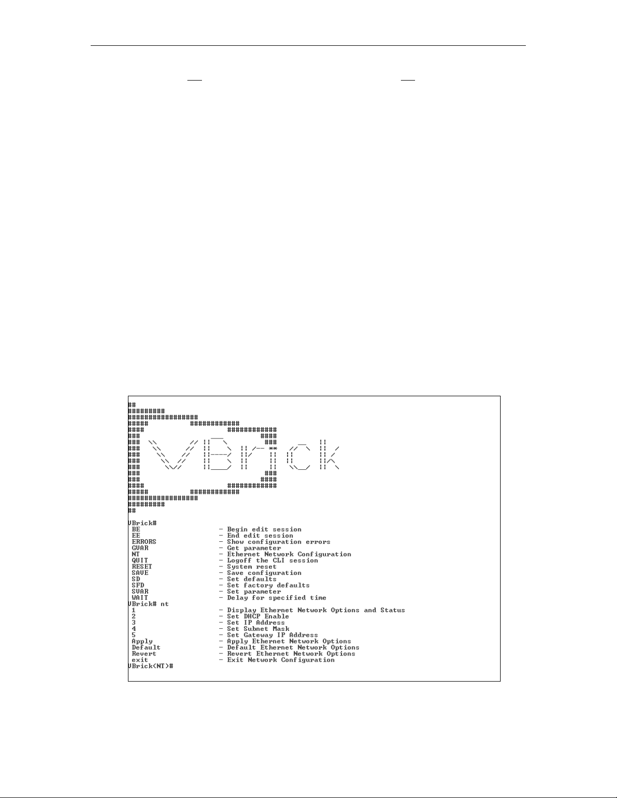
4. When the Command Line Interface is displayed, type "
Network Options. This will let you set IP Address, Subnet Mask, and other options.
5. When done, type "apply" and press
Enter to save your changes.
nt" to display the Ethernet
H.264 Encoding/Decoding Appliance Getting Started Guide 13

5. Verify Streaming Video and Audio
The last step is to verify the appliance is running properly and streaming audio and video.
Assuming you connected a video source as explained in Step 1, you can use the VBAdmin
management application or VBrick StreamPlayer to verify that video is streaming from the
appliance.
Verify Operation with VBAdmin (Windows or Macintosh)
You can verify operation on Windows or Macintosh desktops by playing the stream directly
from the appliance using the VBAdmin management application. This method requires the
Apple QuickTime plugin.
1. Open a browser and launch VBAdmin with the appliance IP Address from Step 3 or Step
4 in the following format:
http://<appliance_ip_address>
Then login with "admin" and "admin"
Note These steps assume that the video source you connected in Step 1 is streaming at
1080i/60. If not streaming at 1080i/60, go to the Encoder Configuration > Video
Input page in VBAdmin and set the "Video Format" to match your actual video
source.
2. Navigate to the Encoder Configuration > Servers page and click the
click on the link labeled "
Click Here to Play Stream."
Edit button. Then
4. This will launch the stream using the QuickTime plugin.
QuickTime 7.0 or higher is required. If QuickTime is not installed, you will be prompted to
download it from Apple.
Note If you have streaming problems with Quicktime 7.0, go to Edit > Preferences >
QuickTime Preferences > Advanced > Video > DirectX and uncheck "Enable
Direct3D video acceleration."
Verify Operation with StreamPlayer (Windows only)
You can verify operation on Windows desktops by playing the stream directly from the
appliance with StreamPlayer 5.3. VBrick's StreamPlayer application lets you receive and play
streaming video originating from the appliance on a PC. You can install StreamPlayer 5.3
from the StreamPlayer Product CD (if purchased) or you can download and install the 30-day
demo version available from our website. Once StreamPlayer is installed:
1. Launch the StreamPlayer application. Go to Start > All Programs > VBrick >
StreamPlayer.
2. In the IP Address field (near bottom of player) type the following text and press Enter:
vbrtsp://<appliance_ip_address>/vbstream1s1
vbstream1s2...1s3...1s4 to test other channels)
(type
3. This will launch the stream in the Windows Media Player. If you hear audio and see
video, you are successfully streaming from the VBrick appliance to your local PC.
14 © 2012 VBrick Systems, Inc.

Appliance Setup
6. Installing Blade Encoders
The VBrick 9000 Series Rack Mount Shelf is a customized enclosure for VBrick blades. It lets
you mix and match 7000 Series blades and 9000 Series blades on the same shelf. It
provides common redundant power sources and common cooling, and supports up to 11
H.264 blade encoders. In general, the blades are fully-functional encoders housed within a
shelf rather than as standalone appliances. Each blade is configured independently of the
others and has its own network connection and IP address. If you purchased blades with your
order they will be packaged separately and not installed in the shelf prior to shipment. Like
the appliance, each blade is configured by default for DHCP. You connect and configure each
blade in the same manner as a standalone appliance. If you have a rack mount shelf, the first
thing you will need to do is install the blades:
1. Find the anti-static wrist strap that was shipped with your order and attach the banana
pin to the receptacle in the upper right corner of the shelf.
2. Unpack and inspect each blade. Remove and save as many blank filler panels as
necessary.
3. Install blades from left to right beginning in Slot 1. Be sure each blade is properly seated
in guides before connecting to the backplane.
4. When properly seated, hand-tighten top and bottom spring-loaded screws.
5. Repeat for each blade and then go to Step 1 on previous page and complete Steps 1–5.
7. Configuring a Decoder
A VBrick 9000 Series decoder is available in a single-channel model or an encoder/decoder
(EnDec) model. Use the following steps to configure and play a decoded stream.
1. Connect a monitor to the
connectors on the breakout cable.
2. On the encoder, launch VBAdmin, go to the Encoder Configuration > Transmitters
page, and enable the transmitter.
3. In the
4. Wait a few moments and the decoded stream will automatically play on the attached
This completes the initial installation and verification. If you can stream and hear video
and audio you are ready to configure your appliance for the real-world streaming video
requirements at your site. The next step is to review the H.264 Appliance Admin Guide. This
document explains all of the possible video and audio configuration options you are likely to
use.
Destination IP Address field enter the unicast IP address of the decoder.
monitor.
A/V connector on the decoder using the component
Front Panel LCD Display
The 9000 Series Enterprise appliance (and blade) has a read-only 2 line x 20 character LCD
screen for informational messages about the appliance and the configuration. When you first
power on the unit, it runs through a power on self-test sequence during which a series of
messages are displayed. During normal operation (when the self tests are complete) the
appliance will cycle through a series of messages as outlined in Table 8 below. As noted, the
display is read-only and cannot be used to set configuration parameters. The first two
messages (see Figure 6) are user-configurable and can be modified on the System
H.264 Encoding/Decoding Appliance Getting Started Guide 15

Configuration > General page in VBAdmin. The backlight color of the LCD display will alert
you to configuration errors or warnings.
VBrick Systems
Release: x.x.x
Figure 6. Front Panel LCD (with Default Data)
The following table shows the sequence of messages displayed on the LCD panel. Note that
on encoder-only appliance models, you will see messages relevant to the encoder. On
decoder-only models you will see those relevant to the decoder. On combination models you
will see messages for the encoder followed by messages for the decoder. The LCD display
scrolls at the rate of one new message every three seconds. The basic sequence of messages is
shown in Table 8.
Note The first two messages in the front panel display are user-configurable and can be
modified (or hidden) on the System Configuration > General page in VBAdmin. See
the H.264 Encoding/Decoding Appliance Admin Guide for details.
Table 8. LCD Message Sequence
Sequence Message Description
1
VBrick Systems
Release x.x.x
IP xxx.xxx.xxx.xxx
Host Name/MAC Address
Basic information (including user description, IP
address, host name/MAC address) is enabled by
default and always present unless disabled in
VBAdmin.
2
Edit Mode
An Edit message is displayed when an Edit session
is in progress.
3
4
5
6
Limited Run Mode
Video Input Problems
Program x (1–4)
Multicast
Unicast
Served
RX x Connected
Program Name
Output Format/Frame Rate
POST Errors
Warning messages are displayed if present.
Encoder messages are displayed if an encoder is
present. They show program information for each
configured transmitters and server.
Decoder messages are displayed if a decoder is
present. They show receiver connected, program
name, and output format/frame rate.
Error messages, if present, are shown last.
Table 9. Front Panel Backlight
State Backlight
Normal Light Blue
Error Red
Warning Yellow
16 © 2012 VBrick Systems, Inc.

Appliance Setup
Front Panel Configuration
You can enable/disable the first two lines of the LCD display (Figure 6) with user-defined
text. You can also enable/disable the display of the host name and IP address. To enter your
own text or enable/disable these options, go to System Configuration > General in
VBAdmin and modify the fields explained below.
Display IP Address Check to display the appliance IPv4 address. Default = enabled.
Display Hostname Check to display the appliance host name. If host name is not
configured (on System Configuration > Network page) the
MAC address is used. Default = enabled.
Display User Description Check to display the first two lines of user-defined text. Default
= enabled.
User Description 1
User Description 2
Enter user-defined text (20 chars. max.) that will be displayed on
first line of LCD panel. Default = VBrick Systems
Enter user-defined text (20 chars. max.) that will be displayed on
second line of LCD panel. Default (\r) = Release x.x.x
H.264 Encoding/Decoding Appliance Getting Started Guide 17

18 © 2012 VBrick Systems, Inc.

Shelf Setup
Topics in this chapter
Shelf Setup Overview . . . . . . . . . . . . . . . . . . . . . . . . . . . . . . . . . . . . . . . . . . . . . . . . . . . . . .19
Installation . . . . . . . . . . . . . . . . . . . . . . . . . . . . . . . . . . . . . . . . . . . . . . . . . . . . . . . . . . . . . . .21
Maintenance . . . . . . . . . . . . . . . . . . . . . . . . . . . . . . . . . . . . . . . . . . . . . . . . . . . . . . . . . . . . . .23
Blade Safety Precautions . . . . . . . . . . . . . . . . . . . . . . . . . . . . . . . . . . . . . . . . . . . . . . . . . . . .25
Shelf Setup Overview
The VBrick 9000 Series Rack Mount Shelf is a customized enclosure for VBrick blades. It lets
you mix and match 7000 Series blades and 9000 Series blades on the same shelf. It provides a
common redundant power source and common cooling and supports 11 VBrick H.264 blade
encoders in a standard 19 in. rack. It has hot-swappable, redundant AC input power supplies
and LED and audible failure alarms. It also has a common, hot swappable cooling unit and a
replaceable air filter. The chassis for a rack mount shelf has a removable cable management
panel (not shown) and card rails that make it easy to insert or remove individual blade
encoders.
Chapter 3
Figure 7. VBrick 9000 Series Rack Mount Shelf
H.264 Blades
In general, the blades are fully-functional encoders housed within shelf rather than as
standalone appliances. Each blade is configured independently of the others and has its own
network connection and IP address. The blades can have Standard Definition connectors (see
H.264 Encoding/Decoding Appliance Getting Started Guide 19

Figure 8) or Standard and High Definition connectors (see Figure 8). In most respects, the
blade models operate in the same manner as the 1RU Industrial models without a front panel
(see
VBrick 9000 Series Appliance Models on page 63) but there are some important
exceptions:
• The blade has a scrolling 8x1 character mini LCD on the face plate.
• The blade displays their shelf slot position (1–11) in the VBAdmin management
program.
• The blade in Slot 1 will read and display shelf manufacturing data from an EEprom on
the backplane.
Figure 8. VBrick H.264 Blade
Table 10. Rack Mount Shelf Specifications
Dimensions • 8U height
• 19 in. EIA rack mount
Fan Tray Unit • Slides out for easy replacement
• Hot swappable
• Visual LED failure indicator
Air Flow • Intake – front bottom
• Output – rear top
Encoder Blades 1–11 VBrick H.264 encoder blades.
Power Supplies • Redundant AC Input
• Hot-swappable
• Visual LED failure indicator and audible alarm
Cable Panel Removable cable management panel allows for easy routing and
management of cables (video, audio, Ethernet, etc.).
20 © 2012 VBrick Systems, Inc.

Shelf Setup
Environmental • Standard operating temperature: 5° to 40° C
• Storage temperature: -45° to 85° C
• FCC Part 15 Class A, CE, UL
• EIA Compliant
• RoHS Compliant
Blade LCD Display
Each blade has an 8x1 character, mini LCD on the faceplate panel that displays eight
characters at a time and scrolls through informational messages. During boot and POST
processing, the LCD will display appropriate messages. Once the encoder is running
normally, the encoder will cycle through the IP address and various other messages for five
seconds each.
Table 11. Mini LCD Color and Messages
Color Message Description
Green
Yellow
Red
Release x.x.x.x
IP:xxx.xx.xxx.x
Warning
Failure
Blade is good.
Blade in warning mode. This can include a DHCP failure, a
video input problem, a temperature problem, or an encoder
in limited run mode.
Blade in failure mode. This can include a POST failure, a
hardware failure, or a hardware mismatch.
Installation
Unpacking and Inspection
Before you do anything else, open the box and inspect the components to make sure you
received everything you ordered. Each shipment comes with the components shown in
Table 12. If anything is missing or damaged, contact VBrick or your reseller at once.
Otherwise install the shelf in a standard 19 in. EIA rack mount chassis.
Note Since the encoder blades are removed from the front, VBrick rack mount units can be
mounted back-to-back (on the same shelf) without consuming additional vertical rack
space. This effectively doubles the density in installations where rack space is an issue.
Table 12. What's in the Box?
9000 Series Blade † Number
H.264 encoder blades 1–11 per shelf
H.264 Quick Start Guide 1 per order
H.264 Product CD 1 per order
Anti-static wrist strap 1 per order
Serial cable and adapter 1 per order
Ethernet cable 1 per blade
H.264 Encoding/Decoding Appliance Getting Started Guide 21

9000 Series Blade † Number
HDMI cable and adapters 1 per channel
A/V breakout cables 1 per slot
The H.264 rack mount shelf must be purchased separately. It includes a cable management panel
†
and 2 AC power supply cords.
Installing the Blades
Note that if you purchased blades with your order they will be packaged separately and not
installed in the rack mount shelf prior to shipment. Each blade is configured by default for
DHCP. You set up and connect each blade in the same manner as a standalone appliance (see
Appliance Setup on page 11). The only difference is that, if necessary, you must use the serial
port to set a static IP address since there is no front panel. (See
on page 13 for details.) Use the provided anti-static wrist strap by attaching the banana pin to
receptacle in upper right corner of the shelf. Ten blank filler panels are included. If you
remove a blade, be sure to install a filler panel to maintain proper air flow. Before installing
blades, be sure to read the
To install individual blades in the shelf:
Blade Safety Precautions on page 25.
1. Unpack and inspect each blade.
2. Remove and save as many blank filler panels as necessary.
3. Install the blades from left to right beginning in Slot 1. (The Slot 1 blade will report
backplane data to VBAdmin if service is ever required.)
4. Each encoder slot has top and bottom card guides. Work carefully and be sure the encoder
card is properly seated in the guides before connecting to the backplane.
5. When done, tighten the spring-loaded screws with a screwdriver to prevent them from
being accidentally removed.
6. Connect audio/video input and network connections.
7. Connect the power cords from the power supplies to AC power and turn on both power
supplies.
4. Find or Set an IP Address
Note Before installing blades, you may want to install ground screws (not included) in the
unpainted area on each side of enclosure. Use #10-32 machine screws to attach earth
ground. When rack-mounting, you can also adjust the mounting ears on each side of
the unit if necessary.
Software Configuration
All blades are independently configurable using the IP address and the VBAdmin
management program. In all respects, blade software configuration is identical to appliance
software configuration. See the H.264 Appliance Admin Guide for details about all
configurable parameters. To identify the blade by slot number, launch VBAdmin, go to the
Monitor > System page, and note the
from left to right. If service is ever required, scroll down to the
only) for manufacturing data associated with the backplane.
22 © 2012 VBrick Systems, Inc.
Slot ID (see below). The blades are numbered 1–11
Add-on Boards table (Slot 1

Shelf Setup
Maintenance
Power Supplies
The Rack Mount Shelf has dual, hot-swappable AC input power supplies (Figure 9). An LED
and an audible alarm will indicate if either of the power supplies has failed. If a power supply
fails, contact VBrick for a replacement as soon as possible. Do not attempt to repair a power
supply as this will invalidate the warranty. Although the shelf will operate with a failed power
supply, a redundant power supply will ensure there is no downtime. Each supply can handle a
full load of 500W if the other supply has failed or been turned off. There will be no loss of
service time if only one supply fails. If both are active, they will load share (50/50) to support
the rack.
Table 13. AC Input Voltage and Frequency (iStarUSA Model IS-500R8P)
Parameter Minimum Nominal Maximum Max. Current
Voltage (115V) 90 VAC 100–120 VAC 132 VAC 8A
Voltage (230V) 180 VAC 200–24 VAC 264 VAC 4A
Frequency 47 Hz 50/60 Hz 63 Hz
Table 14. Power Supply LEDs
Color Description
Green Power supply is good.
Yellow AC power is applied but power supply is off.
H.264 Encoding/Decoding Appliance Getting Started Guide 23

Color Description
Red The power supply has failed.
If a power supply fails, the LED will turn red and an alarm will sound. Push the alarm reset
button (the small black bubble button to the left of the left power cord receptacle) to silence
the alarm.
To remove/replace the power supply:
1. Turn off power to the power supply with switch at bottom and unplug power cord.
2. Pull unit out with handle while pressing the red release lever.
3. When replacing a power supply, push in firmly to seat firmly in backplane.
Figure 9. Dual Power Supplies
Fan Tray
The shelf has a common fan tray with four fans and a replaceable air filter. There are no
user-serviceable components in the fan tray. If an individual fan fails, you must replace the
entire unit or you will invalidate the shelf warranty. Contact VBrick for a replacement fan tray
as soon as possible. The
damaging the blades, do not run the shelf if more than one fan has failed. When you pull out the fan
tray, you can see the fans slowly spinning down. Any fan
Table 15. Fan Tray LEDs
Color Description
Green Fan tray is good.
Red The fan tray has failed and should be replaced as soon as possible. Do not run
the shelf if more than one fan has failed or the tray been removed.
To remove/replace the fan tray:
1. Loosen the screws on each side of unit.
2. Press the
REQ (Request) button. This will power down the fan tray. The status LED will
go from green to red and the
3. Remove the tray and determine how many fans have failed (see above). Do not run the
shelf if more than one fan has failed.
4. Contact VBrick for a replacement fan tray as soon as possible.
5. When powering down the fan tray to install a replacement, work quickly to avoid
overheating the blades.
Status LED will turn red if any of the fans has failed. To avoid
not spinning down has likely failed.
OK LED will illuminate blue.
24 © 2012 VBrick Systems, Inc.

Figure 10. Fan Tray Controls and Indicators
Air Filter
The air intake unit at the bottom of the enclosure has a replaceable filter element. Inspect
and replace the filter element every 90 days—more often in challenging environments. For
best results, use replacement filters from VBrick. You need not power off the shelf to replace
the filter element.
To remove/replace the filter element:
1. Loosen the screws on each side and remove the entire unit.
2. Replace the filter with a VBrick-supplied replacement element.
Blade Safety Precautions
Shelf Setup
Use common sense when installing the blade server. Do not expose the unit to direct
sunlight, high humidity or wet conditions. Do not block the air vents or impede the airflow in
any way.
important safety precautions.
Before you rack mount the blade server, please take a moment to read the following
Restricted Location.
exposed when the fan tray or the blades are removed, this equipment must be installed
in a restricted location with limited access for authorized users who are familiar with
the electrical hazards and required safety precautions. It should not be used in a home,
school, or other area accessible to the public. To be installed only in restricted access
areas (dedicated equipment rooms, equipment closets, or the like) in accordance with
Articles 110-26, 110-27 or the National Electric Code ANSI/NFPA70, or per the
applicable code in the country of installation.
Operating Temperature.
ambient temperature may be greater than the room ambient. Install the equipment in an
environment compatible with the maximum ambient temperature (Tma) specified by
the manufacturer.
Reduced Air Flow. Do not restrict air flow in any way. Rack mount the equipment so
that the amount of air flow required for safe operation is not compromised.
Mechanical Loading. Avoid uneven mechanical loading. When rack-mounting the
equipment, be sure that the devices are evenly balanced.
Circuit Overloading. Do not overload the supply circuits. Be aware of the effect that
overloading the circuits can have on overcurrent protection and supply wiring. Refer to
the equipment nameplate ratings for details.
Reliable Earthing. The rack-mounted equipment must be reliably earthed. This
particularly applies to power strips and other indirect connections to the branch circuit
Because of hazardous energy circuits on the backplane that are
If installed in a closed or multi-unit rack, the operating
.
H.264 Encoding/Decoding Appliance Getting Started Guide 25

Replaceable Battery. Do not attempt to replace the battery since it may explode if
replaced incorrectly. Return to VBrick Support Services for replacement with the same
or equivalent type of battery. VBrick will dispose of used batteries in accordance with
manufacturer recommendations.
26 © 2012 VBrick Systems, Inc.

Software Upgrade
Topics in this chapter
Software Upgrade. . . . . . . . . . . . . . . . . . . . . . . . . . . . . . . . . . . . . . . . . . . . . . . . . . . . . . . . . . 27
Software Upgrade
Note When you purchased your network video appliance from VBrick, it was shipped with
the latest software already installed and no additional software installation is necessary.
If you ever need to reinstall the software, you can get it from the
our website. Use the following instructions only when upgrading the software.
VBrick appliances are shipped with PC applications that allow for easy upgrade. Once the
release is installed, the upgrade tools become available in the VBrick program group, located
under Start > All Programs > VBrick. The upgrade procedure can be invoked by using either
the VBDownload application or the VBDirectory application. Either application can be used
as the starting point for updating the appliance's flash memory (TCP/IP FTP transport
services are used for this). Using VBDirectory is an easier method since it lets you choose the
appliances by name instead of IP address. When VBrick appliances are not accessible to
VBDirectory, the VBDownload application must be used. Also keep in mind the following
considerations:
Chapter 4
Downloads page on
• All saved configuration parameters are saved when you upgrade your encoder and there
is no need to reconfigure the unit after an upgrade. The upgrade process requires a unit
reset, so be sure to save your configuration prior to the upgrade.
• Part of the install process occurs during the first reboot after the upgrade. Do not power
off the unit during this time. The process may take 5 minutes and include an automatic
reboot of the unit. The appliance is ready for operation when you are able to login via
VBAdmin or CLI.
• VBrick strongly recommends against loading a earlier version of code. As a general rule,
never downgrade a unit to a code version older than what was originally installed at the
factory. If you do load an earlier version of code, reset all parameters to the factory
defaults and remove the external USB drive (if present) before the downgrade.
Installing a Software Upgrade
To upgrade a VBrick:
1. Double-click on the release executable (
your PC. It is recommended that you accept the default destination folder which is
Program Files\VBrick\VB9000\download\ReleaseVx_x_x.
2. The setup programs for VBDownload and VBDirectory will automatically run after the
files have been extracted. Click
if possible.
Next, follow the instructions, and use the default folders
SetupVB9000_x_x_x.exe) to install the release on
H.264 Encoding/Decoding Appliance Getting Started Guide 27

3. When the Maintenance Complete page is displayed, click Finish.
4. Go to
Start > All Programs > VBrick > VBDirectory to start the management utility. The
VBDirectory program will show all VBrick appliances available for upgrade.
5. Select the device to be updated by highlighting the name and then click the
Upgrade
button. (If the user name and password are not set, a dialog box will appear and you will
need to configure the appliances's username and password (default =
admin/admin).
6. In the VBDownload window, if you installed the release to the default directory, that
directory will be auto-selected in the
Revision Folder. If not, Browse to the directory
that contains the unzipped files from the release package.
7. Select a
VBDownload is
which release components need to be downloaded. When prompted, press
Revision and click OK to start the download. Since the default mode of
Intelligent Download the utility will query the VBrick to determine
OK to allow
VBDownload to upgrade the suggested components. This may take several minutes.
8. When the download completes, reboot the appliance using the
Reset Unit radio button
and follow the prompts.
9. Note that part of the upgrade takes place during the first boot after the download and
may take up to 5 minutes. The upgrade is complete when you can login via VBAdmin or
CLI, or when its name is refreshed in VBDirectory.
10. When done close the window or click
Note To verify the download has successfully installed, check the
Revision
field on the VBAdmin "Welcome" page.
Exit.
Application Code
Configuring VBDownload
The VBDownload application is used to upgrade VBrick appliances. When you click on the
setup executable, the application files are automatically installed in
Files\VBrick\VB9000. If you have both VB6000 Series devices and VBrick 7000-8000-9000
devices present, the application will default to the
28 © 2012 VBrick Systems, Inc.
VBrick 7000-8000-9000 folder.
Program

Software Upgrade
Experienced VBrick users can modify this default behavior by creating a new shortcut for
VBDownload that uses
To configure the VB6000 folder as the default folder:
VB6000 as the default folder.
1. Go to Start > All Programs > VBrick.
2. Highlight
new shortcut and select
3. Enter a meaningful name, highlight it, then right-click and select
4. In the
VBDownload then right-click and select Create Shortcut. Then highlight the
Rename.
Properties.
Target field, append the following text, beginning with a space, to the existing
path. (Note that question marks are required for any spaces in the path.)
-i "" -f C:\Program?Files\VBrick\VB6000\Download\ReleaseVx_x_x
5. Replace ReleaseVx_x_x with the actual version number of the setup file and click OK
when done.
H.264 Encoding/Decoding Appliance Getting Started Guide 29

30 © 2012 VBrick Systems, Inc.

Management Tools
Overview
The VBAdmin configuration tool is an intuitive GUI-based management tool and VBrick
recommends using VBAdmin as the primary means of managing VBrick appliances. You can
also use any of the following tools to manage a VBrick:
Table 16. VBrick Management Tools
Management Tool Description
VBAdmin The VBAdmin management interface allows quick and secure
control through the VBrick's IP interface. See
on page 35.
VBDirectory The H.264 Appliance Product CD includes VBDirectory, an
application that facilitates finding, accessing, and upgrading all
VBricks on a network. For more information, see the
VBDirectory online help.
Chapter 5
Using VBAdmin
Command Line Interface The Command Line Interface provides management through
the VBrick's COM port. See
HyperTerminal on page 43 or Connecting with Telnet or SSH
on page 43.
SNMP SNMP commands through VBrick's IP interface, including
SNMP Traps.
Web Services You can set any configuration parameter in the MIB using an
industry-standard Web Service.
Auto Configuration See System Configuration > Manage Configuration in the
H.264 Appliance Admin Guide.
Note There is only one active editing session allowed at any time in a single appliance. In
VBAdmin it is possible to exit a session which still in
must determine whether or not to log off the previous editor. For best results, click
Finish Edit before you exit the VBAdmin page. Note that Telnet, CLI and SNMP
automatically log you out when you exit the program.
Connecting via the COM Port with
Edit mode. Other users then
VBAdmin
The appliance has an embedded web server lets you manage the configuration from an
external browser. This allows network managers to remotely configure and monitor the
appliances from virtually anywhere in the world. VBAdmin is compatible with Internet
Explorer and Firefox (other browsers may not give acceptable results). For best results,
VBrick Systems recommends Internet Explorer 8.0 or Firefox 9.0 (or higher). You connect to
VBAdmin by pointing to the IP Address (e.g.
and logging in. VBAdmin is one of several ways to manage a VBrick appliance. There are
http://172.17.5.5) of the VBrick appliance
H.264 Encoding/Decoding Appliance Getting Started Guide 31

other methods but VBAdmin's graphical user interface is the easiest to use. VBAdmin is
described in detail in
Figure 11. VBAdmin Home Page
VBAdmin on page 35.
VBDirectory
VBrick provides a management application called VBDirectory that provides quick reference
and access to all VBrick Appliances on a network. VBDirectory v4.4 or higher is compatible
with H.264 appliances. VBDirectory is automatically installed with a software upgrade and is
also available on the H.264 Appliance Product CD. For more information, see the
VBDirectory User Guide which is also included on the H.264 Appliance Product CD.
Figure 12. VBDirectory
32 © 2012 VBrick Systems, Inc.

Management Tools
Command Line Interface
VBrick network appliances can be configured using a standard ASCII terminal or terminal
emulator program connected to the serial port (
MIB-based CLI can be used to access all VBrick parameters. (Keep in mind that all
parameters that are available in the MIB-based CLI are also available in the web-based
VBAdmin application. Always use VBAdmin unless you have a compelling reason to use the
command line.) You can use HyperTerminal or other interfaces to run the CLI. For more
information see
Command Line Interface on page 43.
COM 1) on the rear of the appliance. The
VBrick appliances can also be managed remotely via industry-standard Telnet. The same
suites of menus that are displayed on a local terminal are instantly available over an IP
network. VBrick uses the standard Telnet port (23). Telnet uses the same commands as
Command Line Interface (CLI). The Telnet and HyperTerminal applications are both
referred to as CLI or Command Line Interface. For more information see
Command Line Interface on page 43.
SNMP
The VBrick appliance can also be configured and managed through its MIB which is available
on the Product CD or on the VBrick website. Various SNMP (Simple Network Management
Protocol) management tools are available to issue SNMP based commands to the appliance.
The command structure is similar to CLI and Telnet. It is necessary to become the active
editor and apply the changes before they take effect in the appliance. Note that the SNMP
community strings are the usernames. The following screen shows a typical, freeware MIB
browser.
H.264 Encoding/Decoding Appliance Getting Started Guide 33

Web Services
For customers who want to build custom applications, the VBrick 9000 Series SDK provides
a standards-based SOAP architecture to programmatically interface to the appliance. It
includes detailed documentation that explains how to configure and control appliances via
command line scripts. The SDK is sold separately and is not bundled with other VBrick
products. Contact a VBrick sales
the SDK.
representative or your certified VBrick reseller to purchase
Auto Configuration
Auto Configuration lets you perform a configuration via a URL script file. It is typically used
for remote configuration and troubleshooting or to configure VBrick appliances that are
behind a firewall. To configure a parameter on an appliance (or more likely a set of
parameters) you simply point the URL to a server with an .xml configuration file. This is
useful, for example, to change a transmitter destination address, set the audio and video rates,
etc. when the VBrick appliances are behind a firewall and cannot be accessed remotely. See
System Configuration > Manage Configuration in the H.264 Appliance Admin Guide for
complete details.
34 © 2012 VBrick Systems, Inc.

VBAdmin
Topics in this chapter
Using VBAdmin. . . . . . . . . . . . . . . . . . . . . . . . . . . . . . . . . . . . . . . . . . . . . . . . . . . . . . . . . . .35
Using VBAdmin
The VBrick H.264 Appliance has an integrated management interface (VBAdmin) that lets
you manage VBrick configuration from an external browser. This allows network managers
to remotely configure and monitor the appliances from virtually anywhere. As shown in
Table 17 you can launch VBAdmin in Internet Explorer or Firefox (other browsers are not
supported by VBrick). You connect to VBAdmin by pointing to the IP Address (for example:
http://192.168.5.5) of the VBrick appliance and logging in. (Note that passwords passed
between client and server are encrypted.) VBAdmin is one of several ways you can manage
the VBrick encoder (for example you can also use Telnet or the
but VBAdmin is the easiest to use.
Table 17. Supported Browsers
Chapter 6
Command Line Interface)
Browser Version
Microsoft Internet Explorer 8.0 or higher
Mozilla Firefox 9.0 or higher
To login to a VBrick 9000 Series appliance with Microsoft Internet Explorer, you must have
Session Cookies and Active Scripting enabled. Depending on your browser version, these
settings are in the
correct username and password will refresh the screen without login. If
cannot be enabled, check with your system administrator to see if it was disabled at the server
level. To avoid having the VBAdmin window automatically close when accessing a different
VBrick appliance, go to Tools > Internet Options > Advanced and uncheck the
windows for launching shortcuts.
Security or Privacy tabs in Internet Options. If either option is disabled, a
Active Scripting
Reuse
H.264 Encoding/Decoding Appliance Getting Started Guide 35

Login Page
Figure 13. Login Page
To login to VBAdmin:
1. Enter the IP address of the H.264 appliance in the address bar.
2. When the login page is displayed, login to VBAdmin with a valid user name and
password (case-sensitive), and then click the
password is
admin and admin. It is highly recommended that you use the Maintenance
pages in VBAdmin to change the user name and password. The user name and password
cannot exceed 20 characters. It may include any combination of alphanumeric characters
and only the following special characters:
Log In button. The default user name and
~ ! # $ ^ * + & [ ] { } | < >
Table 18. Default Passwords and Privileges
User Level Default User Name Default Password Privileges
Administrator admin admin Read, diagnostics, edit, change
passwords.
Operator operator operator Read, diagnostics, edit.
Diagnostics diagnostics diagnostics Read, diagnostics.
Public public public Read.
Home Page
The first time you launch VBAdmin you will need to page down and accept the End User
License Agreement before you can login. A successful login will then display the "Welcome
to VBAdmin" page shown below. This is the "home" page; it provides system information
and the colored LEDs in the middle of the page give you a quick snapshot of the health and
status of the appliance.
36 © 2012 VBrick Systems, Inc.

Figure 14. Welcome Page
Configuration Menu
VBAdmin
The options on the Configuration Menu (see Figure 14) are shown below. This menu
provides access to all configurable features and functions on the appliance. It also provides
access to the help system. All configuration options are described in detail in the H.264
Appliance Admin Guide. Use the (plus and minus) tree controls in the Configuration Menu to
expand or collapse the selectable options and note that many pages have additional links to
hide or show less frequently used settings.
Home Provides a quick snapshot of appliance health and status
Dashboard Shows a high-level overview of the entire unit. This includes the
configured values for each slot and channel, the streams
associated with each program, and the transmitters and servers
associated with each stream.
System Configuration Used to configure "system" settings such as IP address and host
name as well as user names and passwords. Also let's you read,
reset, or restore the system configuration. Advanced
Configurations are used for security, logging, event triggering
and other less frequently used options.
Encoder Configuration Used to set video and audio parameters for the encoder.
Decoder Configuration Used to set video and audio parameters for the decoder.
Monitor Lets you view system, network, and audio/video data as well as
the various system logs. Program Status lets you view the status
of programs, transmitters, and servers.
Troubleshoot Lets you troubleshoots operational problems by running network
tests and devices tests.
Logout Logs you out of the system.
Help Launches the online help system.
H.264 Encoding/Decoding Appliance Getting Started Guide 37

LED Indicators
The colored LEDs in the middle of the page give you a quick snapshot of the health and
status of the appliance. These indicators are dynamically refreshed every five seconds and
give you an up-to-the-minute snapshot of the current status. On a decoder appliance, you will
only see
Encoder LEDS
Decoder LEDs
Video Input and Alarms.
Video Input Checks whether
Video State on the Monitor > Encoder Status > Video
Input page is running or not running.
• Green – Running.
• Red – Video Input problem.
Streaming Checks whether the
State on the Monitor > Encoder Status >
Transmitters page is transmitting or not transmitting. This includes any
configured transmitters or any server clients connected to the appliance.
• Green – at least one transmitter or server client is streaming.
• Yellow – no transmitters or server clients are streaming.
Alarms Checks whether the
System Traps on the Monitor > System Logs page
has any bad traps (for example a temperature alarm or a POST failure)
that were not cleared.
• Green – no alarms are present.
• Red – one or more alarms are present.
Configuration Checks for configuration errors or invalid input on any appliance
configuration pages.
• Green – no configuration errors are present.
• Yellow – one or more configuration errors are present.
Edit Mode
In order to change configuration settings in the VBrick encoder, you must click Edit to
become the active editor so that multiple users cannot be changing parameters at the same
time. After clicking
Progress is displayed on the front panel of the appliance. Only one user can be in Edit mode at
Edit, the button changes to Finish Edit, and the message Edit Session In
any time. Any user can end the current editing session of any other user regardless of login
level—admin or operator. As a best practice, you should click
changes and then click
Note All configuration screens have a
document are shown in
38 © 2012 VBrick Systems, Inc.
Save and Finish Edit to avoid interfering with other users.
View mode and an Edit mode. All screens in this
Edit mode, that is after you have clicked the Edit button.
Edit, make any necessary

VBAdmin
Figure 15. Begin Edit
Be aware that some parameters, menu items, and fields are not shown unless you are in edit mode.
Click the
Edit button to see all fields, parameters, and buttons. VBAdmin validates most user
entries. If you select and apply invalid settings or mismatched parameters, it will display error
messages in red showing the valid range of values or a description of the conflicting
parameters. When this happens, try again with different values or parameters and press
Apply.
Figure 16. Finish Edit
H.264 Encoding/Decoding Appliance Getting Started Guide 39

If the browser is closed after entering Edit mode, editing will not be ended. Therefore, a
second user can't know if the first user has simply forgotten to log off or is still engaged in
editing. After an hour of inactivity, Edit mode times out, whether the browser is open on the
desktop or closed without ending the Edit session. In VBAdmin, the
Logout button on the
left side of the menu bar ends editing and logs you out of the application.
Using Apply, Revert, and Default
Depending on screen resolution, it may be necessary to scroll down the page to see additional
information and fields. The
the bottom of the page when appropriate. You may also see
and other buttons depending on what page you are on.
Apply Applies the changes made on the screen to the appliance. Note that these
changes will not be stored in the appliance's flash memory until you click
Save. This means if the appliance is powered down the changes will be lost.
Don't forget to save the configuration.
Revert Aborts all changes made on the screen and returns to the values that were
present prior to the first change that was made. Note that this only applies to
changes made prior to the last "apply."
Default Returns to the default settings for all parameters on the page. You must still
click
Apply for the settings to take effect.
Apply, Revert and Default buttons however, are always shown at
Clone, Refresh, Reset Counters,
Clone When configuring the Video Input on
multi–channel encoders, this button lets
you apply one set of configuration
parameters to one or more of the other
channels.
Finish Edit Ends the editing session and displays View mode.
Save Writes all applied changes to Flash
memory. If you do not click Save after
editing, any changes you made are lost if
the appliance loses power or is reset.
Resetting the Appliance
To reset the VBrick appliance do one of the following:
1. Power the VBrick appliance off and on by removing and reinserting the power cord.
2. Press the
available in
Reset button on the System Configuration > General page. This button is only
Edit mode.
Note Some changes to the configuration will initiate an automatic reboot. When this
happens, wait approximately 60 seconds, then refresh the page and log back in with
your user name and password.
40 © 2012 VBrick Systems, Inc.

VBAdmin
Logout
Click Logout on the Configuration Menu to exit VBAdmin and automatically end any editing
sessions. After logging out of VBAdmin, it is a good idea to close the window and exit
Internet Explorer.
Help
A link to the online help system is available from the Configuration Menu on the left side of
the VBAdmin page. This help system has a powerful full-text search engine that can quickly
find the information you need. You may wish to take a few minutes to familiarize yourself
with the help system. It can save time when tying to find information about appliance
parameters or options. When using VBAdmin, click on the question mark hyperlink in the
upper-right corner of each page to get context-sensitive help for that page.
Note The online help system requires an Internet connection but can be configured to run
on your local web server. See "Configuring Local Online Help" in the H.264 Appliance
Admin Guide for more information.
H.264 Encoding/Decoding Appliance Getting Started Guide 41

Figure 17. Online Help Page
42 © 2012 VBrick Systems, Inc.

Command Line Interface
Although VBAdmin is the preferred management interface you can also access the appliance
configuration using the Command Line Interface. Some users prefer to use the Command
Line.
Topics in this chapter
Connection Modes. . . . . . . . . . . . . . . . . . . . . . . . . . . . . . . . . . . . . . . . . . . . . . . . . . . . . . . . .43
Command Line Interface . . . . . . . . . . . . . . . . . . . . . . . . . . . . . . . . . . . . . . . . . . . . . . . . . . . . 44
Connection Modes
This section explains how to access VBrick appliance parameters using the COM serial port
or over an IP network. You can use HyperTerminal or ProComm with the serial port for
example, or Telnet or PuTTY over an IP network. To send input commands to a VBrick
appliance, you can use ProComm, Telnet, scripts, cut-and-paste, or any program that supplies
text-based input via the get and set commands.
Chapter 7
Connecting via the COM Port with HyperTerminal
To manage an appliance via terminal emulation (for example with HyperTerminal), connect
the included cable (which provides a standard 9-pin serial connection) from the serial port on
your computer to the VBrick's
HyperTerminal go to
Connect through your computer's COM Port (usually COM1) with the following settings.
Bits per second 9600
Data bits 8
Parity None
Stop bits 1
Flow control None
When you connect to a terminal, a prompt for login (username) and password will be
displayed. Login and password are case sensitive (
appear by typing a question mark (
Start > Programs > Accessories > Communication > HyperTerminal.
COM RJ-45 connector. To access the VBrick using
admin). Once logged in, the main menu will
?) at the vbrick> prompt.
Connecting with Telnet or SSH
VBrick appliances can be managed remotely via industry-standard Telnet or an SSH client
like
PuTTy. With Telnet the same commands that are displayed on a local terminal are
instantly available over an IP network. VBrick uses the standard Telnet port. See
Command
H.264 Encoding/Decoding Appliance Getting Started Guide 43

Line Interface on page 44 for an explanation of the commands that are available.
Note Telnet (as well as FTP, VBAdmin, SNMP, and front panel data) can be disabled on the
VBrick appliance for security purposes. If you cannot login to the appliance via Telnet,
check that the
External Telnet Server is enabled. Open VBAdmin and go to System
Configuration > Advanced Configurations > Security.
To login using Telnet:
1. Go to
2. Type
Start > Run and type telnet to open a Telnet window.
open <ip_address> using the IP address of the VBrick Appliance. This will launch
Command Line Interface.
3. Enter the Login name and Password. Default is
4. At the VBrick prompt, type
? to display the top-level commands.
Command Line Interface
The Command Line Interface is a VBrick program used to manage configuration parameters
for the appliance. It provides a subset of commands that you can use if you cannot access
VBAdmin. Regardless of whether you access the CLI through HyperTerminal (shipped with
Windows) or Telnet, the command structure is the same. The CLI interface is launched as
soon as you enter a valid Login name and Password. The following window shows the
Command Line Interface and the "shortcut" commands that are available using the
command. You can use these shortcuts at any time during an editing session.
admin and admin.
?
Using the MIB
All VBrick appliance parameters are accessible via an industry-standard SNMP Management
Information Base (MIB). The CLI is a syntactically simple interface which is suitable for
scripting. The syntax for each VBrick parameter is documented in the SNMP MIB for the
appliance.
44 © 2012 VBrick Systems, Inc.

Command Line Interface
Use these basic steps to find and set VBrick appliance parameters with the CLI:
1. Find the parameter you want to set or change. See
Finding VBrick Parameters on
page 45.
2. Set the parameter using valid values obtained from the MIB. See
Setting VBrick
Parameters on page 48.
3. Apply the changed value(s) using the
the MIB. See
Applying Changes on page 49.
4. Optional. Save the configuration file. See
ApplySet command for that group as specified in
Saving Changes on page 50.
The Get and Set commands are shown in the following table. All CLI commands are shown
in Table 21 on page 48. You will need to login to the VBrick and begin an edit session before
you can make any changes. Once the parameters have been set to the correct values, you must
ApplySet. If the response to any ApplySet does not match the value of the set, an error
do an
message is displayed. Use care when typing commands. All commands and parameter
names are case sensitive. All parameter names must be prefixed by "vbrick".
Table 19. Get and Set Command Syntax
Command Response
GVAR vbrickMIBNAME
SVAR vbrickMIBNAME=value
$!MIBNAME=value
$!MIBNAME=value
or $!ERROR=errorstring
or $!ERROR=errorstring
Note The serial port is also used by the VBrick appliance to emit system messages. In order
to allow the script writer to distinguish between direct responses to commands and
other output, all CLI response messages have
$! as leading characters. Any responses
that do not begin with these characters can be safely ignored.
It is important to note that some commands also cause a reboot of the VBrick. In order to
notify the command initiator when this happens, the string
$!Rebooting … is emitted from
the VBrick. In this case the commanding entity must be prepared to wait before continuing
the editing session. In practice, it is unlikely that any automated program will be tasked with
initiating any tasks that will cause a spontaneous reboot.
Finding VBrick Parameters
The best way to find a parameter name is by viewing the Configuration Log. Once you find
the parameter name, you can check the MIB using a MIB browser to verify the definition and
usage.
To locate a parameter name using the Configuration Log:
1. Use VBAdmin to set or change a parameter and click
2. Then go to Monitor > System Logs > Configuration Log
see a configuration log message reporting the exact name of the parameter you just
changed.
3. Verify the definition and usage of the parameter by examining the MIB file with either a
standard MIB browser or a text editor.
4. You can use this parameter name in a script. Make sure you prefix the parameter name
vbrick, for example: vbrickProgramTransmitterName
with
Apply.
and examine the log. You will
H.264 Encoding/Decoding Appliance Getting Started Guide 45

The following example shows how the Transmitter Name in VBAdmin is associated with
vbrickProgramTransmitterName in the MIB. First find the Transmitter Name parameter name
using the Configuration Log. Then open the appropriate MIB file (see Table 20 below) in a
MIB browser. The valid value for this variable is
DisplayString. If the syntax calls for an
integer, use a numeric value; if the syntax calls for a string, use an alpha value.
To find the VBrick parameter name and syntax:
1. Find and change the parameter in VBAdmin.
2. Go go to the Monitor > System Logs > Configuration Log and find the name of the
parameter you just changed.
3. Open the appropriate MIB file in a MIB browser and view the syntax. Once you know
the syntax, you can use the correct variable name and value on the Command Line.
46 © 2012 VBrick Systems, Inc.

Command Line Interface
Working with MIB Files
The MIB files provide read-only access to all configurable encoder parameters and are
organized as shown in Table 20. To access any MIB variable, open the appropriate file in a
MIB browser. The easiest way to visualize VBrick's control structure is to understand the
relationship between the VBAdmin and the MIB. To get started, open a MIB file in a text
editor or a MIB browser. For the most part, parameters are grouped according to where they
appear on the VBAdmin pages. Once you find the parameter, other related parameters are
usually contained in the same group. Each of the top-level groups comprises a page in
VBAdmin. Note that valid values for the selected parameter are shown next to the
column in the lower left area of the window in the MIB browser example above.
Table 20. MIB Files
MIB Description
vbrick_reg.mib
vbrickEncoder.mib
This file is used as a reference by the MIB browser.
Contains encoder parameters including video, audio, configuration,
and status parameters.
vbrickProgram.mib
vbrickSystem.mib
Contains transmitter, server, and SAP parameters.
Contains IP address, network traps, auto-config, front panel
configuration, etc.
vbrickDecoder.mib
Contains decoder parameters including receiver IP address, jitter
queue settings, etc.
Syntax
H.264 Encoding/Decoding Appliance Getting Started Guide 47

Setting VBrick Parameters
Logging In
The first step is to connect to the VBrick appliance using whatever method is appropriate at
your site (e.g. Telnet, HyperTerminal, etc.). When logging in, you are prompted for a login
name and password. These credentials give you access to the VBrick and are typically
provided by an administrator. When the
logged in. The CLI shortcut commands are shown below.
Login: <username>
Password: <password>
VBrick#
Table 21. CLI Shortcut Commands
Command Description
BE
DEBUG
EE
ERRORS
GVAR
NT
QUIT
RESET
SAVE
SD
SFD
SVAR
WAIT
Begin edit session
Generate a debug file if requested by VBrick Support Services.
End edit session
Show configuration errors
Get parameter
Ethernet Network Configuration
Logoff the CLI session
System reset
Save configuration
Set defaults
Set factory defaults
Set parameter
Delay for specified time
vbrick> prompt is displayed, you are successfully
Beginning or Ending an Edit Session
To begin a CLI edit session, first login as explained above, and then enter the first two
commands shown below using the same username you used to login to the VBrick. You only need
to do this at the start of an edit session or if someone has ended your edit session. Also, you
only need to begin an edit session to set variable and table parameters—not to get parameters.
You can get parameters without starting an edit session. When your edit session is done, and
after you have applied or saved your changes, do an end edit. You can also use the Begin Edit
(
BE) and End Edit (EE) shortcut commands shown in Table 21.
To begin an edit session:
VBrick# SVAR vbrickEditName=
VBrick# SVAR vbrickEditName=<admin>
To end an edit session:
VBrick# SVAR vbrickEditName=
48 © 2012 VBrick Systems, Inc.

Command Line Interface
Getting or Setting Variables
Use the following format to get or set a variable. This command shows how to read the unit's
MAC address but is only an example. Use the actual parameter name and value as shown in
the MIB.
Finding VBrick Parameters on page 45 explains how to do this. All parameter
names must be prefixed by "vbrick".
VBrick# gvar vbrickManufacturingInfoMacAddress
Valid system commands display a response in the following format:
$!vbrickManufacturingInfoMacAddress=00:07:df:01:07:8e
Invalid system commands display an error response in the following format:
$!ERROR=SNMP GET failure
Note Double quotes (" ") may be used for any strings but they must be used if the string
contains spaces. For example, you can use the following syntax to create a blank space
in the
ManagementSAPGroupName:
svar "vbrickManagementSapGroupName=Madrid VBrick"
Getting or Setting Table Variables
Table variables can be single-indexed where there is only one instance of a variable (for
example an IP address) or double-indexed where there are multiple instances (for example
TransmitterName). As shown below, when viewing the Configuration Log, single-indexed
table variables will be appended with "
with "
.n.m"
.n". Double-indexed table variables will be appended
Single Index Example
This example shows how to read and change the
VBrick# gvar vbrickEncoderVideoCommonBrightness.1
$!vbrickEncoderVideoCommonBrightness.1=50
VBrick# svar vbrickEncoderVideoCommonBrightness.1=75
$!vbrickEncoderVideoCommonBrightness=75
Brightness parameter on Channel 1.
Double Index Example
This example shows how to read and change the Rate 1
VBrick# gvar vbrickEncoderVideoH264Resolution.1.1
$!vbrickEncoderVideoH264Resolution.1.1=15
VBrick# svar vbrickEncoderVideoH264Resolution.1.1=2
$!vbrickEncoderVideoH264Resolution=2
Resolution parameter on Channel 1.
Applying Changes
The ApplySet command is used to apply changes. There is one ApplySet command per
program group in the MIB and the syntax varies slightly according to the group. Use this
command, for example
you made with an
the trailing
=2.
vbrickProgramTransmitterApplySet, to actually apply the change(s)
SVAR or a STAB. An ApplySet is always written in the following format with
H.264 Encoding/Decoding Appliance Getting Started Guide 49

VBrick# svar vbrickEncoderVideoCommonApplySet.1=2
It is important to note that some ApplySets can cause the VBrick appliance to send
unsolicited messages. For example, the appliance may reboot with the following message:
$!Rebooting …
Saving Changes
Once you are done, you must save to persistent storage if you want your edits saved in the
configuration file. Unless you save the configuration, any changes you have made will be lost
if the appliance reboots. A save is always written in the following format with the trailing
=2.
Note that some changes to the configuration will reboot the VBrick in which case you must
wait for it to reset. Note that you can also use the
VBrick> svar vbrickSysSaveConfiguration=2
SAVE command as a shortcut.
Error Handling
Programming errors, for example syntax errors, illegal values, etc. display informational
messages in the CLI, for example
issues, for example a dropped connection or a failed save (see below) are shown in the System
Log (open VBAdmin and go to Monitor > System Logs > Configuration Log
You can also see all configuration errors using the
potential errors in advance by getting the value of various status parameters in the VBrick.
For example, if you are writing a script, you might want to check
Status before you set parameters for a related task.
$!ERROR=Value out of range. Other system or network
to see the log).
ERRORS command. You can also detect
Transmitter State or FTP
Resetting the Appliance
Use the following command (or the RESET shortcut) to reset the appliance. A reset is simply a
reboot. It does not change or reset any configured parameters.
vbrick> svar vbrickSysReset=2
CLI Examples
The following examples show two common configuration tasks. Remember that you only
need to begin an edit session at the start of an edit session or if someone has ended your edit
session. You only need to end an edit session when you are done, and after you have applied
or saved your changes. Also remember that an
comments are not allowed on the same line as a command.
Example 1
This example shows how to read and set the
Channel 2. User input commands are shown in bold text.
VBrick# gvar vbrickEncoderVideoH264TargetBitRate.2.1
$!vbrickEncoderVideoH264TargetBitRate.2.1=750000
Then it sets and applies the Target Bit Rate to 800K.
VBrick# svar vbrickEncoderVideoH264TargetBitRate.2.1=800000
ApplySet command is always required and
Target Bit Rate for the first video rate on
$!vbrickEncoderVideoH264TargetBitRate=800000
VBrick# svar vbrickEncoderVideoCommonApplySet.1=2
$!vbrickEncoderVideoCommonApplySet=2
50 © 2012 VBrick Systems, Inc.

Example 2
Command Line Interface
This example shows how to set the unicast
Destination IP Address and enable the transmitter
for Program1 and Transmitter1.
VBrick# svar vbrickProgramTransmitterInetAddrType.1=1
VBrick# svar vbrickProgramTransmitterInetAddr.1=172.22.118.105
VBrick# svar vbrickProgramTransmitterEnable.1=2
VBrick# svar vbrickProgramTransmitterApplySet.1=2
Scripting Syntax
• Script commands must start in column 1.
svar (set variable) must precede the variable name.
•
• Wait time is defined milliseconds. A value of 1000 = 1 second.
• Most variable changes require an
• There is no clear command.
• There is no chaining of scripts.
• Comments are not allowed on the same line as a command.
• Comments start with
// in column 1.
• Blank lines are not allowed.
• All scripts are executed in a strictly serial manner by a single task.
• While executing a script it is possible to miss a double change of any event.
ApplySet.
H.264 Encoding/Decoding Appliance Getting Started Guide 51

52 © 2012 VBrick Systems, Inc.

Chapter 8
Web Services
Topics in this chapter
Web Services Interface. . . . . . . . . . . . . . . . . . . . . . . . . . . . . . . . . . . . . . . . . . . . . . . . . . . . . .53
Web Services Interface
VBrick 9000 Series appliances provide a standards-based SOAP architecture to programmatically
interface to the appliance. The Web Service interface allows the user application to
parameters in the appliance. The methods supported by the service are listed below.
Table 22. Web Services Methods
Method Description
getNewSessionId (device)
Used to get a new session id from the appliance. It allows the
web service to maintain session with the appliance.
test (echoString)
Used as a test web service method to test if the interface to
the appliance is working. It returns the input string as an
echo.
login (sessionId, loginName,
hashedPassword)
beginEdit (sessionId, editName)
Used as method to allows the user to login into the box as a
particular user with appropriate privileges. Returns
successful,
ERROR otherwise.
Used as a method to begin the edit session to become editor
of parameters. Returns
editName if successful, ERROR
otherwise.
endEdit (sessionId)
endOtherEdit (sessionId)
logout (sessionId)
getParameterValue (sessionId,
parnName, parmIndex)
setParameterValue (sessionId,
parmName, parmIndex, parmValue)
setMultipleParameterValue
(sessionId, parmName, parmValue,
count)
Used as a method to end the editor session. Returns OK if
successful,
ERROR otherwise.
Used as a method to forcefully end another editor session.
Returns
OK if successful, ERROR otherwise.
Used to logout of a web session. Returns OK if successful,
ERROR otherwise.
Used as a parameter to get a parameter value. Returns
parameter value as a string if successful,
Used as a method to set a parameter value. Returns OK if
successful,
ERROR otherwise.
Used as a method to set multiple parameter values, where
parmName is a string array of names, parmValue is a string array
of values to the corresponding array of names, and count is
the number of items in the array. Returns
ERROR otherwise.
Get/Set MIB
OK if
ERROR otherwise
OK if successful,
H.264 Encoding/Decoding Appliance Getting Started Guide 53

The WSDL file for the web service methods can be obtained by calling the following URL
where
<appliance_ip_address> is the IP address of the appliance or a host name that can be
resolved to an IP by the local DNS server.
http://<appliance_ip_address>/VBrickWebSrvc/VBrickWebSrvc.wsdl
All methods return ERROR as the response if the request cannot be fulfilled. OK is returned for
methods that complete successfully.
test returns the input string as an echo. In order to set parameters, the user must be
authenticated and must also be an active editor (by calling
GetNewSessionId returns a new SessionId if it succeeds;
beginEdit). A typical sequence of
calls to the methods is shown below.
Note There are multiple ways to locate and verify VBrick parameters. See Setting VBrick
Parameters on page 48 for more information.
To Get a parameter value:
1. Get a new SessionId by calling
2. Login into the appliance by calling the
getNewSessionId.
login method and supplying the login name and
hashed password value. The algorithm to hash the password is provided as "C" code and
also as a VBCrypt package for the Microsoft .NET and C# environments.
3. Get the parameter value by calling the
getParameterValue method supplying the MIB
name and parameter Index (if any). Note: Some parameters may require the user to be
the active editor. More parameters can be retrieved by calling the method several times.
4. Logout of the session by calling the
logout method.
To Set a parameter value:
1. Get a new SessionId by calling
2. Login into the appliance by calling the
getNewSessionId.
login method and supplying the login name and
hashed password value. The algorithm to hash the password is provided as "C" code and
also as a VBCrypt package for the Microsoft .NET and C# environments.
3. Call the
4. Set the parameter value by calling the
beginEdit method to become the active editor in the box.
setParameterValue method supplying the MIB
name, parameter Index (if any), and parameter value. More parameters can be set by
calling the method several times, or by calling the
5. End the edit by calling
6. Logout of the session by calling the
endEdit
logout method.
setMultipleParameterValue method.
Note If you successfully login to the appliance, you must logout when your session
completes or subsequent users will be unable to access the appliance. You should end
edit and logout if login or begin edit were successful regardless of the success or
failure of your Get or Set call.
54 © 2012 VBrick Systems, Inc.

Streaming Video Basics
Topics in this chapter
Video Basics. . . . . . . . . . . . . . . . . . . . . . . . . . . . . . . . . . . . . . . . . . . . . . . . . . . . . . . . . . . . . .55
Getting the Best Video . . . . . . . . . . . . . . . . . . . . . . . . . . . . . . . . . . . . . . . . . . . . . . . . . . . . .55
Network Considerations . . . . . . . . . . . . . . . . . . . . . . . . . . . . . . . . . . . . . . . . . . . . . . . . . . . . 56
VBrick Accessories. . . . . . . . . . . . . . . . . . . . . . . . . . . . . . . . . . . . . . . . . . . . . . . . . . . . . . . . . 56
Serial Port Passthrough . . . . . . . . . . . . . . . . . . . . . . . . . . . . . . . . . . . . . . . . . . . . . . . . . . . . .56
Video Basics
It is important that the source of the video being encoded and streamed is of the highest
possible quality in order to avoid using unnecessary bandwidth to transport source video
artifacts, distortion, etc. If using a camera, exercise common sense: good lighting and a steady
camera will improve overall performance. Cameras, DVD players, and live television
broadcast feeds from a TV tuner can all be used as video sources. VBrick supports standard
video via BNC connectors, or HDMI via mini-DIN connectors. BNC-to-RCA adapters are
readily available if RCA-type cables are used.
Chapter 9
Getting the Best Video
Video quality is a subjective concept that depends on a variety of factors. VBrick's
philosophy is to make our network appliances as flexible as possible so they can be used
effectively in different applications on a wide variety of networks. This means you can
configure an appliance for maximum performance but you can also configure it in such a way
that it will only work well in a very limited environment. Video quality is also relative. What is
acceptable quality for a surveillance application on a low-bandwidth network is most likely
unacceptable for a corporate presentation or a two-way video conference on a high-speed
LAN. Much depends on your network, the bandwidth you have available, and the audience
you are trying to reach.
For best results, start with the default values and then adjust the bit rate, frame rate,
resolution, and other parameters with care. Experiment with different settings to see the
trade-offs in quality and performance. You can track your changes by periodically saving the
configuration file using the
VBAdmin. If the audio and video quality is still less than you would expect, re-apply your
saved configuration and try again. Keep in mind that the VBrick is stable, reliable and
flexible. In most cases a small amount of experimentation will help you find the
configuration settings that will deliver the best audio and video your network can support.
For more information, or help configuring your appliance, contact VBrick
Read and Restore options on the Manage Configuration page in
Support Services.
H.264 Encoding/Decoding Appliance Getting Started Guide 55

Network Considerations
Assigning Multicast Addresses
Many factors must be considered when designing a multicast address infrastructure since
Ethernet switch implementations can significantly vary between vendors. Furthermore,
multicast addressing techniques rely on an Ethernet to IP Address mapping rule, which does
not guarantee a unique physical address. In fact, it is possible to create multicast addresses
that differ from an IP perspective, but overlap when presented to the Ethernet network.
Addresses created in this situation can cause significant network and operational problems.
Specifically, multiple IP Addresses are mapped into the same physical layer address. For
example, all IP multicast addresses with the same or differing first octet, and the second octet
differing by exactly 128, map to the same physical address (226.5.5.4, 227.5.5.4, and
228.133.5.4 all map to the same physical address). Another factor to keep in mind when
assigning multicast addresses is that 224.x.x.x is a range containing reserved addresses,
particularly in the range 224.0.0.x. For example, 224.0.0.1 is the 'all hosts' multicast address
and 224.0.0.2 is the 'all routers' reserved address. Other 224.0.0.X numbers are reserved for
RIP, OSPF, DVMRP, etc. Here are some recommended rules for multicast IP Address
assignment:
1. Do not use 224 in the first octet since many of these are reserved.
2. Use a digit between (225–239) for the first octet and standardize on it for each network.
3. In the second octet, either use numbers from 1–127,
given network.
or 129–255, do not mix ranges on a
VBrick Accessories
VBrick appliances have various optional hardware accessories. These work directly with
VBrick appliances or through the use of ActiveX control software, also available from
VBrick. For information about microphones, cameras and other VBrick hardware
accessories, please contact VBrick directly. ActiveX controls for cameras and other software
accessories are also available from VBrick.
Serial Port Passthrough
When configured properly, VBricks provide full duplex, end-to-end transparent passthrough
of user data from one VBrick to another, or to other IP devices. You can use COM1 or
COM2 for passthrough. When COM1 Passthrough is enabled, the management port and CLI
are not available. The serial ports operate at the configured baud rate (e.g. 110 to 115.2K
bps). See the H.264 Admin Guide for passthrough configuration details. Some common
applications include:
• Remote control of a camera, pan-tilt-zoom.
• Remote control of a security door lock.
• Low speed data transport.
• Data collaboration between PCs.
Note Passthrough mode is used to send control information from one VBrick to another
and may not support sustained data at higher data rates.
56 © 2012 VBrick Systems, Inc.

Streaming Video Basics
How Passthrough Works
VBrick appliances are able to receive data on a particular TCP/IP port and transparently
output that data to a serial port. Conversely, any data input to a serial port can be passed
through to other devices connected to that TCP/IP port. Devices include other VBricks or
special applications connected to the appropriate TCP/IP port. This feature is called "Serial
Port Passthrough." COM is assigned port 4439. A typical application is for two VBricks
connected to each other's TCP/IP port 4439. In this case, characters typed into a terminal
program attached to one VBrick's serial port appear on a terminal program attached to the
other VBrick's serial port. In this case, the TCP/IP network serves as an intermediary
between the serial ports of two VBrick appliances.
You must select configuration settings to enable Serial Port Passthrough. First it is necessary
to decide if the appliance will be designated as an
connections. If configured as an
Initiator it will continuously attempt to setup a Passthrough
connection to other devices. When configured as a
connections from
Initiator appliances. It is possible to Disable Passthrough Mode, so that the
VBrick neither initiates nor responds to Passthrough requests. If a VBrick is set to be an
Initiator, a Destination must be selected. The appliance will use the destination information
when trying to establish a connection. The destination can be configured as follows:
Initiator or Responder of Passthrough
Responder it will accept up to 64
Dedicated Means that the initiator will attempt to make a Passthrough connection
to the configured Dedicated Destination and Port. The Dedicated
Destination can either be configured using IP Address or Host Name.
If set to Host Name, the Resolved Destination IP Address is derived
from the Host Name parameter. If set to IP Address, the Resolved
Destination IP Address is derived from the IP Address parameter.
Since the medium used for setting up Passthrough connections is a generic TCP/IP port, any
IP device that is prepared to connect to a VBrick's port can be considered as a Passthrough
Initiator. The VBrick Responder appliance will not know the exact nature of the device at the
other end of the port. For example, a generic Telnet client configured to connect to a VBrick
on port 4439 will cause a VBrick
the connection it accepted from the Telnet client. If the appliance is configured as an
and the
Responder appliance has Passthrough disabled or is not on the network it will
Responder to start sending data from it's serial port, using
Initiator
continue to try to establish a connection.A VBrick appliance must be configured as a
Responder to accept Passthrough connections initiated by other devices. In addition to the
Initiator versus Responder selection, the serial port operation settings must be entered to
establish a connection, baud rate, stop bits etc.
Note Once a Passthrough connection is established between VBricks, the actual flow of data
is symmetric between the ends of the connection. That is, the behavior of the serial
ports with respect to typed characters will appear to be the same at both ends.
H.264 Encoding/Decoding Appliance Getting Started Guide 57

Serial Port Passthrough Using Telnet
As mentioned in the previous section, either serial port can be accessed over Ethernet via a
Telnet client. A VBrick appliance configured as a Passthrough Responder will accept a
connection request to TCP port 4439 (COM). The request can come from a Telnet client or
other PC application. Any data sent by the PC to TCP port 4439 will be delivered out of the
VBrick serial ports and any data present on the VBrick serial port will be sent to the
connected PC.
If multiple Telnet sessions are active on one VBrick (each VBrick supports up to 64 sessions),
the data from the VBrick will be sent to all connected PC's, and the data received by the
VBrick from the PC's will be delivered on the serial port. If multiple Telnet sessions are
active and each is sending data to the VBrick, the data delivered by the RS-232 port will be a
mix of characters presented in the order they were received (e.g. the data from all the senders
is bridged together). This feature provides a method to broadcast alarm status or other
information to multiple locations.
58 © 2012 VBrick Systems, Inc.

VBrick iPhone App
Topics in this chapter
Overview . . . . . . . . . . . . . . . . . . . . . . . . . . . . . . . . . . . . . . . . . . . . . . . . . . . . . . . . . . . . . . . .59
Monitoring an Appliance . . . . . . . . . . . . . . . . . . . . . . . . . . . . . . . . . . . . . . . . . . . . . . . . . . . .60
Running Scripts . . . . . . . . . . . . . . . . . . . . . . . . . . . . . . . . . . . . . . . . . . . . . . . . . . . . . . . . . . . 60
Overview
Note The VBrick iPhone app is used to monitor the status of 7000/9000 Series encoders
only. It does not provide support for VBrick 9000 Series decoders.
VBrick provides an iPhone app which you can use to monitor the status of 7000/9000 Series
H.264 devices. This app lets you perform basic configuration tasks by running predefined
scripts. You cannot modify configuration parameters except by running a script. You can create and
FTP script files that perform common tasks like changing the bit rate or starting a
transmitter. These scripts are associated with the four function keys (F1–F4) on the iPhone
interface. F1 runs script 1, F2 runs script 2, etc. You cannot change the script file names (e.g.
event1Script.txt) nor can you add more scripts. After you create the scripts, you will need
to FTP them to the
Command Line Interface on page 44. This topic explains how to find and set appliance
parameters. These are the actual MIB object names you will need to identify in your scripts.
scripts folder on the appliance. If you need help creating scripts, see the
Chapter 10
Figure 18. iPhone App Home Page
Getting the App
The VBrick iPhone app is available from the Apple App Store. To get the app simply click on
the App Store icon on your iPhone home page and search for "VBrick" apps. There is no
charge for the VBrick iPhone app.
H.264 Encoding/Decoding Appliance Getting Started Guide 59

Monitoring an Appliance
Be aware that to use the iPhone app, your iPhone must be on the same wireless network as
the 7000/9000 Series encoder appliance.
To launch the VBrick iPhone app:
1. Tap on the VBrick icon to launch the app. The page will show any 7000/9000 Series
devices that have manually added or discovered.
2. Click on the icon to manually add devices. You will be prompted for Name, IP
Address, and login credentials. When done select a Default Device (if desired).
3. Tap on any available device to see the home page for the device.
4. Click on the Monitor button to display a list of Channels and then select any available
Channel. This will display (below right) the relevant status values for the selected
Channel. These values are read-only and cannot be changed.
Running Scripts
The iPhone app supports four predefined scripts that you can use to modify appliance
configuration parameters. (This is the only way you can modify parameters using the iPhone
app.) After you create and FTP these scripts (to the
use them to modify configuration parameters on the appliance. You run the script by tapping
the
Control icon. F1 is associated with script1, F2 with script 2, etc. You can also change the
scripts folder on the appliance), you can
60 © 2012 VBrick Systems, Inc.

VBrick iPhone App
label names (below the buttons) as desired (see below Changing the Function Key Labels). If
the script runs successfully you will see a confirmation message.
Creating Script Files
Script files are simply .txt files with a list of one or more commands. For a detailed
description of how to create scripts that will change appliance parameters, see
on page 50. As noted, you can create and FTP script files that will perform common
configuration tasks. For example the following script sets the
Target Bit Rate for the first
video rate on Channel 2 to 800K.
CLI Examples
VBrick# svar vbrickEncoderVideoH264TargetBitRate.2.1=800000
VBrick# svar vbrickEncoderVideoCommonApplySet.1=2
Script files have explicit, predefined names that cannot be changed. There are also specific
syntax rules that must be observed (see
that every configuration element in the script is followed by an appropriate
Scripting Syntax on page 51). In particular make sure
applyset
command. The script file names include:
event1Script.txt
event2Script.txt
event3Script.txt
event4Script.txt
Note When you are ready to start writing your own scripts, the
scripts folder on the 9000
Series Product CD has sample scripts that will help you get started.
FTPing Script Files
After creating a script, it must be FTPed to the appliance before you can use it. You can use
an FTP program or you can use the FTP functionality in VBAdmin:
To FTP scripts using VBAdmin:
1. Open VBAdmin and go to System Configuration > Advanced Configurations > Event
Triggering.
2. Click on
3. When the FTP directory page is displayed, click
Windows Explorer.
Edit and again on FTP Scripts.
Page, and then click Open FTP Site in
H.264 Encoding/Decoding Appliance Getting Started Guide 61

4. When the Windows Explorer page is displayed, drag the new script file(s) into the
window.
Changing the Function Key Labels
You can use CLI (or a script) to modify Function key labels (F1–F4). Each of the following
commands is associated with a specific function key. Replace the bolded text below with a
meaningful label that describes the script. Do not exceed 20 characters including spaces.
svar "vbrickFrontPanelUserFunctionDescription.1=F1 label"
svar "vbrickFrontPanelUserFunctionDescription.2=F2 label"
svar "vbrickFrontPanelUserFunctionDescription.3=F3 label"
svar "vbrickFrontPanelUserFunctionDescription.4=F4 label"
svar vbrickFrontPanelApplySet=2
62 © 2012 VBrick Systems, Inc.

Chapter 11
VBrick 9000 Series Reference
Topics in this chapter
VBrick 9000 Series Appliance Models . . . . . . . . . . . . . . . . . . . . . . . . . . . . . . . . . . . . . . . . . . 63
Device Interfaces . . . . . . . . . . . . . . . . . . . . . . . . . . . . . . . . . . . . . . . . . . . . . . . . . . . . . . . . . . 64
External Event Triggering . . . . . . . . . . . . . . . . . . . . . . . . . . . . . . . . . . . . . . . . . . . . . . . . . . . 66
VBrick 9000 Series Appliance Models
VBrick network appliances come in a variety of models and configurations. The following
tables will help to identify your model and explain it characteristics.
Table 23. Form Factors
9000 Series Appliance Part Number
Blade † 9304-0000-00
Industrial 9302-0000-000
Enterprise 9301-0000-111
† Requires Rack Mount Chassis (P/N 8570-1000)
Table 24. Audio/Video Modules (AVMs) †
Audio/Video Module Part Number Channels Max Streaming Resolution
XPS 9000 Encoding AVM ††
SD 1CH HDMI/YPbPr
XPS 9000 Encoding AVM
SD 2CH HDMI/YPbPr
HPS 9000 Encoding AVM †††
HD 1CH HDMI/YPbPr
HPS 9000 Encoding AVM
HD 2CH HDMI/YPbPr
XPS 9000 Encoding AVM
SD 1CH HDMI/YPbPr/
SD-HD-3G-SDI/Composite
HPS 9000 Encoding AVM
HD 1CH HDMI/YPbPr/
SD-HD-3G-SDI/Composite
9300-4214-000 1 SD 720x480/720x576
9300-4312-000 2 SD 720x480/720x576
9310-4214-000 1 1080p60
9310-4312-000 2 1080p60
9300-4211-000 1 SD 720x480/720x576
9310-4211-000 1 1080p60
HPS 9000 Decoding AVM
HD 1CH HDMI/YPbPr/
SD-HD-3G-SDI/Composite
H.264 Encoding/Decoding Appliance Getting Started Guide 63
9310-5211-000 1 1080p60

† Each Blade or Appliance can be populated with one or two AVMs.
†† XPS = Extended Performance System: encodes at standard resolutions only.
††† HPS = High Performance System: encodes at standard and high definition resolutions.
Device Interfaces
Video-In
Table 25. Support Video Inputs
Interface Description
Component The component connectors (YPbPr) on the A/V cable support high
definition video and audio.
Composite The yellow jack with an RCA connector is used for composite video
input.
HDMI The
SDI The Serial Digital Interface supports both SD-SDI typically used for
HDMI (High-Definition Multimedia Interface) connector supports
both digital audio and video.
broadcast-grade video (meets SMPTE 259M) or HD/3G-SDI which
processes 1080p at bit rates of 2.97 Gbits/sec (meets SMPTE 424M).
Audio-In
Each channel on the encoder can accept digital audio via the HDMI port (Digital L+R 1/2) or
analog audio using the A/V breakout cable (
Multimedia Interface) carries high-quality multichannel audio. It moves the audio across the
TMDS lanes using a packet structure. The audio can be sampled at rates of 32, 44.1, or 48
KHz.
Table 26. Supported Digital Audio Formats
Format Description
HDMI HDMI 1.1 compatible audio interface (basic audio).
Unbalanced). The HDMI port (High Definition
COM 1/COM 2
RS-232/422/485 COM Port Pinouts
The encoder has two COM ports. COM 1 is generally used for management (9600 8N1)
although it can also be used for passthrough; COM 2 is used for passthrough. When COM1
Passthrough is enabled, the management port and CLI are not available. The COM
Passthrough Port is used to pass control information between VBrick appliances over the
network. The
port operates at a default rate of 9.6 Kbps, Async, 8-Bit, No Parity, Controls = None. The
pins on the passthrough port can be set for RS-232 or RS-422-485 (see below) using the
Interface Type parameter on the Passthrough page in VBAdmin.
COM port presents a standard DTE interface on an RJ-45 connector. The serial
COM
Note See Configuration: Passthrough in the VBrick H.264 Appliance Admin Guide for
detailed information about Passthrough configuration.
64 © 2012 VBrick Systems, Inc.

Table 27. RS-232 Pinouts
VBrick 9000 Series Reference
Pin Function Direction
1 RTS Request to Send Output
2 DTR Data Terminal Ready Output
3 TXD Send Data Output
4 Ground Common
5 Ground Common
6 RXD Receive Data Input
7 DSR Data Set Ready Input
8 CTS Clear to Send Input
Table 28. RS-232-422/485 Pinouts
Pin Description
1 TD(+)
2 N/C
3 TD(-)
4 Optional gnd/common or n/c (GND
connected to cable shielded)
5 Optional gnd/common or n/c (GND
connected to cable shielded)
6 RD(-)
7 N/C
8 RD(+)
H.264 Encoding/Decoding Appliance Getting Started Guide 65

Ethernet
The Ethernet port is used to connect the appliance to your network. It uses a standard 10/
100/1000 cable.
Power
The power entry interface supplies 24VDC to the appliance from an external 110/220 VAC
power source.
External Event Triggering
The 9000 Series event triggering feature lets you use an external switch to control the
function of the VBrick. This section provides some examples of how to use this feature. In
all the examples, a high event is triggered when the switch is closed and a low event is
triggered when the switch is opened. The event trigger inputs on the VBrick recognize a high
voltage anywhere above +8 volts DC with an upper limit of +12 volts. A low voltage is
anything at or below 0 volts DC with a lower limit of -12 volts. The event can also be
configured to run a script on Pin 7. See "Advanced Configurations > Event Triggering" in
the Admin Guide for configuration details; see
pinout details.
Note You cannot execute a script using an event trigger if VBAdmin is currently running in
Edit mode. If you run a script directly from VBAdmin, it automatically exits Edit mode
and terminates the active editing session.
RS-232/422/485 COM Port Pinouts for
The 9000 Series encoder has two COM ports and supports a total of four external events.
Note that Pin8 is used for UART control and cannot be used as a trigger.
Table 29. Input Event and Associated Scripts
Input Event Runs This Script
COM1 pin7 High to Low event1Script.txt
COM1 pin7 Low to High
COM2 pin7 High to Low
COM2 pin7 Low to High
A total of four trigger voltage outputs are available for generating trigger inputs. The outputs
can be forced high or low (the voltage depends on whether you select RS232 or RS422/485)
and are configured on the Passthrough page. (Note that passthrough is only supported on
COM 2 so COM 1 outputs cannot be forced). The outputs are:
COM1 pin1 RTS
COM1 pin2 DTR
COM2 pin1 RTS
COM2 pin2 DTR
event2Script.txt
event3Script.txt
event4Script.txt
66 © 2012 VBrick Systems, Inc.

VBrick 9000 Series Reference
Example 1
This example uses an external power source. Connect an external power supply (+8V to
+12V) and a switch directly to the ground pin and an event pin of the COM 2 port on the
appliance.
Example 2
This example uses the VBrick COM port output. Connect the COM output pin (COM2 pin1
RTS or COM2 pin2 DTR) through a switch to a COM event pin. For this method to work,
you must force the desired output pin (RTS or DTR) to
To force the desired output pin to On:
On using VBAdmin:
1. Go to the System Configuration > Advanced Configurations > Passthrough page in
VBAdmin.
2. Change
3. Change
4. Change
5. Click
Passthrough State to Responder and click Apply.
RTS/DTR Control to Force On and click Apply.
Passthrough State to Disabled and click Apply.
Save Config when done.
H.264 Encoding/Decoding Appliance Getting Started Guide 67

68 © 2012 VBrick Systems, Inc.


VBrick Systems, Inc.
12 Beaumont Road
Wallingford, CT 06492, USA
 Loading...