

Page 1
VBrick Multi-Format Set Top Box
Multi-Format Set Top Box v2.2.5
Quick Start Guide
January 2016
Page 2

Copyright
© 2016 VBrick Systems, Inc. All rights reserved.
2121 Cooperative Way, Suite 100
Herndon, VA 20171, USA
This publication contains confidential, proprietary, and trade secret information. No part of this document may be copied,
photocopied, reproduced, translated, or reduced to any machine-readable or electronic format without prior written
permission from VBrick Systems, Inc. Information in this document is subject to change without notice and VBrick assumes
no responsibility or liability for any errors or inaccuracies. VBrick, VBrick Systems, the VBrick logo, VEMS Mystro,
StreamPlayer, and StreamPlayer Plus are trademarks or registered trademarks of VBrick Systems, Inc. in the United States
and other countries. Windows Media, SharePoint, OCS and Lync are trademarked names of Microsoft Corporation in the
United States and other countries. All other products or services mentioned in this document are identified by the
trademarks, service marks, or product names as designated by the companies who market those products. Inquiries should be
made directly to those companies. This document may also have links to third-party web pages that are beyond the control of
VBrick. The presence of such links does not imply that VBrick endorses or recommends the content of any third-party web
pages. VBrick acknowledges the use of third-party open source software and licenses in some VBrick products. This freely
available source code is posted at
http://www.vbrick.com/opensource
About VBrick Systems
Founded in 1998, VBrick Systems is a privately held company that has enjoyed rapid growth by helping our customers
successfully introduce mission critical video applications across their enterprise networks. Since our founding, VBrick has
been setting the standard for quality, performance and innovation in the delivery of live and stored video over IP networks—
LANs, WANs and the Internet. With thousands of video appliances installed world-wide, VBrick is the recognized leader in
reliable, high-performance, easy-to-use networked video solutions.
VBrick is an active participant in the development of industry standards and continues to play an influential role in the
Internet Streaming Media Alliance (ISMA), the MPEG Industry Forum, and Internet2. In 1998 VBrick invented and shipped
the world's first MPEG Video Network Appliance designed to provide affordable DVD-quality video across the network.
Since then, VBrick's video solutions have grown to include Video on Demand, Management, Security and Access Control,
Scheduling, and Rich Media Integration. VBrick solutions are successfully supporting a broad variety of applications
including distance learning and training, conferencing and remote office communications, security, process monitoring,
traffic monitoring, business and news feeds to the desktop, webcasting, corporate communications, collaboration, command
and control, and telemedicine. VBrick serves customers in education, government, healthcare, and financial services markets
among others. VBrick products are manufactured in an ISO certified manufacturing facility.
Page 3

Multi-Format STB v2.2.5 Quick Start
Preface . . . . . . . . . . . . . . . . . . . . . . . . . . . . . . . . . . . . . . . . . . . . . . . . . . . . . . . . . . . . . . . . . . .v
Organization . . . . . . . . . . . . . . . . . . . . . . . . . . . . . . . . . . . . . . . . . . . . . . . . . . . . . . . . . . . . . .v
Copyright . . . . . . . . . . . . . . . . . . . . . . . . . . . . . . . . . . . . . . . . . . . . . . . . . . . . . . . . . . . . . . . . .v
Getting Help . . . . . . . . . . . . . . . . . . . . . . . . . . . . . . . . . . . . . . . . . . . . . . . . . . . . . . . . . . . . . vi
Font Conventions . . . . . . . . . . . . . . . . . . . . . . . . . . . . . . . . . . . . . . . . . . . . . . . . . . . . . . . . . vi
Environmental Considerations . . . . . . . . . . . . . . . . . . . . . . . . . . . . . . . . . . . . . . . . . . . . . . . vi
1. Getting Started
Overview . . . . . . . . . . . . . . . . . . . . . . . . . . . . . . . . . . . . . . . . . . . . . . . . . . . . . . . . . . . . . . . . .1
Creating STB Users . . . . . . . . . . . . . . . . . . . . . . . . . . . . . . . . . . . . . . . . . . . . . . . . . . . . . . 1
Hardware Specifications . . . . . . . . . . . . . . . . . . . . . . . . . . . . . . . . . . . . . . . . . . . . . . . . . . 2
Installation . . . . . . . . . . . . . . . . . . . . . . . . . . . . . . . . . . . . . . . . . . . . . . . . . . . . . . . . . . . . . . . .2
Start Mode . . . . . . . . . . . . . . . . . . . . . . . . . . . . . . . . . . . . . . . . . . . . . . . . . . . . . . . . . . . . . . . . 4
Local Mode . . . . . . . . . . . . . . . . . . . . . . . . . . . . . . . . . . . . . . . . . . . . . . . . . . . . . . . . . . . . 4
Local Fullscreen Mode . . . . . . . . . . . . . . . . . . . . . . . . . . . . . . . . . . . . . . . . . . . . . . . . . . . 4
Portal Server Mode (VEMS 5.x) . . . . . . . . . . . . . . . . . . . . . . . . . . . . . . . . . . . . . . . . . . . . 5
Portal Server Mode (VEMS 6.x) . . . . . . . . . . . . . . . . . . . . . . . . . . . . . . . . . . . . . . . . . . . . 6
Contents
2. Configuration
Displaying the Setup Page . . . . . . . . . . . . . . . . . . . . . . . . . . . . . . . . . . . . . . . . . . . . . . . . . . . .9
Changing the IP Address. . . . . . . . . . . . . . . . . . . . . . . . . . . . . . . . . . . . . . . . . . . . . . . . . . 9
STB Configuration . . . . . . . . . . . . . . . . . . . . . . . . . . . . . . . . . . . . . . . . . . . . . . . . . . . . . . . . . 10
Adjusting the Display Area of Output Devices (VEMS 5.x) . . . . . . . . . . . . . . . . . . . . .14
Adjusting the Display Area of Output Devices (VEMS 6.x) . . . . . . . . . . . . . . . . . . . . .15
Upgrade, Reset, Change Password. . . . . . . . . . . . . . . . . . . . . . . . . . . . . . . . . . . . . . . . . . . . . 16
3. Creating a Channel Guide
Overview . . . . . . . . . . . . . . . . . . . . . . . . . . . . . . . . . . . . . . . . . . . . . . . . . . . . . . . . . . . . . . . . 17
Configuring channels.xml. . . . . . . . . . . . . . . . . . . . . . . . . . . . . . . . . . . . . . . . . . . . . . . . . . . .17
Sample Channels File . . . . . . . . . . . . . . . . . . . . . . . . . . . . . . . . . . . . . . . . . . . . . . . . . . . 18
Sample URLs. . . . . . . . . . . . . . . . . . . . . . . . . . . . . . . . . . . . . . . . . . . . . . . . . . . . . . . . . . 21
Updating channels.xml. . . . . . . . . . . . . . . . . . . . . . . . . . . . . . . . . . . . . . . . . . . . . . . . . . . . . .22
Using wget. . . . . . . . . . . . . . . . . . . . . . . . . . . . . . . . . . . . . . . . . . . . . . . . . . . . . . . . . . . .22
Using vi . . . . . . . . . . . . . . . . . . . . . . . . . . . . . . . . . . . . . . . . . . . . . . . . . . . . . . . . . . . . . .22
Hosting channels.xml on a PC. . . . . . . . . . . . . . . . . . . . . . . . . . . . . . . . . . . . . . . . . . . . . . . . 23
Configuring a PC as a Web Server . . . . . . . . . . . . . . . . . . . . . . . . . . . . . . . . . . . . . . . . .23
Putting the Files on a PC . . . . . . . . . . . . . . . . . . . . . . . . . . . . . . . . . . . . . . . . . . . . . . . .24
Configuring the STB Home Page . . . . . . . . . . . . . . . . . . . . . . . . . . . . . . . . . . . . . . . . . . 24
Using Multiple channel.xml Files. . . . . . . . . . . . . . . . . . . . . . . . . . . . . . . . . . . . . . . . . . . . . . 25
Configuring Multiple Channel Files . . . . . . . . . . . . . . . . . . . . . . . . . . . . . . . . . . . . . . . . 25
Testing the Configuration . . . . . . . . . . . . . . . . . . . . . . . . . . . . . . . . . . . . . . . . . . . . . . . . 27
Multi-Format STB Quick Start iii
Page 4

4. Managing the Set Top Box
Overview . . . . . . . . . . . . . . . . . . . . . . . . . . . . . . . . . . . . . . . . . . . . . . . . . . . . . . . . . . . . . . . . 29
Telnet. . . . . . . . . . . . . . . . . . . . . . . . . . . . . . . . . . . . . . . . . . . . . . . . . . . . . . . . . . . . . . . .29
VBDirectory . . . . . . . . . . . . . . . . . . . . . . . . . . . . . . . . . . . . . . . . . . . . . . . . . . . . . . . . . . 30
Setup . . . . . . . . . . . . . . . . . . . . . . . . . . . . . . . . . . . . . . . . . . . . . . . . . . . . . . . . . . . . . . . . 30
Web Interface . . . . . . . . . . . . . . . . . . . . . . . . . . . . . . . . . . . . . . . . . . . . . . . . . . . . . . . . .31
5. Software Upgrade
Overview . . . . . . . . . . . . . . . . . . . . . . . . . . . . . . . . . . . . . . . . . . . . . . . . . . . . . . . . . . . . . . . . 33
Using the Setup Program . . . . . . . . . . . . . . . . . . . . . . . . . . . . . . . . . . . . . . . . . . . . . . . . . . . . 33
Using Telnet. . . . . . . . . . . . . . . . . . . . . . . . . . . . . . . . . . . . . . . . . . . . . . . . . . . . . . . . . . . . . . 34
Telnet Examples . . . . . . . . . . . . . . . . . . . . . . . . . . . . . . . . . . . . . . . . . . . . . . . . . . . . . . . 34
Using an IIS Server . . . . . . . . . . . . . . . . . . . . . . . . . . . . . . . . . . . . . . . . . . . . . . . . . . . . . . . . 35
Mass Upgrade Using a VEMS Server . . . . . . . . . . . . . . . . . . . . . . . . . . . . . . . . . . . . . . . . . . 36
1. Unlock the Upgrade Image . . . . . . . . . . . . . . . . . . . . . . . . . . . . . . . . . . . . . . . . . . . . 36
2. Configure the Global Setting . . . . . . . . . . . . . . . . . . . . . . . . . . . . . . . . . . . . . . . . . . . 37
3. Configure the Upgrade Server URL in VEMS. . . . . . . . . . . . . . . . . . . . . . . . . . . . . . 37
4. Configure the STB with the VEMS Upgrade Server URL. . . . . . . . . . . . . . . . . . . . . 38
Cancelling the Upgrade . . . . . . . . . . . . . . . . . . . . . . . . . . . . . . . . . . . . . . . . . . . . . . . . . . 39
6. Using the Remote Control
Overview . . . . . . . . . . . . . . . . . . . . . . . . . . . . . . . . . . . . . . . . . . . . . . . . . . . . . . . . . . . . . . . . 41
Using the Remote Control (VEMS 5.x) . . . . . . . . . . . . . . . . . . . . . . . . . . . . . . . . . . . . . . . . . 42
Portal Server Mode . . . . . . . . . . . . . . . . . . . . . . . . . . . . . . . . . . . . . . . . . . . . . . . . . . . . . 42
Local Mode . . . . . . . . . . . . . . . . . . . . . . . . . . . . . . . . . . . . . . . . . . . . . . . . . . . . . . . . . . .43
Using the Remote Control (VEMS 6.x) . . . . . . . . . . . . . . . . . . . . . . . . . . . . . . . . . . . . . . . . . 44
Portal Server Mode . . . . . . . . . . . . . . . . . . . . . . . . . . . . . . . . . . . . . . . . . . . . . . . . . . . . . 44
Local Mode . . . . . . . . . . . . . . . . . . . . . . . . . . . . . . . . . . . . . . . . . . . . . . . . . . . . . . . . . . .46
Using the Remote Control to Change the Channel . . . . . . . . . . . . . . . . . . . . . . . . . . . . . . . .46
7. Editing Config.txt
Overview . . . . . . . . . . . . . . . . . . . . . . . . . . . . . . . . . . . . . . . . . . . . . . . . . . . . . . . . . . . . . . . . 49
Setting Configuration Parameters . . . . . . . . . . . . . . . . . . . . . . . . . . . . . . . . . . . . . . . . . . . . . 49
Config.txt File . . . . . . . . . . . . . . . . . . . . . . . . . . . . . . . . . . . . . . . . . . . . . . . . . . . . . . . . .50
iv Contents
Page 5
Multi-Format STB v2.2.5 Quick Start
Preface
When you want to distribute high-definition IP video in cost-sensitive applications, the
VBrick Multi-Format Set Top Box (STB) is the solution. This unit is ideal for large-scale
deployment to plasmas, LCDs, projectors and other large format displays. It supports the
leading compression protocols, so it fits into most applications. And, it's designed to be
low-cost and easy to deploy, so it fits into most budgets. Part of VBrick's end-to-end
enterprise solution, the Multi-Format STB works seamlessly with the VBrick Enterprise
Media System (VEMS), delivering live and on-demand programming in a user-friendly format
for a rich and customized viewer experience.
Important Note The Multi-Format Set Top Box can be used with VEMS 5.x systems and
with VEMS 6.x systems. These systems are architected differently and as a result, the
interaction with the set top box is slightly different. When using this guide, be sure to note
whether the text applies to VEMS 5.x or to VEMS 6.x. If not specifically stated, the feature
or function works the same for both versions of VEMS.
Organization
This online help system provides access to Multi-Format Set Top Box documentation. If
you find errors or omissions in this manual, click the e-mail icon in the upper-right corner of
this window or send your feedback to
document is arranged as follows:
1. Getting Started explains how to install the set top box and the differences
2. Configuration explains how to configure the Video and Output Settings
3. Creating a Channel Guide explains how to configure a local channel guide and FTP
4. Managing the Set Top Box summarizes the various management tools available to
5. Software Upgrade explains how to update the software when an upgrade is
6. Using the Remote Control explains how to use the remote control in Local Mode
7. Editing Config.txt explains how to manually edit the config.txt file.
[email protected]. The information in this
between Local Mode and Fullscreen Mode.
to match the requirements at your site.
it to the set top box.
configure and manage the unit.
available.
and Portal Server Mode.
Multi-Format STB Quick Start v
Page 6

Getting Help
If you can't find the information you need in this document, or from your reseller, you can
contact VBrick Support Services on the
web, by e-mail, or by calling 1-203 303-0222. For
faster service, be sure to have your VBrick product serial number or support contract
number. Support Services can usually answer your technical questions in 24 business hours or
less. Note that all VBrick documentation is on the web. For more information about any
VBrick product, go to
www.vbrick.com/documentation
Font Conventions
Arial bold is used to describe dialog boxes and menu choices, for example: Start > All
Programs > VBrick
Courier fixed-width font is used for scripts, code examples, or keyboard commands.
Courier bold fixed-width font is used for user input in scripts, code examples, or keyboard
commands.
This bold black font is used to strongly emphasise important words or phrases.
Folder names and user examples in text are displayed in this sans serif font.
User input in text is displayed in this bold sans serif font.
Italics are used in text to emphasize specific words or phrases.
When used in file names or other strings, a percent20 "%20" indicates a space.
Environmental Considerations
At VBrick, we believe that running our company with a "green" conscience is good for the
environment and good for business and that environmental awareness is an important part of
the value we deliver to our customers. We recognize our responsibilities to our customers,
partners, and employees, and also to the communities in which we live and work. We believe
that the same ethics and principles that guide our daily business decisions should be applied
to the environment as well. We design superior quality, high performance, and energyefficient products and are continually looking for ways to conserve energy and reduce waste.
As a company, we look for ways to be environmentally friendly in designing our products and
operating our facilities, and by choosing partners and suppliers who are committed to
sustainable development. You can help by recycling batteries and other consumables and by
finding new and better ways to protect and preserve our environment. If you have ideas or
suggestions that will help to reinforce our commitment to these goals, please let us know.
vi Welcome
Page 7
Getting Started
Topics in this chapter
Overview . . . . . . . . . . . . . . . . . . . . . . . . . . . . . . . . . . . . . . . . . . . . . . . . . . . . . . . . . . . . . . . . .1
Installation . . . . . . . . . . . . . . . . . . . . . . . . . . . . . . . . . . . . . . . . . . . . . . . . . . . . . . . . . . . . . . . .2
Start Mode . . . . . . . . . . . . . . . . . . . . . . . . . . . . . . . . . . . . . . . . . . . . . . . . . . . . . . . . . . . . . . . . 4
Overview
This document describes the VBrick Multi-Format Set Top Box. It's called "multi-format"
because it plays most of the video codecs commonly in use today. It plays live or stored
streams—it records streams in VEMS Server Mode only. It delivers both Standard
Definition and High Definition output at resolutions up to 1080p30. These pages explain
how to connect and configure the Multi-Format set top box. There is no software installation
required—simply connect and configure the device as explained in this document and you
are done. The Multi-Format STB decodes and plays the streams shown in Table 1. These
streams can be sourced from VBrick encoding appliances or from VBrick VOD-W (MPEG),
VOD-WM (Windows Media), VOD-D (Darwin), and DME (Distributed Media Engine)
VOD servers.
Chapter 1
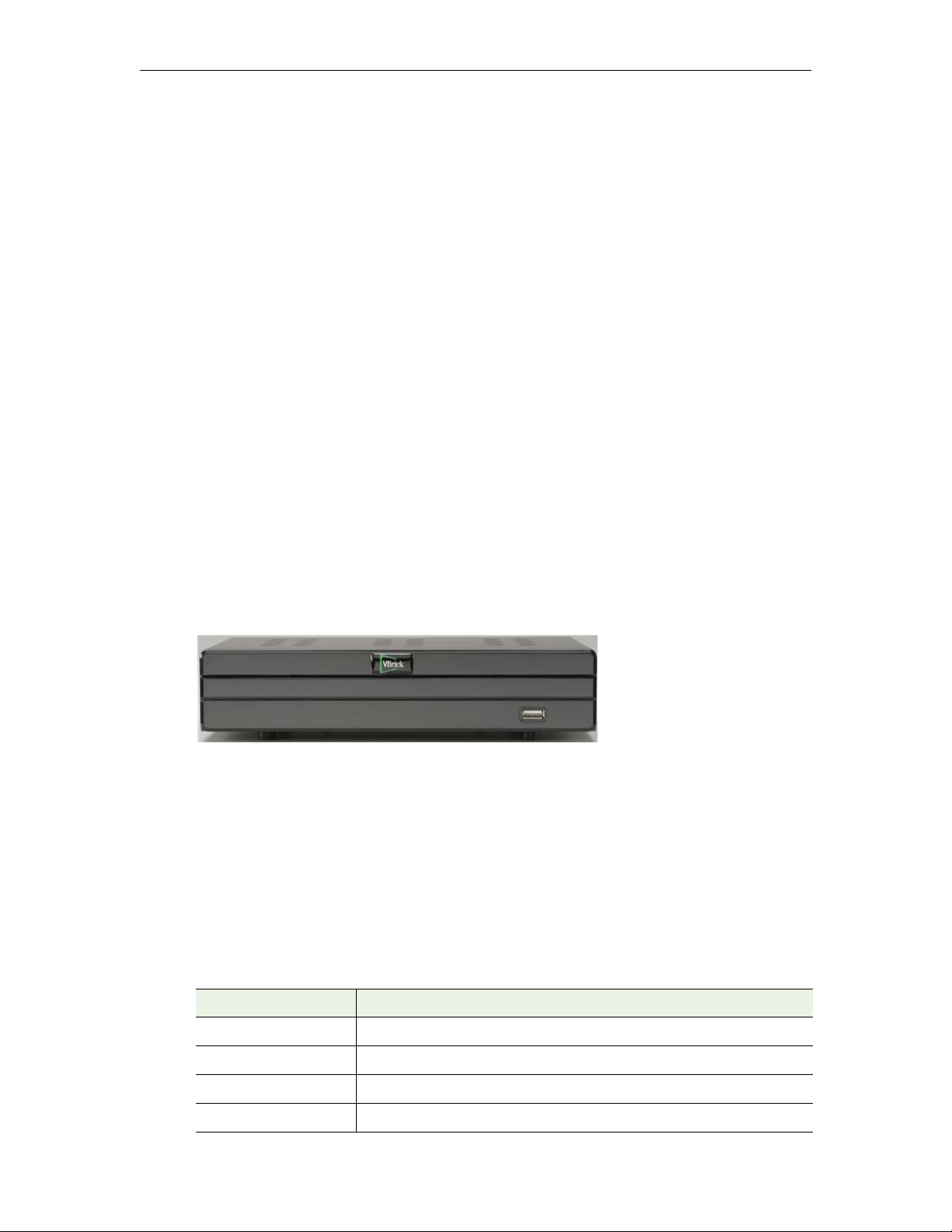
Figure 1. Multi-Format Set Top Box (front)
Creating STB Users
In a VEMS Mystro environment, each STB must be associated with a VEMS user and each
VEMS STB user must be unique. In large-scale deployments with hundreds of boxes, creating
these users is a time-consuming and error-prone manual process. The STB Users Utility is a
program that automates this process and automatically creates users and assigns them to each
STB in your environment. For an explanation of how to install and use this utility, see the
"STB Users Utility" topic in the Portal Server Admin Guide.
Table 1. Supported Stream Formats
Format Description
H.264 RTSP Interleaved, RTSP (Transport Stream and RTP)
Windows Media HTTP and RTSPU (ASF Format)
MPEG-2 Multicast, Unicast (Transport Stream)
MPEG-4 RTSP, RTSP Interleaved (RTP)
Multi-Format STB Quick Start 1
Page 8

Hardware Specifications
Table 2. Hardware Specifications
Video Decoder and
Transport Protocols
Network Connectivity 10/100 Base T
Video Outputs • NTSC 720x480 @ 30fps
Audio Outputs • Stereo audio
Front Panel Display • IR Window
Rear Panel • CVBS composite out (RCA jack yellow)
• Windows Media in ASF over HTTP
• H.264 in RTP and MPEG-2 Transport Stream
• MPEG-4 part 2 over RTP
• MPEG-2 over Transport Stream
• PAL 720x576 @ 25fps
• HD Outputs: 720p and 1080i
• HDMI, Component Video, S-Video, and Composite Video
• Resolutions up to 1920x1080
• Embedded audio on the HDMI interface
• LAN connectivity monitor LED
• Component out (RCA jacks green, blue, and red)
• Audio out port (RCA jack white, red)
• RJ-45 LAN port
• USB port for keyboard
• HDMI
IR Interface Yes
Dimensions L 9.4in x D 6in x H 2.2in (L 23.9cm x D 15.2cm x H 5.6cm)
Power Supply 18W
Weight 1.8 lbs
Regulatory Approvals FCC Part 15, CE
Operating Range • Temperature from 0 to 40C
Installation
The Multi-Format Set Top Box is shipped with Audio/Video, S-Video, Ethernet, and power
cables. It also has a handheld IR remote control unit with batteries. Connect the STB to a
standard or high definition TV as explained below. Check the components for damage as you
unpack the device and contact VBrick if anything is missing or damaged. Use common sense
when installing the set top box. Do not expose the unit to direct sunlight, high humidity or wet
conditions. Do not block the air vents or impede the airflow in any way.
• Humidity 5% ~ 95%
2 © 2016 VBrick Systems, Inc.
Page 9
Getting Started
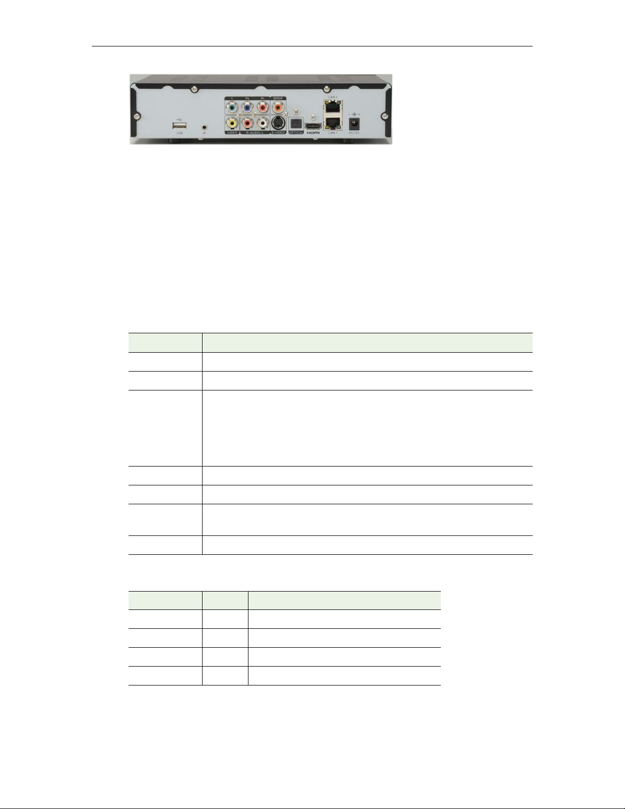
Figure 2. Multi-Format Set Top Box (rear)
To setup and connect the Multi-Format STB:
1. Place the device in a suitable location.
2. Connect the device to your network using the provided Ethernet cable with an RJ-45
connector.
3. Connect the STB to the display device(s). You can output to multiple standard or high
definition devices using the composite, component, or HDMI connectors.
4. Connect the audio outputs as necessary.
5. Connect the power supply to the STB and install two AAA batteries in the remote
control.
Table 3. Rear Panel Connectors
Connector Description
USB port Use to connect a USB keyboard.
IR Supports an IR extender for the remote control.
A/V Output • Y, Pb, Pr – component connectors.
• SPDIF – used with 5-in-1 audio cable.
• VIDEO – composite connector.
• R-AUDIO-L – left/right audio out.
• S-VIDEO – S-Video connector.
Optical Not used.
HDMI HDMI output. Connect to an HDMI-compatible TV.
LAN1/LAN2 Use LAN 1 to connect to your Ethernet network. LAN 2 can be used as a
second network connection but may impact performance.
DC12V Connect to power supply.
Table 4. Front Panel LEDs (left to right)
LED Color Description
Standby Red Flashes red when power is applied.
Power Green Steady green when power is applied.
Link Green Steady green when power is applied.
IR Remote Red Flashes red when using IR remote control.
Multi-Format STB Quick Start 3
Page 10
Start Mode
The Start Mode indicates how the set top box is populated with channel content. It
determines the look-and-feel of the interface and controls which channels are displayed and
available for viewing.
Mode.
Table 5. STB Start Modes
Start Mode Description
Local Host the channel guide directly on the set top box using channels.xml.
Server Populate the channel guide from VEMS. Enter the IP address or hostname
Other Host the channel guide on local PC using the IIS server. Enter the IP
Local Mode
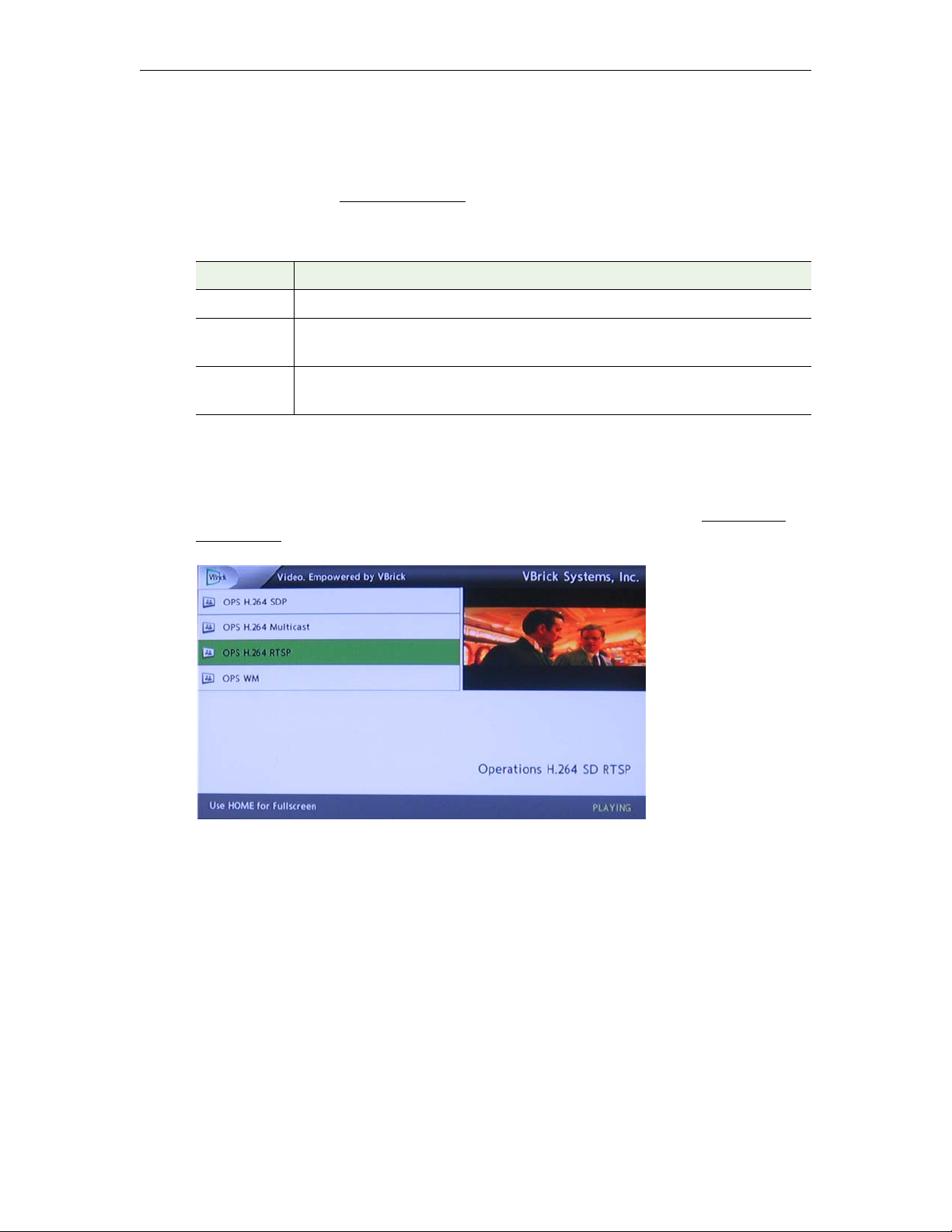
In Local Mode the Multi-Format STB plays "channels" that are hard-coded in an .xml file and
FTPed to the STB. The box will then display a "channel guide" as shown in Figure 3. Local
Mode (or Local Fullscreen Mode) is configured in the channels.xml file. See
channels.xml on page 17 for details.
STB Configuration on page 10 explains how to configure the Start
of the VEMS server. Use https in the URL to configure for SSL.
address/URL pointing to the location of the pages.
Configuring
Figure 3. Local Mode
Local Fullscreen Mode
In Local Fullscreen Mode the set top box plays one channel that fills the entire screen. A set
top box configured for Full Screen Mode is shown in Figure 4. Local Fullscreen Mode is
configured in the channels.xml file.
4 © 2016 VBrick Systems, Inc.
Page 11
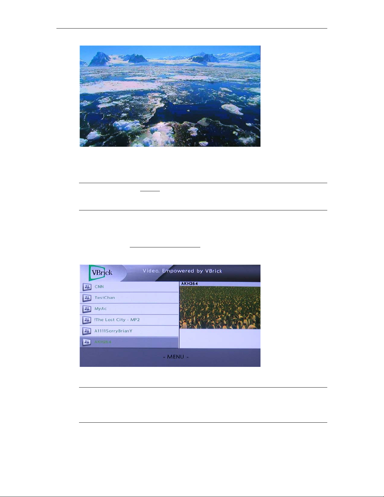
Figure 4. Local Fullscreen Mode
Portal Server Mode (VEMS 5.x)
Getting Started
Note As noted in the
Preface, there are important differences in behavior depending on
whether you are using the set top box with a VEMS 5.x system or with a VEMS 6.x
system. Whenever there is a difference in behavior, it will be noted in the text.
In Portal Server Mode the set top box has a complete "channel guide" populated by the
VEMS Portal Server. The channel guide displays both live streams and stored streams from a
VOD server. You will typically use the handheld Remote Control to navigate through various
menu options (see
Using the Remote Control on page 41 for more about using this device).
You can also connect and use a USB keyboard.
Figure 5. Portal Server Mode (VEMS 5.x)
Note In Portal Server Mode you may be prompted for a PIN when the set top box is
powered on or rebooted. PIN numbers are enabled by default and are assigned to each
user in VEMS. To change or disable the PIN, see Users > Add /Modify User
Information in the Portal Server Admin Guide.
In Portal Server Mode all live and stored content is hosted from the Portal Server and the
MENU button provides a subset of Portal Server functionality. To display menu options,
Multi-Format STB Quick Start 5
Page 12
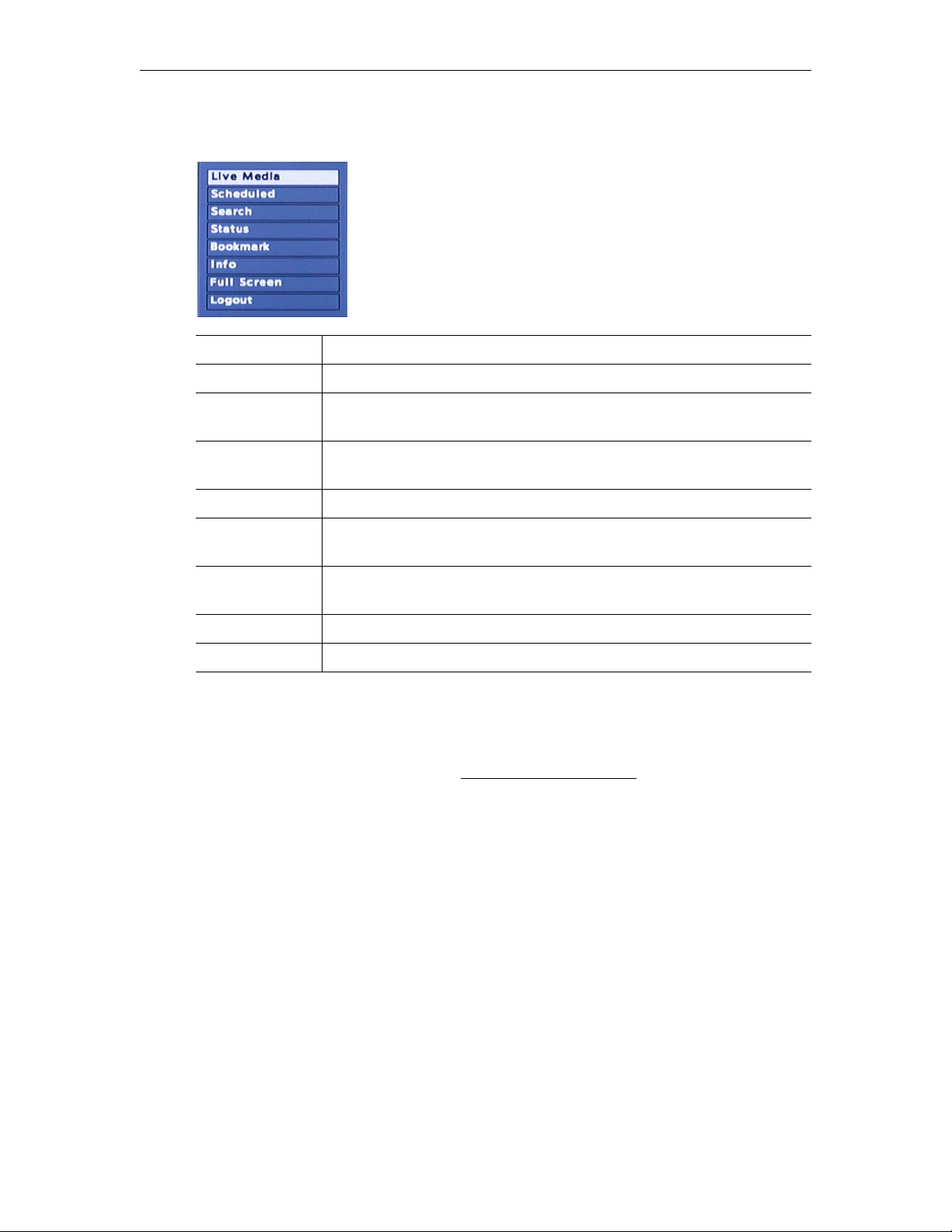
click the MENU button on the remote control. Click MENU again to hide menu options. Note
that the items shown on the menu vary depending on which page is currently displayed.
Live Media Goes to the top level of the Live Media pages.
Scheduled Displays any scheduled programs currently available for viewing.
Media Library Goes to the top (root) level of the Media Library. Click on any folder to
display the contents of the folder. Click Up to return to previous display.
Search Lets you search for media by Title, Tags, Description, or Custom Fields
created by a VEMS administrator.
Status Displays status info for any video ingestions currently in progress.
Bookmark Media Library. Use to bookmark any point in a stream. Click once to
start and once to stop and save.
Info Media Library. Displays Title, Description, and Keywords for any stored
stream in the library.
Full Screen Go to full screen. Click Full Screen on remote to exit.
Logout Stops streams, exits application, and displays login page.
Portal Server Mode (VEMS 6.x)
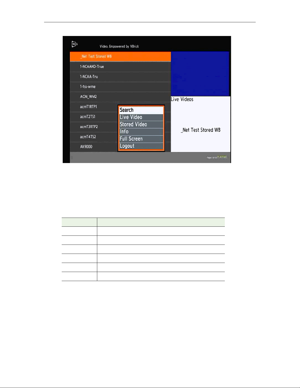
The set top box has different features and functionality when used with VEMS 6.x systems.
In VEMS 6.x you navigate and search using the labeled buttons on the remote control device.
These buttons are explained in detail in
summarized below in Table 6. You may be prompted for a PIN number when the set top box
is powered on or rebooted. PIN numbers are assigned to each user in VEMS. To change or
disable the PIN, see Access Control > Users in the Portal Server Admin Guide.
Using the Remote Control on page 41 and
6 © 2016 VBrick Systems, Inc.
Page 13
Getting Started
Figure 6. Portal Server Mode (VEMS 6.x)
In VEMS 6.x you perform a search using the
Search button on the remote control. You can
filter by category, type, or keyword (Figure 7) and any stream currently in progress will
continue to play when the search results are displayed. When paging through live or stored
video, press the
Live or VOD button to return to page one of the respective live or stored
pages.
Table 6. Remote Control Navigation (VEMS 6.x)
Button Description
Search Search for live or stored content.
Live Video Go to the Live Video page.
Stored Video Go to the Stored Video page.
Info Displays information about the currently selected stream.
Full Screen Go to full screen or exit full screen.
Logout Logout from the STB
Multi-Format STB Quick Start 7
Page 14
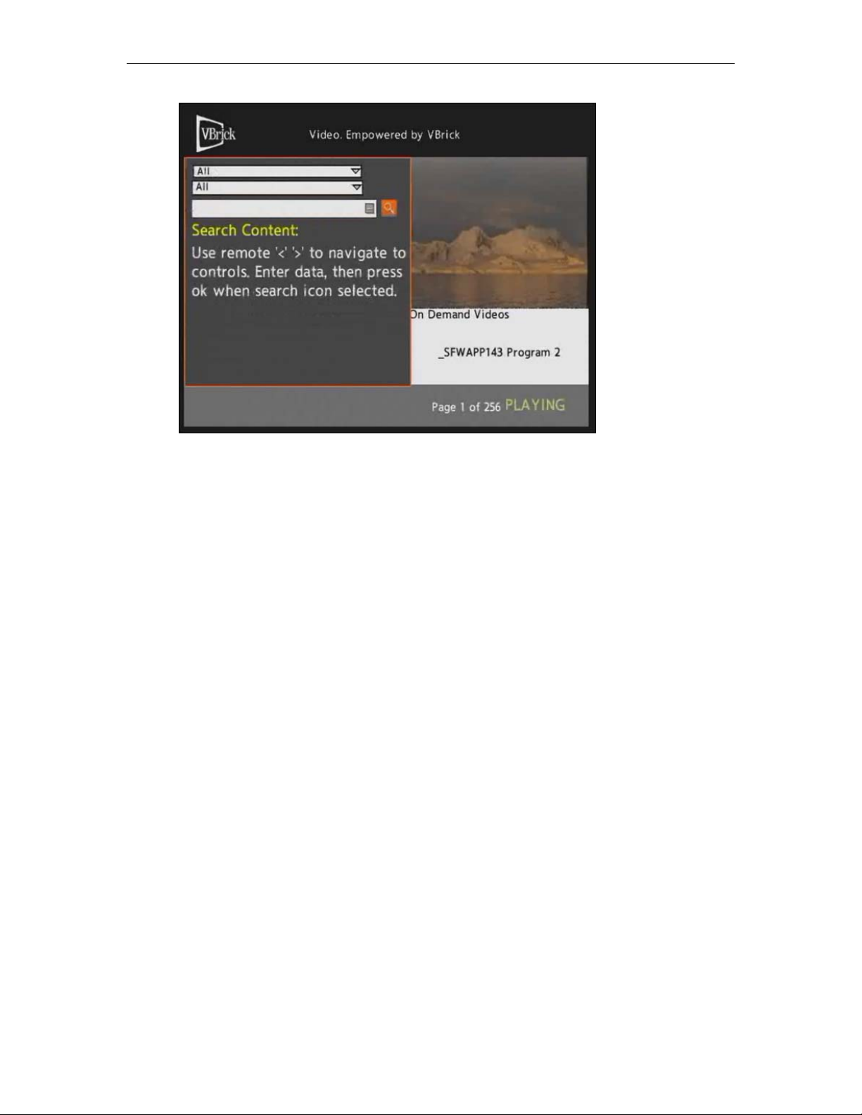
Figure 7. Search Live or Stored Content (VEMS 6.x)
8 © 2016 VBrick Systems, Inc.
Page 15
Configuration
Topics in this chapter
Displaying the Setup Page . . . . . . . . . . . . . . . . . . . . . . . . . . . . . . . . . . . . . . . . . . . . . . . . . . . .9
STB Configuration . . . . . . . . . . . . . . . . . . . . . . . . . . . . . . . . . . . . . . . . . . . . . . . . . . . . . . . . . 10
Upgrade, Reset, Change Password. . . . . . . . . . . . . . . . . . . . . . . . . . . . . . . . . . . . . . . . . . . . . 16
Displaying the Setup Page
The Setup pages are used to set various configuration options such as IP Address and Start
Mode. As shown in Table 7, different setup pages are displayed depending on the password
you enter.
To launch the Setup pages:
1. Connect the STB to the display device.
2. Power the STB off and on with the red power button on the remote control.
3. Wait until the VBrick logo is replaced by a black screen.
4. When the animated "Starting" circle is displayed, start pressing the
remote and continue until the Password page is displayed.
Chapter 2
Help (?) button on the
5. Enter the password corresponding to the pages you wish to edit.
Table 7. Setup Program Passwords
Password Use To ...
1234 Set IP Address, Start Mode, Video & Audio Output Setting, etc.
5678 Upgrade, Reset Factory Defaults, change Password.
Changing the IP Address
By default, the set top box is configured for DHCP (Dynamic Host Configuration Protocol)
and will automatically retrieve an IP address from a DHCP server if present. If a DHCP
server is not present or unavailable, you can configure the set top box with a static IP address
and other network options. If you have the VBDirectory management program installed you
easily find any networked VBrick devices. See
To find the IP address launch the Setup program as explained below or in Local Mode use
the remote control (use the unlabeled third button down on the right). Then move the cursor
to the Information icon in the lower left area of any page and click on the Info icon This will
display the IP Address, MAC Address, Firmware Version, and other data (see Figure 8). The
set top box is configured for DHCP by default and will automatically acquire an IP address
when plugged in if your network is DHCP-enabled.
VBDirectory on page 30 for more information.
Multi-Format STB Quick Start 9
Page 16
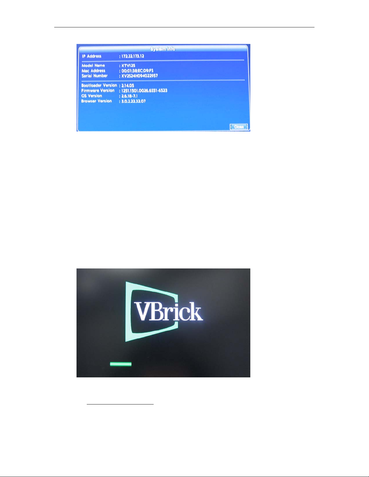
Figure 8. System Info page.
Setting a Static IP Address
To set a static IP address:
1. Launch the setup program (see below) to display the
2. Use the remote control to enter a static
DNS information. If in doubt, get this information from your system administrator.
and
3. When done navigate to
STB Configuration
This topic explains how to configure various STB parameters such as start mode and SD or
HD Output resolution.
To configure the set top box using the remote control:
1. Power up the box and wait for screen that looks like this.
IPv4 Network Setting page.
IP Address as well as Netmask, Default Gateway,
Finish and click OK on the remote control.
2. When the animated "Starting" circle is displayed, start pressing the Help (?) button on
the remote and continue until the Password page is displayed. (For more details see
Displaying the Setup Page on page 9.)
10 © 2016 VBrick Systems, Inc.
Page 17
Configuration
Note: Click the Info icon in the lower left area of the page to display the MAC address
and other information (see Figure 8) without entering a password.
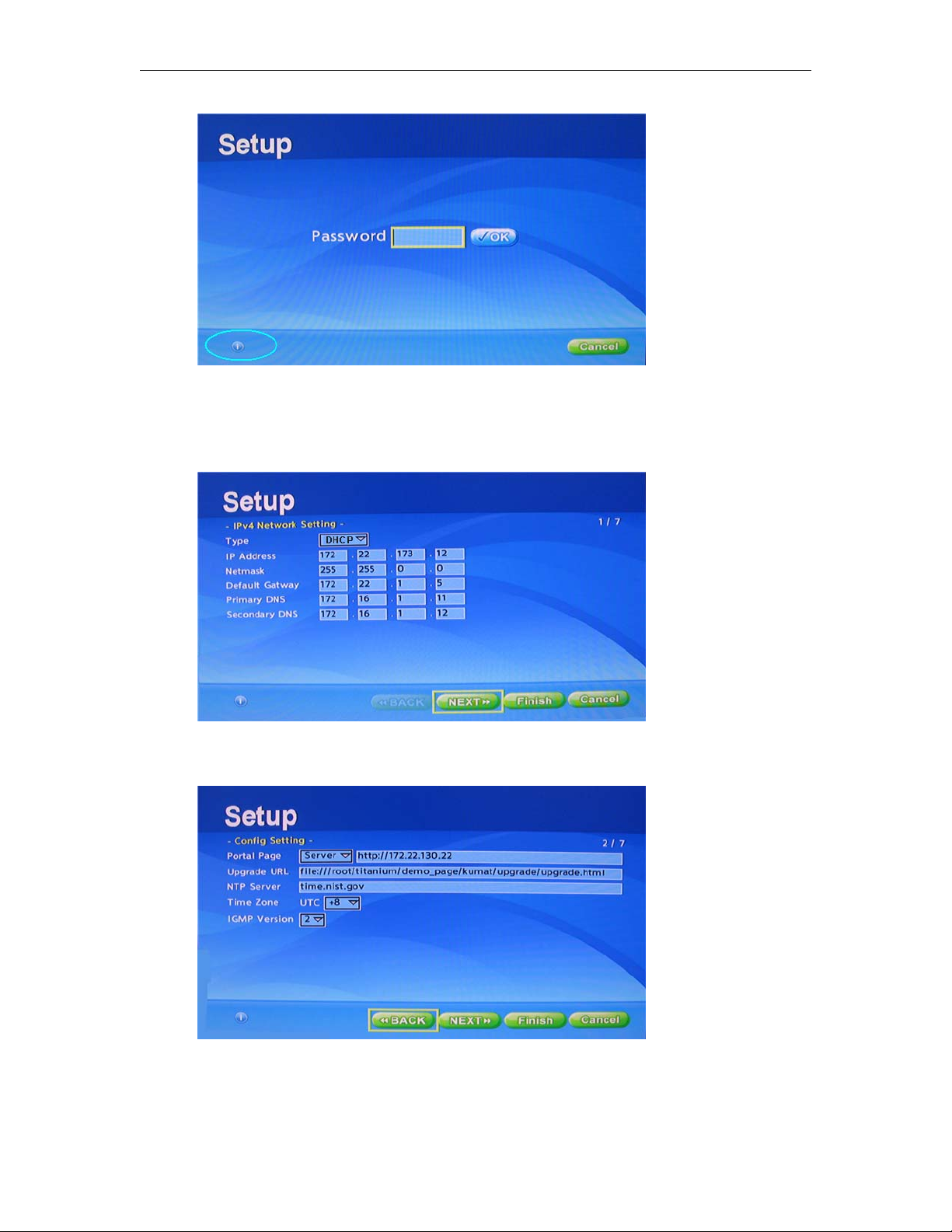
3. Enter the default password
1234, move the cursor to the OK button, and press the OK
button on the remote.
4. When the page shown above is displayed, move the cursor to
Next and press the OK
button on the remote control to continue. (Note that DHCP is enabled by default.)
Portal Page – Use this field to select the Start Mode (Local, Server, Other). See Table 5 on
5.
page 4 for more about these options. Use
https in the URL to configure the STB for
SSL. SSL applies when the STB is in Portal Server Mode only. When configured for SSL,
all management communication between the Portal Server and the STB is encrypted. To
Multi-Format STB Quick Start 11
Page 18
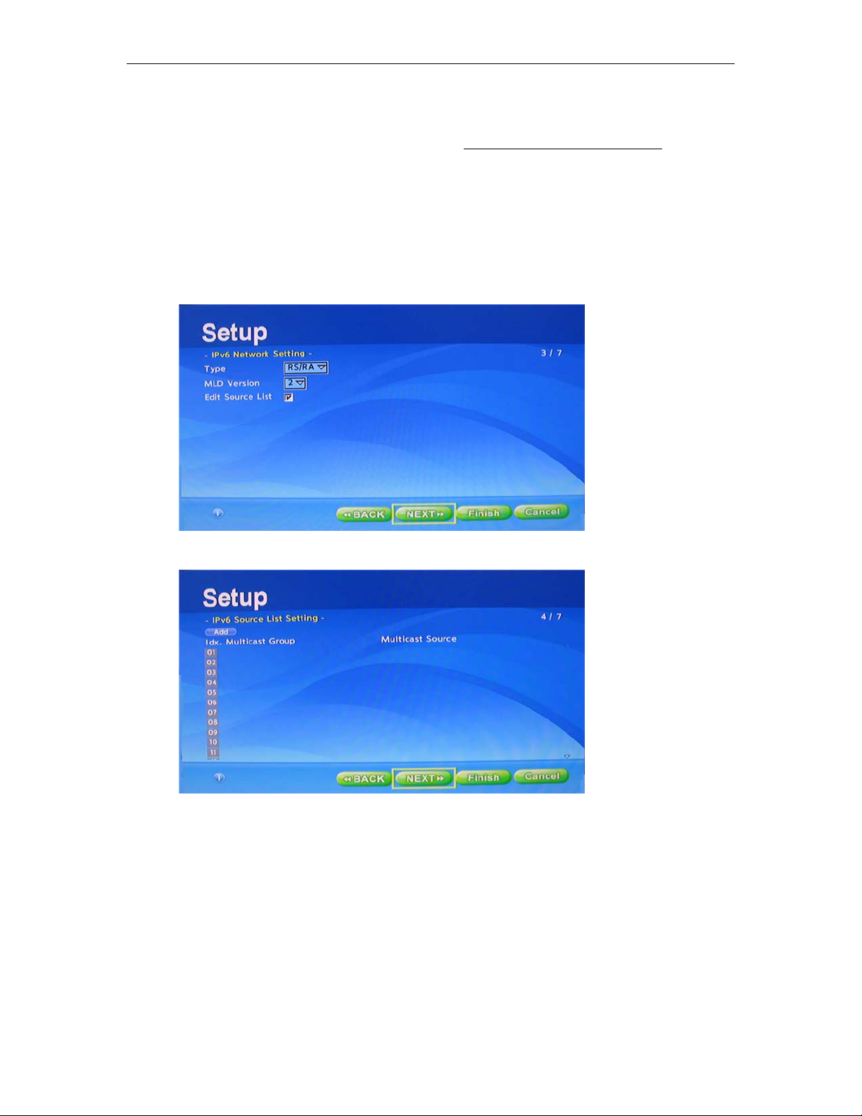
implement SSL you will also need to configure SSL on the Portal Server. If SSL is
enabled and there is no root certificate, you can disable validation (and eliminate the
warning pop-up) in the
config.txt file. See Setting Configuration Parameters on page 49
for more about this.
Upgrade URL – 6.x only. Use this field to take advantage of the upgrade server. Each time
the unit starts it checks this location for software updates. If you do not have an upgrade
server (and do not plan to have one), leave this field blank. If this field is populated by an
offline server, the unit will make 5 attempts to connect and then bypass the upgrade step.
6. Set UTC to your local time zone. (U.S. Eastern Time = -5)
7. Click
Next to continue.
8. Click
9. Click
Next to continue.
Next to continue.
12 © 2016 VBrick Systems, Inc.
Page 19
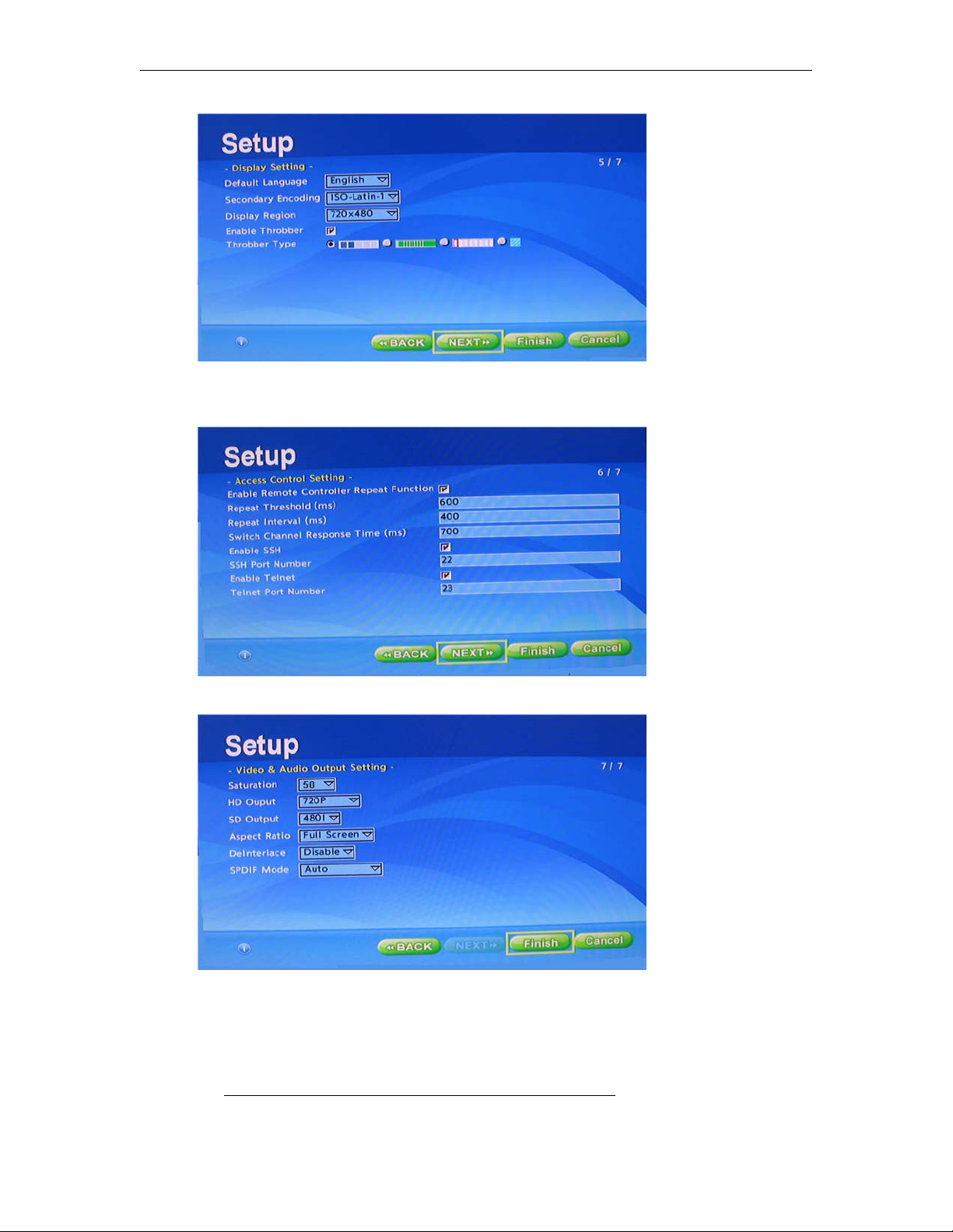
Configuration
10. Click Next to continue. (Note: the Display Region is used for Channel Guide graphics—
not the video resolution. The 640x480 setting may not work properly on some screens.)
11. Click
12. On the
Next to continue.
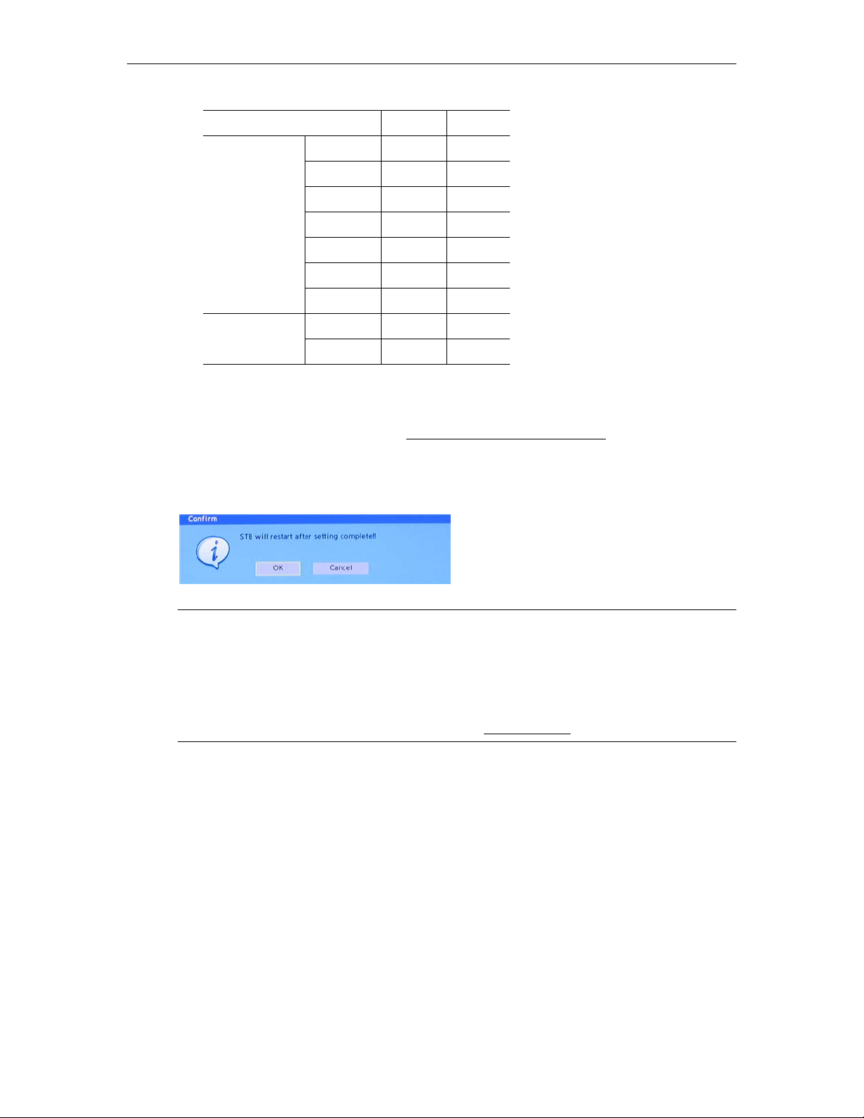
Video & Audio Output Setting page, set HD Output and SD Output to match the
display device(s) you have connected to the set top box. You can have multiple devices
(for example composite and HDMI) but the HD and SD outputs must match; that is
they must both be NTSC or must both be PAL. Refer to the table below; do not mix and
match modes. (If necessary you can also fine tune the display area for set top boxes; see
Adjusting the Display Area of Output Devices (VEMS 5.x) on page 14 for details.)
Multi-Format STB Quick Start 13
Page 20
NTSC PAL
HD Output 1080P30 x
1080P24 x
1080i x
1080i50 x
720P * x
720P50 x
576P x
SD Output 480i x
576i x
Default
*
You can also set the display area and other parameters by modifying the config.txt file,
either manually or via Telnet (see
example, the
Video/Audio Output Setting section lets you modify saturation, contrast,
Setting Configuration Parameters on page 49). For
hue, brightness, and aspect ratio.
13. Click
Finish and then OK to save your changes and reboot.
Note At STB startup, HDMI output format is based on the EDID signalling between the
TV and the STB. If the TV does not report that it supports 1080P, the STB will fall
back to a lower resolution. In some cases you may wish to force 1080P regardless of
the EDID signalling. This will support TVs that play 1080P but do not perform EDID
signalling correctly. To force output to 1080p, set the following parameter in
data/config.txt: stb.hdmi.validate_edid_format: 0 (This parameter is in the
"Video/Audio Output Setting" section. See
Config.txt File on page 50.)
/root/
Adjusting the Display Area of Output Devices (VEMS 5.x)
VEMS 5.4 or higher. If necessary, you can fine tune the channel guide graphics display area
for output devices (i.e. monitors) connected to each set top box in your network. You can
shrink the display area of the output by up to 20 per cent to match the unique specifications
of each monitor. This does not affect the full screen size of the video—it only affects the
channel listing and VEMS page display.
Portal Server Mode
You can adjust the display area of output devices by modifying the adjust.xml file in VEMS.
This file is located in the following folder on the VEMS Portal Server:
C:\Program Files\VBrick\MCS\VEMSPisces\adjust.xml
14 © 2016 VBrick Systems, Inc.
Page 21

Configuration
To fine tune the display area for connected devices:
1. Open
adjust.xml in a text editor such as Notepad.
2. Add one line for each Multi-Format Set Top Box you wish to fine tune. This line must
contain an XML tag containing the MAC address of the box and an adjustment value in
the range of 1–20 per cent. For example if the set top box has an MAC address of
38-EC-D9-D1 and requires a screen adjustment (shrinkage) of 5 per cent, the tag entry for
00-01-
that device would be:
<MAC00-01-38-EC-D9-D1>5</MAC00-01-38-EC-D9-D1>
The MAC address format is six groups of two digit hexadecimal numbers separated by
either hyphens ("-") as above or by colons (":"). If colons were used as a separator in the
above address it would be written
00:01:38:EC:D9:D1
The XML document specification does not allow multiple sequential colons to be used in
an XML tag. To use a colon-separated MAC address as an adjustment tag simply replace
the colons with hyphens when forming the tag so that it looks like the example above.
3. Add one tag for each additional set top box that needs adjustment.
4. Reboot the server when done.
Local Mode
You can adjust the channel guide graphics display area of an output device so that the entire
output is shown on the monitor by modifying the
folder, lets you scale the channel listing graphic to match the size of your TV. On certain TV
sets, the image can be chopped of by the bezel, causing a loss of graphic imagery. You can
adjust the value in terms of screen percentage. The default is 10, meaning that the graphic
image will be reduced by 10%. Be aware that all TV’s are not alike. Values that work on some
TV's may not work well on others, even the same brand. A setting of 0 is maximum size.
Valid ranges are from 0 to 20. Please note that this setting does not affect the size of full
screen video. Depending on how your system is configured, this file is located on the set top
box or on a VEMS server.
adjust.xml file. This file, found in the data
To modify the display area of an output device:
1. Navigate to
root\data\adjust.xml using Telnet or FTP. (See Updating channels.xml on
page 22 for instructions that explain how to access this file.)
2. Open the file in Notepad or a similar editor.
3. Enter a percentage value for the amount of shrinkage (range = 0–20). For example, set to
5 to shrink the display area by 5 percent.
<STBLocalParms>
<Adjust>5</Adjust>
</STBLocalParms>
4. Save the file and exit when done.
Adjusting the Display Area of Output Devices (VEMS 6.x)
If necessary, you can fine tune the channel guide graphics display area for output devices (i.e.
monitors) connected to each set top box in your network. You can shrink the display area of
the output by up to 20 per cent to match the unique specifications of each monitor. Note that
to use this procedure, the STB must be configured in VEMS as explained in the Portal Server Admin
Guide.
Multi-Format STB Quick Start 15
Page 22
Portal Server Mode
To adjust the display area of an output device.
1. Login to the VEMS 6.x Admin interface:
2. Go Devices > STB and modify the
Screen Adjustment parameter as necessary. The range
is 1–20. A value of 5 will shrink the display area by 5 percent.
Local Mode
See Local Mode above. The instructions are the same for VEMS 5.x and VEMS 6.x.
Upgrade, Reset, Change Password
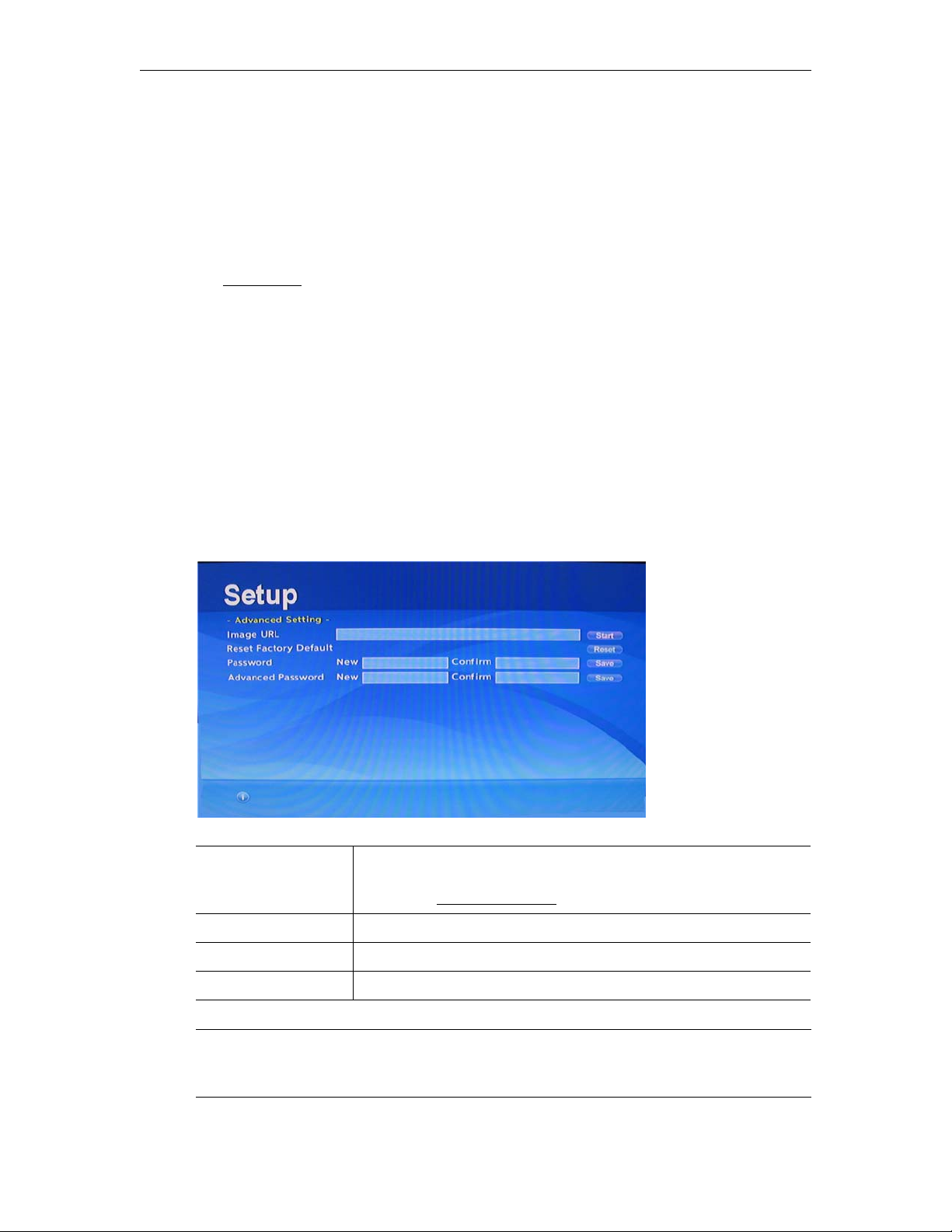
Use the setup pages to perform standard housekeeping tasks. These include Reset, Upgrade,
Change Password, etc. To reboot, simply power the device off/on with the
the remote control.
To reset, upgrade, change password, etc.
1. Power the device off/on with the
2. When the animated "Starting" circle is displayed, start pressing the
remote and continue until the Password page is displayed
3. Enter the default password
on the remote control), and press the
Power button on the remote control.
5678, move the cursor to the OK button (using the arrow keys
OK button on the remote.
Power button on
Help (?) button on the
Image URL Upgrade the set top box. Enter the path to upgrade image file
(using FTP or HTTP) and press
option, see
Software Upgrade on page 33.
Reset Factory Default Reset box to factory defaults. Click
Start. For more about using this
Reset.
Password Change "basic" Setup password. Default = 1234. See note below.
Advanced Password Change "advanced" Setup password. Default = 5678
Note After changing the password, be sure to save the new password in a safe and accessible
location. If you lose the password your warranty may not cover the cost of shipping
the unit to VBrick for repair and unlocking.
16 © 2016 VBrick Systems, Inc.
Page 23
Creating a Channel Guide
Topics in this chapter
Overview . . . . . . . . . . . . . . . . . . . . . . . . . . . . . . . . . . . . . . . . . . . . . . . . . . . . . . . . . . . . . . . . 17
Configuring channels.xml. . . . . . . . . . . . . . . . . . . . . . . . . . . . . . . . . . . . . . . . . . . . . . . . . . . .17
Updating channels.xml. . . . . . . . . . . . . . . . . . . . . . . . . . . . . . . . . . . . . . . . . . . . . . . . . . . . . .22
Hosting channels.xml on a PC. . . . . . . . . . . . . . . . . . . . . . . . . . . . . . . . . . . . . . . . . . . . . . . . 23
Using Multiple channel.xml Files. . . . . . . . . . . . . . . . . . . . . . . . . . . . . . . . . . . . . . . . . . . . . . 25
Overview
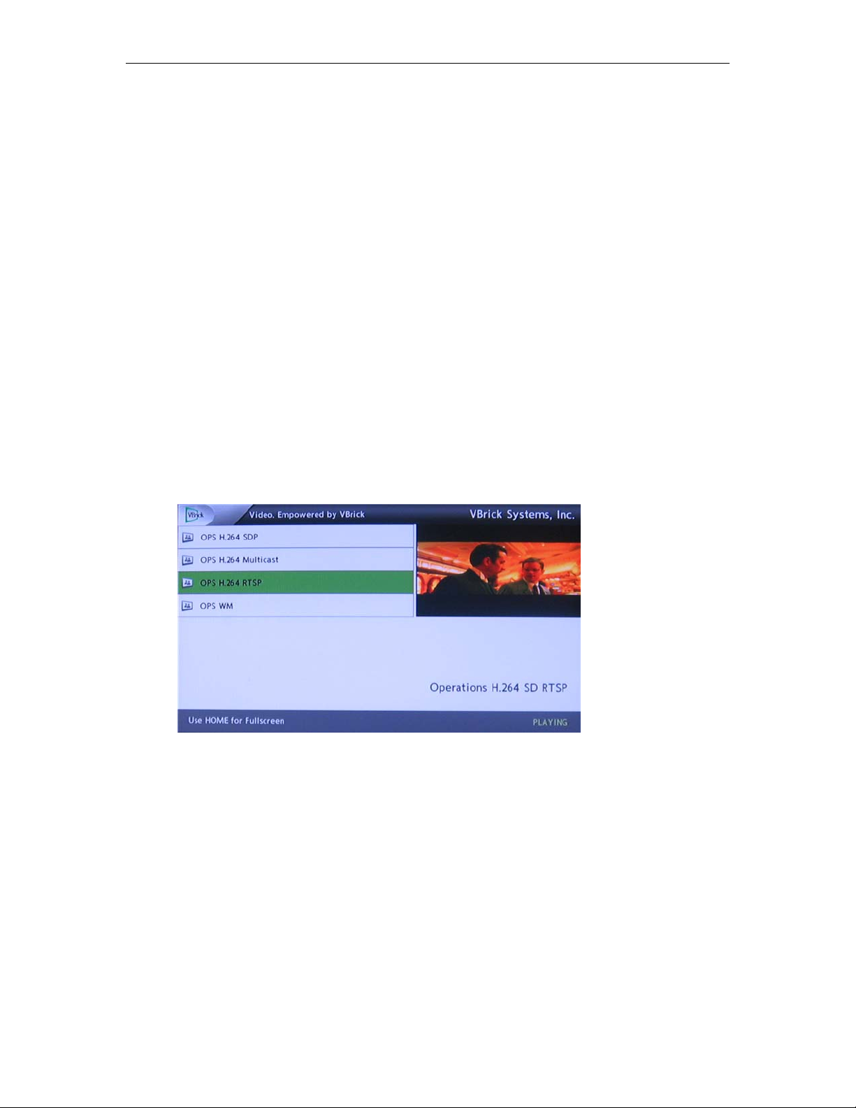
A local channel guide like the one in Figure 9 is created by configuring an .xml file with the
desired channels and FTPing it to the set top box. You can also host the required STB files
on a PC. To host the files on a PC you will need to configure Windows for IIS and then use
your PC to host the STB files with a URL similar to this:
http://local_pc_ipaddr/home.htm
Chapter 3
Figure 9. Local Mode Channel Guide
Configuring channels.xml
The following code shows the channels.xml file that is used to create the channel guide.
There is a file header and separate section for each stream. Modify this file so that the IP
addresses, port numbers, and messages reflect the actual streams you have available at your
site. Cut and paste as necessary to add new streams and be sure to delete any unused streams.
Note that no extra spaces are allowed and there is only one blank line between channel
definitions. This file has a limit of 99 defined channels. As a best practice, it is always a
good idea to make a backup copy of this file.
Multi-Format STB Quick Start 17
Page 24

Table 8. Channels.xml File Entries
Parameter Description
Title
GlobalMsg
Fullscreen
Company title on upper right screen. See Figure 9.
Message displayed under preview window.
Set to 0 for Local Mode and 1 for Local Fullscreen Mode.
Launches the default stream (see below).
ProgramName
Stream title (and number) displayed in the program guide for each
channel and/or full screen window.
Message
Text displayed in lower-right message area under the preview
window.
URL
RTSP
– Real Time Streaming Protocol. Commonly used with
streaming media servers.
RTSPU – RTSP with UDP.
HTTP – point to a live or stored stream.
MCAST – multicast address using an .nsc file.
tv
DfltStrm
Used with H.264 or MPEG2 Transport Streams.
Set to x to specify the default stream. See example below. This is
the stream that will play in the specified mode (Local or Local
Fullscreen) when the set top box is powered on.
Sample Channels File
The following code shows a sample channels.xml file. This file contains multiple
"paragraphs" and each is used to define a specific encoding and stream type. The idea is to
find the paragraph that matches your stream type and to copy and paste that paragraph
multiple times to create as many menu line items as you need. Be sure to delete any
unnecessary paragraphs. Any extra paragraphs that reference nonexistent or inoperative streams will
still appear in the local channel guide but will fail to start a working stream. Note below that the
Windows Media HTTP Live channel definition uses the DfltStrm parameter to define to the
default channel.
<?xml version="1.0" encoding="utf-8"?>
<STBLocalUI>
<!-- this is general information -->
<Title>VBrick Systems, Inc.</Title>
<GlobalMsg></GlobalMsg>
<FullScreen>0</FullScreen>
<!-- RTSP MPEG4 Interleave -->
<Stream>
<ProgramName>RSTP MPEG4 Interleave (server session based)</ProgramName>
<Message>rtsp://172.22.123.116/unit116s2?tcp=1</Message>
<URL>rtsp://172.22.123.116/unit116s2?tcp=1</URL>
</Stream>
<!-- RTPS MPEG4 Live -->
<Stream>
<ProgramName>RSTP MPEG4 Live (server session based)</ProgramName>
18 © 2016 VBrick Systems, Inc.
Page 25

<Message>rtsp://172.22.123.116/unit116s2</Message>
<URL>rtsp://172.22.123.116/unit116s2</URL>
</Stream>
<!-- MPEG4 Multicast SDP -->
<Stream>
<ProgramName>MPEG4 Multicast SDP</ProgramName>
<Message>http://172.22.123.116/vbs2d1.sdp</Message>
<URL>http://172.22.123.116/vbs2d1.sdp</URL>
</Stream>
<!-- MPEG2 Multicast Live -->
<Stream>
<ProgramName>MPEG2 Multicast Live</ProgramName>
<Message>tv://239.16.2.180:4444</Message>
<URL>tv://239.16.2.180:4444</URL>
</Stream>
<!-- H.264 RTP RTSP -->
<Stream>
<ProgramName>H.264 RTP RTSP</ProgramName>
<Message>rtsp://172.22.128.1/vbStream1S1</Message>
<URL>rtsp://172.22.128.1/vbStream1S1</URL>
</Stream>
Creating a Channel Guide
<!-- H.264 TS Multicast -->
<Stream>
<ProgramName>H.264 TS Multicast</ProgramName>
<Message>tv://239.22.128.1:4444</Message>
<URL>tv://239.22.128.1:4444</URL>
</Stream>
<!-- H.264 TS Unicast -->
<Stream>
<ProgramName>H.264 TS Unicast</ProgramName>
<Message>tv://<local_ip_address>:4444</Message>
<URL>tv://<local_ip_address>:4444</URL>
</Stream>
<!-- H.264 TS RTSP -->
<Stream>
<ProgramName>H.264 TS RTSP</ProgramName>
<Message>rtsp://172.22.128.1/vbStream1S2</Message>
<URL>rtsp://172.22.128.1/vbStream1S2</URL>
</Stream>
<!-- Windows Media RTSPU -->
<Stream>
<ProgramName>WM RTSPU</ProgramName>
<Message>rtspu://172.22.2.171/vbrickvideo1</Message>
<URL>rtspu://172.22.2.171/vbrickvideo1</URL>
</Stream>
<!-- Windows Media HTTP -->
<Stream>
Multi-Format STB Quick Start 19
Page 26

<ProgramName>WM HTTP</ProgramName>
<Message>http://172.22.2.171:8080/vbrickvideo1</Message>
<URL>http://172.22.2.171:8080/vbrickvideo1</URL>
</Stream>
<!-- Windows Media Multicast NSC -->
<Stream>
<ProgramName>WM Multicast NSC</ProgramName>
<Message>mcast://172.22.2.171/vbs1multi.nsc</Message>
<URL>mcast://172.22.2.171/vbs1multi.nsc</URL>
</Stream>
<!-- Windows Media HTTP Live -->
<Stream>
<ProgramName>OPS WM</ProgramName>
<Message>http://172.17.120.111:8080/vbrickvideo1</Message>
<URL>http://172.17.120.111:8080/vbrickvideo1</URL>
<DfltStrm>x<DfltStrm>
<!-- H.264 VODW TS RTSP -->
<Stream>
<ProgramName>H.264 VODW TS RTSP</ProgramName>
<Message>rtsp://172.22.2.119/CD-H264.mp4</Message>
<URL>rtsp://172.22.2.119/CD-H264.mp4</URL>
</Stream>
<!-- H.264 VODW RTP RTSP -->
<Stream>
<ProgramName>H.264 VODW RTP RTSP</ProgramName>
<Message>rtsp://172.22.2.119/Bob-H264-RTP.mp4</Message>
<URL>rtsp://172.22.2.119/Bob-H264-RTP.mp4</URL>
</Stream>
<!-- MPEG4 VODW RTSP -->
<Stream>
<ProgramName>MPEG4 VODW RTSP</ProgramName>
<Message>rtsp://172.22.2.119/CD-MPEG4.mp4</Message>
<URL>rtsp://172.22.2.119/CD-MPEG4.mp4</URL>
</Stream>
<!-- MPEG2 VODW RTSP -->
<Stream>
<ProgramName>MPEG2 VODW RTSP</ProgramName>
<Message>rtsp://172.22.2.119/AndyM-MP2.mpg</Message>
<URL>rtsp://172.22.2.119/AndyM-MP2.mpg</URL>
</Stream>
<!-- Windows Media VODWM RTSPT -->
<Stream>
<ProgramName>WM VODWM RTSP</ProgramName>
<Message>rtspt://172.17.2.44/PublishingPoint34</Message>
<URL>rtspt://172.17.2.44/PublishingPoint34</URL>
</Stream>
<!-- Windows Media VODWM RTSPU -->
20 © 2016 VBrick Systems, Inc.
Page 27

Creating a Channel Guide
<Stream>
<ProgramName>WM VODWM RTSPU</ProgramName>
<Message>rtspu://172.17.2.44/PublishingPoint34</Message>
<URL>rtspu://172.17.2.44/PublishingPoint34</URL>
</Stream>
<!-- Windows Media VODWM HTTP -->
<Stream>
<ProgramName>WM VODWM HTTP</ProgramName>
<Message>http://172.17.2.44/VBP/bobWM-LAN-1M.wmv</Message>
<URL>http://172.17.2.44/VBP/bobWM-LAN-1M.wmv</URL>
</Stream>
<!-- MPEG4 Darwin RTSP -->
<Stream>
<ProgramName>MPEG4 Darwin RTSP</ProgramName>
<Message>rtsp://172.22.2.117/Acacia/ACM%20H264_12_29_10_11_24_29.mp4</Message>
<URL>rtsp://172.22.2.117/Acacia/ACM%20H264_12_29_10_11_24_29.mp4</URL>
</Stream>
<!-- MPEG2 or H.264 Transport Stream file playback -->
<Stream>
<ProgramName>Playback .mpg Transport stream file from my PC 172.16.2.204</
ProgramName>
<Message>Playing content via httptv://172.16.2.204/mpeg2test.mpg</Message>
<URL>httptv://172.16.2.204/mpeg2test.mpg</URL>
</Stream>
</Stream>
</STBLocalUI>
Sample URLs
The following table shows sample URLs for different encoding formats and transport types.
Table 9. Sample URLs
MPEG2 Multicast Live
MPEG2 VOD-W RTSP
RTSP MPEG-4 Interleave
(server session based)
RTSP MPEG-4 Live
(server session based)
MPEG4 Multicast SDP
MPEG4 VOD-W RTSP
MPEG-4 Darwin RTSP
H.264 RTP RTSP
H.264 TS Multicast
H.264 TS Unicast
tv://239.16.2.180:4444
rtsp://172.22.2.119/AndyM-MP2.mpg
rtsp://172.22.123.116/unit116s2?tcp=1
rtsp://172.22.123.116/unit116s2
http://172.22.123.116/vbs2d1.sdp
rtsp://172.22.2.119/CD-MPEG4.mp4
rtsp://172.22.2.117/Acacia/
ACM%20H264_12_29_10_11_24_29.mp4
rtsp://172.22.128.1/vbStream1S1 (where vbStream1S1
points to RTP)
tv://239.22.128.1:4444
tv://172.22.2.19:4444
Multi-Format STB Quick Start 21
Page 28

H.264 TS RTSP
H.264 SDP RTP
(multicast or unicast)
H.264 VOD-W TS RTSP
H.264 VOD-W RTP RTSP
Window Media RTSPU
Window Media HTTP
Window Media Multicast NSC
Window Media VOD-WM RTSPT
Window Media VOD-WM RTSPU
Window Media VOD-WM HTTP
MPEG2 or H.264 Transport
Stream file playback
Updating channels.xml
There are basically two ways to change the channels.xml file. First, if you have created a valid
channels.xml file and placed it onto an accessible FTP server, you can go to the STB and
wget the file from the FTP server. Second, you can Telnet into the box and edit the text file in
place using vi.
rtsp://172.22.128.1/vbStream1S2 (where vbStream1S2
points to TS)
http://172.22.123.116/vbStream1S1.sdp
rtsp://172.22.2.119/CD-H264.mpg
rtsp://172.22.2.119/Bob-H264-RTP.mp4
rtspu://172.22.2.171/vbrickvideo1
http://172.22.2.171:8080/vbrickvideo1
mcast://172.22.2.171/vbs1multi.nsc
rtspt://172.17.2.44/PublishingPoint34
rtspu://172.17.2.44/PublishingPoint34
http://172.17.2.44/VBP/bobWM-LAN-1M.wmv
httptv://172.16.2.204/mpeg2test.mpg
Using wget
This method requires an FTP server. You can start by editing channels.xml file, creating the
desired list of channels, and saving it as
my_channels.xml. Then FTP the file to the VEMS
Portal Server for example, or to another FTP server.
To wget the file from an FTP server:
1. Telnet or SSH into the STB. When logging in, the user name is
settopbox.
# cd /root/data
# mv channels.xml YYYYMMDDchannels.xml
(to rename file to today's date as a backup)
iptv; the password is
or
# rm channels.xml (to simply delete the existing channels.xml file)
# wget ftp://<portal_server_ip_address>/My_channels.xml
# mv My_channels.xml channels.xml
# sync ; sleep 2 ; reboot
Using vi
This method explains how to edit the channels.xml file directly on the set top box using vi (a
screen-based Unix editor). For a list of vi commands go to
helpdocs/vi.html.
To edit the file in place with vi:
1. Telnet or SSH into the STB. When logging in, the user name is
settopbox).
http://www.cs.colostate.edu/
iptv; the password is
22 © 2016 VBrick Systems, Inc.
Page 29
# cd /root/data
# cp channels.xml YYYYMMDDchannels.xml
# vi channels.xml
(to rename file to today's date as a backup)
2. Navigate and edit the file using vi.
3. After editing the file, save and quit the vi session:
a. Press
b. To quit without saving type
Esc :wq
:q!
4. Reboot the STB:
# sync ; sleep 2 ; reboot
Hosting channels.xml on a PC
In order to greatly simplify changes to channels.xml on all of the set top boxes in your
network, you may want to host the required STB files on a PC. To do this you will need to
configure Windows for IIS and then use your PC to host the STB files. When the channels
file changes (for example if you add or change streams), you simply update the file in
c:\inetpub\wwwroot as explained below and reboot the set top box(es). The set top boxes
will then read the channels file from the PC.
Creating a Channel Guide
Configuring a PC as a Web Server
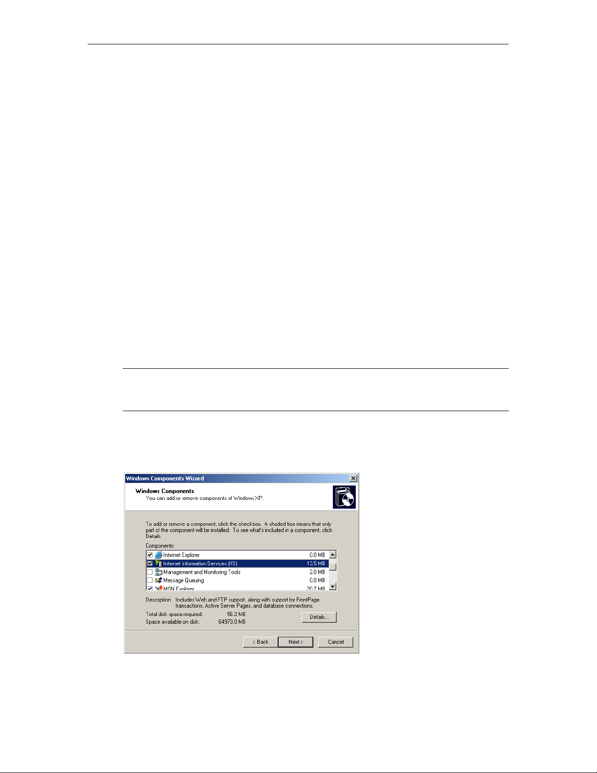
In order to host the set top box files on a PC, it must be configured as a web server. Use the
following steps to configure a PC as a web server or to verify that it's configured properly.
Note The following steps show how to configure a PC running Windows Server 2003 or
Windows XP. If your PC has Windows Server 2008 or Windows 7 the steps will be
similar but slightly different.
To configure your PC as a web server:
1. Go to
2. Select
Start > Control Panel > Add or Remove Programs.
Add/Remove Windows Components in the left navigation pane.
3. Check
Multi-Format STB Quick Start 23
Internet Information Services (IIS) and then Details.
Page 30
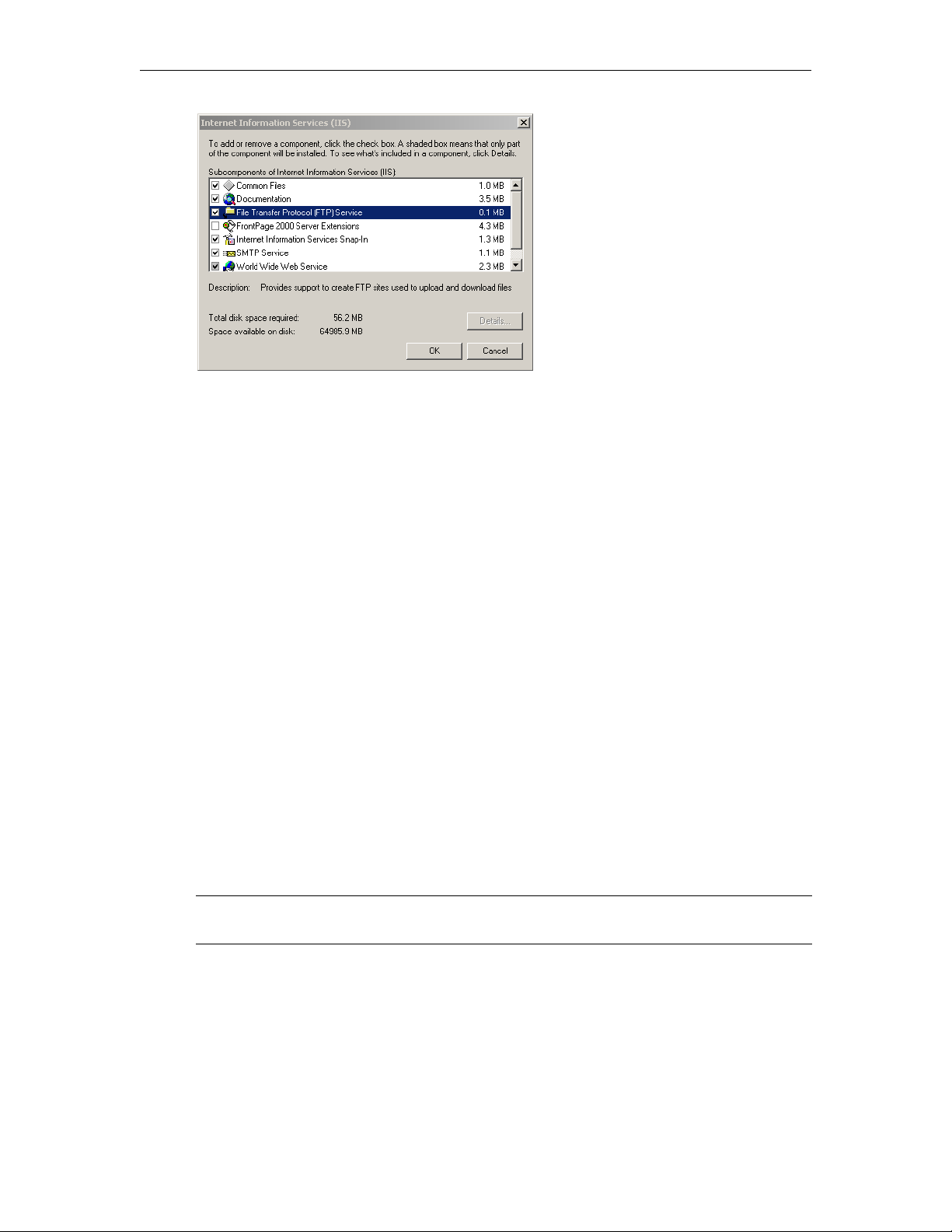
4. Check File Transfer Protocol (FTP) Service and World Wide Web Service, then OK, Next,
Finish. (Initially when the FTP service is added, the user name and password is
and
anonymous.)
Putting the Files on a PC
To put the STB files on a PC:
1. Telnet to the set top box as explained below and
Home Directory. By default, the home directory for the Default Web Site is
IIS
c:\inetpub\wwwroot. For syntax information type ftpput and press Enter.
2. Login with
userid = iptv, password = settopbox
3. On the set top box, type:
a. cd titanium/demo_page/kumat/vbrick
b. ftpput <FTPServer_IP_address> –u <pc_ftp_username> –p <pc_ftp_password>
channels.xml channels.xml
c. Repeat this
ftpput for all files in titanium/demo_page/kumat/vbrick
4. During transfer the file will be automatically copied to
5. After transfer, manually copy all of the files from
6. After you have configured the set top boxes to point to the PC as explained in the next
section, reboot the set top box(es) and you are done.
7. If you subsequently need to change the channels file, you simply modify or replace the
c:\inetpub\wwwroot and reboot the set top box(es).
file in
ftpput the required files into your PC's
c:\inetpub\ftproot.
ftproot to c:\inetpub\wwwroot.
Configuring the STB Home Page
Caution Perform this step carefully. If you enter an invalid URL you will be unable to
communicate with any of the set top boxes in your network.
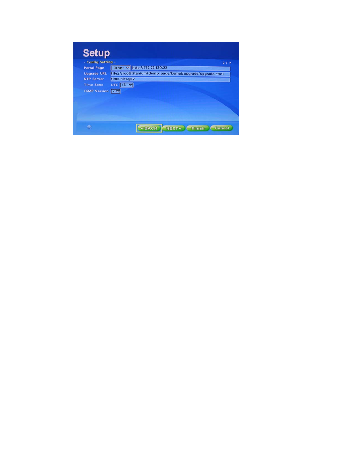
To configure the STB Home Page to point to a PC:
1. On the STB, navigate to the
2. Go to
Portal Page > Other and enter the IP address of a Windows PC.
3. When done, enter a password and click
4. Then repeat for each set top box.
24 © 2016 VBrick Systems, Inc.
Config Setting page in the Setup program.
Save Changes.
Page 31
Using Multiple channel.xml Files
You can create multiple channel.xml files which can allow you to switch your local channel
listing remotely. For example, a central control system may want to push a particular channel
to one or more set top boxes, to send an announcement or tune device to a particular event.
In the example below, we will set up a default channel file and three alternate channel files.
Creating a Channel Guide
Configuring Multiple Channel Files
You will create multiple channel.xml files and store them on the set top box in the /data
folder, where the original channels.xml file is stored. You need a
the default, power-up channel listing. Then you will create three additional channel files, for
example:
channel1.xml, channel2.xml and channel3.xml. Your default channel file could look
like the one in the users’ manual or any other setup of your choice:
Default Channel
This channel file starts up in channel listing mode and sets up a power-on default channel to
play:
<?xml version="1.0" encoding="utf-8"?>
<STBLocalUI>
<!-- this is general information -->
<Title>VBrick Systems, Inc.</Title>
<GlobalMsg>Test enviroment.</GlobalMsg>
<FullScreen>0</FullScreen>
<!-- Multicast stream -->
<Stream>
<ProgramName>OPS H.264 SDP</ProgramName>
<Message>Operations H.264 Multicast Brick SDP</Message>
<URL>http://172.17.2.17/vbStream1T1.sdp</URL>
</Stream>
<!-- RTSP -->
<Stream>
<ProgramName>OPS H.264 RTSP</ProgramName>
<Message>Operations H.264 SD RTSP</Message>
<URL>rtsp://172.17.2.17/vbStream1S1</URL>
</Stream>
channel.xml file to provide
<!-- Windows Media -->
<Stream>
<ProgramName>OPS WM</ProgramName>
<Message>Operations WM http</Message>
<URL>http://172.17.120.111:8080/vbrickvideo1</URL>
Multi-Format STB Quick Start 25
Page 32

<DfltStrm>x<DfltStrm>
</Stream>
</STBLocalUI>
Channel 1
The first channel file will play a live video telecast from a VBrick encoder. It will start up in
full screen mode. The file is rather simple since there is only one channel.
<?xml version="1.0" encoding="utf-8"?>
<STBLocalUI>
<!-- this is general information -->
<Title>News Update from Company </Title>
<GlobalMsg>News special broadcast</GlobalMsg>
<FullScreen>1</FullScreen>
<!—h.264 Typical multicast stream from VBrick encoder, in RTP mode -->
<Stream>
<ProgramName>News Channel x , Company y</ProgramName>
<Message>What you want to say in the full screen top banner</Message>
<URL>http://172.17.2.17/vbStream1T1.sdp</URL>
</Stream>
</STBLocalUI>
Channel 2
The second channel is more or less the same. The source could be from a different VBrick
encoder. In this example we will use an Mpeg2 encoder which is sending multicast
<?xml version="1.0" encoding="utf-8"?>
<STBLocalUI>
<!-- this is general information -->
<Title>Video presentation from Company </Title>
<GlobalMsg>regular telecast</GlobalMsg>
<FullScreen>1</FullScreen>
<!—Mpeg2 multicast stream from VBrick encoder, Transport Stream mode IP
239.33.14.77 UDP port 4444-->
<Stream>
<ProgramName>Morning announcements , Company name</ProgramName>
<Message>Morning announcement</Message>
<URL>tv://239.33.14.77:4444</URL>
</Stream>
</STBLocalUI>
Channel 3
The third case is more or less the same again. This time we will play a stored file from the
VOD-W server
<?xml version="1.0" encoding="utf-8"?>
<STBLocalUI>
<!-- this is general information -->
<Title>Training video, Company x</Title>
<GlobalMsg>recorded training material</GlobalMsg>
<FullScreen>1</FullScreen>
<!—Play recorded content from the VBrick VOD-W server-->
<Stream>
<ProgramName>HR Training session 1 , Company name</ProgramName>
<Message>Training video, HR session 1</Message>
<URL>rtsp://VOD-Server hostname or IP/ContentResourceName.mpg</URL>
</Stream>
</STBLocalUI>
26 © 2016 VBrick Systems, Inc.
Page 33

Creating a Channel Guide
Testing the Configuration
Once these files have been created and stored on the STB, and the encoder's / VOD content
is available, testing can be done.
To test the system:
1. Log into the STB using Telnet.
2. At the # prompt, type the following:
# gotourl file:///root/titanium/demo_page/kumat/vbrick/
home.htm?CXML=channel3.xml
This will load the new channel file. So in the above example, channel3.xml will go to the
third channel file (training recorded video) as shown above. Repeat this step to test
channel1.xml and channel2.xml.
3. To go back to the default channel file which loads at power-up type:
#gotourl file:///root/titanium/demo_page/kumat/vbrick/home.htm
Multi-Format STB Quick Start 27
Page 34

Managing the Set Top Box
Topics in this chapter
Overview . . . . . . . . . . . . . . . . . . . . . . . . . . . . . . . . . . . . . . . . . . . . . . . . . . . . . . . . . . . . . . . . 29
Overview
Table 10 shows the tools you can use to manage the set top box. Each tool is best suited for
specific tasks. For example, use the Setup program to configure DHCP settings or Telnet for
an upgrade.
Table 10. Management Tools
Tool Use to ... User Name | Password
Telnet Upgrade STB firmware. iptv | settopbox
Web Interface Change Telnet password. iptv | settopbox
Setup Set DHCP and Video & Audio Output Setting. 1234
Chapter 4
Reset factory defaults, change password. 5678
VBDirectory Check IP address or software version. n/a
Telnet
To get the channels.xml file or the config.txt file you will need to use Telnet, SSH, or a
similar tool. Telnet is particularly important if you are unable to access the device through
other means. For example the box can lock up, freeze, or hang if you enter erroneous or
incompatible setup parameters. If this happens, Telnet may be the only way to recover. To
change the Telnet password see
Web Interface on page 31.
Multi-Format STB Quick Start 29
Page 35
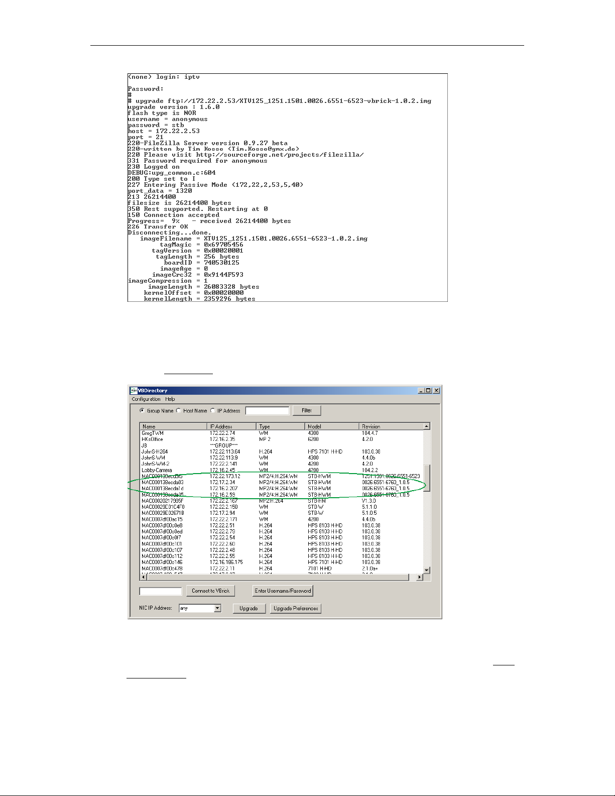
VBDirectory
VBDirectory shows all networked VBrick devices at your site. Multi-Format STBs are
identified in the
Support
Downloads site.
Model column as STB-HWM. You can install VBDirectory from the VBrick
Setup
The Setup program is the recommended method for configuring the set top box. See STB
Configuration on page 10 for complete details.
30 © 2016 VBrick Systems, Inc.
Page 36
Managing the Set Top Box
Web Interface
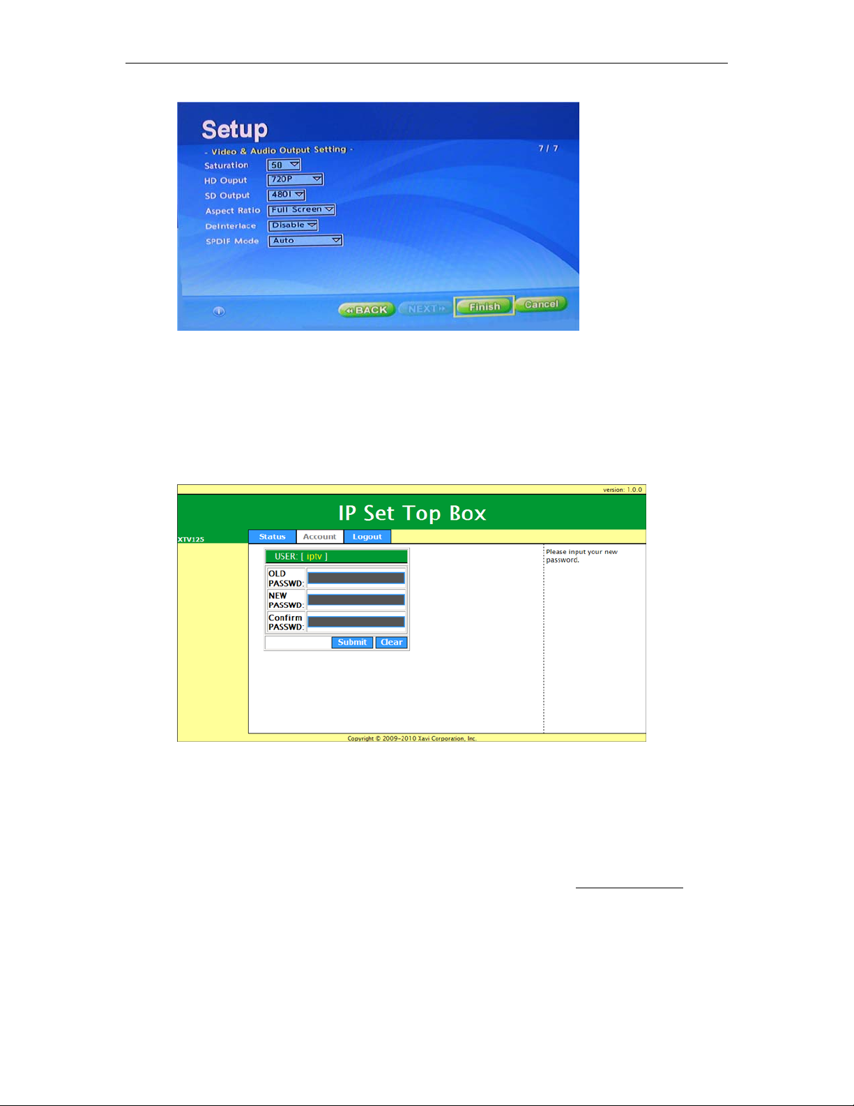
You typically use the Web Interface to change the Telnet password. To display this interface,
open a browser and enter the IP address of the set top box. After logging in, click on the
Account tab to change the Telnet password; click on the Status tab to display the IP Address,
Firmware Version, and other data. To launch the Web Interface, open a browser and enter the
IP address of the set top box.
Disabling the Web Interface
In some cases you may wish to disable access to the Web Interface so that external browsers
cannot connect to the internal web server. Normally the page associated with this web server
allows you to view certain STB information and also allows you to set the Telnet password.
For internet security reasons, you may not want this page to appear or the port to be opened.
This can be accomplished by editing the
stb.webserver.enable: 1 in the Web Service Setting section (see Editing Config.txt on
page 49). Simply change the 1 to a 0 and save the file back to the STB. Now nothing will be
returned when a user attempts to browse to the set top box using http.
# Set 0 to disable stb web server
stb.webserver.enable: 1
Multi-Format STB Quick Start 31
config.txt file. Open the file and search for
Page 37

Setting the Password via Telnet
If you have disabled the Web Interface as explained above, you can still change the Telnet
password using Telnet.
To set the Web Interface password using Telnet:
1. Telnet to the STB, and login. Wait for the # prompt and type in the following command
and Enter:
2. The unit will respond with the following:
Changing password for iptv. Enter the new password (minimum of 5, maximum of 8
characters). Please use a combination of upper and lower case letters and
numbers. Enter new password:
3. Enter a new password of your choice, obeying the min/max character rules as explained.
Press Enter and retype to confirm.
4. Once you logoff Telnet you will subsequently need to enter the new password. Be sure to
save the new password in an accessible location. Lost passwords cannot be recovered and
will require factory intervention.
passwd iptv
32 © 2016 VBrick Systems, Inc.
Page 38

Software Upgrade
Topics in this chapter
Overview . . . . . . . . . . . . . . . . . . . . . . . . . . . . . . . . . . . . . . . . . . . . . . . . . . . . . . . . . . . . . . . . 33
Using the Setup Program . . . . . . . . . . . . . . . . . . . . . . . . . . . . . . . . . . . . . . . . . . . . . . . . . . . . 33
Using Telnet. . . . . . . . . . . . . . . . . . . . . . . . . . . . . . . . . . . . . . . . . . . . . . . . . . . . . . . . . . . . . . 34
Using an IIS Server . . . . . . . . . . . . . . . . . . . . . . . . . . . . . . . . . . . . . . . . . . . . . . . . . . . . . . . . 35
Mass Upgrade Using a VEMS Server . . . . . . . . . . . . . . . . . . . . . . . . . . . . . . . . . . . . . . . . . . 36
Overview
From time to time VBrick may make new STB software available. This topic explains how to
upgrade the STB software when a new image is available. As explained below, there are
multiple ways to upgrade the set top box. You can use the Setup pages; you can use Telnet;
you can host the files on a local PC that has an IIS server; or use an use the mass upgrade
feature on the VEMS server.
meet the requirements at your site.
The method you use depends on which scenario it most likely to
Chapter 5
If you have Gold Plus technical support, or you purchased your STB from VBrick within the
last 90 days, you are entitled to receive Multi-Format STB v2.0.1 firmware free of charge. If
you do not qualify with either of these options you can update/renew your support contract
to become eligible to use this firmware. Contact VBrick Support Services to obtain the
upgrade image password.
Using the Setup Program
Note You can connect to the upgrade utility page via HTTPS in order to perform an
upgrade. You cannot connect directly to the upgrade image via HTTPS.
To upgrade using the Setup program, press the Help key during a reboot and login with the
default password
FTP, HTTP, or HTTPS as in the following example. This example assumes that the
<server_ip_address> is that of an anonymous FTP server that has the .img file of the new
software release you want to load on the STB (see Step 4 on page 35).
Format:
Example: ftp://172.22.2.53/XTV125_1251.1501.0026.6551-6523-vbrick-1.0.2.img
5678. In the Upgrade Image field, enter the path to upgrade image using
ftp://<server_ip_address>/<upgrade_image_filename>
Multi-Format STB Quick Start 33
Page 39
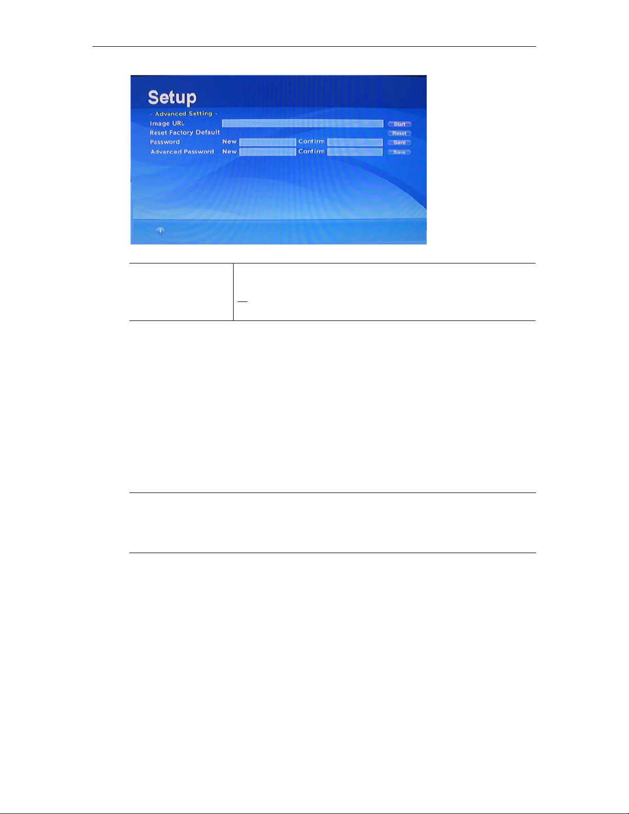
Reset Factory Default Use this option after a software upgrade is complete to return a
Using Telnet
To upgrade box using Telnet, open a Telnet session with login name = iptv and password =
settopbox. Then enter Telnet commands as shown in the examples below. The format of the
upgrade command is shown below. For syntax information type upgrade and press Enter.
unit to its original factory condition. If you do this, be sure to note
all existing settings. Also backup any information in the root/data
folder, especially
config.txt and channels.xml.
Format:
Example:
upgrade ftp://<server_ip_address>/<upgrade_image_filename> <upgrade command
line option>
upgrade ftp://172.22.2.53/XTV125_1251.1501.0026.6551-6523-vbrick-1.0.2.img 3
Telnet Examples
Notes • Be sure to backup your files including config.txt, channels.xml, adjust.xml and
any files you may have stored in
• Note that if you fail to include the command line option (see below) the unit will
replace the
# rm /root/data/rc.d/rc80.user
# upgrade ftp://172.16.1.244/XTV125_1251.1501.0026.6551-6760_1.0.5.img 3
config.txt file and not reboot when done.
If you wish to set the unit to the factory defaults, use the following command (instead of
previous command) with care:
# rm /root/data/* -rf
Upgrade Command Line Options
# upgrade ftp://<ipaddress>/filename.img 1
This will replace the config.txt file with the new version. Note that any configuration
changes will be lost with this option.
/root/data (such as alternate channel.xml files.
# upgrade ftp://<ipadd8ress>/Filename.img 3
This will keep the old config.txt file.
34 © 2016 VBrick Systems, Inc.
Page 40

Using an IIS Server
You can also upgrade your set top boxes by using an IIS web server (to host the upgrade
files) and an FTP server (to serve those files). You can use a VEMS server (if present) or you
can use a PC configured with IIS (see
web server can host a set of pages (located in
download) that are used during the STB's initial boot process. The actual upgrade code image
is available separately from VBrick
Software Upgrade
Configuring a PC as a Web Server on page 23). The
UPG.zip as part of the MF-STB software
Support Services.
The STB has a configuration parameter (see
which specifies the upgrade
Image URL. This URL is a link to a page, hosted on your web
Upgrade, Reset, Change Password on page 16)
server. When you configure the STBs to point to that page, they will be automatically
upgraded after a reboot if the image file is newer. The steps are basically the same if you are using
a VEMS server or a PC configured as a web server.
To use a web server (and an FTP server) to upgrade STBs:
1. Go to the web server and unzip the files in
2. Go to the STB and edit the
can use Telnet and vi to do this (see
config.txt file to point to the web server used in Step 1. You
Editing Config.txt on page 49 for more details); you
can also use the remote control to edit the
a. Open a Telnet session and edit
b. Go to the
Page Setting section and modify the following line to point to the web
config.txt.
UPG.zip into the wwwroot folder.
Upgrade URL on the Config Setting page.
server used in Step 1:
stb.url.fwupg: http://<web_server_ip_address>/upg/upgrade/upgrade.html
3. Repeat Step 2 for each STB.
4. Go to the FTP server, set up an anonymous FTP account and subfolder, and copy the
upgrade .img file to the subfolder in
ftproot. (Optionally you can use the same IIS server
and serve the file using HTTP: see Step 5.)
5. Go to the web server and edit the following line in
upgrade_path.xml to point to the FTP server name and folder location. (This example
wwwroot/UPG/upgrade/
assumes an anonymous FTP server with the anonymous home account containing the
.img file). Optionally you can perform an HTTP transfer by uncommenting the
corresponding xml line and modifying the location and file name.
<upgPath>ftp://anonymous@<ftp_server_ip_address>/<image_file_name.img</upgPath>
<!—OR Use HTTP as option
<upgPath>http://<ftp_server_ip_address>/<image_file_name.img</upgPath>-->
6. This completes the initial configuration. Now you can now test the setup to verify the
upgrade is configured properly using the following steps:
a. Verify the FTP server is working properly and reboot the STB.
b. If you do not have a new version of software to test with, simply rename the file (i.e.
increment the last digit) and edit the
version. For example if
xxxx_1.0.7.img making sure you (1) edit the file name and (2) put the image file in
xxxxx_1.0.6.img is the current version, rename it to
upgrade_path.xml file name to be the next
the appropriate folder.
c. Reboot the STB. Since you only renamed the file (and did not change the actual
version embedded in the code), the STB will prompt you for an upgrade every time it
boots up. This will not happen once you place a newer version in
Multi-Format STB Quick Start 35
ftproot.
Page 41
d. After the reboot you are prompted to Cancel or Upgrade. Click Upgrade to run the
upgrade even though you are replacing the image file with the same version (only the
filename has changed).
e. When done, rename the file back to its original name and edit the
to the same name. Now when you reboot the STB, you will not be prompted with
the upgrade page.
Mass Upgrade Using a VEMS Server
If you will be upgrading multiple set top boxes, VEMS Mystro (6.2.1 or higher) has a mass
upgrade feature that will simplify this process. This topic explains how to upgrade multiple
set top boxes at the same time using built-in functionality on the VEMS server. This
built-functionality uses a configuration parameter that defines the
When the STB boots up, it branches to this page to check whether the STB needs to update
its firmware. This decision is based on a value in a configurable xml file hosted on the
upgrade server. If an upgrade is required (determined by comparing the current version of
the STB with the xml file on the upgrade server page), you will have the option to upgrade or
not upgrade. After five minutes the upgrade will automatically begin (thus allowing for
unattended upgrades).
upgrade_path.xml
Upgrade Server Page URL.
Notes •
The upgrade image is password-protected. Before performing an upgrade you will
need to contact VBrick
Support Services for the password.
• The steps explained here assume that you have added the set top boxes to the
VEMS configuration and created a unique user for each one (see
STB and Auto-
Discover STB respectively in the Portal Server Admin Guide).
• The following procedure explains how to upgrade STBs using the VEMS
Scheduler. If you do not have a Scheduler license you will need to set the Portal
Server URL manually following the steps in Multi-Format STB Quick Start Guide.
1. Unlock the Upgrade Image
If you will be using the VEMS server to upgrade multiple STBs, you can find the
password-protected upgrade image on the VEMS server after the VEMS (6.2.1 or higher)
software is installed.
Services for the password.
To unlock the image:
1. Navigate to folder containing the upgrade image. The folder path (see below) is slightly
different depending on whether the VEMS server is running on a 32 or 64-bit machine.
Server Path to Upgrade Image
32-bit
64-bit
C:\Program
Files\VBrick\Maduro\STB\MFSTB_Upgrade\XTV125D_1255.1501.0026.8066_2.0.1.zip
C:\Program Files
(x86)\VBrick\Maduro\STB\MFSTB_Upgrade\XTV125D_1255.1501.0026.8066_2.0.1.zip
Before unzipping the file you will need to contact VBrick Support
2. Right-click on the zip file and select
Extract Here. When prompted, enter the 12-digit
password (with no spaces or other characters) you received from VBrick Support
Services.
Make sure you unzip the file into the specified folder. If you change the folder
the upgrade will fail.
36 © 2016 VBrick Systems, Inc.
Page 42
Software Upgrade
2. Configure the Global Setting
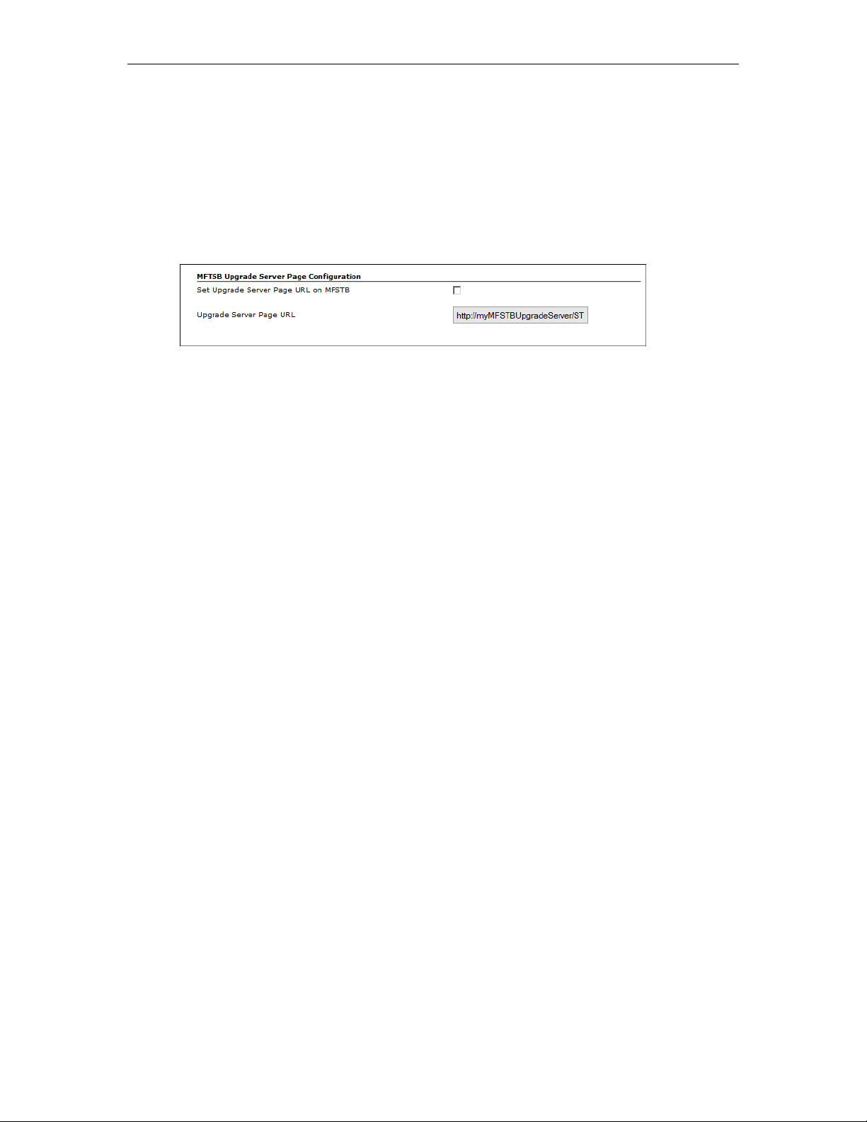
The next step is to enable the Set Upgrade Server Page functionality (which is disabled by
default). To enable the this feature go to
server and check the
URL (as explained below) defines the path to the default upgrade server. If you ever need to
replace the
http://myMFSTBUpgradeServer/STB/MFSTB_Upgrade/UPG/upgrade/upgrade.html
Upgrade Server Page URL the default is:
Set Upgrade Server Page URL on MFSTB box. The Upgrade Server Page
System Settings > Global Settings on the Mystro
3. Configure the Upgrade Server URL in VEMS
After enabling the upgrade server functionality, you will need to configure the upgrade server
URL. There are two ways to proceed: you can (1) configure a DNS entry to point to your
VEMS server (using
URL and path.
myMFSTBUpgradeServer) or you (2) can manually set the upgrade server
Configuring a DNS Entry
The VEMS Mystro 6.x software includes an STB upgrade server configured for use in an
environment where there is a DNS entry (
Mystro server. If you configure a DNS entry for
myMFSTBUpgradeServer) that points to the VEMS
myMFSTBUpgradeServer that points to your
VEMS server you can go to Step 2a below and set the file name.
Configure the Upgrade Server URL and Path
If you don't have a DNS server (or don't make a DNS entry for myMFSTBUpgradeServer) you
will have to modify the STB configuration in two different places:
1. You will need to modify the
Global Settings page to point to the VEMS server URL. For example:
http://myMFSTBUpgradeServer/STB/MFSTB_Upgrade/UPG/upgrade/upgrade.html
2. You will also need to edit the
value in the
<upgPath> tag points to the STB image file installed on the VEMS server. On
a 64-bit server, the file path is:
(x86)\VBrick\Maduro\STB\MFSTB_Upgrade\UPG\upgrade\upgrade_path.xml
a. Right-click on
upgrade_path.xml, select Open with Notepad, and note the following
code:
<!-- The HTTP transfer option is used here, the ftp is commented out -->
<upgPath>http://myMFSTBUpgradeServer/STB/MFSTB_Upgrade/
XTV125_1251.1501.0020.6553_1.0.7.img</upgPath>
b. Replace
myMFSTBUpgradeServer with the IP address or DNS host name of the VEMS
server.
c. Replace
XTV125D_1255.1501.0026.8066_2.0.1.img (or the latest MF STB name/version).
XTV125_1251.1501.0020.6553_1.0.7.img with
Upgrade Server Page URL parameter (shown in bold) on the
upgrade_path.xml file on the VEMS server so that the
C:\Program Files
Multi-Format STB Quick Start 37
Page 43
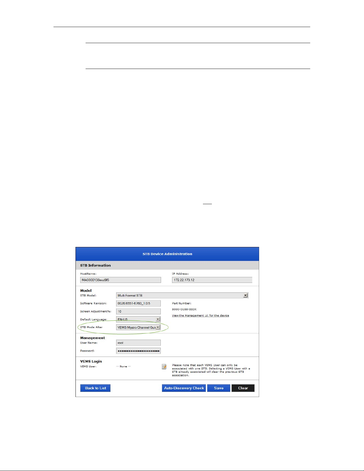
Note
XTV125D_1255.1501.0026.8066_2.0.1.img is the latest STB code image. To
perform future upgrades you will need to replace this file and modify
upgrade_path.xml
4. Configure the STB with the VEMS Upgrade Server URL
Each STB has a configuration setting which stores the location of Upgrade URL and the STB
needs to know where the upgrade server pages are located. This setting can be configured
manually using the STB setup pages, or automatically using one of the methods outlined
below.
STB in VEMS Mode
If the STB is already in VEMS mode and you want to add automatic upgrade capability you
are almost done. In this scenario the STB, upon reboot, will reconnect to VEMS. The Global
Settings in VEMS will determine if the automatic upgrade feature is enabled, and if so, will
automatically configure the STB's Upgrade URL using the
you entered in the previous step.
STB in Local Mode
If you have a new STB, or one which has not been configured for VEMS mode, you can use
the following steps to set the STB to VEMS mode
VEMS Scheduler feature. As explained below, the easiest way to accomplish this is to create a
schedule in VEMS that will automatically reset the upgrade URL when the STB reboots.
and configure the Upgrade URL using the
Upgrade Server Page URL entry
To configure the VEMS Upgrade URL:
1. Launch the VEMS admin interface and go to
Devices > STB.
2. For each set top box, set the
Guide.
38 © 2016 VBrick Systems, Inc.
STB Mode after Schedule parameter to VEMS Mystro Channel
Page 44
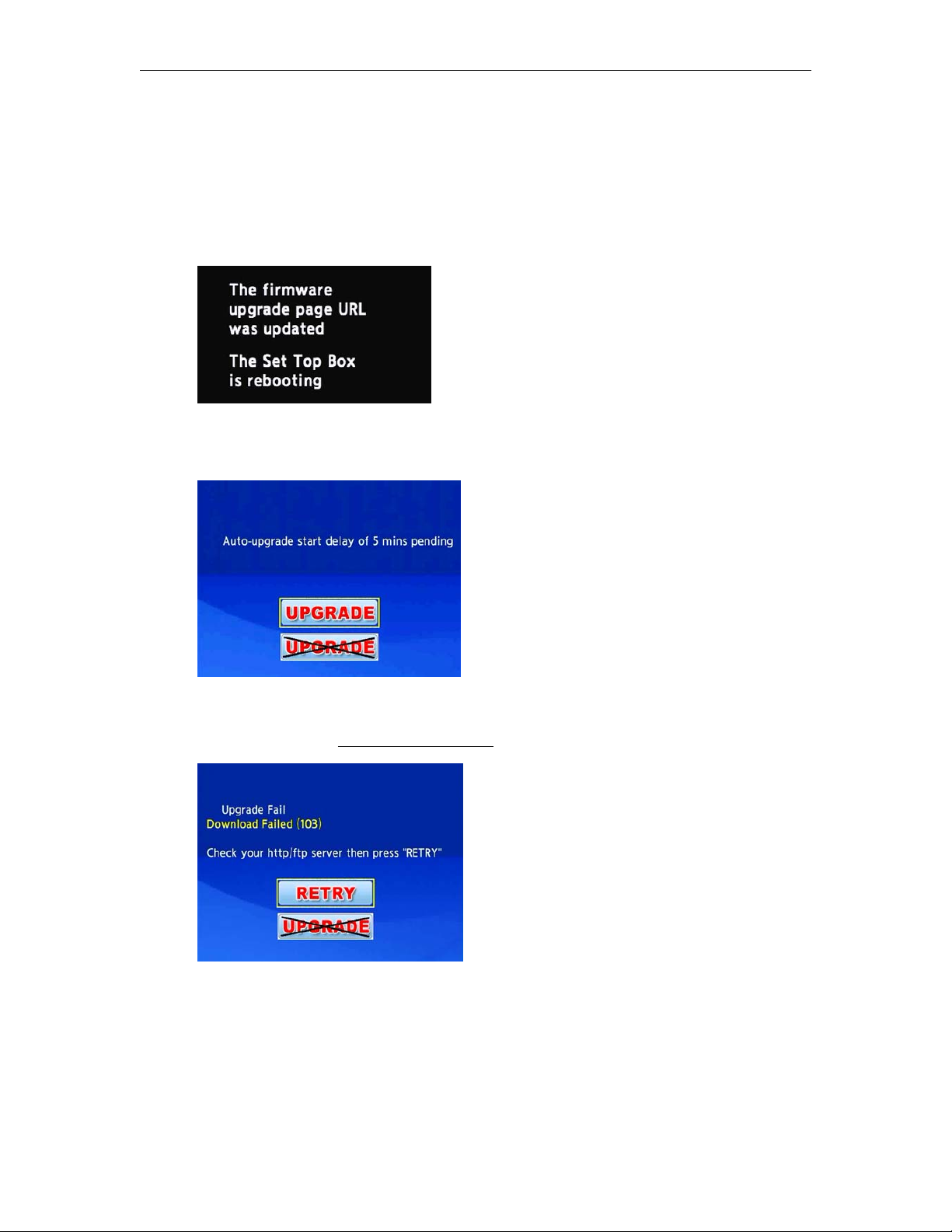
Software Upgrade
3. Open the VEMS Mystro client interface and create a schedule, for example a Rebroadcast
Content.
4. Set the schedule for
devices, be sure to select all of the STBs you will be upgrading.
5. After the schedule runs the VEMS
If the current
Now with a Duration of 1 minute. When selecting destination output
Upgrade Server Page URL will be written to each STB.
Upgrade Server Page URL value has changed, you will see the following
message. This is normal behavior and no user action is required.
6. After the reboot, if a firmware upgrade is required, you can choose to run the upgrade or
not run the upgrade. If you run the upgrade, the STB will reboot, load new firmware, and
you are done. If you do nothing, the upgrade will automatically begin after five minutes.
If a STB needs to upgrade but the firmware image file is not on the server, the failure page
below is displayed. This page will display every time the STB logs into VEMS, including after
a schedule runs. (See
Cancelling the Upgrade below to disable this functionality.)
Cancelling the Upgrade
If you choose to cancel an upgrade by clicking on one of the images above, the cancellation is
only temporary and you will see the same image prompt every time the STB reboots. If you
have trouble upgrading or do not want the STB checking for an upgrade at startup, you can
cancel upgrade checking permanently.
Multi-Format STB Quick Start 39
Page 45

To cancel upgrade checking:
1. Make sure the
2. Delete the string in
Set Upgrade Server Page URL on MFSTB is checked in Global Settings.
Upgrade Server Page URL and leave the field blank.
3. Reboot the STB. This can only be done by power cycling the unit or using Telnet.
4. When the STB reboots, it will no longer attempt to contact the upgrade server.
40 © 2016 VBrick Systems, Inc.
Page 46
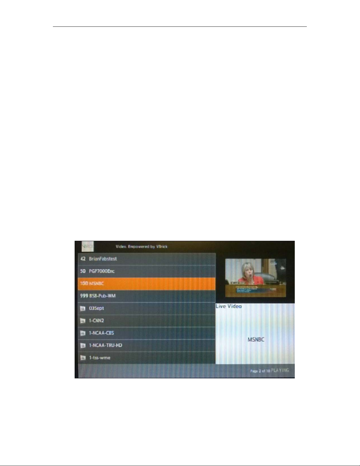
Using the Remote Control
Topics in this chapter
Overview . . . . . . . . . . . . . . . . . . . . . . . . . . . . . . . . . . . . . . . . . . . . . . . . . . . . . . . . . . . . . . . . 41
Using the Remote Control (VEMS 5.x) . . . . . . . . . . . . . . . . . . . . . . . . . . . . . . . . . . . . . . . . . 42
Using the Remote Control (VEMS 6.x) . . . . . . . . . . . . . . . . . . . . . . . . . . . . . . . . . . . . . . . . . 44
Using the Remote Control to Change the Channel . . . . . . . . . . . . . . . . . . . . . . . . . . . . . . . .46
Overview
The IR Remote Control is a handheld "infrared" device you can use to control live and stored
streams running on the Multi-Format set top box. You can select and play streams by
pointing the unit at the infrared sensor on the front in the lower-right corner. Only those
buttons described on the following pages are active. Do not press any other buttons on the remote.
Note that the Remote Control buttons behave differently depending on whether you are
in Local Mode or Portal Server Mode. (If your screen has a Menu option as shown in
Figure 10, you are in Portal Server Mode 6.x.) Be aware that the Multi-Format set top box
does not enforce copyright restrictions on stored content.
Chapter 6
Figure 10. Portal Server Mode (VEMS 6.x)
Multi-Format STB Quick Start 41
Page 47

Using the Remote Control (VEMS 5.x)
Portal Server Mode
Button Function
Info Portal Server mode only. Displays information about the
currently selected stream. Press Back when done.
Red Use to power the device on/off. Same as reset.
Mute Mute/unmute volume. Use the volume controls on the
display device to set volume.
0–9 Portal Server mode. Enter a PIN, or enter a search string
using the number keypad for text entry.
Enter Press when input complete.
Clear Deletes the previous digit or character when entering search
parameters or a PIN.
Page Move to top, bottom, next, or previous page.
Menu Toggle the Menu on or off.
Back Return to previous screen.
Vol Adjust the audio up or down.
CH Advance channel up or down.
OK Select and play the highlighted channel. Initiate an action or
select an option depending on cursor focus.
Arrows Change focus to next item; select previous stream.
Prev Go to previous page.
Next Go to next page.
RW VOD content only: Rewind the current stream.
Play/Pause Play/Pause the selected stream
FF VOD content only: fast forward the current stream
Help Press repeatedly during power-up to display setup pages.
Full Screen Go to fullscreen; exit fullscreen.
Rec Record stream. During recording, a red indicator is shown in lower right area of
window.
Stop Stop a recording in progress.
Search Display the search window. Press Search again to exit window.
Live Go to Live Video page.
VOD Go to Stored Video page.
Sched Display scheduled streams available for viewing.
Mark VOD content only: Create a bookmark.
42 © 2016 VBrick Systems, Inc.
Page 48

Local Mode
Button Function
Info Portal Server mode only.
Red Use to power the device on/off. Same as reset.
Mute Mute/unmute volume. Use the volume controls on the
display device to set volume.
0–9 Portal Server mode. Enter a PIN, or enter a search string
using the number keypad for text entry.
Enter Press when input complete.
Clear Deletes the previous digit or character when entering search
parameters or a PIN.
Page Move to top, bottom, next, or previous page.
Menu Portal Server mode only.
Back Return to previous screen.
Vol Adjust the audio up or down.
Using the Remote Control
CH Advance channel up or down.
OK Select and play the highlighted channel. Initiate an action or
select an option depending on cursor focus.
Arrows Change focus to next item; select previous stream.
Prev Go to previous page.
Next Go to next page.
RW VOD content only: Rewind the current stream.
Play/Pause Play/Pause the selected stream
FF VOD content only: fast forward the current stream
Help Press repeatedly during power-up to display setup pages.
Full Screen Go to fullscreen; exit fullscreen.
Rec Portal Server mode only.
Stop Portal Server mode only.
Search Portal Server mode only.
Live Portal Server mode only.
VOD Portal Server mode only.
Sched Portal Server mode only.
Mark Portal Server mode only.
Multi-Format STB Quick Start 43
Page 49
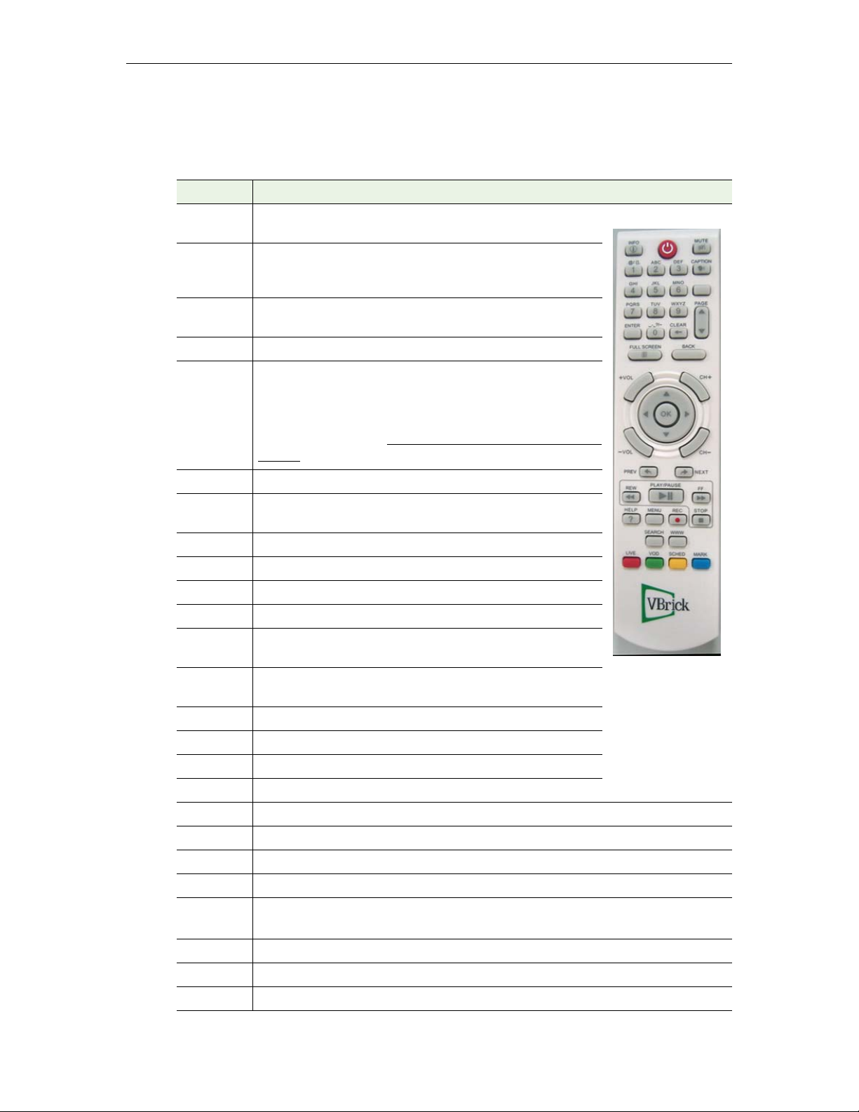
Using the Remote Control (VEMS 6.x)
Portal Server Mode
Button Function
Info Portal Server mode only. Displays information about the currently
selected stream. Press Info to again to exit.
Red Press once to put the unit in standby (the screen will be blank but
the unit can still be scheduled to play streams). Press a second time
to reboot the unit.
Mute Mute/unmute volume. Use the volume controls on the display
device to set volume.
Caption Show or hide closed captions. Not supported on all TVs.
0–9 Portal Server mode. Enter a PIN, or enter a search string using the
number keypad for text entry.
You may also enter a channel number directly to switch the channel
(live channels only). See:
Channel.
Enter Press when input complete.
Clear Deletes the previous digit or character when entering search
parameters or a PIN.
Using the Remote Control to Change the
Page Move to top, bottom, next, or previous page.
Menu Toggle the Menu on or off.
Back Not active.
Vol Adjust the audio up or down.
CH Advance channel up or down. Works only on Full Screen Live
Video page.
OK Select and play the highlighted channel. Initiate an action or select
an option depending on cursor focus.
Arrows Change focus to next item; select previous stream.
Prev Not active.
Next Not active.
RW VOD content only: Rewind the current stream.
Play/Pause Play/Pause the selected stream
FF VOD content only: fast forward the current stream
Help Press repeatedly during power-up to display setup pages.
Full Screen Go to fullscreen; exit fullscreen.
Rec
Stop If playing an RTSP stream, this button will stop the stream.
Starts or stops a recording. During recording, a red indicator is shown in lower right area
of window.
Search Display the search window. Press Search again to exit window.
Live Go to Live Video page.
44 © 2016 VBrick Systems, Inc.
Page 50

Button Function
VOD Go to Stored Video page.
Sched Not active.
Mark Not active.
Using the Remote Control
Multi-Format STB Quick Start 45
Page 51

Local Mode
Button Function
Info Portal Server mode only.
Red Use to power the device on/off. Same as reset.
Mute Mute/unmute volume. Use the volume controls on the
display device to set volume.
Caption Show or hide closed captions. Not supported on all TVs.
0–9
Enter Press when input complete.
Clear Deletes the previous digit or character when entering search
Page Move to top, bottom, next, or previous page.
Menu Portal Server mode only.
Back Return to previous screen.
Vol Adjust the audio up or down.
CH Advance channel up or down.
OK Select and play the highlighted channel. Initiate an action or
Arrows Change focus to next item; select previous stream.
Prev Go to previous page.
Next Go to next page.
RW VOD content only: Rewind the current stream.
Play/Pause Play/Pause the selected stream
FF VOD content only: fast forward the current stream
Portal Server mode. Enter a PIN, or enter a search string using the
number keypad for text entry.
parameters or a PIN.
select an option depending on cursor focus.
Help Press repeatedly during power-up to display setup pages.
Full Screen Go to fullscreen; exit fullscreen.
Rec Portal Server mode only.
Stop Portal Server mode only.
Search Portal Server mode only.
Live Portal Server mode only.
VOD Portal Server mode only.
Sched Portal Server mode only.
Mark Portal Server mode only.
Using the Remote Control to Change the Channel
With VEMS 6.x, you may also use the remote control to change the channel for live content
46 © 2016 VBrick Systems, Inc.
Page 52
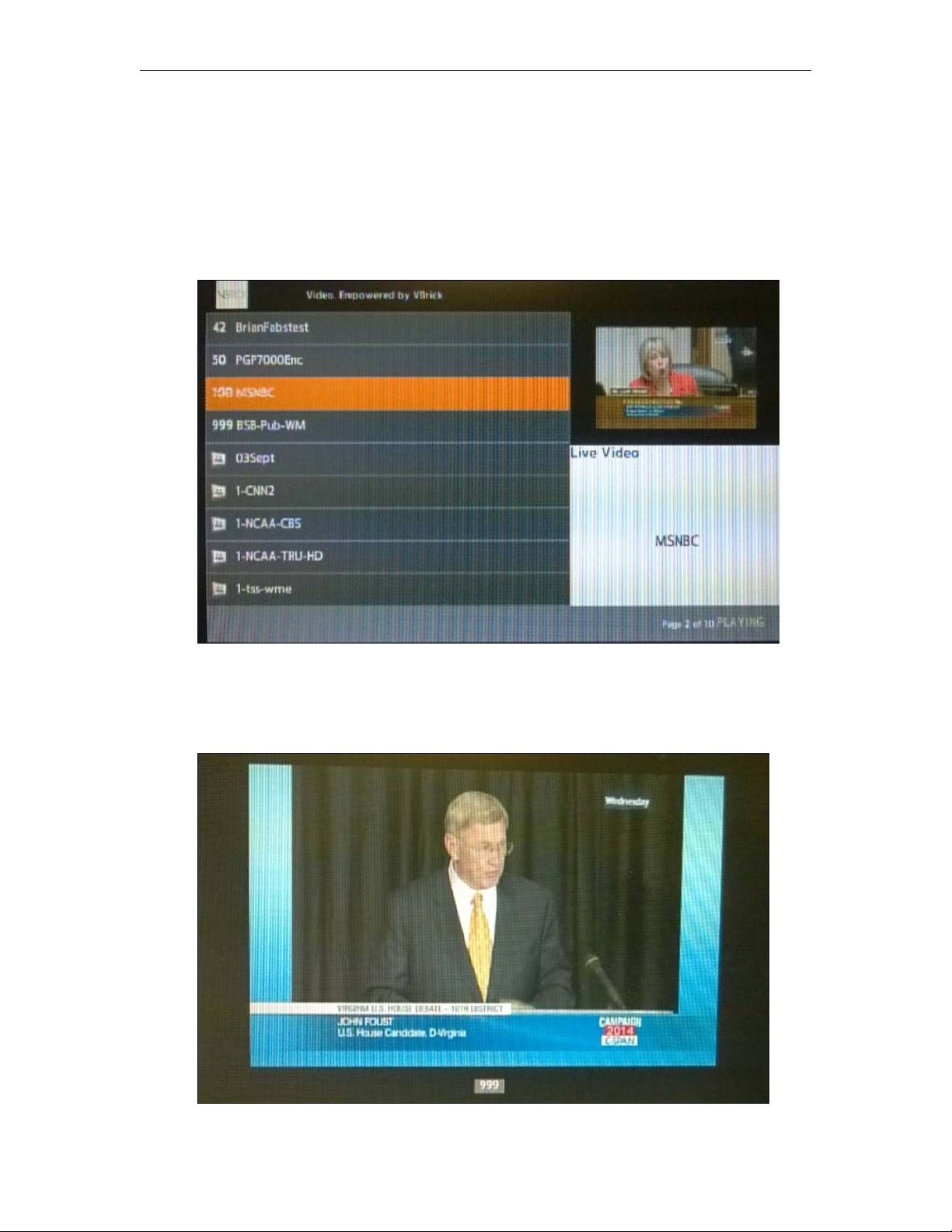
Using the Remote Control
that is associated to a channel. The following is specifically supported:
• Live content
• Server mode (only)
• Guide mode and full screen mode
Live content channels will be listed in the guide by channel number and then in alphabetical
order; the channel number will be displayed instead of the fixed live content icon. This is
seen in the image below.
When a channel on the remote control is pressed, the following may occur:
1. The STB will wait two seconds and then switch to the channel entered. The channel
number is displayed in the lower left portion of the screen or in the center of the screen
if in full screen mode, seen below).
Multi-Format STB Quick Start 47
Page 53

2. If another number is entered during the wait period, the STB will combine the two
numbers and display the new channel number. The wait period restarts.
3. If a non-number key is pressed, the STB assumes the channel switch is canceled.
4. If the channel is not found, a “Channel Not Found” message is displayed in the lower
right portion of the screen (or the center of the screen if in full screen mode) and the
STB does nothing further.
Note When in Search mode, the channel number entered must match the search criteria or a
“Channel Not Found” message will display.
48 © 2016 VBrick Systems, Inc.
Page 54

Editing Config.txt
Topics in this chapter
Overview . . . . . . . . . . . . . . . . . . . . . . . . . . . . . . . . . . . . . . . . . . . . . . . . . . . . . . . . . . . . . . . . 49
Setting Configuration Parameters . . . . . . . . . . . . . . . . . . . . . . . . . . . . . . . . . . . . . . . . . . . . . 49
Overview
If for some reason you cannot directly access the Setup pages, you can use the config.txt file
that resides on the set top box to set various configuration parameters. To do this you will
need to login to the device, via Telnet for example, to get the file. Then make any changes
and put the file back on the STB. Before you can do this you will need to setup an accessible
FTP server. These steps are briefly outlined below.
To modify the config.txt file:
1. Open a Telnet session, login to the STB, and
login: iptv
Password: settopbox
#
# cd data
# ftpput <local_pc_ip_address> -u anonymous -p password config.txt config.txt
2. The config file will typically be copied to C:\Inetpub\ftproot\config.txt (Alternately
you can login and edit the file in place using vi.)
3. Modify the specific parameters as necessary and save the file.
4. When done open a Telnet session, login to the STB, and
machine:
login: iptv
Password: settopbox
#
# cd data
# ftpget <local_pc_ip_address> -u anonymous -p password config.txt config.txt
5. When done reboot the STB to read the file.
Chapter 7
put the file on your FTP server:
get the file from your local
Setting Configuration Parameters
The following table shows the settings in config.txt you will likely need to modify. To avoid
problems, enter your changes carefully and do not change anything else except as directed by
VBrick
Table 11. Notable Configurable Settings in config.txt
Multi-Format STB Quick Start 49
Support Services.
Setting Description
Page Setting • Use to set the Start Mode to VEMS Portal Server IP address.
Display Setting • Use to match display area of output device.
• Use to enable or disable Close Captions.
Page 55

Setting Description
Video/Audio Output
Setting
Use to set Saturation, HD Output, SD Output, Aspect Ratio,
etc.
STB Web Service Setting Used configure VEMS control of the STB.
STB SAP Setting Used for VBrick-specific options.
STB serpassthru Setting Used to set Passthrough options.
Web Service Setting Used to prevent http access to the Web Interface.
Certificate Setting In Portal Server mode you will get a pop-up warning message if
you are using SSL and there is no root certificate available. Set
this parameter to zero (disable validation) to eliminate message.
Remote Controller
Setting
In Portal Server mode, used to dictate specific settings on the
remote control and how they behave when used.
Config.txt File
Config.txt is used to store much of the user configuration. You can edit this file to change a
variety of settings. At the top of the
# This can help you to identify different STB configuration files.
stb.config.version: v2.5.1-vbk
When upgrading between releases, new features are added and new settings will appear in this
file. The version will also change. If you have made changes to the configuration, you will
want to make sure that you have saved those changes. In order to take advantage of the newer
config.txt file, you will want to merge your file into the new one. CAUTION: Performing a
factory default will guarantee that you get the very latest
your changes. You should always have a copy of your
config.txt file you will see a version as shown below:
config.txt file but will overwrite
config.txt saved elsewhere.
#******************************************************************************
#* config.txt -- Configuration file for STB *
#******************************************************************************
#-----------------------------------------------------------------------------#- config.txt version #------------------------------------------------------------------------------
# You may set "config.txt" version here and retrieve it by a JavaScript API.
# This can help you to identify different STB configuration files.
stb.config.version: v2.5.1-vbk
#-----------------------------------------------------------------------------#- Page Setting #------------------------------------------------------------------------------
# Portal page URL
browser.document.default: file:///root/titanium/demo_page/kumat/vbrick/home.htm
# Set VBrick server portal page url
# Note: It is the reference value of portal type in booting setup page.
# If setup this value manually, please modify browser.document.default to the
same URL.
50 © 2016 VBrick Systems, Inc.
Page 56

Editing Config.txt
stb.vbrick.server.url: http://MyVBrickServerHostname_OR_IPaddress
# Upgrade page URL
# Upgrade page with UI for display upgrade progress,information,etc...
# It can use at bootup and schedule upgrade
stb.url.fwupg: http://172.17.1.5/upg/upgrade/upgrade.html
#stb.url.fwupg=file:///root/titanium/demo_page/kumat/upgrade/upgrade.html
# Help page URL
stb.url.help:
#-----------------------------------------------------------------------------#- Language Setting #------------------------------------------------------------------------------
# Set language tag to use if neither the HTTP(S) server, document, or element
# attributes specify one. Language tags are explained in RFC-1766
# en - English
# ja - Japanese
# zh-tw - Chinese Traditional
# ru - Russian
document.language.default: en
# Secondary encoding, the number corresponding to the character encoding to use
# 4 - ISO-Lartin-1
# 17 - Shift-JIS
# 18 - EUC-JP
# 39 - ISO-2022-JP
# 2026 - Big5
# 8 - ISO-Cyrillic
# 2084 - KOI8-R
# 2251 - Windows-1251
document.encoding.user: 4
#-----------------------------------------------------------------------------#- Video/Audio Output Setting #------------------------------------------------------------------------------
# HD/SD output format
# 1080p30, 720p, 720p50, 1080i, 1080i50, 576p, 480p, 576i/pal, 480i/ntsc - HD
# 576i/pal, 480i/ntsc - SD
stb.hd.outputformat: 720p
stb.sd.outputformat: ntsc
# HD/SD saturation from 0 to 100
stb.hd.saturation: 50
stb.sd.saturation: 50
# HD/SD contrast from 0 to 100
stb.hd.contrast: 50
stb.sd.contrast: 50
# HD/SD hue from 0 to 100
stb.hd.hue: 50
stb.sd.hue: 50
Multi-Format STB Quick Start 51
Page 57

# HD/SD brightness from 0 to 100
stb.hd.brightness: 50
stb.sd.brightness: 50
# HD/SD aspect ratio
# 16:9
# 4:3
# Full_screen
stb.hd.ar: Full_screen
stb.sd.ar: Full_screen
# Set to 1 to enable component(D4) output display
stb.component.enable: 1
# Set to 1 to enable HDMI output display
stb.hdmi.enable: 1
# While HDMI is plugged, it will determine whether EDID preferred output format
# is used. When this option is set to "0", it will force output the format you
# set regardless of EDID data.
stb.hdmi.validate_edid_format: 1
# Set HDMI output mode
# pcm
# pass-through
stb.hdmi.audio.output: pass-through
# Set S/PDIF output mode
# auto
# pcm
# pass-through
stb.spdif.output: auto
# Setup the default behavior of the decoder health monitor
# The monitor will check the health of decoder(audio/video) status periodically.
# This setting will determine which source, audio and video, should be monitored.
# auto - decide by audio and video PID. If video PID is existed, monitor video
# stauts. If audio PID is existed, monitor audio status.
# av - force to check both video and audio status periodically.
# a - forece to check audio status periodically.
# v - forece to check video status periodically.
# n - disable health check of decoder, both video and audio.
stb.stm.check_av: auto
# Set to 1 to enable HD and SD deinterlace
stb.stm.deinterlace: 0
# Enable/Disable chromakey color
stb.chromakey.enable: 1
# Set chromakey color
stb.chromakey: #010101
#-----------------------------------------------------------------------------#- Display Setting -
52 © 2016 VBrick Systems, Inc.
Page 58

Editing Config.txt
#------------------------------------------------------------------------------
# Adjust display region
# 1920,1280,720,640 - width
# 1080,720,480,576 - height
stb.ui.width: 1280
stb.ui.height: 720
# The set of pages always displayed in a single redraw ("one-shot rendering")
# rather than progressively as data is retrieved.
# 0 - disable one-shot rendering
# 1 - enable one-shot rendering for URIs where no network access is required.
# 2 - enable one-shot rendering for all URIs.
browser.display.oneshot.mode: 0
# For URIs configured to display using one-shot rendering, the time (centiseconds)
# after which one-shot rendering is cancelled and the page is rendered as data is
# retrieved.
browser.display.oneshot.timeout: 200
# Default background color of browser, format is BGRA
browser.colour.back: dddddd00
# The opacity (0-255) of the highlight shown when an element has focus. The
# highlight colour is determined by the -ant-highlight-color CSS property.
browser.highlight.opacity: 255
# The thickness of the highlight outline. If set to 0, the highlight is not
# drawn as an outline, but instead fills the highlighted element's box.
browser.highlight.thickness: 3
# The minimum space(pixels) between a dialog box and the edge of the viewport.
browser.dbox.margins: 80
# Set to 1 to enable throbber
controller.gif.throbber.enable: 1
# Throbber type from 0 to 3
controller.gif.throbber.index: 0
# The minimum size, in pixels, for a font. Any request for a smaller font size
# uses this size.
font.min_char_size: 14
# Set to 1 to enable Close Caption
stb.closecaption.enable: 1
#-----------------------------------------------------------------------------#- Remote Controller Setting #------------------------------------------------------------------------------
# Set the remote controller device. Ecah one may support different IR protocol
# and/or prefix code.
# 0 - RCU with GI protocol
# 1 - RCU with NEC protocol
Multi-Format STB Quick Start 53
Page 59

# 2 - RCU with Philips RC-5 protocol
stb.remote: 1
# Set power key behavior on the remote control
# 0 - reboot immediately
# 1 - display countdown message on screen and mute AV after 3 secs/unmute AV
# immediately
# 2 - power saving/reboot
# 3 - mute/unmute AV immediately
stb.remote.power: 0
# Set to 1 to turn off front-panel LEDs (power and ether-link) while in standby
# mode
stb.remote.standby.ledoff: 0
# Set the second address code of remote controller. Default 0xffff means don't
# accept second address code
stb.remote.address2: 0xffff
# Set to 1 to enable second power key on remote controller unit
stb.remote.power2.enable: 0
# Set to 1 to enable key repeat
stb.remote.repeat.enable: 1
# Set the threshold for repeat clicking from 400~2000
# Unit: ms
stb.remote.repeat.threshold: 600
# Set the interval for repeat clicking from 400~2000
# Unit: ms
stb.remote.repeat.interval: 400
# Set the response time for tv channel switch from 500~2100
# Unit: ms
stb.switch.channel.response: 700
# Set IR blaster mode
# 0 - Disable IR blaster
# 1 - Enable IR blaster with forwarding IR input
# 2 - Enable IR blaster without forwarding IR input
stb.irblaster.mode: 0
# Set IR blaster forward protocol
# RC5 - forward Philips RC-5/RC-5 Extension protocol
stb.irblaster.forward.protocol:
#-----------------------------------------------------------------------------#- Network Setting #------------------------------------------------------------------------------
# Set to 1 to enable IPv6 DNS query
net.ipv6.enable: 0
#------------------------------------------------------------------------------
54 © 2016 VBrick Systems, Inc.
Page 60

Editing Config.txt
#- UDP meaasge Setting #------------------------------------------------------------------------------
#Set the port number that listening to UDP message
stb.udpmessage.port: 7121
#Set the group IP address that multicasting UDP message
stb.udpmessage.multicast.ip: 225.1.1.1
#-----------------------------------------------------------------------------#- Decode Setting #------------------------------------------------------------------------------
# For transport stream STB need to get stream information from PAT and PMT first,
# thus stream can be decoded correctly. If no PAT data is detected during a time
# interval of PAT timeout set by this, STB will result in failure on decoding
# stream.
# Unit: ms
stb.stm.pattimeout: 600
# For transport stream STB need to get stream information from PAT and PMT first,
# thus stream can be decoded correctly. If no PMT data is detected during a time
# interval of PMT timeout set by this, STB will result in failure on decoding
# stream.
# Unit: ms
stb.stm.pmttimeout: 600
#-----------------------------------------------------------------------------#- Schedule Upgrade Setting #------------------------------------------------------------------------------
# Schedule upgrade quick check URL.
# It's a hidden and simple page that for quick check if upgrade is necessary or
# not. STB connect to this URL when current time is stb.schedule.upgrade.time.
# This page MUST as simple as it can for reduce STB loading and speed check time.
stb.schedule.upgrade.quickcheck.url:
# Schedule upgrade check time
# Schedule upgrade procedure starts when current time is this value.
# The format is hh:mm and 24 hour clock
stb.schedule.upgrade.time:
#-----------------------------------------------------------------------------#- PVR, Time-shift Setting #------------------------------------------------------------------------------
# Set the mount point's path of storage's partion for PVR function.
# Recording file will be saved to stb.pvr.realpath .
# /mnt/usb/usbXX - For usb flash stick, usb hard disk.
# /mnt/hd/hddXX - For SATA hard disk.
stb.pvr.realpath: /mnt/usb/usb11
# Set the windows interval of time-shift mode. Valid from 10(MIN) to 180(MIN)
# For every 10 minutes, the disk usage is around 2.2G Bytes
stb.timeshift.windowspace: 30
Multi-Format STB Quick Start 55
Page 61

#-----------------------------------------------------------------------------#- Download Manager Setting #------------------------------------------------------------------------------
# Set the mount point's path of storage's partion for Download and Play function.
# Downloaded file will be saved to stb.downloadmgr.realpath.
# /mnt/usb/usbXX - For usb flash stick, usb hard disk.
# /mnt/hd/hddXX - For SATA hard disk.
stb.downloadmgr.realpath: /mnt/usb/usb11
#-----------------------------------------------------------------------------#- ezController Setting #------------------------------------------------------------------------------
# Set the ezcontroller multicast remote control enable.
stb.ezcontroller.multicast.enable: 1
# Set the IP address of ezcontroller multicast remote control
stb.ezcontroller.multicast.addr: 224.1.1.1
# Set the fisrt port of ezcontroller multicast remote control.ezController
multicast
# remote control need 4 ports.If set 9091 as a fisrt port, 9092, 9093, 9094 will be
# used for multicast remote control.
stb.ezcontroller.multicast.port: 9091
# Set the ezcontroller unicast remote control enable.
stb.ezcontroller.unicast.enable: 1
# Set the port of ezcontroller unicast remote control
stb.ezcontroller.unicast.port: 9095
# Set the upgrading progress page URL of ezController
stb.ezcontroller.url.fwupg: file:///root/titanium/demo_page/kumat/upgrade/
upgrade_progress.html
#-----------------------------------------------------------------------------#- SAP Setting #------------------------------------------------------------------------------
# Set to 1 to enable SAP transmit
stb.sap.transmit.enable: 1
# Set the unit number of STB SAP from 0~2147483647
stb.sap.unitnumber: 1
# Set the timeout of SAP from 1~3153600
# Unit: sec
stb.sap.packet.timeout: 90
# Set the retransmit time of SAP from 1~3153600
# Unit: sec
stb.sap.packet.retransmittime: 10
56 © 2016 VBrick Systems, Inc.
Page 62

Editing Config.txt
# Set the TTL of SAP
stb.sap.packet.ttl: 32
# Set the ToS of SAP
stb.sap.packet.tos: 0
# Set the address of SAP
stb.sap.packet.addr: 224.2.133.134
# Set the port of SAP
stb.sap.packet.port: 9876
# Set the host name of SAP
stb.sap.hostname:
# Set the group name of SAP
stb.sap.groupname:
#-----------------------------------------------------------------------------#- Web Service Setting #------------------------------------------------------------------------------
# Set 1 to enable stb web service
stb.webservice.enable: 1
# Set the port of STB Web Server
stb.webservice.httpd.port: 80
# The max session number that are allowed to login to stb web service
# Valid value is 1~32
stb.webservice.login.maxsessionnumber: 1
# The auto-logout time of stb web service
# Valid value is 10~86400 (in seconds)
stb.webservice.login.autologouttime: 20
# Set 0 to disable stb web server
stb.webserver.enable: 1
#-----------------------------------------------------------------------------#- Serial pass-through Setting #------------------------------------------------------------------------------
# Set to 1 to enable serial pass-through transmit
stb.serpassthru.enable: 0
# Set the baudrate of serial pass-through
# 110, 300, 600, 1200, 2400, 4800, 9600, 19200, 38400, 57600, 115200
stb.serpassthru.serial.baudrate: 9600
# Set the stop bits of serial pass-through
# 1, 2
stb.serpassthru.serial.stopbits: 1
# Set the parity of serial pass-through
Multi-Format STB Quick Start 57
Page 63

# 0 - NONE
# 1 - EVEN
# 2 - ODD
stb.serpassthru.serial.parity: 0
# Set the DTR control of serial pass-through
# 0 - FORCE-OFF
# 1 - FORCE-ON
# 2 - AUTOMATIC
stb.serpassthru.serial.dtrcontrol: 1
# Set the RTS control of serial pass-through
# 0 - FORCE-OFF
# 1 - FORCE-ON
# 2 - AUTOMATIC
stb.serpassthru.serial.rtscontrol: 1
# Set the protocol port of serial pass-through
stb.serpassthru.protocol.port: 4439
#-----------------------------------------------------------------------------#- Navigate Setting #------------------------------------------------------------------------------
# The template string to use for the HTTP header User-Agent, included as part of
# every HTTP or HTTPS request. To form the value sent with the request, %p is
# replaced with the program name, %v with the program version, and %o with the
# operating system name.
browser.header.useragent: Mozilla/5.0 (compatible; ANT%p/%v; %o Pisces/00)
# Set true or false to turn on
# When set to true, the browser will not allow a self redirection.
object.loop.detection.enabled: false
#-----------------------------------------------------------------------------#- Error Page Setting #------------------------------------------------------------------------------
# The ident of the file path in which to store error page
transports.err.path:about:/
# Set to 1 to enable retry at error page
transports.err.retry.enabled: 0
# Set the interval of retry
# Unit: ms
transports.err.retry.interval: 0
# Set different mode of error page
# 1 - The location information is hidden.
# 2 - The location information is visible and un-controlable
# 3 - The location information is visible and controlable (Retry must disable)
transports.err.location.mode: 3
#------------------------------------------------------------------------------
58 © 2016 VBrick Systems, Inc.
Page 64

Editing Config.txt
#- Control Setting #------------------------------------------------------------------------------
# Set to 1 to disable watch dog
stb.wdt.disable: 0
# Set the timeout of watch dog, min: 60, max: 159
stb.wdt.timeout: 60
# Set to 1 to enable remote management function
stb.remotemgmt.gotourl.enable: 1
# Set to 1 to enable IR key simulation
stb.remotemgmt.irsim.enable: 1
# Set to 1 to enable debug message
browser.ecmascript.errors.alert: 0
# For how long script may run before the end user is given the option to terminate
it.
# Unit: secs
browser.ecmascript.watchdog.timeout: 120
# displayed syslog level. syslog level under or equal to this value will be shown.
# Current 8 levels and their meaning are provided:
# 0 - LOG_EMERG - system is unusable
# 1 - LOG_ALERT - action must be taken immediately
# 2 - LOG_CRIT - critical conditions
# 3 - LOG_ERR - error conditions
# 4 - LOG_WARNING - warning conditions
# 5 - LOG_NOTICE - normal but significant condition
# 6 - LOG_INFO - informational
# 7 - LOG_DEBUG - debug-level messages
stb.log.syslog.level: 5
#-----------------------------------------------------------------------------#- Certificate Setting #-----------------------------------------------------------------------------# Set to 1 to enable certificate validation
# 1 - Use 1 (recommended) to validate an HTTPS server¡¦s X.509 certificate.
# 0 - Use 0 (not recommended) to disable validation.
transports.ssl.certs.verify: 1
#!!!!!!!!!!!!!!!!!!!!!!!!!!!!!!!!!!!CUT LINE!!!!!!!!!!!!!!!!!!!!!!!!!!!!!!!!!!!
#!!!!!!!!!!!!!!!!!!!!Do not modify anything after this line!!!!!!!!!!!!!!!!!!!!
#!!!!!!!!!!!!!!!!!!!!!!!!!!!!!!!!!!!!!!!!!!!!!!!!!!!!!!!!!!!!!!!!!!!!!!!!!!!!!!
#-----------------------------------------------------------------------------#- Other Setting #------------------------------------------------------------------------------
browser.ecmascript.extensions.enable: 1
browser.ecmascript.extensions.data: 1
dom.compatibility.document.all: 1
Multi-Format STB Quick Start 59
Page 65

transports.cookie.uptodate: 1
transports.files.cookie: /root/data/cookies.txt
webimage.animation.buffer.size: 1500000
window.overflow.ignore.negative: 1
window.caret.block: 0
window.caret.colour: 00000000
object.cache.ram.size: 4196
60 © 2016 VBrick Systems, Inc.
Page 66

Page 67
VBrick Systems, Inc.
2121 Cooperative Way, Suite 100
Herndon, VA 20171
 Loading...