

Page 1

VBrick 6000 Series Video Appliances
VBrick v4.5 MPEG-4 Appliance Admin Guide
July 25, 2011
4410-0217-0004
Page 2

Copyright
© 2011 VBrick Systems, Inc. All rights reserved.
12 Beaumont Road
Wallingford, Connecticut 06492, USA
www.VBrick.com
This publication contains confidential, proprietary, and trade secret information. No part of this document may be
copied, photocopied, reproduced, translated, or reduced to any machine-readable or electronic format without
prior written permission from VBrick. Information in this document is subject to change without notice and
VBrick Systems assumes no responsibility or liability for any errors or inaccuracies. VBrick, VBrick Systems, the
VBrick logo, StreamPlayer, and StreamPlayer Plus are trademarks or registered trademarks in the United States and
other countries. Windows Media is a trademarked name of Microsoft Corporation in the United States and other
countries. All other products or services mentioned in this document are identified by the trademarks, service
marks, or product names as designated by the companies who market those products. Inquiries should be made
directly to those companies. This document may also have links to third-party web pages that are beyond the
control of VBrick. The presence of such links does not imply that VBrick endorses or recommends the content of
any third-party web pages. VBrick acknowledges the use of third-party open source software and licenses
VBrick products. This freely available source code is posted at http://www.vbrick.com/opensource.
in some
About VBrick Systems
Founded in 1997, VBrick Systems, an ISO 9001 certified vendor, is a privately held company that has enjoyed rapid
growth by helping our customers successfully introduce mission critical video applications across their enterprise
networks. Since our founding, VBrick has been setting the standard for quality, performance and innovation in the
delivery of live and stored video over IP networks—LANs, WANs and the Internet. With thousands of video
appliances installed world-wide, VBrick is the recognized leader in reliable, high-performance, easy-to-use
networked video solutions.
VBrick is an active participant in the development of industry standards and continues to play an influential role in
the Internet Streaming Media Alliance (ISMA), the MPEG Industry Forum, and Internet2. In 1998 VBrick
invented and shipped the world's first MPEG Video Network Appliance designed to provide affordable DVDquality video across the network. Since then, VBrick's video solutions have grown to include Video on Demand,
Management, Security and Access Control, Scheduling, and Rich Media Integration. VBrick solutions are
successfully supporting a broad variety of applications including distance learning and training, conferencing and
remote office communications, security, process monitoring, traffic monitoring, business and news feeds to the
desktop, webcasting, corporate communications, collaboration, command and control, and telemedicine. VBrick
serves customers in education, government, healthcare, and financial services markets among others.
Page 3

MPEG-4 Admin Guide
Organization . . . . . . . . . . . . . . . . . . . . . . . . . . . . . . . . . . . . . . . . . . . . . . . . . . . . . . . . . . . . .vii
Getting Help . . . . . . . . . . . . . . . . . . . . . . . . . . . . . . . . . . . . . . . . . . . . . . . . . . . . . . . . . . . . . vii
Getting the Best Video . . . . . . . . . . . . . . . . . . . . . . . . . . . . . . . . . . . . . . . . . . . . . . . . . . . . viii
Font Conventions . . . . . . . . . . . . . . . . . . . . . . . . . . . . . . . . . . . . . . . . . . . . . . . . . . . . . . . . viii
Printer-Friendly . . . . . . . . . . . . . . . . . . . . . . . . . . . . . . . . . . . . . . . . . . . . . . . . . . . . . . . . . . . ix
1. Introduction
Overview . . . . . . . . . . . . . . . . . . . . . . . . . . . . . . . . . . . . . . . . . . . . . . . . . . . . . . . . . . . . . . . . . 1
VBSSM. . . . . . . . . . . . . . . . . . . . . . . . . . . . . . . . . . . . . . . . . . . . . . . . . . . . . . . . . . . . . . . . . . . 1
2. MPEG-4 Configuration
Introduction. . . . . . . . . . . . . . . . . . . . . . . . . . . . . . . . . . . . . . . . . . . . . . . . . . . . . . . . . . . . . . . 3
MPEG-4 Overview . . . . . . . . . . . . . . . . . . . . . . . . . . . . . . . . . . . . . . . . . . . . . . . . . . . . . . . . .3
Configuration: Network. . . . . . . . . . . . . . . . . . . . . . . . . . . . . . . . . . . . . . . . . . . . . . . . . . . . . .4
Configuration: Network > Ethernet . . . . . . . . . . . . . . . . . . . . . . . . . . . . . . . . . . . . . . . . . 4
Configuration: Network > Routing. . . . . . . . . . . . . . . . . . . . . . . . . . . . . . . . . . . . . . . . . . 7
Configuration: Network > Management. . . . . . . . . . . . . . . . . . . . . . . . . . . . . . . . . . . . . . 9
Configuration: Billboard . . . . . . . . . . . . . . . . . . . . . . . . . . . . . . . . . . . . . . . . . . . . . . . . . . . .10
Using the Billboard . . . . . . . . . . . . . . . . . . . . . . . . . . . . . . . . . . . . . . . . . . . . . . . . . . . . . 10
Billboard FTP . . . . . . . . . . . . . . . . . . . . . . . . . . . . . . . . . . . . . . . . . . . . . . . . . . . . . . . . . 11
Billboard URLs . . . . . . . . . . . . . . . . . . . . . . . . . . . . . . . . . . . . . . . . . . . . . . . . . . . . . . . . 11
Billboard File Types . . . . . . . . . . . . . . . . . . . . . . . . . . . . . . . . . . . . . . . . . . . . . . . . . . . . 12
Creating a Billboard . . . . . . . . . . . . . . . . . . . . . . . . . . . . . . . . . . . . . . . . . . . . . . . . . . . . 12
Configuration: Decoder . . . . . . . . . . . . . . . . . . . . . . . . . . . . . . . . . . . . . . . . . . . . . . . . . . . . . 13
Configuration: Decoder > Video . . . . . . . . . . . . . . . . . . . . . . . . . . . . . . . . . . . . . . . . . .13
Configuration: Decoder > Audio . . . . . . . . . . . . . . . . . . . . . . . . . . . . . . . . . . . . . . . . . . 16
Configuration: Decoder > Network . . . . . . . . . . . . . . . . . . . . . . . . . . . . . . . . . . . . . . . . 16
Configuration: Decoder > Picture-In-Picture. . . . . . . . . . . . . . . . . . . . . . . . . . . . . . . . . 21
Configuration: Decoder > RTP . . . . . . . . . . . . . . . . . . . . . . . . . . . . . . . . . . . . . . . . . . . 22
Configuration: Decoder > RTSP . . . . . . . . . . . . . . . . . . . . . . . . . . . . . . . . . . . . . . . . . . 22
Configuration: Encoder . . . . . . . . . . . . . . . . . . . . . . . . . . . . . . . . . . . . . . . . . . . . . . . . . . . . . 23
Configuration: Encoder > Template . . . . . . . . . . . . . . . . . . . . . . . . . . . . . . . . . . . . . . . . 23
Configuration: Encoder > Video . . . . . . . . . . . . . . . . . . . . . . . . . . . . . . . . . . . . . . . . . . 24
Configuration: Encoder > Audio . . . . . . . . . . . . . . . . . . . . . . . . . . . . . . . . . . . . . . . . . . 30
Configuration: Encoder > Destination 1 & 2 . . . . . . . . . . . . . . . . . . . . . . . . . . . . . . . . . 31
Configuration: Encoder > Announce (SAP). . . . . . . . . . . . . . . . . . . . . . . . . . . . . . . . . . 34
Configuration: Encoder > RTP Network . . . . . . . . . . . . . . . . . . . . . . . . . . . . . . . . . . . . 37
Configuration: Encoder > RTSP Server . . . . . . . . . . . . . . . . . . . . . . . . . . . . . . . . . . . . . 38
Configuration: JPEG . . . . . . . . . . . . . . . . . . . . . . . . . . . . . . . . . . . . . . . . . . . . . . . . . . . . . . .40
Configuration: Conferencing . . . . . . . . . . . . . . . . . . . . . . . . . . . . . . . . . . . . . . . . . . . . . . . . .41
Configuration: Passthrough . . . . . . . . . . . . . . . . . . . . . . . . . . . . . . . . . . . . . . . . . . . . . . . . . . 42
Contents
VBrick MPEG-4 Appliance Admin Guide iii
Page 4

Configuration: Passthrough > COM1. . . . . . . . . . . . . . . . . . . . . . . . . . . . . . . . . . . . . . . 43
Configuration: Passthrough > COM2. . . . . . . . . . . . . . . . . . . . . . . . . . . . . . . . . . . . . . . 47
Configuration: System . . . . . . . . . . . . . . . . . . . . . . . . . . . . . . . . . . . . . . . . . . . . . . . . . . . . . .47
Configuration: System > General . . . . . . . . . . . . . . . . . . . . . . . . . . . . . . . . . . . . . . . . . . 47
Configuration: System > SNMP Traps . . . . . . . . . . . . . . . . . . . . . . . . . . . . . . . . . . . . . . 49
Configuration: System > Security . . . . . . . . . . . . . . . . . . . . . . . . . . . . . . . . . . . . . . . . . . 52
Configuration: System > Logging . . . . . . . . . . . . . . . . . . . . . . . . . . . . . . . . . . . . . . . . . . 54
Configuration: Script Management . . . . . . . . . . . . . . . . . . . . . . . . . . . . . . . . . . . . . . . . . . . . 55
Configuration: Script Management > Event Triggering . . . . . . . . . . . . . . . . . . . . . . . . . 55
Configuration: Script Management > Auto Configuration. . . . . . . . . . . . . . . . . . . . . . . 58
3. System Status
Status: System Information . . . . . . . . . . . . . . . . . . . . . . . . . . . . . . . . . . . . . . . . . . . . . . . . . . 61
Status: Network Status. . . . . . . . . . . . . . . . . . . . . . . . . . . . . . . . . . . . . . . . . . . . . . . . . . . . . .63
Status: Network Status > Codec . . . . . . . . . . . . . . . . . . . . . . . . . . . . . . . . . . . . . . . . . . . 63
Status: Network Status > Routing. . . . . . . . . . . . . . . . . . . . . . . . . . . . . . . . . . . . . . . . . . 65
Status: Network Status > Network Time . . . . . . . . . . . . . . . . . . . . . . . . . . . . . . . . . . . . 66
Status: Decoder Status . . . . . . . . . . . . . . . . . . . . . . . . . . . . . . . . . . . . . . . . . . . . . . . . . . . . . .66
Status: Decoder Status > General . . . . . . . . . . . . . . . . . . . . . . . . . . . . . . . . . . . . . . . . . . 66
Status: Decoder Status > Network . . . . . . . . . . . . . . . . . . . . . . . . . . . . . . . . . . . . . . . . . 69
Status: Encoder Status . . . . . . . . . . . . . . . . . . . . . . . . . . . . . . . . . . . . . . . . . . . . . . . . . . . . . .70
Slot1 Status . . . . . . . . . . . . . . . . . . . . . . . . . . . . . . . . . . . . . . . . . . . . . . . . . . . . . . . . . . . 71
Status: JPEG Status . . . . . . . . . . . . . . . . . . . . . . . . . . . . . . . . . . . . . . . . . . . . . . . . . . . . . . . . 72
Status: RTSP Server Status. . . . . . . . . . . . . . . . . . . . . . . . . . . . . . . . . . . . . . . . . . . . . . . . . . . 73
Status: RTSP Server Status > General . . . . . . . . . . . . . . . . . . . . . . . . . . . . . . . . . . . . . .73
Status: RTSP Server Status > Slot1 Details. . . . . . . . . . . . . . . . . . . . . . . . . . . . . . . . . . . 74
Status: System Log . . . . . . . . . . . . . . . . . . . . . . . . . . . . . . . . . . . . . . . . . . . . . . . . . . . . . . . . . 75
Status: System Log > Config. . . . . . . . . . . . . . . . . . . . . . . . . . . . . . . . . . . . . . . . . . . . . . 75
Status: System Log > System Event . . . . . . . . . . . . . . . . . . . . . . . . . . . . . . . . . . . . . . . . 75
Status: System Log > Traps. . . . . . . . . . . . . . . . . . . . . . . . . . . . . . . . . . . . . . . . . . . . . . . 76
Status: System Log > System Info . . . . . . . . . . . . . . . . . . . . . . . . . . . . . . . . . . . . . . . . . 76
Status: User Information . . . . . . . . . . . . . . . . . . . . . . . . . . . . . . . . . . . . . . . . . . . . . . . . . . . . 77
Status: User Information > Main Board . . . . . . . . . . . . . . . . . . . . . . . . . . . . . . . . . . . . . 77
Status: User Information > Slot1/Slot2 . . . . . . . . . . . . . . . . . . . . . . . . . . . . . . . . . . . . . 78
4. Diagnostics
Overview . . . . . . . . . . . . . . . . . . . . . . . . . . . . . . . . . . . . . . . . . . . . . . . . . . . . . . . . . . . . . . . . 79
Low-Level Hardware Diagnostics . . . . . . . . . . . . . . . . . . . . . . . . . . . . . . . . . . . . . . . . . . 79
User Diagnostics . . . . . . . . . . . . . . . . . . . . . . . . . . . . . . . . . . . . . . . . . . . . . . . . . . . . . . .79
Diagnostics: Network Tests . . . . . . . . . . . . . . . . . . . . . . . . . . . . . . . . . . . . . . . . . . . . . . . . . . 80
Diagnostics: Network Tests > Ping Test. . . . . . . . . . . . . . . . . . . . . . . . . . . . . . . . . . . . . 80
Diagnostics: Network Tests > Traceroute Test. . . . . . . . . . . . . . . . . . . . . . . . . . . . . . . . 80
Diagnostics: Device Test . . . . . . . . . . . . . . . . . . . . . . . . . . . . . . . . . . . . . . . . . . . . . . . . . . . . 82
Diagnostics: Decoder Color Bars . . . . . . . . . . . . . . . . . . . . . . . . . . . . . . . . . . . . . . . . . . . . . 83
iv Contents
Page 5

5. Maintenance
Maintenance: Device Information . . . . . . . . . . . . . . . . . . . . . . . . . . . . . . . . . . . . . . . . . . . . . 85
Maintenance: Default All Configuration . . . . . . . . . . . . . . . . . . . . . . . . . . . . . . . . . . . . . . . . 86
Maintenance: Read/Write Configuration. . . . . . . . . . . . . . . . . . . . . . . . . . . . . . . . . . . . . . . . 86
Maintenance: Read/Write > Read From Device. . . . . . . . . . . . . . . . . . . . . . . . . . . . . . . 86
Maintenance: Read/Write > Write To Device . . . . . . . . . . . . . . . . . . . . . . . . . . . . . . . . 88
Maintenance: Change Usernames & Passwords . . . . . . . . . . . . . . . . . . . . . . . . . . . . . . . . . . 89
Maintenance: Usernames & Passwords > Change Usernames and Passwords. . . . . . . . 89
Maintenance: Usernames & Passwords > Change SNMPv3 Passwords . . . . . . . . . . . . . 91
6. Maintenance Mode
Overview . . . . . . . . . . . . . . . . . . . . . . . . . . . . . . . . . . . . . . . . . . . . . . . . . . . . . . . . . . . . . . . . 93
Maintenance Mode Features . . . . . . . . . . . . . . . . . . . . . . . . . . . . . . . . . . . . . . . . . . . . . . 94
Maintenance Mode Indicators. . . . . . . . . . . . . . . . . . . . . . . . . . . . . . . . . . . . . . . . . . . . . 94
Maintenance Mode CLI Operation . . . . . . . . . . . . . . . . . . . . . . . . . . . . . . . . . . . . . . . . . . . . 95
VBrick MPEG-4 Appliance Admin Guide v
Page 6

vi Contents
Page 7

MPEG-4 Admin Guide
This VBrick MPEG-4 Appliance Admin Guide is written for anyone who will be using or
configuring a VB6000 Series MPEG-4 appliance. This includes system administrators,
network technicians, and anyone who will be using or configuring a VBrick network video
appliance. VBrick encoder and decoder appliances are available in industry standard formats.
MPEG-4 appliances are used for delivering low delay television quality video over low and
medium bandwidth networks. These products are available in one and two channel
configurations, as well as a combination encoder/decoder that delivers two-way interactive
video.
Organization
Introduction
MPEG-4 Configuration
System Status
Diagnostics
Maintenance
Maintenance Mode
Explains the basics. Provides general configuration
recommendations as well as how to cable the appliance and
connect it to the network.
Explains how to configure MPEG-4 video appliances using the
IWS web interface.
Explains all of the detailed status information available about
the network, the encoder, the decoder, the hard drive, etc.
Explains how to run a variety of onboard diagnostics including
ping, traceroute, and decoder color bars.
Explains how to use various maintenance functions. These
reading and saving all configuration parameters and changing
user names and passwords.
Explains maintenance mode and how it is used to recover if
errors occur during of after a firmware download
Getting Help
If you need help, or more information about any topic, use the online help system. The
online help is cross-referenced and searchable and can usually find the information in a few
seconds. Use the tree controls in the left pane to open documents and the up and down
arrows to page through them. Use the
one or more words in the box and press Enter. The search results will return pages that have
all of the words you entered—highlighted in yellow (Internet Explorer only). The
is not case-sensitive and does not recognize articles (a, an, the), operators (+ and – ), or
quotation marks. You can narrow the search by adding words.
Search box to find specific information. Simply enter
Search box
If you can't find the information you need from the online help, or from your certified
VBrick reseller, you can contact VBrick Support Services
usually answer your technical questions in 24 business hours or less. Also note that our
publications team is committed to accurate and reliable documentation and we appreciate
your feedback. If you find errors or omissions in any of our documents, please send e-mail to
[email protected]
VBrick MPEG-4 Appliance Admin Guide vii
and let us know. For more information about any VBrick
on the web. Support Services can
Page 8

products, all of our product documentation is available on the web. Go to www.vbrick.com/
documentation to search or download VBrick product documentation.
Getting the Best Video
VBrick recognizes that video quality is a subjective concept that ultimately depends on a
variety of factors. VBrick's philosophy is to make our network appliances as flexible as
possible so they can be used effectively in different applications on a wide variety of
networks. This means you can configure an appliance for maximum performance but you can
also configure it in such a way that it will only work well in a very limited environment. Video
quality is also relative. What is acceptable quality for a surveillance application on a
low-bandwidth network is most likely unacceptable for a corporate presentation or a two-way
video conference on a high-speed LAN. Much depends on your network, the bandwidth you
have available, and the audience you are trying to reach.
VBrick tries to anticipate as many obstacles and limitations as possible and provides customdesigned MPEG-4 and WM (Windows Media) templates for a variety of applications. These
templates are designed to provide the highest quality audio and video—using bit rate, frame
rate and resolution settings that are tailored for a variety of common network environments.
We encourage you to override specific template settings in order to meet the unique
requirements of your own site, but in doing so, be aware that you can also degrade the quality
and/or performance of the audio and video you are trying to deliver.
For best results, start with a pre-built template and then adjust the bit rate, frame rate,
resolution, and other parameters with care. Experiment with different settings to see the
trade-offs in quality and performance. You can track your changes by periodically saving the
configuration file using the
and video quality is still less than you would expect, re-apply one of the standard templates
and try again. Keep in mind that the VBrick appliance is stable, reliable and flexible. In most
cases a small amount of experimentation will help you find the configuration settings that will
deliver the best audio and video your network can support. For more information, or help
configuring your appliance, contact VBrick Support Services
Read/Write option on the Maintenance page in IWS. If the audio
.
Note VBrick has made every effort to ensure that the information in this document is
accurate at the time of publication. However if we find are errors or omissions, VBrick
reserves the right to make changes without notice. To see the latest documentation for
this product go to www.vbrick.com/documentation
Font Conventions
Arial bold is used to describe dialog boxes and menu choices, for example: Start > All
Programs > VBrick
Courier fixed-width font
Courier bold fixed-width font is used for user input in scripts, code examples, or keyboard
commands.
This bold black font is used to strongly emphasize important words or phrases.
Folder names and user examples in text are displayed in this sans serif font.
User input in text is displayed in this bold sans serif font.
Italics are used in text to emphasize specific words or phrases.
viii Preface
is used for scripts, code examples, or keyboard commands.
Page 9

Printer-Friendly
VBrick MPEG4 Appliance Admin Guide
T To save or print a PDF document
1. Click once to open the PDF document in Acrobat Reader.
2. To save or print a PDF document, right-click and select
Save Target As or Print Target.
VBrick MPEG-4 Appliance Admin Guide ix
Page 10

x Preface
Page 11

Introduction
Topics in this chapter
Overview . . . . . . . . . . . . . . . . . . . . . . . . . . . . . . . . . . . . . . . . . . . . . . . . . . . . . . . . . . . . . . . . . 1
VBSSM. . . . . . . . . . . . . . . . . . . . . . . . . . . . . . . . . . . . . . . . . . . . . . . . . . . . . . . . . . . . . . . . . . . 1
Overview
Congratulations on your purchase of VBrick System's MPEG-4 video networking product.
VBrick Systems provides high-quality video and audio encoders and decoders. VBrick also
provides software decoding on any PC through StreamPlayer or StreamPlayer Plus software.
The result is video that can be obtained from any source—whether a live camera feed, DVD
or VCR—and sent over a network (or LAN). This video can then be decoded by a hardware
appliance or Set Top Box and displayed on a television monitor, or it can be decoded through
StreamPlayer Plus software and displayed on any PC connected to the same network. The
VBrick appliance is based on a modular platform that allows a variety of models consisting of
MPEG-2 and MPEG-4 compression algorithms along with optional network interfaces (such
as SDI, OC-3 ATM and hard drive for storage). This user guide is intended to cover all
models and provide instructions on initial setup and advanced parameter configuration.
Chapter 1
VBSSM
VBrick Security and Surveillance Monitoring devices are video only—no audio. The VBSSMMP2 (MPEG-2) and VBSSM-MP4 (MPEG-4) encoders are ideal for security and surveillance
applications where full motion, high-quality video is required in a cost effective product. The
VBSSM is a compact, rugged and reliable video network appliance that supports temperature
ranges from -20 to 70°C. The VBSSM encoder accepts NTSC/PAL video, compresses it in
realtime and transmits the video digitally over an IP network. The video is then displayed on
TV monitors using numerous MPEG decoders, Set Top Boxes or on PCs through desktop
decoder software such as VBrick's StreamPlayer. VBSSM devices provide the following
features:
• Full motion, high resolution DVD quality video.
• IP Unicast or Multicast for streaming applications.
• Integral web server for configuration and management.
• Low delay encoding for end-to-end camera control - pan, tilt and zoom.
• Utilizes Layer III QoS – Diff Serv for prioritizing video over IP networks.
• Video encoding rates configurable from 8 Kbps to 15 Mbps.
• Transport and Elementary stream support.
• Optional – video camera with pan, tilt and zoom.
• Optional – 19 in. rack mount adapter (holds two across).
VBrick MPEG-4 Appliance Admin Guide 1
Page 12

Tab le 1 . VBSSM Models
Model † VBSSM Configuration Description
9170-4200-000x MPEG-2 Ruggedized single channel MPEG-2 encoder.
9171-4200-000x MPEG-4 Ruggedized single channel MPEG-4 encoder
with audio. Same enclosure as VBSSM-MP2.
9172-4400-000x MPEG-2/MPEG-4 MPEG-2 or MPEG-4. This device has a
different enclosure with a single video input
that supports two channels. It also supports
RS-422 passthrough. MPEG-2 does not.
9174-4200-000x MPEG-4 No audio.
9175-4200-000x MPEG-4 With audio.
9110-4200-200x MPEG-2 MPEG-2 encoder with solid-state hard drive.
9110-4300-200x MPEG-2 Dual MPEG-2 encoder with solid-state hard
drive.
9130-4300-200x MPEG-2 MPEG-2 and MPEG-4 encoder with solid-state
hard drive.
9190-4200-200x WM WM encoder with solid-state hard drive.
9180-4300-200x MPEG-2/WM MPEG-2 and WM encoder with solid-state hard
drive.
9150-4300-200x MPEG-4/WM MPEG-4 and WM encoder with solid-state hard
drive.
†See the VBrick Appliance Getting Started Guide for VBSSM rear panel drawings.
2 © 2009 VBrick Systems, Inc.
Page 13

MPEG-4 Configuration
Topics in this chapter
Introduction. . . . . . . . . . . . . . . . . . . . . . . . . . . . . . . . . . . . . . . . . . . . . . . . . . . . . . . . . . . . . . . 3
MPEG-4 Overview . . . . . . . . . . . . . . . . . . . . . . . . . . . . . . . . . . . . . . . . . . . . . . . . . . . . . . . . .3
Configuration: Network. . . . . . . . . . . . . . . . . . . . . . . . . . . . . . . . . . . . . . . . . . . . . . . . . . . . . .4
Configuration: Billboard . . . . . . . . . . . . . . . . . . . . . . . . . . . . . . . . . . . . . . . . . . . . . . . . . . . .10
Configuration: Decoder . . . . . . . . . . . . . . . . . . . . . . . . . . . . . . . . . . . . . . . . . . . . . . . . . . . . . 13
Configuration: Encoder . . . . . . . . . . . . . . . . . . . . . . . . . . . . . . . . . . . . . . . . . . . . . . . . . . . . . 23
Configuration: JPEG . . . . . . . . . . . . . . . . . . . . . . . . . . . . . . . . . . . . . . . . . . . . . . . . . . . . . . .40
Configuration: Conferencing . . . . . . . . . . . . . . . . . . . . . . . . . . . . . . . . . . . . . . . . . . . . . . . . .41
Configuration: Passthrough . . . . . . . . . . . . . . . . . . . . . . . . . . . . . . . . . . . . . . . . . . . . . . . . . . 42
Configuration: System . . . . . . . . . . . . . . . . . . . . . . . . . . . . . . . . . . . . . . . . . . . . . . . . . . . . . .47
Configuration: Script Management . . . . . . . . . . . . . . . . . . . . . . . . . . . . . . . . . . . . . . . . . . . . 55
Chapter 2
Introduction
Screens vary with individual hardware configurations. This list contains items that do not
appear on every unit; for instance, the screens that appear with a model containing dual
encoders will not be the same as a model containing an encoder with one MPEG-2 decoder,
etc. Configurations may include:
• Network – All VBrick models
• Billboard – Only on models which contain Decoders (Include MCS future feature
extensions)
• Decoder – Single or dual or Hybrid MPEG-2/MPEG-4 models
• Encoder – Single or dual
• Hybrid MPEG-2/MPEG-4 or WM/MPEG-4 models
•MPEG-4
• RTP Network (Realtime Transport Protocol Network)
• RTSP Server (Realtime Streaming Protocol Server)
MPEG-4 Overview
MPEG-4 is a method for packaging pictures (video) and sounds (audio) so they can be sent
from a computer or VBrick to another computer over a network connection. The VBrick
approach provides quality video while using fewer resources than other methods. Also, since
MPEG-4 is an internationally recognized standard, it can be viewed by many hardware and
software products available on the market, including many free video player products. The
encoder conforms to the MPEG-4 standard, and in addition supports the Internet Streaming
Media Alliance (ISMA) implementation specification for MPEG-4. This specification makes
it easier for MPEG-4 products from different companies to work together. An MPEG-4
VBrick MPEG-4 Appliance Admin Guide 3
Page 14
encoder interoperates using ISMA Profile 0 when it is set up to do so, in order to provide this
broad compatibility. If desired, the profile can be changed to enable the encoder to produce
better quality pictures and sound than can be achieved using ISMA Profile Level 0. Profiles
are set in the Configuration: Encoder > Video section of IWS.
In order to provide the ability to see the video and hear the audio using MPEG-4, there has
to be a delivery method. VBrick uses the industry standard delivery method called RTP/
RTCP (Realtime Transport Protocol/Realtime Transport Control Protocol) to transport
MPEG-4 audio and video information. The design behind delivering MPEG-4 through
RTP/RTCP requires that the audio/video presentation be divided into three different
information streams (one for video, audio and closed captioning) that are re-combined when
received by an MPEG-4 player to recreate the original presentation. Sending information
from a video camera, or any video source, across the country over the Internet is easy using
MPEG-4. After the video and audio is packaged and the RTP/RTCP delivery method is
determined, the final requirement is that the destination location be set to receive the
information or stream. The following section suggests four ways that users can accomplish
this using VBrick software and a VBrick encoder appliance.
Configuration: Network
Configuration: Network > Ethernet
4 © 2009 VBrick Systems, Inc.
Page 15

MPEG-4 Configuration
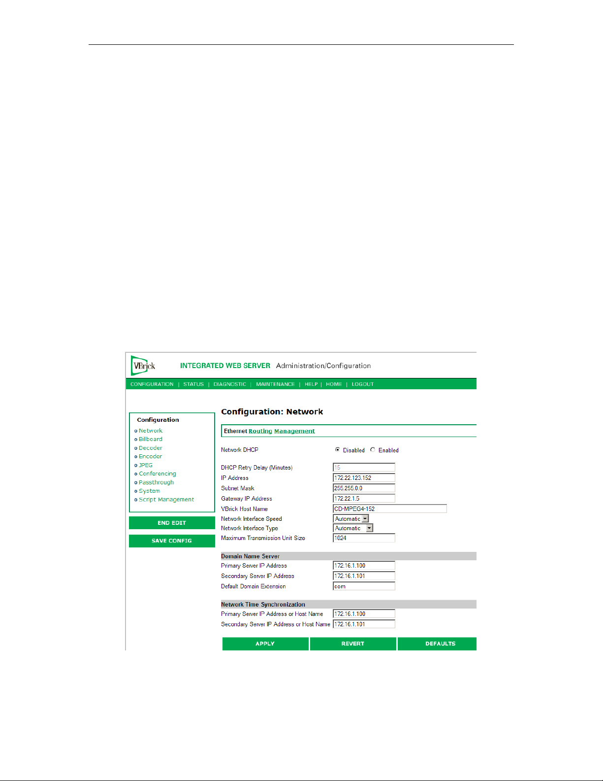
Network DHCP Dynamic Host Configuration Protocol – (Enable, Disable). On
Ethernet models, if DHCP is enabled, the VBrick gets its IP
Address or Network Timer Server and Subnet Mask from the
DHCP server. If the DHCP server supplies the Gateway Address
or DNS server address, these parameters will replace the user
entered Gateway and DNS Time Server settings. If DHCP is
enabled and the VBrick cannot obtain an IP address from the
server, the VBrick will start in limited run mode after two
minutes, using its default IP Address of 172.17.5.5. After 15
minutes, it will automatically reset and again attempt to acquire
an address. The LCD screen on the front of the VBrick will
indicate a DHCP failed message. Note: The VBrick appliance
requires a minimum DHCP lease length of 8 minutes to work,
however it is recommended to extend the lease time to what is
maximally available via the network to avoid disruptions.
DHCP Retry Delay See above. Use to adjust the time before the appliance will reset
and attempt to acquire an IP address. Range 3–15. Default = 15.
IP Address IP Address of the VBrick.
Subnet Mask Subnet mask for the VBrick address.
Gateway IP Address Valid gateway IP Address for communicating across distinct
network segments. A valid gateway IP address is essential even
though the VBrick will operate without one in some cases. When
no gateway is configured, the VBrick may be unable to
communicate with off-net IP hosts, for example, a foreign host
which is used for configuration management via IWS.
VBrick Host Name The Host Name defaults to the Media Access Control (MAC)
address, a hardware address that uniquely identifies each node of
a network. The VBrick's Host Name acts to identify the VBrick
to various network applications including DHCP, SNMP and
VBrick application tools. Note: The Host Name syntax can be a
maximum of 18 characters, the first character must be a letter and the rest
can be letters, numbers or hyphens.
VBrick MPEG-4 Appliance Admin Guide 5
Page 16

Network Interface
Speed
Note: The settings for Interface Speed and Interface Type are
interdependent. They must both be set to Automatic or they
must both be set manually. Manual settings should be used only
in the rare case when the VBrick is attached to network
equipment that does not support auto negotiation. The VBrick's
capabilities may be limited when its Ethernet link is at 10 Mbps
and/or Half Duplex. If auto negotiation fails, the VBrick defaults
to 10Mbit, half duplex and attempts "parallel detection," an
alternative way to sense speed. Status parameters are available on
the network status screen to indicate the state of the link and the
current configuration of the Ethernet hardware. In auto mode,
they reflect the results of the negotiation and in manual mode
they follow the configuration options.
(10Mb, 100Mb, Automatic). This allows the Ethernet interface of
the VBrick to be manually forced to 100 Mbps or 10 Mbps. The
default setting is
Automatic which enables auto negotiation in the
VBrick so it will automatically match its speed setting to the
speed of the switch or hub to which it is attached.
Automatic is
the default and recommended setting.
Network Interface Type Half-Duplex/Full-Duplex/Automatic. This allows the Ethernet
interface of the VBrick to be manually forced to Full Duplex or
Half Duplex. The default setting is "Automatic" which enables
auto negotiation in the VBrick so it will automatically match its
duplex setting to that of the switch or hub that it is attached to.
Automatic is the default and recommended setting. In order for
the Network Auto Negotiate feature to work effectively, the
Ethernet switch must also support auto negotiation. A manually
configured switch will only allow the VBrick to discover the
connection speed—not the mode (full or half duplex).
Maximum Transmission
Unit Size
Range 1024–1500 (default = 1500). The MTU is used for all
network traffic from the VBrick and defines the largest network
packet size that will be transmitted. A higher MTU brings higher
bandwidth efficiency and VBrick recommends using the default.
However you may wish to reduce MTU size to meet the
requirements of some networks with VPN or other security
tunnels that cannot tolerate 1500-byte packets.
Domain Name Server
Primary Server IP
Address
Secondary Server
IP Address
Default Domain
Extension
6 © 2009 VBrick Systems, Inc.
This is the primary server used for DNS.
This is the secondary server used for DNS.
This is the domain name used for DNS. Note that you can use the
default (blank) values for these items.
Page 17

MPEG-4 Configuration
Network Time Synchronization
These fields are used to synchronize network time using the host name or IP address of a
known server to provide a synchronized time for all appliances in the network. To enable
Network Time Synchronization after these parameters are set, go to Configuration: System >
General on page 47 and check the box.
Note To Network Administrators. DHCP Option 4 is used by the DHCP server to return
SNTP server addresses. This option must be enabled in the DHCP server for these
addresses to be returned to the VBrick. If the DHCP server configuration is unknown,
it is recommended that the address(es) be manually entered since the DHCP serversupplied address will always override a manually-entered address.
Primary Server IP Address
or Host Name
Primary host name (VBrick Host Name or DNS Host Name)
or IP address of valid SNTP server providing time
synchronization. A blank field indicates the server address
Network
Secondary Server IP
Address or Host Name
will be acquired via the DHCP server only if the
field above is checked.
DHCP
Secondary host name (VBrick Host Name or DNS Host
Name) or IP address of valid SNTP server providing time
synchronization. A blank field indicates the server address
will be acquired via the DHCP server only if the
DHCP
field above is checked.
Network
Configuration: Network > Routing
The MPEG-4 Appliance requires no routing configuration for the vast majority of network
uses. Use these settings only in those rare cases when your network requires advanced routing
features in the appliance.
VBrick MPEG-4 Appliance Admin Guide 7
Page 18
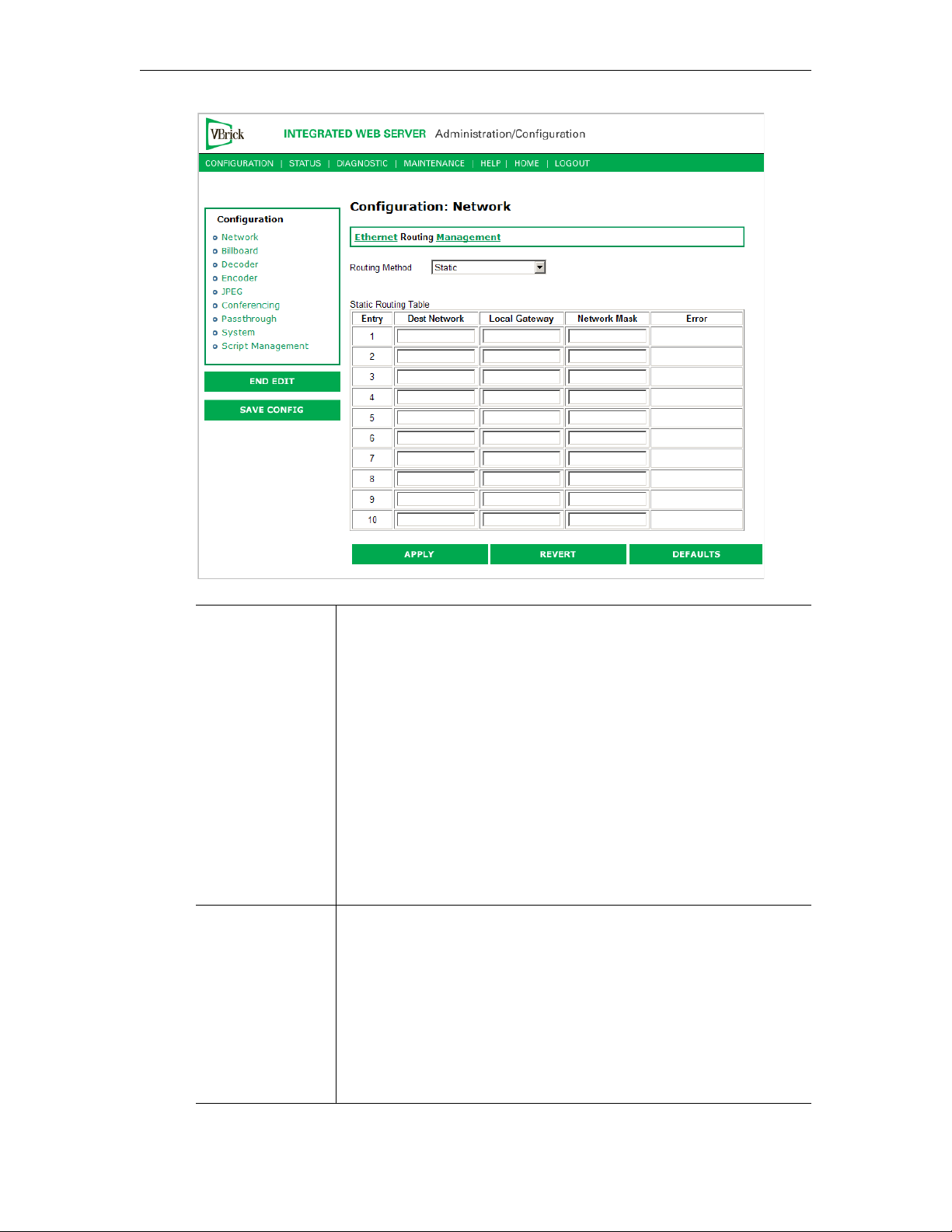
Routing Method This selects which routing method will be used: Changes made to the
Routing Method will require a reset of the box.
• Static – Allows routes entered in the static routing table to be
automatically applied to the internal routing tables, after a powerup.
• RIP Version 1 – Configures the VBrick to listen to RIP
announcements. Routes are dynamically added per RIP
specification.
• RIP Version 2 Broadcast – Configures the VBrick to listen to RIP
version 2 announcements. In this mode, RIP will perform classless
routing based upon subnet mask.
• RIP Version 2 Multicast – Configures the VBrick to listen to RIP
version 2 announcements that are sent in multicast mode. Both
broadcast and multicast announcements are processed.
Static Routing
Table
This table provides for user defined routing entries.
• Destination Network – Enter the destination address to be
manually routed.
• Local Gateway IP – Enter the Gateway to be used, when the
forwarding destination address is as specified.
• Network Mask – Sets the network mask to be associated with the
destination address.
• Error – This read-only field is used to report field entry error
related to the route.
8 © 2009 VBrick Systems, Inc.
Page 19
MPEG-4 Configuration
Configuration: Network > Management
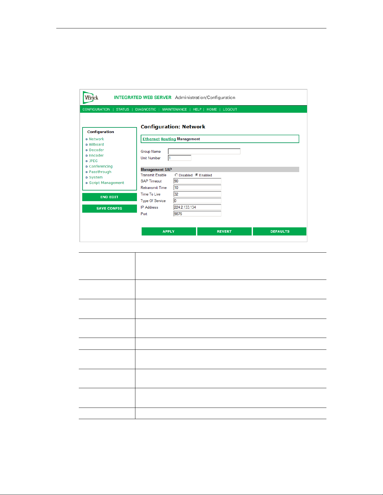
These parameters define information used in the SAPs emitted by the VBrick, which are
received by the VBDirectory management tool (see the VBDirectory User Guide) and other
VBrick applications such as the ETV Portal Server.
Group Name Optional. This parameter defines the Group Name. It is included in
the Management SAPs used by VBDirectory. It is used for organizing
VBricks into groups to simplify use of VBDirectory.
Unit Number Optional. The appliance unit number (range 0–2147483647) is used to
identify each VBrick in a group.
Management SAP Used by VBDirectory or MCS to detect the unit for the purpose of
remote management. The following parameters apply.
Transmit Enable This parameter controls the transmission of the Management SAPs
(Enable or Disable).
Retransmit Time This parameter defines the Management SAP Retransmit Time.
Time to Live The number of hops (between routers) for which a Management SAP
is valid on the network.
Type of Service The TOS (Type of Service) can be configured in the IP header to
establish packet priority in the network.
IP Address This parameter defines the Destination IP Address for Management
SAPs.
Port This parameter defines the Destination Port for Management SAPs.
VBrick MPEG-4 Appliance Admin Guide 9
Page 20
Configuration: Billboard
The Billboard feature allows you to display text and/or graphics on a TV monitor. The
displayed billboard can span multiple pages with each page displayed for a specified period of
time. Some uses of the billboard feature are to announce a daily calendar of events, directions
to a particular conference room or even a slide presentation in conjunction with displayed
video. VBrick models 62xx, 52xx and 53xx have a built in mini-browsers that support viewing
limited HTML pages. The pages can either be kept inside the VBrick as part of the file
system, or can be located on a remote HTTP server. Each page of the billboard is built using
an HTML page with text and graphics created using the HTML tags supported. If billboard is
to be supported on a remote server, the appliance requires read access to the HTTP server
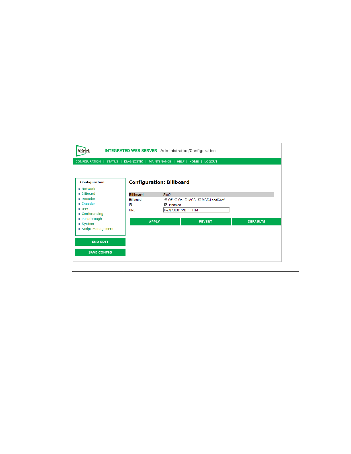
and may need to be configured. The following URL example shows the default page preconfigured by VBrick.
On/Off Turn Billboard on or off.
MCS Reserved for future use; MPEG-4 only. Sends all IR Remote
commands to the browser for processing except for Reset, Slot1 and
Slot2.
MCS-LocalConf Reserved for future use; MPEG-4 only. Sends all IR Remote
commands to the browser for processing except for Reset, Slot1,
Slot2, Previous, Ans Call, Rej Call, Ring-RMT, Ring-DIS, Ring-ENB,
and Hang Up.
Using the Billboard
Billboard may be invoked in several ways. Either use the PC browser to communicate with
the VBrick Integrated Web Server (see separate section) to apply the billboard and turn it on
and off, or press the Billboard key on the optional remote control to toggle it on and off. Use
of the remote can be enabled or disabled through the configuration. Using IWS (or the
VBrick SDK) an administrator can turn on a particular billboard remotely, and prevent
anyone else from using a remote to toggle it on/off. If you have a dual decoder system, the
remote has keys to select between two decoders.
10 © 2009 VBrick Systems, Inc.
Page 21

MPEG-4 Configuration
By turning the billboard on/off, the saved URL is invoked and the browser will attempt to
display the resulting page. The URL can be configured to be a local file with the prefix ‘file:/
/' or point to remote server with the prefix http://. The default billboard is assumed to be a
file located within the VBrick file system, file://./BB01/VB_1.HTM. If the billboard URL
points to a file within the VBrick, the filename has to follow the DOS 8.3 filename
convention (i.e. limited file name length). The valid extensions supported by the billboard are
.HTM, .JPG, .GIF, and .BMP. It is common for the billboard pages to have an .HTM
extension. Remote URLs are restricted to 255 characters.
Billboard FTP
It is possible to use FTP (File Transfer Protocol) to modify the contents of one of the preconfigured Bulletin Board files resident on the VBrick. Use the browser to FTP files, or any
of the many FTP applications. Enter in the browser window:
FTP://xxx.xxx.xxx.xxx (where x is the IP address of the VBrick appliance).
Use the Username and Password (default is case sensitive admin, admin) to login to the
VBrick. BB01 through BB16 are directories established to receive Billboard content. It is
possible to cut and paste new contents to a Billboard location from a file located anyplace on
the network or on the computer. To view the contents on the VBrick, change the URL in the
Billboard Section of the Integrated Web Server. In this example, the URL for the new file in
IWS Configuration: Billboard would read:
file://./BB03/atm.gif.
Billboard URLs
A URL for the billboard is much like a URL on the Internet. URLs can be local or remote,
and typically point to the source of the billboard to be displayed.
Local URL
A local URL points to a file within the VBrick, which can be downloaded to the VBrick using
a FTP utility program. All local URLs begin with: file://. There are sixteen pre-configured
directories to place custom billboards inside the VBrick. The billboard directories are named
BB01 to BB16.
Example 1
A single page billboard is placed in BB01. It requires one image file. The billboard page is
named VB_1.HTM. The URL, which is not case sensitive, to enter in the Billboard URL box
is: file://./BB01/VB_1.HTM
Example 2
A multi-page billboard is placed in BB01. It requires four image files, one for each page. The
billboard pages are named VB_1.HTM, VB_2.HTM, VB_3.HTM, and VB_4.HTM. Each file
is connected to the next page within the html file using the legal syntax. The URL to enter in
the Billboard URL box is:
Remote URL
file://./BB01/VB_1.HTM
Example 1
A single page billboard on a remote server with IP Address 172.16.2.79. The name of the
billboard file is VB_1.HTM. The resulting URL is therefore:
VBrick MPEG-4 Appliance Admin Guide 11
http://172.16.2.79/VB_1.HTM
Page 22

Example 2
A single page on a remote server called www.VBrick.com. The folder name is "billboards".
The name of the billboard file is VB_1.HTM. The resulting URL is therefore:
http://www.VBrick.com/billboards/VB_1.HTM
Billboard File Types
The file types supported are html (.htm), JPEG (.jpg), GIF (.gif) and windows bitmap (.bmp).
Progressive GIF and JPEG are not supported. For the mini-browser to display the images,
the images have to be BMP, GIF, or JPG. Dynamically generated web pages are supported as
long as the output is pure HTML and uses HTML tags that are part of the set as described
below. The server side engine must generate the page. JavaScript and VBScript are not yet
supported. Functions that require these features, like "mouseover", or "onclick" are not
supported.
Creating a Billboard
A billboard that fits on one screen (640 x 480 resolution) can be created using the following
HTML tags:
A
AREA
B
BASE
BIG
BLOCKQUOTE
BODY
BR
CAPTION
CENTER
DD
DIR
DL
DT
EM
FONT
FORM
FRAME
FRAMESET
HEAD
H1
H2
H3
H4
H5
H6
HR
HTML
TH
TITLE
TR
U
I
IMG
INPUT
LI
MAP
MENU
META
NOBR
NOFRAMES
OL
OPTION
P
PRE
SCRIPT
SELECT
SMALL
STRONG
STYLE
TABLE
TD
TEXTAREA
UL
The billboard text generated by the browser is Times Roman. The Font sizes supported are
<Font Size = 1> to <Font size = 7>. Background color and images are also supported. The
standard HTML 16 color palette can be referred to by name, and other colors will be
matched to the nearest color of a standard 232-color template. When creating billboards,
please test your billboard for effect on all types of monitors on which it is going to be
presented. S-Video output and Composite output from the V-Brick are supported.
Video Input
S-Video output from the VBrick to S-Video Input on the television yields the best picture to
the TV monitor. If you do have S-Video input into your television set, it is recommended you
use the S-Video output from the VBrick to the television. Most televisions also support
composite input. The overlay image as used in the billboard can sometimes have the effect of
"flicker" if the font is too small and used on a regular television. This is a product of the
output video signal and the television. On higher-grade monitors, the effect is significantly
reduced.
Font Sizes
It is recommended that font size 5 be used on the billboard. The VBrick has two types of
video output signals. If S-Video out is used, the picture is significantly better than the
12 © 2009 VBrick Systems, Inc.
Page 23

Composite out. Text and graphics tend to appear sharper and do not flicker in S-Video as
much as they do in the composite out. If a flickering effect makes your font unreadable, make
it larger. Making the font bold or <STRONG> will reduce the effect of the flicker.
• The drawing area for Billboard is about 600X400 pixels.
• With a font size of 7, 8 lines of text fit on the screen.
• With a font size of 6, 13 lines of text lines fit on the screen.
• With a font size of 5, 18 lines of text fit on the screen.
Transparent Background
A web page can be created with a transparent background. The video will show through and
any text or images will appear on top of the video. A custom META tag is used to support this
feature. In the <HEAD> portion of the HTML page, enter the following. The chosen
background color will then be overwritten by the transparent color.
<META HTTP-EQUIV="TRANSPARENT" CONTENT="YES">
Configuration: Decoder
Configuration: Decoder > Video
MPEG-4 Configuration
MPEG4 Decoder Video
Decoder Video Format The format can be configured to be NTSC (30fps) or PAL
(25fps).
Logo Display Allows the user to display the VBrick logo on the decoder output
(monitor). The
allows the user to configure a customized logo. The file is simple
HTML and supports local or remote .gif and .jpg files. HTML is
used to provide transparency, blending and placement of the
logo. See Changing the Logo
VBrick MPEG-4 Appliance Admin Guide 13
logo.htm file located in the Logo directory in flash
below for details.
Page 24

Upscale Limit The decoder can resize (scale) the received video image from the
encoder to one of 3 choices – full screen, max scale to 2X and
max scale to 4X.
Display Mode The decoder can display the received video in one of three
modes: Letterbox, Crop, Stretch. This option is rarely used as
VBrick encoded video is produced in 4:3 format.
Image Enhancement
Options
There are several auto enhancement options that the decoder can
apply to help improve the quality of the video being displayed.
The auto modes will remove filtering for higher rate streams
where the filtering will reduce detail. A manual mode is also
provided to allow the user to fine-tune the video. The deblocking filer reduces macro-blocking, the de-ringing filter
reduces the noise commonly seen around the edges of a video
object and the low pass filter reduces high frequency noise. A
combination of
Pass Filter
Deblocking and Deringing, and Adaptive Low
can only be set in manual mode.
Changing the Logo
VBrick MPEG-4 decoders provide an option to superimpose a logo over the output stream
in the lower-right corner of the display. If the logo option is selected, the decoder will output
the default VBrick logo. You can also replace the default image with a customized logo as
explained here. For reference, t
Size 151 x 81 pixels
Blending 50 percent
Transparent (background) color black
Location lower-right corner of screen
he default VBrick logo has the following parameters:
If you use the parameters shown above, the customization process is relatively easy and you
can go to Step 2 below. If you need to change any of these parameters, however, you must
follow all of the steps listed below.
T To change the logo image
1. Create a new
logo.htm page (this page acts as a frame for the logo image). Create the new
file by using the template and instructions provided below in the Modifying the logo.htm
File. You can use any text editor to create this page.
2. Create a new
logo620.gif file. You can use any image processing software as long as
you observe the following guidelines.
File name logo620.gif
File type .gif
Size Modify as necessary. Use the default logo (151x81 pixels) as a reference.
Color It is a good idea to keep black as the background color if the new logo
does not contain any black elements. If you change the background
color, you need to change the corresponding settings in
14 © 2009 VBrick Systems, Inc.
logo.htm.
Page 25

MPEG-4 Configuration
Background Do not use anti-aliasing on the background of the image. There should
be no smoothing of the edges on the lines that meet the background.
3. Upload the new logo to the decoder. The file(s) created in the previous step(s) have to be
FTPed to the VBrick decoder as follows:
a. Open an FTP application, point to the IP address of the VBrick decoder, and login
using the admin user name and password.
b. Copy the file(s) created in the previous step(s) to the
Logo folder on the appliance.
Be sure to keep the existing filename(s).
4. Activate by setting the
Logo Display to On and check the result. To display and verify the
new logo, reboot the decoder as follows:
a. Log into the decoder with a valid user name and password.
b. In IWS, go to
Diagnostics, then click Begin Edit and Reset Box.
c. Wait until the decoder reboots and verify that the image and location are ok.
d. If you need to make changes, go back to Steps 1 or 2, as appropriate, modify the
file(s) accordingly, then repeat steps 3 and 4.
Modifying the logo.htm File
The content of the logo.htm file is shown below. You can get this file, via FTP, from the Logo
folder in the appliance. The only values you may need to edit are highlighted as follows. The
coordinates of the top-left corner of the logo are shown by the numbers highlighted in
for NTSC
top edge of the screen); the second number (
or Blue for PAL. The first number (420/380) is the default vertical Offset (from the
489/489) is the default horizontal offset (from
Red
the left edge of the screen).
The value highlighted in
Magenta sets the blending factor. The valid range is 0–255 with the
default setting being at about 50 per cent. The values highlighted in Black set the transparent
color. The default value is (0, 0, 0) for Black. This setting appears in two places: in numeric
format for the transparent color of the logo image, and in text format where the background
color of the html page is set.
Note When you reload or upgrade the appliance software, a customized logo will be
replaced with the standard VBrick logo. Save your custom logo files in a protected
folder. You will need to replace the logo after a software upgrade.
<html>
<head>
<title>Logo</title>
<meta http-equiv="Content-Type" content="text/html; charset=iso-8859-1">
<style type="text/css"></style>
<script language="JavaScript">
function setupTvScreen()
{
var reso;
reso = GetResolution();
if (reso == 'pal')
{
document.getElementById("PALLogo").style.top = "420px";
document.getElementById("PALLogo").style.visibility = "show";
}
else
{
document.getElementById("NTSCLogo").style.top = "380px";
document.getElementById("NTSCLogo").style.visibility = "show";
}
NavMode('TAB');
VBrick MPEG-4 Appliance Admin Guide 15
Page 26
SetFullScreen();
SetFlickerFilter (1);
SetBlend (100, 125, 0);
SetTransparentColor (0, 0, 0);
SetTransparentColorOn ();
}
</script>
</head>
<body BGCOLOR="Black" ONLOAD="setupTvScreen()">
<div id="PALLogo" style="position:absolute; z-index:1; top: 0px; left: 489px;
visibility: hidden;"><img src="logo620.gif"></div>
<div id="NTSCLogo" style="position:absolute; z-index:1; top: 0px; left: 489px;
visibility: hidden;"><img src="logo620.gif"></div>
</body>
</html>
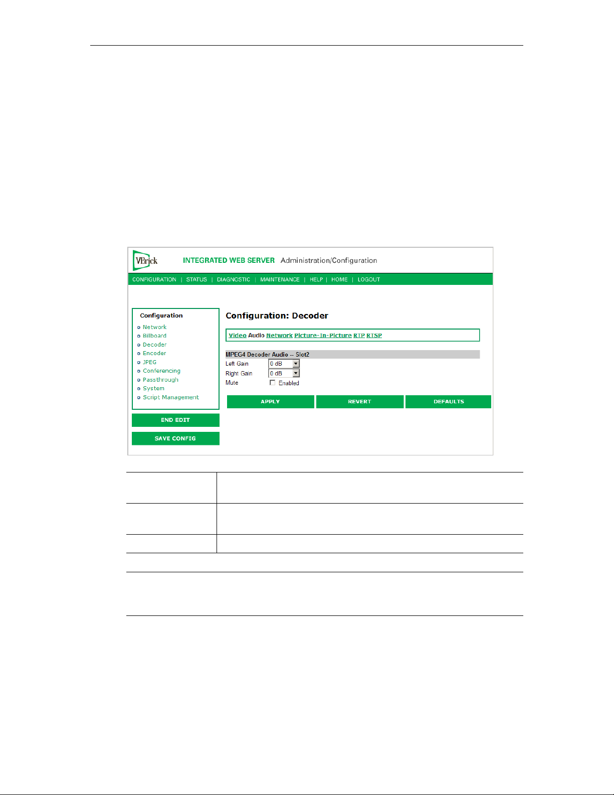
Configuration: Decoder > Audio
Left Gain Used to adjust audio output gain (volume). Range is +12 to –34.5.
Default is 0.
Right Gain Used to adjust audio output gain (volume). Range is +12 to –34.5.
Default is 0.
Mute Used to mute the audio output to the TV or monitor.
Note When receiving streamed audio from a VBrick encoder, the audio level at the decoder
output may differ from the level presented to the encoder by a factor of 4.5dB. Set the
Audio Input Level on the encoder to Alternate if this is an issue.
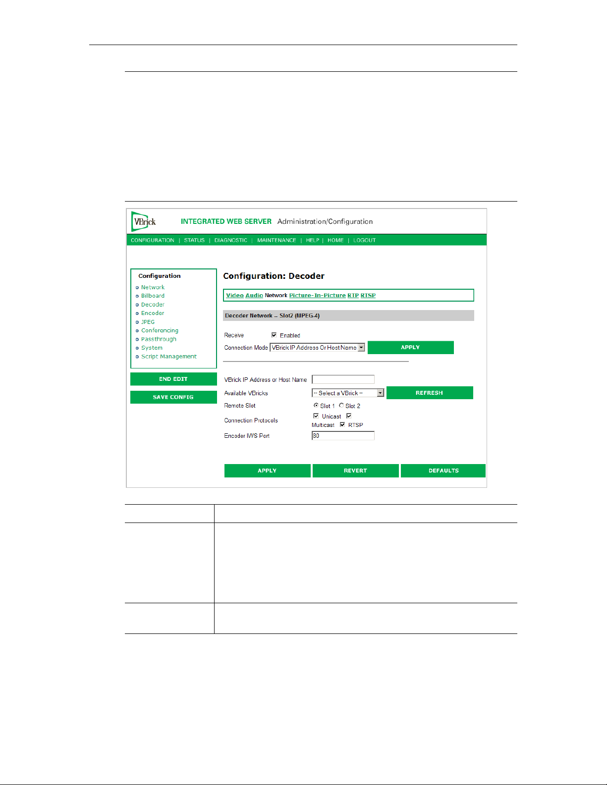
Configuration: Decoder > Network
The decoder connection mode automatically configures the page to display the appropriate
options for each of the modes. The one shown below reflects
mode and its associated settings. All connection modes include the ability to disable
reception via the Receive checkbox.
16 © 2009 VBrick Systems, Inc.
VBrick IP Address or Hostname
Page 27
MPEG-4 Configuration
Note Source-specific multicast is enabled by IGMPv3 and provides a way to share a limited
number of multicast addresses on IGMPv3 networks. It lets your decoder associate a
multicast address with a specific source encoder IP address. Source-specific multicast
is designed for multicasting across networks and has no benefit when sharing multicast
addresses on the same subnet (unless your router supports IGMPv3 snooping).
Multicast addresses in the 232/8 (232.0.0.0 to 232.255.255.255) range are reserved for
source-specific multicast. Enter the multicast address as the "Destination IP Address
or Host Name" parameter on the Configuration: Encoder > Destination IWS page.
There is no other configuration for source-specific multicast on MPEG-4 encoders or
decoders.
Receive This option enables or disables the decoder.
Connection Mode There are several choices for telling the decoder how to connect to a
stream. In order to make other options visible you will need to select
the Connection Mode you want to use and click
Address or Hostname
mode when applied gives you a drop-down list
Apply. The VBrick IP
called Available VBricks that will list all available encode sources. See
examples that follow for other Connection Modes.
Remote Slot The unit may contain dual decoders so you must select the appropriate
slot which represents decoder #1 or decoder #2.
VBrick MPEG-4 Appliance Admin Guide 17
Page 28
Connection
Protocols
Encoder IWS Port The decoder will try to extract the SDP information from the host
The VBrick can connect to the encode source in three ways: Unicast,
Multicast, RTSP. The VBrick decoder will attempt to connect in this
order. Once the connection is established, if for some reason the
connection is lost, the decoder will attempt to reconnect automatically.
Note: When tuning to an encoder that is unicasting to this decoder via
a Firewall/ NAT, only the unicast option should be enabled. Address
resolution behind a NAT/Firewall may make it difficult for the
decoder to match the sender's IP address. Selecting only Unicast will
help alleviate the issue.
using an HTTP get. The host may not be running on port 80 to supply
the HTTP based SDP and may be running on a different port.
Management SAP information may contain the host's HTTP port.
The port value in the SAP overrides the configured HTTP port
through this parameter when requesting HTTP data from the device.
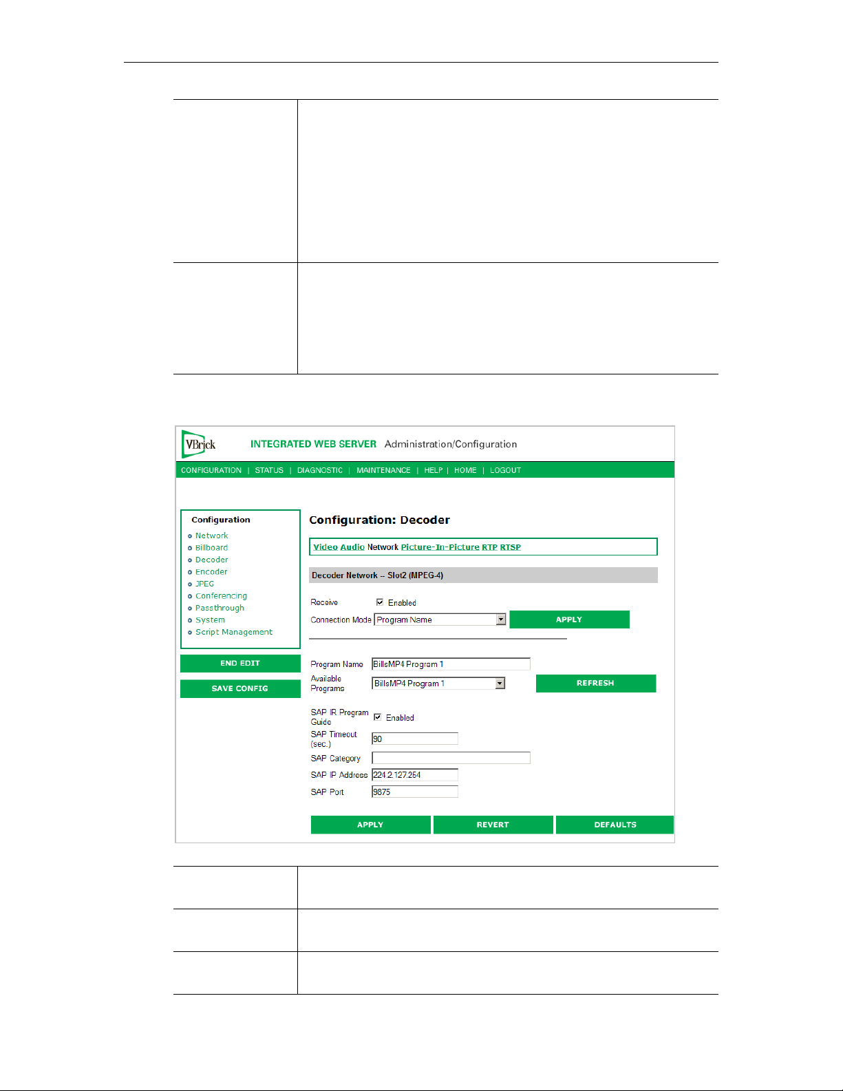
Connection Mode: Program Name
Connection Mode Program Name. In this example the decoder will try to connect to the
encoder with the program name "BillsMP4 Program 1."
Available Programs A drop-down list for available programs is automatically created from
other active devices on the network.
SAP IR Program
Guide
18 © 2009 VBrick Systems, Inc.
A program guide of available streams can be displayed on the TV or
monitor using the IR remote.
Page 29
MPEG-4 Configuration
SAP Timeout This is the amount of time before a transmitted SAP will automatically
timeout on the network.
SAP Category Certain streams can be protected by being transmitted with a category
string e.g. "financial." VBrick decoders will not see these protected
streams unless this unique string is entered in the SAP category field.
Note: Characters are ASCII and are case sensitive. The total of all
keywords in the string is 36 characters including spaces.
SAP IP Address This will be the address that the SAP information is transmitted on.
SAP Port This will be the port that is associated with the SAP IP address.
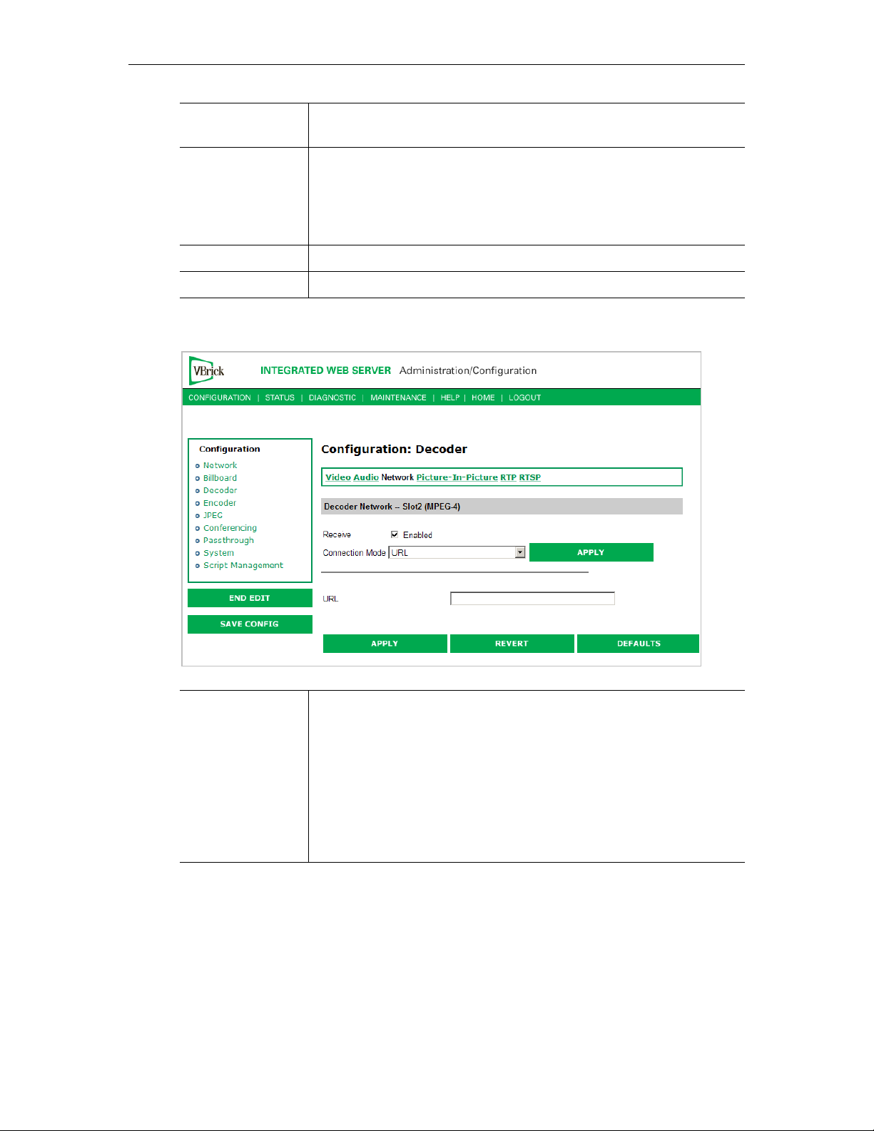
Connection Mode: URL
Connection Mode URL. In this example the decoder will try to connect to the server
according to the URL defined here. This URL could be that of the
MP4 VBrick encoder or a Darwin server (for example). The encoder
needs to be specified by its IP Address or Fully Qualified Domain
Name. If you point this to an NXG Server the RTSP Location is case
sensitive (i.e. /brian/The-Others). Some Legal URL examples include:
rtsp://192.168.1.4/vbrickvideo1
rtsp://frodo.vb.loc/brian/The-Others
http://192.168.1.4/vbs1d1.sdp
Connection Mode: SDP on Flash
SDP (Session Description Protocol) files contain information about the format, timing, and
authorship of the streamed media. SDP files are created on the VBrick appliance during
streaming. In most cases the SDP file should not be modified manually; however, under some
circumstances that might be necessary. If the streamed file changes, the SDP file can be
deleted and re-created. An SDP file is not saved with an extension (*.sdp) so that Internet
Explorer will run the file rather than allowing it to be saved. You can add the .sdp extension
manually if it needs to be recognized by non-VBrick decoders.
VBrick MPEG-4 Appliance Admin Guide 19
Page 30
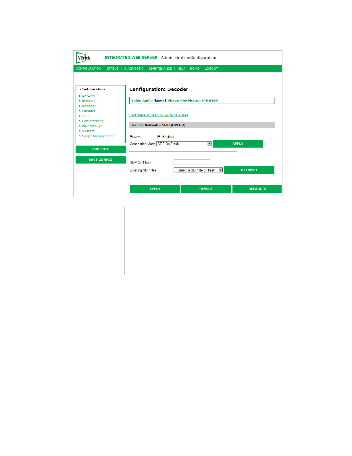
Connection Mode SDP on Flash. In this example the decoder will try to connect to the
encoder defined in the SDP file located in the decoder's flash memory.
Existing SDP Files The user/administrator can browse the SDP files that are located in
the decoder's flash memory and selects one to use from the dropdown list.
Click here to read
or write SDP files
This will launch an external FTP window used to access the flash
memory SDP files in the decoder's flash memory. Username and
password are both "admin" by default.
Connection Mode: Loopback from Encoder
20 © 2009 VBrick Systems, Inc.
Page 31
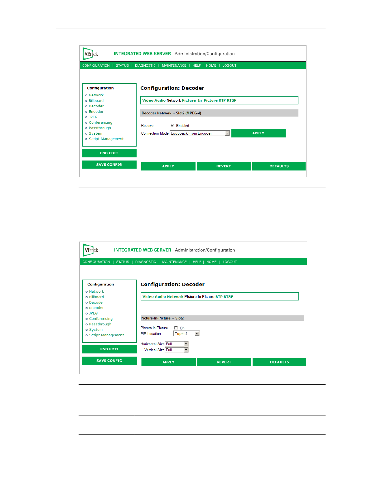
MPEG-4 Configuration
Connection Mode Loopback from Encoder - In this example the decoder will display
video from the local encoder (option only valid if encoder is present,
i.e. VB6200 encoder/decoder model).
Configuration: Decoder > Picture-In-Picture
Picture in Picture On/Off. This will enable or disable the Picture-In-Picture display.
PIP Location Picture-In-Picture can be any of the following 5 locations - top left,
top right, bottom left, bottom right and center.
PIP Horizontal
Size
PIP Vertical Size The Picture-In-Picture vertical size can be changed to any of the
VBrick MPEG-4 Appliance Admin Guide 21
The Picture-In-Picture horizontal size can be changed to any of the
following 4 sizes – full, half, quarter, thumbnail.
following 4 sizes – full, half, quarter, thumbnail.
Page 32
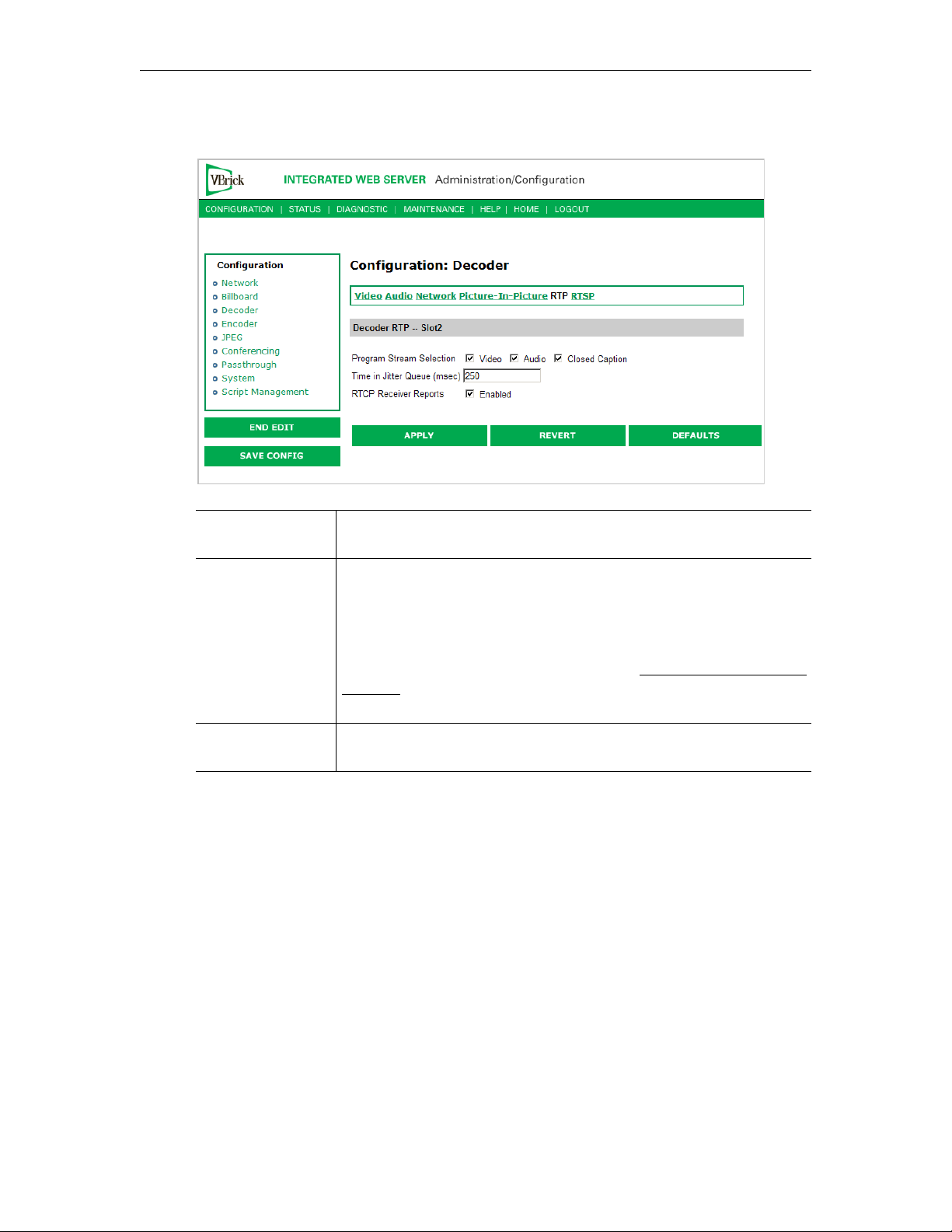
Configuration: Decoder > RTP
Program Stream
Selection
Time in Jitter
Queue
RTCP Receiver
Reports
The decoder can be configured to request an audio-only, video-only or
closed caption stream.
The jitter queue is a buffer which will fill up in case of network
latency. This is helpful when connecting over networks which exhibit
non-linear data transmission such as the public internet. The jitter
queue is adjustable. The higher the value, the more jitter the decoder
can handle but at the cost of overall latency (delay). The range is from
0 to 5000 milliseconds. Default is 250ms. See Status: Decoder Status >
Network on page 69 for details about Jitter Queue Underflow and
Jitter Queue Overflow.
When enabled, the decoder client will send RTCP receiver reports to
the server. This is sometimes used as a keep-alive for the server.
Configuration: Decoder > RTSP
22 © 2009 VBrick Systems, Inc.
Page 33
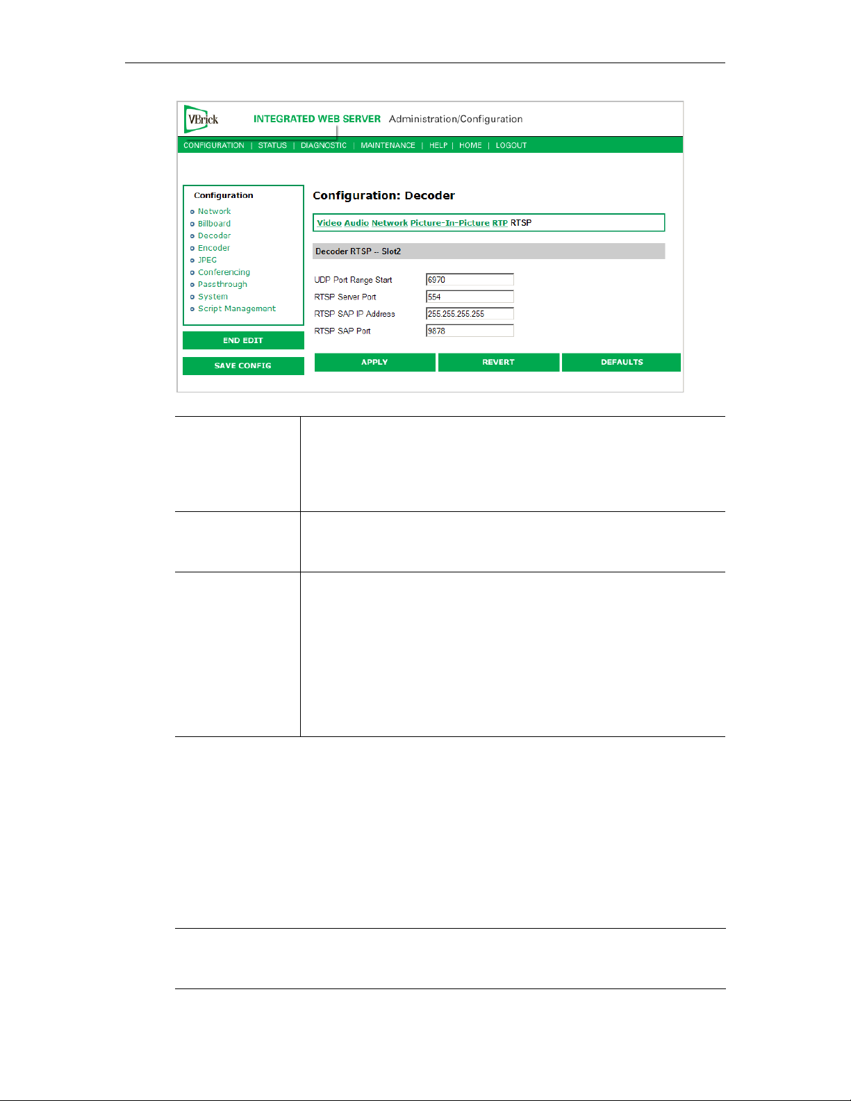
MPEG-4 Configuration
UDP Port Range
Start
RTSP Server Port The decoder uses this TCP port when initiating an RTSP session to an
RTSP SAP IP
Address and Port
The decoder will negotiate with the server which ports are to receive
multimedia presentation material. To receive a presentation which has
audio, video and cc, 6 ports are required, (two ports for each media
type). The start range is 6970 (default) and can be modified by via this
setting.
RTSP video server. Normally, this port called the control port and is
554.
The decoder listens for RTSP URL information advertised in SAP
format, on the address specified by this parameter. Generally, the
encoders send out SAPs with their RTSP URL information using the
address 255.255.255.255 (broadcast to the local subnet). Included with
RTSP SAP IP Address configuration, is a Port parameter, also
configurable. The SAPs received on this IP address/port are included
in the list of program names on the decoder network page when in
program name mode, as well as on the program guide as displayed on
the TV monitor.
Configuration: Encoder
Configuration: Encoder > Template
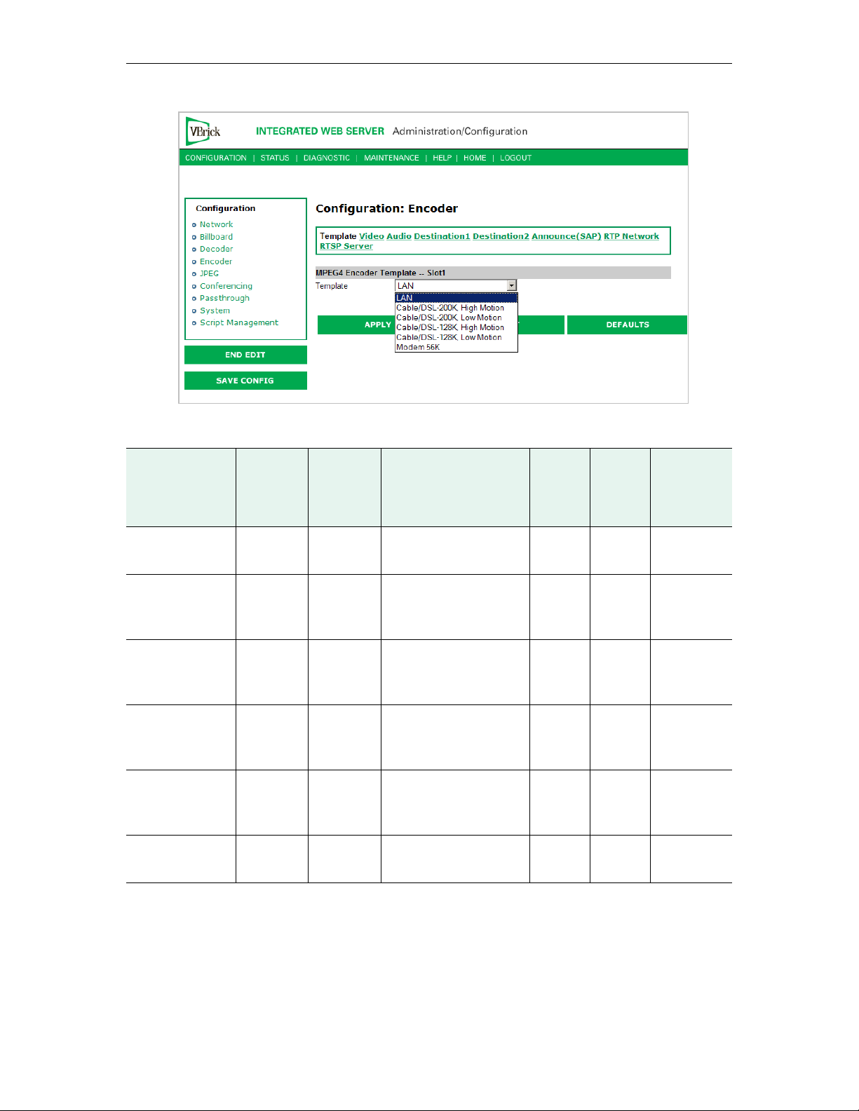
Selectable templates have been preconfigured to fit many applications. There are always trade
offs when selecting encoder settings. In general, the finer the resolution detail and smoother
the motion, more resources are used and the larger the file (when stored). The optimum is to
display the finest detail and smoothest motion possible given the amount of network
resources available to both the sender and to the viewer who is receiving the video streams.
Note When choosing a Template, if the parameters of the Template don't match the current
video parameter settings, there will be a note to that effect under the selection box
stating, Parameters do not match template.
VBrick MPEG-4 Appliance Admin Guide 23
Page 34
Tab le 1 . Templates Table
Template Name Tot al
System Bit
Rate
(Kbps)
LAN 1500 1200 CBR-CFR, SIF, 30 FPS 3 128 48 kHz
Cable/DSL
200K
High Motion
Cable/DSL
200K
Low Motion
Cable/DSL
128K
High Motion
Cable/DSL
128K
Low Motion
Modem 56K 50 20 CBR-VFR, 128x96, 5
200 150 CBR-VFR, 256x192, 15
200 148 CBR-VFR, 256x192, 10
128 78 CBR-VFR, 192x144, 15
128 80 CBR-VFR, 256x192,
Video
Targe t Bi t
Rate
(Kbps)
Major Video Encoding
Settings
FPS
FPS
FPS
7.5 FPS
FPS
Key
Frame
Interval
5 32 24 kHz
5 32 24 kHz
6 32 24 kHz
6 32 24 kHz
10 8 8 kHz
Audio
Targ et
Bit Rate
(Kbps)
Major
Audio
Encoding
Settings
2 channels
1 channels
1 channels
1 channels
1 channels
1 channel
Configuration: Encoder > Video
24 © 2009 VBrick Systems, Inc.
Page 35
MPEG-4 Configuration
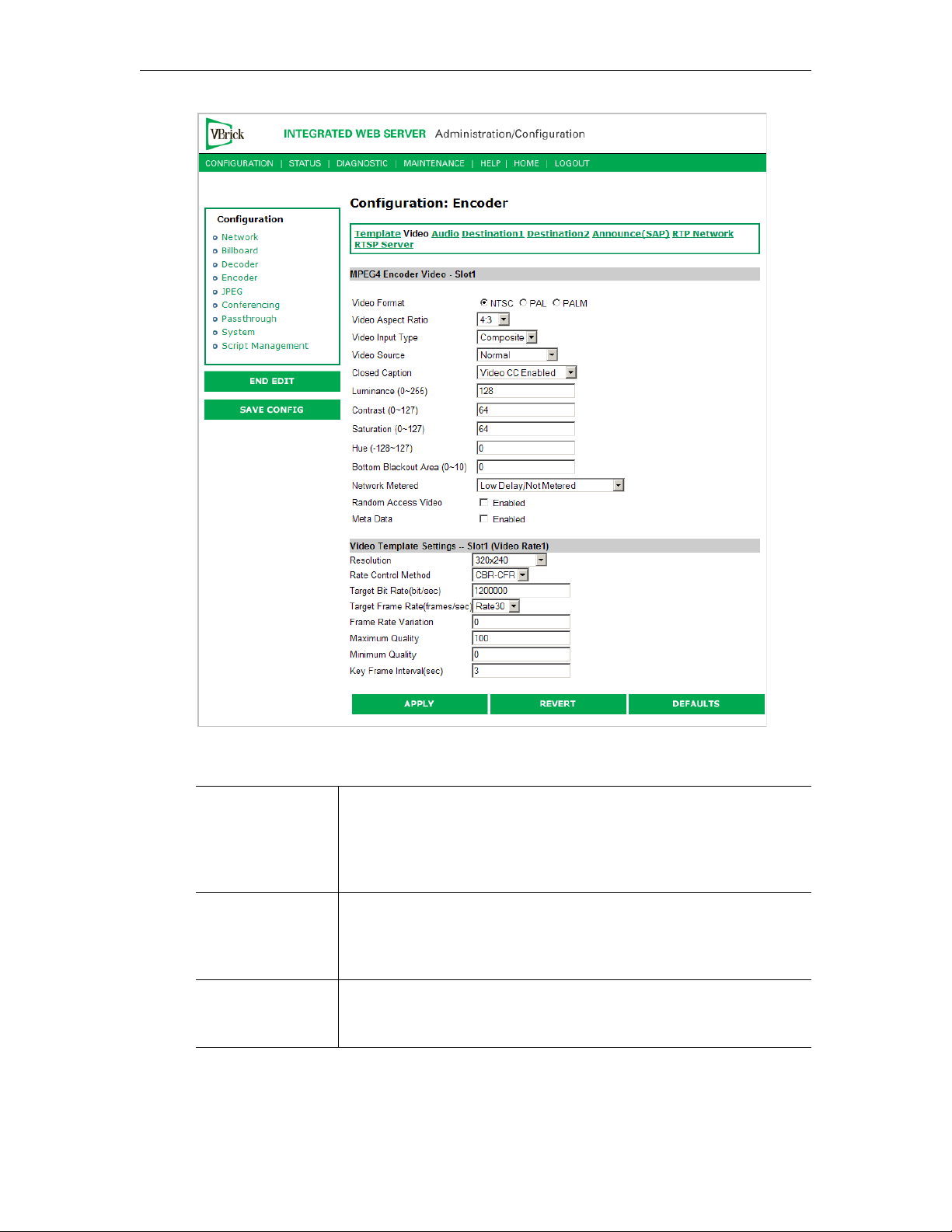
MPEG4 Encoder Video
Video Format The format can be configured to be NTSC (30fps) ,PAL (25fps) or
PALM (30fps). PAL-M is a video format standard used in Brazil. The
main difference between PAL and PAL-M is a lower resolution (525
lines instead of 625) and a higher frame count (30 frames per second
at 60Hz versus 25 frames per second at 50Hz).
Video Aspect Ratio Aspect ratio is the ratio of the width of the image to the height of the
image. Standard TV images generally use an aspect ratio of 4:3; DVD
players and some camera can produce 16:9. Set this value to match the
video input source, either 4:3 or 16:9.
Video Input Type The input can be changed to accept either S-video or composite
(BNC). Note that model 9174-4200 (VBSSM) does not support
S-Video.
VBrick MPEG-4 Appliance Admin Guide 25
Page 36

Video Source This enables the user to select the bandwidth for tracking the video
input.
• Normal – Select for stable sources such as Cable, DVD or camera.
• High Jitter – Select for unstable sources such as VCR or VTR.
Closed Caption This setting enables closed captioning.
• Video CC Enabled – Reads the embedded video closed captioning
text.
• Inserted CC Enabled – Inserts the user defined text set in the
Closed Caption Text field.
Inserted CC
Update Rate
Displayed when Inserted CC Enabled is set. This sets the rate with
which the closed captioning field gets updated for the box (default is
medium). Only works when Inserted CC Enabled is selected for
Closed Caption above.
• Slow – When set to slow, the inserted closed captioning field will
be updated every 60 seconds.
• Medium – When set to medium, the closed captioning field will
update every 20 seconds.
• Fast – When set to fast, the closed captioning field will update
every 5 seconds.
Inserted CC Text Displayed when Inserted CC Enabled is set.Sets the text that is
inserted into the closed captioning field of the encoded stream
(default is "inserted string" \h \d \t \c). Only works when Inserted
CC Enabled is selected for Closed Caption above. Enter any string up
to a maximum of 32 characters (including the Host Name, Date and
Time). No double quotes, less than <, or greater than > symbols are
allowed. Special codes can be substituted for the text in a string as
follows:
• \h or \H – Host Name.
• \d or \D – Current Date.
• \t or \T – Current Time.
• \c# or \C# – Set Color (where # = the number corresponding to
color). 0 = White, 1 = Green, 2 = Blue, 3 = Cyan, 4 = Red, 5 =
Yellow, 6 = Magenta
Inserted CC Row Displayed when Inserted CC Enabled is set. Sets the position on the
screen where the text defined in the Closed Caption Text field will
appear in the decoded video. Can be set from 1 through 15, where 1
indicates the top of the screen and 15 indicates the bottom of the
screen (default is 15), when Inserted CC is enabled.
Luminance 0–255. Default = 128. The luminance is the information about the
varying light intensity of an image, which is best described as
brightness.
Contrast 0–127. Default = 64. The contrast is the range of light-to-dark values
of an image that are proportional to the voltage differences between
the black and white levels of the signal.
Saturation 0–127. Default = 64. The saturation is the spectral purity or intensity
of a color.
26 © 2009 VBrick Systems, Inc.
Page 37

MPEG-4 Configuration
Hue 128–127. Default = 0. The hue is the attribute by which a color may
be identified within the visible spectrum. Hue refers to the spectral
colors of red, orange, yellow, green blue and violet. Note that adding
hue reduces the saturation.
Network Metered If you select
sent as soon an they are encoded. This may result in substantial
network traffic burstiness since certain encoded frames such as video
key frames are much larger than other frames. If
Network Metered
the audio/video/CC resulting in less burstiness from a network traffic
perspective. However, this results in jitter, that is, relative
displacement of the content from a timing perspective. This forces
end-to-end latency to increase. Note that for VBrick decoders, even if
Time in Jitter Queue is set low, the fact that the encoder is
the
metering the data results in an automatic increase in the target latency
to three seconds. Also, the jitter queue may automatically be adjusted
to almost 3 seconds, if the encoder that it is tuned to is experiencing
heavy RTSP client utilization. The encoder automatically informs the
decoder to adjust the jitter queue upwards to accommodate the
additional traffic load. Once the traffic load diminishes the encoder
will re-inform the decoder to reduce the jitter queue delay,
automatically. The VBrick StreamPlayer PC decoders also increase
buffer/latency if the encoded stream is metered. We recommend use
of the Low Delay setting if interactive end-to-end behavior is
required. We recommend the use of metering if the bandwidth in
transmission path is constrained.
Random Access
Video
If this option is enabled; additional header fields are added to the
encoded stream providing the capability for certain third-party videoonly decoders to decode the video stream without externally supplied
SDP information.
Low Delay/Not Metered, frames of audio/video/CC are
Medium Delay/
is selected, the encoder smooths the transmission of
Meta Data When Metadata is enabled a new field will appear on the screen
allowing the operator to insert metadata strings into the video as User
Data. The normal use of metadata is to allow accompanying
synchronized URL references to displayed in rich media applications.
The VBrick StreamPlayer has the capability of extracting the metadata
references and presenting them to an appropriate application. Contact
VBrick for details.
Meta Data Shown if Meta Data is enabled. Maximum 250 characters. Click Insert
Now to insert the meta data string into the stream.
Video Template Settings
The following video settings are affected by choosing a Template in the Configuration:
Encoder > Template section of IWS. For more about templates, see Table 1 on page 24. The
following video settings are affected by a Template setting.
VBrick MPEG-4 Appliance Admin Guide 27
Page 38

Resolution The pixel Width and Height of viewed video on the PC screen (Width
by Height). Regardless of whether the transmission is NTSC or PAL,
the following resolutions are possible:
• 320 x 240
• 256 x 192
• 192 x 144
• 128 x 96
•64 x 48
If NTSC or PAL-M is selected, the following resolutions are available:
• 352 x 240 (SIF)
• 176 x 128 (QSIF)
If PAL is selected, the following resolutions are available:
• 384 x 288
• 352 x 188 (CIF)
• 176 x 144 (QCIF)
Rate Control
Method
The selections are shown below. The interrelations between these
terms are complex. Use of VBR should be restricted to controlled
environments where significant burstiness in the achieved bit rate is
acceptable. Not all players and/or networks may handle high levels of
burstiness. Default is CBR-CFR. The abbreviations refer to:
• CBR – Constant Bit Rate.
• VBR – Variable Bit Rate.
• CFR – Constant Frame Rate.
• VFR – Variable Frame Rate.
Target Bit Rate Bits/second. This number represents how much data the VBrick will
send out each second to carry video to an MPEG-4 player. The word
target is used because the VBrick can vary its bit rate slightly in
response to the amount of detail in the movie or camera output. The
discussion of Rate Control Method has more detail. Note that bit rate
determines how much data the VBrick sends in one second to contain
one second of the video or camera output. The more data the VBrick
sends in one second, the more clearly the details of the movie will be
seen on an MPEG-4 player. It is not always possible to send the most
possible data, since that requires a large network "pipe" (connection).
The trade off is the level of detail in the video with the use of smaller
network connections. The difference between "constant" and
"variable" bit rate is that if "constant" is chosen, then the VBrick will
make a strong effort to ensure that the chosen bit rate is reached as
often as possible. The "variable bit rate" setting allows the VBrick to
change how much data it uses in a second (within limits of course), so
that less complex scenes can be sent using fewer bits.
28 © 2009 VBrick Systems, Inc.
Page 39

MPEG-4 Configuration
Target Frame Rate • NTSC: Rate30, Rate20, Rate15, Rate10, Rate7.5, Rate6, Rate5,
Rate3, Rate2 and Rate1. Default = Rate30.
•PAL: Rate 25, Rate20, Rate12.5, Rate10, Rate5, Rate2.5, Rate1.
Default = Rate25.
This number represents how many frames the VBrick will send out
each second to carry the video to an MPEG-4 player. The word target
is used because the VBrick can vary its frame rate slightly in response
to the amount of motion in the movie or camera output. The
discussion of Rate Control Method goes into this in more detail.
Frame rate is the number of "frames" the VBrick sends in a second for
an MPEG-4 player to display. Moving pictures are made up of a rapid
series of "still" pictures that move so fast that the "illusion" of motion
is produced. A frame is one such "still" picture. Regular TV programs
in the U.S. run at about 30 frames in a second; and the more frames
presented in a second; the smoother the motion contained within the
video will appear. Encoding and transmitting a frame requires the use
of data, so that, when considering a particular bit rate, sending more
frames demands that each frame contain fewer fine details. Similar to
bit rate, the difference between "constant" and "variable" frame rate is
that if "constant" is chosen, then the VBrick will make a strong effort
to ensure that the chosen frame rate is reached as often as possible.
The "variable frame rate" setting allows the VBrick to change how
many frames it uses in a second (within limits of course), so that rapid
motion can play more smoothly.
Frame Rate
Variation
Default = 0 (maximum smoothness). This number indicates to the
VBrick exactly how much it is allowed to vary its frame rate in trying
to reach its target bit rate. Decreasing this number means that motion
will appear smoother, but that the target bit rate will not be met as
closely. This option is used only VFR mode.
Minimum Quality This number tells the VBrick appliance never to lose details in the
video beyond a certain level. Increasing the minimum quality ensures
that more detail will be seen, but that the trade off is that the target bit
rate and frame rate will not be met as closely.
Maximum Quality This number tells the VBrick appliance never to include details finer
than a given level. Lowering the number can be useful for sending less
data when the subject matter of the video has little need for very high
"fidelity".
Key Frame Interval In seconds. This interval allows an MPEG-4 player to "sync up" with a
video stream already in progress by providing basic anchoring and
orienting data. If "key frames" are sent less frequently, it will take
longer for the video to begin playing after an MPEG-4 player is
started on a PC. Key Frames use up a lot of data, lowering the amount
of data available to carry the details of the video, so VBrick appliances
are often set up to send key frames at infrequent intervals.
VBrick MPEG-4 Appliance Admin Guide 29
Page 40
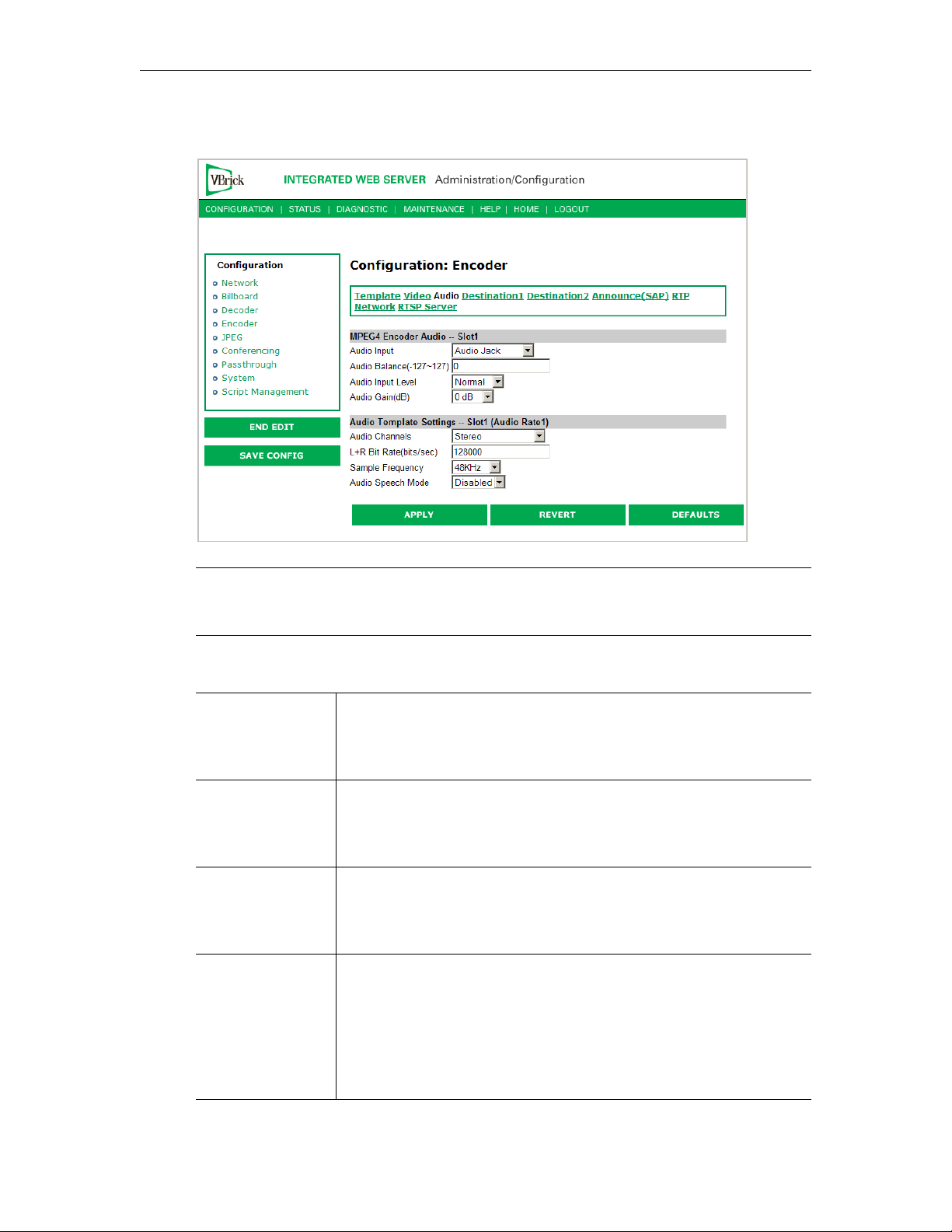
Configuration: Encoder > Audio
Note In Edit mode, the settings that are affected through template settings (set in the
Configuration: Encoder > Template) are set apart on the bottom portion of the
screen.
MPEG4 Encoder Audio
Audio Input Input can be from an Audio Jack (1/8" mini-phono jack) or from
Microphone DIN (AudioMate microphone). Note that audio
attenuation is relevant only if the 1/8" mini-phono jacks are used.
Note that model 9174-4200 (VBSSM) does not support audio.
Audio Balance -127 to 127. Default = 0. This setting controls the balance the output
level between the left and right audio channels, a value of -127 mutes
the right channel and a value of 127 mutes the left. A value of 0
distributes audio levels equally between the left and right channels.
Audio Input Level Normal or Alternate. Default = Normal. Sets the audio level for the
encoder audio jack input. When set to normal, the audio inputs accept
a 4-volt peak-to-peak maximum signal. When set to alternate, the
audio inputs accept an 8-volt peak-to-peak maximum signal.
Audio Gain This setting controls the audio level of the encoder. When the Audio
Input Level is set to Normal, the settings are from 7 to –53 dB and
mute. The default is 0 dB. A setting of 7 is full volume and –53
effectively mutes the encoder. When the Audio Input Level is set to
Alternate, the settings are from 12 to –48 dB and Mute. The default is
0 dB. A setting of 12 is full volume and –48 effectively mutes the
encoder.
30 © 2009 VBrick Systems, Inc.
Page 41

MPEG-4 Configuration
Audio Template Settings
The following audio settings can be changed by choosing a Template setting in the
Configuration: Encoder > Template section of IWS. For more about templates, see Table 1
on page 24. The following settings are affected by a Template setting.
Audio Channels The audio output mode can be configured to 1 of 3 possible settings:
• Stereo – Stereo directs the input left channel to the left channel in
the audio stream and the input right channel to the right channel in
the audio stream. In this mode, the encoder expects that the two
channels are not totally discrete and have audio components that
are common to both the left and right channels. In Stereo mode,
the encoder can compress the audio more efficiently and achieve
higher performance with lower bitrates. Always select Stereo for
DVD/VCR reproduction.
• Mono (left to stereo) – Mono directs the left input channel to both
the left and right channel.
• Dual – Each channel is compressed independently. Two totally
separated channels are compressed and decompressed. Dual is
ideal for voice applications where the microphone input from two
channels is separated to avoid crosstalk.
• Mono (left only) – This option allows only the left input channel to
be carried in the stream. Output is to the left channel only.
L+R Bit Rate
(bits/sec)
Sample Frequency Frequency at which the audio is sampled at the encoder. Settings
Audio Speech
Mode
The value can be set in 2 K increments from 8K to 320K (8000 to
320000 in increments of 2000). The default value is 256,000 bps. This
is the audio encoding bit rate of the audio stream. If the Encoder
Audio Output is set to stereo or mono, the value can be set from
16000 to 320000. The sampling rate is based on the per channel bit
rate:
• Up to 12000, the sampling rate is set to 8kHz.
• 12000 to 30000, the sampling rate is set to 16kHz.
• 30000 to 40000, the sampling rates is set to 24kHz.
• Greater than 42000, the sampling rate is set to 48kHz.
Example. A stereo output bit rate of 48000 uses a sampling rate of
16kHz (the per channel bit rate is 24000). A mono output bit rate
48000 uses a sampling rate of 48k; only one channel is being
transmitted.
include 8, 16, 24, 44.1 and 48 KHz. The default is 48 KHz.
Applications that are low-bit rate (8 to 12kbps) voice only will benefit
from speech mode enabled. This will help reduce any reverb effects.
In all other applications (such as music or voice bit-rates greater than
12kbps) this mode should be disabled.
Configuration: Encoder > Destination 1 & 2
Using Unicast
With one encoder, it is possible to send unicast video and audio to two separate locations
using the Configuration: Encoder > Destination 1 and/or Destination 2 parameters. The
VBrick MPEG-4 Appliance Admin Guide 31
Page 42
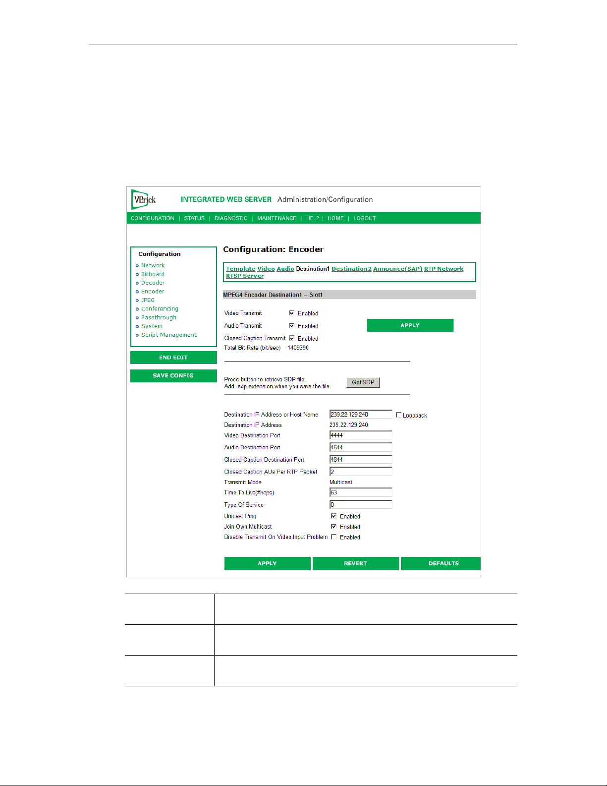
parameters on these two pages allow the same video and audio streams to be sent to two
independent destinations. Each destination is configured for a pair of ports, one for video
and another for audio. To send Unicast, enter the IP Address of the computer to which video
is sent into the
Destination IP Address field.
Using Multicast
To send Multicast, use the same Destination1 and Destination2 settings, but enter a valid
Multicast address in the "Destination IP Address" field.
Video Transmit
Enable
Audio Transmit
Enable
Closed Caption
Transmit Enable
32 © 2009 VBrick Systems, Inc.
Controls whether the primary encoder video output is to be
transmitted to the network.
Controls whether the primary encoder audio output is to be
transmitted to the network.
Controls whether the primary encoder closed captioning is to be
transmitted to the network.
Page 43

MPEG-4 Configuration
Total Bit Rate Bits per second. This parameter reports the calculated total system bit
rate, in bits per second. It includes video and audio (if enabled) along
with packet header overhead.
Get SDP SDP, or Session Description Protocol files, contain information about
the format, timing, and authorship of the streamed media. SDP files
are created on the VBrick appliance during streaming. In most cases
the SDP file should not be modified manually; however, under some
circumstances that might be necessary. If the steamed content
changes, the SDP file can be deleted and re-created.
When the SDP file is saved, it is not saved with an extension (*.sdp).
The reason is that if the file has an extension, Internet Explorer will
run the file instead of allowing it to be saved. If it is necessary for the
file to be recognized by non-VBrick decoders, the .sdp extension can
be added manually.
Destination IP
Address or Host
Name
Destination IP
Address
Video Destination
Port
Audio Destination
Port
Closed Caption
Destination Port
This is the Destination IP Address or DNS Host Name of the
encoded video. When Loopback is enabled the IP Address is set to
127.0.0.1, disable Loopback in order to change this field. The Host
Name should be the Fully Qualified Domain Name. If the name is not
available to the system it will use the Destination IP Address of
127.0.0.1. When this is a Multicast address, the transmit mode reports
Multicast. Similarly, if this is a Unicast address, the transmit mode
reports Unicast. Note that multicast addresses in the 232/8 (232.0.0.0
to 232.255.255.255) range are reserved for source-specific multicast.
Note: The Host Name is resolved using the primary or secondary
domain name server set in Network: Configuration. 127.0.0.1 is used
if it cannot be resolved, or if the entry for DNS is blank.
This read-only parameter informs the operator of the IP Address for
the DNS Host Name input into the Destination IP Address or Host
Name Field.
This is the destination IP port of the network device that will be
receiving the encoded video.
This is the destination IP port of the network device that will be
receiving the encoded audio.
This is the destination IP port of the network device that will be
receiving the encoded closed captioning.
Closed Caption
Aus per RTP
packet
This is the number of frames of closed caption frames (access units)
that are placed in each RTP packet. Since each closed caption frame is
small, if multiple Aus are placed in a single RTP packet the bandwidth
efficiency is improved at the cost of additional latency.
Transmit Mode This read-only parameter (derived from the Destination IP Address)
tells you whether the encoder is transmitting the video stream in
Unicast or Multicast mode. In Unicast mode, if the network portion of
the IP address is outside the scope of the local area network, the
Unicast address is presumed to be outside the network.
Time to Live The number of hops (between routers) for which an IP packet is valid
on the network.
VBrick MPEG-4 Appliance Admin Guide 33
Page 44

Type of Service The TOS (Type of Service) can be configured in the IP header to
establish packet priority in the network.
Unicast Ping Feature for primary destination can be enabled, disabled. If the VBrick
is designated to transmit a transport stream to any destination
(whether another VBrick or not) in Unicast mode, this parameter is
used to instruct the VBrick to ping the destination periodically to test
connectivity before sending the stream. If Unicast Ping is not enabled,
and the destination goes off-line, the Unicast stream may be broadcast
to all destinations on the network, flooding the network. This feature
should only be disabled if the network has a particular requirement
that makes it unworkable.
Join Own Multicast Some network equipment requires that a Multicast source (such as a
VBrick encoder) join its own Multicast group. This feature is enabled
by default and has no adverse affect on equipment that is fully
multicast-supported.
Disable Transmit
on Video Input
Problem
Stop sending and free up bandwidth if there is an interruption for any
reason in video input.
Configuration: Encoder > Announce (SAP)
Contains parameters used to change the SAP (Session Announcement Protocol)
advertisements. SAPs are advertisement packets that are transmitted by VBrick appliances to
other VBrick appliances and VBrick applications such as the Portal Server and
StreamPlayerPlus. They are used to identify streams present in the network.
34 © 2009 VBrick Systems, Inc.
Page 45
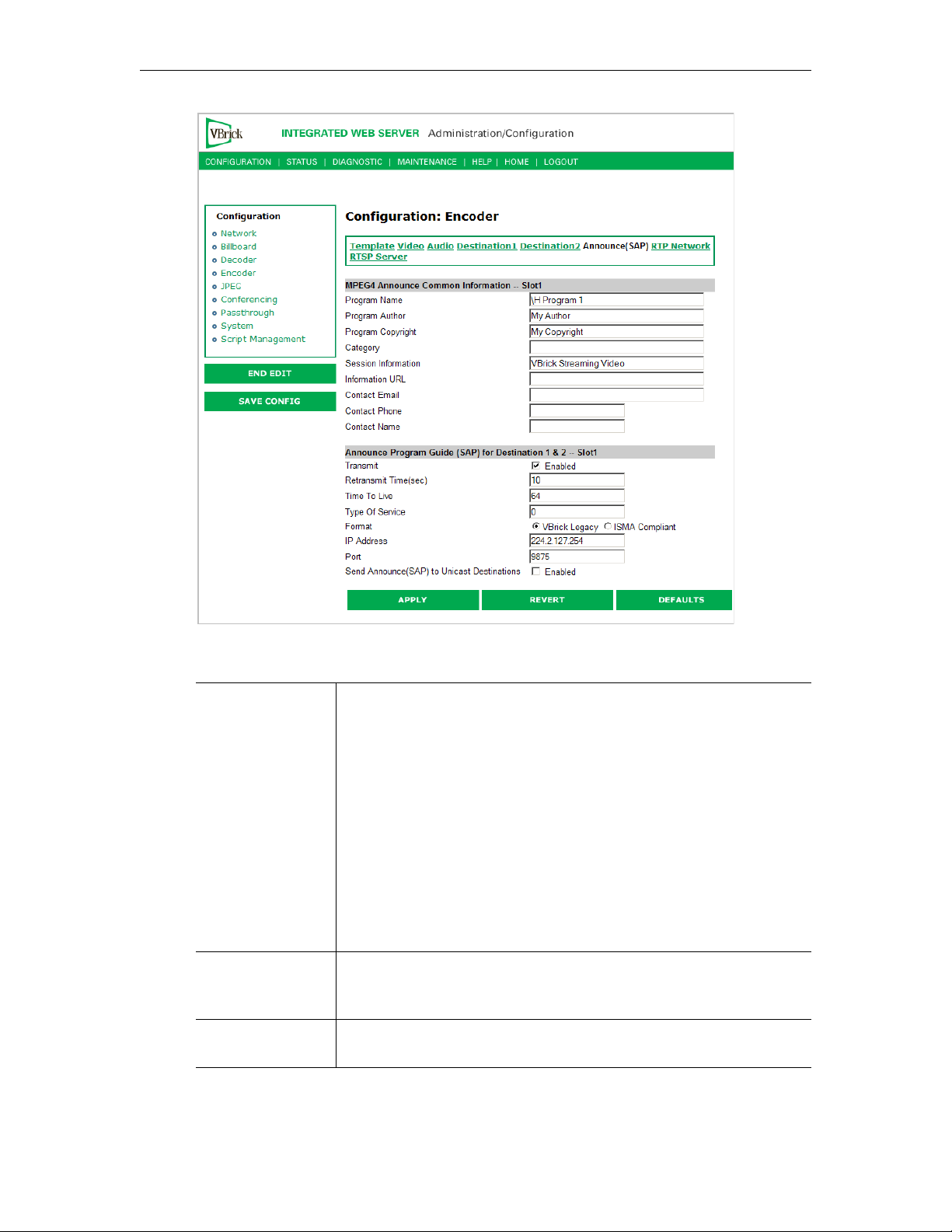
MPEG-4 Configuration
MPEG4 Announce Common Information
Program Name The string providing the name of the stream associated with this
Session Announcement Protocol, or SAP. This SAP text shows up in
the Program Guide for other VBrick products. Default is \H Program
x, (1 or 2, for slot1 or slot2). Both Program Name and Session
Information allow special character strings to be inserted
automatically into these fields. This is true for encoding entries, Slot1
encoders, Slot2 encoders and, when installed, the Hard Drive Pump.
The symbol "\" followed by any other letter is dropped and replaced
by the letter.
• \H or \h – Host Name of Vbrick appliance. When the default
entry is used, the Vbrick is identified by the default Host Name,
and will be identified as such on the network, see the StreamPlayer
software example below.
Program Author A string in the SAP that can be used to identify the author. This
appears in the Windows Media player and others. Default is "My
Author."
Program Copyright A string in the SAP that can be used to identify the copyright
information. Default is "My Copyright."
VBrick MPEG-4 Appliance Admin Guide 35
Page 46

Category An encoder can have a SAP Category string. This string consists of
one or more keywords separated by spaces. Each category keyword
represents a tag associated with the Encoder's video stream. Decoders
can be configured to display in their Program and Conferencing
guides only video streams tagged by specific category keywords or
those containing no keyword. The string(s), used by the Decoder, is
set on the Decoder/Network screen. Characters are printable text and
are case sensitive. The total of all keywords in the string is 36
characters including spaces.
You can also use this field to filter the live streams shown in the ETV
Portal Server by source and client IP address by using the following
IPMask=xxx.xxx.xxx.xxx where xxx.xxx.xxx.xxx represents a
string:
bit mask. (This string is simply another keyword you can use in
addition to those described above.) The Portal Server will parse the
bitmask and send the live stream only to clients with a masked IP
address that matches the masked IP address of the source VBrick. For
example, a stream with a category
with an address of
address
172.22.3.4 but not to a client with an IP Address 172.16.3.4.
172.22.6.67 will be available to a client with an IP
IPMask=255.255.0.0 from a VBrick
There is no admin interface to this feature on the Portal Server; you
can use this filtering in addition to the standard authorization features
provided by the Portal Server.
Session
Information
A string identifying VBrick SAP Session Information that appears on
Program Guide. Default is "VBrick Streaming Video".
Information URL Informational text.
Contact Email Informational text.
Contact Phone Informational text.
Contact Name Informational text.
Announce Program Guide (SAP) for Destination 1 & 2
Transmit Enables or disables SAP transmission. Default = enabled.
Retransmit Time Seconds. 1 – 9999. Default = 10. If SAP Timing is fixed, this is the
time in seconds between SAP transmissions. If SAP Timing is
variable, the actual retransmit time, as per RFC 2974, is reported.
Please refer to Configuration: System > General.
Time to Live The number of hops (between routers) for which an IP packet is valid
on the network.
Type of Service The TOS (Type of Service) can be configured in the IP header to
establish SAP packet priority in the network.
36 © 2009 VBrick Systems, Inc.
Page 47
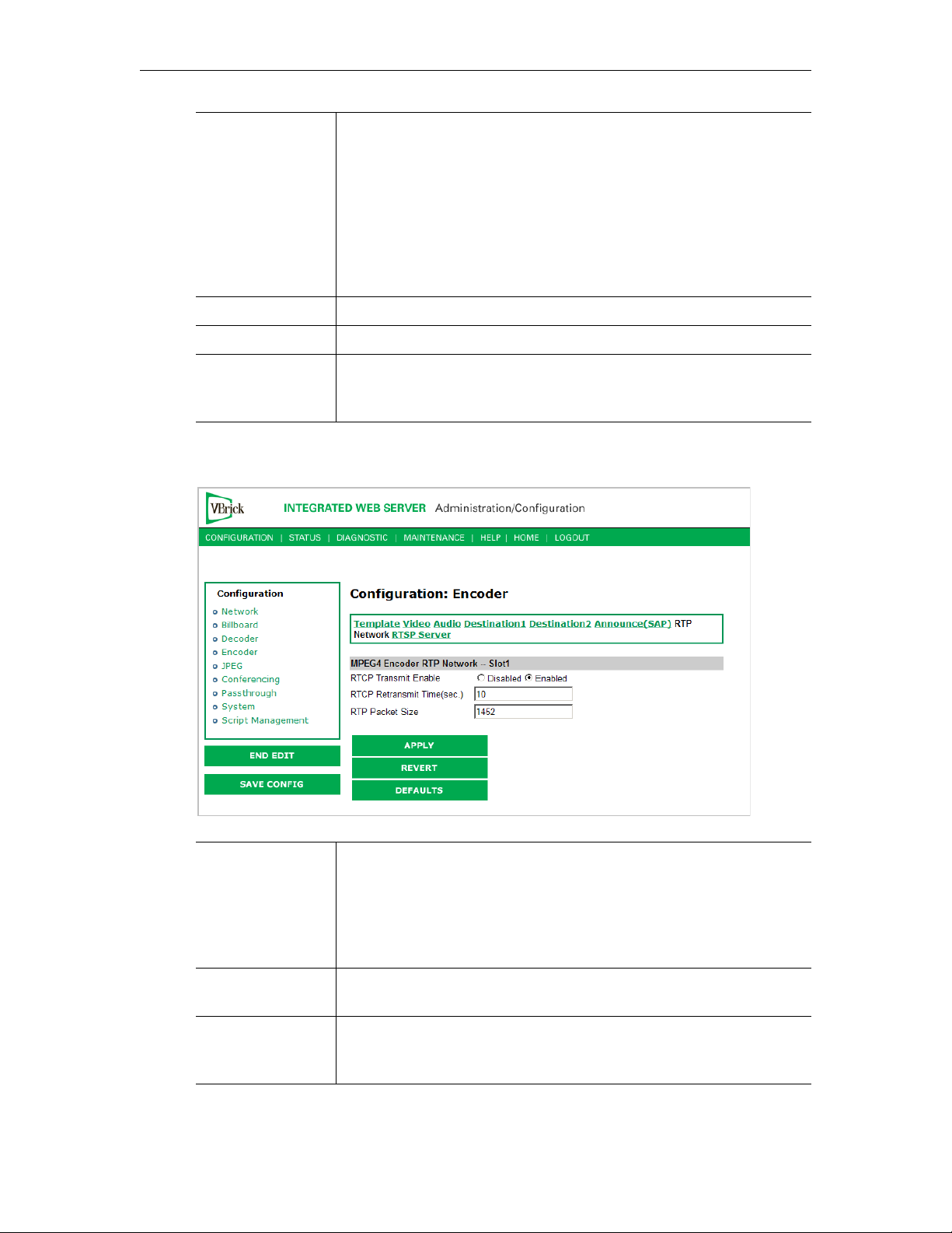
MPEG-4 Configuration
SAP Format Legacy, or ISMA Compliant. Default is Legacy. Note that transmitted
SAPs can be compressed or uncompressed. When set to Legacy, the
SAP message is not compressed and does not contain an initial object
descriptor. This setting is optimized to be compatible with previously
released VBrick SAP transmissions. The ISMA Compliant setting
contains iod and is compressed. SAPs are optimized for compliance
with ISMA standards. When set to ISMA Compliant, the program
guide will not operate correctly on MPEG-1 version 2.5.0 or earlier
and MPEG-2 VBricks version 2.1.0 or earlier.
IP Address The IP address SAP information is sent out to the network.
Port The port SAP information is sent out to the network.
Send Announce
(SAP) to Unicast
Destinations
Forward SAP announcements to all unicast destination addresses
which are configured on the Encoder > Network pages (i.e.
Destination 1 & 2)
Configuration: Encoder > RTP Network
RTCP Transmit
Enable
RTCP Retransmit
Time
RTP Packet Size When choosing an RTP Packet Size, special attention must be paid to
VBrick MPEG-4 Appliance Admin Guide 37
Default = Enable. The RTP standard protocol contains an RTCP, or
Real-time Transport Control element allowing both a VBrick and the
PCs that are receiving video from that VBrick to carry on
communication concerning the quality and stability of the video that is
being sent. Enable allows RTCP sender reports to be sent from the
VBrick.
If the RTCP Transmit is enabled, this setting tells the VBrick how
often (in seconds) to send the reports.
the network capability and topology. The allowed range is 1000 to
1472 bytes per packet, in four byte increments only.
Page 48
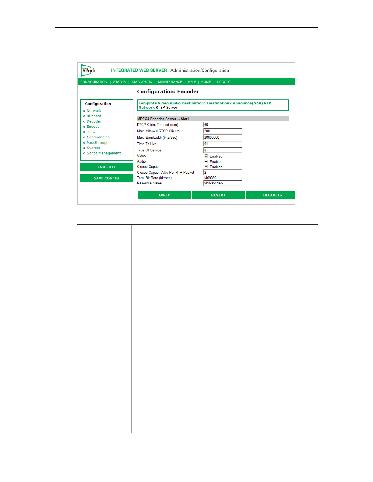
Configuration: Encoder > RTSP Server
Figure 1. Configuration: Encoder > RTSP Server – Part 1
RTCP Client
Timeout
Max. Allowed
RTSP Clients
Max. Bandwidth This is the maximum amount of data that the VBrick will generate at
Time to Live The number of hops (between routers) for which an IP packet is valid
This is the number of seconds that the VBrick will wait before it
decides that an MPEG-4 player that was playing its video or audio is
no longer viewing or listening. Zero means wait forever—no timeout.
This is maximum number of MPEG-4 players that can view video or
audio from the same VBrick at the same time using the RTSP method.
Default for the allowed RTSP clients is 50. This may be increased, but
overall system performance may degrade as this number is increased.
It is recommended that if the Max Allowed Clients is increased, the
configuration should be tested to assure proper operation. Although a
maximum of 200 clients can be configured, only 100 HTTP tunneled
clients are supported because each tunneled client requires 2 TCP
sessions.
any time using RTSP. If the total calculated by adding together the
data in all the video and audio streams that have been started using
RTSP. When this maximum is reached, no additional MPEG-4 players
will be allowed to use the RTSP method. Default for the allowed
RTSP bandwidth is 20MBits/second. This may be increased, but
overall system performance may degrade as this number is increased.
It is recommended that if the max bandwidth is increased, the
configuration should be tested to assure proper operation.
on the network.
Type of Service The TOS (Type of Service) can be configured in the IP header to
establish packet priority in the network.
38 © 2009 VBrick Systems, Inc.
Page 49
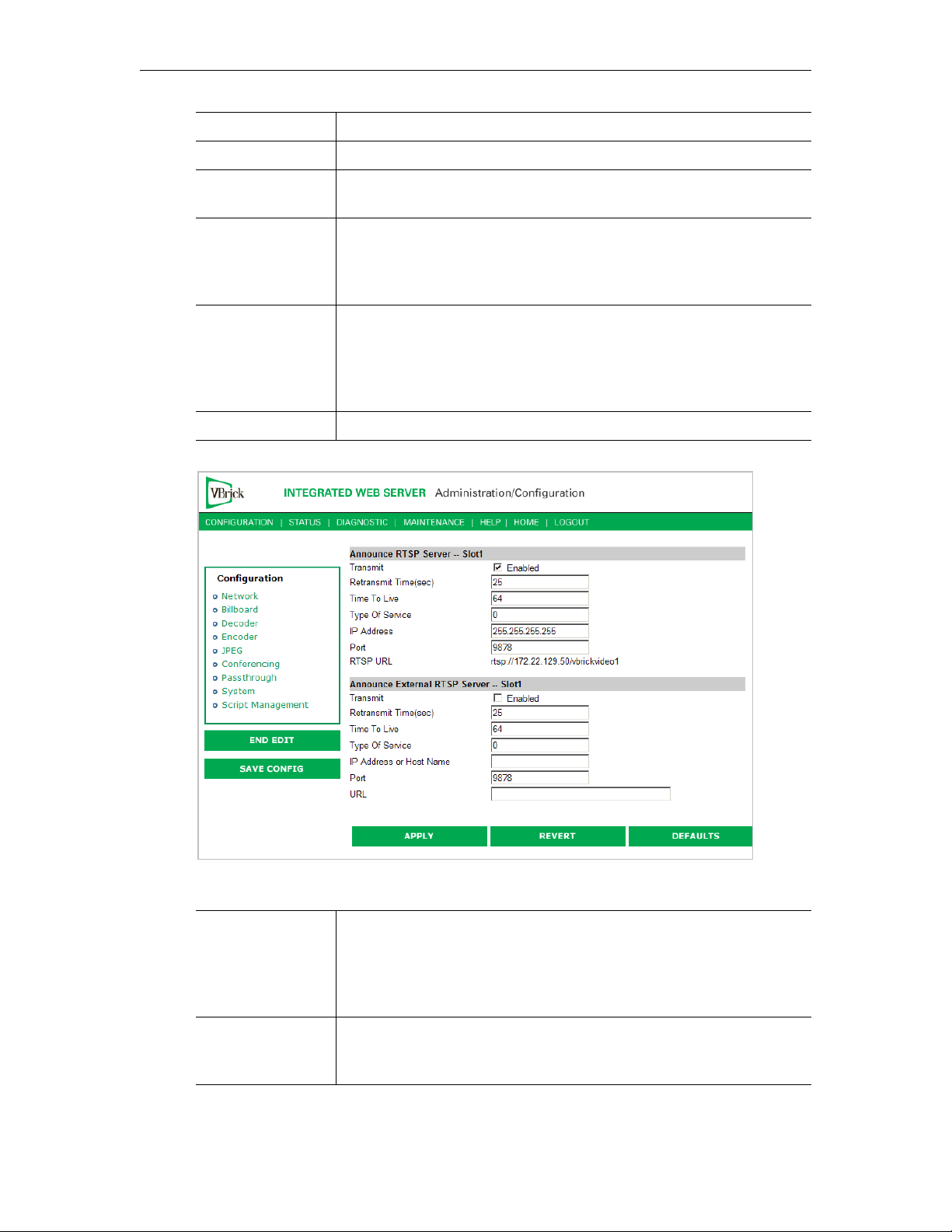
MPEG-4 Configuration
Video If this is disabled no video can be seen using RTSP.
Audio If this is disabled no audio can be heard using RTSP.
Closed Caption If this is disabled no closed captioning can be seen can be heard using
RTSP.
Closed Caption
AUs Per RTP
Packet
This is the number of frames of closed caption frames (access units)
that are placed in each RTP packet. Since each closed caption frame is
small, if multiple Aus are placed in a single RTP packet the bandwidth
efficiency is improved at the cost of additional latency.
Total Bit Rate This is the maximum amount of data the VBrick will generate at any
time using RTSP. It's the total calculated by adding together the data
in all the video/audio/cc streams (including network overhead) that
have been started using RTSP. When this maximum is reached, no
additional MPEG-4 players will be allowed to use the RTSP method.
Resource Name The name used in an RTSP URL to locate a particular stream.
Figure 2. Configuration: Encoder > RTSP Server – Part 2
Announce RTSP
Server
This section is used to announce the RTSP streams to the local
network allowing viewable RTSP SAPs in programs like StreamPlayer
Plus. The unit must be on the same segment of the network or the
Router must be configured to retransmit broadcast in order for the
SAPs to be accessible using the IP Address 255.255.255.255.
Announce
External RTSP
This section is used to announce RTSP streams to a Network device
outside of the broadcast domain.
Server
VBrick MPEG-4 Appliance Admin Guide 39
Page 50
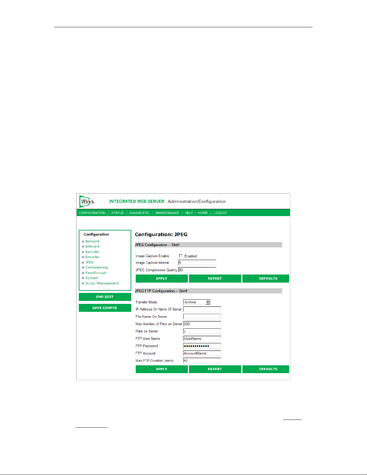
Configuration: JPEG
This windows lets you configure a WM encoder with an attached video source (such as a
camera) in order to take JPEG snapshots at a specified interval. Depending on the
application, the snapshot can be displayed in a web page in realtime or FTPed to a server for
archive storage. Type the following URL in a browser to display the captured image in a web
page. The following URL example contains the folder location of the JPEG file for each
encoder (if there are dual encoders).
Click F5 to refresh image.
http://172.22.123.23/vbs1SnapShot.jpg
vbs1 or vbs2 indicates the slot number of the encoder.
JPEG Configuration
The following fields enable image capture and specify the capture interval and compression
quality. Note that if you change any of these parameters for a live encoder stream, there will
be a momentary (10 seconds or less) loss of video. (For JPEG capture status, see Status:
JPEG Status on page 72.)
40 © 2009 VBrick Systems, Inc.
Page 51

MPEG-4 Configuration
Image Capture Enable Check this box to enable image capture. Default = disabled.
Note that toggling this parameter on or off will reboot the
appliance.
Image Capture Interval 1–600 seconds. Specify the interval at which images are
captured. Default = 5.
JPEG Compression
Quality
0–100. Values over 80 marginally affect image quality and may
impact other system resources. For best results, experiment with
the output and choose the lowest value that provides acceptable
image quality. Default = 80.
JPEG FTP Configuration
The following fields determine how the JPEG images are handled with respect to an FTP
server.
Transfer Mode • Archive – Default mode. Each image is saved as a separate
file up to the value in Max Number of Files on Server. After
the maximum, the files begin to overwrite.
• Single Image – Only one image is saved and overwritten on
the server.
IP Address or Name of
Server
File Name on Server Archive mode – This is the base file name to which incremental
IP address or machine name of FTP server. Default = blank.
numbers are appended. If the base file name is
example, the captured images will be named
VBrick1-2, and so on.
VBrick1- for
VBrick1-1,
Single Image – A .jpg extension will be appended to the base
file name. Default = blank.
Max Number of Files on
Server
1–1000000. The maximum number of files that will be saved on
the FTP server. Default = 200.
Path on Server Folder name where images are saved on FTP server. Default =
root.
FTP User Name FTP user name. Default = UserName.
FTP Password FTP password. Default = UserPassword (hidden).
FTP Account FTP server account login. Default = AccountName.
Max FTP Duration 1–60 seconds. Default = 60. After a server interruption, the
time to wait before closing the connection and trying again.
Configuration: Conferencing
Conferencing is a feature that allows a user to set up a two-way video conference using the IR
Remote Control. This screen provides the configuration of the necessary parameters.
VBrick MPEG-4 Appliance Admin Guide 41
Page 52
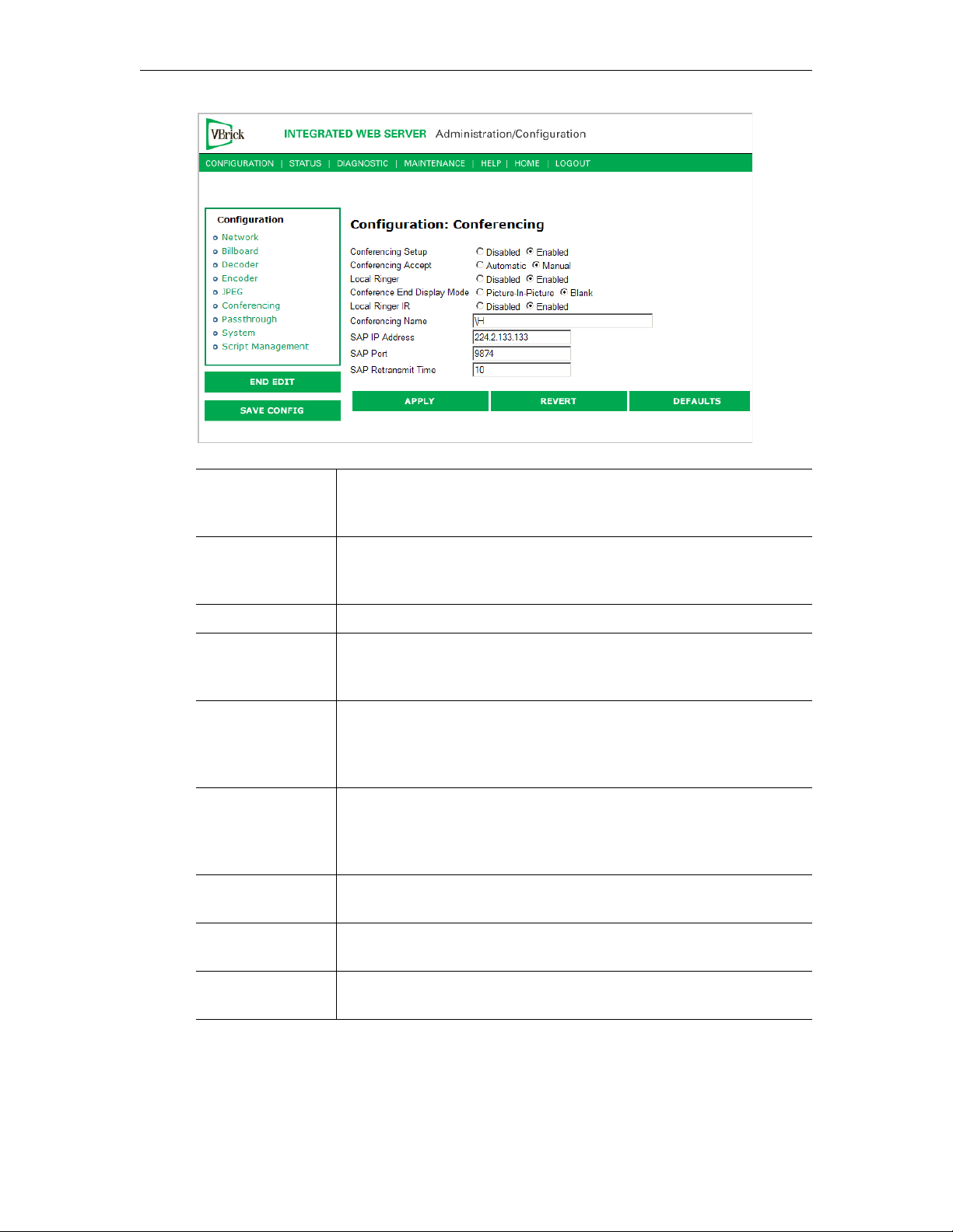
Conferencing
Setup
This option enables/disables the ability of a user to initiate a
conference using an IR remote control unit. Disabled prevents this
VBrick from appearing on the Conference Guide of other VBricks.
Conferencing
Accept
Local Ringer Used to enable/disable the ringer.
Conference End
Display Mode
Local Ringer IR If Enabled, the ringer may be enabled or disabled via the IR remote by
Conferencing
Name
SAP IP Address The SAPs for Conference Call setup are sent to this destination IP
SAP Port The SAPs for Conference Call setup are sent to this destination IP/
SAP Retransmit
Time
Manual, the called party on this VBrick must explicitly accept the
If
call with the IR remote control. If automatic, the call will be accepted
without any action on the part of the called party.
Allows the choice of what is displayed when the conference ends.
Display either Picture-in-Picture (with the local encoder view) or a
Blank Screen.
the user (operator) of this VBrick. If disabled, the local operator
cannot change the state of the ringer. It will remain as set above in
"local ringer".
Used to configure the name of the user (operator) of this VBrick. This
is the name, which will appear on the conference guide screen used to
set up the conference. The default entry is \h or \H, which identifies
the unit by the Host Name of VBrick appliance.
Address.
UDP port.
Allows setting the SAP retransmit time.
Configuration: Passthrough
The TCP/IP network can serve as an intermediary between two VBricks and their serial
ports or between a PC application sending IP packets and a VBrick's serial port. Passthrough
42 © 2009 VBrick Systems, Inc.
Page 53
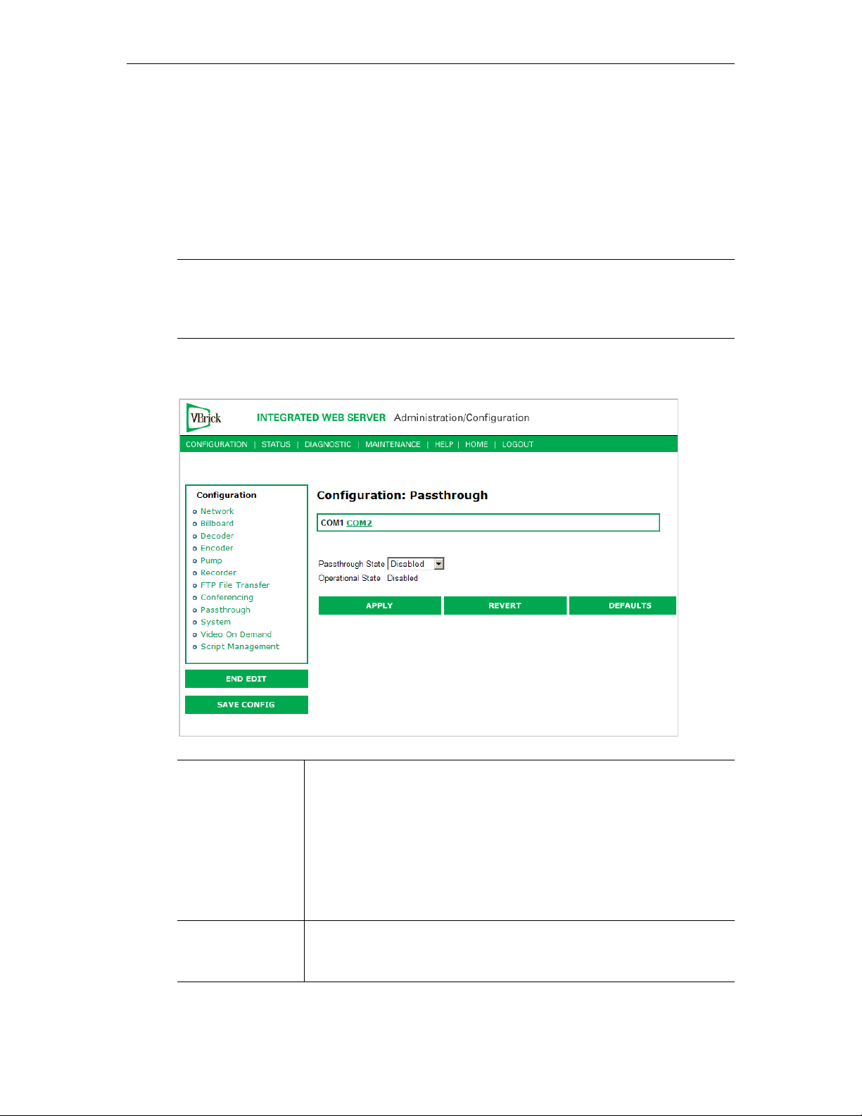
MPEG-4 Configuration
can be configured using addresses on Ethernet or using addresses on ATM. Passthrough on
COM2 is only available on VBricks with a CPLD (programmable logic device) Version
greater than 21. (To check the CPLD , go to Status > System Information > CPLD Version.) If
the IWS screens do not provide a COM1 or COM2 selection at the top of the Passthrough screen, the
VBrick defaults to COM1. This feature supports a wide range of serial applications. See "Serial
Port Passthrough" in the VBrick Appliances Getting Started Guide for more information. Note
that RS-232/422/485 end-to-end control is initiated by enabling or disabling Passthrough.
The Passthrough port for COM1 is 4439; the port for COM2 is 4414.
Note COM2 is a dual purpose interface. At the factory default it can be used as a serial
connection to the VBrick Command Line Interface (CLI) tool for configuration
purposes. When configured for Passthrough, the CLI feature is used for camera
control.
Configuration: Passthrough > COM1
Passthrough State Used to enable/disable Passthrough. Three states are possible:
• Disabled – The VBrick will neither initiate nor respond to
Passthrough setup requests.
• Responder – In this case the VBrick will accept a connection
request (up to 64 connection requests) from another VBrick set as
an Initiator or from a PC camera control application.
• Initiator – In this case it will continuously attempt to automatically
initiate a Passthrough connection to the remote destination.
Operational State Describes the current status of a Passthrough connection, including
error conditions, if any. Refer to the Network Status Section. This will
display "Active" if in Passthrough mode.
VBrick MPEG-4 Appliance Admin Guide 43
Page 54
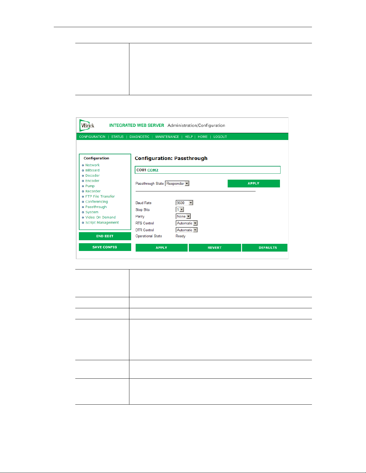
COM Interface
Type
Describes the COM interface connector. (RS422/485 options are
displayed only if main board has a Part Number ending in xxx3. See
Status: User Information > Main Board.)
• RS232 – standard RS-232 serial port connector.
• RS422/485 – RS-422/485 4-wire serial port connector.
• RS422/485 (Terminated) – RS-422/485 terminated.
Passthrough State: Responder
Baud Rate Rate can be set to the following (Default = 9600):
110, 300, 600, 1200, 2400, 3600, 4800, 7200, 9600, 14400, 19200,
28800, 38400, 57600, 115200.
Stop Bits Number of stop bits for Passthrough port (1 or 2).
Parity None, Even, Odd.
RTS Control Force Off, Force On or Automatic. If automatic, the control will be
on when Passthrough is active. DTR and RTS are available for COM2
only for those VBrick models whose last digit is 3 or higher. Under no
conditions are RTS or DTR controls passed through end-to-end. All
control handling is local.
DTR Control Force Off, Force On or Automatic. If automatic, the control will be
On when Passthrough is active. See note above.
Operational State Describes the current status of a Passthrough connection, including
error conditions, if any. Refer to the Network Status Section. This will
display "Active" if in Passthrough mode.
44 © 2009 VBrick Systems, Inc.
Page 55
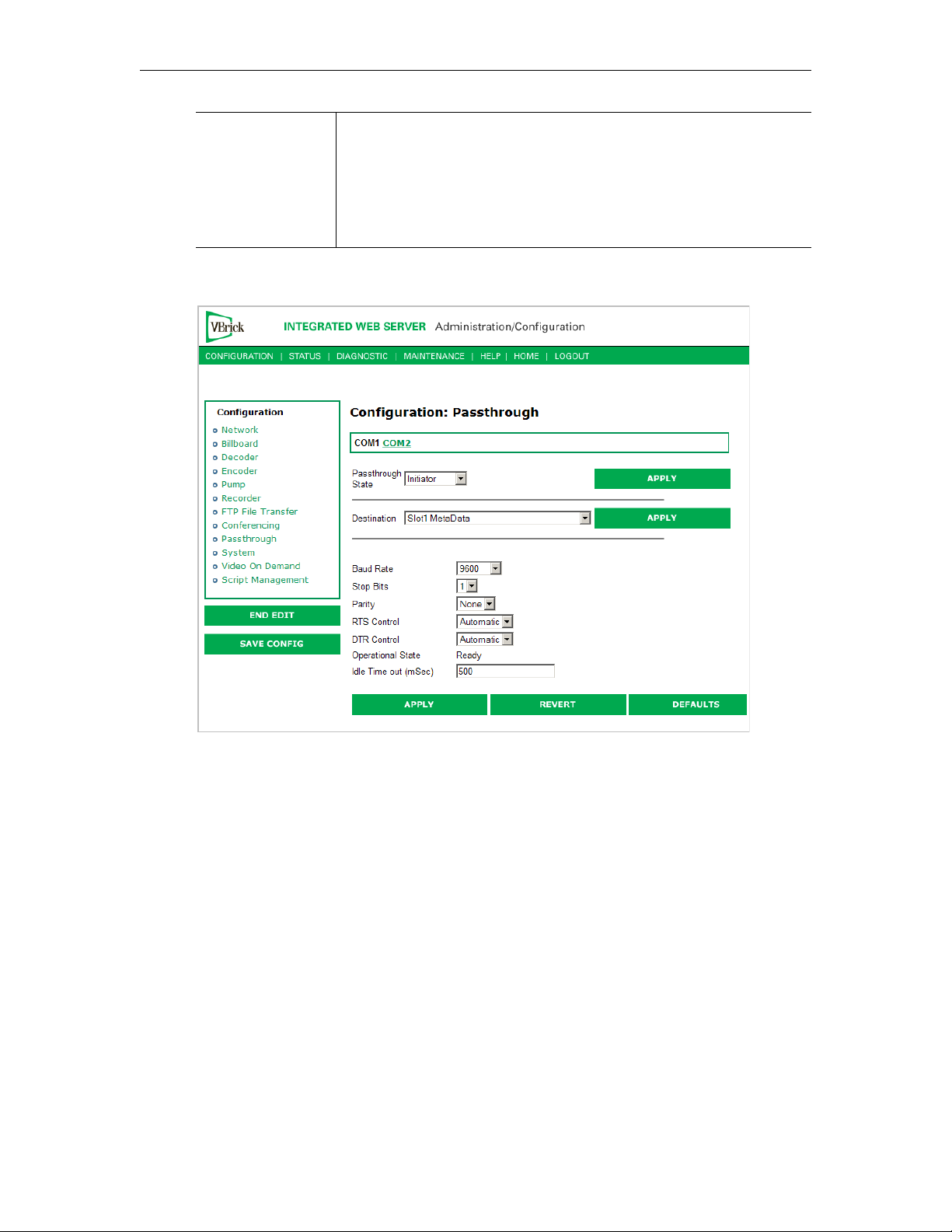
MPEG-4 Configuration
COM Interface
Type
Describes the COM interface connector. (RS422/485 options are
displayed only if main board has a Part Number ending in xxx3. See
Status: User Information > Main Board.)
• RS232 – standard RS-232 serial port connector.
• RS422/485 – RS-422/485 4-wire serial port connector.
• RS422/485 (Terminated) – RS-422/485 terminated.
Passthrough State: Initiator
VBrick MPEG-4 Appliance Admin Guide 45
Page 56

Destination • Remote COM1 using Slot1 Video Endpoint. This means that all
serial data originating at the COM1 port being configured is sent
to the COM1 port of the VBrick identified as the Slot1 video
source (if Slot1 is a decoder) or to the Slot1 video destination
VBrick (if Slot1 is an encoder).
• Remote COM2 using Slot1 Video Endpoint. Slot1 Destination 1
only. Same as above except Initiator destination is COM2.
• Dedicated. When Passthrough State is set as Initiator and the
Destination is Dedicated, the VBrick appliance (whose serial port
is the destination of this COM port) can be configured and
identified using either an IP address or a host name.
• Slot1 MetaData. If Meta Data is enabled on the Encoder > Video
page, the appliance captures incoming data from the serial port and
inserts it into the stream as metadata. In a typical application, a
GPS receiver connected to a VBrick can insert ASCII strings
representing map coordinates into a stream. This information is
saved and sent as metadata with the video. For this feature to
function properly, captions must be enabled in the player (
Captions and Subtitles
). This feature is disabled when the
Play >
appliance is in Edit mode.
The data is inserted when it reaches the maximum number of
characters (250 for MPEG-4) or when the Idle Timeout (see
below) between characters is reached. Note that a four-character
TEXT command and a trailing space are auto-inserted before any
metadata. The Media Player recognizes the TEXT command and
displays the metadata. This feature works for all passthrough port
baud rates but can only accept continuous serial data at rates up to
9600 baud; at higher rates there must be some idle time between
metadata strings.
• Slot2 MetaData. Same as above except the serial port data is
inserted as metadata in the video stream from the Slot2 encoder.
Baud Rate Rate of Passthrough port. Rate can be set to the following (Default =
9600): 110, 300, 600, 1200, 2400, 3600, 4800, 7200, 9600, 14400,
19200, 28800, 38400, 57600, 115200.
Stop Bits Number of stop bits for Passthrough port (1 or 2).
Parity None, Even, Odd.
RTS Control Force Off, Force On or Automatic. If automatic, the control will be
on when Passthrough is active. DTR and RTS are not available for
COM2. Under no conditions are RTS or DTR controls passed
through end-to-end. All control handling is local. DTR and RTS are
not available for COM2.
DTR Control Force Off, Force On or Automatic. If automatic, the control will be
On when Passthrough is active. Not available on COM2. See note
above.
46 © 2009 VBrick Systems, Inc.
Page 57

MPEG-4 Configuration
Operational State Describes the current status of a Passthrough connection, including
error conditions, if any. Refer to the Network Status Section. This will
display
Idle Time out 5–2000 milliseconds. Default = 500. The interval between characters
at which metadata is inserted into the stream.
Active if in Passthrough mode.
COM Interface
Type
Describes the COM interface connector. (RS422/485 options are
displayed only if main board has a Part Number ending in xxx3. See
Status: User Information > Main Board.)
• RS232 – standard RS-232 serial port connector.
• RS422/485 – RS-422/485 4-wire serial port connector.
• RS422/485 (Terminated) – RS-422/485 terminated.
Dedicated Address Mode
When the Passthrough State is set as Initiator and the Destination is Dedicated, the VBrick
appliance can be configured and identified using either an IP address or Host Name.
Configuration: Passthrough > COM2
Passthrough settings for COM2 are a subset of COM1. See Configuration: Passthrough >
COM1 for complete details. As noted, DTR and RTS are not available for COM2. Under no
conditions are RTS or DTR controls passed through end-to-end. All control handling is
local.
Configuration: System
This menu allows the user to set system-related parameters.
Configuration: System > General
VBrick MPEG-4 Appliance Admin Guide 47
Page 58
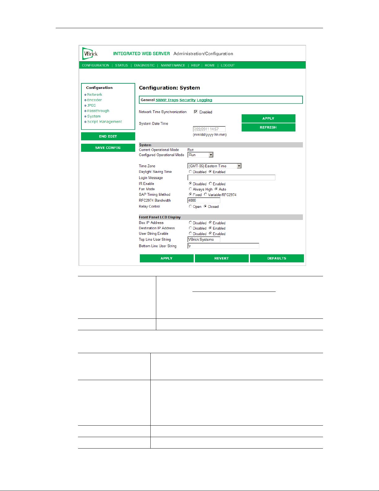
Network Time
Synchronization
System Date Time Set system date and time in mm/dd/yyyy hh:mm format.
Enabled or Disabled. If enabled, the System Date Time field is
inactive. See Network Time Synchronization
host name or IP address of time server. You must set these
parameters before you can enable Network Time Synchronization on
this window.
on page 7 to set
System
Current Operational
Mode
Configured Operational
Mode
Time Zone Select from list: (GMT-12) Eniwetok – (GMT +12) Auckland.
Daylight Savings Time Enabled or Disabled.
48 © 2009 VBrick Systems, Inc.
Indicates the current operational mode of the VBrick. The
following modes are supported. Note: Changing the
Operational Mode automatically reboots the VBrick.
Indicates the configured operational mode of the VBrick. The
following modes are supported:
• Run Mode – Normal operation.
• Diagnostics – User selected mode for running certain
VBrick diagnostics.
Page 59

MPEG-4 Configuration
Login Messsage Enter up to 300 characters of alphanumeric text and special
characters (except quotation marks) that will be displayed on
the IWS login page.
IR Enable Enable or Disable the IR remote control. This is the master
enable and disable for the IR across all functions.
Fan Mode This option allows a user to either force the fan always high or
to automatically cycle on and off based on measured
temperature. Default = Automatic. Note: This option is only
available on VBrick models with a main board assembly whose
last four digits are 0206 or higher.
SAP Timing Method Fixed or Variable - If fixed, the SAP timing will operate as
defined in the encoder, decoder and pump screens with fixed
SAP transmission and timeouts. If variable is selected, the entire
VBrick will use SAP timing as defined in RFC 2974. For most
applications, Fixed Timing should be used.
RFC2974 Bandwidth Allows setting the SAP bandwidth allocation in Bits per second.
This setting is used only when the Timing Method is set to
Var iable.
Relay Control This option allows forcing the relay connection to Open or
Closed. Note: This option is only available on VBricks with a
main board assembly whose last four digits are 0205 or higher.
Front Panel LCD Display
These settings will be displayed for approximately six seconds. After six seconds the LCD
will display the current release, IP address, hostname plus transmit and receive addresses.
Box IP Address Enable or Disable the Box IP Address display on the Front Panel
Display.
Destination IP
Address
Receive IP Address Enable or Disable the Receive IP Address display on the Front Panel
User String
Enabled
Top Line User
String
Bottom Line User
String
Enable or Disable the Destination IP Address display on the Front
Panel Display.
Display.
Enable or Disable the text displayed on the front panel LCD of the
VBrick appliance can be user defined.
The top line can support up to 16 characters. (Characters in excess of
16 will scroll across the display for the bottom line.)
The bottom line up to 40 characters.
Configuration: System > SNMP Traps
SNMP Traps are a subset of the SNMP management component of the VBrick. Use of any
element of the SNMP management system requires use of an SNMP browser or SNMP
manager application (not supplied). The SNMP MIB, which formally defines the SNMP
interface to the VBrick, is contained within the install directory of the VBrick release or from
VBrick MPEG-4 Appliance Admin Guide 49
Page 60
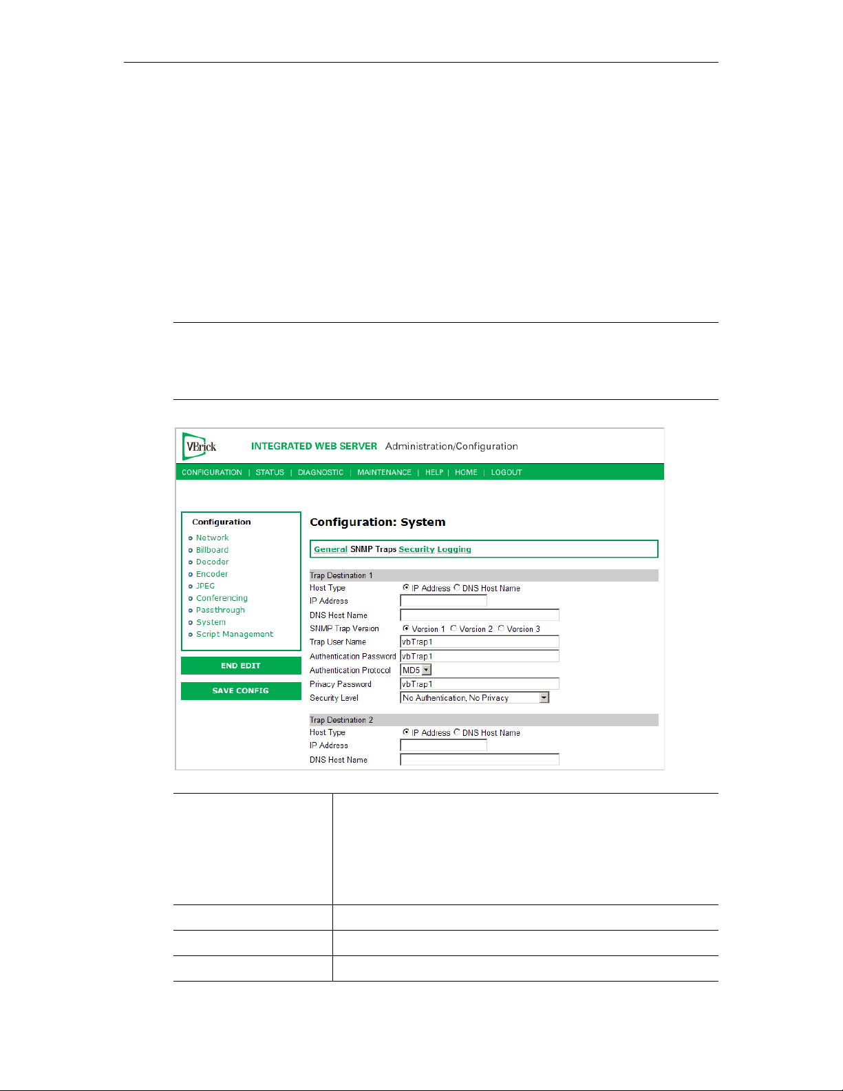
the VBrick. The two MIB files are VBrick_box2.mib and VBrick_reg.mib. The default
installation directory is:
Program Files\VBrick\VB6000\Download\ReleaseVxx_xx_xx
Traps are SNMP base messages used by SNMP elements to report changes in status or alarm
conditions to remote SNMP management entities. Traps are generally used to alert network
administrators of potential equipment problems or other noteworthy events. Two types of
information are conveyed in the trap mechanism: Events and Alarms. Events Traps are sent
every time the monitored event occurs. Events have only one state. Alarms are events having
two states, Active and Clear. When the alarm condition is first detected, an alarm active trap
is emitted. Alarms are considered active until the condition cleared and the alarm clear trap is
emitted.
Note VBrick supports SNMPv3 in addition to SNMP v1/v2. SNMP v3 is a "Secure SNMP
implementation" as defined in Section 11.3 of RFC 3414. It provides initial
configuration in accordance with Appendix A.1 of RFC 3414 and also implements the
Privacy Protocol (DES Encryption) as described in RFC 3414.
Trap Destination
IP Address (1–4)
The IP Addresses of SNMP management stations to which traps
are to be sent. The SNMP management application should be
active on these stations in order to receive a number of SNMP
Traps, which are supported by the VBrick. Enterprise-specific
traps listed in order of trap identification number are shown in
Table 2.
Host Type IP Address or DNS Host Name.
IP Address Complete if Host Type = IP address.
DNS Host Name Complete if Host Type = DNS Host Name.
50 © 2009 VBrick Systems, Inc.
Page 61

MPEG-4 Configuration
SNMP Trap Version Select Version number.
Trap User Name User assigned trap name.
Authentication Password Enter password. Cannot exceed 20 characters. May include any
combination of alphanumeric characters but only the following
special characters:
~ ! # $ ^ * + & [ ] { } | < > See Table 3 on
page 91 for defaults.
Authentication Protocol Select protocol: MD5 or SHA to validate the transaction
between a given host and client
Privacy Password Required. Hides traffic using DES encryption.
Security Level No Authentication, No Privacy (default).
No Privacy.
Authentication and Privacy.
Table 2. Trap Summary Tables
Number Event Description
1 There is loss of video input on slot1 Encoder.
2 The loss of video input on slot1 Encoder failure has cleared.
3 There is loss of video input on slot2 Encoder.
4 The loss of video input on slot2 Encoder failure has cleared.
5 The box has started up in Run mode.
6 The box has started up in Diagnostics mode.
7 The box has started up in Limited Run mode.
8 The box has received a reset request from an administrator.
9 There is a fan failure.
10 The fan failure is recovered.
11 The temperature of the unit is out of range. Will be sent when the unit's internal
temperature becomes too high or too low.
12 The temperature out of range condition has cleared.
13 The 24 volts power supply failed.
14 The 24 volts power supply failure has cleared.
15 The 12 volts power supply failed.
16 The 12 volts power supply failure has cleared.
17 The 5 volts power supply failed.
18 The 5 volts power supply failure has cleared.
19 The 3.3 volts power supply failed.
20 The 3.3 volts power supply failure has cleared.
21 The 2.5 volts power supply failed.
VBrick MPEG-4 Appliance Admin Guide 51
Page 62
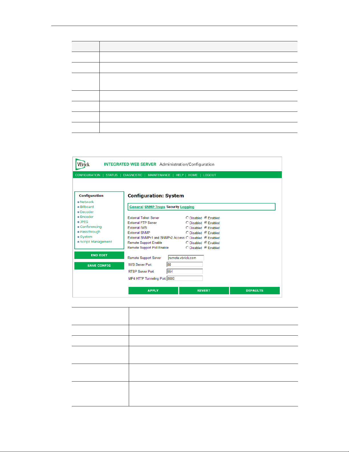
Number Event Description
22 The 2.5 volts power supply failure has cleared.
23 There is a Real Time Clock battery failure.
24 The unit has been configured to transmit and/or receive video streams beyond
its capability.
25 Signifies the overloaded unit is recovered to normal.
26 A component on the main board failed Power On Self Test (POST).
27 The encoder card in Slot1 failed Power On Self Test (POST).
28 The encoder card in Slot1 failed Power On Self Test (POST).
Configuration: System > Security
External Telnet
Server
External FTP Server Enabled, Disabled. Default = Enabled.
External IWS Enabled, Disabled. Default = Enabled.
External SNMP Default = Enabled. Disabled will prevent you from using an
External SNMPv1
and SNMPv2 Access
Remote Support
Enable
52 © 2009 VBrick Systems, Inc.
Enabled, Disabled. Default = Enabled.
external MIB browser to view or write parameters.
Default = Enabled. You can use both SNMP v1/v2, and v3. For
tightest security, set parameter to Disabled and use SNMPv3 only.
Default = Disabled. Check to enable remote support by VBrick
Support Services. Note: Any change to this parameter will reboot the
appliance.
Page 63

MPEG-4 Configuration
Remote Support Poll
Enable
Default = Enabled. The default enables continuous polling through
the firewall. If desired, you can enable polling only when you need
to establish a remote connection. This will not reboot the appliance.
Remote Support
Server
Default =
remote.vbrick.com. Use the default if a DNS server is
defined on the Configuration: Network > Ethernet
page. If a DNS
server is not defined, you must enter an IP Address in this field.
Contact Support Services for details.
IWS Server Port Specifies the listener port for management and HTTP connections.
Default = 80. When the remote IWS user (client) specifies the http
syntax, the port value is generally omitted. Typically port 80 is the
default value used by browsers. As a matter of consistency, the
VBrick default IWS Server Port value is also defaulted to 80. To
access a different HTTP port, the remote IWS client user would
specify the URL as follows:
http://IPaddress:port where
IPaddress = VBrick IP address or hostname, and port. This feature
is often useful for an MPEG-4 system, where HTTP tunneling is
used to traverse firewalls. The IWS server port is moved to another
location (ex. 8080) and the HTTP Tunneling port is set to 80.
RTSP Server Port Specifies the listener port for RTSP connections. Default = 554.
MP4 HTTP
Tunneling Port
Specifies the port used for HTTP Tunneling. This feature allows
RTSP connections to be sent as TCP rather than UDP, it is
recommended to use port 80 when doing this. Default = 8080.
Note that the MPEG4 encoder supports tunneling, as do
StreamPlayer and Quicktime. However the MPEG-4 decoder does
not support HTTP tunneling.
Improving Security
You can improve security by (1) blocking unauthorized attempts to login and access a device
and (2) by reducing exposure to malicious software attacks. The most common vulnerability
is related to user accounts and passwords. After a successful installation, you should
immediately change the default passwords. Many attacks come from within an organization
and this helps to minimize the risk. The IWS login is generally secure since it utilizes
encryption techniques to hide usernames and passwords from network spyware.
Malicious software covertly attaches itself to unsuspecting devices. These programs are
generally designed to compromise personal information or to create system havoc. Since the
VBrick appliance uses an industrial-grade operating system, it is less susceptible to malicious
software and unlikely to be a target of programs designed to attack PC-based systems like
Microsoft, Linux, and others. However, you can still take additional steps to minimize risk.
VBrick tries to make installation as simple and quick installation and many features are
automatically enabled by default even though you may not need them. You can selectively
disable unneeded features to reduce vulnerability. Another common problem is Denial of
Service (DoS) attacks. A DoS sends floods of packets to an unsuspecting remote system in an
attempt to disrupt or stop normal operation. These unsuspecting remote systems are typically
discovered using ICMP or ping. It is standard industry practice to block all ICMP and ping
requests from off-net foreign hosts. This is typically done in a centralized location using
router/firewall technology which is more successful and cost effective than resolving the
issue at each host.
VBrick MPEG-4 Appliance Admin Guide 53
Page 64
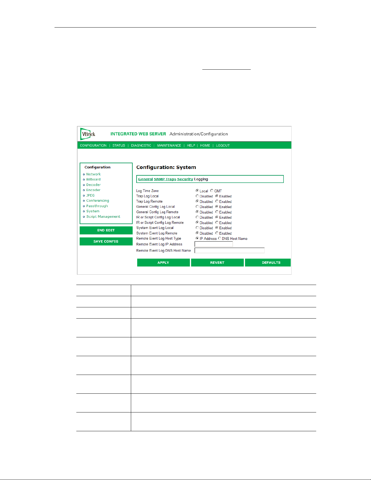
Configuration: System > Logging
Certain log events are captured and can be viewed locally. This local log is saved in volatile
memory and hold the most recent 20 entries. See Status: System Log on page 75 for examples
of log information. To save log information indefinitely, it is recommended that remote
logging be utilized. Remote servers generally offer ample storage and offer the additional
benefit of collecting log information from several VBricks simultaneously. When logging
externally, specify either the IP address or hostname a server that is configured to receive
SNMP traps on port 162 into the Remote Event Log IP Address or Remove Event Log DNS
Host Name fields.
Log Time Zone Specifies the time zone (Local or GMT) that is used for logged events.
Trap Log Local If Enabled, displays trap events in the local log.
Trap Log Remote If Enabled, sends trap event notices to a remote host.
General Config
Log Local
General Config
Log Remote
IR or Script Config
Log Local
IR or Script Config
Log Remote
Remote Event Log
Host Type
Remote Event Log
IP Address
54 © 2009 VBrick Systems, Inc.
If Enabled, displays configuration changes in the local log.
If Enabled, sends configuration change notices to a remote host.
If Enabled, displays IR or script-generated configuration changes in
the local log.
If Enabled, sends IR or script-generated configuration changes to a
remote host.
Identify remote event log server by host name.
Identify remote event log server by IP address.
Page 65

MPEG-4 Configuration
Remote Event Log
DNS Host Name
Host name of remote event log server.
Configuration: Script Management
Configuration: Script Management > Event Triggering
You can create and run scripts to activate certain functions on a VBrick appliance. There are
three ways to run scripts on an appliance. (1) You can run scripts for test purposes using the
Run Script button in IWS; (2) you can use the IR Remote Control; and (3) you can use an
external event trigger (see "Event Triggering" in the VBrick Appliance Getting Started Guide).
The VBrick appliance can be set up to use serial (COM1) Pins 7 and 8, or 0 through 9 on the
IR Remote as input events to trigger the VBrick to run scripts. The script files execute certain
commands using VBrick SDK parameters to activate certain functions within the VBrick
appliance. There are a total of four possible input events (COM1 Pin8 Low, COM1 Pin8
High, COM1 Pin7 Low, COM1 Pin7 High) and ten possible input events using the IR
Remote (each has one associated script file).
VBrick SDK parameters are explained in detail in the VBrick SDK User Guide. The VBrick
SDK is available for customers who wish to build custom applications to control VBrick
appliances. It also explains how to configure and control VBrick appliances via command line
scripts. For more information about the VBrick SDK, contact your certified VBrick reseller
or VBrick Support Services
www.vbrick.com/products/purchase.asp.
. To purchase the SDK directly from VBrick, go to:
Note You cannot execute a script either with the IR Remote Control or using an event
trigger if IWS is currently running in
IWS, it automatically exits
Edit mode and terminates the active editing session.
Edit mode. If you run a script directly from
Run Scripts Using IWS
You can run scripts that were previously created with the VBrick SDK using the Run Script
button in IWS. This button is only available in Edit mode and is basically used for test
purposes. See Sample Script below.
VBrick MPEG-4 Appliance Admin Guide 55
Page 66
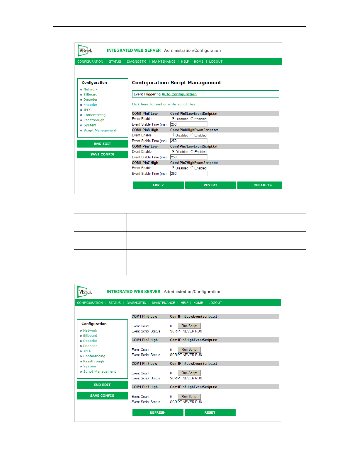
Figure 3. Script Management – Part 1
Click here to read
or write script files
Login to the VBrick via FTP and manage script files. Requires a valid
user name and password.
Event Enable Allows the user to Enable/Disable Event Triggering for each input
event.
Event Stable Time Allows the user to enter the amount of time in milliseconds that each
input event has to be stable at the active level before the script will be
executed.
56 © 2009 VBrick Systems, Inc.
Page 67

MPEG-4 Configuration
Figure 4. Script Management – Part 2
Event Count Displays the number of times each input event has occurred.
Event Script Status Displays current status information for each event script.
Run Script These buttons allow the user to run each script without needing the
input event. Use this method to test the script.
IR Remote Scripts are enabled by simply placing a file named
number from
naming the following script
0–9) in the script directory of the unit. For example
ir0Script.txt will enable the 0 on the IR
irNScript.txt (where N is a
remote to trigger the unit to run the script.
Run Scripts Using the IR Remote Control
IR Remote Control scripts are enabled by simply placing a file named irNScript.txt (where
N is a number from 0–9) in the script directory of the unit. For example naming the following
script
ir0Script.txt will enable the 0 on the IR remote to trigger the unit to run the script.
Run Scripts Using Event Triggers
The event triggering feature lets you use an external switch or power source to control the
functions of the VBrick appliance. See "Event Triggering" in the VBrick Appliance Getting
Started Guide for detailed examples.
Sample Script
vbrickSlot2EncoderNetworkTransmitEnable = 2 // set enable slot 2 encoder transmit
vbrickSlot2EncoderNetworkApplySet = 2 // apply above encoder network set
* // end of a group
vbrickHDRecorderControlMode = 1 // set recorder to user controlled mode
vbrickHDRecorderControlIrEnable = 1 // disable recorder ir control
vbrickHDRecorderControlName = event1record.mpg // set recorder file name
vbrickHDRecorderControlDuration.value = 30 // set recorder duration to 30 seconds
vbrickHDRecorderControlBatchEnable = 1 // set recorder batch to disabled
vbrickHDRecorderControlApplySet = 2 // apply above recorder control sets
* // end of a group
vbrickHDRecorderControlFtpEnable = 1 // disable auto ftp after record
vbrickHDRecorderControlApplySet = 2 // apply above recorder control set
vbrickHDRecorderNetworkReceiveType = 1 // set recorder receive type to ip address
vbrickHDRecorderNetworkReceiveIpAddr = 239.22.129.3 // set recorder receive ip address
vbrickHDRecorderNetworkReceivePort = 4443 // set recorder receive port
vbrickHDRecorderNetworkApplySet = 2 // apply above recorder network sets
* // end of a group
vbrickHDRecorderOperationStart = 2 // start recording
* // end of a group
wait = 5000 // wait for 5000 milliseconds
* // end of a group
vbrickSlot1EncoderNetworkTransmitEnable = 2 // set enable slot 1 encoder transmit
vbrickSlot1EncoderNetworkApplySet = 2 // apply above encoder network set
* // end of a group
VBrick MPEG-4 Appliance Admin Guide 57
Page 68
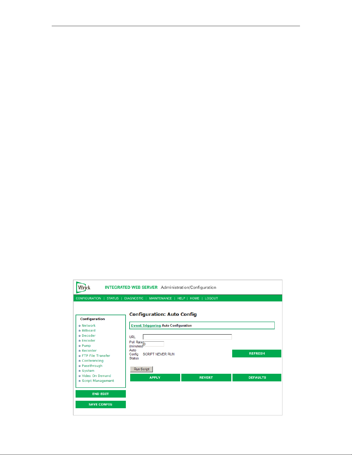
Scripting Notes
• * denotes end of group.
• Each group can have a maximum of six sets.
• Each group must have apply sets for all normal sets.
• Wait state will be alone in a group.
• There is no clear command.
• Script commands must start in column 1.
• There is no chaining of scripts.
• Comments will start with / and can be a line or the end of a command.
• All scripts are executed in a strictly serial manner by a single task.
• While executing a script it is possible to miss a double change of any event.
Configuration: Script Management > Auto Configuration
Auto Config lets you perform an auto-configuration via a URL script file. It is typically used
for remote configuration and troubleshooting or to configure VBrick appliances that are
behind a firewall. To configure a parameter on an appliance (or more likely a set of
parameters) you simply point the URL to a server with an .xml configuration file. This is
useful, for example, to change a reflector URL, set the audio and video rates, etc. when the
VBrick appliances are behind a firewall and cannot be accessed remotely.
The VBrick reads the URL field (e.g.
executes the script depending on the
www.myserver.com/config.xml) via HTTP protocol and
EXECUTE tag. If a VBEXECUTEFORCE tag is present in the
.xml file (see example below), the script runs every time at the poll interval even if it has not
changed. If a VBEXECUTEIFDIF tag is present the script runs only if it is different from the last
executed file. One of these tags is required.
If the VBrick is in
Edit mode, the script file will not run until the edit session is ended. The
auto config script will run before any waiting IR scripts or external event scripts. In Edit mode,
you can press Run Script to execute the script on demand. After a reboot, the VBrick checks
for a script URL and will run the script immediately, regardless of the
VBEXECUTE tag value.
58 © 2009 VBrick Systems, Inc.
Page 69

MPEG-4 Configuration
URL Valid path to a URL script file, for example: www.myserver.com/
config.xml
. Default = blank.
Poll Rate The rate at which the appliance checks the config file. 0–1440 minutes
(default = 0).
Auto Config Status Shows auto config status including when the script was last run, URL
connection errors, etc. Press Refresh to update.
Run Script Edit mode only. Run the script now.
Sample Script
The auto config script file (config.xml) is an .xml file with the following syntax. It can set any
VBrick parameters and force an "apply" as needed. This example shows how to set various
recorder parameters. Note that a
<XML Header>
<?VBEXECUTEFORCE?>
<VBRICK>
vbrickHDRecorderControlMode = 1
vbrickHDRecorderControlIrEnable = 1
vbrickHDRecorderControlName = event1record.mpg
vbrickHDRecorderControlDuration.value = 30
vbrickHDRecorderControlBatchEnable = 1
vbrickHDRecorderControlApplySet = 2
</VBRICK>
or <?VBEXECUTEIFDIF?>
VBEXECUTE task is required.
Note Text files created on Windows machines have different line endings than those created
on Unix or Linux machines. Windows machines use a carriage return and line feed
\r\n) whereas Unix machines use line feed (\n) only. A script created on a Windows
(
machine must be modified in order to work properly on a Unix machine.
VBrick MPEG-4 Appliance Admin Guide 59
Page 70

60 © 2009 VBrick Systems, Inc.
Page 71

System Status
The Status menu lets you view information and status relative to the VBrick appliance. The
Refresh button allows the user to update the statistics to display the most current values. A
Reset button is also present on some screens. This lets you reset all statistic counters.
Topics in this chapter
Status: System Information . . . . . . . . . . . . . . . . . . . . . . . . . . . . . . . . . . . . . . . . . . . . . . . . . . 61
Status: Network Status. . . . . . . . . . . . . . . . . . . . . . . . . . . . . . . . . . . . . . . . . . . . . . . . . . . . . .63
Status: Decoder Status . . . . . . . . . . . . . . . . . . . . . . . . . . . . . . . . . . . . . . . . . . . . . . . . . . . . . .66
Status: Encoder Status . . . . . . . . . . . . . . . . . . . . . . . . . . . . . . . . . . . . . . . . . . . . . . . . . . . . . .70
Status: JPEG Status . . . . . . . . . . . . . . . . . . . . . . . . . . . . . . . . . . . . . . . . . . . . . . . . . . . . . . . . 72
Status: RTSP Server Status. . . . . . . . . . . . . . . . . . . . . . . . . . . . . . . . . . . . . . . . . . . . . . . . . . . 73
Status: System Log . . . . . . . . . . . . . . . . . . . . . . . . . . . . . . . . . . . . . . . . . . . . . . . . . . . . . . . . . 75
Status: User Information . . . . . . . . . . . . . . . . . . . . . . . . . . . . . . . . . . . . . . . . . . . . . . . . . . . . 77
Chapter 3
Status: System Information
This menu allows the user to view vital system information. Some of this information
represents parameters describing the VBrick as shipped; others provide information
concerning the current VBrick operation.
VBrick MPEG-4 Appliance Admin Guide 61
Page 72
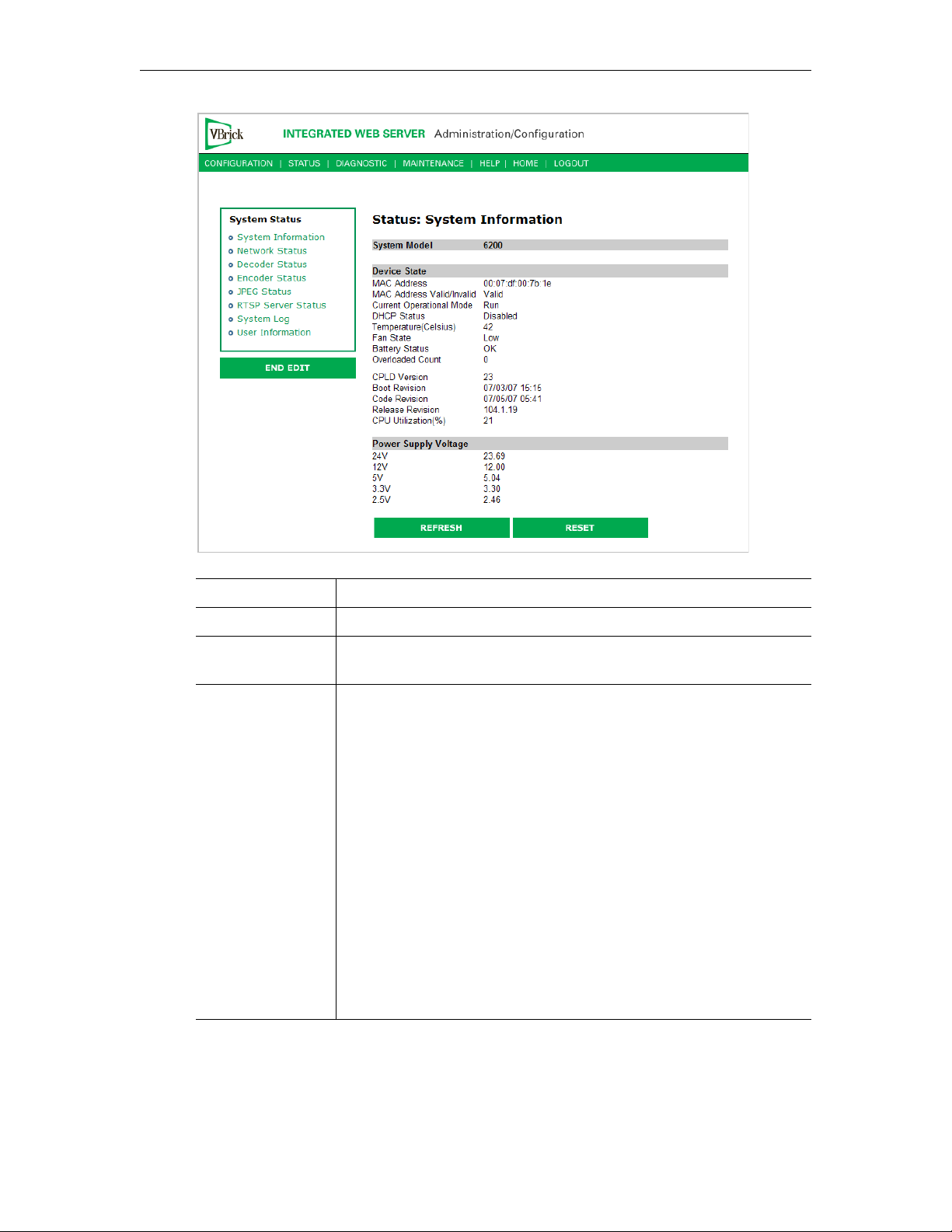
System Model Displays the model number of the appliance.
MAC Address Displays the MAC (Media Access Control) address of the appliance.
MAC Address
Valid
Current
Operational Mode
Verifies that the MAC address is valid.
Indicates the current operational mode of the VBrick. The following
modes are supported:
• Run Mode – Normal operation.
• Diagnostics – User selected mode for running certain VBrick
diagnostics.
• Limited Run Mode – Limited operational mode (not selectable).
Normally occurs if a hardware problem exists within the VBrick
but it can still partially operate.
• Overloaded Mode – Limited operational mode (not selectable).
This mode occurs when the VBrick is configured to handle more
video than its operational capacity. It automatically reconfigures
itself to allow continued remote and local management. If this
occurs, the VBrick needs to be reconfigured to reduce the number
of streams and/or data rates. Under this condition, the appliance
temporarily reduces video traffic in order to maintain IWS
functionality.
62 © 2009 VBrick Systems, Inc.
Page 73

System Status
DHCP Status Dynamic Host Configuration Protocol – Ethernet models only.
Enabled/Disabled. Possible DHCP Status values:
• Disabled
• Succeeded
•Failed
• Succeeded without Subnet Value – No subnet value given;
generated from IP address.
• Succeeded with Invalid Subnet Value – Invalid subnet value given;
generated from IP address.
• Failed over Backplane – Device number invalid in backplane.
• Failed, Invalid Device Unit – Network interface device number
invalid.
• Failed Invalid Cookie – Network interface inoperable.
• Failed, Bind Failed – DHCP server not available or appliance not
connected to network.
• Failed, Out of Memory – Appliance is out of memory. Indicates a
severe condition.
• Failed, Parameter Get Failed – Couldn't retrieve a DHCP
parameter needed/requested.
• Failed, Invalid Boot File – Invalid boot file specified. Indicates a
severe condition.
• Failed, Invalid Retrieved IP address assigned by the server is not a
valid unicast address.
Temperature Displays the temperature of the appliance (Celsius).
Fan State Displays the state of the fan as
Battery Status OK or Failed.
Overloaded Count Provides a count of the number of times the box has entered the
Overloaded state.
CPLD version Displays the Main Board programmable device version number.
Boot Revision Displays the date of the last boot revision.
Code Revision Displays the date of the last code revision.
Release Revision Displays the release version number.
CPU Utilization% The percentage of the Central Processor in use at this time.
Power Supply
Voltag e
Displays the measured voltages present and provided to the VBrick
(24V, 12V, 5V, 3.3V 2.5V). The tolerance range for 24V is minimum
18V to maximum 25V. The range for all other voltages is plus or
minus 5%.
Status: Network Status
Status: Network Status > Codec
Not Operational, High or Low.
This menu allows the user to view various network-level conditions.
VBrick MPEG-4 Appliance Admin Guide 63
Page 74
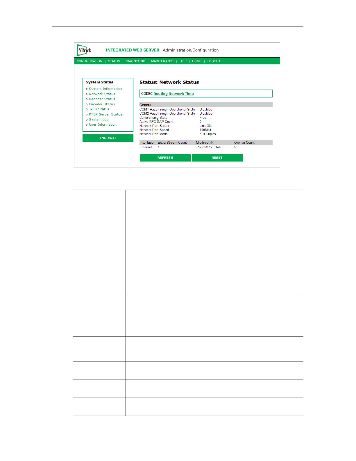
General
COM1/COM2
Passthrough
Operational State
The current operational state of COM1/COM2 serial Passthrough
port. There will be a conflict if the slot selected through the
Passthrough Destination parameter has neither an encoder nor a
decoder present; or has an encoder with a multicast destination; or has
an encoder with no configured destination. The possible values are:
• Disabled
• Enabled Active
• Enabled Conflict No Enc Or Dest
• Enabled Conflict Enc Multi Dest
• Enabled Conflict Enc No Dest
• Enabled Internal Error
• Enabled Rejected
• No Dedicated IP Addr
Conferencing State This setting indicates the unicast call state of the encoder.
• Free – Available for a conference.
• Busy – The VBrick is currently engaged in a conference.
• Disabled – The conference feature has been disabled.
• Unknown – The VBrick is in a transition state.
Active RFC-SAP
Count
This is the number of SAP sessions the appliance is currently listening
to for the purpose of RFC 2974-compliant SAP timing. This field
displays values when SAP timing is configured for RFC 2974 mode.
Network Port
The status of the Ethernet network interface:
Link OK or No Link.
Status
Network Port
Speed
Network Speed
Mode
64 © 2009 VBrick Systems, Inc.
The speed of transmission for the Ethernet network interface:
or
100Mbit.
The mode of transmission for the Ethernet network interface:
or Half Duplex.
Duplex
10Mbit
Full
Page 75
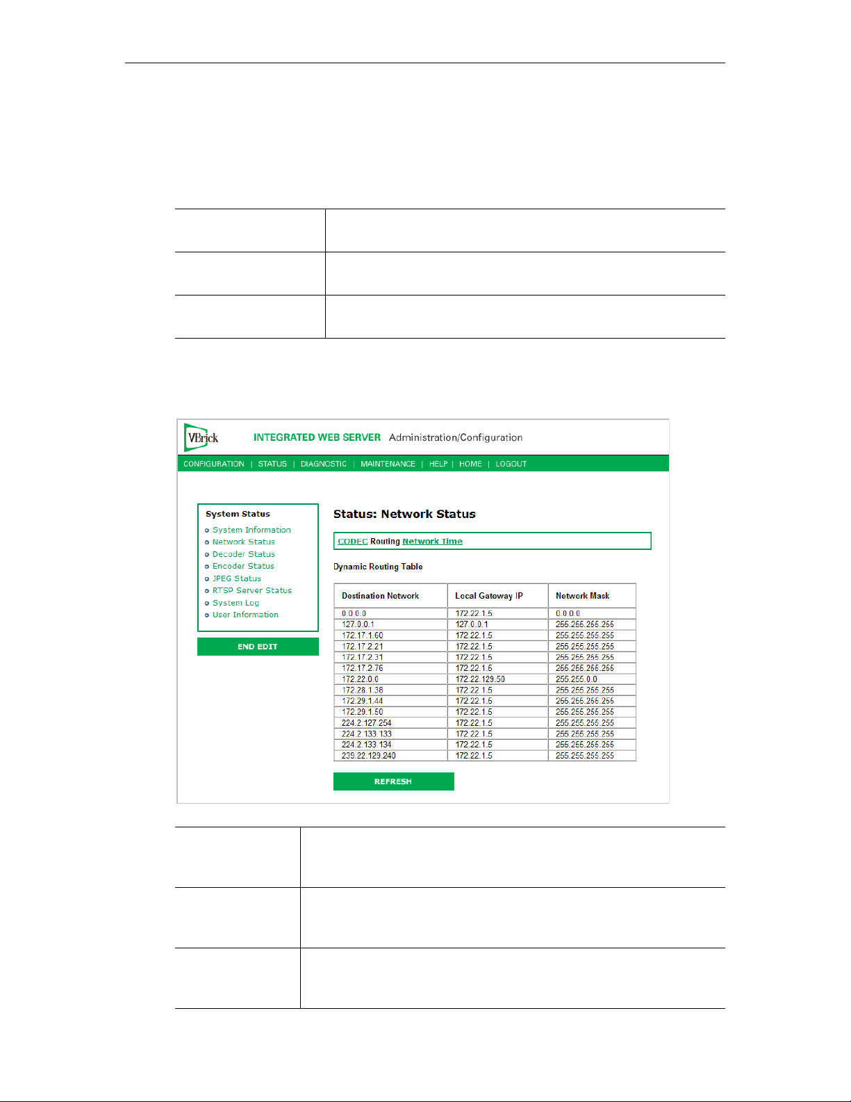
System Status
Interface
This section reports the existence of any undesired (and unrequested) video streams being
received by the VBrick. Unrequested streams greater than 1.5 Mbps are automatically flagged
and dropped. The reporting is made for each IP interface individually. On Ethernet models,
only one interface exists.
Extra Stream Count Number of unexpected video streams being received on this
interface.
Misdirect IP Address The IP Address of the appliance transmitting one of the extra
video streams received on this interface.
Orphan Count Orphans are packet fragments received that do not have
corresponding head PDUs.
Status: Network Status > Routing
This display screen allows the user to view the Internal Routing Tables.
Destination
Network
Local Gateway IP Defines the intermediary network device (or entity) which is
Network Mask Defines the destination network's address scope specified in the first
VBrick MPEG-4 Appliance Admin Guide 65
Defines a target network (or device) that can be contacted via the
system. A value of 0.0.0.0, is used to indicate a default routing entry.
The 127.0.0.1 is always present and identifies the loopback route.
responsible for IP forwarding to the given destination network
specified in the first column.
column. Mask bits which are zeros, identify the host portion of the
address space. Bits that are "ones" identify the network portion.
Page 76
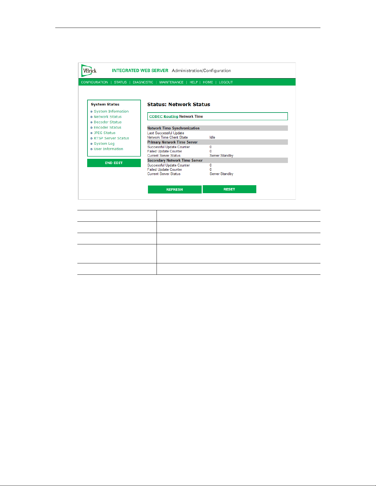
Status: Network Status > Network Time
Last Successful Update The last time the appliance successfully acquired the time.
Network Time Client State Status of client.
Successful Update Counter The number of times the time was reset from the server.
Failed Update Counter The number of times the appliance failed to read the time
Current Server Status Status of server.
Status: Decoder Status
This window shows the general status of decoder's connection mode, video and audio.
Status: Decoder Status > General
Use this status window to verify your connection between an encoder and a decoder.
from the server.
66 © 2009 VBrick Systems, Inc.
Page 77
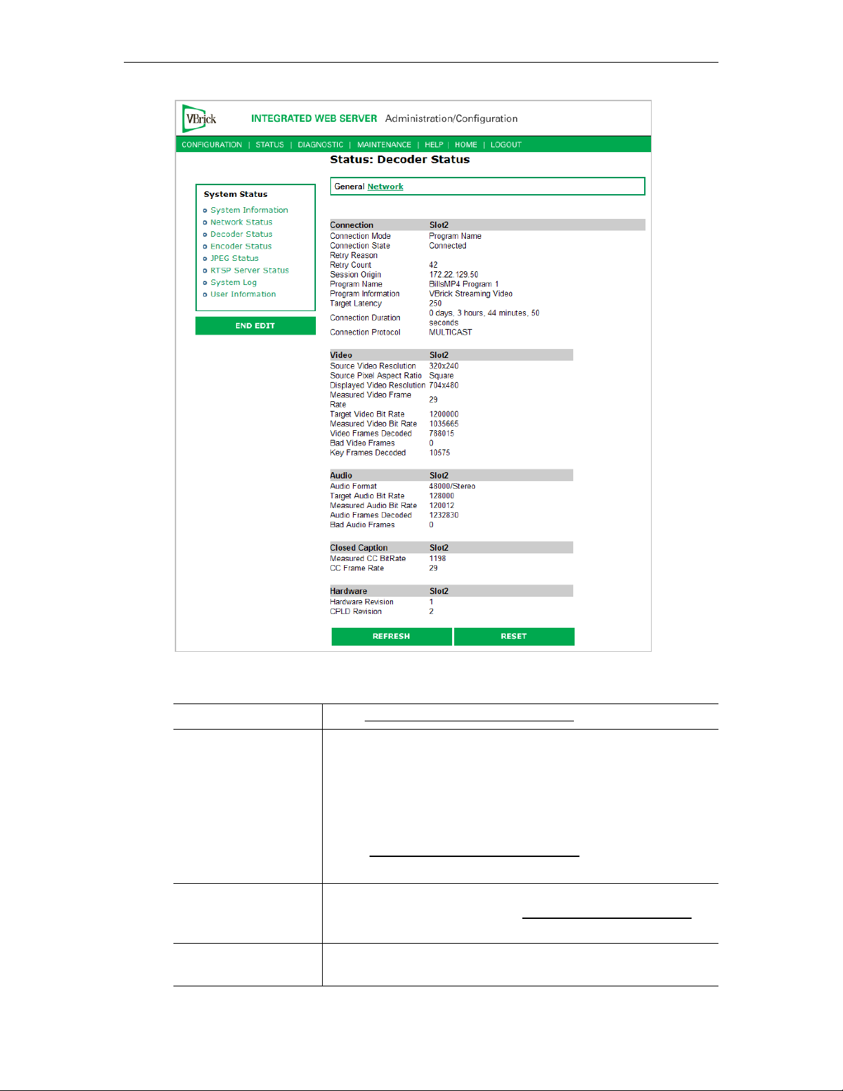
System Status
Connection
Connection Mode Set in Configuration: Decoder > Network.
Connection State Indicates the state of the connection to the encoder:
• Connected – The decoder is connected to the encoder and is
receiving packets associated with the program.
• Connecting – The decoder is in the process of connecting to
the encoder.
• Disabled – The decoder is disabled.
the Configuration: Decoder > Network page.
• Stopped – A user has stopped or paused the decoder.
Retry Reason If the decoder is not connected, a connection to the encoder was
not established or has failed. See Status: System Log > Config
page 75 for more details.
Retry Count Total attempted retrys. For a failed connection, the decoder will
automatically attempt a reconnect every five seconds.
VBrick MPEG-4 Appliance Admin Guide 67
Receive is not enabled on
on
Page 78

Session Origin Derived from SDP file. The IP address, VBrick Host Name, or
DNS name of the encoder. If the
Address or Hostname
, the slot number is appended.
Connection Mode is VBrick IP
Program Name Derived from SDP file. The program name for the stream this
decoder is receiving.
Program Information The program information in the SDP file for the stream this
decoder is receiving. Default is "VBrick Streaming Video."
Target Latency Defines the decoder latency which the software is attempting to
maintain. A primary factor in determining the target latency is the
configured
Time in Jitter Queue (see Configuration: Decoder >
RTP on page 22.) The entered value may be increased by the
decoder software if it determines that an unacceptable viewing
experience will result from maintaining that target latency. Any of
the following factors may result in an increased target latency: a
metered VBrick encoder source, difficulty in synchronizing audio
and video, or excessive jitter of the encoded stream.
Connection Duration Length of time the current connection has been active.
Connection Protocol The protocol being used for this connection: Multicast, Unicast,
or RTSP.
Video
Source Video
Resolution
Source Pixel Aspect
Ratio
The source video resolution for the video stream this decoder is
receiving.
The source pixel aspect ratio for the video stream which this
decoder is receiving. Possible values are PAL, NTSC, Square, 4:3,
and 16:9.
Displayed Video
Resolution
Measured Video Frame
Rate
The video resolution for the video stream, after scaling, being
displayed by this decoder.
The video frame rate for the video stream being displayed by this
decoder.
Target Video Bit Rate The estimated video bit rate from the encoder for the video
stream this decoder is receiving. If the video stream is metered by
the encoder, there will be an indication (metered, jittered, or
unspecified) appended to the end of the bit rate.
Measured Video Bit
Rate
The measured bit rate for the video stream being displayed by this
decoder.
Video Frames Decoded The number of frames decoded for the video stream being
displayed by this decoder.
Bad Video Frames The number of video frames that could not be decoded.
Key Frames Decoded The number of key frames decoded.
68 © 2009 VBrick Systems, Inc.
Page 79
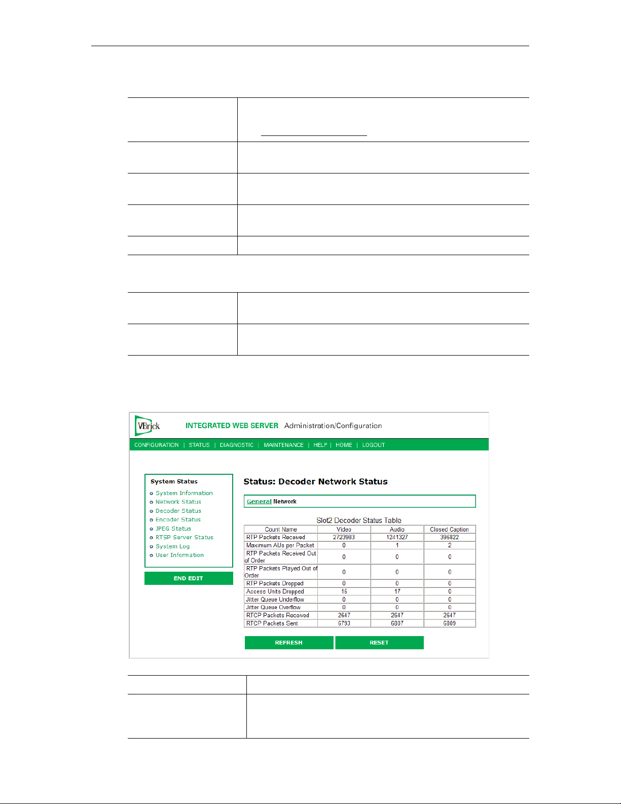
System Status
Audio
Audio Format The format for the audio stream this decoder is receiving in the
format:
(see Audio Template Settings
Target Audio Bit Rate The estimated audio bit rate from the encoder for the audio
stream this decoder is receiving.
xxx/<Stereo, Mono> where xxx is the Sample Frequency
). For example: 48000/Stereo
Measured Audio Bit
Rate
Audio Frames
Decoded
Bad Audio Frames The number of audio frames that could not be decoded.
The measured bit rate for the audio stream being played by this
decoder.
The number of frames decoded for the audio stream being played
by this decoder.
Closed Caption
Measured CC Bit Rate Reports the measured bit rate for the closed caption stream
displayed by the decoder.
CC Frame Rate Reports the frame rate for the closed caption stream displayed by
the decoder
Status: Decoder Status > Network
This status window provides packet statistics for the connection.
RTP Packets Received The number of RTP packets received.
Maximum AUs per
Packet
VBrick MPEG-4 Appliance Admin Guide 69
Maximum access units per RTP packet. The video maximum is
0 or 1; the audio maximum varies by source; the closed caption
maximum is set in the encoder.
Page 80

RTP Packets Received
Out of Order
The number of RTP packets received that were out of order.
RTP Packets Played Out
of Order
The VBrick decoder also uses the Jitter Queue to correct
packets that are received out of order. If the packet statistics
indicate a significant number of
Order
you may be able to improve video and audio quality by
RTP Packets Played Out of
increasing the setting in Configuration: Decoder > RTP > Time
in Jitter Queue. If you see
even with a large
Time in Jitter Queue setting, the network is
RTP Packets Played Out of Order,
losing packets.
RTP Packets Dropped The number of RTP packets dropped.
Access Units Dropped The number of access units dropped by the RTP receiver. AU
packets may be automatically adjusted to account for
differences in timing between the encoder and decoder.
Jitter Queue Underflow The VBrick decoder has an adjustable
Time in Jitter Queue to
protect against depletion by network jitter (see Configuration:
Decoder > RTP on page 22). If the packet statistics indicate a
significant number of
Jitter Queue Underflow counts you should
increase the setting in Configuration: Decoder > RTP > Time
in Jitter Queue to allow the decoder to handle more network
jitter.
Jitter Queue Overflow An overflow occurs when there is an overflow in the buffer
capacity of the VBrick.
RTCP Packets Received The number of RTCP packets received.
RTCP Packets Sent The number of RTCP packets sent.
Status: Encoder Status
This menu allows users to view vital Encoder statistics. As you Refresh you should see
Transmit State – Transmitting and the IP Bytes Transferred count should increment. If this
does not happen check your VBrick's encoder configuration or network.
70 © 2009 VBrick Systems, Inc.
Page 81
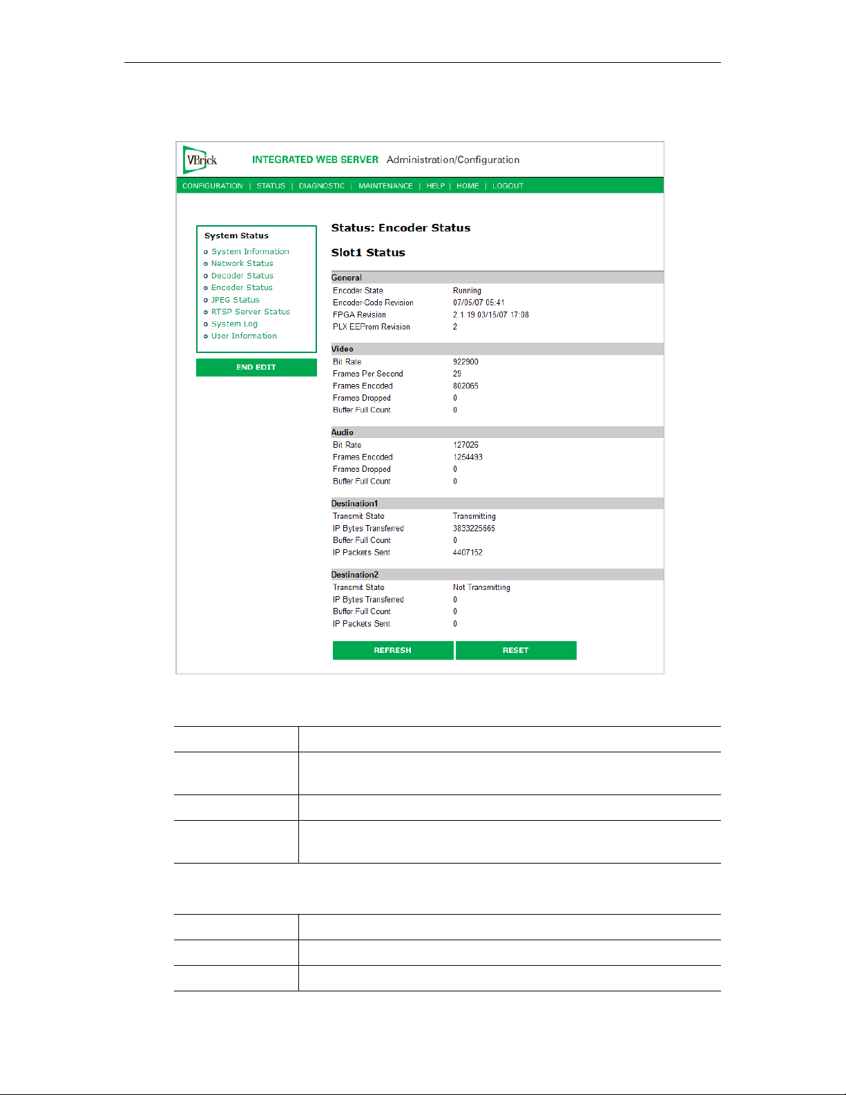
Slot1 Status
System Status
General
Encoder State Displays encoder state as running or not running.
Micro-Code
Revision
FPGA Revision Displays the FPGA revision number.
PLX EEProm
Revision
Displays the encoder micro-code revision.
Displays the EEProm revision number.
Video
Bit Rate Displays the video bit rate.
Frames per Second Displays the number of frames per second.
Frames Encoded Displays the number of frames encoded.
VBrick MPEG-4 Appliance Admin Guide 71
Page 82
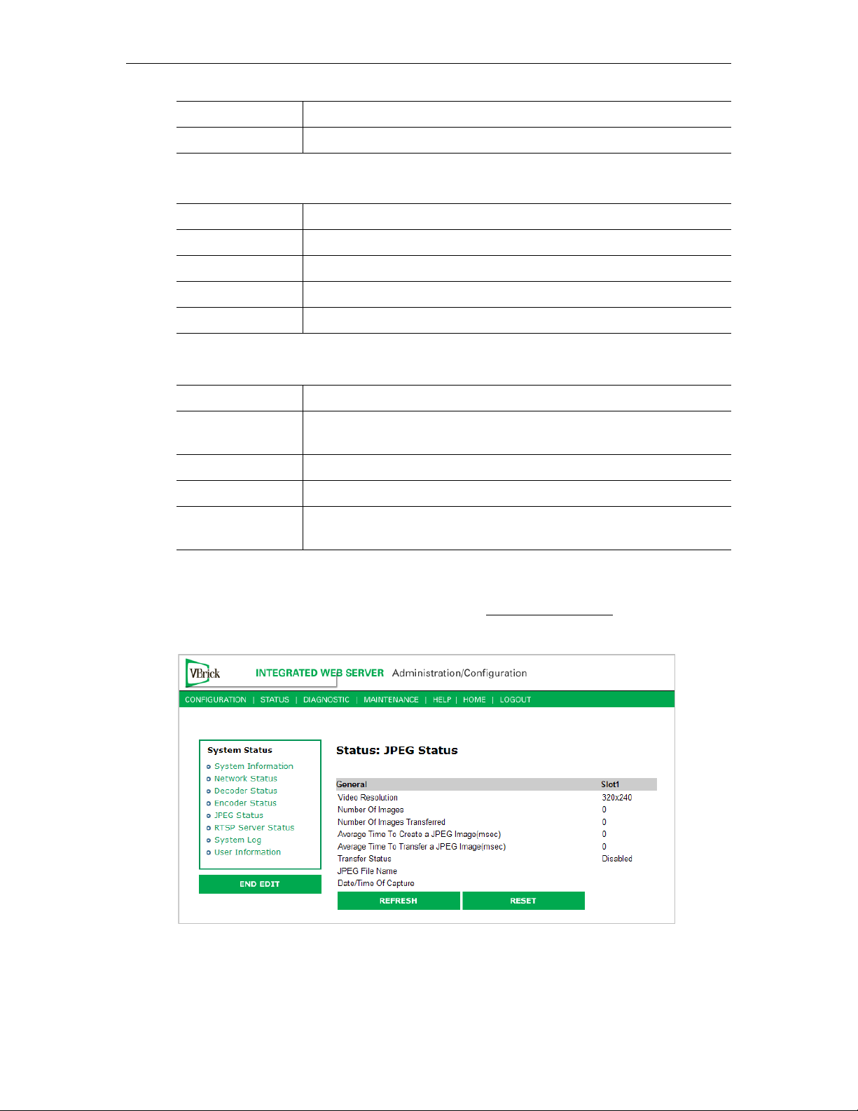
Frames Dropped Displays the number of frames dropped in the counted frames.
Buffer Full Count Displays how many times the buffer full count has been reached.
Audio
Bit Rate Displays the audio bit rate.
Frames per Second Displays the number of frames per second.
Frames Encoded Displays the number of frames encoded.
Frames Dropped Displays the number of frames dropped in the counted frames.
Buffer Full Count Displays how many times the buffer full count has been reached.
Destination and Slot
Transmit State Transmitting, not transmitting.
IP Bytes
Transferred
Buffer Full Count Displays any full buffer counts that occur.
IP Packets Sent Displays the number of packets sent.
Refresh The screen is static. Use the
Number of bytes transferred from the encoder daughter card to the
main board.
display current information.
Status: JPEG Status
Displays JPEG image capture status if enabled. See Configuration: JPEG on page 40 for
more about configuration.
Refresh button to updates the screen to
72 © 2009 VBrick Systems, Inc.
Page 83

System Status
Video Resolution Resolution of snapshots determined by the configuration of the
associated MPEG-4 encoder. One of the following:
SIF (352x240)
QSIF (160x120)
CIF (352x288)
QCIF (176x144)
384x288
320x240
256x192
192x144
128x96
64x48
Number of Images Number of images captured since capture was enabled.
Number of Images
Transferred
Average Time to
Create ...
Average Time to
Transfer ...
Transfer Status • Success – compressed snapshot successfully transferred to the
JPEG File Name Name of .jpg file being transferred to server.
Date/Time of
Capture
Number of images transferred since capture was enabled. If the
number of snapshot transfers is lower than the number of snapshots,
the create time plus the transfer time is likely greater than the
configured snapshot interval.
Milliseconds. Average time to create each snapshot over the last 10
snapshots.
Milliseconds. Average time to transfer the snapshots from the VBrick
to the server over the last 10 transfers.
server. Waiting to capture another image.
• Transfer in progress.
• Timeout – Transfer failure due to timeout. Indicates a network
error, server error, or error in configuring the snapshot FTP page.
• Rejected – Transfer failure due to invalid user name or password.
• Aborted – Not enough space on server.
• Disabled – Snapshot capture is disabled.
Date and time of last successful capture.
Status: RTSP Server Status
Status: RTSP Server Status > General
MPEG-4 only.
VBrick MPEG-4 Appliance Admin Guide 73
Page 84
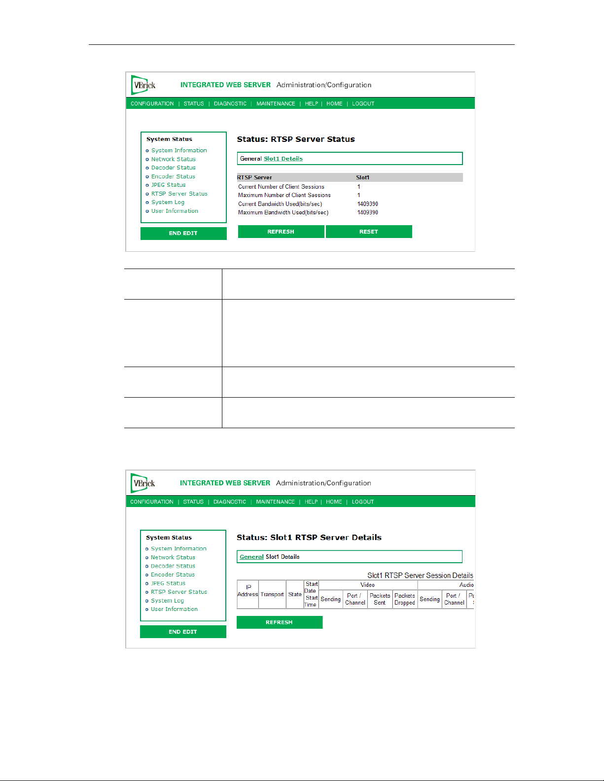
Current Number of
Client Sessions
Displays current number of sessions.
Maximum Number
of Client Sessions
Current Bandwidth
Used
Maximum Bandwidth
Used
Displays the maximum number of sessions that have been
simultaneously operating since the status was reset. This setting
enables control of the maximum number of RTSP clients allowed.
Currently a unit can support up to 120. A value of 0 disables the
RTSP server.
Displays the current bandwidth used in bits per second.
Displays the maximum bandwidth used at any point in time since
status was reset.
Status: RTSP Server Status > Slot1 Details
74 © 2009 VBrick Systems, Inc.
Page 85
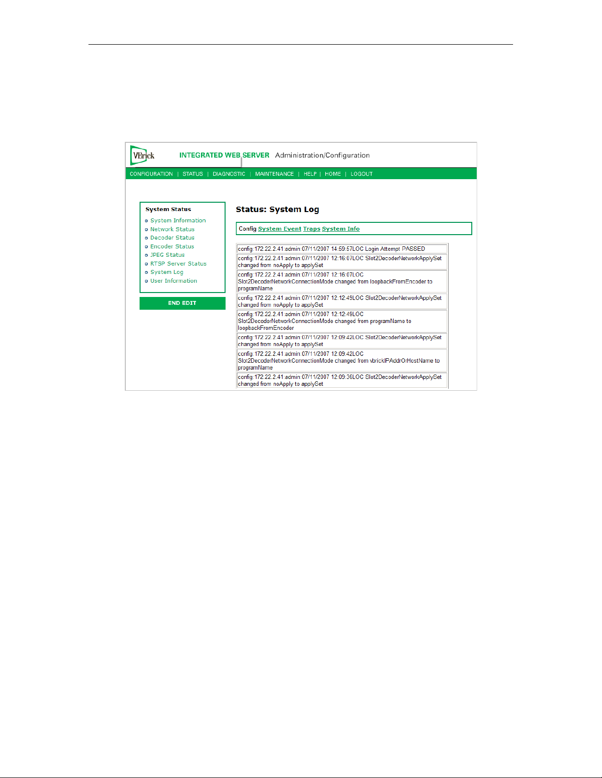
Status: System Log
Status: System Log > Config
This log contains a list of the latest VBrick configuration changes.
System Status
Status: System Log > System Event
The system event log contains reports of system events within the VBrick. These events may
occur during normal operation and include reports of successful and unsuccessful attempts
to access video sources by the local decoder and access to the local encoder using RTSP.
VBrick MPEG-4 Appliance Admin Guide 75
Page 86
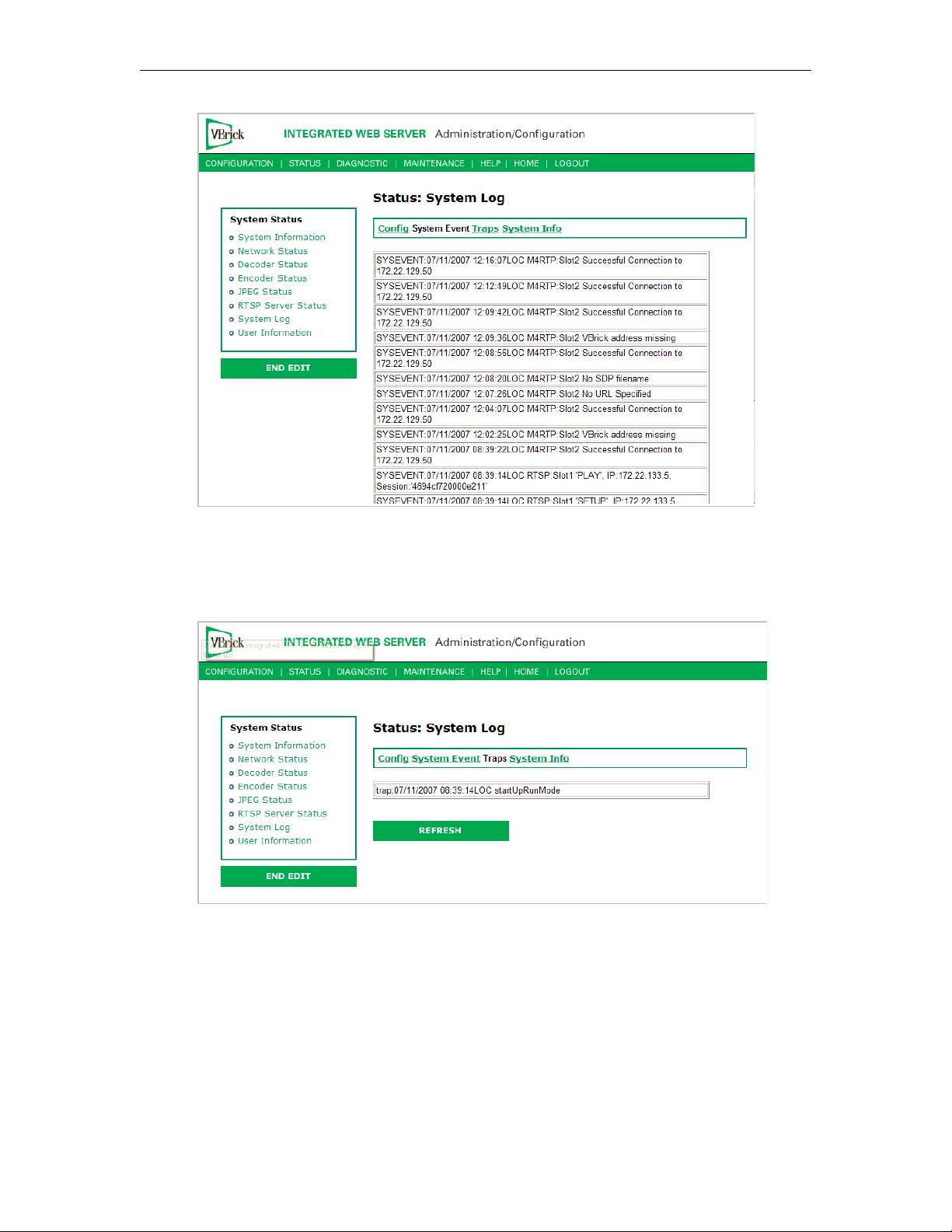
Status: System Log > Traps
This log contains all of the SNMP traps generated by the box whether or not the traps have
been emitted.
Status: System Log > System Info
This log contains unexpected behaviors detected by the VBrick software. Normally this log is
used by VBrick Customer Support to help debug possible system malfunctions.
76 © 2009 VBrick Systems, Inc.
Page 87
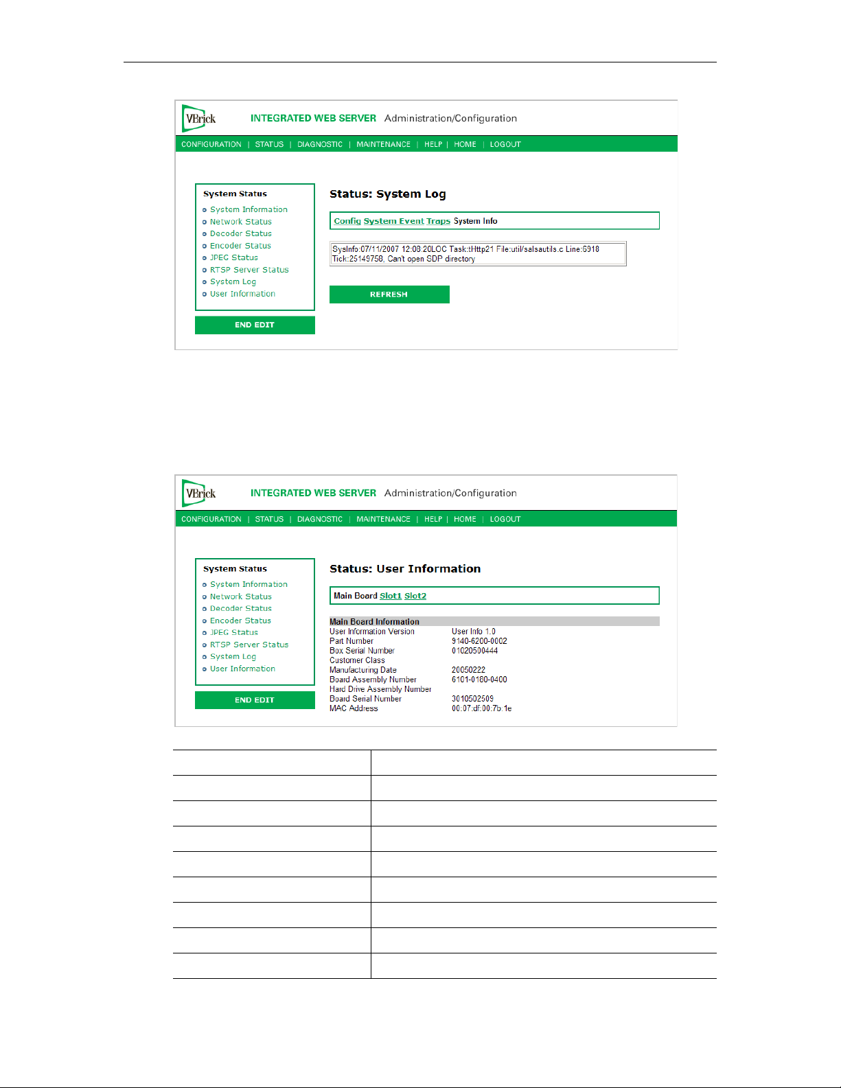
Status: User Information
Status: User Information > Main Board
System Status
This menu allows the user to view factory-set information regarding the main board.
User Information Version As displayed.
Part Number As displayed.
Box Serial Number As displayed.
Customer Class As displayed if any.
Manufacturing Date As displayed.
Board Assembly Number As displayed if any.
Hard Drive Assembly Number As displayed if any.
Board Serial Number As displayed.
MAC Address As displayed.
VBrick MPEG-4 Appliance Admin Guide 77
Page 88
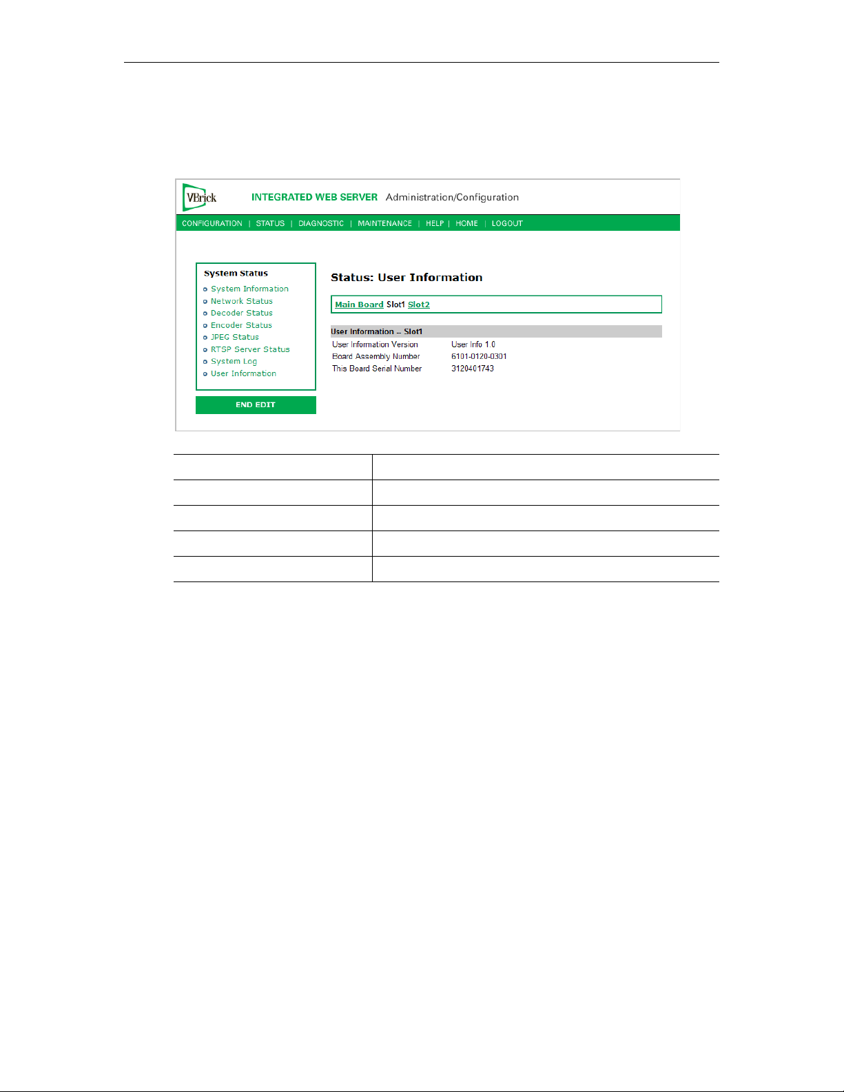
Status: User Information > Slot1/Slot2
This menu allows the user to view factory set information relative to the slots in the
appliance.
User Information Version As displayed.
Board Assembly Number As displayed.
Lot Number As displayed if any.
Main Board Serial Number As displayed.
This Board Serial Number As displayed.
78 © 2009 VBrick Systems, Inc.
Page 89

Diagnostics
Topics in this chapter
Overview . . . . . . . . . . . . . . . . . . . . . . . . . . . . . . . . . . . . . . . . . . . . . . . . . . . . . . . . . . . . . . . . 79
Diagnostics: Network Tests . . . . . . . . . . . . . . . . . . . . . . . . . . . . . . . . . . . . . . . . . . . . . . . . . . 80
Diagnostics: Device Test . . . . . . . . . . . . . . . . . . . . . . . . . . . . . . . . . . . . . . . . . . . . . . . . . . . . 82
Diagnostics: Decoder Color Bars . . . . . . . . . . . . . . . . . . . . . . . . . . . . . . . . . . . . . . . . . . . . . 83
Overview
There are two groups of diagnostics: Low Level Hardware Diagnostics and User Diagnostics.
Low Level diagnostics are run in Diagnostics mode. User diagnostics are run in normal Run
mode. (The Configured Operational Mode is set in Configuration: System as described below.)
You must be in
Tests. You can run all other tests from Run mode.
Diagnostics mode to run Hard Drive Check Disk and Device Test POST
Chapter 4
Note Since running in
the appliance to the
operational state.
T To change between normal Run mode and Diagnostics mode
1. Log in with Administrator or Operator Privilege. The default login Username and
Password is
2. Go to the
3. Click
4. Set
5. Click
6. The VBrick will then automatically save the changes and reset.
Configured Operational Mode as required.
admin/admin or operator/operator (case sensitive).
Configuration: System screen.
Begin Edit.
Apply Changes.
Diagnostics mode interrupts the passing of video, be sure to return
Run mode in order to return the appliance to its normal
Low-Level Hardware Diagnostics
These are tests that test the hardware integrity of the VBrick appliance board and are not
often used. If they are necessary, the tests can be set for continuous operation or for a certain
number of test loops, and run at low or high intensity. Note that depending on the model, a
low intensity test sequence may take 5-15 seconds per test sequence; a high intensity test
sequence can take 5-15 minutes or more.
User Diagnostics
There are three user diagnostics: Network Test, Device Test, and Decoder Color Bar.
VBrick MPEG-4 Appliance Admin Guide 79
Page 90
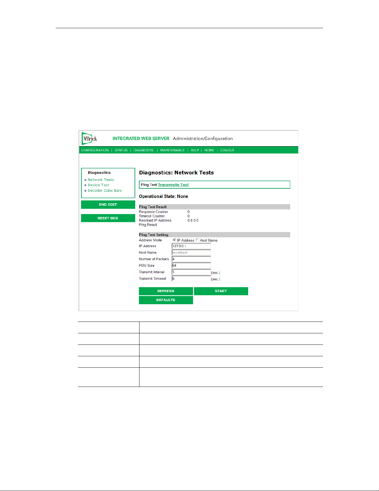
Diagnostics: Network Tests
Diagnostics: Network Tests > Ping Test
This menu allows the user to initiate a data test from one VBrick to another. To Ping another
VBrick, it's necessary to enter Edit mode. Enter the IP address and Test Settings and select
the
Start button. The Operational State will read Ping Test. After the test is completed, use
the Refresh button to display the results of the test. The results of the test will be displayed in
the top portion of the screen. If the test is interrupted by pressing the Stop button, the
results of the test prior to termination will be displayed.
Address Mode Select IP Address or Host Name and enter a corresponding value.
Number of Packets Number of packets to send for the test (default is 4).
PDU Protocol Description Unit size of packets, in bytes (default is 64).
Transmit Interval In seconds (default is sending the packets in 1 second intervals).
Transmit Timeout The length of time, in seconds, before the test times out, in the
event the target device fails to respond.
Diagnostics: Network Tests > Traceroute Test
The Internet is a large and complex aggregation of network hardware, connected together by
gateways. Tracking the route packets follow or finding a gateway where the packets are being
discarded is difficult. The Trace Route test attempts to trace the route an IP packet follows to
a specified Internet host. This test utilizes the Time To Live (TTL) field in the IP header to
allow intermediate nodes to be "discovered" via Internet Control Message Protocol (ICMP).
80 © 2009 VBrick Systems, Inc.
Page 91
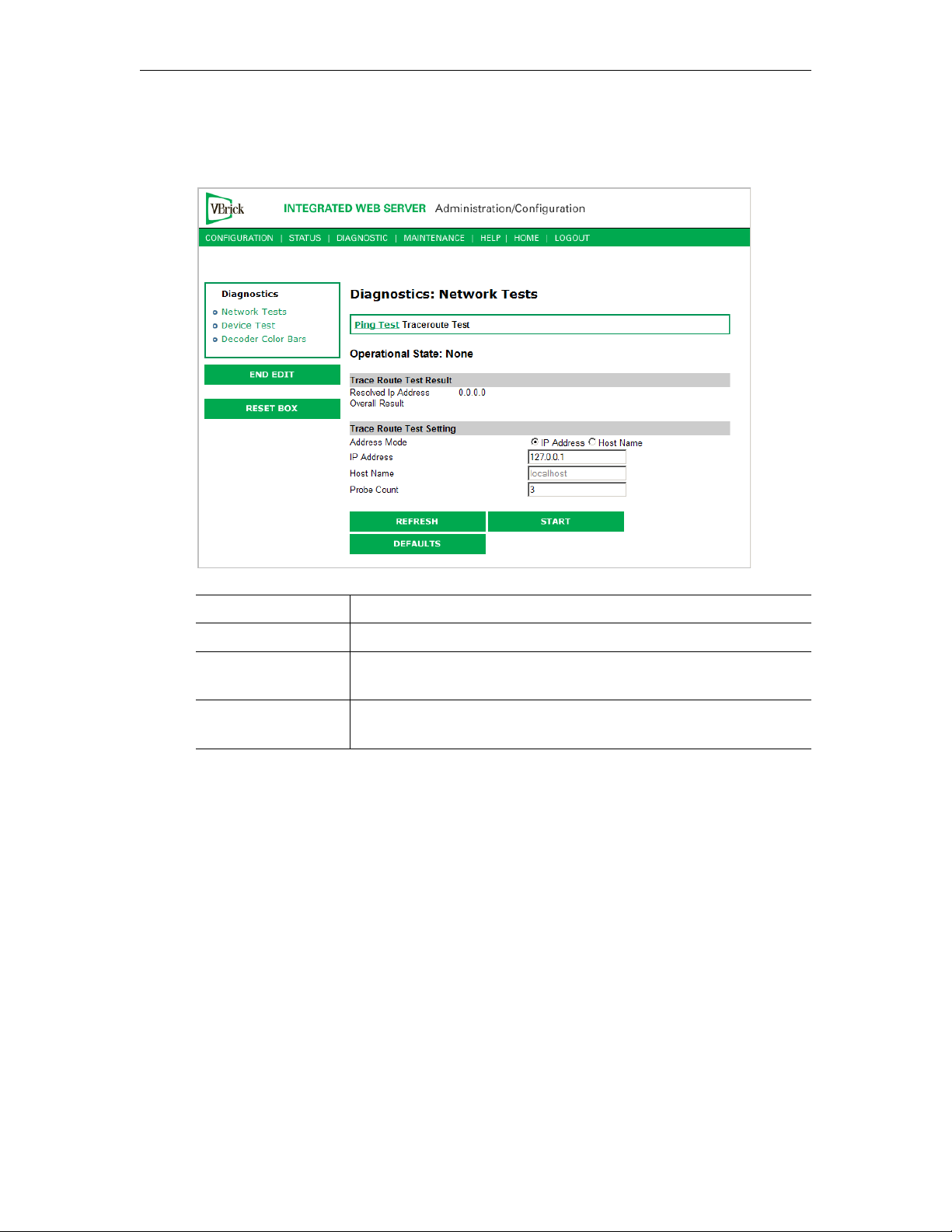
Diagnostics
Intermediate hops are discovered by launching probe packets with a small TTL and then
listening for an ICMP Time Exceeded reply from a gateway. Use Refresh, Start/Stop, and
Default to run the test.
Operational State The currently selected test.
Address Mode Select IP Address or Host Name and enter a corresponding value.
IP Address or Host
Enter the information in the corresponding box.
Name
Probe Count Can be set from 3 to 20. The default setting is 3. This setting is the
number of probe packets sent to a host at each hop.
Tracer oute Test Results
The results of the test appear at the top of the screen. The results include the Resolved IP
Address of the Destination Host Name. When the test is finished or stopped, the Overall
Result will display the result of the test, such as "Test Done," or "Max hops (=30) Finished,"
or "Test Stopped," etc. An entry shows the hop number, which is equal to the TTL, IP
address (and Host Name if available) of the gateway, and round trip time of each probe. If the
probe answers are received from different gateways, the address of each responding system
will be shown. If there is no response within a 5 second timeout interval, a "*" is printed for
that probe. If the result string exceeds 255 characters, the string will be terminated by ending
it with "Too Long."
VBrick MPEG-4 Appliance Admin Guide 81
Page 92
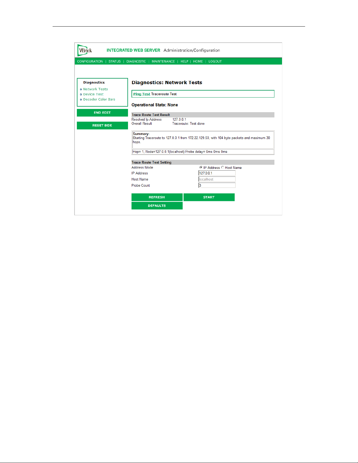
Diagnostics: Device Test
This screen shows the results of the Power-On Self Test, which is automatically run when the
VBrick is reset or powered on. Other than that, running this test allows the operator to test
the hardware integrity of the VBrick appliance board by running the test one or more times
or by setting the test for continuous operation or for a certain number of test loops. This test
is not often used. It is necessary to be in Diagnostic mode before running these tests. Enter
Diagnostic mode from the
mode after the tests are run. You must be in Edit mode before you can run this test. Test
Results include
Pass, Fail, Not Present.
Configuration > System screen. Don't forget to return to Run
82 © 2009 VBrick Systems, Inc.
Page 93
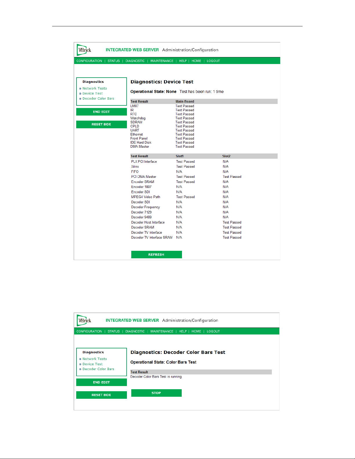
Diagnostics
Diagnostics: Decoder Color Bars
The Decoder Color Bar test is a simple test that generates color bars at the video decoder and
outputs them in the place of video. It can be used to test basic decoder operation and the
monitor.
VBrick MPEG-4 Appliance Admin Guide 83
Page 94

84 © 2009 VBrick Systems, Inc.
Page 95
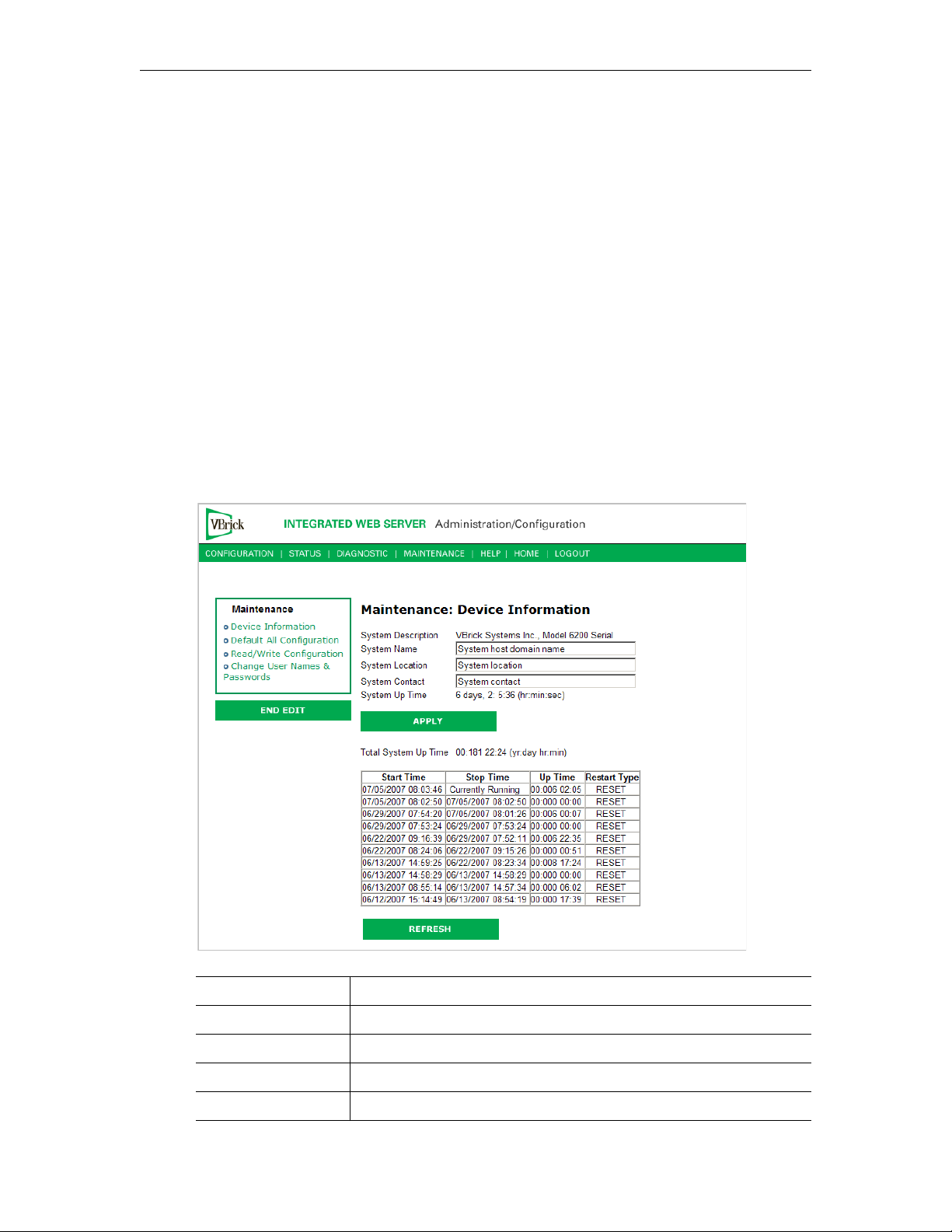
Maintenance
Topics in this chapter
Maintenance: Device Information . . . . . . . . . . . . . . . . . . . . . . . . . . . . . . . . . . . . . . . . . . . . . 85
Maintenance: Default All Configuration . . . . . . . . . . . . . . . . . . . . . . . . . . . . . . . . . . . . . . . . 86
Maintenance: Read/Write Configuration. . . . . . . . . . . . . . . . . . . . . . . . . . . . . . . . . . . . . . . . 86
Maintenance: Change Usernames & Passwords . . . . . . . . . . . . . . . . . . . . . . . . . . . . . . . . . . 89
Maintenance: Device Information
The device information menu allows the user to set various system information. These
parameters are often used in SNMP managed networks.
Chapter 5
System Description Company name, model and serial number of appliance.
System Name Name of the system (for example Hall 23-B).
System Location Location of system (for example Washington Building).
System Contact Contact name.
System Up Time Displays the time elapsed since the last system reset or power cycle.
VBrick MPEG-4 Appliance Admin Guide 85
Page 96
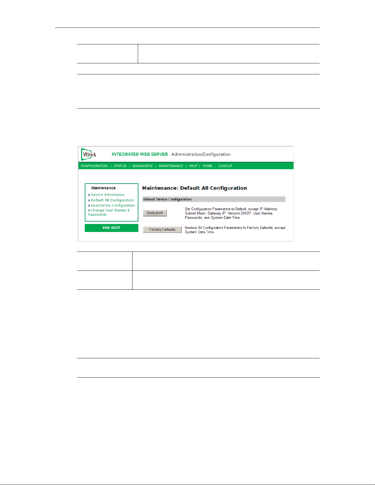
Total System Up
Time
Note The Device Information table creates a date and time stamp for every power or reset
event. When SNTP is enabled, the unit must reboot to synchronize time with the
SNTP server time. If the time moves dramatically forward (or backward), a
discontinuity may appear in the device table because of the SNTP time correction.
Displays the total time that the unit has been powered up.
Maintenance: Default All Configuration
This menu allows the user to default all the configuration parameters of the VBrick.
Default All Sets all parameters except IP address, Subnet Mask, Gateway IP, User
Names, Passwords and System Date Time.
Factory Defaults Sets all parameters to factory defaults with the exception of System
Date and Time.
Maintenance: Read/Write Configuration
Maintenance: Read/Write > Read From Device
The Read/Write Configuration page allows you to read configuration parameters from the
VBrick to a file, as well as write configuration parameters from a file to the VBrick. The file is
an .xml file and Internet Explorer is the assumed browser.
Note The VBrick appliance the .xml file is read from, and VBrick appliance the .xml file is
written to, must be running the same version of code.
86 © 2009 VBrick Systems, Inc.
Page 97
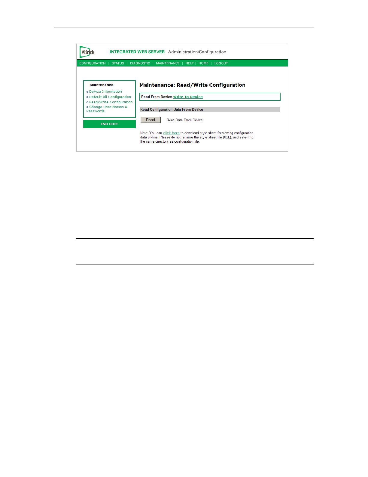
Maintenance
Read Configuration Data from Device
You can read the configuration parameters from the VBrick by clicking the Read button on
the page. After clicking on the button, an xml document with all the configuration
parameters will pop up (see Figure 5). The .xml document can then be saved to your PC as an
.xml file using
click here on the screen) to the same directory as the saved file. Do not change the name of
the style sheet. It should always be saved as cfgdata.xsl and the first line at the top of the
configuration file must always be:
href="cfgdata.xsl"?>
File > Save As. To view this file offline, you must download the style sheet (see
<?xml-stylesheet type="text/xsl"
Note Firefox users: To view and/or save the configuration file, click Read and then Save to
Disk
. Then use click here and save the stylesheet to disk. This will copy both items to
your desktop so you can view the configuration file using the stylesheet.
VBrick MPEG-4 Appliance Admin Guide 87
Page 98
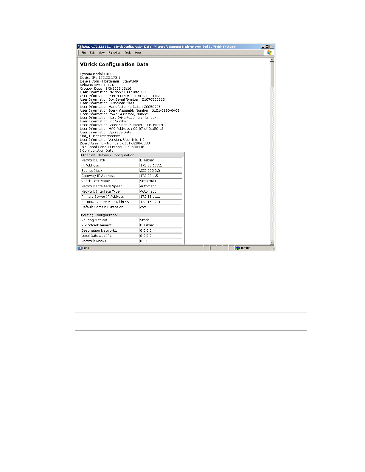
Figure 5. Sample VBrick Configuration File
Maintenance: Read/Write > Write To Device
This page lets you write configuration parameters from an .xml file to the VBrick. On a
successful write, all parameters will be saved to Flash and the appliance will reboot. Only
administrator level users and above have
Note The VBrick appliance that the configuration file is read from, and VBrick appliance
that the configuration file is written to must be running the same version of code.
Write privileges.
88 © 2009 VBrick Systems, Inc.
Page 99
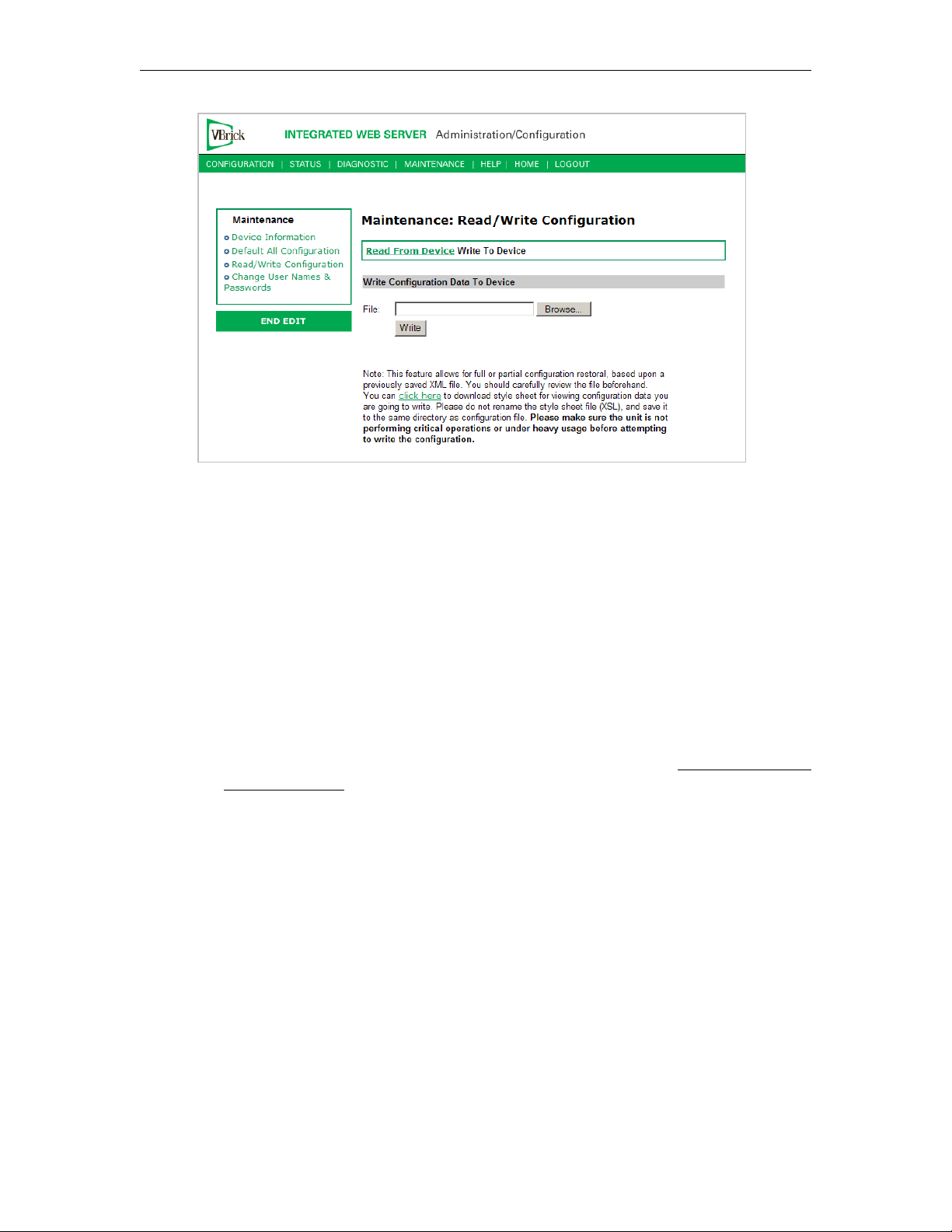
Write Configuration Data to Device
Maintenance
T To write configuration parameters to the VBrick from an .xml file
1. Click the
Browse button and navigate to the configuration file you want to write to the
appliance.
2. Click on the
Write button to write the selected file to the VBrick. The configuration
parameters will be saved to Flash memory and the appliance will reboot. In the event of
a validation error, a message will appear on the screen. Click on
Errors to view error
messages that might have caused the validation failure. The error list is not generated for
all types of write configuration failures so you may need to locate the error(s) manually
by clicking through the IWS pages in Edit mode and looking for error messages
highlighted in red.
T To create a configuration file
1. Read the configuration from the VBrick and save as an .xml file. See Read Configuration
Data from Device above.
2. Use any text editor, preferably an .xml editor to make changes to the file. You can change
the "values" field as well as delete objects as necessary. Make sure the right data types are
used. For example if a parameter takes integer values, do not enter a string. Also IP
Address parameters must have the right IP syntax. Enter "0.0.0.0" to enter a null IP
address. Blanks and null strings are not valid IP Addresses.
Maintenance: Change Usernames & Passwords
Maintenance: Usernames & Passwords > Change
Usernames and Passwords
This page lets an Administrator change usernames and passwords for security purposes.
VBrick MPEG-4 Appliance Admin Guide 89
Page 100
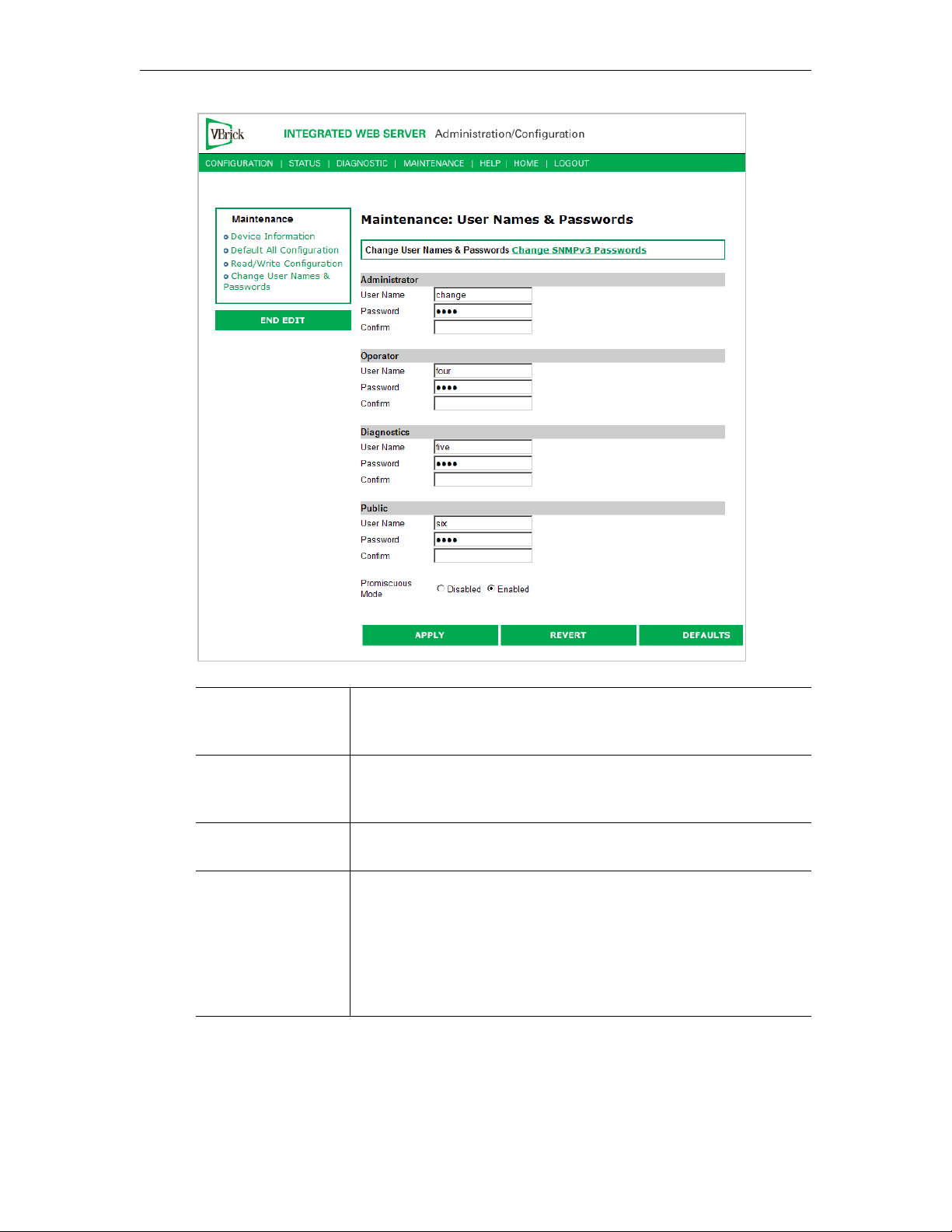
User Name Enter desired user name. Cannot exceed 20 characters. It may
include any combination of alphanumeric characters and only the
following special characters:
~ ! # $ ^ * + & [ ] { } | < >
Password Enter desired password. Cannot exceed 20 characters. It may
include any combination of alphanumeric characters and only the
following special characters:
~ ! # $ ^ * + & [ ] { } | < >
Confirm Confirm new password entry. Note: Appliance will then inform the
user and perform a reboot.
Promiscuous Mode This mode is used in conjunction with VBrick supplied ActiveX
controls. In promiscuous mode, no login or password is required.
When using the associated ActiveX components in this mode, either
the login password should be set to blank, (" ") or to the legal
administrated login/password. If promiscuous mode is disabled, the
legal administrator login/password must be entered when
configuring or using these controls.
90 © 2009 VBrick Systems, Inc.
 Loading...