

VBox Home TV Gateway
XTi Product Family:
User Manual
Product Version: 2.57
Release Date: April 2017
Document Revision: 2.02

Dear VBox Home TV Gateway Owner,
Thank you for purchasing a VBox Home TV Gateway, personal
home TV router and PVR.
You’ve joined the many people who watch and record live TV
over IP — and the VBox TV revolution.
To get the best performance from your VBox TV Gateway, please
take a few moments to read this manual and get acquainted
with it. If you have any questions, please visit
www.vboxcomm.com for more information.
To learn how to connect your devices to the VBox TV Gateway
check our Player and Apps page -
http://www.vboxcomm.com/players
I also encourage you to register your VBox TV Gateway now at
http://www.vboxcomm.com/shop-support/productregistration.html, to like us on Facebook, to follow us on twitter
and YouTube.
By following VBox, you’ll instantly start enjoying these exclusive
benefits:
Get product updates and other valuable information: Be among
the first to find out about new features and updates.
When you register, you can also tell us about your experience
with your TV Gateway; VBox listens to our customers and makes
enhancements to the TV Gateway based on your valued
feedback. We’d love to hear from you!
On behalf of the entire team, thank you for choosing
VBox. We appreciate your business, feedback and loyalty.
P.S don’t forget to follow us on Facebook, Twitter and YouTube
to learn about new features and product updates
facebook.com/VBoxComm | twitter.com/VboxComm
http://www.youtube.com/channel/UCffljNeXAB5R7ee9SyOCjWQ
Welcome!

Figures
Contents
1 Introduction to XTi–VBox TV Gateway ........................................................................................................... 1
1.1 XTi-VBox TV Gateway family Product Line ............................................................................................. 1
1.2 About this Guide ..................................................................................................................................... 2
1.2.1 Document Conventions .................................................................................................................. 3
2 Front and Rear Panels ..................................................................................................................................... 4
2.1 Front Panel XTi-33XX models .................................................................................................................. 4
2.2 Front Panel XTi-34XX models .................................................................................................................. 5
2.3 Rear Panels ............................................................................................................................................. 5
2.3.1 XTi-3332 Dual Tuner Satellite Rear Panel ....................................................................................... 5
2.3.2 XTi-3340-50 CI Rear Panel ............................................................................................................... 7
(See How to switch between DVB-T and DVB-C Configuration in Paragraph 14.1) ........................................... 7
2.3.3 XTi-3342-52 CI Rear Panel ............................................................................................................... 8
2.3.4 XTi-3442-52 Rear Panel ................................................................................................................... 9
3 Connecting XTi-VBox TV Gateway to your Home Network .......................................................................... 10
3.1 Package Contents .................................................................................................................................. 10
3.2 Additional Required Equipment ........................................................................................................... 10
3.3 Installing the XTi-VBox TV Gateway Device .......................................................................................... 10
3.4 Configure the XTi-VBox TV Gateway using Tablet / iPad ...................................................................... 10
4 Configuring your Router and PC to Use the UPnP Protocol ......................................................................... 11
4.1 Accessing XTi-VBox TV Gateway on PC using “My Network Places” .................................................... 11
4.2 Accessing XTi-VBox TV Gateway from Mac OS X .................................................................................. 13
5 Setting up XTi-VBox TV Gateway using the Web Interface........................................................................... 14
5.1 Step 1 – System Setup .......................................................................................................................... 14
5.2 Step 2 – Tuners Setup ........................................................................................................................... 17
5.2.1 Step 2 – Tuners Setup for XTi 3332 Dual Tuner ............................................................................ 18
5.2.2 Step 2 – Tuners Setup for XTi 3340/3442/3350/3452 Models ..................................................... 21
5.3 Step 3 – Scan ......................................................................................................................................... 23
5.3.1 Step 3 – Scan for XTi 3332 Dual Tuner Models ............................................................................. 23
5.3.2 Step 3 – Scan for XTi 3340/3442/3350/3452 ................................................................................ 25
5.4 Step 4 – Channels Setup ....................................................................................................................... 28
6 System Manage ............................................................................................................................................. 31
6.1 Verifying Current System, Device and Software Status ........................................................................ 31
6.2 Manage System ..................................................................................................................................... 32
Figure 24 Manage ............................................................................................................................................. 32
iii

6.3 System Services ..................................................................................................................................... 33
6.4 WEB Manage Protection ....................................................................................................................... 34
6.5 Backup and Restore (beta).................................................................................................................... 37
6.5.1 Backup ........................................................................................................................................... 37
6.5.2 Restore .......................................................................................................................................... 37
6.5.3 Reset to Factory Default ............................................................................................................... 38
6.6 Remote Access (beta) ........................................................................................................................... 39
6.6.1 Internet Bandwidth ....................................................................................................................... 39
6.6.2 How to Configure Remote Access ................................................................................................. 39
6.7 Update Software ................................................................................................................................... 41
6.7.1 Update over the Internet .............................................................................................................. 41
6.7.2 Update from a file ......................................................................................................................... 41
6.8 Manage Files ......................................................................................................................................... 44
Figure 26 Manage files ...................................................................................................................................... 44
6.9 System Logger ....................................................................................................................................... 45
7 Streaming option .......................................................................................................................................... 46
7.1 Streaming Status ................................................................................................................................... 46
7.2 Manage Channels ................................................................................................................................. 47
7.2.1 Sorting Channels ........................................................................................................................... 48
7.2.2 Changing Channel Logo ................................................................................................................. 48
7.3 Program Guide ...................................................................................................................................... 51
7.3.1 Live Signal ...................................................................................................................................... 51
7.3.2 Live Signal with Channel Pairing ................................................................................................... 52
7.3.3 External XMLTV (beta) .................................................................................................................. 53
7.4 Add Channels ........................................................................................................................................ 54
7.5 Language Settings. ................................................................................................................................ 54
7.6 UPnP Support ........................................................................................................................................ 55
7.7 IPTV Support ......................................................................................................................................... 55
8 Tuners ........................................................................................................................................................... 57
9 Quick Setup ................................................................................................................................................... 58
10 Network Status ......................................................................................................................................... 59
11 Shutting Down and Restarting the System ............................................................................................... 60
12 Players ....................................................................................................................................................... 61
12.1 Mobile Devices ...................................................................................................................................... 61
12.2 3rd Party Applications – UPnP ............................................................................................................. 61
12.2.1 PC and Mac ................................................................................................................................... 61
12.2.2 Tablet and Smartphone ................................................................................................................ 62

13 Recording .................................................................................................................................................. 63
13.1 Hardware installation ........................................................................................................................... 63
13.1.1 Attached Storage (default) ........................................................................................................... 63
13.1.2 Network Storage ........................................................................................................................... 64
13.1.3 Network Storage (NAS) Shared folder .......................................................................................... 66
13.2 Setting-up V@Home TV Gateway Storage Preferences ....................................................................... 67
13.2.1 Manage recording page ................................................................................................................ 67
13.2.2 Setting up network storage .......................................................................................................... 68
13.3 Using the VBox@TV applications .......................................................................................................... 73
13.3.1 Recording a live TV show .............................................................................................................. 73
13.3.2 Recording a future TV show .......................................................................................................... 74
13.4 Recording a series TV show (beta) ........................................................................................................ 74
13.4.1 Automatic Series Recording .......................................................................................................... 74
13.4.2 EPG Series Recording .................................................................................................................... 75
13.4.3 Manual Series Recording .............................................................................................................. 75
13.5 Watch a recorded program .................................................................................................................. 76
14 Frequently Asked Questions/Troubleshooting ......................................................................................... 77
14.1 How to switch between DVB-T and DVB-C Configuration. ................................................................... 77
14.2 Enabling UPnP (Universal Plug and Play) in a Windows-based computer ............................................ 82
Figures
Figure 1: XTi 33XX Front Panel ................................................................................................................................ 4
Figure 1: XTi 34XX Front Panel ................................................................................................................................ 5
Figure 2: XTi 3332 Dual Tuner (Model Dual Tuner Satellite) – Rear Panel ............................................................. 5
Figure 3: XTi 3342-52 / 3340-50 /CI – Rear Panel ................................................................................................... 7
Figure 4: XTi 3342CI Dual Tuner (Terrestrial or Cable) – Rear Panel ...................................................................... 8
Figure 4: XTi 3442 Dual Tuner (Terrestrial or Cable) – Rear Panel ......................................................................... 9
Figure 5: Windows XP – My Network Places showing VBox TV Gateway ............................................................ 11
Figure 6: Windows 7 – Network Media Devices showing VBox TV Gateway ....................................................... 12
Figure 7: VBox TV Gateway interface – Welcome page ....................................................................................... 13
Figure 8: Quick Setup Wizard – Step 1 – System Setup: Device Configuration page ........................................... 14
Figure 9: Quick Setup Wizard – Step 1 – System Setup: System Settings page .................................................... 15
Figure 10: Quick Setup Wizard – Step 1 – System Setup: Streaming Settings page ............................................. 16
Figure 11: Quick Setup Wizard– Step 2 – Tuners Setup: Tuner 1 page (XTi-3332 Dual Tuner) ............................ 18
Figure 12: Quick Setup Wizard– Step 2 – Tuners Setup: Tuner 2 page (XTi-3332 Dual Tuner) ............................ 20

Figure 13: Quick Setup Wizard – Step 2 – Tuners Setup: Tuners 3 + 4 page (XTi-334X/5X) ................................. 21
Figure 14: Quick Setup Wizard – Step 3 –Scan: Scan Settings Review page (XTi-3332 model) .................................. 23
Figure 15: Quick Setup Wizard – Step 3 –Scan: Scan Status and Results page (XTi-3332 models) ...................... 24
Figure 16: Quick Setup Wizard – Step 3 –Scan: Scan Settings Review page (XTi-3340) ............................................. 25
Figure 17: Quick Setup Wizard – Step 3 –Scan: Scan Status and Results page (XTi-3332 models) ...................... 26
Figure 18: Quick Setup Wizard – Step 4: Channels Setup page ............................................................................ 28
Figure 19: XTi-VBox TV Gateway Interface – Example System Status page ......................................................... 30

VBox V@Home TV Gateway User Manual 1. Introduction to XTi–VBox TV Gateway
Product Name
33XX family
Model Name
Supported
Broadcasts
Simultaneous
Users Served
RF
Connectors
CI
XTi-3332
Dual Tuner Satellite – FTA
Satellite – DVB-S/S2
2
2 - XTi-3442
Dual Tuner Terrestrial – FTA
Terrestrial – DVB-T/T2
2 1 -
XTi-3342 CI
Dual Tuner Terrestrial – Pay TV
Terrestrial – DVB-T/T2
2 1 +
XTi-3340
Combi Satellite & Terrestrial
– FTA
Terrestrial DVB-T2 &
Satellite DVB-S/S2
4
2x DVB-S/S2
1x DVB-T
-
XTi-3340 CI
Combi Satellite FTA &
Terrestrial CI & FTA – Pay TV
Terrestrial DVB-T
Satellite DVB-S/S2
4
2x DVB-S/S2
1x DVB-T
+
XTi-3452
Dual Tuner Cable – FTA
Cable – DVB-C
2 1 -
XTi-3352 CI
Dual Tuner Cable – Pay TV
Cable – DVB-C
2 1 +
XTi-3350
Combi Satellite & Cable
– FTA
Cable DVB-C &
Satellite DVB-S/S2
4
2x DVB-S/S2
1x DVB-C
-
XTi-3350 CI
Combi Satellite FTA &
Cable CI & FTA – Pay TV
Terrestrial DVB-C
Satellite DVB-S/S2
4
2x DVB-S/S2
1x DVB-C
+
1.1. XTi-VBox TV Gateway family Product Line
1 Introduction to XTi–VBox TV Gateway
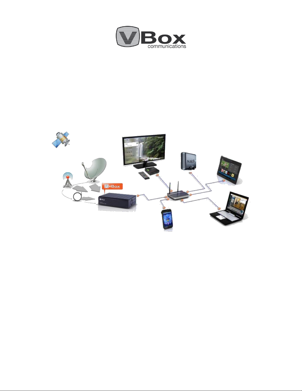
XTi-VBox TV Gateway is a TV router that gives you the freedom to consume all types of television broadcasts satellite (DVB-S/S2), cables (DVB-C) and terrestrial (DVB-T/T2) - through a single media gateway.
XTi-VBox TV Gateway eliminates the constraints to physical cables, by using an IP infrastructure.
You can receive different types of media from various sources, and share them with any computer, laptop,
tablet, Smartphone, Android Box or IP-STB device connected to your Local Area Network (LAN).
1.1 XTi-VBox TV Gateway family Product Line
XTi-VBox TV Gateway includes several products: Satellite XTi-333X, Terrestrial XTi-3X4X and Cable XTi-3X5X. Each
product is available in one or more models. Table 1 lists the products and their models and summarizes their
specifications.
Table 1: XTi-VBox TV Gateway Product List and Specifications
Model Name–indicates the model’s specifications:
Dual Tuner – receives either satellite, terrestrial or cable, live TV broadcasting from single or two coaxial cables, and
distributes this content through two tuners.
Combi – receives two different TV sources in a single VBox device
FTA - support Free-To-Air television broadcasting
Pay TV – includes a Common Interface (CI) that supports Conditional Access Modules (CAM), used for Pay TV content.
Supported Broadcasts– the number and types of different broadcasts that this device can receive simultaneously
2 Satellite–can receive two simultaneous broadcasts from a satellite (DVB-S/S2)
2 DVB-T– can receive two simultaneous broadcasts that are terrestrial (DVB-T/T2)
2 DVB-C– can receive two simultaneous broadcasts that are cables (DVB-C)
Tuners–the number of available tuners: two for Dual Tuner models or four for Combi models
RF Connectors–the number of available RF connectors:
One connector for models that receive Cable or Terrestrial broadcasts
Two connectors for models that receive Dual Tuner satellite broadcasts
Three connectors for Combi models that support both satellite broadcasts and terrestrial or cable broadcasts
CI–Pay TV - whether or not CI is supported.
1

VBox V@Home TV Gateway User Manual 1. Introduction to XTi–VBox TV Gateway
Item
Description
1
RF3– Connector for 2* Tuner (DVB-T//C)
(See diagram 3 below)
2
12V– power adapter connector
3
ON/OFF – Power button
4
LAN – RJ45 100 Mb (Ethernet cable) connector
5
USB – USB Connector
1.2. About this Guide
1.2 About this Guide
This guide includes the basic information you need to quickly setup your XTi device:
1. Front and Rear Panels (page 4) – describes the device’s front and rear panels.
2. XTi-3442-52 Rear Panel
3. XTi-3442-52 Dual Tuner 2T/2C has a rear panel with a single connector (RF3) for either two DVB-T/T2
tuners or
two DVB-C tuners (Figure 5). (See How to switch between DVB-T/T2 and DVB-C Configuration
Paragraph 14.1)
Figure 6: XTi 3442 Dual Tuner (Terrestrial or Cable) – Rear Panel
Diagram 4: XT1 3442 - Dual Tuner 2T/2C: Single Connector for Two DVB-T/T2 or DVB-C Tuners
4. Connecting XTi-VBox TV Gateway to your Home Network (page 9 ) – describes your package
contents, lists the system requirements and explains how to physically connect the device to your
network.
5. Configuring your Router and PC to Use the UPnP Protocol (page11) – explains how to enable UPnP,
in order to access your connected device through Windows Network Places.
6. Setting up XTi-VBox TV Gateway using the Web Interface (page 14) – explains how to use the VBox TV
Gateway Web interface to tune your device to a DVB-S transponder and/or a DVB-T or DVB-C channel.
For detailed information on advanced setup options, see the XTi –VBox TV Gateway User Guide.
2

VBox V@Home TV Gateway User Manual 1. Introduction to XTi–VBox TV Gateway
NOTE: Make sure you follow the instructions pertaining to your product and model.
1.2. About this Guide
1.2.1 Document Conventions
The guide covers the different XTi-VBox TV Gateway products using the following naming conventions:
Most of the information applies to all products in the XTi-VBox TV Gateway line.
In this case, the guide refers to the product line in general, using the abbreviation “XTi”.
Some information is exclusive to a particular product or model. In this case, the guide explicitly
specifies the product name or model name (as listed in Table 1: XTi-VBox TV Gateway Product List
and Specifications on page 1).
3

VBox V@Home TV Gateway User Manual 2. Front and Rear Panels
Item
Description
1
PowerLED– indicates whether the system is ready:
Orange–indicates the system is connected to electricity
but is still in the process of being started.
Green– indicates the XTi device is ready for use.
2-5
TunerLEDs – indicate the traffic status in tuners 1-4:
Steadygreenlight– indicates a locked frequency.
Blinkinggreenlight– indicates this tuner is transmitting data.
1
2 3 4
5
2.1. Front Panel XTi-33XX models
2 Front and Rear Panels
This section describes the front and rear panels of the XTi-VBox TV Gateway set-top box.
2.1 Front Panel XTi-33XX models
All XTi-VBox TV Gateway XTi-33XX share the same front panel, illustrated in Figure 1.
Figure 1: XTi 33XX Front Panel
Table 2: XTi Front Panel
4

VBox V@Home TV Gateway User Manual 2. Front and Rear Panels
Item
Description
1
ShutdownButton – Shutting down the VBox software by pressing
the shutdown button for 5 seconds. The XTi will continue to receive
power,
To launch the XTi software again please turn the XTi power off and
then turn the power on – using the Power Switch found at the back
of the XTi
2
PowerLED– indicates whether the system is ready:
Orange–indicates the system is connected to electricity
but is still in the process of being started.
Green– indicates the XTi device is ready for use.
3
TunerLEDs – indicate the traffic status in tuners 1-4:
Steadygreenlight– indicates a locked frequency.
Blinkinggreenlight– indicates this tuner is transmitting data.
1 2 3
2.2. Front Panel XTi-34XX models
2.2 Front Panel XTi-34XX models
All XTi-VBox TV Gateway XTi-34XX share the same front panel, illustrated in Figure 1.
Figure 2: XTi 34XX Front Panel
Table 3: XTi Front Panel
2.3 Rear Panels
This section describes the rear panel of each XTi-VBox TV Gateway product:
XTi-3332 Dual Tuner Satellite Rear Panel
XTi-3340-50 CI Rear Panel
XTi-3340-50 CI Rear Panel
XTi-3442-52 Rear Panel
2.3.1 XTi-3332 Dual Tuner Satellite Rear Panel
TheXTi-3332 Dual Tuner model includes two active RF connectors: one for each satellite tuners (Figure 3).
Figure 3: XTi 3332 Dual Tuner (Model Dual Tuner Satellite) – Rear Panel
5

VBox V@Home TV Gateway User Manual 2. Front and Rear Panels
Item
Description
1
RF1– Connector for Tuner-1 DVB-S/S2
2
RF2–Connector for Tuner-2 DVB-S/S2
3
5V–power adapter connector
4
ON/OFF– Power button
5
LAN– RJ45 100 Mb (Ethernet cable) connector
6
USB – USB Connector
See diagram2 bellow
RF2 Connector
Tuner 2
DVB-S2
RF1 Connector
Tuner 1
DVB-S2
3
4 5 6
1
2
2.3. Rear Panels
Diagram 1: XT1 3332 Dual Tuner – Two Connectors: One for Each Satellite Tuner
6
VBox V@Home TV Gateway User Manual 2. Front and Rear Panels
Item
Description
1
CAM/CI– Optional CI slot for DVB-T/C RF-3 only
2
RF1– Connector for Tuner-1 DVB-S2
3
RF2–Connector for Tuner-2 DVB-S
4
RF3– Connector for Tuner-3 DVB-T/C and tuner 4 DVB-T/C
5
5V– DC power adapter connector
6
ON/OFF– Power button
7
LAN– RJ45 100 Mb (Ethernet cable) connector
8
USB – USB Connector
Tuner 4
DVB-T/C
Tuner 3
DVB-T/C
Tuner 2
RF2 Connector
RF1 Connector
RF3 Connector
Tuner 1
DVB-S2
8 4 7 2 3 1 5
6
See diagram3 bellow
0. (See How to switch between DVB-T and DVB-C Configuration in Paragraph 14.1)
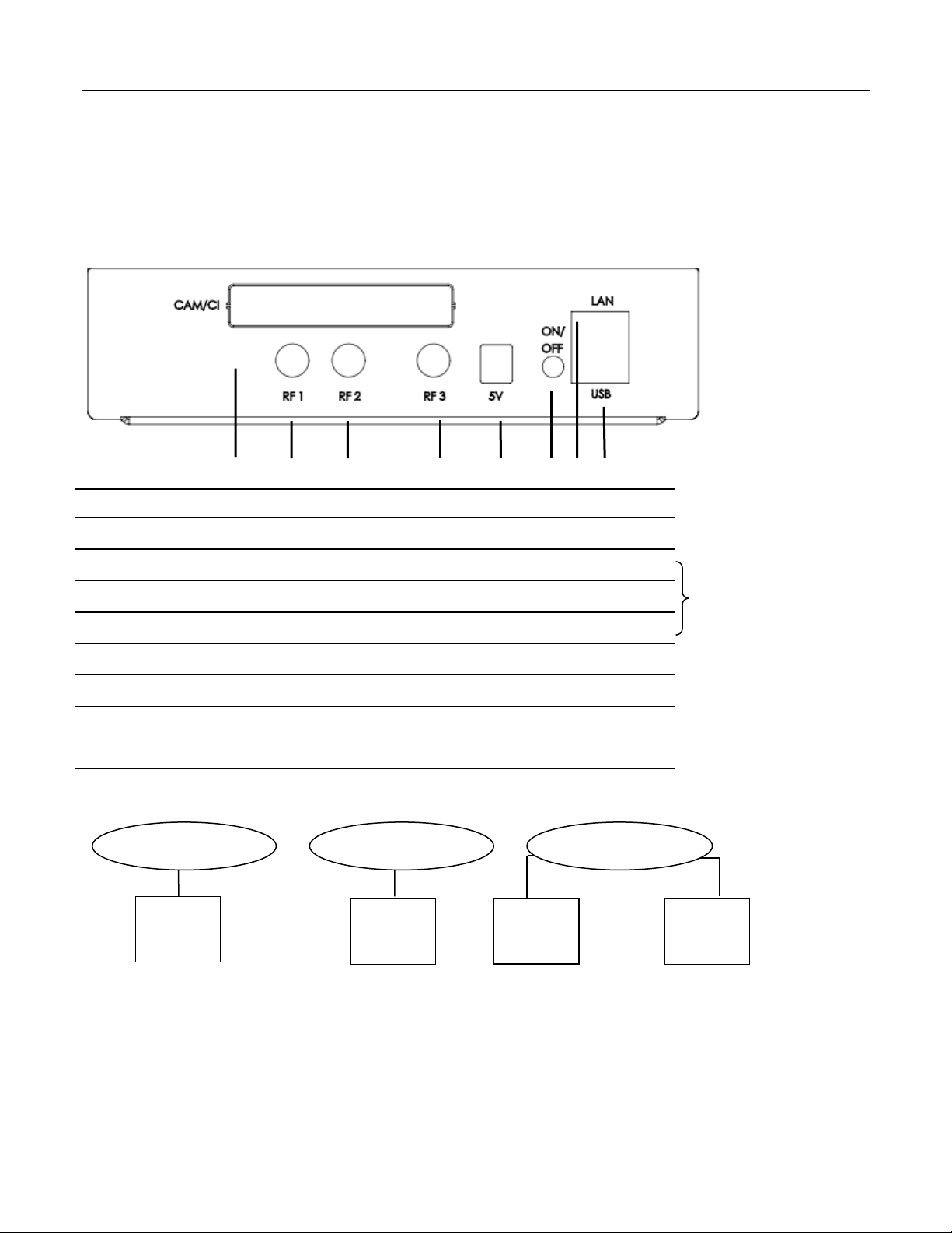
2.3.2 XTi-3340-50 CI Rear Panel
The rear panel includes two satellite tuners and two DVB-T or two DVB-C tuners (see Figure 4).
(See How to switch between DVB-T and DVB-C Configuration in Paragraph 14.1)
Figure 4: XTi 3342-52 / 3340-50 /CI – Rear Panel
Diagram 2: XT1 XTi 3342-52 / 3340-50 /CI Connectors and Tuners
DVBS
7

VBox V@Home TV Gateway User Manual 2. Front and Rear Panels
Item
Description
1
RF3– Connector for 2* Tuner (DVB-T//C)
(See diagram 3 below)
2
5V–power adapter connector
3
ON/OFF– Power button
4
LAN– RJ45 100 Mb (Ethernet cable) connector
5
USB – USB Connector
6
CAM/CI– Optional CI slot for DVB-T/C
Tuner 2
DVB-T/C
Tuner 1
DVB-T/C
RF3 Connector
4
5
1
2
6
3
0. (See How to switch between DVB-T and DVB-C Configuration in Paragraph 14.1)
2.3.3 XTi-3342-52 CI Rear Panel
XTi-3342-52 Dual Tuner 2T/2C has a rear panel with a single connector (RF3) for either two DVB-T/T2 tuners or
two DVB-C tuners (Figure 5). (See How to switch between DVB-T/T2 and DVB-C Configuration Paragraph 14.1)
Figure 5: XTi 3342CI Dual Tuner (Terrestrial or Cable) – Rear Panel
Diagram 3: XT1 3342 - Dual Tuner 2T/2C: Single Connector for Two DVB-T/T2 or DVB-C Tuners
8

VBox V@Home TV Gateway User Manual 2. Front and Rear Panels
Item
Description
1
RF3– Connector for 2* Tuner (DVB-T//C)
(See diagram 3 below)
2
12V– power adapter connector
3
ON/OFF – Power button
4
LAN – RJ45 100 Mb (Ethernet cable) connector
5
USB – USB Connector
Tuner 2
DVB-T/C
Tuner 1
DVB-T/C
RF3 Connector
4
5
1
2
3
0. (See How to switch between DVB-T and DVB-C Configuration in Paragraph 14.1)
2.3.4 XTi-3442-52 Rear Panel
XTi-3442-52 Dual Tuner 2T/2C has a rear panel with a single connector (RF3) for either two DVB-T/T2 tuners or
two DVB-C tuners (Figure 5). (See How to switch between DVB-T/T2 and DVB-C Configuration Paragraph 14.1)
Figure 6: XTi 3442 Dual Tuner (Terrestrial or Cable) – Rear Panel
Diagram 4: XT1 3442 - Dual Tuner 2T/2C: Single Connector for Two DVB-T/T2 or DVB-C Tuners
9

VBox V@Home TV Gateway User Manual 3. Connecting XTi-VBox TV Gateway to your Home Network
3.1. Package Contents
3 Connecting XTi-VBox TV Gateway to your Home Network
3.1 Package Contents
Your package includes the following items:
The XTi-VBox TV Gateway device you have chosen
An AC power cable
A Ethernet Cable-CAT5
3.2 Additional Required Equipment
To install and use XTi-VBox TV Gateway, you need the following additional items:
Satellite dish + coaxial cable with “F” type male connector to connect the device to the satellite
Terrestrial antenna + coaxial cable with “F” type male connector to connect the device to the
terrestrial or cable input
Interface device: Android Tablet (running Android 5 or higher), iPad (running iOS 6 or higher),
laptop, PC or Mac
Apps :VBox apps available for free from Apple Apps Store or Android Play or any UPnP app.
Network router Wireless broadband router-N or higher
3.3 Installing the XTi-VBox TV Gateway Device
To install your device, take the following steps:
1. Connect the Ethernet cable to the network router and to the XTi device’s LAN connector.
2. Connect the coaxial cable running from the satellite dish to the XTi device’s satellite RF-In connector.
3. Connect the coaxial cable running from the terrestrial antenna to the XTi device’s terrestrial RF-In
connector.
4. Connect the 12-DC power adapter to the XTi device and to the mains.
3.4 Configure the XTi-VBox TV Gateway using Tablet / iPad
1. Download the VBox Live TV free application for iOS or Android
2. Make sure that the tablet is connected to the same network as the XTi-VBox TV Gateway
3. Launch the application and wait until the application finds the XTi-VBox TV Gateway
4. The application will prompt to configure the device, press OK and follow the quick setup wizard
10

VBox V@Home TV Gateway User Manual 4. Configuring your Router and PC to Use the UPnP Protocol
4.1. Accessing XTi-VBox TV Gateway on PC using “My Network Places”
4 Configuring your Router and PC to Use the UPnP Protocol
To configure the XTi-VBox TV Gateway device using software, you are first required to enable the UPnP protocol.
UPnP automatically discovers all network devices and adds the XTi device to “My Network Places”.
Proceed as follows:
1. On your router – make sure UPnP is enabled (this is the default setting).
2. On your PC – check if UPnP is enabled. If UPnP is disabled, enable it now as follows:
Windows XP – see How to enable the Universal Plug and Play (UPnP) in Windows XP ...
Windows Vista and up – UPnP is enabled by default: Enable or disable network discovery
Once UPnP is enabled, you can access your XTi device using “My Network Places”, as explained in the
following section.
4.1 Accessing XTi-VBox TV Gateway on PC using “My Network Places”
1. Make sure your PC is connected to a router.
2. Connect the router to the XTi device using an Ethernet cable.
3. Turn on the XTi device by pressing the ON/OFF button on its front panel (Figure 1 on page 4).
The ON/OFF LED turns orange, indicating that the device is in the process of loading.
When the ON/OFF LED turns green, the XTi device is ready: it is automatically assigned an IP address and is
recognized by the router.
4. Access the XTi device using “My Network Places”:
Windows XP – go to My Network Places (Figure 7), display the network devices list and click
VBox TV Gateway (vbox_xxxx).
Figure 7: Windows XP – My Network Places showing VBox TV Gateway
11

VBox V@Home TV Gateway User Manual 4. Configuring your Router and PC to Use the UPnP Protocol
NOTE: The XTi device’s default name is VBox TV Gateway (vbox_xxxx), where “xxxx” is the product’s
number. This name appears on devices that are connected to your network and have the UPnP
Protocol enabled. When Setting up XTi-VBox TV Gateway using the Web Interface as explained in the
next section, you have the option to rename this device (using the System Name property).
4.1. Accessing XTi-VBox TV Gateway on PC using “My Network Places”
Windows 7 – go to Network > Media Devices (Figure 8), right click VBox TV Gateway (xbox_xxxx)
and select View device webpage from the context menu.
Figure 8: Windows 7 – Network Media Devices showing VBox TV Gateway
12

VBox V@Home TV Gateway User Manual 4. Configuring your Router and PC to Use the UPnP Protocol
4.2. Accessing XTi-VBox TV Gateway from Mac OS X
4.2 Accessing XTi-VBox TV Gateway from Mac OS X
1. Make sure you have VLC web plugin installed – The web plugin is a separate VLC packaged and
not part of the VLC player -
http://nightlies.videolan.org/build/macosx-intel/
2. To configure the TV Gateway – Open Safari and type your TV Gateway's IP address
- for example: http://192.168.0.100
2. To view Live TV - Open Safari and type your TV Gateway's IP address/liveTV
- for example: http://192.168.0.100/liveTV
3. Save the page in your bookmark
The XTi-VBox TV Gateway Web interface is displayed, showing its Welcome page (Figure 9).
Figure 9: VBox TV Gateway interface – Welcome page
The following section explains how to use this Web interface to easily set up your device.
13

VBox V@Home TV Gateway User Manual 5. Setting up XTi-VBox TV Gateway using the Web Interface
NOTE: You can later customize this quick setup, by re-launching the interface and clicking Manage.
Quick Setup
Steps
5.1. Step 1 – System Setup
5 Setting up XTi-VBox TV Gateway using the Web Interface
When configuring your XTi device for the first time, it is recommended to choose the Quick Setup option
(Figure 9 on page 13).
The Quick Setup Wizard is displayed, guiding you through the steps listed on the left panel (Figure 10).
In this section:
Step 1 – System Setup (page 14)
Step 2 – Tuners Setup (page 17)
Step 3 – Scan (page 23 )
Step 4 – Channels Setup (page 28)
5.1 Step 1 – System Setup
Step 1- System Setup requires that you first select your Device Configuration (Figure 10).
Figure 10: Quick Setup Wizard – Step 1 – System Setup: Device Configuration page
1. Set your device to use one of the following configurations:
VBox TV Gateway – sets your device to use the VBox TV Gateway configuration.
14

VBox V@Home TV Gateway User Manual 5. Setting up XTi-VBox TV Gateway using the Web Interface
Option
Description
Interface Language
and Device Name
Set this Web interface’s langauge and name your device.
SystemLanguage
Select the language of this Web interface from the list.
SystemName
The name of your XTi-VBox TV Gateway device.
This name appears on devices that are connected to your network and
have the UPnP Protocol enabled, for example: your PC’s Network
Places (see Figure 7on page 11 and Figure 8 on page 12).
Use the default name or override it by entering a new name.
Local Time Settings
Determine your device’s date and time settings.
TimeZone
Select your time zone from the list.
NOTE: You can move back and forth through the Quick Setup Wizard by clicking the following buttons:
Next – saves the settings of the current page and continues to the next step.
Back – discards the settings of the current page and returns to the previous step.
Start Over – discards all your settings and restarts the Wizard.
5.1. Step 1 – System Setup
2. Click Next. The System Settings page is displayed (Figure 11).
Figure 11: Quick Setup Wizard – Step 1 – System Setup: System Settings page
3. Configure your system settings as explained in Table 4.
Table 4: Quick Setup Wizard – Step 1 – System Setup: System Settings page
15

VBox V@Home TV Gateway User Manual 5. Setting up XTi-VBox TV Gateway using the Web Interface
Option
Description
Preferred Prioritized
Audio Languages
Select the language in which you prefer to recieve audio media.
You can list up to three languagesin the order of preference. Your device
will perform the search in the specified order, and provide the audio in
the first requested language that is available in the stream.
If you do not set these preferences, or if these languages are not
available, the device will provide the stream’s default audio language.
Preferred Prioritized Guide
& Subtitles Languages
Select the language in which you prefer to view program guides and
subtitles.
PreferredGuide(EPG)
Language
Select the language in which you prefer to view your electronic
programguide (EPG).
EnableSubtitles
Check this box to display subtitles and select their preferred language.
5.1. Step 1 – System Setup
4. Click Next. The Streaming Settings page is displayed (Figure 12).
Figure 12: Quick Setup Wizard – Step 1 – System Setup: Streaming Settings page
5. Configure your streaming settings as explained in Table 5:
Table 5: Quick Setup Wizard – Step 1 – System Setup: Streaming Settings page
These settings complete Step 1-System Setup and you can proceed to Step 2 – Tuners Setup.
16

VBox V@Home TV Gateway User Manual 5. Setting up XTi-VBox TV Gateway using the Web Interface
NOTE: Step 2 – Tuners Setup includes different options, depending on your XTi-VBox TV Gateway
product. Make sure you follow the instructions pertaining to your product and model.
5.2. Step 2 – Tuners Setup
5.2 Step 2 – Tuners Setup
In this section:
Step 2 – Tuners Setup for XTi 3332 Dual Tuner (page 18)
Step 2 – Tuners Setup for XTi 3340 (page 21)
17

VBox V@Home TV Gateway User Manual 5. Setting up XTi-VBox TV Gateway using the Web Interface
5.2. Step 2 – Tuners Setup
5.2.1 Step 2 – Tuners Setup for XTi 3332 Dual Tuner
1. Click Next. The Step 2 – Tuners Setup: Tuner 1 page for XTi-3332 Dual Tuner is displayed
(Figure 13).
Figure 13: Quick Setup Wizard– Step 2 – Tuners Setup: Tuner 1 page (XTi-3332 Dual Tuner)
18

VBox V@Home TV Gateway User Manual 5. Setting up XTi-VBox TV Gateway using the Web Interface
Option
Description
Tuner Activation
You may choose to connect only one tuner to a satellite dish.
In this case, you are required to disable the disconnected tuner, otherwsie the
Scan operation will fail for this tuner (as explained in Step 3 – Scan on page 23).
DisableTuner
Disables the specified tuner. If you have a tuner that is not connected to a
satellite, disable it by checking this option.
NOTE: When you disable the tuner, all tuner settings are hidden and a warning is
displayed, clarifying that this tuner will not be used.
LNB Settings
Configure your Low Noise Block (LNB) downconverter settings.
LNB is the satellite’s receiving device, which collects the radio waves from the
dish. LNB recieves a very weak signal, so it has to be amplify it before
downconversion. The LNB options determine how to amplify the signal while
adding the minimum possible amount of noise .
Either keep the default XTI LNB settings, or override them with your preferences.
Type
Choose the LNB type from the list. This selection deterimes the LNB options you
can configure. Bydefault, XTi uses the Ku-Band Universal LNB, with the options
shown in Figure 13.
Low
Enter the low band reception. XTi is set to the default value of your LNB type.
High
Enter the high band reception. XTi is set to the default value of your LNB type.
Satellite Selection
Select a satellite and transponders whose broadcasting you wish to receive.
Selectsatellite
Select a satellite from the drop-down list.
Applythesame
satellitesettingson
othertuners
If more than one tuner is connected to the same satellite dish, these tuners must
have the same satellite and transponder settings (otherwise, the information will
be duplicated).
select this option to apply the satellite settings of Tuner 1 to other tuners
connected to the same dish (in this case, Tuner 2).
Tuner(number)
Select additional tuners to which you wish to apply these satellite and
transponder settings .
You must make sure that the selected tuners are connected with a cable to the
same satellite dish.
NOTE: Since some satellites may have numerous transponders, the Transponders list may be very long.
For your convenience, the Back, Start Over and Next buttons appear both above and below the list.
Transponders List
Displays all transponders available for the selected satellite.
SelectTransponders
forScanning
Check the boxes of the transponders to be used to scan this satellite.
To select all transponders on the list, check the top box.
To add your own transponder, enter its settings into the bottom row.
Numberofselected
transponders
Shows the number of transponders you have selected.
5.2. Step 2 – Tuners Setup
2. Configure your tuner settings as explained in Table 6:
Table 6: Quick Setup Wizard – Step 2 – Tuners Setup: Tuner 1 page (XTi-3332 Dual Tuner)
19

VBox V@Home TV Gateway User Manual 5. Setting up XTi-VBox TV Gateway using the Web Interface
Option
Description
RF Feeding
Indicates that the satellite and transponder settings of another tuner (in this
case, Tuner 1) have been applied to Tuner 2.
CurrentTunerRFfeed
sharedwith[Tuner#]
Shows the name of the tuner whose satellite settings have been applied to
Tuner 2.
Removesatelliteand
transpondersettings
Select this option remove the satellite and transponder settings and to configure
them manually for Tuner 2 (see Table 6: Quick Setup Wizard – Step 2 – Tuners
Setup: Tuner 1 page (XTi-3332 Dual Tuner) on page 19 ).
LNB Settings
Shows the LNB settings of Tuner 1 (see Table 6).
Satellite Selection
Shows the satellite selected for Tuner 1 (see Table 6).
5.2. Step 2 – Tuners Setup
3. Click Next. The Step 2 – Tuners Setup: Tuner 2 page for XTi-3332 Dual Tuner is displayed
(Figure 14).
Figure 14: Quick Setup Wizard– Step 2 – Tuners Setup: Tuner 2 page (XTi-3332 Dual Tuner)
4. Configure the settings of Tuner 2 as explained in Table 7:
Table 7: Quick Setup Wizard – Step 2 – Tuners Setup: Tuner 2 page (XTi-3332 Dual Tuner)
These settings complete Step 2-Tuners Setup and you can proceed to Step 3 – Scan.
20

VBox V@Home TV Gateway User Manual 5. Setting up XTi-VBox TV Gateway using the Web Interface
5.2. Step 2 – Tuners Setup
5.2.2 Step 2 – Tuners Setup for XTi 3340/3442/3350/3452 Models
XTi-VBox Combi models include four tuners:
Tuners 1 and 2 are intended for satellite broadcasting (DVB-S)
Tuners 3 and 4 intended for either terrestrial broadcasting (DVB-T), or cable broadcasting (DVB-C).
Set up the four tuners as follows:
1. Set up Tuner 1 and Tuner 2 as explained in Step 2 – Tuners Setup for XTi 3332 Dual Tuner (page 18).
2. Click Next. The Step 2 – Tuners Setup: Tuner 3 + 4: page is displayed (Figure 15).
Figure 15: Quick Setup Wizard – Step 2 – Tuners Setup: Tuners 3 + 4 page (XTi-334X/5X)
21

VBox V@Home TV Gateway User Manual 5. Setting up XTi-VBox TV Gateway using the Web Interface
Option
Description
Tuner Activation
You may choose not to connect Tuner 3 and Tuner 4 to a terrestrial antena.
In this case, you are required to disable the disconnected tuners, otherwsie their
Scan operation will fail (as explained in Step 3 – Scan on page 23).
DisableTuner
Disables Tuner 3 and Tuner 4. Choose this option if these tuners are not
connected to a terrestrial antena.
NOTE: When you disable these tuners, all tuner settings are hidden and a
warning is displayed, clarifying that these tuners will not be used.
Country Selection
Select your country in order to filter the channels list by your location.
NOTE: Since the channels list may be very long, the Back, Start Over and Next buttons appear both above
and below the list.
Channels Table
Displays all channels available for the selected terrestrial antena.
Pleaseselectchannels
forscanning
Check the boxes of the channels to be used to scan this terrestrial antena.
To select all channels on the list, check the top box.
To add your own channel to the list, enter its definitions into the
bottom row.
Numberofselected
channels
Shows the number of channels you have selected.
5.2. Step 2 – Tuners Setup
3. Setup Tuner 3 and Tuner 4 as explained in Table 8:
Table 8: Quick Setup Wizard – Step 2 – Tuners Setup: Tuner 3 + 4 page (XTi-3340/3342)
These settings complete Step 2-Tuners Setup and you can proceed to Step 3 – Scan.
22
 Loading...