

Page 1

COMPETITION GRADE HIGH PERFORMANCE RADIO CONTROL RACING CAR CHASSIS KIT
1/10 4WD ELECTRIC COMPETITION TOURING CAR KIT
E
INSTRUCTIONS MANUAL
5
Thank you for purchasing VBC Racing product.
This VBC Racing kit is a high performance, racing grade car kit
intended for experienced racers. The kit compose of VBC
formulated composite materials, top quality FRP chassis and
high grade 7075 material which will give you a competitive edge
over the others.
Novice racer should seek advice from more experienced racer
before assembly.
Always keep this instruction manual handy at all times for quick
reference even after completing the assembly.
Before your assembly, sand the chassis edges.
Things that we should remind you.
Sand the chassis edges with #600 sand paper and apply CA
glue to the edges and counter sink holes.
Need help or support.
If you need help or you would like to leave us a comment,
please email to our support team: support@vbc-racing.com or
visit our web site www.vbcracing.com
All manuals and user guides at all-guides.com
all-guides.com
Page 2

BAG MARKED
STEP1
Front Lower Bulkhead Assembly
01
© VBC Racing GHOST EVO
Ghost Evo Lower Bulkhead B-02-P40293 x 4
M3x6 Flathead C-02-SC-F0306 x 14
M3x6 Flathead
M3x6 Flathead
M3x6 Flathead
M3x6 Flathead
Lower Bulkhead
Lower Bulkhead
Ghost Evo Motor Mount B-02-P40296 x 1
Ghost Evo Center Pully Bulkhead B-02-P40297 x 2
Ghost Evo Motor Mount Support B-02-P40307 x 1
Motor Mount
Center Pully Bulkhead
Motor Mount Support
Center Pully Bulkhead
Lower Bulkhead
Lower Bulkhead
M3x6 Flathead
M3x6 Flathead
M3x6 Flathead
M3x6 Flathead
M3x6 Flathead
M3x6 Flathead
M3x6 Flathead
M3x6 Flathead
M3x6 Flathead
M3x6 Flathead
A-01-P-40305 GhostEVO Main Chassis
Optional Graphite Chassis
A-01-G-40540 GhostEVO Graphite Main Chassis
or D-05-VBC-0191 GhostEVO Full Graphite Conversion
M3x10mm Round Head Screw C-02-SC-R0310 x 2
M3x10mm Round Head Screw
M3x10mm Round Head Screw
All manuals and user guides at all-guides.com
Page 3

38
BAG MARKED
STEP2-3
2
Rear Gear Diff Assembly
Rear Gear Diff Left Side
Rear Gear Diff Right Side
Gear Diff Housing A-03-VBC-0016 x 1
Gear Diff Pulley 38T A-03-VBC-0017 x 1
Diff Gear 18T A-03-VBC-0019 x 2
Diff Cup B-02-VBC-0022 x 2
10x15 Ball Bearing C-02-BB-1510-P x 2
M2x10 Shaft Pin B-02-VBC-0020 x 2
15x0.3 Shim B-02-VBC-0077 x 2
Diff Shaft Sealer O-Ring B-03-VBC-0006 x 2
Rear Gear Diff Right Side Assembly Cross Section
Diff Gear 18T
Diff Outdrive
Right Gear
Diff Housing
02
Diff Ourdrive
© VBC Racing GHOST EVO
Gear Diff Pulley 38T
Diff Gear 18T
10x15 Ball Bearing
15x0.3 Shim
M2x10 Shaft Pin
Outdrive Sealer O-Ring
Outdrive Sealer O-Ring
10x15 Ball Bearing
M2x10 Shaft Pin
Diff Oil
Apply small amount of diff oil
Diff Outdrive
Diff Gear 18T
Right Gear Diff Housing
10x15 Ball Bearing
15x0.3 Shim
M2x10 Shaft Pin
Outdrive Sealer O-Ring
Diff Oil
Apply small amount of diff oil
15x0.3 Shim
All manuals and user guides at all-guides.com
Page 4

3
Rear Gear Diff Assembly Continue
Diff Gear 10T A-03-VBC-0018 x 4
M2.6x10 Flathead Screw C-02-SC-F2.6x10 x 4
Seal Gasket B-03-VBC-0004 x 1
03© VBC Racing GHOST EVO
9.5x0.2mm Shim B-02-VBC-0078 x 4
Belt Tension Adjuster Ring A-03-VBC-0047 x 2
Idle Gear 10T
Idle Gear 10T
Idle Gear 10T
Idle Gear 10T
Right Side Diff
Right Side Diff Assembly
Left Side Diff Assembly
Belt Tension Adjuster Ring
Belt Tension Adjuster Ring
STEP2-3
Fill with supplied DIFF TYPE silicon oil
until the gears are fully submerged
9.5x0.2mm Shim
9.5x0.2mm Shim
9.5x0.2mm Shim
9.5x0.2mm Shim
Diff Gear Shaft A-03-VBC-0020 x 1
Diff Gear Shaft
Diff Housing Sealer O-Ring
Seal Gasket
M2.6x10 Flathead Screw
Place Seal Gasket
to the left side diff
assembly before
putting the right
side diff together
Diff Oil
Diff Housing Sealer O-Ring B-03-VBC-0005 x 1
BAG MARKED
Grease
All manuals and user guides at all-guides.com
Page 5

BAG MARKED
STEP4
4
Front Drive Train Assembly - Spool Assembly
04
© VBC Racing GHOST EVO
Front Spool 38T A-03-VBC-0021 x 1
Pulley Belt Guide A-03-VBC-0022 x 1
Spool Drive Shaft A-03-VBC-0049 x 1
Front Spool Outdrive A-03-VBC-0055 x 2
Belt Tension Adjuster Ring A-03-VBC-0047x 2
10x15 Ball Bearing C-02-BB-1510-P x 2
M3x12 Flathead C-02-SC-F0312 x 2
M3x6 Roundhead C-02-SC-R0306 x 3
M3x12 Flathead
Spool Drive Cup
Diff Holder
10x15 Ball Bearing
M3x6 Roundhead
M3x6 Roundhead
M3x6 Roundhead
Front Spool 38T
Pulley Guide
Spool Shaft
10x15 Ball Bearing
Diff Holder
Spool Drive Cup
M3x12 Flathead
Apply CA and note the position
Optional: 7075 Aluminum Spool Shaft B-02-VBC-0094 (not included)
Optional :
Lightweight Hardened Spool Outdrive
A-03-VBC-0106
All manuals and user guides at all-guides.com
Page 6

BAG MARKED
STEP5-7
5
Install Front Drivetrain
05© VBC Racing GHOST EVO
B-03-VBC-3045 Front Belt 510mm
6
Steering System Assembly
Composite Steering Arms A-03-VBC-4002 x 2
3x6 Ball Bearing C-02-BB-0603 x 2
5x8 Ball Bearing C-02-BB-0805-B x 4
Steering Assembly Pole B-02-VBC-0055 x 2
Ball Connector B-02-VBC-0045 x 3
M3x6 Roundhead C-02-SC-R0306 x 2
M3 x 0.2 Shims B-02-VBC-0100 X 4
M3x8 Roundhead C-02-SC-R0308 x 2
M3x6 Set Screw C-02-SC-SS-0306 x 1
Thread Lock
Composite Steering Arms
Composite Steering Arms
5x8 Ball Bearing
5x8 Ball Bearing
5x8 Ball Bearing
5x8 Ball Bearing
M3 x 0.2 Shims
M3 x 0.2 Shims
M3 x 0.2 Shims
M3 x 0.2 Shims
M3x6 Roundhead
M3x6 Roundhead
Steering Assembly Pole
Steering Assembly Pole
Ball Connector 4.7x12mm A-02-VBC-5015 x 2
Ball Connector 4.7x12mm
Ball Connector 4.7x12mm
Suspension Arm Spacer T2 (Composite) A-03-VBC-0052 x 2
Suspension Arm Spacer T2
Ghost Evo Steering Bridge B-02-P40324 x 1
M3x8 Roundhead
M3x8 Roundhead
Ball Connector
M3x6 Set Screw
3x6 Ball Bearing
3x6 Ball Bearing
All manuals and user guides at all-guides.com
all-guides.com
Page 7

BAG MARKED
STEP5-7
7
Steering System Assembly
© VBC Racing GHOST EVO
7.50mm
29.40mm
M3x42mm Turnbuckle B-02-VBC-0037 x 2
M3x18mm Turnbuckle B-02-VBC-0038 x 1
Turnbuckle Cup A-03-VBC-0039 x 4
Make 2 steering link tie-rods, follow the connector cups directions as
the above diagram. The connector cups edge to edge shall be 29.40mm.
Please use a caliper to measure the exact measurement
Make 1 servo link tie-rod, follow the connector cups directions as
the above diagram. The connector cups edge to edge shall be 7.50mm.
Please use a caliper to measure the exact measurement
M3x42mm Turnbuckle
Turnbuckle Cup
Turnbuckle Cup
Turnbuckle Cup
M3x18mm Turnbuckle
Right Thread
Right Thread
Right Thread
06
06
Turnbuckle Cup (Long) A-03-VBC-5016 x 2
Turnbuckle Cup (Long)
M3x6 Flathead C-02-SC-F0306 x 2
M3x6 Flathead
M3x6 Flathead
All manuals and user guides at all-guides.com
Page 8

BAG MARKED
STEP8-12
8
Upper Deck Assembly
07
© VBC Racing GHOST EVO
Belt Tensioner B-02-VBC-3003 x 1
3x6mm Ball Bearing C-02-BB-0603 x 2
3x5x0.3mm Shim B-02-VBC-0101 x 3
M3x12 Roundhead Screw C-02-SC-R-0312 x 1
M3x6 Roundhead Screw C-02-SC-R0306 x 1
20T Center Pulley A-03-VBC-0023 x 2
Center Pulley Spacer A-03-VBC-0060 x 1
Center Pulley Drive Shaft B-02-VBC-0087 x 1
5x8mm Ball Bearing C-02-BB-0805-B x 2
M3x4 Round Head Screw
C-02-SC-R0304 x 3
M3x6 Set Screw x 2
C-02-SC-SS-0306
M2x12 Shaft Pin B-02-VBC-0020-12 x 2
M5x11 E-Clip B-02-VBC-0085 x 2
9
M3x12 Roundhead
3x6mm Ball Bearing
3x5x0.3mm Shim
3x6mm Ball Bearing
3x5x0.3mm Shim
Belt Tensioner
M3 Lock Nut C-02-SC-NN03 x 1
5x8mm Ball Bearing
M5x11 E-Clip
20T Center Pulley
Center Pulley Drive Shaft
M2x12 Shaft Pin
Center Pulley Spacer
M2x12 Shaft Pin
M3x4 Roundhead
M5x11 E-Clip
5x8mm Ball Bearing
M3x6 Set Screw
M3x6 Set Screw
Spur Gear
3x5x0.3mm Shim
M3x6 Roundhead
Loosen The Screw To
Adjust Belt Tension
A-03-VBC-4017 64P Spur Gear 96T
GHOST EVO Upper Deck A-01-P40306
Optional Graphite Upper Deck
A-01-G-40539 GhostEVO Mid Flex Graphite Upper Deck or
A-01-G-40546 GhostEVO High Flex 1.6 Graphite Upper Deck
or D-05-VBC-0191 GhostEVO Full Graphite Conversion
All manuals and user guides at all-guides.com
Page 9

BAG MARKED
STEP8-12
10 -12
Upper Deck Assembly
08
© VBC Racing GHOST EVO
M3x6 Roundhead C-02-SC-R0306 x 9
M3x6 Flathead C-02-SC-F0306 x 2
Center Pulley Bearing Holder B-02-VBC-3020 x 2
Ghost Evo Rear Belt B-03-G30288 x 1
M3x6 Roundhead
M3x6 Roundhead
M3x6 Roundhead
M3x6 Flathead
M3x6 Flathead
Center Pulley Bearing Holder
Center Pulley Bearing Holder
All manuals and user guides at all-guides.com
Page 10

BAG MARKED
STEP13-15
13
09
© VBC Racing GHOST EVO
Suspension Arm Spacer T2 (Composite) A-03-VBC-0052 x 4
14
Upper Bulkhead Assembly
MAKE FOUR
Ball Connector B-02-VBC-0045 x 4
M3x6 Set Screw C-02-SC-SS-0306 x 4
Ghost Evo Upper Bulkhead B-02-P40294 x 4
Ball Connector
Suspension Arm Spacer T2
M3x6 Set Screw
Ghost Evo Upper Bulkhead
Thread Lock
R00 Center Rear Linked Suspension Mount B-02-P40316 x 1
M3x6 Flathead C-02-SC-F0306 x 2
M2x4 Roundhead C-02-SC-R0204 x 2
M3x8 Roundhead C-02-SC-R0308 x 4
M3x8 Roundhead
M3x6 Flathead
M2x4 Roundhead
R00 Center Rear Linked Suspension Mount
D-05-VBC-0173 WildFireD07 Split Suspension Mount X/YC05
D-05-VBC-0174 WildFireD07 Split Suspension Mount X/YC10
D-05-VBC-0175 WildFireD07 Split Suspension Mount X/YC15
Optional WildFireD07 Split Mounts
Install Rear Drivetrain
Tighten screw to lock the Belt Tension Adjuster Ring position
Neutral
TightenLoosen
Tighten or loosen the belt tension by adjusting the Belt Tension Adjuster Ring dial
All manuals and user guides at all-guides.com
Page 11
BAG MARKED
STEP13-15
15
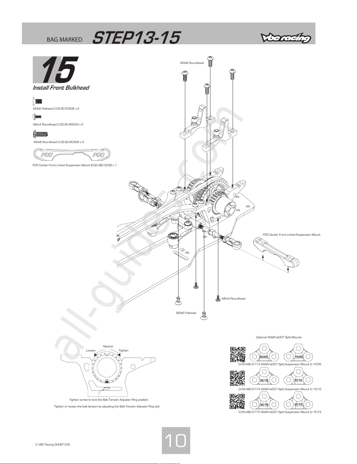
Install Front Bulkhead
10
© VBC Racing GHOST EVO
D-05-VBC-0173 WildFireD07 Split Suspension Mount X/YC05
D-05-VBC-0174 WildFireD07 Split Suspension Mount X/YC10
D-05-VBC-0175 WildFireD07 Split Suspension Mount X/YC15
Optional WildFireD07 Split Mounts
Tighten screw to lock the Belt Tension Adjuster Ring position
Neutral
TightenLoosen
Tighten or loosen the belt tension by adjusting the Belt Tension Adjuster Ring dial
M3x6 Flathead
M2x4 Roundhead
P00 Center Front Linked Suspension Mount
M3x6 Flathead C-02-SC-F0306 x 2
M2x4 Roundhead C-02-SC-R0204 x 2
M3x8 Roundhead C-02-SC-R0308 x 4
M3x8 Roundhead
P00 Center Front Linked Suspension Mount B-02-VBC-3039 x 1
All manuals and user guides at all-guides.com
all-guides.com
Page 12
BAG MARKED
STEP16-18
16
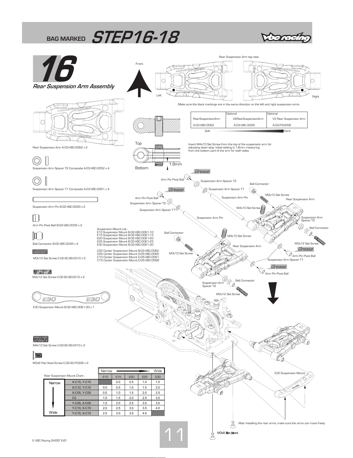
Rear Suspension Arm Assembly
11
© VBC Racing GHOST EVO
Rear Suspension Arm A-03-VBC-0062 x 2
Suspension Arm Spacer T2 Composite A-03-VBC-0052 x 4
Suspension Arm Spacer T1 Composite A-03-VBC-0051 x 4
Suspension Arm Pin B-02-VBC-0029 x 2
Ball Connector B-02-VBC-0045 x 4
Arm Pin Pivot Ball B-02-VBC-0035 x 2
M4x10 Set Screw C-02-SC-SS-0410 x 2
M3x10 Set Screw C-02-SC-SS-0310 x 2
E30 Suspension Mount B-02-VBC-0061-30 x 1
M3x6 Flat Head Screw C-02-SC-F0306 x 2
1.8mm
Bottom
Top
Left
Right
Front
Make sure the black markings are in the same direction on the left and right suspension arms
Insert M4x10 Set Screw from the top of the suspension arm for
adjusting down stop. Initial setting is 1.8mm measuring
from the bottom part of the arm for both sides.
Grease
Grease
Grease
Grease
After installing the rear arms, make sure the arms can move freely
Rear Suspension Arm
Rear Suspension Arm
M4x10 Set Screw
M4x10 Set Screw
Suspension Arm Pin
Suspension Arm Pin
Arm Pin Pivot Ball
Arm Pin Pivot Ball
Ball Connector
Ball Connector
M3x12 Set Screw
M3x12 Set Screw
Arm Pin Pivot Ball
Arm Pin Pivot Ball
Suspension Arm Spacer T2
Suspension Arm Spacer T2
Suspension Arm Spacer T1
Suspension Arm Spacer T1
Suspension Arm Spacer T1
Rear Suspension Arm top view
M3x6 Flat Head
E30 Suspension Mount
Suspension Mount List :
E10 Suspension Mount B-02-VBC-0061-10
E15 Suspension Mount B-02-VBC-0061-15
E20 Suspension Mount B-02-VBC-0061-20
E25 Suspension Mount B-02-VBC-0061-25
E30 Suspension Mount B-02-VBC-0061-30
C00 Center Suspension Mount B-02-VBC-0062
C05 Center Suspension Mount D-05-VBC-0065
C10 Center Suspension Mount D-05-VBC-0061
C15 Center Suspension Mount D-05-VBC-0068
Narrow Wide
E10 E15 E20 E25 E30
Narrow
X-C15, Y-C15 0.0 0.5 1.0 1.5
X-C10, Y-C10 0.0 0.5 1.0 1.5 2.0
X-C05, Y-C05 0.5 1.0 1.5 2.0 2.5
C0 1.0 1.5 2.0 2.5 3.0
Y-C05, X-C05 1.5 2.0 2.5 3.0 3.5
Y-C10, X-C10 2.0 2.5 3.0 3.5 4.0
Wide
Y-C15, X-C15 2.5 3.0 3.5 4.0
Rear Suspension Mount Chart :
Ball Connector
M3x10 Set Screw
M3x10 Set Screw
Ball Connector
Suspension Arm
Spacer T2
Suspension Arm
Spacer T2
M3x12 Set Screw C-02-SC-SS-0312 x 2
Soft Hard
V2 Rear Suspension Arm
A-03-VBC-3028
V3 Rear Suspension Arm
A-03-P30268
Rear Suspension Arm
A-03-VBC-0062
OptionalOptional
All manuals and user guides at all-guides.com
Page 13
BAG MARKED
STEP16-18
17
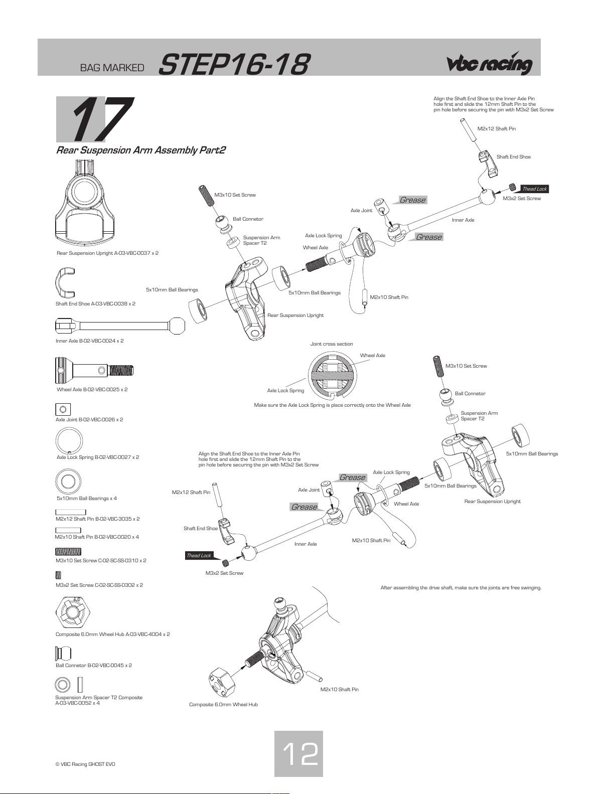
Rear Suspension Arm Assembly Part2
12
© VBC Racing GHOST EVO
Rear Suspension Upright A-03-VBC-0037 x 2
Shaft End Shoe A-03-VBC-0038 x 2
Inner Axle B-02-VBC-0024 x 2
Wheel Axle B-02-VBC-0025 x 2
Axle Joint B-02-VBC-0026 x 2
Axle Lock Spring B-02-VBC-0027 x 2
5x10mm Ball Bearings x 4
M2x12 Shaft Pin B-02-VBC-3035 x 2
M2x10 Shaft Pin B-02-VBC-0020 x 4
M3x10 Set Screw C-02-SC-SS-0310 x 2
M3x2 Set Screw C-02-SC-SS-0302 x 2
Composite 6.0mm Wheel Hub A-03-VBC-4004 x 2
Ball Connetor B-02-VBC-0045 x 2
Grease
Grease
Grease
Grease
Thead Lock
Thead Lock
After assembling the drive shaft, make sure the joints are free swinging.
Align the Shaft End Shoe to the Inner Axle Pin
hole first and slide the 12mm Shaft Pin to the
pin hole before securing the pin with M3x2 Set Screw
Align the Shaft End Shoe to the Inner Axle Pin
hole first and slide the 12mm Shaft Pin to the
pin hole before securing the pin with M3x2 Set Screw
Rear Suspension Upright
Rear Suspension Upright
Shaft End Shoe
Shaft End Shoe
M2x12 Shaft Pin
M2x12 Shaft Pin
Inner Axle
Inner Axle
Wheel Axle
Wheel Axle
Axle Joint
Axle Joint
Axle Lock Spring
Axle Lock Spring
M2x10 Shaft Pin
M2x10 Shaft Pin
5x10mm Ball Bearings
5x10mm Ball Bearings
5x10mm Ball Bearings
5x10mm Ball Bearings
M2x10 Shaft Pin
M3x2 Set Screw
M3x2 Set Screw
Ball Connetor
Ball Connetor
M3x10 Set Screw
M3x10 Set Screw
Axle Lock Spring
Wheel Axle
Make sure the Axle Lock Spring is place correctly onto the Wheel Axle
Joint cross section
Suspension Arm Spacer T2 Composite
A-03-VBC-0052 x 4
Suspension Arm
Spacer T2
Suspension Arm
Spacer T2
Composite 6.0mm Wheel Hub
All manuals and user guides at all-guides.com
Page 14
24mm
BAG MARKED
STEP16-18
18
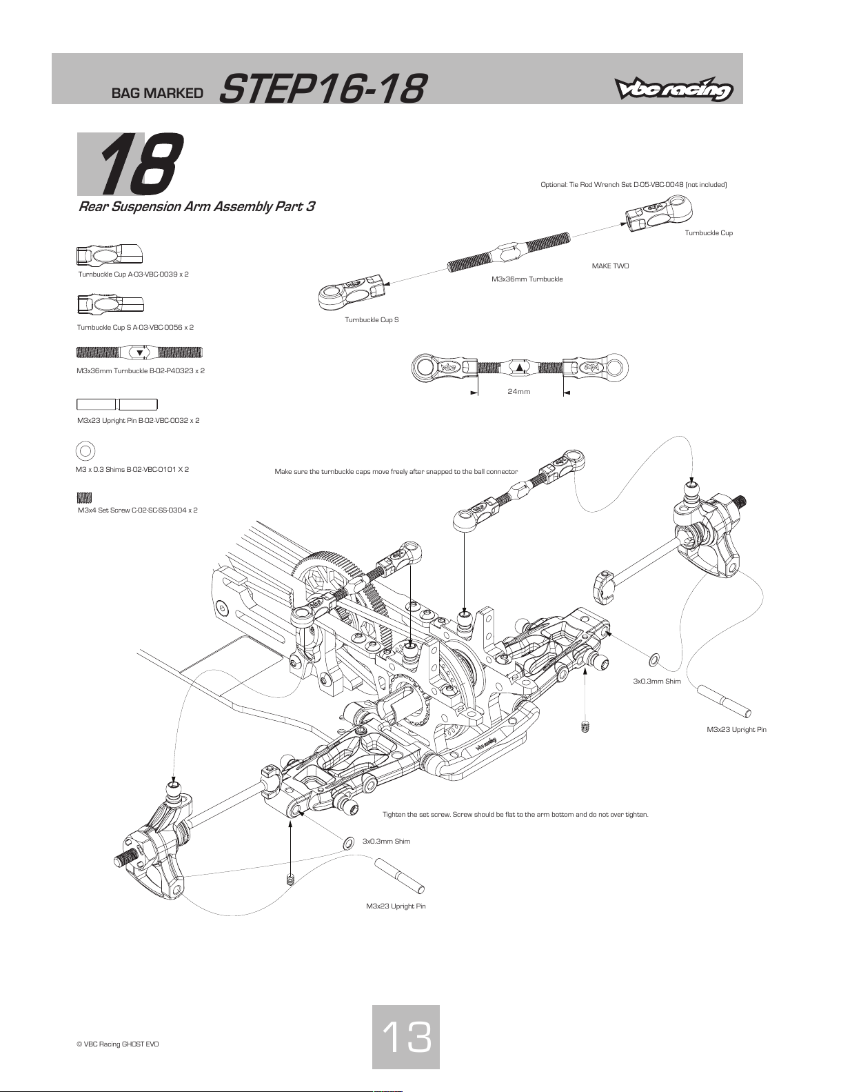
Rear Suspension Arm Assembly Part 3
13
© VBC Racing GHOST EVO
M3x36mm Turnbuckle B-02-P40323 x 2
M3x23 Upright Pin B-02-VBC-0032 x 2
M3x4 Set Screw C-02-SC-SS-0304 x 2
Make sure the turnbuckle caps move freely after snapped to the ball connector
Tighten the set screw. Screw should be flat to the arm bottom and do not over tighten.
Turnbuckle Cup S
Turnbuckle Cup
M3x36mm Turnbuckle
M3x23 Upright Pin
3x0.3mm Shim
Turnbuckle Cup A-03-VBC-0039 x 2
Turnbuckle Cup S A-03-VBC-0056 x 2
MAKE TWO
Optional: Tie Rod Wrench Set D-05-VBC-0048 (not included)
M3 x 0.3 Shims B-02-VBC-0101 X 2
3x0.3mm Shim
M3x23 Upright Pin
All manuals and user guides at all-guides.com
Page 15
BAG MARKED
STEP19-22
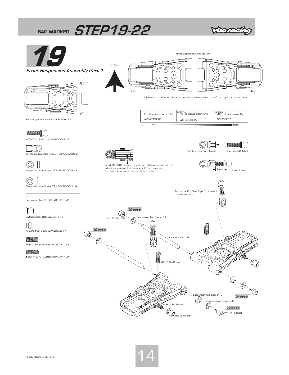
19
Front Suspension Assembly Part 1
14
© VBC Racing GHOST EVO
Front Suspension Arm A-03-VBC-0061 x 2
4.7x17mm Ballstud A-02-VBC-5092 x 2
Turnbuckle Cup Open Type S A-03-VBC-0040 x 2
Suspension Arm Spacer T2 A-03-VBC-0052 x 2
Suspension Arm Spacer T1 A-03-VBC-0051 x 4
Suspension Arm Pin B-02-VBC-0029 x 2
Ball Connector B-02-VBC-0045 x 4
Arm Pin Pivot Ball B-02-VBC-0035 x 4
M4x10 Set Screw C-02-SC-SS-0410 x 2
M3x10 Set Screw C-02-SC-SS-0310 x 2
Left Right
Front
Make sure the black markings are in the same direction on the left and right suspension arms
Insert M4x10 Set Screw from the top of the suspension arm for
adjusting down stop. Initial setting is 1.8mm measuring
from the bottom part of the arm for both sides.
Make 2 sets
Front Suspension Arms top view
Ball Connector Open Type S 4.7x17mm Ballstud
Suspension Arm Spacer T1
Arm Pin Pivot Ball
Suspension Arm Pin
M4x10 Set Screw
Suspension Arm Spacer T1
M3x10 Set Screw
Ball Connector
Suspension Arm Spacer T2
Arm Pin Pivot Ball
Grease
Grease
Grease
Grease
Turnbuckle Cup Open Type S connects to
the arm connector
1.8mm
7mm
Soft
Hard
V3 Front Suspension Arm
A03P30267
Front Suspension Arm (Soft)
A-03-VBC-0061
Optional Optional
V2 Front Suspension Arm
A-03-VBC-3027
All manuals and user guides at all-guides.com
Page 16
BAG MARKED
STEP19-22
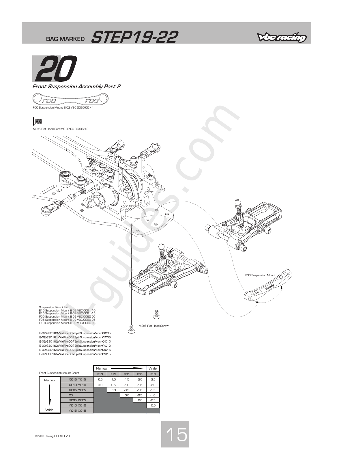
20
Front Suspension Assembly Part 2
15
© VBC Racing GHOST EVO
F00 Suspension Mount B-02-VBC-0060-00 x 1
M3x6 Flat Head Screw C-02-SC-F0306 x 2
Narrow Wide
E10 E15 F00 F05 F10
X-C15, Y-C15 -0.5 -1.0 -1.5 -2.0 -2.5
X-C10, Y-C10 0.0 -0.5 -1.0 -1.5 -2.0
X-C05, Y-C05 0.0 -0.5 -1.0 -1.5
C0 0.0 -0.5 -1.0
Y-C05, X-C05 0.0 -0.5
Y-C10, X-C10 0.0
Wide
Y-C15, X-C15
Narrow
Suspension Mount List :
E10 Suspension Mount B-02-VBC-0061-10
E15 Suspension Mount B-02-VBC-0061-15
F00 Suspension Mount B-02-VBC-0060-00
F05 Suspension Mount B-02-VBC-0060-05
F10 Suspension Mount B-02-VBC-0060-10
Front Suspension Mount Chart :
F00 Suspension Mount
M3x6 Flat Head Screw
All manuals and user guides at all-guides.com
all-guides.com
Page 17
Grease
BAG MARKED
STEP19-22
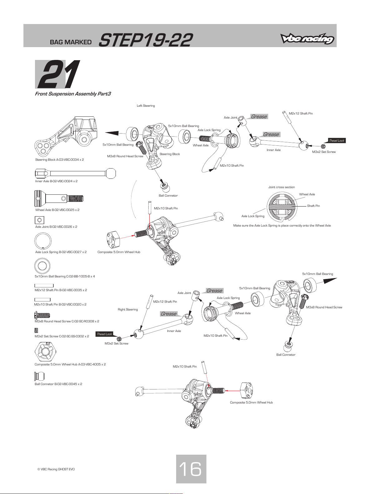
Front Suspension Assembly Part3
16
© VBC Racing GHOST EVO
Steering Block A-03-VBC-0034 x 2
Inner Axle B-02-VBC-0024 x 2
Wheel Axle B-02-VBC-0025 x 2
Axle Joint B-02-VBC-0026 x 2
Axle Lock Spring B-02-VBC-0027 x 2
M2x12 Shaft Pin B-02-VBC-0035 x 2
M2x10 Shaft Pin B-02-VBC-0020 x 2
M3x8 Round Head Screw C-02-SC-R0308 x 2
M3x2 Set Screw C-02-SC-SS-0302 x 2
Composite 5.0mm Wheel Hub A-03-VBC-4005 x 2
Ball Connetor B-02-VBC-0045 x 2
5x10mm Ball Bearing C-02-BB-1005-B x 4
Left Steering
Right Steering
Grease
Grease
Grease
Thead Lock
Thead Lock
Axle Lock Spring
Wheel Axle
Make sure the Axle Lock Spring is place correctly onto the Wheel Axle
Joint cross section
Shaft Pin
Steering Block
Inner Axle
Wheel Axle
Axle Joint
Axle Lock Spring
5x10mm Ball Bearing
5x10mm Ball Bearing
M3x2 Set Screw
M2x12 Shaft Pin
M2x10 Shaft Pin
M3x8 Round Head Screw
Composite 5.0mm Wheel Hub
Ball Connetor
5x10mm Ball Bearing
M3x8 Round Head Screw
Ball Connetor
5x10mm Ball Bearing
Wheel Axle
Axle Lock Spring
Axle Joint
Inner Axle
M2x12 Shaft Pin
M3x2 Set Screw
M2x10 Shaft Pin
Composite 5.0mm Wheel Hub
M2x10 Shaft Pin
M2x10 Shaft Pin
All manuals and user guides at all-guides.com
Page 18
Turnbuckle Cup A-03-VBC-0039W x 2
BAG MARKED
STEP19-22
22
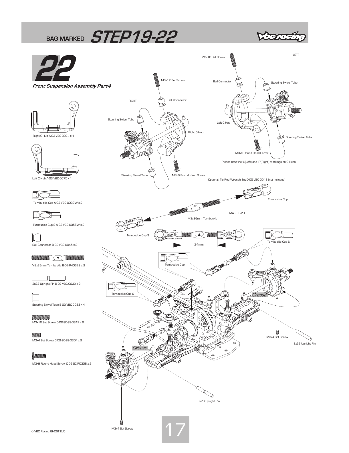
Front Suspension Assembly Part4
17
© VBC Racing GHOST EVO
Right C-Hub A-03-VBC-0074 x 1
Left C-Hub A-03-VBC-0075 x 1
Turnbuckle Cup S A-03-VBC-0056W x 2
M3x12 Set Screw C-02-SC-SS-0312 x 2
M3x4 Set Screw C-02-SC-SS-0304 x 2
3x23 Upright Pin B-02-VBC-0032 x 2
M3x9 Round Head Screw C-02-SC-R0308 x 2
Ball Connector B-02-VBC-0045 x 2
Steering Swivel Tube B-02-VBC-0033 x 4
Please note the 'L'(Left) and 'R'(Right) markings on C-Hubs
RIGHT
LEFT
Right C-Hub
Left C-Hub
Ball Connector
Ball Connector
3x23 Upright Pin
3x23 Upright Pin
M3x4 Set Screw
M3x4 Set Screw
Steering Swivel Tube
Steering Swivel Tube
Steering Swivel Tube
Steering Swivel Tube
M3x12 Set Screw
M3x12 Set Screw
M3x9 Round Head Screw
M3x9 Round Head Screw
Grease
Grease
Turnbuckle Cup S
Turnbuckle Cup S
M3x36mm Turnbuckle B-02-P40323 x 2
24mm
Turnbuckle Cup S
Turnbuckle Cup
M3x36mm Turnbuckle
MAKE TWO
Optional: Tie Rod Wrench Set D-05-VBC-0048 (not included)
Turnbuckle Cup
All manuals and user guides at all-guides.com
Page 19
BAG MARKED
STEP23-24
23
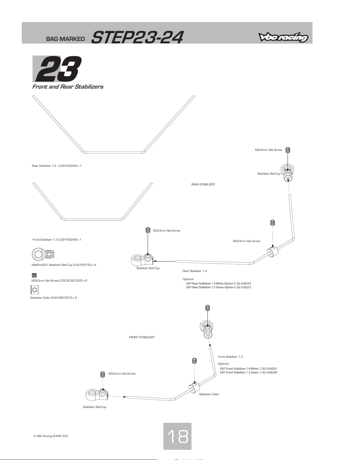
Front and Rear Stabilizers
18
© VBC Racing GHOST EVO
Rear Stabilizer 1.3 C-02-P30249 x 1
Front Stabilizer 1.3 C-02-P30248 x 1
WildFireD07 Stabilizer Ball Cup A-03-P30150 x 4
M3x3mm Set Screw C-02-SC-SS-0303 x 6
REAR STABILIZER
FRONT STABILIZER
Rear Stabilizer 1.3
Front Stabilizer 1.3
Stabilizer Ball Cup
M3x3mm Set Screw
M3x3mm Set Screw
M3x3mm Set Screw
M3x3mm Set Screw
Optional:
Optional :
Stabilizer Collar
Stabilizer Ball Cup
Stabilizer Ball Cup
D07 Front Stabilizer 1.4 White C-02-G30252
D07 Front Stabilizer 1.2 Green C-02-G30250
D07 Rear Stabilizer 1.4 White Option C-02-G30253
D07 Rear Stabilizer 1.2 Green Option C-02-G30251
Stabilizer Collar B-02-VBC-0070 x 2
All manuals and user guides at all-guides.com
Page 20
BAG MARKED
STEP23-24
24
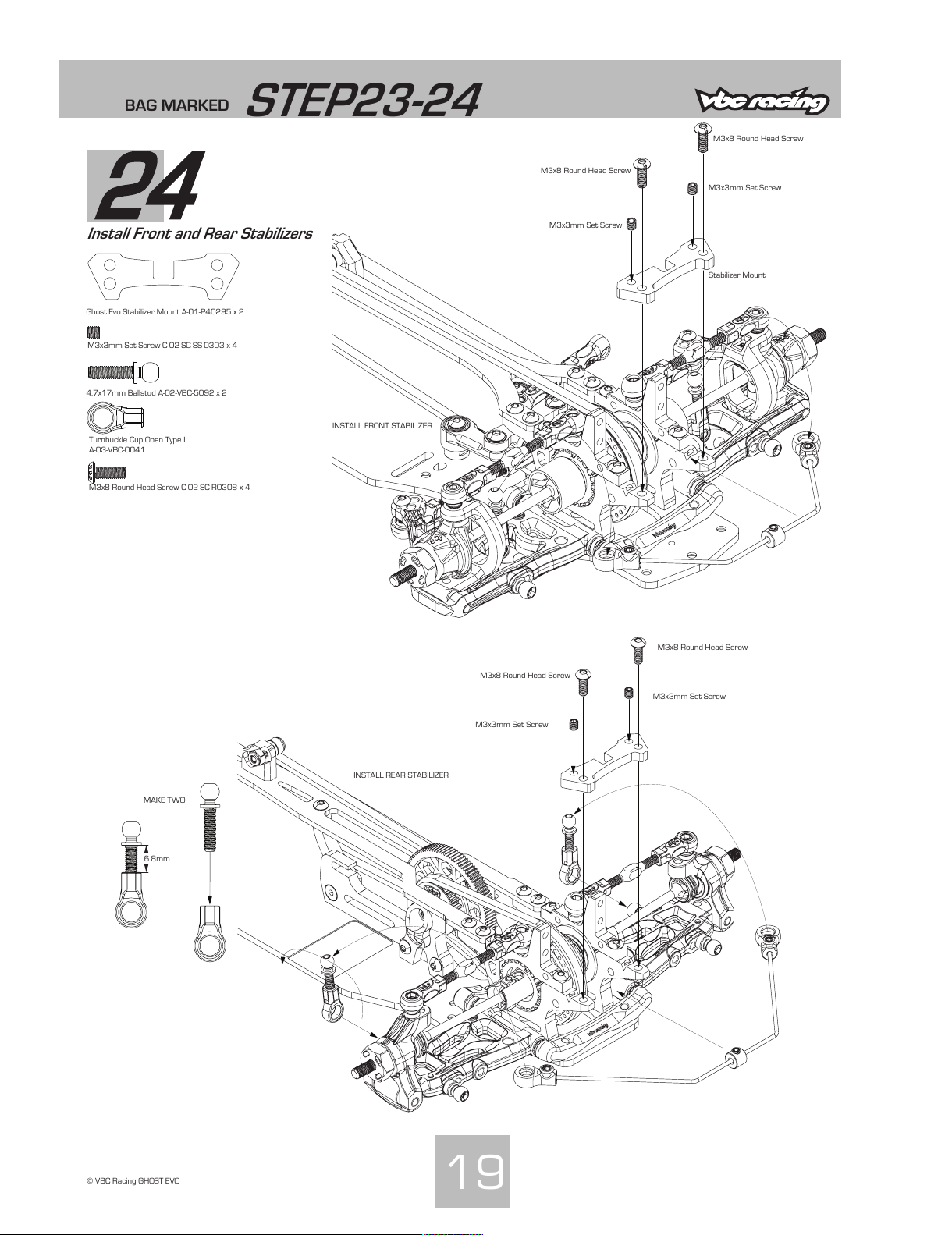
Install Front and Rear Stabilizers
19
© VBC Racing GHOST EVO
M3x3mm Set Screw C-02-SC-SS-0303 x 4
INSTALL FRONT STABILIZER
INSTALL REAR STABILIZER
M3x3mm Set Screw
Ghost Evo Stabilizer Mount A-01-P40295 x 2
M3x8 Round Head Screw C-02-SC-R0308 x 4
M3x8 Round Head Screw
M3x3mm Set Screw
M3x8 Round Head Screw
M3x3mm Set Screw
M3x8 Round Head Screw
M3x3mm Set Screw
M3x8 Round Head Screw
4.7x17mm Ballstud A-02-VBC-5092 x 2
Turnbuckle Cup Open Type L
A-03-VBC-0041
6.8mm
MAKE TWO
Stabilizer Mount
All manuals and user guides at all-guides.com
Page 21
BAG MARKED
STEP25-26
25
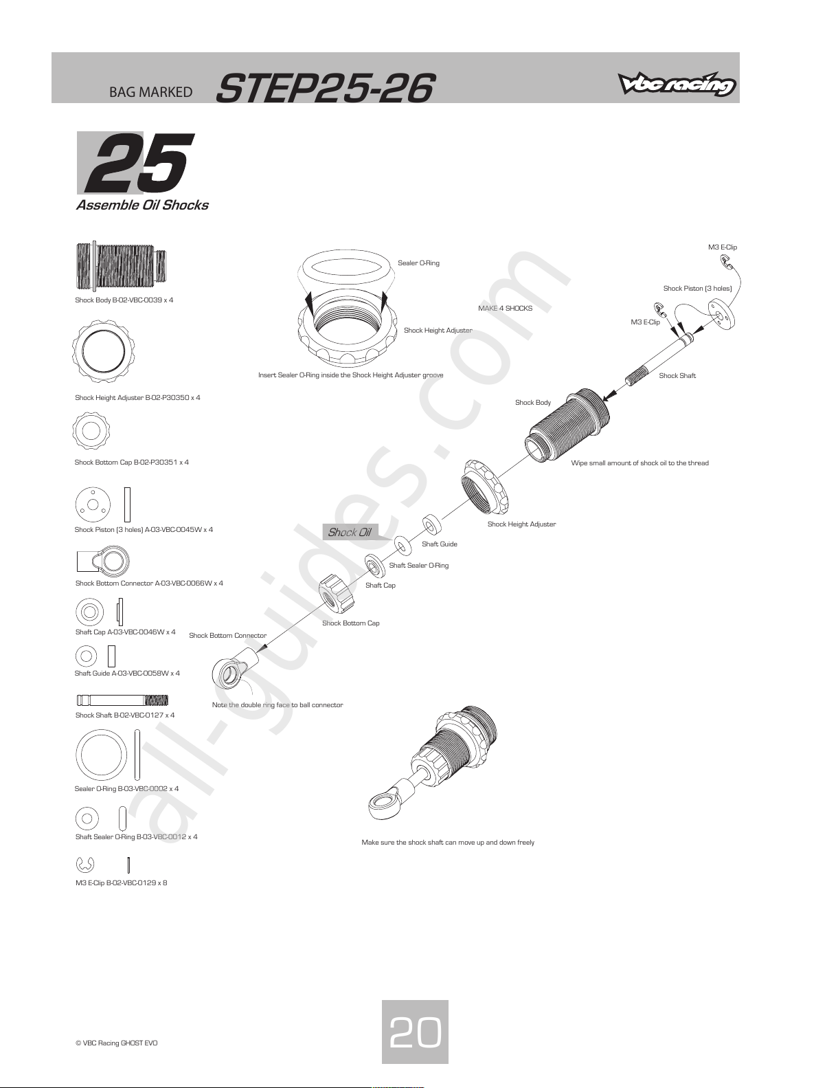
Assemble Oil Shocks
20
© VBC Racing GHOST EVO
Shock Body B-02-VBC-0039 x 4
Shock Height Adjuster B-02-P30350 x 4
Shock Bottom Cap B-02-P30351 x 4
Shock Piston (3 holes) A-03-VBC-0045W x 4
Shock Bottom Connector A-03-VBC-0066W x 4
Shaft Cap A-03-VBC-0046W x 4
Shaft Guide A-03-VBC-0058W x 4
Shock Shaft B-02-VBC-0127 x 4
Sealer O-Ring B-03-VBC-0002 x 4
Shaft Sealer O-Ring B-03-VBC-0012 x 4
M3 E-Clip B-02-VBC-0129 x 8
Insert Sealer O-Ring inside the Shock Height Adjuster groove
Make sure the shock shaft can move up and down freely
MAKE 4 SHOCKS
Wipe small amount of shock oil to the thread
Note the double ring face to ball connector
Shock Body
Shock Height Adjuster
Shock Bottom Cap
Shock Piston (3 holes)
Shock Bottom Connector
Shaft Cap
Shaft Sealer O-Ring
Shaft Guide
Shock Shaft
M3 E-Clip
M3 E-Clip
Sealer O-Ring
Shock Height Adjuster
Shock Oil
All manuals and user guides at all-guides.com
all-guides.com
Page 22
BAG MARKED
STEP25-26
26
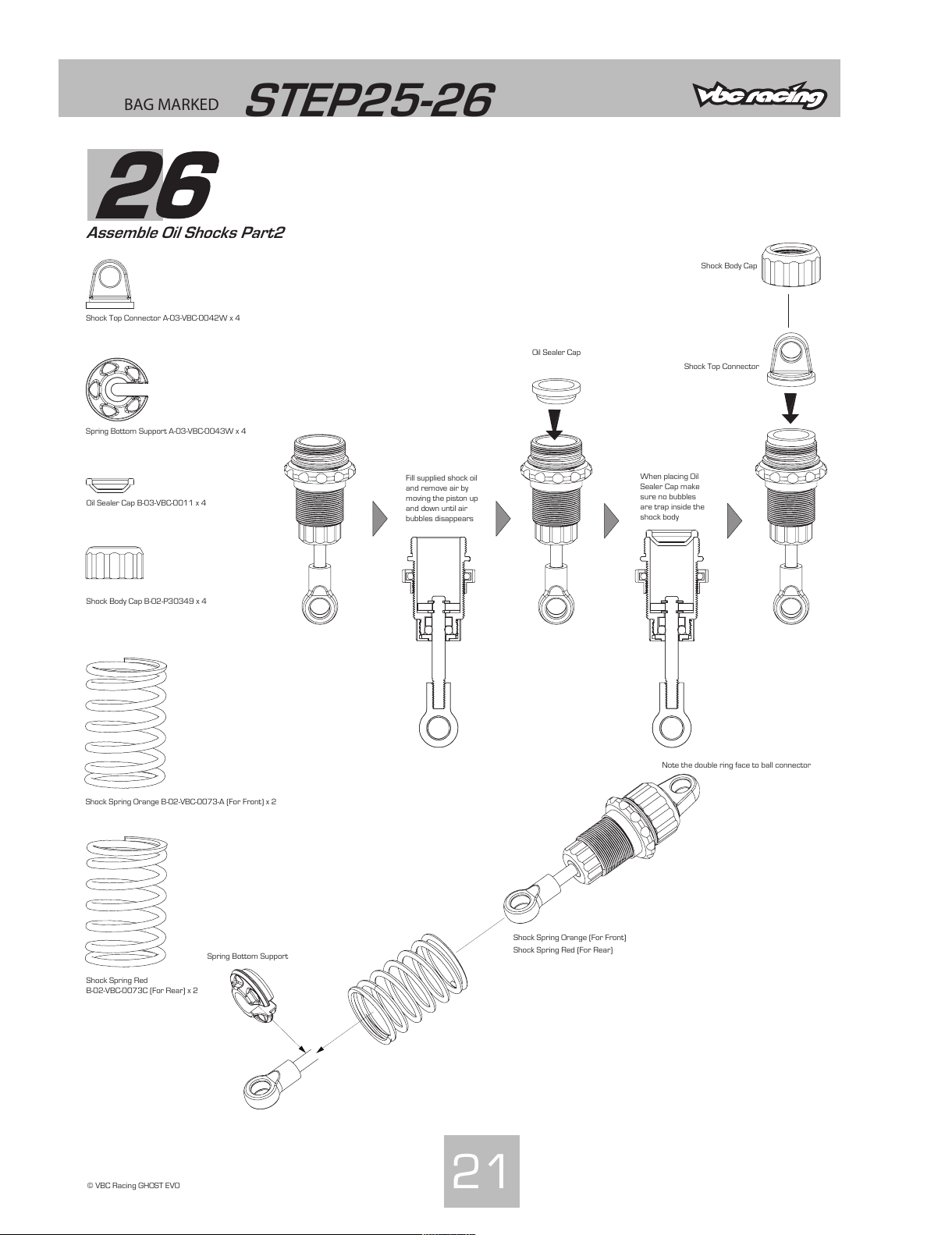
Assemble Oil Shocks Part2
21© VBC Racing GHOST EVO
Shock Top Connector A-03-VBC-0042W x 4
Spring Bottom Support A-03-VBC-0043W x 4
Oil Sealer Cap B-03-VBC-0011 x 4
Shock Body Cap B-02-P30349 x 4
Shock Spring Orange B-02-VBC-0073-A (For Front) x 2
Shock Spring Red
B-02-VBC-0073C (For Rear) x 2
Shock Body Cap
Shock Top Connector
Oil Sealer Cap
Fill supplied shock oil
and remove air by
moving the piston up
and down until air
bubbles disappears
When placing Oil
Sealer Cap make
sure no bubbles
are trap inside the
shock body
Shock Spring Red (For Rear)
Shock Spring Orange (For Front)
Spring Bottom Support
Note the double ring face to ball connector
All manuals and user guides at all-guides.com
Page 23
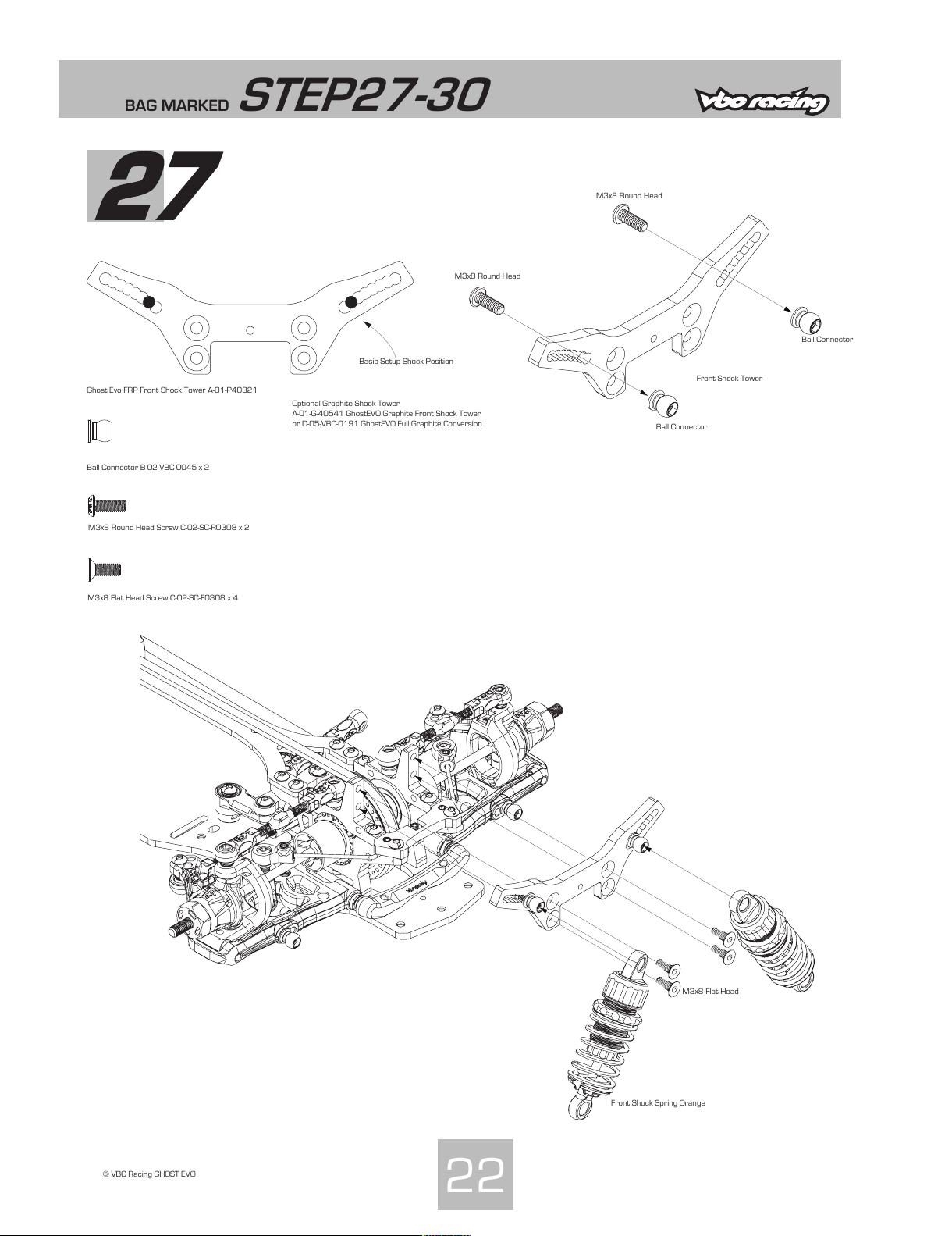
BAG MARKED
24
© VBC Racing GHOST EVO
Ghost Evo FRP Front Shock Tower A-01-P40321
Ball Connector B-02-VBC-0045 x 2
M3x8 Round Head Screw C-02-SC-R0308 x 2
Front Shock Tower
Ball Connector
M3x8 Round Head
M3x8 Flat Head Screw C-02-SC-F0308 x 4
Basic Setup Shock Position
M3x8 Round Head
Ball Connector
STEP27-30
27
22
Front Shock Spring Orange
M3x8 Flat Head
Optional Graphite Shock Tower
A-01-G-40541 GhostEVO Graphite Front Shock Tower
or D-05-VBC-0191 GhostEVO Full Graphite Conversion
All manuals and user guides at all-guides.com
Page 24
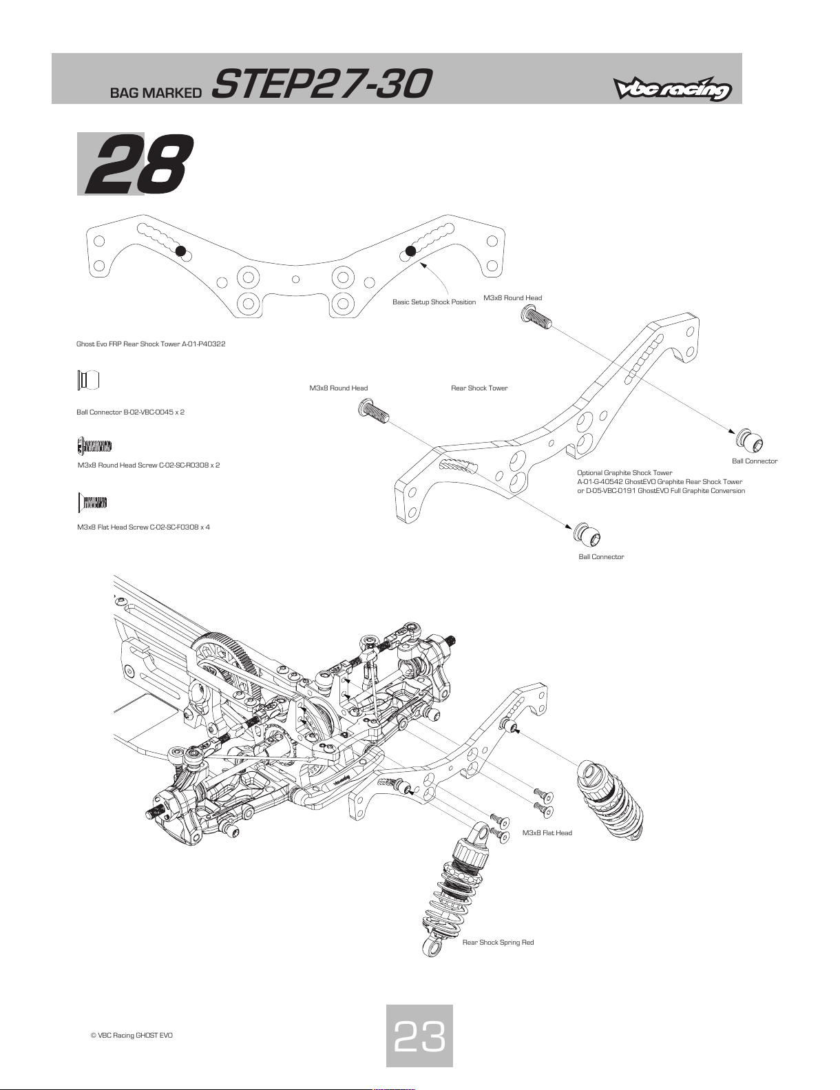
BAG MARKED
24
© VBC Racing GHOST EVO
Ghost Evo FRP Rear Shock Tower A-01-P40322
Ball Connector B-02-VBC-0045 x 2
M3x8 Round Head Screw C-02-SC-R0308 x 2
Rear Shock Tower
Ball Connector
M3x8 Round Head
M3x8 Flat Head Screw C-02-SC-F0308 x 4
Basic Setup Shock Position
M3x8 Round Head
Ball Connector
STEP27-30
28
23
Rear Shock Spring Red
M3x8 Flat Head
Optional Graphite Shock Tower
A-01-G-40542 GhostEVO Graphite Rear Shock Tower
or D-05-VBC-0191 GhostEVO Full Graphite Conversion
All manuals and user guides at all-guides.com
Page 25
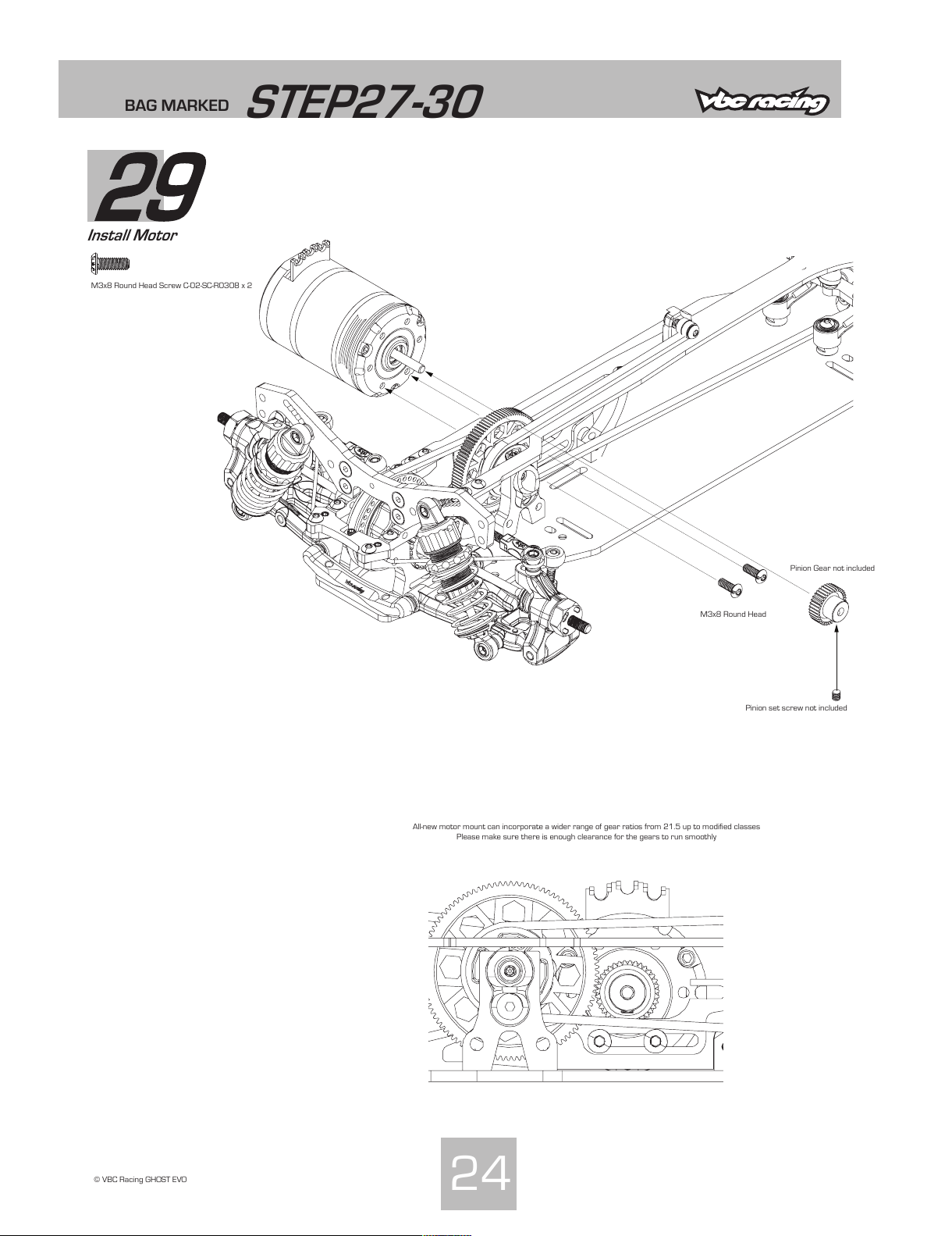
BAG MARKED
STEP27-30
29
Install Motor
24
© VBC Racing GHOST EVO
M3x8 Round Head
Pinion Gear not included
Pinion set screw not included
All-new motor mount can incorporate a wider range of gear ratios from 21.5 up to modified classes
Please make sure there is enough clearance for the gears to run smoothly
M3x8 Round Head Screw C-02-SC-R0308 x 2
All manuals and user guides at all-guides.com
Page 26
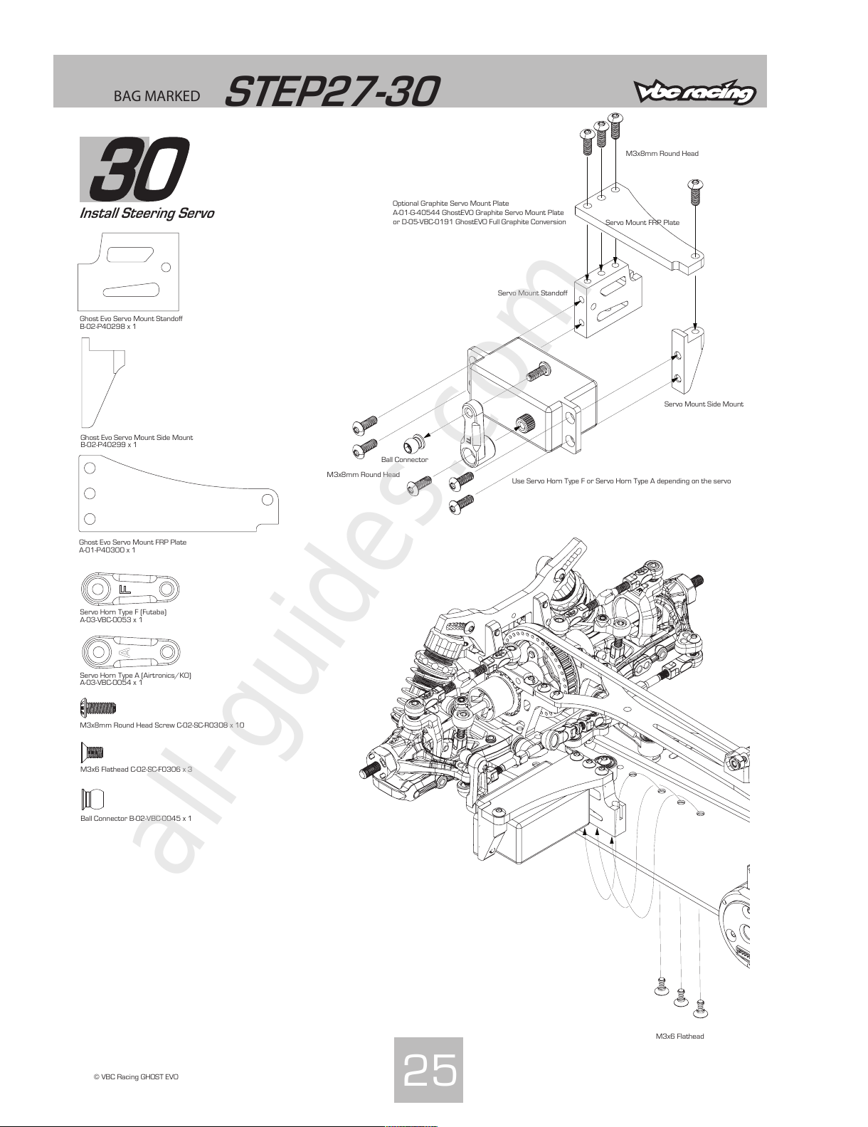
BAG MARKED
STEP27-30
30
Install Steering Servo
25
© VBC Racing GHOST EVO
Servo Horn Type F (Futaba)
A-03-VBC-0053 x 1
Servo Horn Type A (Airtronics/KO)
A-03-VBC-0054 x 1
Ball Connector B-02-VBC-0045 x 1
M3x8mm Round Head Screw C-02-SC-R0308 x 10
Ghost Evo Servo Mount Standoff
B-02-P40298 x 1
M3x8mm Round Head
M3x6 Flathead C-02-SC-F0306 x 3
Ball Connector
Use Servo Horn Type F or Servo Horn Type A depending on the servo
M3x8mm Round Head
Servo Mount Standoff
Ghost Evo Servo Mount Side Mount
B-02-P40299 x 1
Ghost Evo Servo Mount FRP Plate
A-01-P40300 x 1
Servo Mount Side Mount
Servo Mount FRP Plate
M3x6 Flathead
Optional Graphite Servo Mount Plate
A-01-G-40544 GhostEVO Graphite Servo Mount Plate
or D-05-VBC-0191 GhostEVO Full Graphite Conversion
All manuals and user guides at all-guides.com
all-guides.com
Page 27
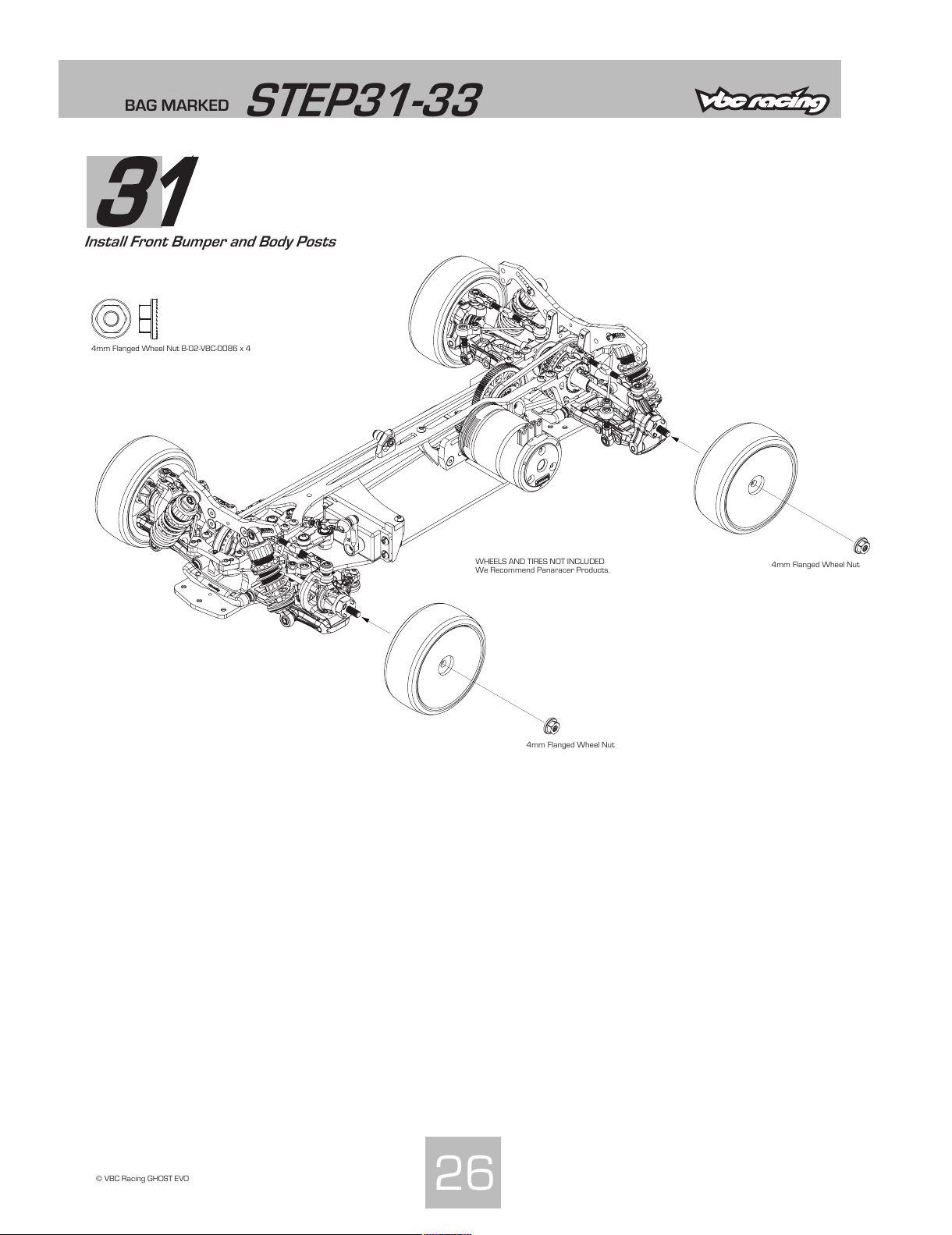
BAG MARKED
STEP31-33
31
Install Front Bumper and Body Posts
26
© VBC Racing GHOST EVO
4mm Flanged Wheel Nut B-02-VBC-0086 x 4
WHEELS AND TIRES NOT INCLUDED
We Recommend Panaracer Products.
4mm Flanged Wheel Nut
4mm Flanged Wheel Nut
All manuals and user guides at all-guides.com
Page 28
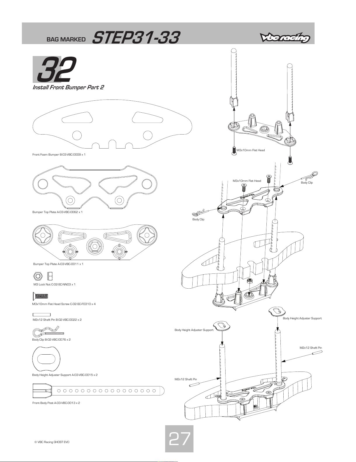
BAG MARKED
STEP31-33
32
Install Front Bumper Part 2
27
© VBC Racing GHOST EVO
M3x10mm Flat Head Screw C-02-SC-F0310 x 4
Front Foam Bumper B-03-VBC-0009 x 1
Bumper Top Plate A-03-VBC-0062 x 1
M2x12 Shaft Pin B-02-VBC-0022 x 2
Body Clip B-02-VBC-0076 x 2
Body Height Adjuster Support A-03-VBC-0015 x 2
M3x10mm Flat Head
Body Clip
Body Clip
Body Height Adjuster Support
Body Height Adjuster Support
M2x12 Shaft Pin
M2x12 Shaft Pin
M3x10mm Flat Head
Bumper Top Plate A-03-VBC-0011 x 1
M3 Lock Nut C-02-SC-NN03 x 1
Front Body Post A-03-VBC-0013 x 2
All manuals and user guides at all-guides.com
Page 29
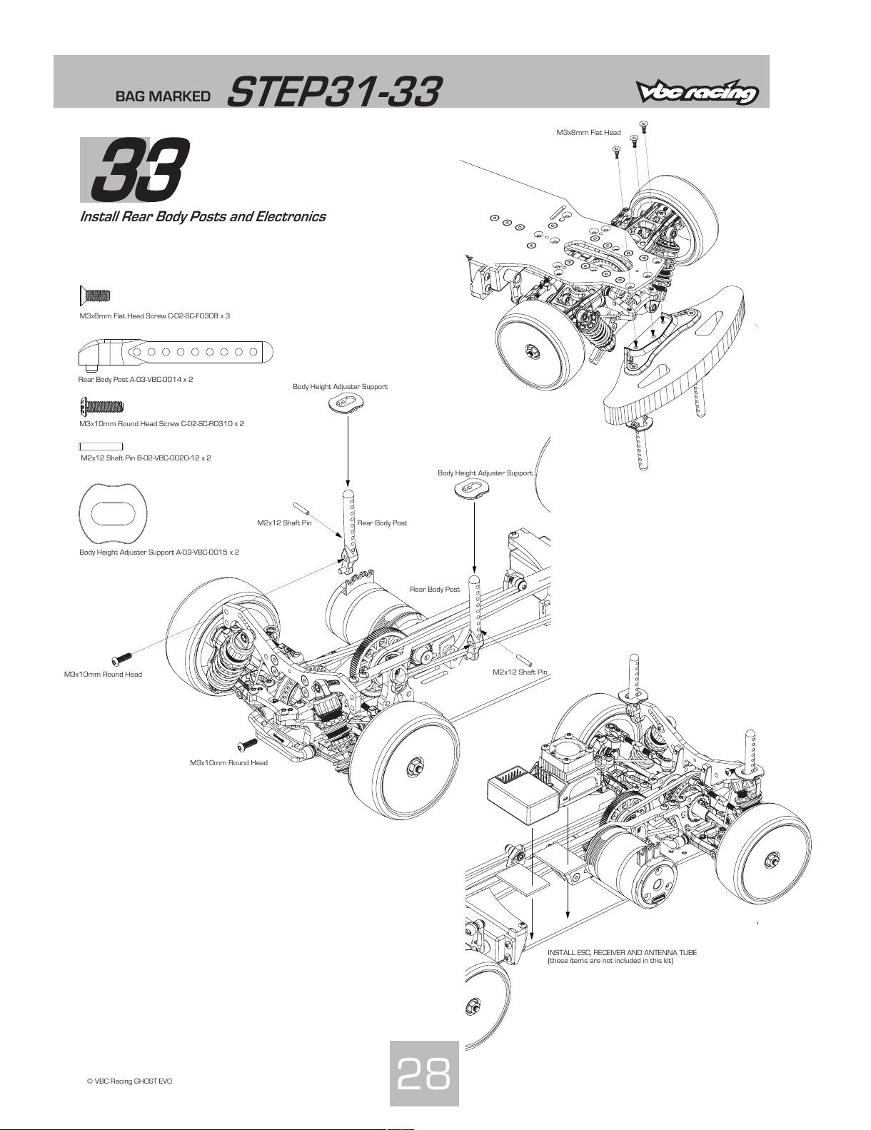
M3x8mm Flat Head Screw C-02-SC-F0308 x 3
M3x8mm Flat Head
BAG MARKED
STEP31-33
33
Install Rear Body Posts and Electronics
28
© VBC Racing GHOST EVO
Body Height Adjuster Support A-03-VBC-0015 x 2
M2x12 Shaft Pin B-02-VBC-0020-12 x 2
M3x10mm Round Head Screw C-02-SC-R0310 x 2
Rear Body Post A-03-VBC-0014 x 2
M3x10mm Round Head
INSTALL ESC, RECEIVER AND ANTENNA TUBE
(these items are not included in this kit)
M3x10mm Round Head
Body Height Adjuster Support
Body Height Adjuster Support
Rear Body Post
Rear Body Post
M2x12 Shaft Pin
M2x12 Shaft Pin
All manuals and user guides at all-guides.com
Page 30
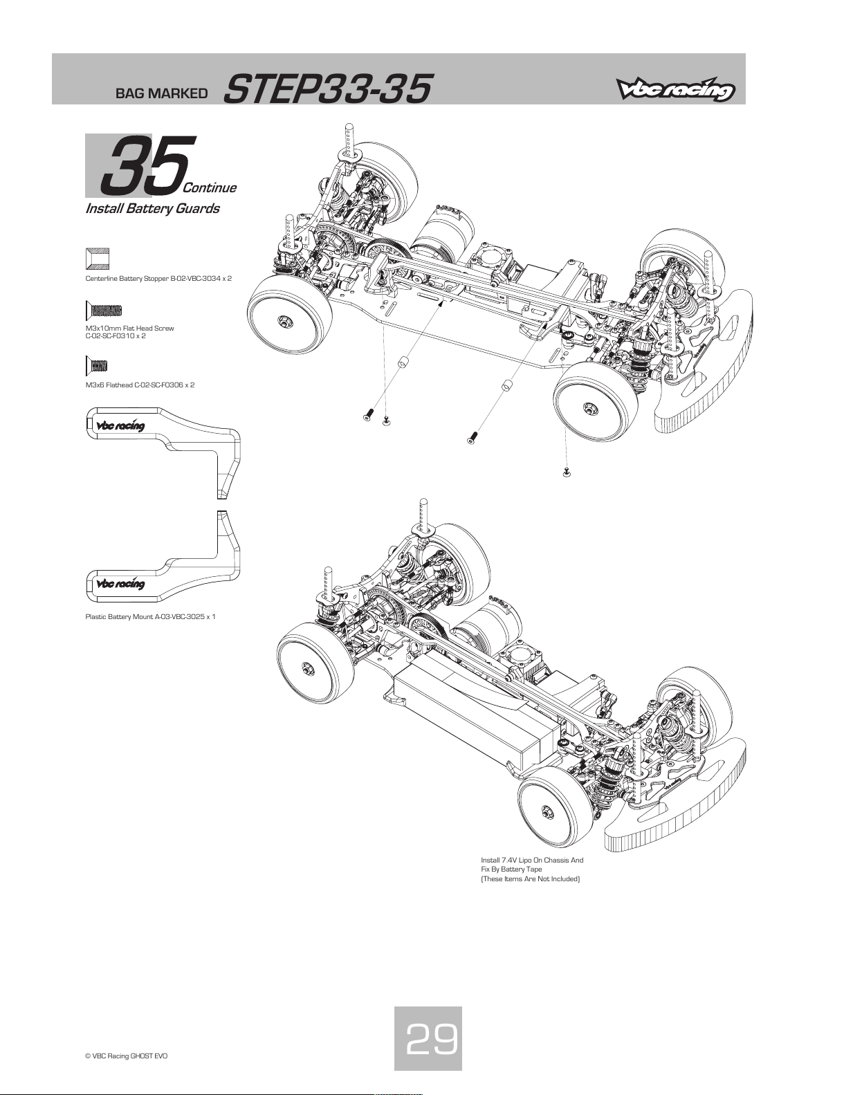
BAG MARKED
STEP33-35
35
Install Battery Guards
29
© VBC Racing GHOST EVO
Plastic Battery Mount A-03-VBC-3025 x 1
Continue
Centerline Battery Stopper B-02-VBC-3034 x 2
M3x10mm Flat Head Screw
C-02-SC-F0310 x 2
M3x6 Flathead C-02-SC-F0306 x 2
Install 7.4V Lipo On Chassis And
Fix By Battery Tape
(These Items Are Not Included)
All manuals and user guides at all-guides.com
Page 31

Instructions Book P-01-P40551.0 VBC Racing GhostEVO Car Kit D-05-VBC-CK09
All manuals and user guides at all-guides.com
all-guides.com
 Loading...