

Page 1

VAZ 2113
VAZ 2114
VAZ 2115
OPERATING MANUAL
RE2115eng 23/04/2002 15:23 Page 1
Page 2

CONTENTS
IIMPORTANT NOTICE !...........................................................................................4
VEHICLE DESCRIPTION .........................................................................................5
VEHICLE KEYS........................................................................................................5
DOORS.....................................................................................................................5
Front doors...........................................................................................................5
Rear doors............................................................................................................5
Tailgate.................................................................................................................7
BONNET...................................................................................................................7
BOOT LID .................................................................................................................8
FUEL TANK CAP......................................................................................................8
SEATS.......................................................................................................................9
STEERING RAKE ADJUSTMENT..........................................................................10
SEAT BELTS AND AIRBAG ....................................................................................10
MIRRORS AND INTERIOR.....................................................................................11
INSTRUMENTS AND CONTROLS.........................................................................12
INSTRUMENT CLUSTER.......................................................................................15
Instrument cluster test mode..............................................................................17
1. First type instrument cluster.......................................................................17
2. Second type instrument cluster.................................................................17
CONTROL SWITCHES...........................................................................................18
ON-BOARD CONTROL SYSTEM..........................................................................18
Modes of control module....................................................................................19
TRIP COMPUTER ..................................................................................................20
STEERING COLUMN STALK SWITCHES.............................................................21
DOOR MIRROR CONTROL...................................................................................21
GLOVE BOXES......................................................................................................22
FRONT ASHTRAY ..................................................................................................22
OPERATING NOTES..............................................................................................23
LICENSE PLATE....................................................................................................23
VEHICLE THEFT DETERRENT SYSTEM (IMMOBILIZER) ..................................23
Immobilizer System Disarming ...........................................................................24
Emergencies.......................................................................................................24
Courtesy Light ....................................................................................................25
USING IGNITION KEY AND KEY FOBS................................................................25
ENGINE START ......................................................................................................26
Cold start............................................................................................................26
DRIVING THE VEHICLE ........................................................................................27
BRAKING AND PARKING ......................................................................................28
TOWING .................................................................................................................29
«RUN-IN» PERIOD.................................................................................................29
2
RE2115eng 23/04/2002 15:23 Page 2
Page 3

NOTES ON USING VEHICLES WITH INJECTION ENGINES..............................29
INTERIOR VENTILATION AND HEATING CONTROL ..........................................30
SAFE DRIVING INSTRUCTIONS...........................................................................31
At the wheel........................................................................................................31
Before the trip .....................................................................................................31
Fording ...............................................................................................................31
Winter driving......................................................................................................32
Mountain driving.................................................................................................32
Using brakes.......................................................................................................32
Tyres and safe driving........................................................................................33
SERVICE AND MAINTENANCE............................................................................34
LUBRICATION SYSTEM........................................................................................34
ENGINE COOLING SYSTEM.................................................................................34
BRAKE SYSTEM....................................................................................................35
STORAGE BATTERY MAINTENANCE AND RECHARGING ................................35
WASHER FLUID .....................................................................................................36
SPARK PLUGS.......................................................................................................36
WHEELS AND TYRES...........................................................................................37
Wheel changing..................................................................................................38
FUSE REPLACEMENT ..........................................................................................38
BULB REPLACEMENT...........................................................................................41
BODYWORK MAINTENANCE ...............................................................................43
STORAGE...............................................................................................................44
TECHNICAL SPECIFICATION...............................................................................46
MAIN PERFORMANCE PARAMETERS AND DIMENSIONS ................................46
ENGINE PARAMETERS.........................................................................................48
VEHICLE SPECIFICATIONS..................................................................................48
CAPACITIES...........................................................................................................48
ADJUSTMENT AND CONTROL PARAMETERS ...................................................49
VEHICLE IDENTIFICATION DATA ........................................................................50
APPENDICES.........................................................................................................51
1. Fuels, lubricants and fluids.................................................................................51
2. Electric Bulbs Used in the Vehicle......................................................................52
3
RE2115eng 23/04/2002 15:23 Page 3
Page 4

4
IMPORTANT NOTICE !
You are now the owner of a comfortable passenger car that is distinguished for its
improved dynamics and speed characteristics. Regardless of your overall driving experience
we recommend you to be particularly careful during the initial period of vehicle operation
until you become familiar with your new Lada.
It is important, that you read this operating manual thoroughly before driving the vehicle.
The vehicle can be used on any type of roads except deeply rutted dirt roads.
The performance and reliability of your vehicle depend to a large extent on its correct use
and timely and thorough execution of servicing operations described in the Service Book.
In case your vehicle needs servicing or repair, we recommend that you take it to your
dealer’s station, which has necessary equipment and tools and can ensure professional standard of workmanship.
Use materials listed in Appendix #1 while operating or servicing the vehicle. Always
remember that a fuel injection engine with a catalytic converter requires only unleaded
fuel.
Never wash the vehicle with the engine running to avoid water coming into cylinders and thus
damaging the engine.
The design of the vehicle is subject to continuing improvement, therefore, some of the
component parts may differ from the descriptions, provided in the present manual.
RE2115eng 23/04/2002 15:23 Page 4
Page 5
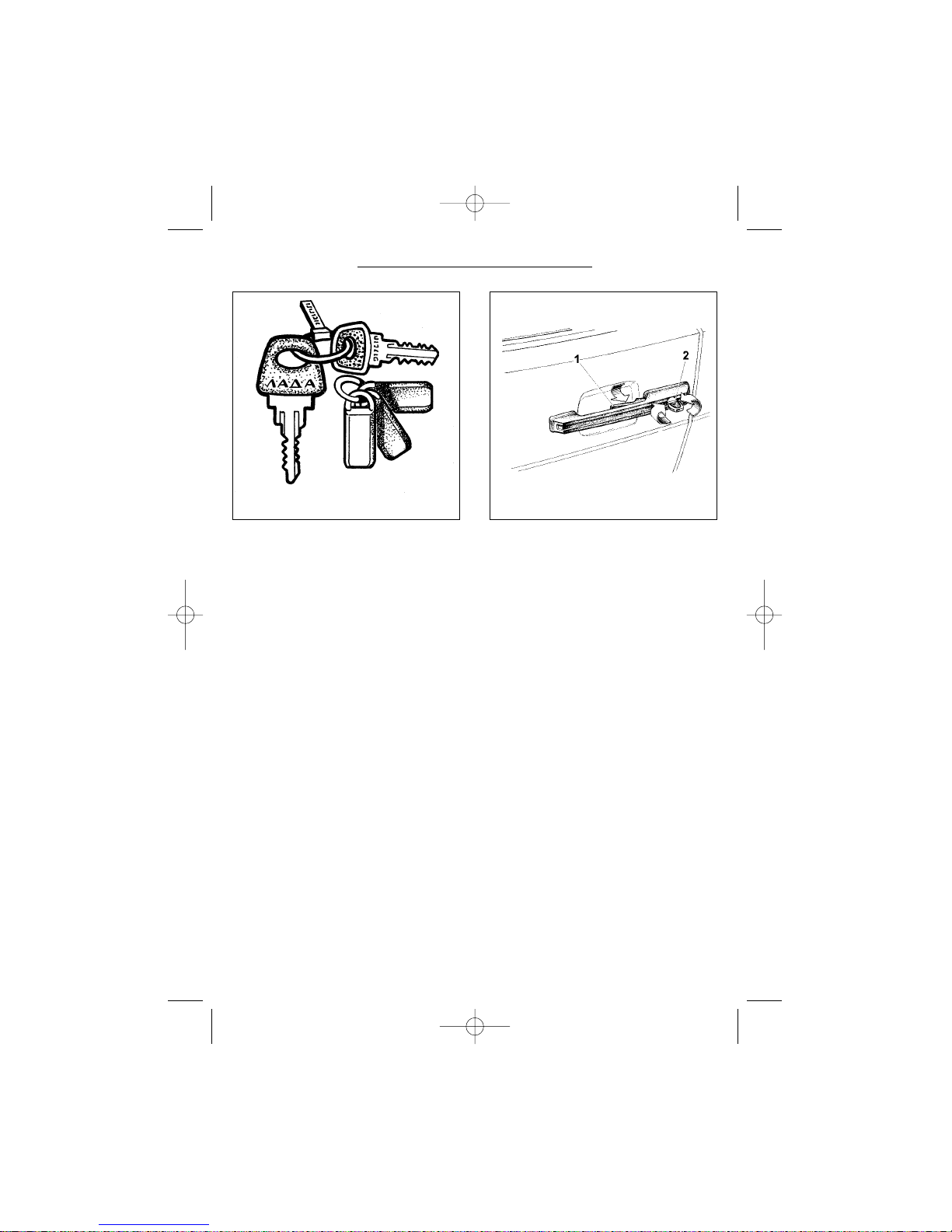
VEHICLE KEYS
Each car has two sets of keys. Each
set (Fig. 1) has two keys: one with plastic grip is the ignition key, one with
metal grip — door and boot key. The
number of the ignition key is shown on
the key ring tag. Cutting off the ring tag,
or replacing the ring will help you keep
the number of your key private.
A vehicle fitted with the anti-theft
system (immobilizer*) also has 3 key
fobs: 2 black key fobs for daily use, and
1 red key fob for immobilizer learning
purposes.
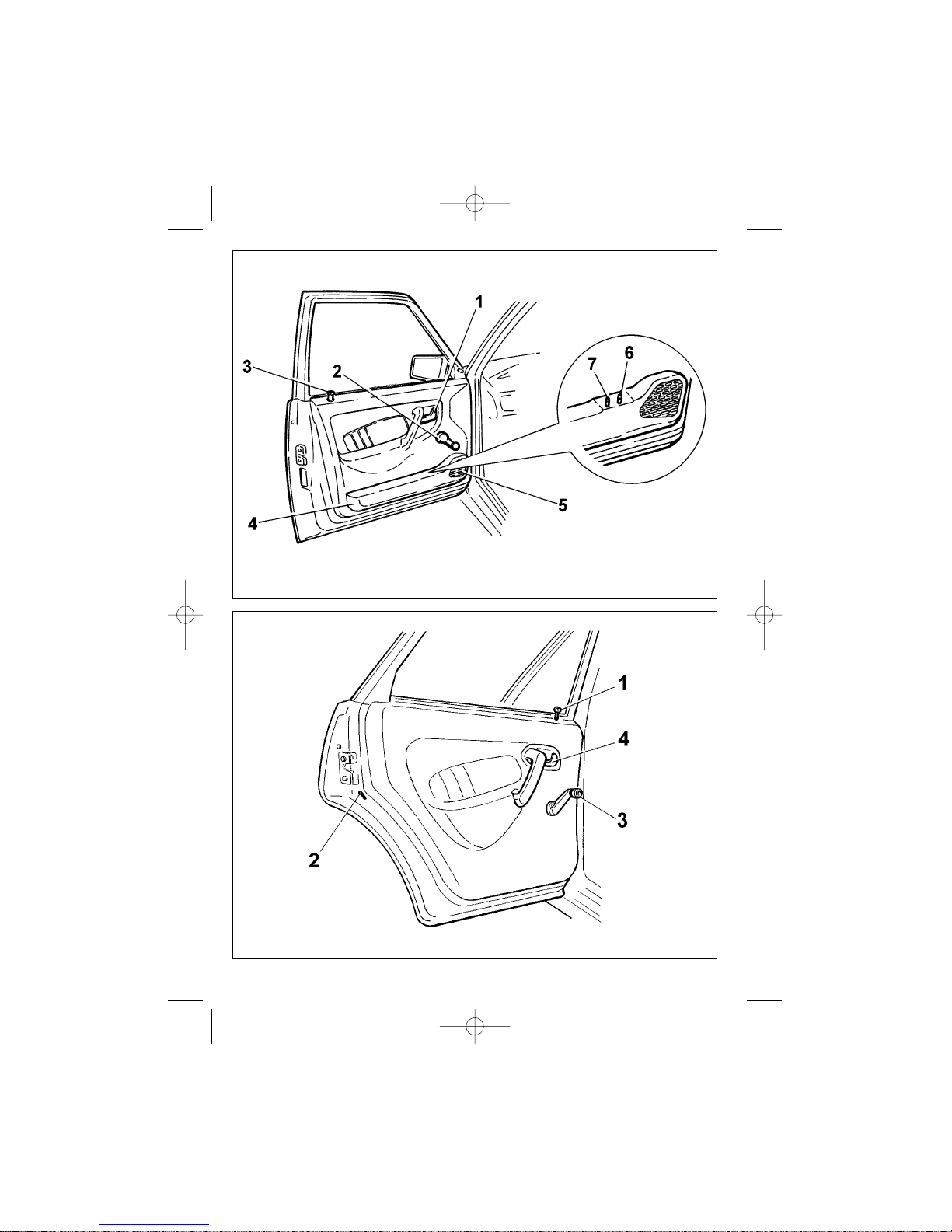
DOORS
Press button 1 (Fig. 2) or pull handle
1 (fig. 3) or 4 (Fig. 4) to open a vehicle
door. When the lock is engaged, handles will move freely without any effect
on the lock.
Front doors
Use key 2 (Fig. 2) or press button 3
(Fig. 3) to lock a door only when it is
closed.
Use handle 2 to wind the door window up or down. Some vehicles feature
power windows controlled by switches
7. Extra switch 6 on the driver’s door
armrest controls the front RH door window.
The front door features speaker bay
1 located under trimming 5 of the odds
compartment.
Rear doors
The rear doors (Fig. 4) have the
lock, which can be engaged by
depressing button 1, regardless
whether the door is open or closed.
Shift lever 2 to extreme lower position to partly engage the lock. In this
case, the door can be opened only
1* 5
VEHICLE DESCRIPTION
Fig. 1. Vehicle keys Fig. 2. Opening the door
______________
* If the immobilizer module fails to read the code stored in the key fob, it will not enable fuel injection pulses, thus providing further vehicle protection against unauthorized use.
RE2115eng 23/04/2002 15:23 Page 5
Page 6
6
Fig. 4. Rear door
Fig. 3. Front door
RE2115eng 23/04/2002 15:23 Page 6
Page 7
7
from outside, with button 1 fully up. We
recommend you to use the lock in this
manner when there are children on the
rear seat.
The rear door window can go only
part way down when you use window
winder 3.
Some vehicle options include central
door locking system, which may be
engaged by locking the driver’s door
with a key or by depressing its lock
knob. The doors can be unlocked individually by pulling up respective buttons.
It is not recommended to interlock
the doors while driving the car to
ensure the doors can be opened from
outside in the event of an accident.
Do not open the doors violently or
leave them open at a parking place
exposed to strong wind to avoid their
deformation.
During cold seasons when ice or
snow may cover the windows hampering their movement, do not apply
excessive force to wind the windows for
it may damage the mechanism.
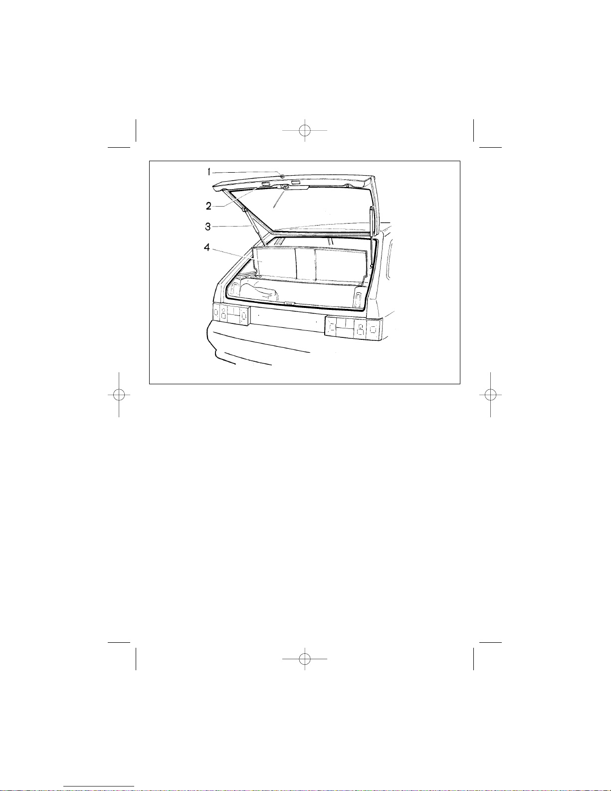
Tailgate
To open the tailgate, first unlock it
using a key, then depress button 1 (Fig.
5). The tailgate is held open by telescopic struts 3. Remove parcel shelf 4
to clear access to the luggage compartment.
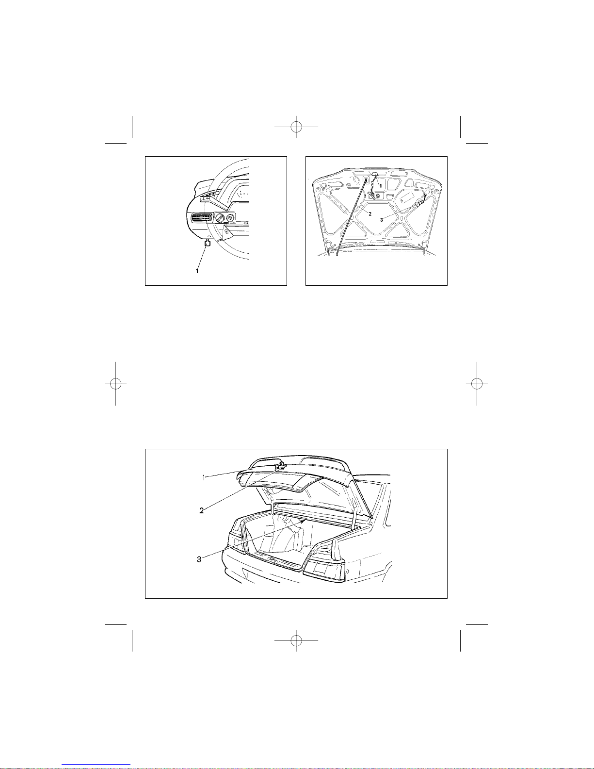
BONNET
To open the bonnet, pull handle 1
(Fig. 6), then lift the bonnet, and reaching through the gap, depress hook 1
Fig. 5. Tailgate
RE2115eng 23/04/2002 15:23 Page 7
Page 8
8
(Fig. 7). Now open the bonnet full way
and set up stay 2 as shown in the figure. If exterior illumination is on, lamp 3
will light up the engine bay. Rotate the
lamp holder to redirect the light.
When closing the bonnet, check a
reliable locking — a typical click should
be heard and the bonnet should remain
closed, when pressed upon. Before
closing the bonnet, make sure the safety hook moves freely without jamming
and always returns to its home position.
BOOT LID
To access the luggage compartment
turn key 2 (Fig. 8) clockwise and holding it in this position lift boot lid 1. The
boot lid is held open by torsion springs.
When the boot lid is up and the exterior lights are on, the luggage compartment is illuminated with lamp 3.
FUEL TANK CAP
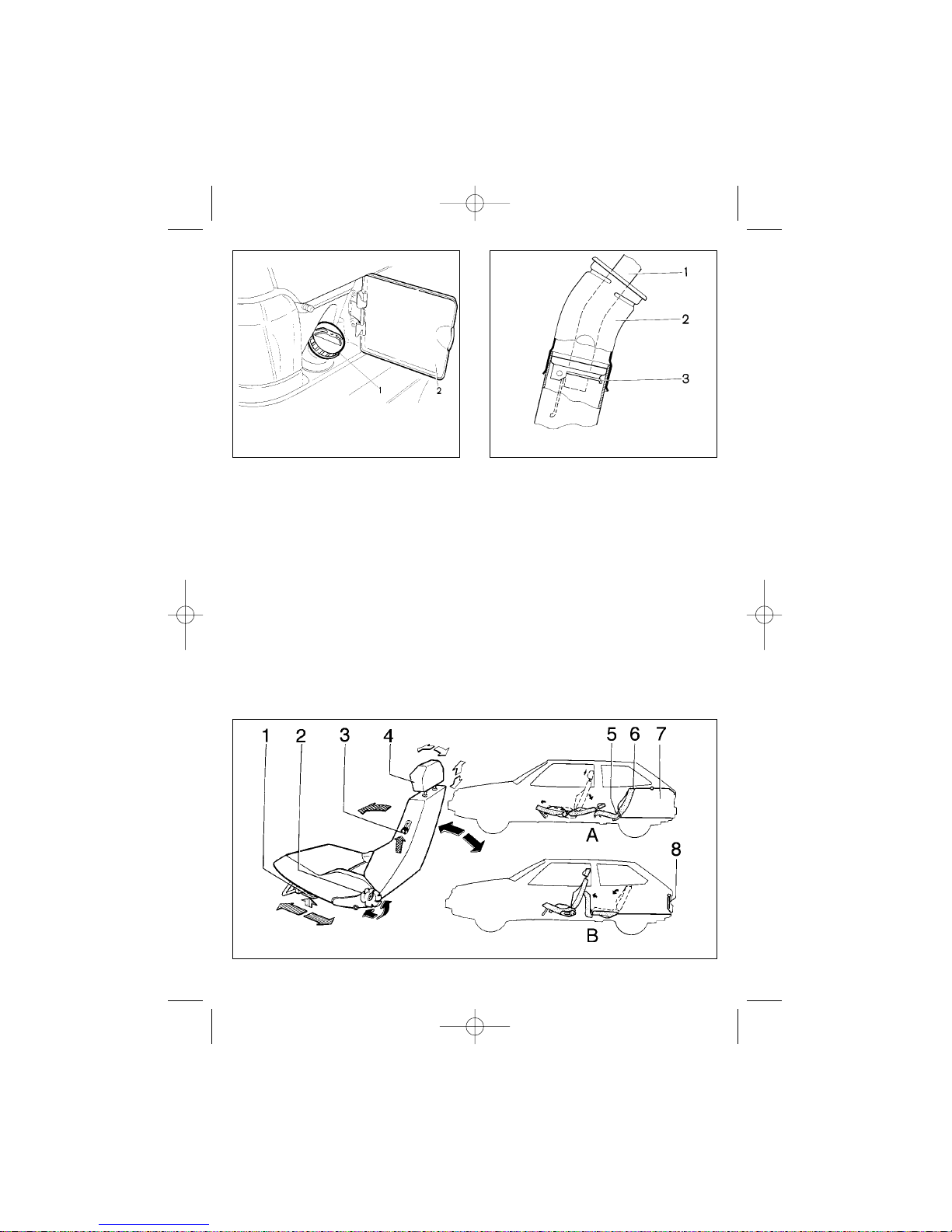
To access fuel tank cap 1 (Fig. 9),
open flap 2. All caps are equipped with
Fig. 6. Bonnet release handle
Fig. 7. Opening the bonnet
Fig. 8. Boot lid
RE2115eng 23/04/2002 15:23 Page 8
Page 9
9
a torque limiter, intended to ensure a
reliable cap-to-filler neck sealing.
The cap should be tightened until
the torque limiter starts to click.
Some vehicles feature fuel tank
caps connected to vehicle body by
means of a flexible cable. This ensures
that the cap does not get lost while filling in, it also does not allow you to
close flap 2 when the filler neck is not
closed with the cap.
Vehicles with a catalytic converter
feature filler neck 2 (Fig. 10) with built-
in valve 3, which makes it possible to
use a smaller size fuelling nozzle to fill
in unleaded gasoline.
SEATS
For longitudinal travel adjustment of
the front seats, pull up locking lever 1
(Fig. 11, 12). With the seat in the
desired position, release the lever, and
moving the seat slightly back and forth,
make sure, it has been reliably fixed.
Backrest tilt can be adjusted by rotating
Fig. 10. Fuel tank filler neckFig. 9. Fuel tank cap
Fig. 11. Seats
RE2115eng 23/04/2002 15:23 Page 9
Page 10
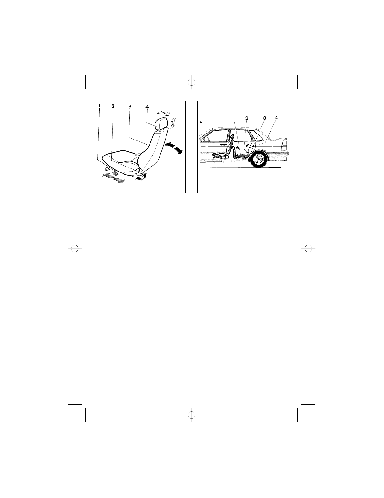
knob 2 (Fig. 11, 12). View «A» shows
the front seat arrangement for comfortable rest.
To let the rear passenger in and out
(VAZ 2113 and modifications), move up
lever 3 and tilt the front seat backrest
forward.
To increase the luggage space (7),
do the following (for VAZ 2113, VAZ
2114 and modifications):
— remove parcel shelf 8 and place it
along the rear wall of the boot (see
view «B» in Fig. 11);
— pull loop 5 and put the cushion
vertically.
— move lever 6 to the right, release
the backrest and fold it down. When
necessary, move the front seat forward;
Headrests 4 (Fig. 11, 12) are height
and tilt adjusted. They are held in position by retainer springs.
The rear seat of VAZ 2115 can be
transformed to increase the luggage
compartment space for various cargoes transportation. Fold the rear seat
as follows:
— pull loop 2 (Fig. 13) to place cushion 1 vertically;
— remove headrests, then shift
lever 3 to the right, release backrest 4
and place it as shown in the illustration.
When necessary, move the front seats
forward.
STEERING RAKE
ADJUSTMENT
Following adjustment of the seat
position, tilt the steering column to a
position most suitable for comfortable
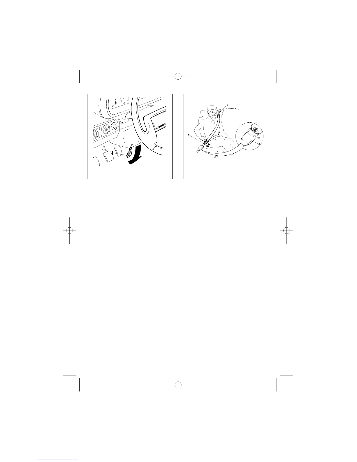
driving. Move lever 1 (Fig. 14) down,
then select a desired tilt angle of the
steering column and shift the lever up
to lock the column in this position.
SEAT BELTS AND AIRBAG
In order to fasten a seatbelt, slip
tongue 1 (Fig.15) into buckle 2 to hear
a click. Check to see, that the straps
are not twisted.
To unfasten the belt, push button 3
of the buckle.
The passengers, sitting in the rear,
fasten their belts similarly. The occu-
10
Fig. 13. VAZ-2115 rear seat
transformationFig. 12. Front seat
RE2115eng 23/04/2002 15:23 Page 10
Page 11
pant, sitting in the middle of the rear
seat, has a lap belt only.
Do not use the belt to restrain a child
sitting on the passenger’s lap.
If the belts are dirty, clean them with
soft soapy water. Never iron the seat
belts. The seat belt is subject to
mandatory replacement if it was subjected to critical loads in a road accident or is chafed, torn or otherwise
damaged.
Some models are available with an
airbag in the steering wheel being recognized by an inscription «AIRBAG»
on the steering wheel cover plate. The
airbag is designed as an additional protection, along with the seat belt, to the
driver’s safety during an accident. The
airbag is triggered at the head-on collision.
The airbag is a reliable maintenance-free, self-contained unit of disposable type. In order to ensure maximum protection and reduce possible
injuries during an accident, do not stick
any labels or fit any accessories to the
steering wheel. During inflation of the
airbag a small amount of powdery sub-
stance is emitted. This powder,
although harmless to health, may
cause skin or eye irritation. In case of
exposure to such powder wash the
eyes with water and clean the skin with
neutral soap. After the airbag triggering, do not touch the centre of the
wheel or cut off the airbag to avoid cuts
and burns. Replacement of the airbag
should be entrusted to your dealer. The
seat belts, exposed to critical loads,
must be replaced along with the airbag.
MIRRORS AND INTERIOR
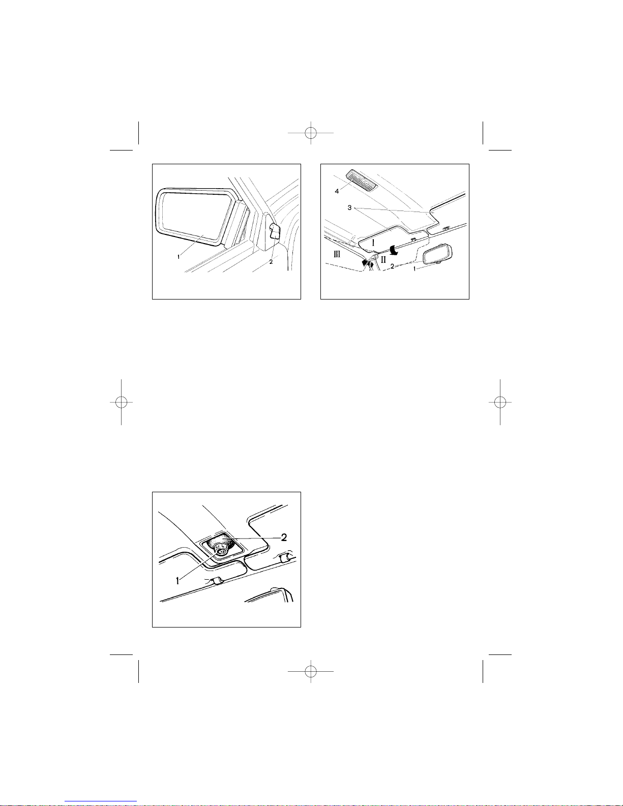
Use knob 2 to adjust exterior
rearview mirror 1 position (Fig. 16).
Some vehicles are equipped with electrically-operated door mirrors.
Interior rearview mirror 2 (Fig. 17) is
adjusted by rotation on the pivot ball. To
avoid dazzling by the lights of upcoming traffic change the mirror angle using
lever 1.
Some vehicles are equipped with an
antidazzle mirror, which does not have
a lever and cannot be adjusted.
11
Fig. 15. Seat beltsFig. 14. Steering rake adjustment lever
RE2115eng 23/04/2002 15:23 Page 11
Page 12
12
You may select among three positions (I, II or III) of sun visors 3 depending on the sun light.
The passenger’s sun visor may
optionally feature a vanity mirror.
The interior light (4) goes on automatically as the vehicle door opens
(courtesy light) and goes off 10 seconds after the door closing or after the
ignition key is switched to the «Ignition»
position.
When the doors are closed the interior light can be switched on/off by
pushing its lens at the side.
The reading lamp is intended for
spotlighting individual objects. To
switch on the reading light, twist lamp
casing ring 1 (Fig. 18) clockwise. The
lamp (2) beam axis can turn over 30° in
all directions. To switch off the reading
light twist lamp casing ring counterclockwise.
INSTRUMENTS AND
CONTROLS
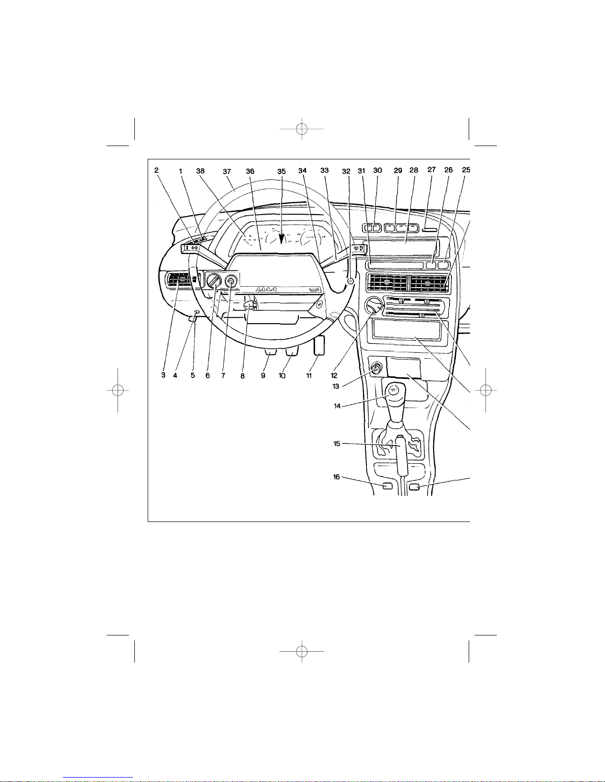
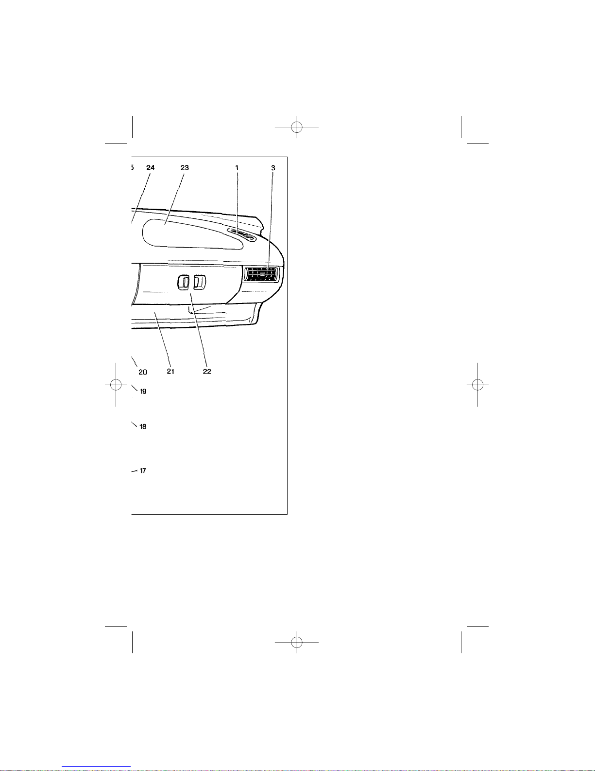
The location of instruments and controls is shown in Fig. 19.
1 — Side demister register.
2 — Turn indicators and main/ low
beam stalk switch.
3 — Interior ventilation and heating system side registers.
4 — Inspection lamp socket.
5 — Bonnet release handle.
6 — Headlight hydraulic adjuster
with manual adjustment.
Rotating the knob, adjust the headlight beam angle to match the vehicle’s
load and avoid dazzling the drivers of
the on-coming traffic. Read the adjuster
knob positions as follows:
1 — driver only;
Fig. 17. Interior (detail)
Fig. 18. Reading lamp
Fig. 16. Exterior rearview mirror
adjustment
RE2115eng 23/04/2002 15:23 Page 12
Page 13

13
2 — driver and four passengers;
3 — driver, four passengers and
cargo in the luggage compartment up
to the maximum load on the rear axle;
4 — driver and cargo in the luggage
compartment up to the maximum load
on the rear axle.
7 — Instrument cluster illumination control.
When the headlights are on, rotate
the knob to adjust the brightness of
instrument cluster illumination.
8 — Steering wheel tilt control
lever (See Fig. 14).
9 — Clutch pedal.
10 — Brake pedal.
11 — Accelerator pedal.
12 — Heater electric fan switch.
13 — Cigarette lighter.
To use the lighter, push it in all the
way, then release. In about 20 seconds, the lighter pops back, ready for
use.
14 — Gear change lever.
The gear change pattern is shown
on the handle.
15 — Handbrake lever.
Pulling the lever up activates the
rear wheel brake shoes. To return the
lever to its original position, press the
button at the top of the lever.
16 — Front left seat heating control. (See Control Switches).
Optional.
17 — Front right seat heating control. (See Control Switches).
Optional.
18 — Front ashtray. (See Fig. 26).
19 — Radio/cassette player bay.
The bay may accommodate a
radio/cassette player having international standard dimensions and fixing.
20 — Interior ventilation and heat-
ing system control.
21 — Trinket tray.
22 — Lower glove box cover.
23 — Upper glove box cover.
24 — Interior ventilation and heat-
ing system central registers.
25 — Air bag warning light.
If the vehicle features an air bag system, the indicator is fitted instead of the
plug. It lights up for 4-5 seconds after
ignition switch-on, indicating that the
system self test is in progress. The light
goes off if no fault was found, otherwise
it illuminates continuously indicating a
failure in the system. The warning light
may be fitted in the steering wheel
spoke as an option.
Some vehicles feature a headlight
wiper/washer switch in place of the air
bag warning light. (See Control
Switches).
26 — ABS warning light.
If the vehicle features an anti-lock
braking system, the indicator is fitted
instead of the plug. It lights up in
orange colour when ignition is on and
goes off in 2-3 seconds if the system is
OK. If the light illuminates continuously
contact your servicing agent.
27 — Plug.
28 — Plug.
Some vehicles feature a trip computer in its place.
29 — Control switches. (See
Control Switches).
30 — Exterior lights switch. (See
Control Switches).
31 — On-board control system.
32 — Immobilizer key reader.
It is fitted on the vehicles with the
Vehicle Theft Deterrent System
RE2115eng 23/04/2002 15:23 Page 13
Page 14
(Immobilizer) and is designed to read
the code from the key fobs.
33 — Windscreen wiper/washer
stalk switch.
34 — Ignition switch.
35 — Hazard light switch.
Push this button to flash all the turnsignal lamps and the hazard light telltale. To turn OFF, push the button
again.
36 — Horn push pad.
37 — Steering wheel.
38 — Instrument cluster.
14
Fig. 19. Instruments and controls
RE2115eng 23/04/2002 15:23 Page 14
Page 15
INSTRUMENT CLUSTER
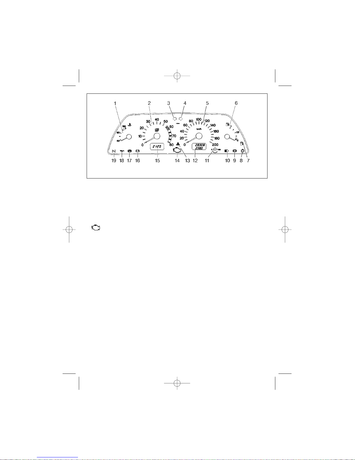
1 (Fig. 20) — Engine coolant tem-
perature gauge.
The pointer in the red zone indicates
engine overheating. Check the radiator
fan and the thermostat operation.
2 — Tachometer.
Indicates engine speed. The red
hatching zone indicates higher engine
RPM, the red zone — hazardous
engine speed.
3 — LH turn-signal indicators telltale.
Illuminates in intermittent green
when the LH turn-signal indicators are
ON.
4 — RH turn-signal indicators telltale.
Illuminates in intermittent green
when the RH turn-signal indicators are
ON.
5 — Speedometer.
6 — Fuel gauge.
7 — Fuel reserve tell-tale.
Lights up in orange when less than
7-9.5 litres of fuel remain in the tank, of
which 3 litres are unusable fuel
reserve. Never run a vehicle until the
fuel tank is empty! This may damage
the fuel pump.
8 — Side-marker tell-tale.
Goes ON in green colour when exterior lights are ON.
9 — Brake system emergency telltale.
Goes ON in red colour when the
brake fluid level is below the «MIN»
mark on the tank.
10 — Main beam tell-tale.
Goes ON in blue colour when main
beam is ON.
11 — Trip counter reset knob.
12 — Trip counter.
The top line of the display indicates
vehicle total mileage, the bottom line
indicates daily trip. With the vehicle
stopped, press button 11 and hold it
down for at least 3 seconds to reset the
15
RE2115eng 23/04/2002 15:23 Page 15
Page 16
16
counter. Disconnecting the storage battery also resets the daily trip counter.
13 — Hazard light tell-tale.
Flashes red when the hazard light is
ON.
14 — Malfunction Indicator Lamp
« » (CHECK ENGINE).
For fuel injection engines only.
Lights up briefly after ignition switch-on
indicating system self-test and goes off
if no fault is found. The MIL may flash
or illuminate continuously if a fault is
detected.
15 — Time/Temperature LCD.
Depress knob 11 briefly to switch
between time and temperature readings.
With the ambient temperature +2°C
or higher the display will indicate time.
With the ambient temperature below
+2°C the display will indicate time for
the first three seconds, then temperature readings will be displayed (intermittently for the first 10 seconds).
If the ambient temperature rises
above +3°C and then drops again to
+2°C:
— time reading will switch to temperature reading (intermittent for the
first 10 seconds)
— continuous temperature indication will become intermittent for 10 seconds.
Set the clock in the time indication
mode by rotating knob11 towards «h»
(hour) or «m» (minute).
After battery disconnection/reconnection the time reading will be reset to
zero.
16 — Low battery tell-tale.
Lights up in red colour at ignition
switch-on and goes off immediately
upon the engine start-up. Intense or
moderate illumination of the lamp with
the engine running indicates a slack or
failed alternator drivebelt, a fault of the
alternator or its circuit.
17 — «Parking brake applied» telltale.
Goes on in red when the parking
brake is applied.
18 — Low oil pressure tell-tale.
Lights up in red when the lubrication
system pressure is low.
19 — Spare.
Fig. 20. Instrument cluster
RE2115eng 23/04/2002 15:23 Page 16
Page 17

17
For vehicles with fuel injection only.
For carburetor engines this light is used
as the carburetor choke tell-tale light.
Instrument cluster test mode
There are two types of LCD instrument cluster that may be installed on a
vehicle.
Press the (daily) Trip counter reset
knob and simultaneously switch ignition on (apply voltage to terminal 15 of
ignition switch and further to the instrument cluster; the engine not running) to
activate the instrument cluster test
mode indicated as follows:
1. First type instrument cluster.
• The gauge pointers sway three
times full way; all characters on the
LCD and the fuel reserve tell-tale illuminate.
• Press and then release the reset
knob to show the number of the instrument cluster firmware version (e.g. UEr
1.1, UEr 0.8, or other) on the daily/total
trip counter display. The indication
stays for about 20 seconds, after which
the instrument cluster automatically
resumes its normal mode of operation.
• Press/release the knob again to
display the last saved DTC.
• Reset the indication by depressing
the reset knob and holding it down for
over 5 seconds.
Read the display 15 seconds after
resetting as follows:
— «0» indicates that the system is
fault-free;
— «1» indicates a fault of the micro-
processor;
— «2» indicates an opening in the
fuel level sensor circuit;
— «4» indicates high on-board sys-
tem voltage (over 16 V);
— «8» indicates low on-board sys-
tem voltage (below 8 V);
— in case of multiple failures the
system displays a resulting code, which
is a sum of all the present fault codes,
e.g. «6» (2+4), «10» (2+8), «12» (4+8),
«14» (2+4+8).
• If the tachometer reads a signal
(the engine is running), the test mode is
canceled and the instrument cluster
switches to its normal operational
mode.
• In case of over- (16 V and higher)
or undervoltage (below 8 V) the gauge
pointers freeze until the fault is
repaired.
2. Second type instrument cluster.
• Ahalf-way sway of gauge pointers,
then a full sway, the clock/temperature
LCD reads «test», the daily/total trip
LCD displays 10123456789 in a creeping line, and the fuel reserve tell-tale
illuminates.
• In case any of the instruments
reads an input signal (e.g. the engine is
running), the instrument cluster will
complete the test as per 2.1 and
resume its normal operation.
• In case of no input signals to the
cluster, the gauge pointers sway
halfway several times, then sway full
way, the clock/temperature LCD reads
«test», the daily/total trip LCD displays
10123456789 in a creeping line, and
the fuel reserve tell-tale illuminates.
• In case of over- (16 V and higher)
or undervoltage (below 8 V) the gauge
pointers freeze until the fault is
repaired.
RE2115eng 23/04/2002 15:23 Page 17
Page 18
CONTROL SWITCHES
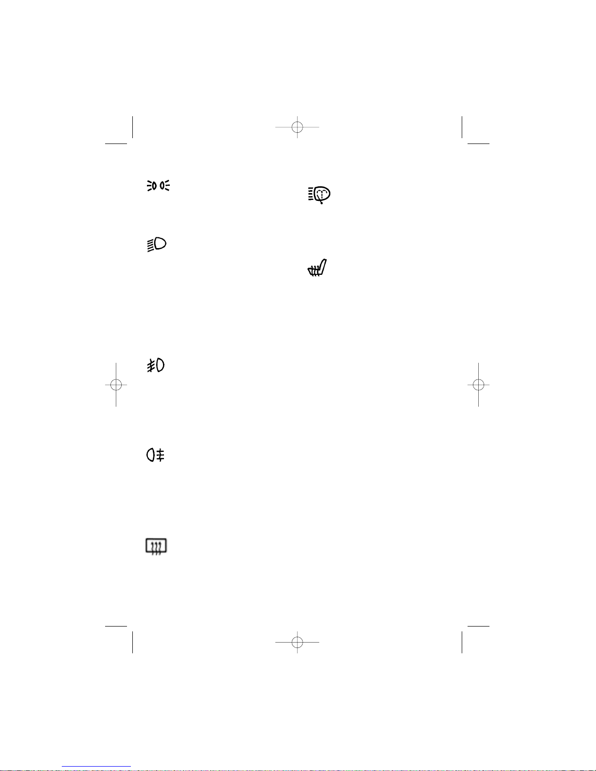
— Side-marker switch.
Depress this control button
to switch the side-markers
on/off. The control button illuminates when the side-markers
are on.
— Headlight switch.
Depress this control button
to energize the headlight circuit.
The side-marker and the
headlight switches are grouped
into the «Exterior light control».
Mechanical design of the switch
disallows activation of headlights without switching the
side-markers first, as well as
deactivation of the side-markers
when the headlights are on.
— Fog lamp switch.
Depress this control switch
to activate the fog lamps when
visibility is limited (snow, fog,
etc.). The side-markers must be
on. The button will illuminate to
indicate that the fog lamps are
on. Depress the button again to
switch the fog lamps off.
— Rear fog light switch.
Depress this control switch
to activate the rear fog light and
illuminate the button when the
exterior lights are on. Depress
the button again to switch the
fog light off. The rear fog light
goes off automatically with ignition switch-off.
— Rear window defroster
switch.
Depress this control switch
to activate the rear window
defroster. The button will illuminate to indicate that the
defroster is on. Depress the
button again to switch the rear
window defroster off.
— Headlamp wiper/washer
switch.
Optional. With the head
lamps on depress and hold
down this control switch to activate the headlamp wiper/washer.
— Front seat heating
switch.
Optional. Depress this control switch to activate the front
seat heating. A built-in thermal
regulator automatically maintains the heating element temperature for the seat backrest
and cushion within 25-31°C.
Depress the control again or
switch ignition off to deactivate
the front seat heating.
ON-BOARD CONTROL
SYSTEM
The on-board control system is
optional (Fig. 21).
1 — low oil tell-tale.
Lights up in orange colour when oil
level in the engine sump goes below
the «MIN» mark. Before topping-up oil,
check the system for possible leaks in
the lubricating system.
2 — low washer fluid indicator.
Lights up in orange when less than 1
litre of washer fluid is left in the tank.
3 — low coolant level indicator.
Lights up in orange if the coolant in
the expansion tank is below the minimum level with the engine cold. Before
topping-up, check for possible leaks in
the cooling system.
18
RE2115eng 23/04/2002 15:23 Page 18
Page 19
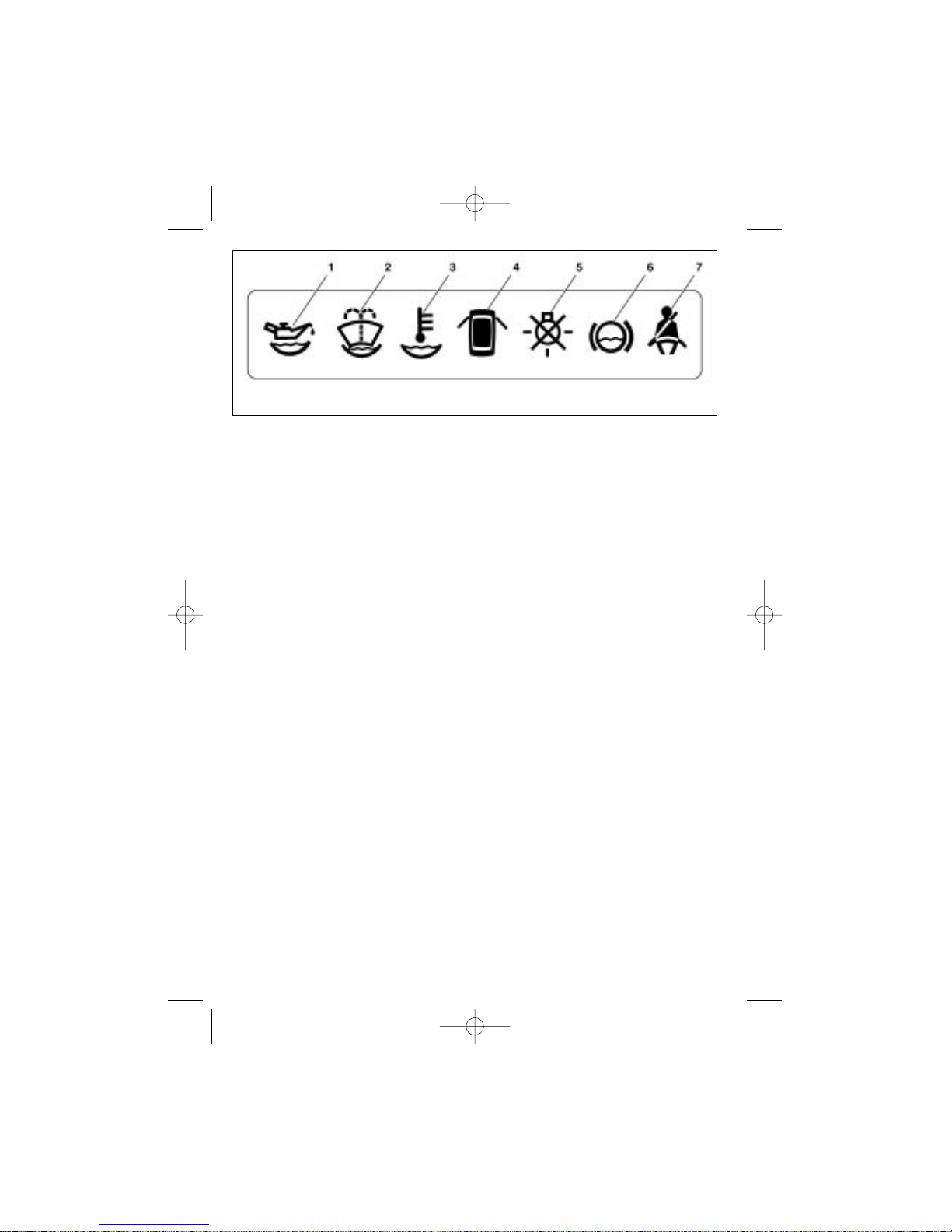
Warning! Some vehicle modifications may have no coolant level indicator.
4 — door ajar LED.
Lights up in red when a door is ajar.
5 — stoplight or side-marker
lights failure LED.
If the stoplight bulb is faulty the LED
lights up in orange when the brake
pedal is depressed. Also lights up if a
faulty side-marker bulb is activated.
6 — front brake pad wear indicator.
Lights up in orange when the brake
pedal is depressed if the brake lining
thickness is reduced to 1.5 mm. Goes
off at ignition switch-off.
7 — seat belt reminder LED.
Optional. Lights up in red if the driver’s seat belt is not fastened.
Modes of control module
The control module has the following modes:
— OFF;
— stand-by;
— start-up functional check;
— parameter check.
The module is OFF if there is no key
in the ignition switch. With the ignition
key in the «0» (OFF) position the mod-
ule enters the stand-by mode. If the driver’s door is open, «Key left in the ignition lock» error is generated and an
intermittent beep sound is heard for
about 5-7 seconds. To stop beeping,
close the door, remove the key or turn
it to position «I» (Ignition). With the key
in this position, the module enters
«Start-up functional check» mode. In
this mode all the visual and sound
alarms are activated for 3-5 seconds.
Then, after a second’s pause, the module enters «Parameter check» mode
and in the event of any failures, the
alarm is indicated as follows:
— LED of the failed parameter flashes for 5-7 seconds, then illuminates
continuously until the problem is fixed
or the ignition key is returned to position «0» (OFF);
— Beep sound for 3 seconds (simultaneously with the LED);
— if another problem occurs at the
same time, the latest problem will have
higher priority and its LED will start
flashing and a beep will be heard, the
LED of the previous fault illuminates
continuously.
Important!
The on-board control system displays
oil level with a 10 minute delay. This
delay is activated after the engine is
stopped if the ignition key remains in the
19
Fig. 21. On-board control system display
RE2115eng 23/04/2002 15:23 Page 19
Page 20
20
switch. It is required to allow the oil to
drip into the sump. During the 10 minute
delay the on-board control system indicates oil level as of the moment preceding the engine stop. If you remove the
ignition key, the oil level reading is reset.
In this case an attempt to restart the
engine within 10 minutes may cause
false low oil level alarm, which should
not be considered as an indication of the
lubrication system failure.
TRIP COMPUTER
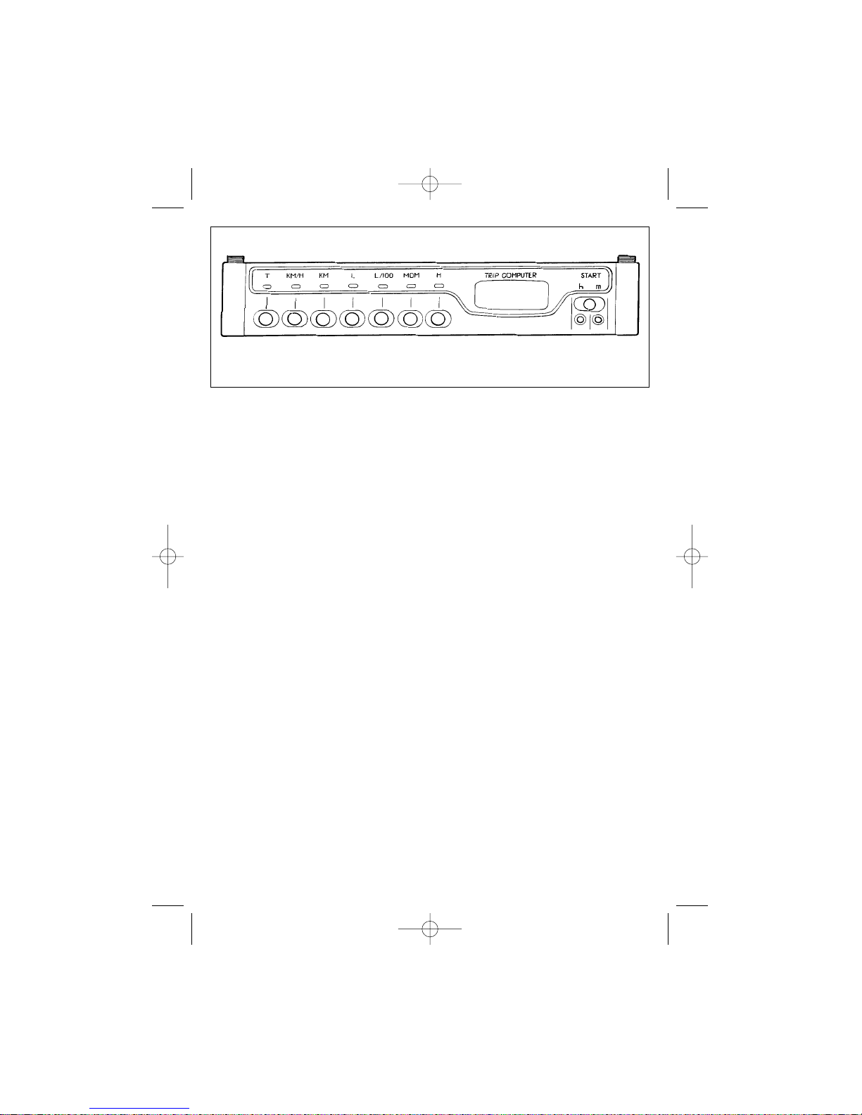
Fig. 22 shows a trip computer, which
may be fitted on some vehicles. It is
designed to take, store and display the
following parameters:
— fuel consumption (current, average, total);
— average speed;
— trip kilometers;
— current time;
— run time.
Depress the START button at the
beginning of a trip to reset all parameters except current fuel consumption
and current time. Depress a relevant
button to display one of the following
parameters:
Current Time («H» button) — indicates hours and minutes. Maximum up
to 23 h 59 m.
Depress button «h» or «m» below
the START button to adjust hours or
minutes. Depress and hold down a button to continuously increase the reading by 2 hours (minutes) per second.
Depress the START button to reset
minutes and seconds to zero.
Current Fuel Consumption
(«MOM.» button) — indicates fuel con-
sumption in L/100 km at a speed higher than 10 km/h, or in L/h at a speed
below 10 km/h.
Average Fuel Consumption
(«L/100» button) — indicates fuel con-
sumption in L/100 km starting from the
moment when the START button was
depressed.
Total Fuel Consumption («L» button) — indicates fuel consumption in
litres starting from the moment when
the START button was depressed and
up to 624.9 L.
Trip Kilometers («KM» button) —
indicates trip kilometers starting from
the moment when the START button
was depressed and up to 999.9 km.
Average Speed («KM/H» button)
— indicates average speed starting
from the moment when the ST ART button was depressed, less the time when
the vehicle was stopped with ignition
off.
Fig. 22. Trip computer
RE2115eng 23/04/2002 15:23 Page 20
Page 21
21
Run Time («T» button) — indicates
trip time starting from the moment
when the START button was depressed and up to 99 h 59 min, less the time
when the vehicle was stopped with ignition off.
Warning!
The trip computer LCD goes off at
ignition switch-off, however the
parameters are stored and the clock
continues to run. All information is
lost if the storage battery is disconnected.
If the system voltage drops to no
less than 6 volts, the stored parameters remain and the clock continues
to run.
STEERING COLUMN
STALK SWITCHES
Turn indicators and main/ low
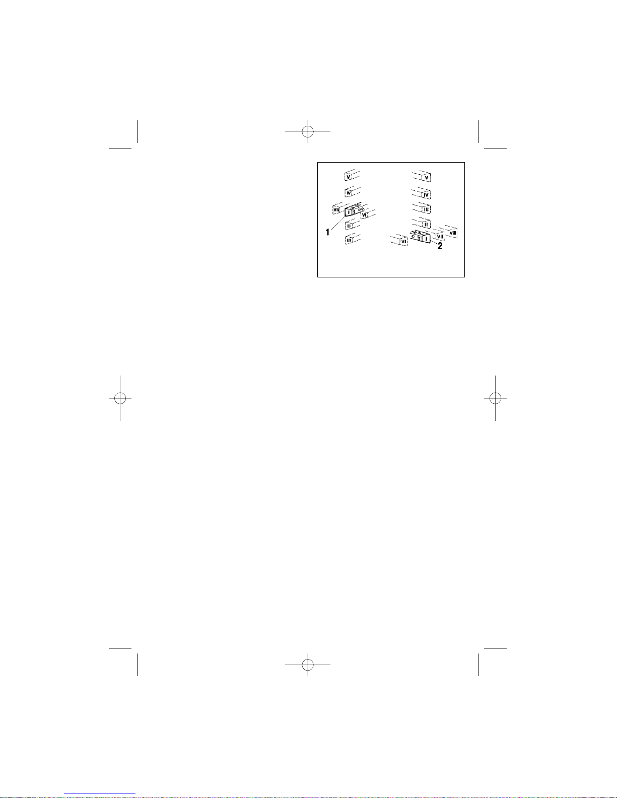
beam stalk switch 1 (Fig. 23) has the
following positions:
I — turn indicators are OFF; if headlights are energized, low beam is ON;
II — left turn indicator ON (non-fixed
position);
III — left turn indicator ON (fixed
position);
IV — right turn indicator ON (nonfixed position);
V — right turn indicator ON (fixed
position);
VI — (lever pulled in), main beam
ON, regardless of the exterior lights
switch position (non-fixed position);
VII — (lever pushed out), main
beam ON, if headlights circuit is energized (fixed position).
Windscreen/rear window wiper/
washer switch 2 has the following
positions:
I — windscreen wiper/washer OFF;
II — intermittent operation of wind-
screen wiper (non-fixed position);
III — intermittent operation of wind-
screen wiper (fixed position);
IV — low speed of windscreen
wiper;
V — high speed of windscreen
wiper;
VI — (lever pulled in) windscreen
washer is turned on (non-fixed position), windscreen wiper on;
VII* — rear window wiper ON (fixed
position);
VIII* — rear window wiper and
washer ON (non-fixed position).
DOOR MIRROR CONTROL
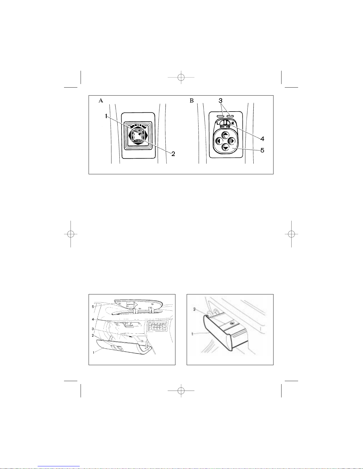
Control knob for door mirror adjustment is optional. It is located on the
floor tunnel. Tilt knob 2 (Fig. 24A) to
adjust mirror position vertically or horizontally.
To select a mirror rotate the knob by
90° (indicated by arrow mark 1). Since
Fig. 23. Steering column stalk
switches
______________
* For hatchback vehicles.
RE2115eng 23/04/2002 15:23 Page 21
Page 22
22
the knob has only two positions, one of
the circuits for the mirror position control (right or left) is always energized
when ignition is ON.
Some vehicles may feature an
optional variant of the door mirror control (Fig. 24B). To select a mirror for
adjustment shift selector 4. Depress
button 5 in indicated directions to adjust
the mirrors as suitable. Extreme selector positions energize RH or LH mirror
actuator circuits (indicator 3 illuminates
respectively). The selector middle position de-energizes the mirror actuator
circuits.
GLOVE BOXES
To open lid 1 (Fig. 25) of the lower
glove box, press lock knobs 2 together
and pull. Lamp 3 illuminates the glove
box when ignition is ON and the lid is
open. For access to the upper glove
box open the lower box lid (1) and push
lever 4 to release the upper lid (5) lock.
FRONT ASHTRAY
To use ashtray 1 (Fig. 26), pull it out.
To empty the ashtray, depress metal
strip 2 and take the ashtray out of the
socket. The ashtray is illuminated from
inside when the exterior light is on.
Fig. 24. Door mirror control
Fig. 25. Glovebox
Fig. 26. Front ashtray
RE2115eng 23/04/2002 15:23 Page 22
Page 23
23
LICENSE PLATE
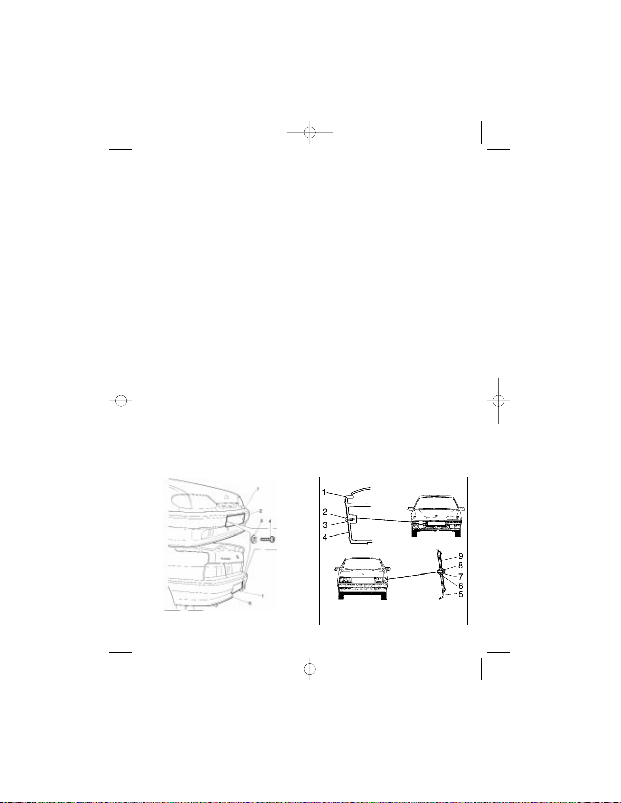
The vehicle has a set of fasteners
for mounting the license plate. License
plates 1 (Fig. 27a) on VAZ 2115 are
fastened directly to the front (2) and to
the rear (5) bumpers using two self-tapping screws 4 complete with washers
3.
On VAZ 2113 and VAZ 2114 front
license plate 4 (Fig.27b) is fastened to
front bumper 1 using two self-tapping
screws 2 with washers 3. To mount the
rear license plate insert plastic sleeves
6 into the vehicle’s body back wall (5),
place license plate 9 and fix it using
self-tapping screws 8 with washers 7.
VEHICLE THEFT
DETERRENT SYSTEM
(IMMOBILIZER)
Theft Deterrent System АПС-4
(APS-4) allows the engine start-up only
after a valid black key fob code has
been read, thus providing additional
protection against unauthorized access
to the vehicle.
The VTD system package includes
two black key fobs for daily use and
one red (programming) key fob. The
red key fob is used to activate the
immobilizer system and program the
original equipment (OE) black key fobs;
it is also used to program the replacement key fobs in case the OE key fobs
are lost, or program the system after
replacement of a faulty ECM or Immobilizer module. All key fobs bear the
marking «АПС-4».
The VTD system is activated during
the predelivery inspection.
Check to see that the Immobilizer
system has been connected and is fully
functional. To do that close the vehicle
doors except the driver’s door, get in
the car, and close the driver’s door . The
key reader LED should start flashing
twice a second. Put a black key fob in
front of the key reader. The key reader
LED will go off and two beeps will be
heard.
Fig. 27b. License plate mounting
OPERATING NOTES
Fig. 27a. License plate mounting
RE2115eng 23/04/2002 15:23 Page 23
Page 24

24
Now you may switch ignition on and
start the engine. The fuel injection pulses will be enabled.
Important! If the engine can be
started without using the black key
fob, the VTD system has not been
activated. Do not hesitate to request
your dealer to program and activate
the system during the PDI.
The immobilizer will be automatically armed after ignition switch-off
depending on the following: 1) if the driver’s door has not been opened or it
has been opened and not closed, the
system will be armed in 5 minutes, 2) if
the driver’s door has been opened and
then closed, the system will be armed
within 30 seconds after the door closing.
In both cases a beep sound of a rising pitch will be heard and the LED will
start flashing 15 seconds before the
system is armed.
If you do not wish to arm the system,
switch ignition on.
Immobilizer System Disarming
To disarm the Immobilizer system
activate the Reading Mode, which is
indicated by the key reader LED flashing twice a second, using one of the following procedures:
Open and then close the driver’s
door. This will activate the Reading
Mode for 1.5 minutes.
Cycle ignition ON/OFF. This will activate the Reading Mode for 10 seconds.
After the Reading Mode has been
activated place a black key fob in front
of the key reader. The LED will go off
and two beep sounds will be heard.
You may now switch ignition on and
start the engine.
Important! Never use a red key
fob to disarm the VTD system, for it
will disable fuel injection pulses.
Take the red key fob home for safekeeping. In case the red key fob is
lost after the VTD system has been
activated, the manufacturer disclaims warranty obligations related
to improper operation of the VTD
system or the ECM.
Emergencies
1. Black key fob is lost.
If a black key fob has been lost, we
recommend that you reprogram the
remaining black key fob. This will make
the lost key fob invalid. Then buy a new
black key fob and program both black
key fobs that you now have. Apply to
your dealer to perform programming
procedure of the OE and the new key
fob, or of two new key fobs.
2. Red key fob is lost.
If the red key fob is lost, it will be
impossible to program the black key
fobs. This means that you can continue
using the vehicle with remaining black
key fobs. However, should you lose
these key fobs or should the immobilizer module become faulty, it will be necessary to replace both the immobilizer
module and the ECM for the new ones.
In this case use a new red key fob to
activate the immobilizer system (to be
performed at your dealer’s).
3. Replacement of a faulty immo-
bilizer module.
After replacement of a faulty immobilizer module program the system (to
be performed at your dealer’s).
4. Replacement of a faulty ECM.
A faulty ECM may be replaced for a
new one (i.e. not programmed). After
RE2115eng 23/04/2002 15:23 Page 24
Page 25
replacement, the new ECM will allow
engine start-up without the fuel enable
signal from the immobilizer. To activate
immobilization, program the system (to
be performed at your dealer’s).
5. Engine won’t start.
If after disarming the system the key
reader LED flashes once a second and
the engine does not start up, the immobilizer system is faulty or there is no
connection between the immobilizer
module and the ECM. If the key reader
LED flashes once or twice and then
goes off, and the engine does not start,
the fault is not within the immobilizer
system.
Courtesy Light
The courtesy light goes off with a
delay after the door is closed providing
illumination for the driver during dark
hours.
To activate courtesy light put the
interior lighting switch in the OFF position. The courtesy light illuminates with
the driver’s door opening and stays on
while the door remains open. If ignition
is switched off, the courtesy light will
illuminate for another 12 seconds after
the driver’s door closing and then fade
within 4 seconds. If the door is closed
with ignition ON, the courtesy light will
die out immediately after the door closing. If the ignition key is turned into
position «I» while the courtesy light illu-
minates, the latter will go down immediately.
If you reopen the door while the
courtesy light is still on or is fading, the
courtesy light will re-illuminate and stay
on while the door is open, then it will
operate as described above.
USING IGNITION KEY AND
KEY FOBS
Use the following procedure to start
a vehicle, fitted with the VTD system:
1. After opening a vehicle’s door or a
brief ignition switch-on (if the courtesy
light switch in the driver’s door is faulty)
the immobilizer Reading Mode will be
activated for 30 seconds — the key
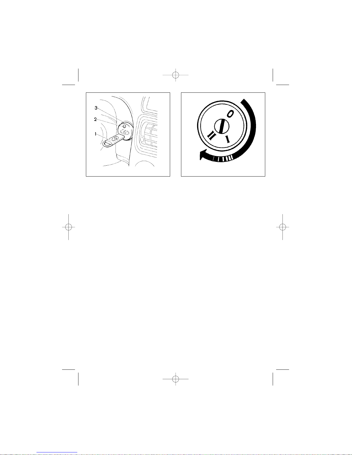
reader (3) LED (2) (Fig. 28) will flash at
a double rate.
25
Fig. 28. Instrument panel (detail) Fig. 29. Ignition switch
RE2115eng 23/04/2002 15:23 Page 25
Page 26
26
2. During this period place a black
key fob (1) within 13 mm from the key
reader. The key reader LED should illuminate for 2 seconds and then go off,
indicating that the immobilizer has read
and accepted the key fob code. After
that the immobilizer module will send a
signal to the ECM enabling the fuel
injection pulses.
To start the engine, turn ignition key
1 (Fig. 29) from position «I» (Ignition) to
position «II» (Starter—Engine Cranking).
The ignition switch has a blocking
device, which inhibits starter activation
if the engine is running. If the first
attempt to start up the engine fails, try
again by switching from position «I» to
position «0» (OFF) and then again to
position «II» (Cranking).
To remove the ignition key put it into
position «0». Removing the key will
engage the steering wheel lock.
Never leave the key in the ignition
switch to avoid storage battery discharge!
ENGINE START
To start an engine (warm or hot
engine with the coolant temperature
over 90°C) turn the ignition key into «II»
position (Cranking). Do not depress the
accelerator pedal.
During cold seasons when the temperature is below zero we recommend
you to depress the clutch pedal before
attempting an engine start in order to
reduce the load on the starter motor.
If the engine fails to start at first
attempt, switch ignition off, wait 30 seconds, then try to activate the starter
again. It is not recommended to switch
on the starter for more than 10 seconds. After starting the engine release
the ignition key and let it slide into position «I» automatically.
Cold start
1. Set the gear lever in neutral position. At low ambient temperatures also
depress the clutch pedal.
2. Insert the ignition key and activate
the starter motor. If the first attempt to
start the engine fails, switch ignition off,
and in 20-30 seconds reactivate the
starter motor. It is not recommended to
keep the starter motor running for more
than 10-15 seconds.
Do not depress the accelerator pedal
while starting the engine.
3. After the engine start-up, release
the ignition key, which will return to
position «I» automatically (Fig.27). As
soon as the engine runs steadily,
smoothly release the clutch pedal.
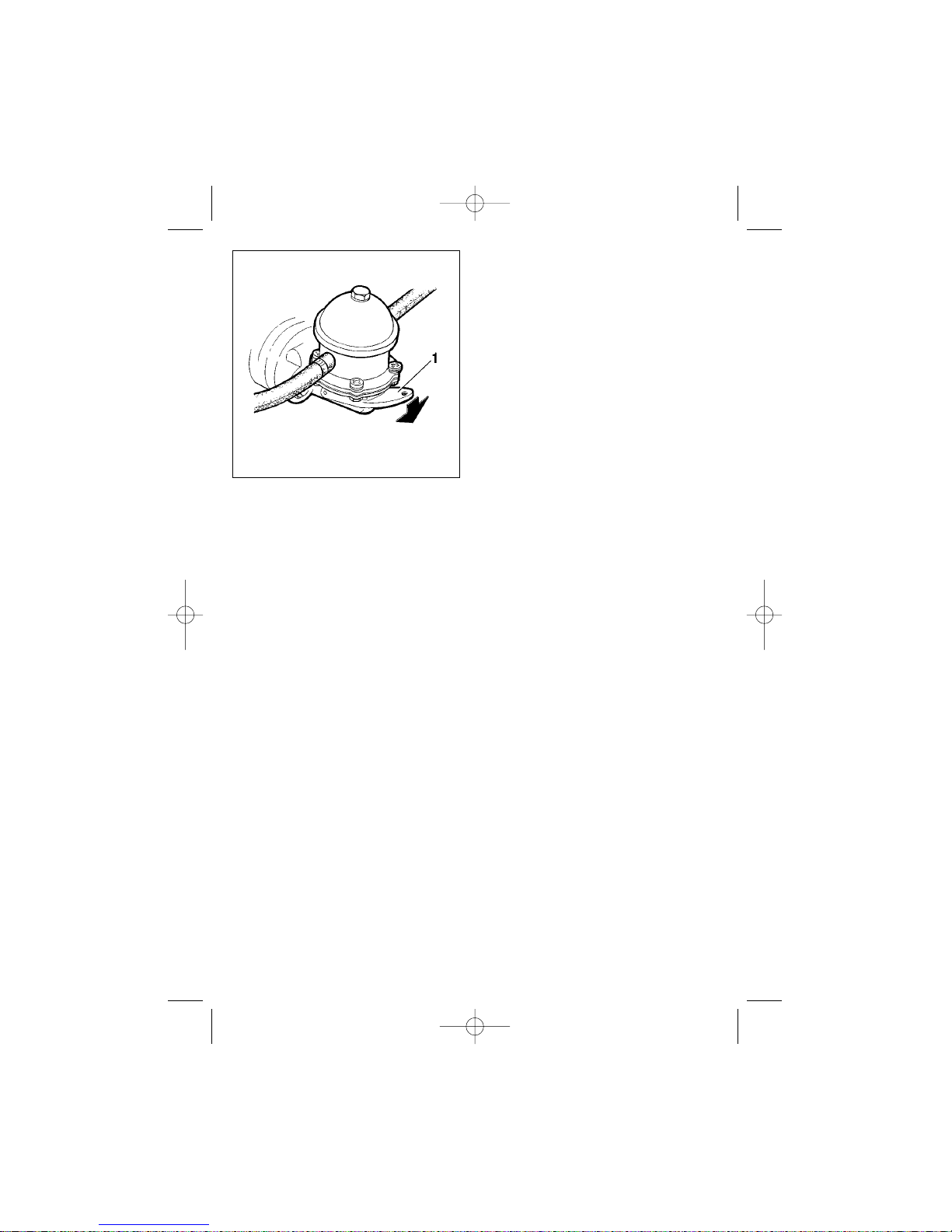
After a long parking period we recommend you to prime fuel into the float
chamber of the carburetor engine
before attempting to start the engine.
Fig. 30. Fuel pump
RE2115eng 23/04/2002 15:23 Page 26
Page 27

27
To prime the fuel, press lever 1 (Fig.
30).
The vehicle features high power
ignition system, for that reason never
start the engine by arcing a disconnected HT lead to the spark plug, never disconnect HT leads or check HT circuits
for spark with the engine running, since
it may damage HT components and
render the ignition system inoperative.
Always remember that the exhaust
gasses are noxious. Therefore, the
premises where the vehicle is started
and warmed up must be well ventilated.
DRIVING THE VEHICLE
Never use the starter motor to set the
vehicle into motion.
We recommend starting the vehicle
with the engine warmed up. If in cold
weather or after long parking there is
no possibility for you to warm up the
engine before setting to motion, and
you need to take off immediately, start
driving in a low gear and with low
engine speed. As the temperature of oil
in the gearbox rises, shift to higher
gears.
For more confident gear shifting
remember the difference between the
1st and the reverse gear shift patterns.
Select the reverse gear with a 3 seconds pause after depressing the clutch
pedal and only with the vehicle fully
stopped. To select reverse gear, move
the lever from neutral position just like
for the 1st gear, then push it forward
harder to a stop.
The engine is distinguished for its
low noise operation. Timely shift gears
to avoid engine high speeds. This helps
to extend vehicle life and increase fuel
economy.
Always try to evaluate the road
before starting a cornering manoeuvre.
Slow down the vehicle depending on
the cornering radius and road surface,
then «negotiate» the corner gradually
increasing the engine speed. This will
help to keep the hold even on an icy
road. Avoid hard braking or abruptly
releasing the accelerator pedal during
cornering, for in this case the wheels
grip on the road may fade and you will
lose control over your vehicle.
Where possible, drive without heavy
acceleration or deceleration, which add
to tyre wear and fuel consumption. Fuel
consumption is also affected by low
tyre pressure, foul or worn spark plugs
and use of engine oils of higher viscosity grades than those recommended.
Likewise, fuel consumption increases when towing a trailer. Furthermore,
towing induces loads on the vehicle
body, engine and transmission thus
reducing their service life.
After driving over puddles, vehicle
wash or long driving on wet roads,
when water is likely to get into the
wheel brake mechanisms, apply the
brakes gently on the move in order to
dry up the discs, drums and linings.
When driving over puddles reduce
your speed to avoid aquaplaning,
which may result in side skidding or
loss of steerability. Worn tyres increase
the probability of aquaplaning.
To avoid engine failure due to water
coming into cylinders through the air
cleaner, do not cross pools over 300
mm deep (i.e. water reaching vehicle
underbody). Cross pools at a minimum
possible speed to avoid waves coming
over the bumper.
Do not exceed vehicle load specifications given in the present manual.
RE2115eng 23/04/2002 15:23 Page 27
Page 28
28
Overloading may damage the suspension, cause tyre wear and loss of vehicle stability. Overall cargo weight,
including cargo at the roof rack, should
not exceed 50 kg.
Never drive at a high speed on
rough roads, since sharp shocks may
damage the suspension or the underbody.
BRAKING AND PARKING
Brakes design ensures efficient
braking. Nevertheless, always try to
brake gently and avoid hard braking.
Never switch off ignition or take the
key out of the ignition switch while driving. When the engine is off, no vacuum is supplied to the power brakes,
hence, a higher force is required on the
brake pedal to stop the vehicle.
Moreover, if the ignition key is
removed, the steering wheel will be
locked and you lose steering control.
In the event of a break or fault developing in one brake circuit, the other circuit ensures an effective stop of the
vehicle. When this happens, the pedal
travel increases and braking performance fades, which at the first instant
can be interpreted as a complete brak-
ing system failure. Should this be the
case, do not release the pedal and do
not depress it repeatedly — it will only
result in a longer braking path. Instead,
hold the pedal down for maximum braking efficiency.
The antilock braking system (ABS)
is an optional part of car equipment,
which prevents wheel lock-up during
braking and, as a result, retains the
vehicle’s steerability and minimum
braking distance practically under any
driving conditions. However, on loose
surfaces (gravel, sand or snow) the
braking distance may somewhat
increase, as compared to the braking
distance with the wheels locked up.
The antilock function becomes
active at speeds above 8 km/h and is
felt as slight pulsation of the brake
pedal accompanied by light noise coming from the ABS components. If the
ABS tell-tale illuminates (except during
self-testing at ignition switch-on), it indicates a fault within the system, which
must be eliminated at your dealer’s. A
faulty ABS does not in any way incapacitate power braking.
To allow unhindered operation of the
ABS, do not fit the vehicle with different
size tyres.
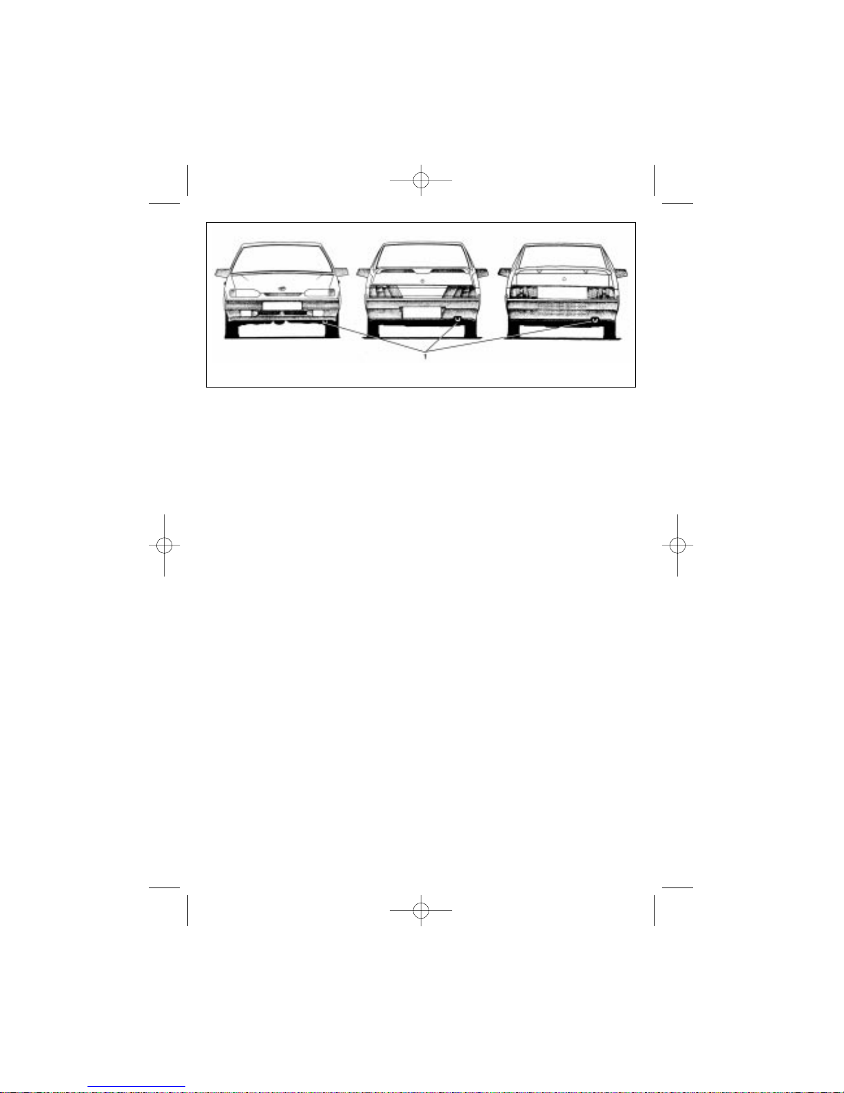
Fig. 31. Towing eyes
RE2115eng 23/04/2002 15:23 Page 28
Page 29
29
If you happened to stop on an
upward or downward slope, apply the
handbrake and engage first or reverse
gear, respectively.
TOWING
For towing your vehicle attach the
tow-rope only to the front or rear towing
eyes (1) (Fig. 31) provided. On the
towed vehicle turn the ignition key to
position «I» and switch on the hazard
warning flashers (in dark hours also
switch on side-markers, or attach a
breakdown reflecting triangle if inoperative), as required by Traffic Regulations.
Towing should be done smoothly,
without jerks or fast cornering.
Never use a rope to tow a vehicle on
an icy road!
«RUN-IN» PERIOD
Over the first 2000 km:
1. Check tyre pressure and inflate
the tyres to recommended value before
each trip.
2. Do not exceed vehicle’s maximum
speed limits listed in table 1.
3. Timely, following the road situation, shift to lower gears, to avoid
engine overloading.
4. Do not change the oil filled by the
manufacturer.
5. Do not tow a trailer unless
absolutely necessary.
Table 1
Speed limits for a new car, km/h
Total Gear
trip, km 1st 2nd 3rd 4th 5th
0-500 20 40 60 80 100
500-2000 30 50 70 90 110
NOTES ON USING
VEHICLES WITH
INJECTION ENGINES
If the light « » (CHECK ENGINE)
comes on with the engine running, it
does not mean, that the engine has to
be stopped immediately, — the control
module has back-up modes to allow
engine operation close to normal.
However, the vehicle must be taken to
your dealer at the earliest opportunity
to detect the cause of the MIL illumination.
Only unleaded fuel should be used for
injection vehicles fitted with the catalytic
converter and oxygen sensor to ensure
correct functioning of the engine. The
use of leaded fuel will quickly ruin these
components and result in smoky exhaust
and poor fuel economy.
Use leaded fuel only for carburetor
engines.
The catalytic converter is an expensive device designed for environmental
protection. It may be damaged by misfires, since, in this case, unburnt fuel will
get into the catalyst, resulting in overheating and ceramic cracks. Therefore,
in case of noticeable misfire (engine
misses or car jerking) stop the engine
and remove the cause of misfire.
Regularly carry out all maintenance operations for the ignition system specified in
the service manual.
Never start the engine by towing or
use the starter motor to drive the vehicle.
Avoid parking the vehicle on dry
grass or other flammable materials,
which may present a fire hazard if the
catalyst is at its working temperature.
On engines with fuel injection system the ECM activates the fuel pump
for 2 seconds at ignition switch-on. If
you disconnect and then reconnect the
storage battery cable on vehicles with
the ECM model MP7.0, during the first
RE2115eng 23/04/2002 15:23 Page 29
Page 30
30
attempt to start up the engine the fuel
pump will be activated only with the
starter motor activation. At subsequent
attempts the fuel pump will be activated
with ignition switch-on. However, in
case of three consecutive failures to
start up the engine, the fuel pump will
once again be activated only with the
starter motor activation.
If you disconnect and then reconnect the storage battery cable on vehicles with the ECM model MP7.0, which
do not have the VTD system (immobilizer), wait 5 second between ignition
switch-on and the first attempt to start
the engine.
INTERIOR VENTILATION
AND HEATING CONTROL
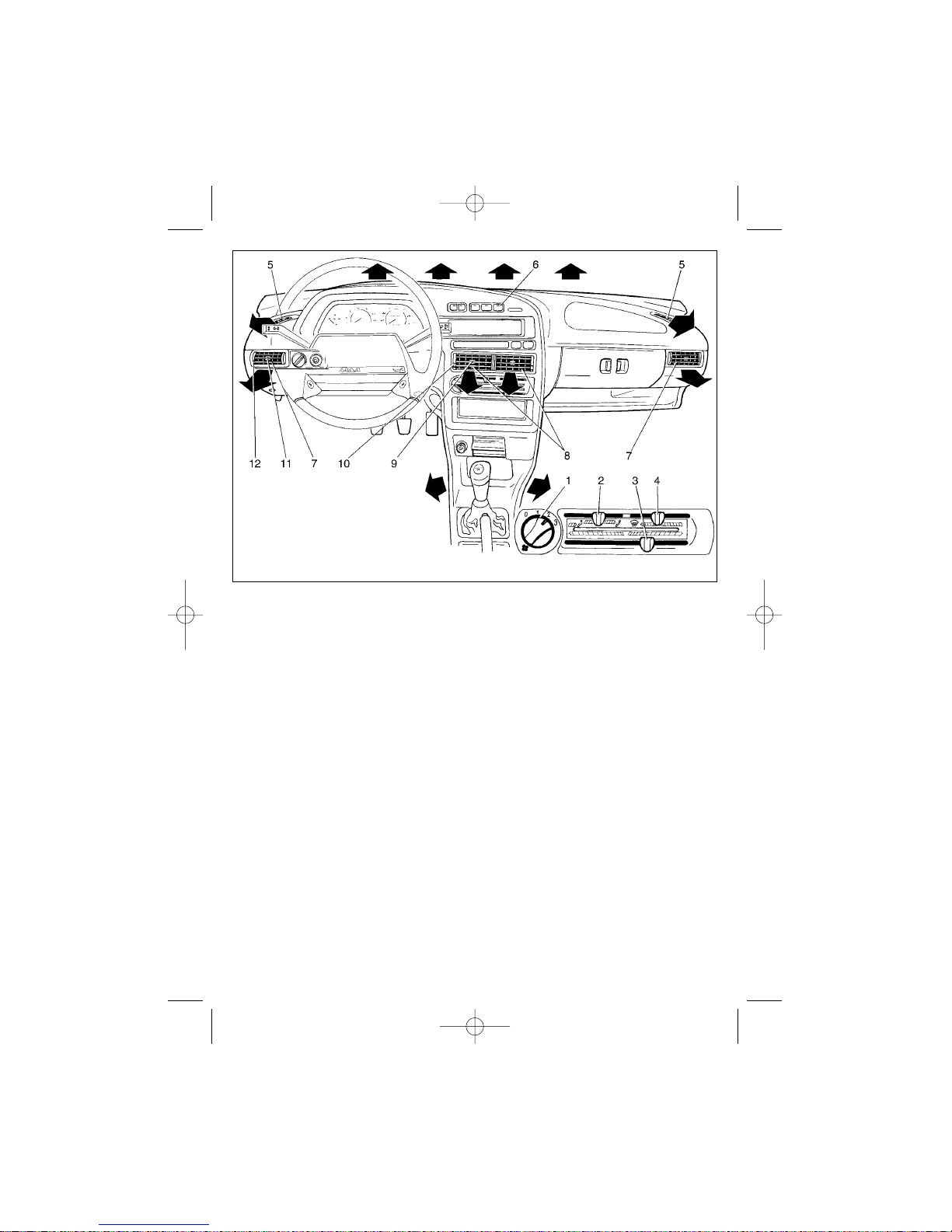
The interior ventilation and heating
controls are illustrated in Fig.32.
Slide knob 2 to direct air into the driver’s and passenger’s foot wells, or
through the central (8) and side (7) registers. Use shutter control levers 9 or 11
to redirect the air flow. To heat the supplied air, slide knob 3, which controls
the heater valve. Adjust air stream
intensity by selecting a desired position
of switch 1.
By sliding control lever 4, you can
adjust intensity of the air stream coming onto the windscreen through the
upper registers and onto the side windows through registers 5. For maximum airflow shut the central and side
registers using slide-controls 10 and
12, then slide knob 2 rightwards and
knob 4 leftwards. Direct cold air on the
windscreen and side windows to
demist them, for defrosting also slide
knob 3 to the right.
Fig. 32. Interior ventilation and heating system
RE2115eng 23/04/2002 15:23 Page 30
Page 31

31
The rear window heating for demist-
ing/ defrosting is turned ON by switch
6.
SAFE DRIVING
INSTRUCTIONS
Observe the rules laid down below
to ensure your safety on the road and
maintain sound condition of the vehicle.
At the wheel
Efficient driving technique depends
on the driver’s good posture, which can
be described as follows: the driver
leans back firmly against the backrest
with his legs slightly bent in the knees
when the pedals are fully depressed
and with both his hands on the steering
wheel also slightly bent. Try to seat
firmly but not stiffly, otherwise you will
get tired fairly soon.
Before the trip
Make the following checks before
each trip:
1. Check tyre pressure and inflate as
necessary. A pressure difference as
small as 0.2-0.3 kgf/cm
2
may impede
drivability and cause skidding at braking.
2. Check oil level and top up if nec-
essary.
3. Check coolant, braking fluid and
washer fluid levels and top up as necessary.
4. Check exterior illumination for
correct operation.
5. Check windscreen wiper/washer
and the parking brake.
6. Carefully inspect the parking
ground. Spillage of oil or other fluids
indicates leaks in the car systems.
Correct the problem.
7. Check brakes for correct operation while driving out from the parking
lot.
Fording
Ford with caution, since water may
hide pits or other obstacles, which may
damage wheel disks and suspension
components. Do not cross fords over
0.3 m deep (water coming over vehicle
bumper). Proceed with caution to avoid
waves coming onto the radiator grille,
for it may cause water suction into the
engine through the air intake, and
eventual engine failure. Purge the air
cleaner with pressurized air after the
fording if necessary.
The ignition system components
may become wet and cause engine
stoppage if driven in heavy rain. To
avoid moisture condensation on the
ignition system components apply a
spray type water repellant.
The first few minutes after a rain
starts present special hazard of wetted
dust, which forms a slippery film on the
road, thus reducing tyre traction.
Gently apply brakes from time to
time to dry up brake disks and drums,
which may become ineffective if wet.
Switch windscreen wiper to maximum speed during nonstop overtaking.
This will help you to have unhindered
visibility even if there are water splashes coming from under the wheels of the
vehicle you are passing. Do the same if
another vehicle is passing you by.
Do not overtake other vehicles if the
water mist limits visibility.
Increase the distance to the vehicle
ahead and slow down to avoid driving
in the water mist.
RE2115eng 23/04/2002 15:23 Page 31
Page 32

32
Slow down if driving by a sidewalk
and do not splash water on pedestrians.
Winter driving
Winter driving requires special caution! We recommend you to use winter
tyres on all wheels.
Be careful while driving on wet or
slippery roads, avoid hard braking, do
not step on the accelerator pedal or
release it abruptly. Steer your vehicle
smoothly without sudden turns of the
steering wheel. Decelerate gradually
timely shifting to lower gears and gently applying the brakes. If the vehicle
starts to skid, turn the wheel in the
direction of skidding and stabilize your
vehicle with gentle steering and accelerator pedal application. Never release
the accelerator pedal if the vehicle
starts to skid, this may cause your vehicle to spin around.
Ice is very likely to form at the crossroads due to stop-and-go driving, which
causes wheel spinning. Therefore,
always think ahead and start decelerating while you are still on a dry road.
It may appear rather difficult to set
your vehicle into motion on a slippery
road. Select the second gear and gradually releasing the clutch pedal
increase the engine speed. For safe
cornering shift into the first gear and
start the manoeuvre with little acceleration avoiding wheel slip.
Mountain driving
Timely select lower gears and avoid
engine tickover or vehicle jerking when
driving uphill. Use engine braking and
gently apply service brakes to go down
a long descent. Select a correct gear to
avoid engine overspeeding and subsequent failure. Never go downhill using
only the service brakes with the engine
off and the clutch disengaged. When
the engine is off, no vacuum is supplied
to the power brakes, and the disengaged clutch will make the braking fluid
boil. Mind also that the higher you climb
the lower is the braking fluid boiling
point. Braking fluid boiling in the wheel
cylinders causes complete failure of the
service braking system felt as a spongy
pedal.
If you want to stop at a parking place
on a mountain road, do not switch the
engine off immediately, for it will cause
coolant boiling; allow the engine to idle
for 1-2 minutes — this will make starting the engine easier.
Stay to the right side of a mountain
road. Narrow and winding roads
require greater attention and caution.
Use horn and headlights when
approaching «blind» turns. If you need
to stop on the up- or downhill, turn the
steering wheel so that in case of the
vehicle’s accidental movement it would
steer into a kerb or other obstacle.
Do not go uphill on a wet road until
the preceding vehicle reaches the top.
Using brakes
Learn to brake smoothly without
wheel lock-up. It is a good practice to
brake smoothly while shifting to lower
gears; this helps to maintain directional
stability even on a slippery road,
increases fuel economy, and extends
tyre and brake pads service life.
An experienced driver slightly
depresses the brake pedal several
times until the stoplights illuminate to
worn other drivers of the impending
deceleration.
RE2115eng 23/04/2002 15:23 Page 32
Page 33

33
If the vehicle steers sideways while
braking with the fully functional suspension, correct wheel alignment and normal tyre pressure, check the braking
system.
Select a free passage on the road to
test the braking system of vehicle you
never drove before. Try braking at 40,
60 and 80 km/h.
Do not park your vehicle for a long
period with the parking brake applied to
avoid brake pad-to-drum binding.
To prevent brake pad-to-drum binding as a result of wet road driving or
sharp temperature alterations dry the
brakes by smooth service brake application on your way to the parking lot.
Only after that you may apply the park-
ing brake and leave your vehicle for a
long period.
Tyres and safe driving
Sharp acceleration/deceleration,
low/high tyre pressure, untimely tyre
rotation, unbalanced wheels, driving at
high speeds on rough roads or incorrect wheel alignment visibly reduce tyre
service life. Driving with worn tread pattern on a rainy day is dangerous —
there are no sipes, which provide passageway for the water being expelled
from under the tyre, and the tyre begins
to aquaplane. Use winter tyres (M+S
type) with or without spikes to drive in
winter.
RE2115eng 23/04/2002 15:23 Page 33
Page 34
This section describes the operations to be regularly carried out
between maintenance checks as prescribed by the Service Manual.
Check on a regular basis the rubber
boots of the steering rack, ball bearings, gearshift rod, front axle balljoints
and the steering rod joints. Adamaged
boot will allow dust, water and mud into
the joint reducing its service life.
Replace a damaged boot or reshape a
twisted one.
LUBRICATION SYSTEM
An engine usually consumes a certain amount of oil during operation. This
amount depends on your driving techniques, and is predetermined by the
engine load and speed. During the runin period oil consumption is higher than
regular.
Therefore, regularly check oil level,
especially before long journeys.
Check the oil level on a cold engine,
when it is off, and top up as necessary.
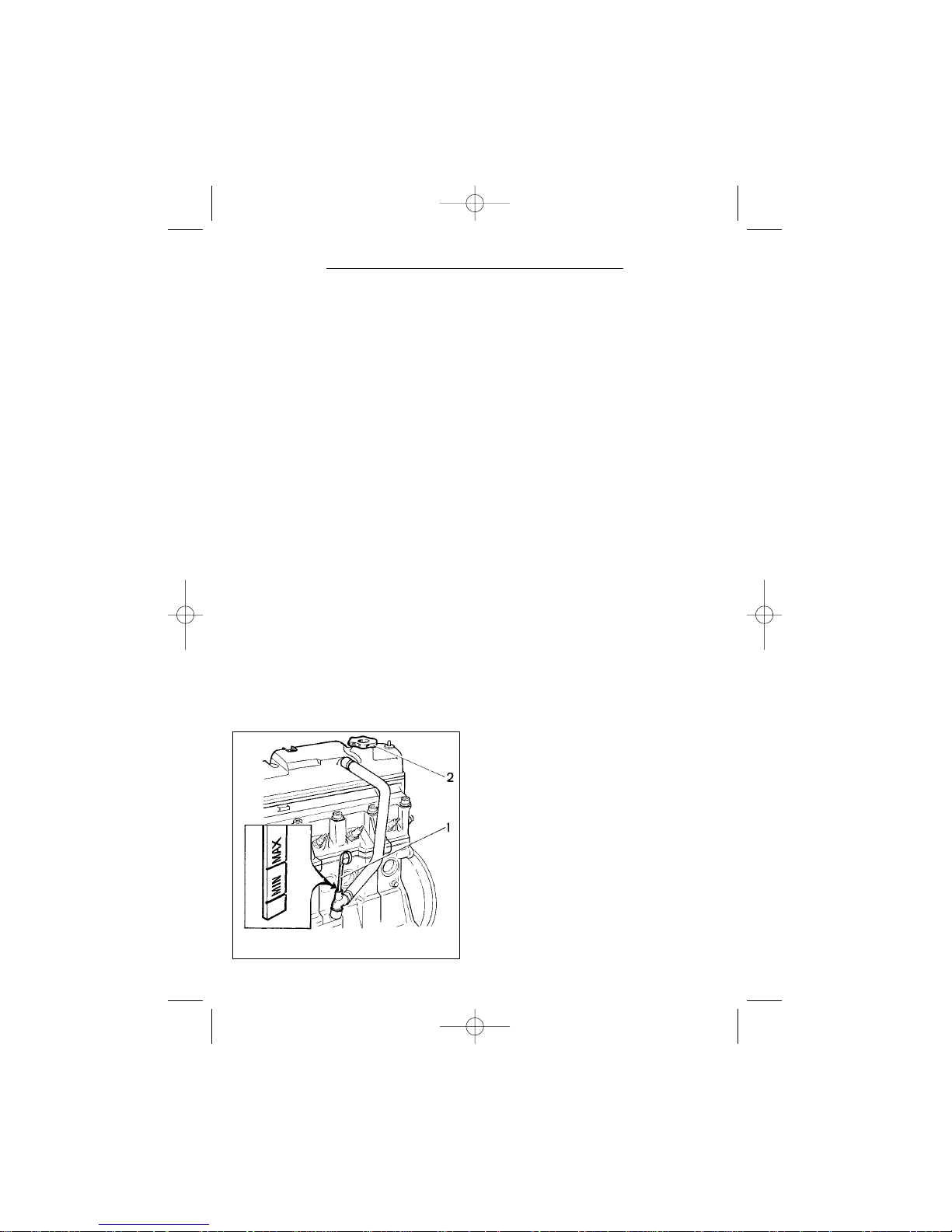
The oil level must be between the
«MIN» and «MAX» marks of oil dipstick
1 (Fig.33). Refill the engine through the
filler closed with cap 2.
Do not fill oil above the «MAX»
mark. Otherwise it will be drawn
through the ventilation system into the
combustion chambers and then
released into the ambient with the
exhaust gasses. At the injection
engines fitted with a catalytic converter
oil in the exhaust may destroy the catalyst.
ENGINE COOLING
SYSTEM
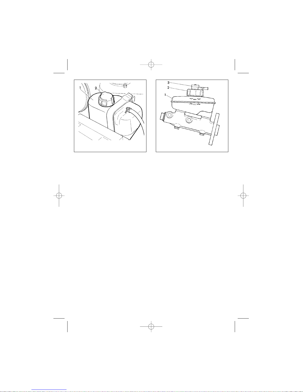
Coolant level should be 25-30 mm
above the «MIN» mark on the transparent body of expansion tank 1 (Fig.34).
Check the coolant level or open the
expansion tank cap (2) only when the
engine is cold. After refill, tighten the
expansion tank cap firmly, since when
the engine is running and warmed-up,
the expansion tank is under pressure.
If you have to add coolant frequently, check the cooling system for leakage and remedy the situation. As an
exception, the cooling system may be
topped up with clean water, though you
should never forget that in this case the
freezing temperature will be higher.
Therefore, make necessary repairs of
the system as soon as possible and
refill it with the coolant.
Warning! Note that coolant is poisonous! It must be stored in a tightly sealed container beyond the
reach of children. Do not use clean
water instead of coolant.
34
Fig. 33. Checking the engine oil level
SERVICE AND MAINTENANCE
RE2115eng 23/04/2002 15:23 Page 34
Page 35
BRAKE SYSTEM
The brake fluid level is checked
visually against the marks on reservoir
1 (Fig.35) made of translucent plastic.
With new brake linings and cap 2
removed, the fluid level should reach
the «MAX» marking.
When checking the brake fluid level,
always check correct operation of the
low fluid level sender by pressing the
central part of protective cap 3 — with
ignition ON, a respective tell-tale light
should come up on the instrument
panel.
The brake system failure warning
light comes up when the fluid level is
below the «MIN» mark, which in the
event of only slightly worn or new brake
linings indicates hydraulic leaks somewhere in the system. Before topping-up
fluid, be sure to eliminate any leaks.
Pay special attention to the flexible
hoses, which suffer from exposure to
water, mud, sand and salt. In case of
small cracks, or hose bulging when the
brake pedal is depressed, replace the
hose for a new one.
Refill brake fluid every three years
for the following reason: the brake fluid
absorbs moisture from the ambient air,
resulting in its lower boiling point. Apart
from that, water present in the brake
fluid may corrode some of the braking
system components.
Note that brake fluid is poisonous! It
must be stored in a tightly sealed container beyond the reach of children.
Avoid spilling brake fluid on the
paintwork to prevent its damage.
STORAGE BATTERY
MAINTENANCE AND
RECHARGING
The electrolyte level in the battery
should be between the «MIN» (Fig.36)
and «MAX» marks on the translucent
battery case. If there are no marks, the
level must be at the lower edge of the
filler neck. If the electrolyte level is
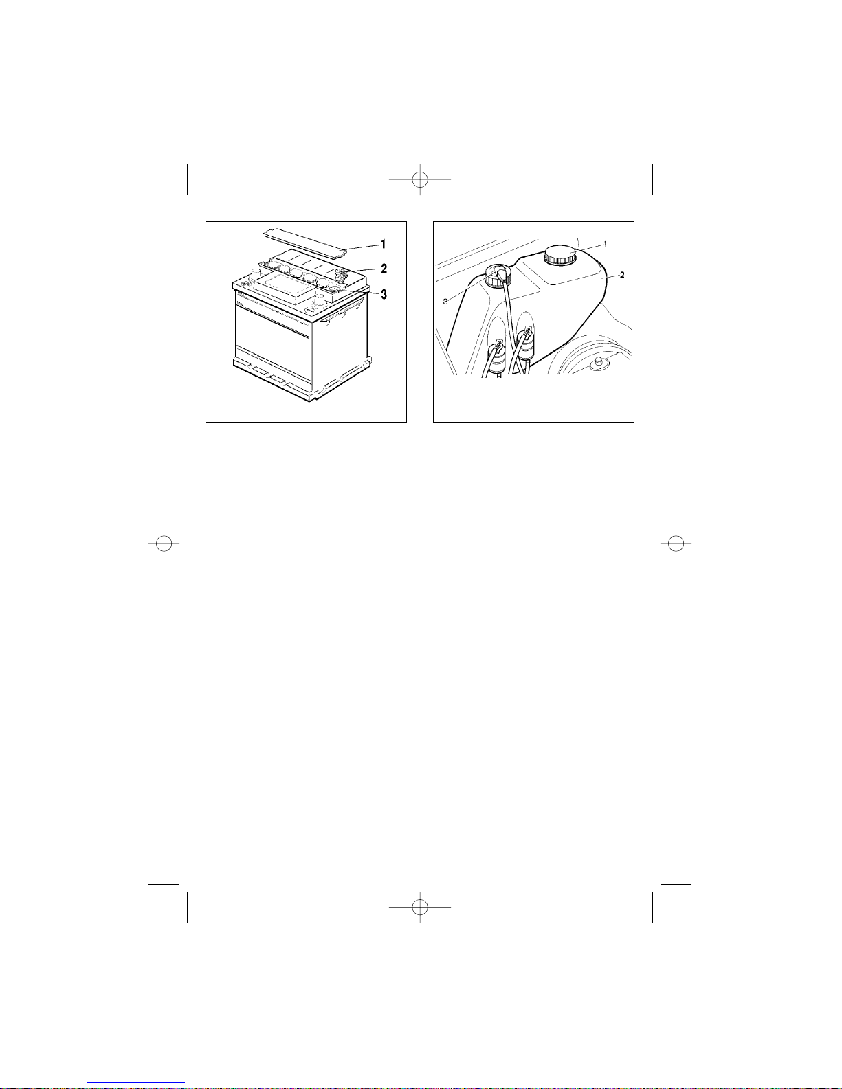
below that required, remove cover 1,
unscrew caps 2 and top up distilled
water to the battery through holes 3.
Make sure, the vents are not blocked,
then refit caps 2 and cover 1.
35
Fig. 34. Checking the coolant level Fig. 35. Checking the brake fluid level
RE2115eng 23/04/2002 15:23 Page 35
Page 36
36
Afterwards, wipe off any spills of electrolyte and battery external surfaces
with a clean cloth, soaked in a 10 per
cent solution of ammonia or baking
soda.
Do not fill the battery above required
level: electrolyte spilling through the
vents may damage the paintwork.
Always check that the battery terminals are tight and clean. Oxidized terminals or poor connection may cause
sparking and thus damage vehicle
electronics. For the same reason never
disconnect the storage battery with the
engine running to check the alternator
operation.
When installing the battery, ensure
correct polarity of connections according to the markings (positive terminal is
also bigger in size than negative).
Charging the battery on the vehicle
requires disconnection of the red lead
from the alternator. The storage battery
is connected to the alternator terminal
30 by the positive cable (terminal «+»).
We recommend you to remove the
battery from the vehicle before recharging it.
WASHER FLUID
The washer fluid in container 2 (Fig.
37) should be maintained on a reasonable level to prevent possible activation
of low level sender 3. Top up washer
fluid through the hole, normally closed
by cap 1.
Fill the fluid reservoir of the washer
system with a mixture of water and an
appropriate washer fluid in proportion
indicated on the package. Clean water
may be used in warm weather.
Adjust the windscreen washer sprinkler so as to make water come onto the
upper part of the wiped area. For this
purpose insert a needle into the sprinkler orifice and using it as a lever adjust
the sprinkler ball head.
SPARK PLUGS
The spark gap «A» (Fig.38) should
measure 0.7-0.8 mm (1.00-1.15 mm for
injection system). Adjust the gap by
bending the side electrode only.
To ensure reliable start-up at cold
temperatures replace the spark plugs
for the new ones, even if the currently
Fig. 37. Windscreen/headlight
washer container
Fig. 36. Storage battery
RE2115eng 23/04/2002 15:23 Page 36
Page 37
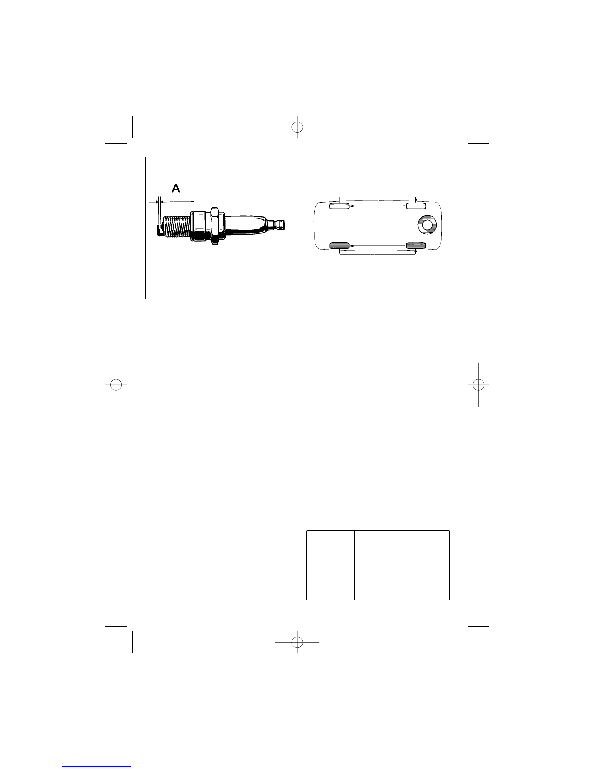
installed spark plugs are in good condition. The latter can be put away for
safekeeping and used during the summer time.
Always check that the HT leads are
clean and tightly connected to the
spark plugs, distributor sensor, ignition
coil or ignition module (for injection system). Replace rubber boots if damaged.
WHEELS AND TYRES
Maintain tyre pressure at the level,
specified in table 2. Driving the vehicle
with tyre pressure other than recommended results in accelerated tyre
wear, increased fuel consumption, poor
vehicle stability and driveability. In case
of repeated pressure drops, check for
air leaks through the valve. If necessary, tighten the valve core or replace
it.
If pressure continues to drop with
the valve fully functional, repair the tyre
using the sealant supplied with the
vehicle and strictly observing the
instructions.
All work related to the wheel beading or balancing should be entrusted to
your dealer.
Apply to your dealer for balancing
the wheels after installing new tyres.
Rotate tyres as shown in diagram 39
to ensure their uniform wear.
Avoid driving the vehicle with the
wheels rubbing against the kerbstone
or driving at a high speed on a rough
road (with pits and bumps), for it may
damage the wheel rim and result in loss
of wheel balance or sealing of tubeless
tyres. Should you notice any vibrations
while on the road, apply to your dealer
to check wheel balance.
Table 2
Tyre Pressure
Tyre Front and Rear Wheels
MPa (kgf/sq.cm)
165/70 R 13 0.2 (2.0)
175/70 R 13 0.19 (1.9)
37
Fig. 39. Tyre rotationFig. 38. Spark plug
RE2115eng 23/04/2002 15:23 Page 37
Page 38
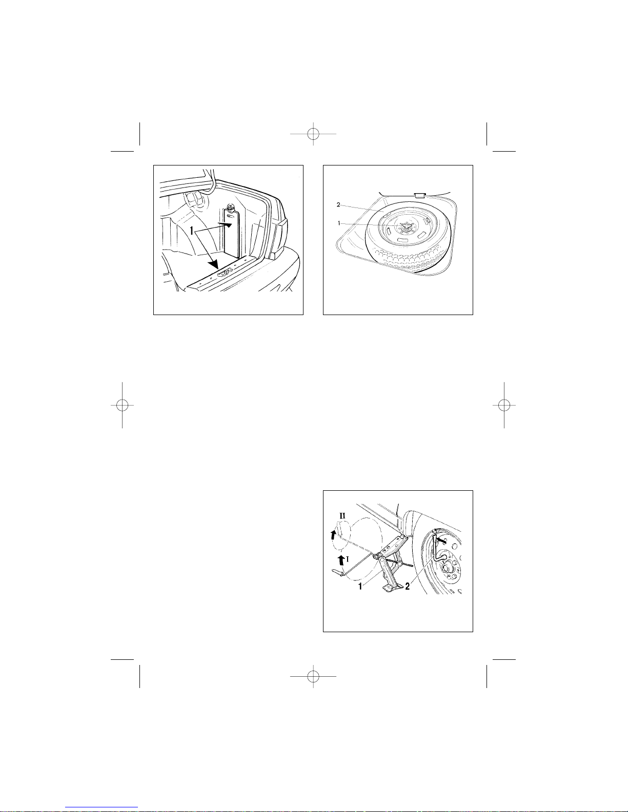
Wheel changing
To replace a road wheel:
— place the vehicle on level ground
and apply the handbrake;
— remove covers 1 (Fig. 40) or mat
and take out a pump, jack, tools and
replacement wheel. Spare wheel 2
(Fig. 41) is located in a will of the boot.
Remove the mat, then the cover and
unscrew bolt 1 to take out the wheel.
— remove the wheel cap (if installed);
— slacken each nut of the affected
wheel one turn using box wrench 2
(Fig.42);
— locate jack 1 head so that the
nearest to the wheel sill rim enters the
notch in the jack head and the jack
base is exactly beneath it. Turn the jack
handle (Position I) until the wheel is
some 50-60 mm clear of the ground. If
the handle cannot be turned 360°, use
the smaller radius for rotation (Position
II);
— remove the bolts and lift off the
wheel. Position the spare wheel, fit the
bolts and tighten them uniformly using
the x-pattern;
— lower the vehicle to the ground
and remove the jack. Fully tighten the
bolts, check the tyre pressure and
pump up as necessary;
Stow away the tools into the boot,
fasten them with elastic straps and
replace covers.
FUSE REPLACEMENT
Use only fuses listed in Appendix 3
for replacement.
Fuses 1 and relays 2 are located in
block 3 shown in Fig.43. The fuse/relay
38
Fig. 42. Car jacking for wheel
replacement
Fig. 41. Spare wheel well Fig. 40. Tool compartments
RE2115eng 23/04/2002 15:23 Page 38
Page 39
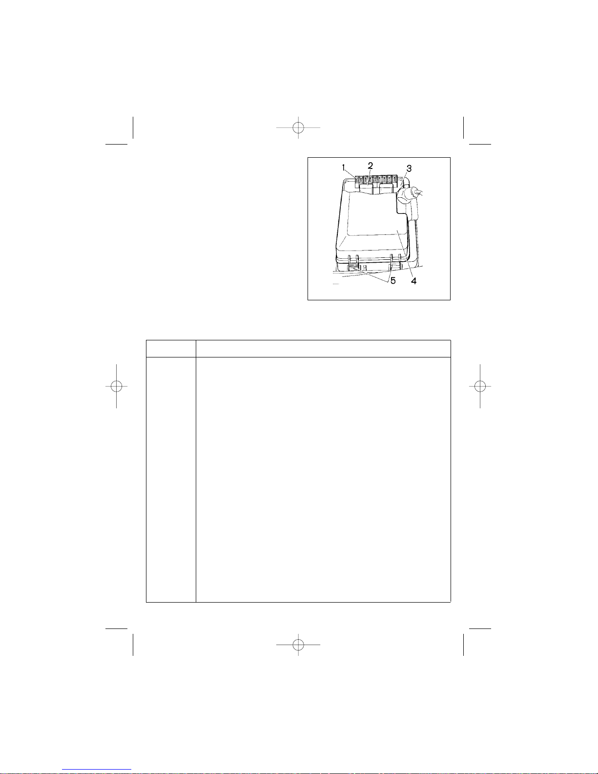
block is located in the air duct in the
vehicle’s left. The fuse/relay block
cover (4) has a legend at the inside
specifying each relay function, fuse
number and protected circuits. The
fuse rating is marked on its face. To
replace a fuse, remove the cover by
depressing locks 5 on both sides, then
pull up the cover. In the event of
repeated fuse blowing, apply to your
dealer to trace and eliminate the cause
of failure.
Circuits protected by fuses are listed
in table 3
Table 3
Circuits protected by fuses
Fuse Protected circuit
F1 (10 A) Headlamp wiper motor (at switch-on).
Headlamp washer motor.
F2 (10 A) Turn-signal lamp.
Turn-signal and hazard flasher relay-interrupter (in hazard warning mode).
F3 (10 A) Interior illumination.
Reading light.
Luggage compartment illumination.
Stoplight.
Lamps relay.
Trip computer.
F4 (20 A) Inspection lamp socket.
Rear window defroster relay (contacts).
Rear window defroster.
F5 (20 A) Horn.
Horn relay.
Radiator fan motor.
F6 (30 A) Power window motors.
Power window activation relay (contacts).
F7 (30 A) Heater motor.
Windscreen washer motor.
Headlamp wiper motor (when activated).
Cigarette lighter.
F8 (7.5 A) Foglamp (R.H.)
F9 (7.5 A) Foglamp (L.H.)
39
Fig. 43. Fuse and relay block
RE2115eng 23/04/2002 15:23 Page 39
Page 40

40
Fuse Protected circuit
F10 (7.5 A) Instrument cluster illumination switch.
Number plate lamps.
Engine compartment illumination.
Illumination for control switches, instrument cluster, cigarette lighter, heater
controls.
Side-markers (L.H.).
Side-markers tell-tale.
F11 (7.5 A) Lamps relay. Side-markers (R.H.).
F12 (7.5 A) Dipped beam (R.H. headlight)
F13 (7.5 A) Dipped beam (L.H. headlight)
F14 (7.5 A) Main beam (L.H. headlight)
F15 (7.5 A) Main beam (R.H. headlight)
F16 (15 A) Instrument cluster.
Turn-signal lamp and hazard flasher relay-interrupter (in turn signal indica-
tion mode).
Low oil pressure tell-tale.
Alternator excitation winding (at engine cranking).
Injection vehicles feature three fuse boxes installed on a bracket behind the instrument panel console. Each fuse is rated for 15A. Circuits protected by these fuses are
listed in table 4.
Table 4
Circuits protected by fuses
Fuse Protected circuit
Upper (15 A) Fuel pump relay (contacts).
Fuel pump.
Injectors.
Middle (15 A) Radiator fan motor activation relay (winding).
Canister purge valve*.
Mass airflow sensor.
Vehicle speed sensor.
Heated oxygen sensor* (heater).
Lower (15 A) ECM.
Ignition module.
Inserted fuses (supplied with the harness)
8 A Rear fog light relay.
Rear fog light.
16 A Seat heater.
16 A Central door lock control.
Central door lock motor.
RE2115eng 23/04/2002 15:23 Page 40
Page 41
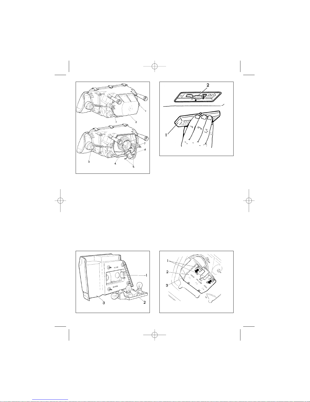
Never use a makeshift jumper or a
fuse with different rating to replace a
blown fuse.
No fusible links are used to protect
the circuits of the following components:
ignition, starter, alternator, headlamp
activation relay and central door locking
relay.
BULB REPLACEMENT
For replacement use the bulbs as
listed in Appendix #2.
To replace headlamp light bulbs,
unscrew bolts 1 and remove cover 2
(Fig. 44). Disengage retaining spring 5
and remove connector 6 with bulb 4.
To replace the side-marker light
bulb, remove bulb holder 7 assembly
from the socket, turn the bulb counterclockwise and pull it out.
To replace a bulb in the front turnsignal lamp, disengage connector 3,
turn the holder counterclockwise and
pull it out.
To replace bulbs in rear lamps 3
(on vehicle body – Fig. 45; on boot
lid/tailgate – Fig. 46), open the boot lid,
41
Fig. 46. Tail lights on the boot lid/
tailgateFig. 45. Tail lights on the body
Fig. 44. Headlamp
Fig. 47. Interior light
RE2115eng 23/04/2002 15:23 Page 41
Page 42
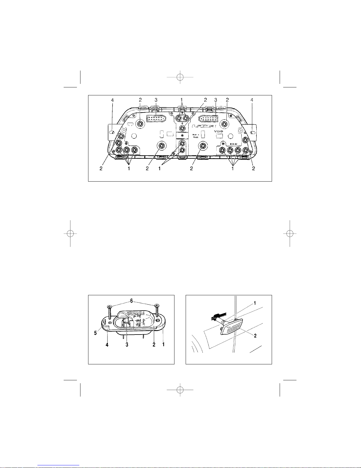
remove the protective covers, prize
latches 1 and remove base 2 with the
lamps attached.
To replace interior light bulb 2
(Fig. 47), first remove lens 1 by pressing the centre part with your fingers and
pulling it down.
To replace tell-tale light bulb 1
(Fig. 48) or instrument cluster illumination bulb 2, carefully remove the instrument cluster cover, undo screws holding the cluster by eyelets 4. Pull out the
instrument cluster and disconnect harness connectors 3 as necessary. Turn
the bulb to be replaced counterclockwise and pull it out of the socket.
To replace number plate lamp
bulb 3 (Fig.49), first remove the lamp.
To do so, undo screws 6, insert a
screwdriver into cutout 4, press latch 5
towards the center with your finger and
carefully withdraw lens 2. Bulb 3 is held
in housing 1 by spring retainers.
To replace a blown bulb in the
side turn-signal lamp (Fig. 50)
remove the latter from the car. The
turn-signal lamp is held in its socket by
spring retainers. Next, remove protective rubber cap 1, withdraw the
bulb/holder assembly from housing 2
and pull the bulb out.
42
Fig. 48. Instrument cluster lamps (rear view)
Fig. 49. Number plate lamp Fig. 50. Side-mounted turn-signal lamp
RE2115eng 23/04/2002 15:23 Page 42
Page 43
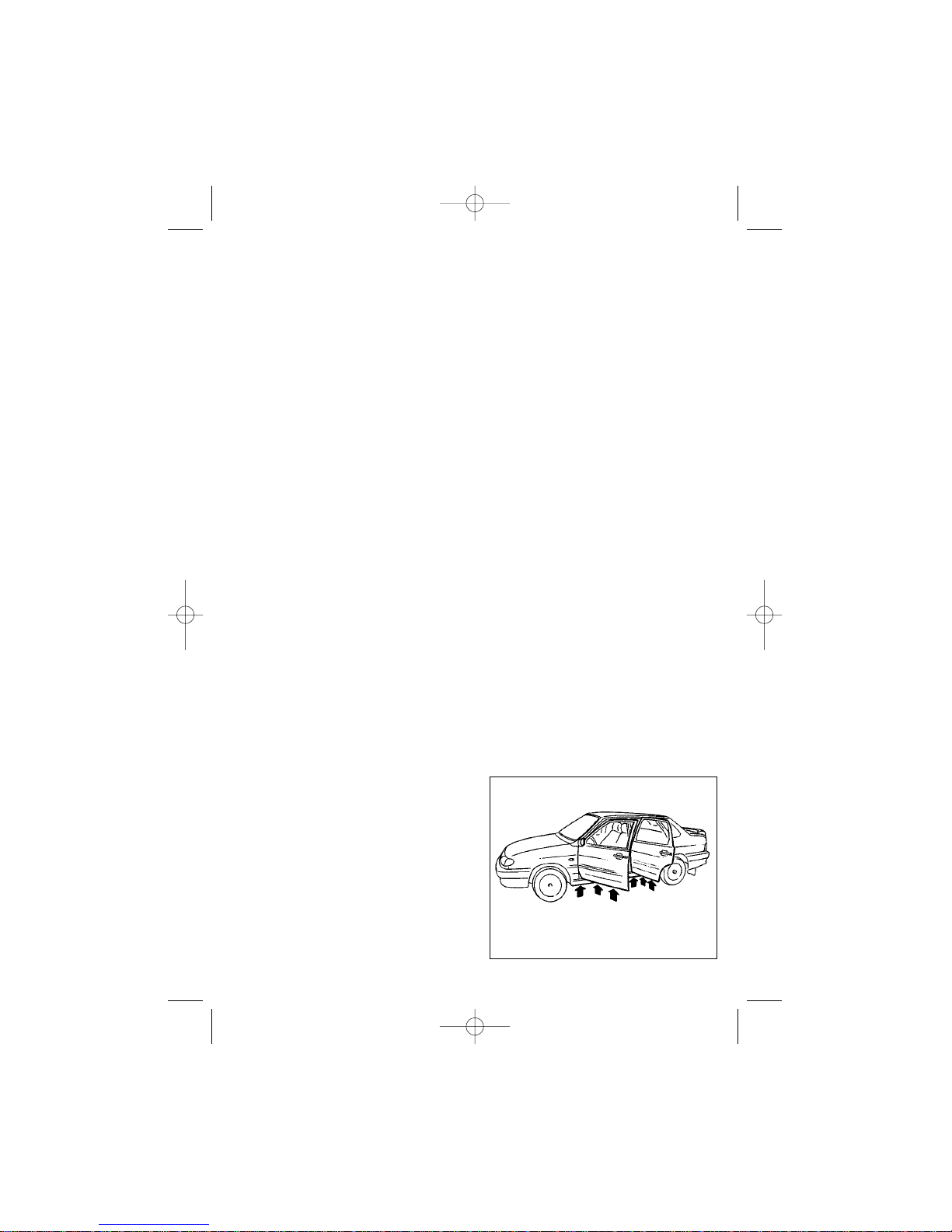
43
BODYWORK
MAINTENANCE
Bodywork is the basic and the most
expensive part of the vehicle. It is manufactured using modern materials and
high quality anticorrosion components.
Corrosion resistance of the body is
basically secured by the manufacturer,
however, much depends on proper
maintenance, particular climatic conditions, environment and storage conditions.
To avoid scratches, do not remove
dust and dirt with a dry rag. It is best to
wash the vehicle immediately after a
trip with a soft sponge using a moderately strong jet of water. On a summer
day wash your vehicle outdoors in a
shady place. If this is impossible, wipe
the paintwork dry immediately after
washing to avoid stains left by water
droplets drying under direct sunshine.
On a winter day wash your vehicle
indoors in a warm place and wipe dry
the paintwork and door weatherstrips
before driving out to avoid possible
negative effects of water droplets freezing: paintwork cracking or weatherstripto-body freezing. Do not use soda,
alkaline solutions or waste waters for
washing, since they may cause dimming of the paintwork.
Before washing your vehicle, clear
out drain holes (Fig. 51) in the doors
and sills. Do not direct water jet on the
electric and electronic components,
sensors, or connectors in the engine
compartment. Inspect the condition of
electronic components and sensors’
connector boots. In case of water coming inside the connector dry it with pressurized air and apply water repellant
substance to prevent oxidation of terminals.
Carefully wash doors’ and bonnet’s
flanged joints, engine compartment
and door apertures welded joints to
avoid accumulation of dirt, which may
damage paintwork and cause corrosion.
In case of visible signs of corrosion
(corroded spots, blistering of paint,
etc.) abrade the affected spot with a
fine grade sandpaper to reveal uncorroded metal, then apply rust converter,
prime and paint the spot.
Spalling and scratching of the paint
finish, spalling of the sealer in the
wheel arches and the underbody may
be caused by mechanical actions during vehicle operation. Corrosion of
welded joints or other bodywork joints
is not penetration corrosion, and for
that reason at early stages it can be
corrected by polishing. Timely correct
corrosion of the paint finish, which may
appear during operation, to prevent further corrosion under the topcoat, its
lamination and blistering.
In order to enhance corrosion resistance of the body, the closed internal
spaces of the door sills, side- and
crossmembers are protected with a
Fig. 51. Door and sill drain holes
RE2115eng 23/04/2002 15:23 Page 43
Page 44

44
special anticorrosion compound. It is
recommended to restore the protective
coating of the closed spaces at your
dealer’s during the first year of vehicle
operation and later every 1.5-2 years.
Exposure of the vehicle underbody
to gravel, sand, salt, etc. affects the
sealers and the prime coat, facilitating
body rusting. Carefully monitor condition of the underbody and correct the
revealed defects in due time and order.
To preserve the shine of the paintwork (especially for outdoor parking)
polish your vehicle on a regular basis
using special creams. Polishing
creams seal new microcracks of the
paintwork and prevent metal corrosion
underneath.
Never leave the vehicle under direct
sunshine for a prolonged period or spill
acids, soda solutions, braking liquid or
petroleum on the bodywork to avoid
dimming of the paint.
Use a clean cloth to wipe off petroleum spillage after filling up — this will
help to prevent staining of the body
under the fuel filler flap.
Use a wet cloth to wipe plastic parts.
Do not use petroleum or solvents, for
they may cause dimming of the plastics.
Remove dust from the seat cushion/
seatback by vacuuming. To remove
greasy spots from upholstery, use universal interior cleaners or neutral soapy
water. Do not forget to thoroughly clean
rubber seals and adjacent door and
boot lid surfaces with a wet cloth.
Clean the glasses with soft linen
rags or chamois leather. Add glasscleaners to water when washing very
dirty glasses (30cm
3
/l).
Due to unfavourable environmental
situation in some regions the paintwork
of the vehicle may be negatively affected. This may appear as rusty dust,
local discolouration or destruction of
the paintwork.
Rusty dust on the bodywork is the
result of airborne metal particles deposition. These particles are later
attached to the body through the
process of corrosion in dew water. To
remove rusty deposits use a 5% solution of oxalic acid and then wash the
vehicle with profuse clean water.
Complete the operation by polishing
the vehicle body. If no special action is
taken to remove the rusty deposits,
they will gradually go away after a number of washes or rains.
Local discolouration (staining) of the
paint finish or destruction of the
clearcoat are caused by deposition of
airborne industrial acids which undergo
chemical transformations in humid air.
Depending on how badly the bodywork
is affected you may have to polish or
repaint the body.
STORAGE
Pay special attention to vehicle storage conditions. If the vehicle runs
15000 kilometers a year, it means that
it is only 1 hour in operation out of 24.
Optimum conditions for vehicle storage
are:
— a shed with the temperature and
humidity at the same level as the ambient, constant airflow and no sun or
weather exposure.
— warm (single lot) garage with the
temperature at least 5°C, relative
humidity 50-70% and combined supply/exhaust ventilation system.
If the ventilation system of the warm
(single lot) garage is inefficient, and the
RE2115eng 23/04/2002 15:23 Page 44
Page 45

45
vehicle is operated during winter or is
left for storage without drying after a
wash, the destructive effect on the
paint finish will multiply.
If you are planning to leave the vehicle for a long period under a shed or in
a cold garage during winter, disconnect
the battery and the car radio and take
them away for separate safekeeping;
also drain the washer fluid.
For indoors keeping with the sunlight coming in cover the vehicle body
and tyres with a permeable canvas.
Use of watertight covers (e.g. tarpaulin,
polyethylene, etc.) without holes for
windscreen and rear window ventilation
results in water condensation and
eventually damages the paint finish.
For outdoors keeping when a canvas is used do not allow it to touch
painted parts of the vehicle body to prevent paint damage (blistering, spalling,
etc.). Place soft pads at least 20 mm
thick between the vehicle body and the
canvas to allow proper ventilation.
To prepare the vehicle for a long
storage:
1. Wash the vehicle and wipe it dry.
Remove corrosion, repaint spalling
spots and coat the body with a preservative compound.
2. Start the engine and allow it to
warm up. Stop the engine, remove the
spark plugs and fill each cylinder with
25-30 g of motor oil heated to 70-80°C,
then make 10-15 crankshaft rotations
and replace the sparkplugs.
3. Disconnect the warm air intake
pipe from the air cleaner. Use oilpaper
or oilcloth to close:
— air cleaner intake openings;
— muffler tailpiece;
4. Cover the engine with tarpaulin,
polyethylene or oilpaper.
5. Place the vehicle on supports so
that the wheels do not touch the
ground.
6. Cover the vehicle with a canvas.
7. Fully charge the storage battery
and take it away for storage in a dry
and moderately cool place.
Service the vehicle once every two
months of storage as follows:
1. Remove the cover and visually
inspect the vehicle. Abrade and repaint
corroded spots.
2. Remove the sparkplugs, shift into
the 5th gear, rotate the front wheel 2-3
times and replace the spark plugs.
3. Rotate the steering wheel 1-1.5
turns in each direction. Depress (3-5
times) the brake, the clutch and the
accelerator pedals, and apply (3-5
times) the handbrake.
RE2115eng 23/04/2002 15:23 Page 45
Page 46
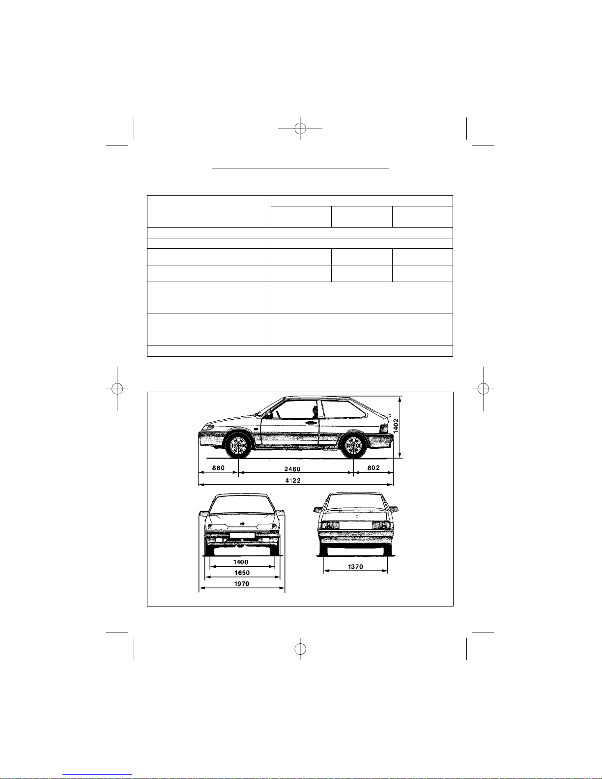
46
MAIN PERFORMANCE PARAMETERS AND DIMENSIONS
_____________
* Optional for injection engine vehicles.
** Vertical load on the drawbar hook at rest should be within 25-50 kg.
TECHNICAL SPECIFICATION
VAZ 2113 VAZ 2114 VAZ 2115
Body type 3-door hatchback 5-door hatchback 4-door saloon
Power system
Number of seats, occupants
Kerbweight, kg 920 945
2115-01—970
2115-20—985
Gross Vehicle Weight (GVW), kg 1345 1370
2115-01—1395
2115-20—1410
Ground clearance at GVW, at least, mm:
— to oil sump
— to catalytic converter*
Trailer Gross Weight**, kg
— unbraked
— braked
Overall dimensions, mm
Parameters
Fig. 52-54
Models (including modifications)
Front-wheel drive with transversely mounted engine
5
165
130
300
750
Fig. 52. Vehicle VAZ 2113 (and modifications) overall dimensions
RE2115eng 23/04/2002 15:23 Page 46
Page 47
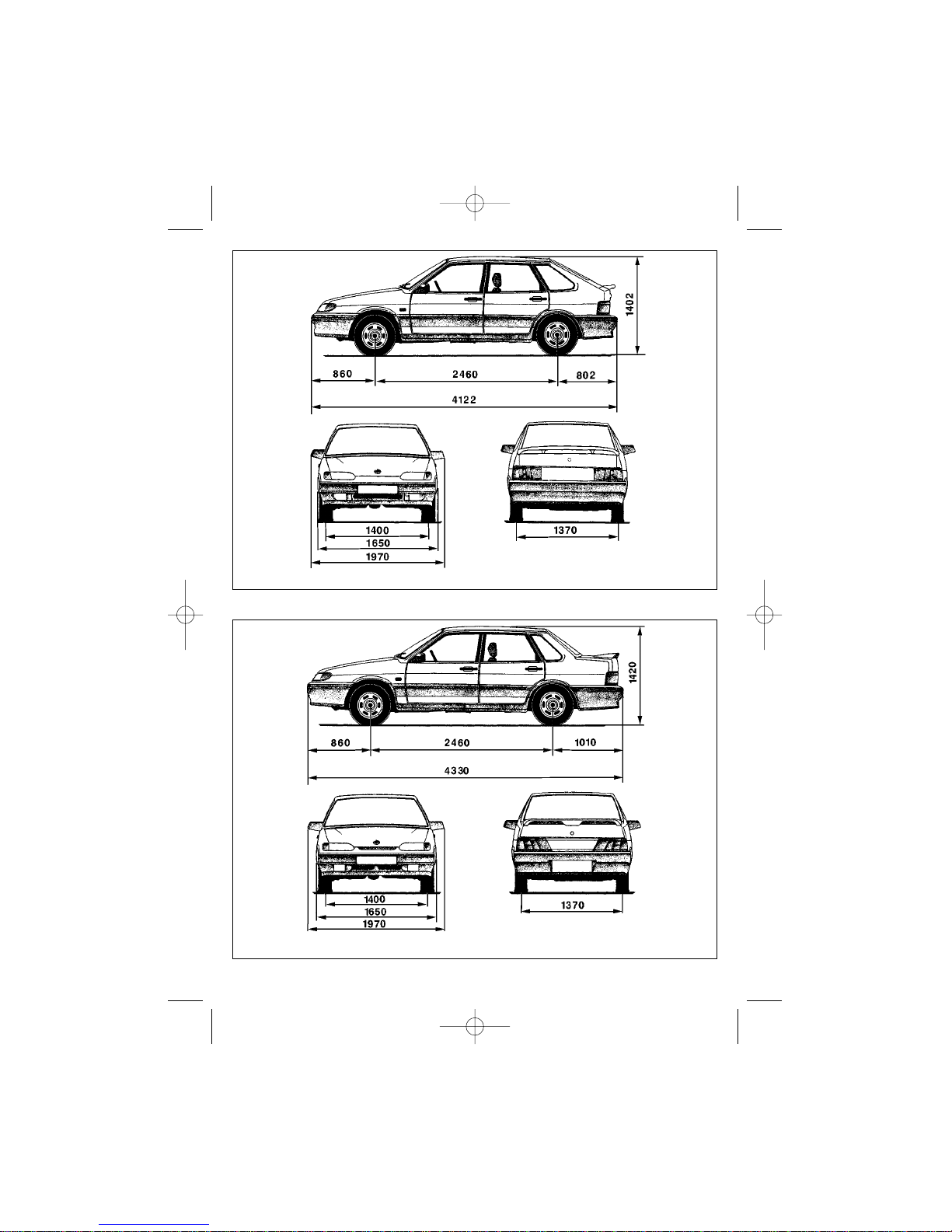
47
Fig. 54. Vehicle VAZ 2115 (and modifications) overall dimensions
Fig. 53. Vehicle VAZ 2114 (and modifications) overall dimensions
RE2115eng 23/04/2002 15:23 Page 47
Page 48
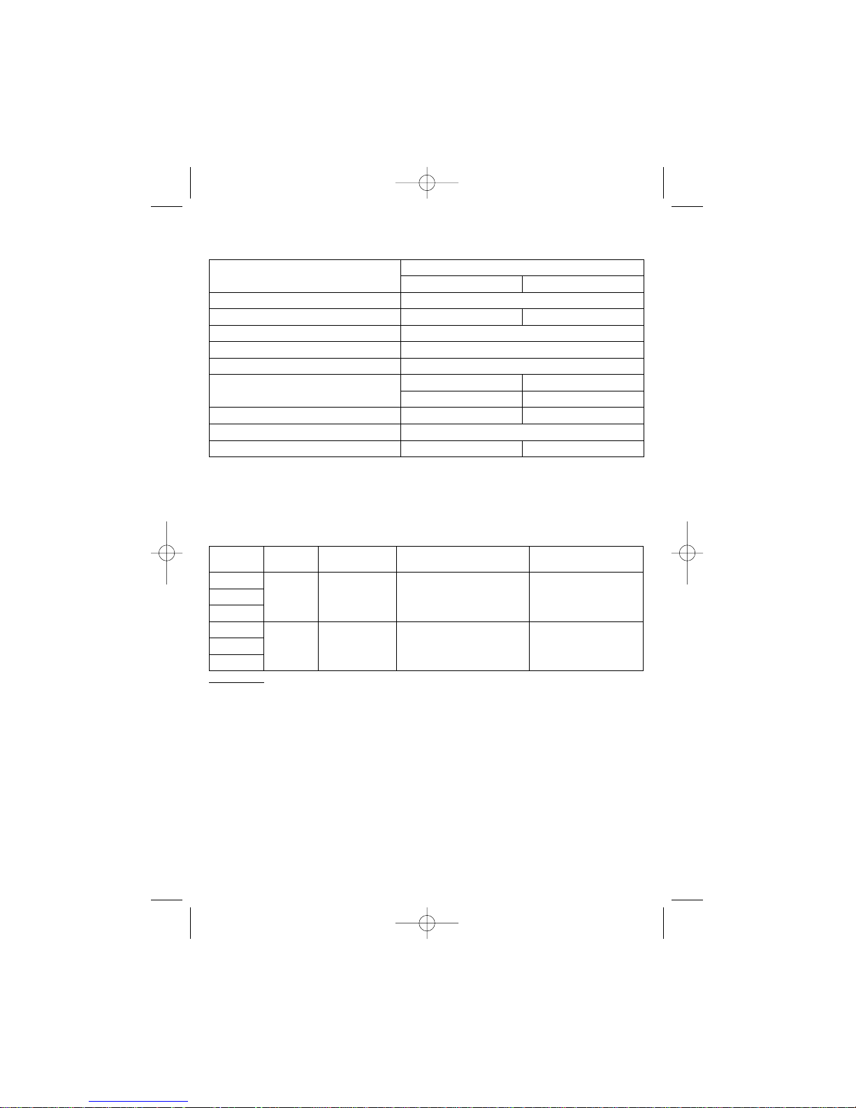
48
ENGINE PARAMETERS
VEHICLE SPECIFICATIONS
CAPACITIES
(litres)
Fuel tank. . . . . . . . . . . . . . . . . . . . . . . . . . . . . . . . . . . . . . . . . . . . . . . . . . . . . . . . . . . . 42.5
Engine cooling system, including heater . . . . . . . . . . . . . . . . . . . . . . . . . . . . . . . . . . . . . 7.8
Engine lubrication system . . . . . . . . . . . . . . . . . . . . . . . . . . . . . . . . . . . . . . . . . . . . . . . . 3.5
Gearbox housing. . . . . . . . . . . . . . . . . . . . . . . . . . . . . . . . . . . . . . . . . . . . . . . . . . . . . . . 3.3
Brake hydraulic system . . . . . . . . . . . . . . . . . . . . . . . . . . . . . . . . . . . . . . . . . . . . . . . . 0.435
Windscreen washer fluid tank . . . . . . . . . . . . . . . . . . . . . . . . . . . . . . . . . . . . . . . . . . . . . 4.2
21083 2111
Engine type
Fuel delivery system carburettor/ breakerless ign. multipoint fuel injection
Capacity, L
Bore x Stroke, mm
Compression ratio
Rated power**, kWatt (h.p.) 51.5 (70) 57.2 (78)
at RPM 5600 5400
Minimum engine speed, RPM 750-800 760-840
Spark plugs
Fuel 91 RON unleaded fuel (95 RON)
Parameters
А17ДВРМ
1.5
82x71
Engine
4-cylinder, in-line, 4-stroke
9.8
Vehicle Engine
Max. speed*,
km/h
Acceleration*
from 0 to 100 km/h, sec
Fuel Consumption**,
l/100 km
2113
2114
2115
2113
2114
2115
* Measured using special procedure.
** Figures reflect fuel consumption in L/100 km at: 90 km/h / 120 km/h / urban driving.
2111
21083
5.7 / 7.8 / 8.9
5.7 / 7.8 / 8.9
155
155
14.2
14.2
RE2115eng 23/04/2002 15:23 Page 48
Page 49

49
ADJUSTMENT AND CONTROL PARAMETERS
Valve train clearances on a cold engine (18-20°C):
— intake valves . . . . . . . . . . . . . . . . . . . . . . . . . . . . . . . . . . . . . . . . . . . . . . . . . . . .0.2±0.05
— exhaust valves . . . . . . . . . . . . . . . . . . . . . . . . . . . . . . . . . . . . . . . . . . . . . . . . .0.35±0.05
Spark gap, mm:
— carburetor engine . . . . . . . . . . . . . . . . . . . . . . . . . . . . . . . . . . . . . . . . . . . . . . . . . .0.7-0.8
— fuel injection engine . . . . . . . . . . . . . . . . . . . . . . . . . . . . . . . . . . . . . . . . . . . . . .1.00-1,13
Steering wheel free travel in the position for straightforward driving, ≤ ° . . . . . . . . . . . . . . . .5
Brake pedal free travel with the engine stopped, mm . . . . . . . . . . . . . . . . . . . . . . . . . . . .3-5
Clutch pedal travel, mm:
— when adjusting . . . . . . . . . . . . . . . . . . . . . . . . . . . . . . . . . . . . . . . . . . . . . . . . . . .125-135
— operating . . . . . . . . . . . . . . . . . . . . . . . . . . . . . . . . . . . . . . . . . . . . . . . . . . . . . . .150-160
Minimum safe front/rear brake lining thickness, mm . . . . . . . . . . . . . . . . . . . . . . . . . . . . .1.5
Coolant temperature on a warmed up engine, ambient temperature 20-30°C,
at full load and at 80 km/h, ≤ °C . . . . . . . . . . . . . . . . . . . . . . . . . . . . . . . . . . . . . . . . . . . .95
Maximum permissible oil consumption during the warranty period, ≤ L/100km . . . . . . . . .0.3
Alternator driving belt sag at 100N (10kgf), mm . . . . . . . . . . . . . . . . . . . . . . . . . . . . . .10-15
Parking brake lever travel, cogs:
— when adjusting . . . . . . . . . . . . . . . . . . . . . . . . . . . . . . . . . . . . . . . . . . . . . . . . . . . . . .2-4
— operating . . . . . . . . . . . . . . . . . . . . . . . . . . . . . . . . . . . . . . . . . . . . . . . . . . . . . . . . . . .2-8
Storage battery electrolyte density (6CT-55) at 25°C in moderate climate, g/cm
3
. . . . . . .1.28
Coolant level in the expansion tank on a cold engine . . . . . . . .25-30 mm over the MIN mark
Braking fluid level with new brake linings and the brake
fluid reservoir cap removed . . . . . . . . . . . . . . . . . . . . . . . . . . . . . . . . . . . . .to the MAX mark
Oil level in the gearbox . . . . . . . . . . . . . . . . . . . . . . . . . . . . . . . . . . .between the two marks
Front wheels toe-in on a vehicle loaded with 3200N (320kgf), mm . . . . . . . . . . . . . . . . . .0±1
Front wheels camber on a vehicle loaded with 3200N (320kgf), ° . . . . . . . . . . . . . . . . .0°±30'
Front wheels camber on a vehicle loaded with 3200N (320kgf),
measured between the wheel rim and the vertical line, mm . . . . . . . . . . . . . . . . . . . . . . .0±3
Caster on a vehicle loaded with 3200N (320kgf), ° . . . . . . . . . . . . . . . . . . . . . . . . .1°30'±30'
RE2115eng 23/04/2002 15:23 Page 49
Page 50
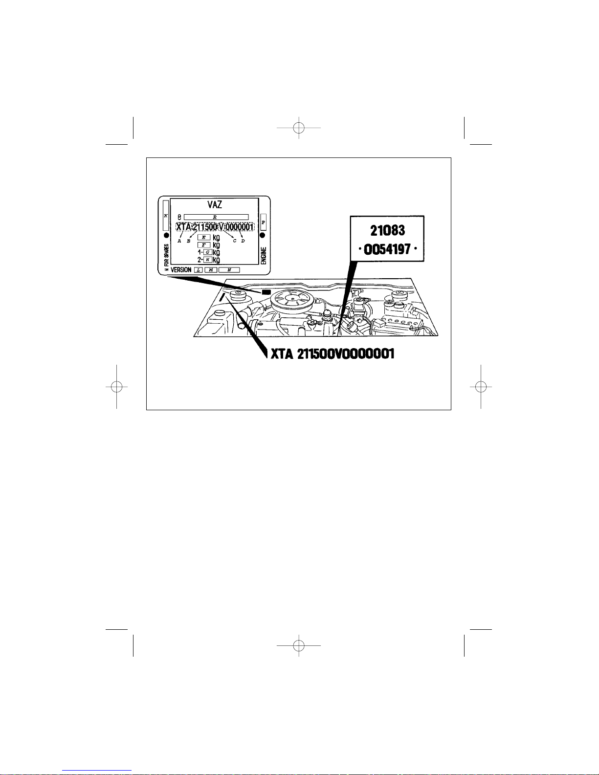
50
VEHICLE IDENTIFICATION
DATA
Vehicle identification plate (Fig.55)
contains the following information:
Vehicle identification number
(VIN):
A
— manufacturer’s code;
B
— vehicle model;
C
— model year;
D
— chassis number (for passenger
cars also the body number).
Additional Information:
E
— gross vehicle weight;
F
— gross vehicle and trailer weight;
G
— permissible load on front axle;
H
— permissible load on rear axle;
K
— spare parts number. Corresponds to sequential production number;
L
— emissions letter code (optional-
ly);
M
— version code (2 digits);
N
— package (specification) code (3
digits);
P
— engine model;
R
— number of EEC vehicle typeapproval certificate.
Engine model and number are
stamped on the cylinder block face
above the clutch bell housing.
VIN is also stamped on the righthand telescopic strut and on the boot
flooring in the spare wheel well.
Fig. 55 Vehicle identification data
RE2115eng 23/04/2002 15:23 Page 50
Page 51

51
APPENDICES
Appendix #1
FUELS, LUBRICANTS AND FLUIDS
Place Description
Fuel tank Unleaded petrol with at least 95 RON
Lubrication system Engine oils:
SAE: 5W-30: from –25 to +20 °C
5W-40: from –25 to +35 °C
10W-30: from –20 to +30 °C
10W-40: from –20 to +35 °C
15W-40: from –15 to +45 °C
20W-40: from –10 to +45 °C
API: SG, SJ, SH
ACEA: A2/B2
CCMC: G3 or G4
Recommended oils: ESSO ULTRA
ESSO UNIFLO
SHELL HELUX SUPER
LUKOIL
Gearbox Transmission oils
SAE: 80W-85, 85W-90
API: GL-4
Engine cooling system Ethylene glycol based antifreeze with
corrosion inhibitors and foam suppresant
Recommended: SPECTROL ANTI-FREEZE
AGIP ANTIFREEZE EXTRA
Glysantin G 03 (BASF)
Brake and clutch release Brake fluids of DOT-4 type,
hydraulic systems to meet SAE J1703f or FMVSS116A
Recommended: SPECTROL DISK BRAKE
FLUID DOT-4 (POCA)
AGIP BRAKE FLUID DOT-4
HYDRAULAN 408 (BASF)
Washer fluid tanks Any alcohol-based glass cleaner
RE2115eng 23/04/2002 15:23 Page 51
Page 52

52
Appendix #2
ELECTRIC BULBS USED IN THE VEHICLE
Lamp Type
Headlamps:
– dipped and main beam AKГ12–60/55 (H4 12V 60/55W)
– turn-signal lamp A12–21–3 (P 12V 21W)
– side-marker A12–4–1 (T 12V 4W)
Front foglight AKГ12-55-1 H3 12V 55W
Tail lights:
– turn-signal lamp A12–21–3 (P 12V 21W)
– stop-light and side-marker A12–21+5 (P 12V 21+5W)
Tail lights on the tailgate:
– reversing light A12–21–3 (P 12V 21W)
– foglight A12–21–3 (P 12V 21W)
Add. stop-light A12–5–2 (W 12V 5W)
Side-mounted turn-signal lamps A12–5–2 (W 12V 5W)
Number plate illumination AC12–5 (C 12V 5W)
Interior light AC12–5–1 (C 12V 5W)
Reading light A12–4–1 (T 12V 4W)
Inspection lamp A12-5-1 (P 12V 5W)
Underbonnet lamp A12-5 (P 12V 5W)
Boot illumination AC12–5–1 (C 12V 5W)
Cigarette lighter illumination A12–4 (T 12V 4W)
Glovebox illumination AC12–5 (C 12V 5W)
Ashtray illumination AH12–1,2 (12V 1.2W)
Instrument cluster illumination AH12–1,2 (12V 1.2W)
Instrument cluster tell-tales AH12–1,2 (12V 1.2W)
Illumination and indication for control switches CMH12–46 (12V 0.46W)
Illumination and indication for exterior light
control switch ACMH12–0.55 (12V 0.55W)
Автомобили ВАЗ 2113, ВАЗ 2114, ВАЗ 2115
Руководство по эксплуатации на английском языке
ДТР АО «АВТОВАЗ»
Составители: Казаков Н. В., Косарев С. Н.
Перевод с русского: А. Выборнов
2002 год. Изд. № 021511
Отпечатано офсетным способом в типографии ДИС АО «АВТОВАЗ» с готового макета-
оригинала
Зак.
RE2115eng 23/04/2002 15:23 Page 52
 Loading...