

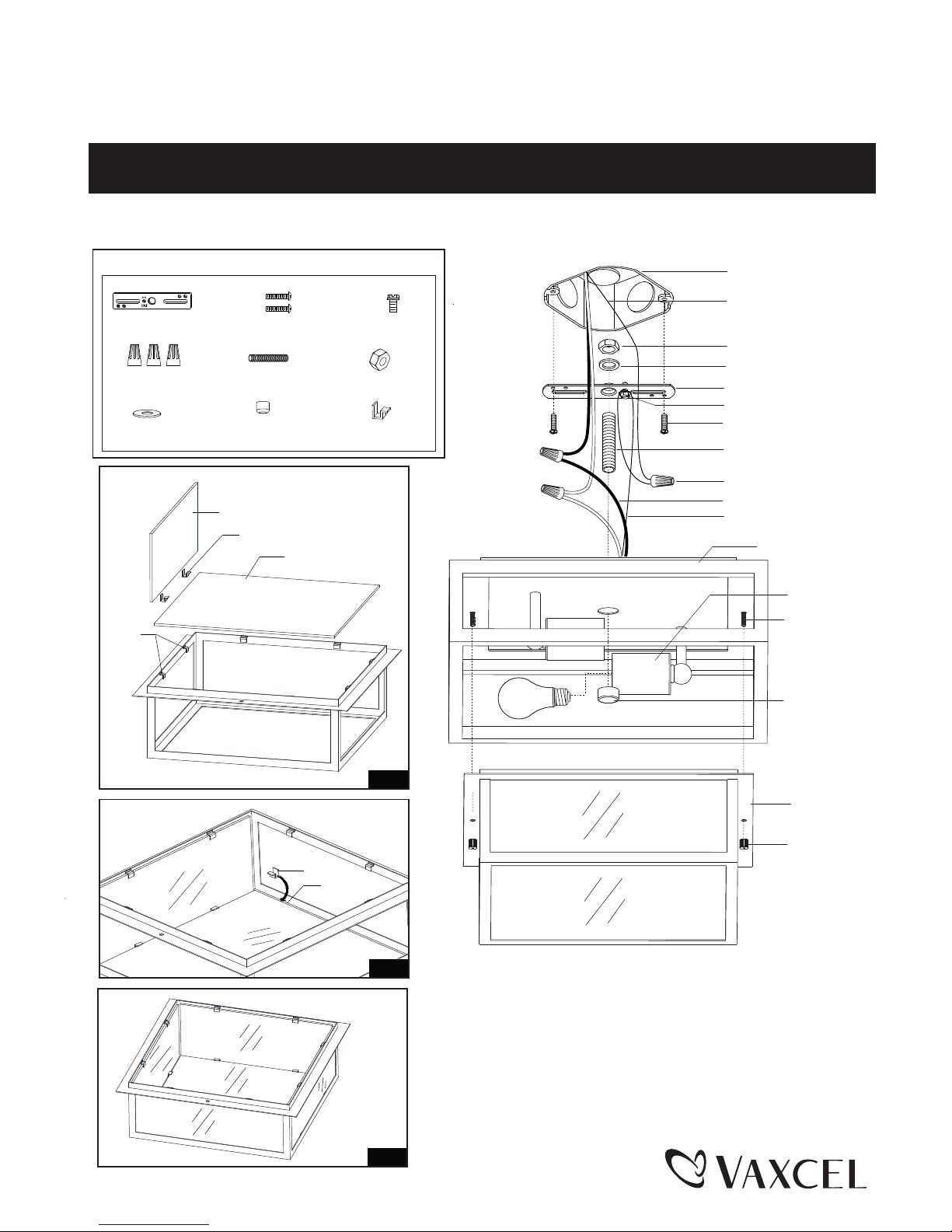
Fig.1
Fig.3
Fig.2
ASSEMBLY AND INSTALLATION
INSTRUCTIONS
NOTES: 1. Before installing, consult local electrical codes for wiring and grounding requirements.
2. READ AND SAVE THESE INSTRUCTIONS.
T0241
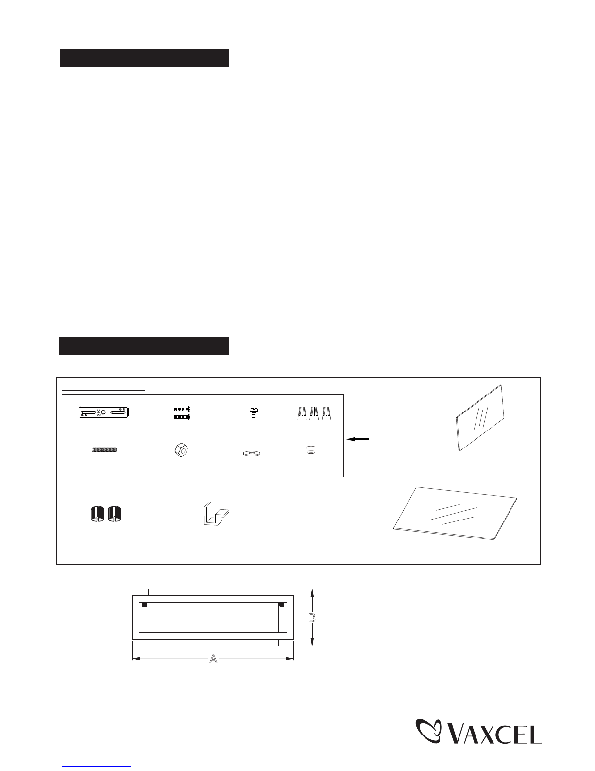
Hardware Package (included):
WARNING:
TO AVOID RISK OF ELECTRICAL SHOCK, BE SURE TO SHUT OFF
POWER BEFORE INSTALLING OR SERVICING THIS FIXTURE.
160304
Mounting Screw (B)
Green Grounding Screw (C)
Wire Nut (D)
House Grounding Wire
Fixture Grounding Wire
Outlet Box
Fixture Wire
Threaded Pipe(E)
Mounting Strap (A)
Hex Nut (F)
Washer (G)
Ceiling Pan
End Cap(H)
Metal Frame
Bolt Nut
Small Threaded
Pipe
Socket
Mounting Screw (B)
Threaded Pipe (E)
Green Grounding
Screw (C)
Wire Nut (D)
Mounting Strap (A)
Hex Nut (F)
Washer(G)
End Cap(H)
Bulb Type A Max.60W
(not included)
Side Glass Panel
Bottom Glass Panel
Top Clip
Slot
“S” Clip (I)
“S” Clip (I)
“S” Clip (I)
(9PCS)
A
B
160304
Mounting Screw (B)
Threaded Pipe (E)
Green Grounding
Screw (C)
Wire Nut (D)
Mounting Strap (A)
Hex Nut (F)
Washer(G)
End Cap(H)
Bolt Nut
5540BB (2PCS)
Turn off the power at fuse or circuit box.
Turn on the power at fuse or circuit box.
Installation Steps
1. Attach the threaded pipe to the mounting strap, and then secure it with a washer and a hex nut.
2. Attach mounting strap to outlet box using two mounting screws.
3. Remove two bolt nuts to separate the metal frame from ceiling pan.
4. Pull out the source wires from the outlet box. Make wire connections using wire nuts as follows:
---Connect the hot wire (usually black insulation) from the power source to the black wire from the fixture.
---Connect the neutral wire (usually white insulation) from the power source to the white wire from the fixture.
---Attach the fixture grounding wire (usually green insulation or bare wire) to the mounting strap with the green
grounding screw, or connect to the source grounding wire if available.
Carefully put the wires back into the outlet box.
5. Attach the ceiling pan to the mounting strap by inserting threaded pipe into the center hole of the ceiling pan, and
then screw the end cap to secure ceiling pan.
6. Install two bulbs (not included). Check relamping label at socket area or packaging for maximum allowed wattage.
7. Place the bottom glass panel into the metal frame, and then set eight "S"clips on the slot and fix the bottom glass
panel by inserting the side glass panels onto the “S”clips, finally press the top clips of the metal frame to secure
the side glass panels. (See Fig 1. / Fig 2. / Fig 3.)
8. Attach the metal frame back to ceiling by inserting small threaded pipes into holes on metal frame, and then secure
it with two bolt nuts.
“S” Clip (I)
1074CP (9PCS)
The following parts are available for re-order if damaged or missing.
Spare Parts List:
Assembly Kit
5539MM (1 SET)
Bottom Glass Panel
9807RG (1 PC)
Side Glass Panel
9808RG (4 PCS)
A: 12" B: 4-1/2"
 Loading...