

Page 1
ASSEMBLY AND INSTALLATION
INSTRUCTIONS
T0213 / T0214
TO AVOID RISK OF ELECTRICAL SHOCK, BE SURE TO SHUT OFF
WARNING:
NOTES: 1. Before installing, consult local electrical codes for wiring and grounding requirements.
2. Read and save these instructions.
POWER BEFORE INSTALLING OR SERVICING THIS FIXTURE.
Important to Know
1. Read all instructions carefully before installation and
operation.
2. If you are not familiar with state and local electrical codes,
it is recommended that you consult with a qualified
electrician.
3. Before installation, shut off power at the main fuse or
circuit breaker box. Be aware that simply turning off the
wall switch is not sufficient to prevent an electrical shock.
4. This fixture requires a 120V AC, 60 Hz power source.
5. Do not attempt to take the lantern apart; there are no
serviceable parts inside.
6. To avoid sensor damage by lightning or electrical surge,
make sure the grounding wire is securely connected.
7. For general safety and to avoid any possible damage to
the sensor, be sure the power is switched "off" before
replacing the bulb.
Maximum Wattage: 60W
Work Temperature: -4ºF ~ 104ºF
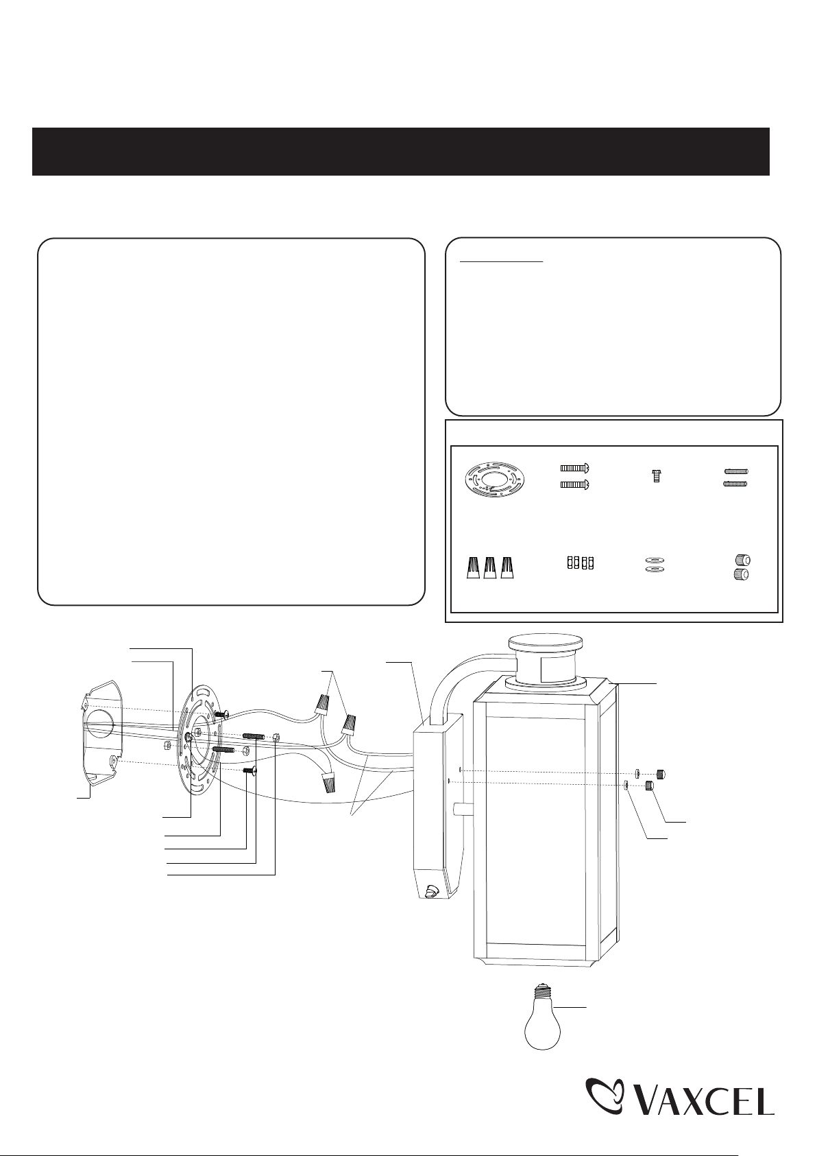
Mounting Plate (A)
House Grounding Wire
Wire Nut (E)
Back plate
Features
1. Energy saving fixture.
2. Use the dim-to-bright illumination option where
you want some minimum illumination through out
the night, such as at your front entrance or
garage door. Use the dark-to-bright illumination
option where you do not need minimum
brightness, such as the backyard or back porch.
3. When in manual override mode, use wall switch
to keep the light ON till dawn.
Hardware Package (included):
Mounting Plate (A)
Wire Nut (E)
Mounting
Screw (B)
Lock Nut (F)
Green Grounding
Screw (C)
Rubber Pad (G)
Fixture
Headless
Screw (D)
Ball Nut (H)
Outlet Box
Green Grounding Screw (C)
Fixture Grounding Wire
Mounting Screw (B)
Headless Screw (D)
Lock Nut (F)
Fixture Wire
Page 1 / 4
Ball Nut (H)
Rubber Pad (G)
Max Watt: 60W (M) - Type A
Incandescent, Halogen or
Dimmable LED
(not include)
151022
Page 2

Installation Steps
Turn off the power at fuse or circuit box.
1. Thread two headless screws through the mounting plate, and then secure them with four lock nuts (two on each
side of the mounting plate). Adjust the length of the headless screws if necessary.
Note: Make sure that the headless screws are lined up horizontally to make the fixture level.
2. Attach mounting plate to the outlet box using two mounting screws.
3. Pull out the wires and grounding wire from the outlet box. Make wire connections using the wire nuts as follows:
---Connect the hot wire (usually black insulation) from the fixture to the black wire from the power source.
---Connect the neutral wire (usually white insulation) from the fixture to the white wire from the power source.
---Attach the fixture grounding wire (usually green insulation or bare wire) to the mounting plate with the green
grounding screw, and then connect it to the house grounding wire with the wire nut.
Carefully put the wires back into the outlet box.
4. Attach the back plate to the mounting plate by inserting the headless screws, and then secure it with two rubber
pads and two ball nuts.
NOTE: With silicone caulking compound, caulk completely around where the back plate meets with the
wall surface to prevent water from seeping into the outlet box.
5. Install a bulb (not included). Check relamping label at socket area or packaging for maximum allowed wattage.
Turn on the power at fuse or circuit box.
Function and Operation
MODES OF OPERATION
Choose a mode by sliding the switch on the bottom of the back plate of the fixture. (See Fig.2 ).
When power is first applied, the light will turn to high level brightness, wait for 15 seconds to allow the sensor to warm up.
1. TEST MODE (daytime and nighttime operation)
● The light will turn to low-level brightness (0%~50% brightness). The light will turn to high-level brightness (100%
brightness) when motion is detected, and stay on as long as the motion is continuing. The light will revert to
low-level brightness about 5 seconds after motion is no longer detected.
2. 3H MODE (nighttime operation only)
●At dusk, the light will turn to high-level brightness (100% brightness). The light will turn to low-level brightness (0%
~50% brightness) automatically after 3 hours. The light will turn to high-level brightness (100% brightness) when
motion is detected, and stay on as long as the motion is continuing. When motion is no longer detected, the light
will remain on for the predetermined time you set (5~180 seconds), and then revert to low-level brightness you set.
● Light will turn off automatically at dawn, and return to 3 H mode at dusk.
3. 6H MODE (nighttime operation only)
●At dusk, the light will turn to high-level brightness (100% brightness). The light will turn to low-level brightness (0%
~50% brightness) automatically after 6 hours. The light will turn to high-level brightness (100% brightness) when
motion is detected, and stay on as long as the motion is continuing. When motion is no longer detected, the light
will remain on for the predetermined time you set (5~180 seconds), and then revert to low-level brightness you set
● Light will turn off automatically at dawn, and return to 6 H mode at dusk.
4. 0 MODE (nighttime operation only)
● The light will turn to low level brightness (0%~50% brightness) at dusk. The light will turn to high-level brightness
(100% brightness) when motion is detected, and stay on as long as the motion is continuing. When motion is no
longer detected, the light will remain on for the predetermined time you set (5~180 seconds), and then revert to
low level brightness you set.
● Light will turn off automatically at dawn, and return to 0 H mode at dusk.
Page 2 / 4
151022
Page 3

5.Manual Override MODE (nighttime operation only; on at dusk,off at dawn)
● In 3, 6 or 0 mode, to shift to manual override mode, turn off the wall switch in 3 seconds and then turn it on again,
the light will turn to high-level brightness at dusk, and turn off automatically at dawn. To return to the previous
settings, turn off the wall switch in 3 seconds and then turn it on again. (See Fig.1)
● The lights will turn off automatically at dawn.
Note:You can adjust the low level brightness (0~50%) by using the slide switch on the side of back plate.
(See Fig.2)
Fig.1
“3H Mode”
“6H Mode”
“0 Mode”
Manual Override Operation Diagram
Turn wall switch OFF-ON
in 3 Seconds
Turn wall switch OFF-ON
in 3 Seconds again
Manual
Override
Mode
Fig.2
(View from one side of Back plate)
(Adjustable low level)
CUSTOMIZATION OPTIONS:
Shut-off Delay
Fig.3
(View from Bottom of Back plate)
The Shut-off delay is the length of time the light will stay at highlevel brightness after motion has ceased to be detected. This
Shut-off delay can be set when operation is in 3, 6 or 0 Mode by
using the “TIME” knob located on the left side of the panel at the
bottom of the back plate (See Fig.3) . To increase the shut-off
TIME
SENSITIVITY
TEST03 6
(Exterior Wall)
delay, turn the knob clockwise. To decrease shut off delay, turn
the knob counterclockwise. The delay may be adjusted from a minimum of 5 seconds to a maximum of 3 minutes. The
light will stay on as long as motion is detected continuously and will automatically turn to low-level brightness when no
more motion is detected after the delay time has passed.
Sensitivity of Motion Sensor
The sensitivity of the motion sensor can be adjusted by using the “SENSITIVITY” knob located on the right side of the
panel at the bottom of the back plate (See Fig.3). To increase sensitivity, turn the knob clockwise. To decrease
sensitivity, turn the knob counterclockwise. The sensitivity may be adjusted from a minimum of 5 feet to a maximum of
40 feet.
NOTE:
1. The sensitivity of the motion sensor will increase as the
environmental temperature gets cooler. For best
performance, gently clean the lens with a soft cloth every
1 or 2 months to assure maximum sensitivity.
2. For best performance, install fixture at least 6 feet above
the ground. At such a height, the fixture will provide a
detection distance of up to 40 feet at 77 degrees
Fahrenheit. (See Fig.4)
Where you install your lantern is important:
Be sure the light is mounted straight on the wall;
otherwise, the detection distance may be limited.
10`
6`
Fig.4
5`
40`
220'
Fig.5
3. The sensor detects across a detection range of 220 degrees.
(See Fig.5)
4. The sensor will be more sensitive to motion across its
detection path than motion directly towards it. (See Fig.6)
5. To reduce possible nuisances, do not mount the fixture
near a heat source like an air conditioner, vent or furnace
exhaust, or in a direction facing any reflecting object or
other light source.
Page 3 / 4
Fig.6
Motion
Least sensitive
Motion
Sensor
Most sensitive
151022
Page 4

Troubleshooting
---If the light does not work at all:
1. Make sure the wall switch and circuit breaker are on.
2. Make sure the wiring connection is correct.
3. Make sure the bulb is not burned out.
4. Cover the sensor with your palm to verify that the ambient light level is not too high.
----In Test Mode, if the light stays on full brightness after 5 seconds:
1. Check whether the motion is detected at all time.
----After performing 3H or 6H mode, or in 0 H mode. If the light stays on full brightness after 3 minutes.
1. Make sure no motion could be picked up by the sensor.
2. Make sure that mode entry is not in manual override.
----In PC / Manual override Mode, if the light stays on after dawn:
1. Whether the ambient light level is too low.
----If the light blinks:
1. Make sure the light is not mounted near a barbecue, air conditioner or other heat source.
2. Make sure of using incandescent bulb or dimmable LED bulb.
The following parts are available for re-order if damaged or missing.
Spare Parts List:
Assembly Kit
5475MM (1 SET) FOR T0213
Mounting Plate (A)
Wire Nut (E)
5-YEAR LIMITED WARRANTY:
All products are warranted to be free of defects in material and workmanship for five (5) years from date of
purchase. This warranty is limited to the correction of any such defect, or the replacement of any such defective
item(s), provided that: (a) we are properly notified and consent to return of the item(s) in question:(b) the item (s)
is / are returned with proof of purchase date; and (c) it is found upon inspection by us that the item (s) is / are defective
as noted above. This warranty dose not cover labor costs, consequential damages, nor dose it apply to any item(s) that
have been improperly installed, overloaded, altered, or otherwise abused by the customer, its agent(s) or emplyee(s).
Finishes are specially excluded from the terms of this warranty since they are subject to environmental maintenance
deemed beyond our control. Other than the described obligation, we assume no further liability with respect to the sale
or use of our products.We make no warranty, express or implied, and disclaim any warranty of merchantability or fitness
for a particular purpose.
Mounting
Screw (B)
Lock Nut (F)
Green Grounding
Screw (C)
Rubber Pad (G)
Headless
Screw (D)
Ball Nut (H)
5533MM (1 SET) FOR T0214
Glass Panel
9775FW (3PCS)
A
B
A: 5"
B: 12-3/4"
C: 7-1/2"
C
Page 4 / 4
151022
 Loading...