

ASSEMBLY AND INSTALLATION
INSTRUCTIONS
T0172
TO AVOID RISK OF ELECTRICAL SHOCK, BE SURE TO SHUT OFF
WARNING:
NOTES: 1. Before installing, consult local electrical codes for wiring and grounding requirements.
2. READ AND SAVE THESE INSTRUCTIONS.
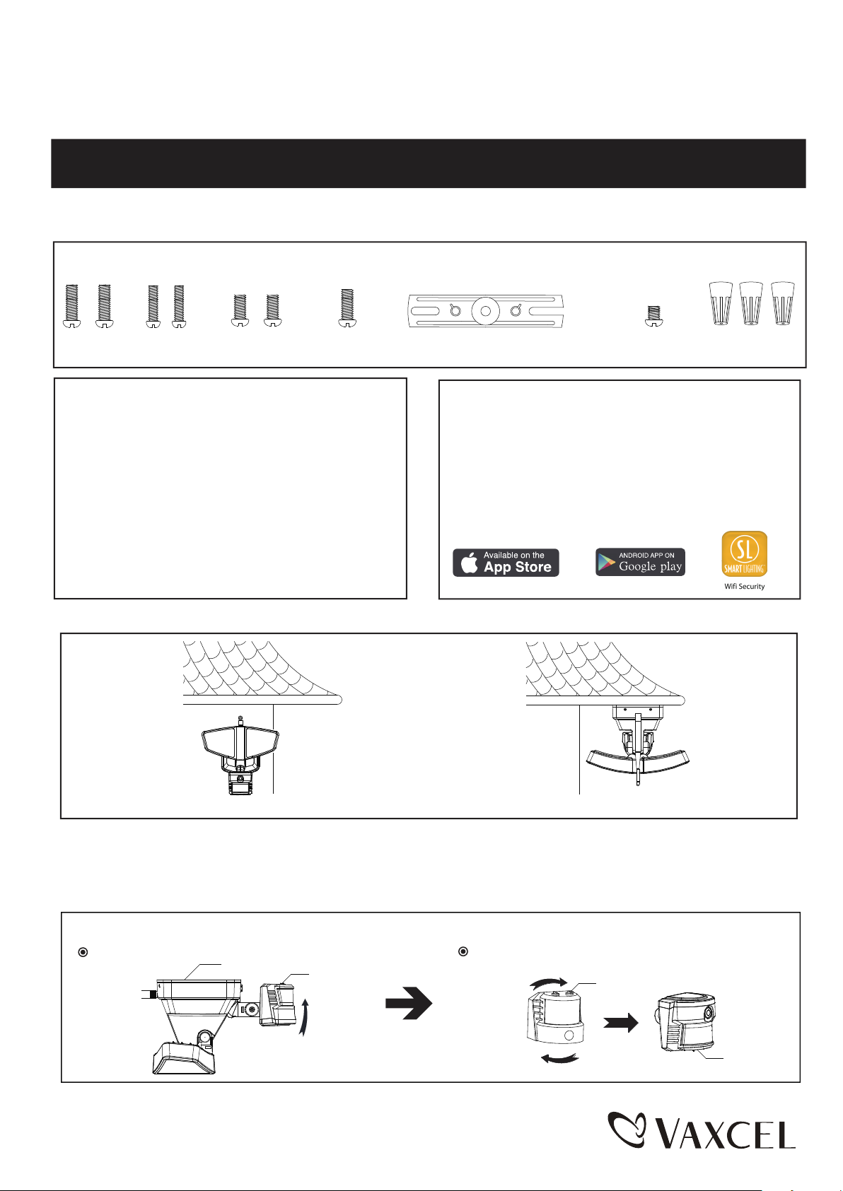
Hardware Package (included):
POWER BEFORE INSTALLING OR SERVICING THIS FIXTURE.
Mounting Screw X2
#8/32X1/2 in
Mounting Screw X2
#6/32 X1/2 in
Important to Know:
1. If you are not familiar with state and local electrical
codes, it is recommended that you consult with a
qualified electrician.
2. This fixture requires a 120 VAC, 60 Hz power
source.
3. For general safety and to avoid any possible
damage to the sensor, be sure the power is
switched "off" before adjustment.
Maximum Wattage: 25 W
Working Temperature Range: - 4°F ~ 113°F
Mounting Screw X2
#10/24 X1/4 in
Mounting Bracket Screw
Mounting Strap
Features:
1. Energy saving LED fixture.
2. Motion sensor: turns light ON automatically when
motion is detected and turns light OFF automatically
when motion stops.
3. Photocell keeps the light OFF during daylight hours.
4. WIFI Camera operation with built-in camera, speaker
& microphone, cloud connectivity, IOS & Android
compatible. (please refer to page 5 to 16)
Note: Fixture can be wall mounted or eave mounted.
Fixture Mounting Screw
Wire Nut X3
Wi Security
Wall Mounted
Read notes section on page 3-4 for addictional information about mounting location of fixture.
Light fixture and sensor should be mounted as shown above when installed (depending upon type of installation)
Before installing the light fixture under an eave, the sensor head must be rotated as shown in the next two steps for
proper operation and to avoid the risk of electrical shock.
For eave mounted only:
Swing the sensor head towards the mounting bracket.
Mounting Bracket
Controls
Rotate the sensor head clockwise 180˚ so the controls face down.
Page 1 / 16
Eave Mounted
Controls
Controls
150616
Mounting Bracket
Mounting Bracket Screw
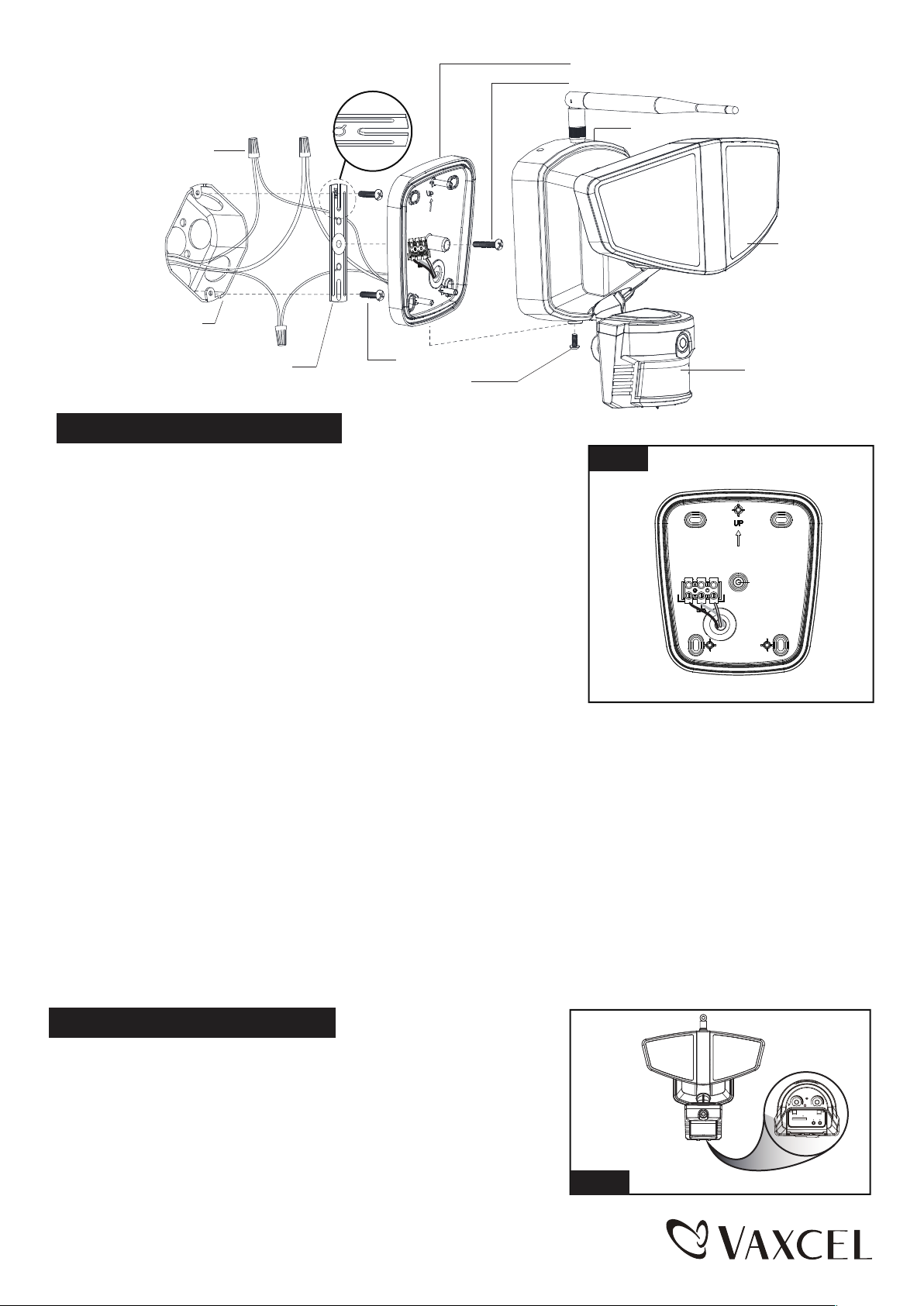
FRONT
Wire Nut
L (Black)
N(White)
Outlet Box
Mounting Strap
Fixture Mounting Screw
Mounting Screw
Installation Steps
Turn off the power at fuse or circuit box.
1. The fixture mounting bracket is pre-assembled on the light fixture.
Unscrew the fixture mounting screw in order to remove the mounting
bracket.
2. Install the mounting strap to the outlet box with the stamped word
“FRONT” facing away from the outlet box, using two mounting
screws that best fit the outlet box. Mounting bracket should sit
flush against wall surface when secured.(Choose one matching
pair of suitable mounting screws from the 3 pairs provided)
Fig. 1
Back Plate
N(White)
Light Head
Sensor
L (Black)
3. Pull out the source wires from the outlet box. Make wire connections
using wire nuts as follows:
---Connect the black wire from the fixture to the “hot” wire from the
power source. (usually black)
---Connect the white wire from the fixture to the neutral wire from the
power source. (usually white)
---Connect the grounding wire from the fixture to the grounding wire
from the power source. (usually green / yellow insulation)
Carefully tuck the wires back into the outlet box.
4. Place mounting bracket against the outlet box, insert the mounting bracket screw through the mounting bracket hole,
thread mounting bracket screw into the center hole of the mounting strap. Tighten the mounting bracket screw securely.
▲ When mounting to a wall, the “UP” arrow must point upward. (See Fig. 1)
▲ When mounting to an eave, the “UP” arrow must point toward the building.
5. Attach the back plate of the light fixture to the mounting bracket, secure it with the fixture mounting screw.
6. With silicone caulking compound, caulk completely around where the mounting bracket meets the wall surface.
CAUTION: Be sure to caulk completely where the mounting bracket meets the wall surface to prevent water
from seeping into the outlet box.
Turn on the power at fuse or circuit box.
Adjusting the Sensor Head:
-- Rotate the motion sensor so the controls face toward the ground.
TIMELUX
10Min
5s
SD
RESET WPS
Page 2 / 16
Fig. 2
150616
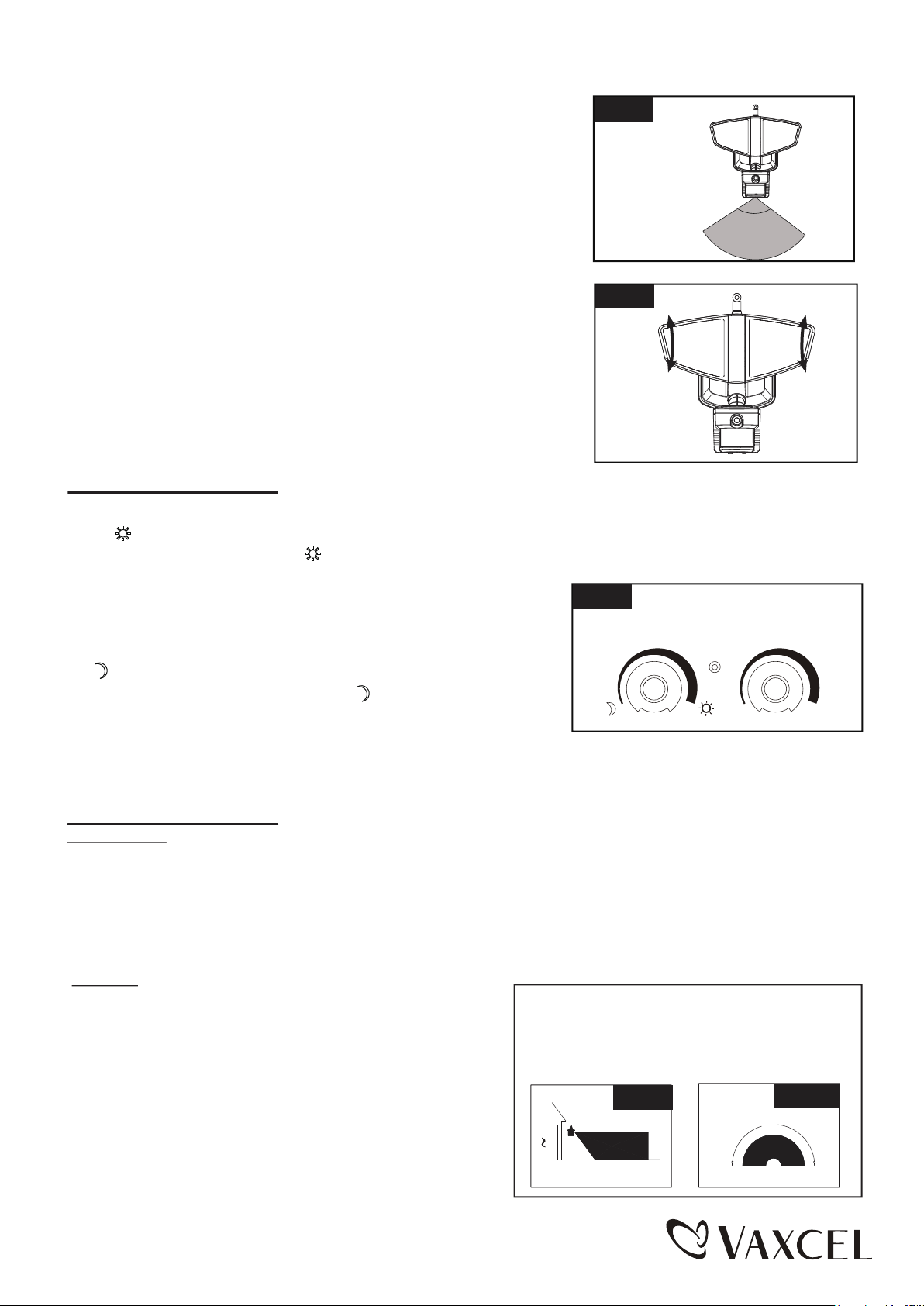
Adjusting the Motion Sensor Detection Zone:
1. Perform a “walk test”: walk in an arc across the front of the motion
sensor.(See Fig.3)
2. The light will come on and the red LED will flash indicating motion
has been detected.
3. Stop, wait for the light to turn off, and then begin walking again.
4. Gently grasp the motion sensor and move it from side to side or up
and down to adjust the detection zone.
Fig. 3
40 ft/110˚
Adjusting the Light Head:
1. Gently grasp the light heads and tilt them up or down, left or right to
adjust the light coverage area. Keep the light heads at least 1˝ (25mm)
away from the sensor.(See Fig. 4)
2. Keep the light heads 30˚ below horizontal to avoid water damage and
electrical shock.
Fig. 4
Function and Operation
Note: When power is first applied, the light will turn on. The sensor will take 30 seconds to warm up.
1. ● “ ” MODE( daytime and nighttime operation)
1. Turn the knob clockwise to “ ”, the light turns on after expiration
of the warm-up period, it stays on when motion is detected.
When motion is no longer detected, it remains on for the
predetermined shut-off delay time you set (5s~10 min), and then
turns off automatically.
Fig. 5
TIMELUX
2. “ ” MODE(nighttime operation only)
1.Turn the knob counterclockwise to “ ” ,the light turns on after
expiration of the warm-up period, it stays on when motion is
detected. When motion is no longer detected, it remains on
for the predetermined shut-off delay time you set (5s~10min), and then turns off automatically.
2. The light will turn off automatically at dawn.
5s
10Min
Customization Options:
Shut-off Delay
● The shut-off delay is the length of time the light will stay at brightness after motion is detected.
● You can set the shut-off delay by rotating the time delay knob arrow so it points to the desired time setting (from
5 seconds to 10 minutes). To increase the shut-off delay, turn the knob clockwise. To decrease the shut-off delay,
turn the knob counterclockwise.
Notes:
1. The sensitivity of the motion sensor will increase as the
environmental temperature gets cooler. For best
performance, gently clean the lens with a soft cloth every
1 or 2 months to assure maximum sensitivity.
2. For best performance, install fixture at least 8 feet above
the ground. At such a height, the fixture will provide a
detection distance of up to 40 feet at 77 degrees
Fahrenheit. (See Fig.6)
3. The sensor detects movement across a detection range
of 180 degrees. (See Fig.7)
Where you install your fixture is important:
Be sure the light is mounted straight on the wall
or eave; otherwise, the detection distance may
be limited.
Fig. 7
180˚
12.0'
8.0'
20'
Fig. 6
40'
Page 3 / 16
150616
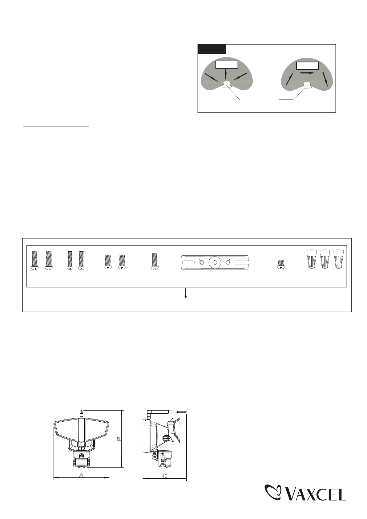
4. The sensor will be more sensitive to motion across its
Fig. 8
detection path than motion directly towards it. (See Fig.8)
Motion
Motion
5. To reduce possible nuisances, do not mount the fixture
near a heat source like an air conditioner, vent or furnace
exhaust, or in a direction facing any reflective object or
other nearby light source.
Sensor
Least sensitive
Most sensitive
Troubleshooting
---The light does not come on at all:
1. Make sure the wall switch and circuit breaker are on.
2. Make sure the wiring is correct.
3. Cover the sensor with dark color cloth to verify that the ambient light level is not too high.
---Light flashs:
Cover PIR sensor len with black cloth / aluminum foil paper, if the light function is normal, then check for following.
1. Excessive heat around the detection area.
2. The PIR sensor is facing a tree or other obstacle.
3. The PIR sensor is facing a fan or air conditioner.
---PIR sensor will not activate during daytime:
1. Adjust the dusk level control to daytime(full clockwise)
The following parts are available for re-order if damaged or missing.
Mounting Screw X2
#8/32X1/2 in
Mounting Screw X2
#6/32 X1/2 in
Mounting Screw X2
#10/24 X1/4 in
Mounting Bracket Screw
Assembly Kit
5327MM (1 SET)
Mounting Strap
Fixture Mounting Screw
Wire Nut X3
5-YEAR LIMITED WARRANTY:
All products are warranted to be free of defects in material and workmanship for five (5) years from date of
purchase. This warranty is limited to the correction of any such defect, or the replacement of any such defective
item(s), provided that: (a) we are properly notified and consent to return of the item(s) in question:(b) the item (s)
is / are returned with proof of purchase date; and (c) it is found upon inspection by us that the item (s) is / are defective
as noted above. This warranty dose not cover labor costs, consequential damages, nor dose it apply to any item(s) that
have been improperly installed, overloaded, altered, or otherwise abused by the customer, its agent(s) or emplyee(s).
Finishes are specially excluded from the terms of this warranty since they are subject to environmental maintenance
deemed beyond our control. Other than the described obligation, we assume no further liability with respect to the sale
or use of our products.We make no warranty, express or implied, and disclaim any warranty of merchantability or fitness
for a particular purpose.
A: 9-3/4"
B
B: 9-3/4"
C: 6-1/2"
A
C
Page 4 / 16
150616

Software Setting
Brief Introduction of Wifi Security Light
Introduction of Wifi Security Light.
1. The Wifi Security Light combines an LED security floodlight with an intergrated wireless camera device.
2. The basic function of an wifi camera is to transmit remote video data through a computer network. Using the H.264
hardware compression technigue, the transmission speed of high quality video images across the network & internet
can reach 25 frames per second real time.
3. The transmission of wifi camera video data is based on TCP/IP protocol. The build-in web server supports Firefox and
Chrome remote configuration and update firmware. You can use the Wifi Security Light to monitor areas in your home
and office, or control the camera through network and manage images.
Product Features
1. Powerful high- speed video protocol processor
2. High-sensitivity 1/4˝ CMOS sensor
3. Maximum 1.0 megapixel image resolution
4. High-brightness LED illumination night vision
5. Optimized H.264 video compression transmission
6. Multi-level user management and password setting
7. Build-in Web server that can be accessed by users through IE browser
8. Wireless network compatibility (WI-FI/ 802.11/b/g/n)
9. Dynamic DNS (DDNS), UPnP and internet (ADSL, broadband cable modem)
10. Bi-directional audio monitoring
11. Still image capture
12. Multiple network protocols: HTTP/ TCP/ IP/ UDP/ STMP/ DDNS/ SNTP/ DHCP/ FTP
13. Remote system update
14. Maximum capacity of 32 GB SD memory card. (SD card sold separately)
Advanced Features
1. Multiple transport protocols: Wifi Security Light supports many protocols, for example, TCP/ IP, SMTP and HTTP.
When the Wifi Security Light alarm is triggered, it can send e-mail to you automatically.
2. PIR sensor: Can automatically detect and trigger image recording and transmission.
3. Wifi Security Light also provides dynamic DNS function.
4. Advanced user management: Allows only authorized users to access the live video of Wifi Security Light.
Hardware Information of the Product
1. External View of the Product:
Indicator Status:
■ System start-up indicator: The blue indicator will be on after it is powered on for 15 seconds, and it will enter
the current mode indication after the indicator is normally on for 20 seconds.
■ AP mode: The blue indicator flashes with an interval of 1 second.
■ STATION mode: The blue indicator remains on.
■ Alarm: The red indicator flashes with an interval of 1 second.
■ WPS setting mode: The blue indicator flashes with an interval of 0.5 second.
■ Factory reset mode: The red indicator remains on and the blue indicator flashes with an interval of 0.3 second.
2. Operating Methods of Buttons:
RESET button: Press the button and hold for 3 seconds to enter the AP mode, hold for 8 seconds to enter the
■ AP/
factory reset mode. (See Fig.9)
■ WPS button: Press and hold the button for 5 seconds to enter WPS. (See Fig.9)
Page 5 / 16
150616

Fig. 9
Ambient Light
Induction Setting
SD Card
SD
TIMELUX
5s
RESET WPS
10Min
Time Setting
WPS
Reset
Phone
Phone
Pc
Operating Methods of Buttons
A
Wifi Security Light
Router Moden Internel
B
Phone
PC
■ The connection between Wifi Security Light and other devices is through WIFI.
■ As shown in the above figure: Connection mode A is when a phone or PC is connected to the Wifi Security Light
directly. Wifi Security Light must be set to the “factory reset” or AP mode to establish this type of connection.
■ The connection method: First you need to disconnect the current wireless network from your device ( pc or phone).
Scan for the Wifi Security Light’s WIFI hotspot. This will be listed as “IPCAM-XXX” or similar. The default password
is “null”, the function of this connection is to operate the built-in WEB server of the Wifi Security Light directly so as
to set relevant parameters, including configuring Wifi Security Light to the router. When using the connection of Wifi
Security Light and internet for first time, its WIFI should be connected to the router in this way.
■ Connection mode B is that the user has installed the Wifi Security Light, and the client software in the phone or PC
can be used to view the monitoring screen in Wifi Security Light.
Quick Confiuration of Wifi Security Light
1. Quick Configuration of Wifi Security Light
■ When this product (Wifi Security Light) is used for the first time, it should be connected to a router with internet access.
This process is called the quick configuration of Wifi Security Light. If the user wants to change the connecting router,
set the Wifi Security Light in the “AP” mode and then conduct the quick configuration of Wifi Security Light.
2.1 The Method of Configuring Wifi Security Light through mobile device
■ Search “Wifi Security” on IOS APP store or Android Google Play. Install the “Wifi Security” APP onto the device.
It’s available for Apple and Android device.
Wi Security
■ Select the IPCAM_XXXXXX connection in the WIFI networking bar of the phone, leave the password field blank.
■ Run the APP. (Take Android for example as below. IOS will be slightly different)
■ Select “Click here to add camera”.
■ Select “ Wifi Wizard add”.
■ Follow the prompt and select “Next”.
Wifi
Page 6 / 16
150616

■ The password should be empty, tap on password
held and select “Next” .
Input route password then
click Next
■ Choose router.
Configuration Method of WPS:
Press the WPS button in the panel of Wifi Security Light
for 5 seconds. The blue indicator will flash rapidly after
entering into the WPS mode. Then press the WPS button
on the router which you would like to connect to Wifi
Security Light (refer to router manual for instructions on
WPS mode operarion).
2.2 Usage of Phone Client Application
Software
■ Enable phone network function, install and run “Wifi
Security” software.
■ Click “Click here to add camera”
■ Input the WIFI password of the router and select “Next”.
■ Input the password of the camera default is blank and
click “Save”. Wifi Security Light will restart. After
restarting, the software can be connected with Wifi
Security Light to see the screen. (you will need to
reconnect to normal WIFI network)
■ Select different quick adding modes.
NOTE: You can find the QR code on the light fixture.
■ Input username and password and Save
Custom Camera Name
The password of Camera default
is blank, if has been set, user
need input it.
Page 7 / 16
150616

■ The camera has been successfully added if the
following interface appears.
LCAM-000839-CJCEM
■ Settings interface
■ User Setting interface
Explanations of menu in the main interface.
Enter
Video
Online
Camera Main
Interface
status
Alarm
Settings
Display the image
and video files
saved
SD
Status
WIFI Signal
Camera Name
Camera Operation
Setting
ID
Software Settings
The admin user has the highest
administrative authority, can set the
IPCAM password here.
IPCAM setting other
guests access
Page 8 / 16
150616

■ User Setting interface
■ Surveil the video interface
Audio Recording
Take Photo
Video Screen Settings
Video Format Settings
Record Video
Intercom
Stop
3.1 The Method of Configuring Wifi
Security Light through PC
■ Install the “Wifi Security” software in PC. (Please
refer to the CD provided)
■ Select the IPCAM_XXXXXX connection in the WIFI
networking bar of PC, the password is null.
■ Run the “Wifi Security” software.
IP Camera
■ Double-click the IP address in the following prompt
box and input the user name “admin” and password
“null” into the box.
■ Select “ RC Plug-in Mode” in the prompt box below.
Page 9 / 16
150616

■ Select “ Device Management” in the prompt box below.
■ First select “wireless setting” in the following prompt box and select “search” on the right. Then the avialable nearby
WIFI hot spots will appear. Select the user’s router and in the shared password box input the WIFI password. Click
“set” and confirm. Wifi Security Light will count down and restart. After restarting, the client software can be connected
with Wifi Security Light to see the screen.
■ Reconnect to normal wireless network.
■ Operation Guide
Live Video
When logging into the system for the first time, IE will prompt “Install the plug-in from Player ActiveX” automatically.
Video can be seen after installing it according to the prompts in the page.
■ The picture is the homepage after logging into the camera, and the menu page of live video. The serial numbers in
the picture are explained as follows:
Page 10 / 16
150616

Serial
No:
0
1
2
3
4
5
6
Name
Menu b ar
Switch of
multichannel
device
Current
device statu s
Login
device statu s
User
infor mation
Switch of
multiple dev ice
(2409M)
Audio and vi deo
optio ns as well
as reco rd an d
snapsh ot
Explanation
There are the liv e video and devi ce
management s wift menus at the top
left c orner of th e main interface
The live video of the camera can v iew 9 channels
at the same time at most
The co nnection, video, audio, talk and recording
status of the cu rrent device.
Recording, alarm and storage. It will popup more
status info rmatio n when
the mouse moves to it.
The username of the current login user:
Switch among one device, four devices a nd ni ne
devices.
Adjust the audio and video of the camera, live video
playing and basic attribute setting of the camera
1. Con trol the pl aying or stop of camera video
2. Con trol the op en and close of camera audi o
3. Sta rt dialogue
4. Loc al recordin g. Th e time can select 10,
5. Device recordi ng
ing, the camera ha s the options of
6. Whe n snapsh
conti nuous captu re mod es of 3, 4, 5 an d 6 photos
7. Setting of camera parameters
ot
■ Basic status of the device
2nd,August.2014 Saturday
2nd,August.2014 Saturday
2nd,August.2014 Saturday
2nd,August.2014 Saturday
2nd,August.2014 Saturday
2nd,August.2014 Saturday
2nd,August.2014 Saturday
2nd,August.2014 Saturday
2nd,August.2014 Saturday
2nd,August.2014 Saturday
Device Log which records the last 100 device logs of
the camera.
■ Basic setting
Device
7
parame ter se tting
60HZ
Camera parameter setting
1. Adj ust the camera resolution ( 4 options)
2. Adj ust the camera buffer time
3. Adj ust the camera frequen cy (50HZ, 60HZ)
4. Sel ect ca mera mirror and flip
5. Set the bright ness of camera
6. Set the sharpn ess of came ra
7. Set the contrast of camera
8. set th e saturation of camera
9. Set the white balan ce
10. Restore defaults
■ Device Management
Device Status
Alias Setting
User Setting
Page 11 / 16
■ User Settings: It can set eight users at most as
admistors or visitors. It can also set the permissions
on their video, snapshot, device record, audio,talk and
control.
150616

■ Setting requirements of username and password, the
username, being a required filed, can not be“admin”.
For the group of adminstrators, the password should
have six characters at least and include figures and
letters.
■ Setting allows access:
■ Multiple device setting
It can set eight devices at most and can connect eight
multiple devices at the same time.
Http Port Settings
Wireless Settings
Network Settings
If the router connected by the device has the function of
DHCP server, you can check “Obtain IP from DHCP
Server”. Otherwise, fill in the network paraments as
shown in the figure below manually.
Http Port: In most cases, you can set it as 80. However,
if your internet service provider stops this port, you may
have to set it as other optional values (from 0 to 65535,
do not set it as the same value as gateway), for example,
8080,85,etc.
IP Settings
PPPoE Settings
DDNS Service
■ DDNS Service: The system supports the protocols
provided by DynDNS.org,3322.org, Oray.net,9299.org,
No-ip.com and myfoscan.org in DDNS service.
■ Username and password: The username and password
you used when applying for domain name.
■ DDNS Domain: The domain you applied for the device.
Page 12 / 16
150616

The setting page of mailbox
Alarm Settings
■ Alarm Settings: Set enable alarm schedule, three alarm
methods can be enabled, namely, motion detect, trigger
detec and sound detec, it can also set the sensitivity.
Alarm Action Settings:
■ Configure the e-mail sent and received. When there is
an alarm or the IP address of the device changes, the
receiver will receive the e-mail of the sender.
■ Note: Send alarm capture through e-mail. Check Alarm
Settings -> Mail Notification after Alarm.
■ Sender: The mailbox to send e-mails.
■ Receiver: The mailbox to receivecaptures and IP
address. Four receiving mailboxes can be set at most.
■ SMTP Server: The SMTP server to send mails.
■ Need Authentication: If the sender needs to be
authenticated, please fill in the correct username and
password.
■ Mail Test: Fill in the above mail parameters and click
“Set” for test. You can see the test result in a pop-up
window and receive a test mail in the receiving mail
box.
■ Mail Notify Internet IP Address: If this item is checked,
when internet IP or port is set, please make sure that
the port is mapped in router correctly through the virtual
server function of UPNP or router. (take an example for
the contents sent in the mail, IPCAM’s url is
http://119.123.207.96:9002)
■ Alarm Action Settings: The actions enabled after alarm.
Record Settings
Page 13 / 16
150616

Record Settings, Edit Schedule
Record Settings and Record File Management
■ Set the date and time of camera access and the IP
access permission.
Dictionary attack settings
2nd August 2014 Sat
2nd August 2014 Sat
2nd August 2014 Sat
2nd August 2014 Sat
SD memory Card Record File Management. Search the
file recorded, download it to local computer, and then you
can watch it directly. (The player is VLC. Download
the lastest version of VLC media player from
http://www.videolan.org)
Security Settings
Tools
■ Tools: Backup Settings, Restore Settings, Upgrade
System Firmware and Upgrade Embedded Htmls.
3.2 Usage of PC Client Application
Software
■ Install and run the “ Wifi Security” software. Enter
the username and password.
Page 14 / 16
150616

■ Main control interface
Alarm record bar
Camera information
bar
■ P2P Settings
Language selection
■ Management window
Select add camera here
■ Control window
Camera information added
Select add camera here
FAQ Changing the connected router
Advance Setting to WEB
There are two methods to change the connected router:
1. First set the
Wifi Security Light
into “AP” mode and implement
Wifi Security Light
quick configuration.
2. Use the administrator rights to find the wireless network setting menu in the client software and modify it.
If I forgot my password:
Press and hold the RESET button in the
Wifi Security Light
panel for 10 seconds while the device is on. And all
parameters will restore to default values (factory values). The factory user name is admin and password is null.
If you face any problem, please check your network firstly
Check the status indicator of network devices (concentrator, switch and network card). If they are abnormal, check your
networking.
IP Address Error
Check the IP address of the device to see if it is in the same subnet segment with your local computer: open My
Computer > Control Panel > Network & Dial-up Connection > Local Network > Internet Protocol (TCP/IP), examine
subnet mask, IP address and gateway. When setting the IP address of the device manually, please make sure that
they are in the same subnet. Otherwise, it can not visit the device normally.
Page 15 / 16
150616

Network Problem
Network Connection Problem
Mke sure that your HTTP server software is configured correctly and runs well. If you have used any firewall software,
make sure that the 80 port can be accessed externally. If you are using shared ADSL router, please ensure that the
suitable port forwarding is set. (Please refer to the users’ manual of your router). If these do not any problem, it may be
because your internet service provider blocks the 80 port – to prevent worm virus, like Code Red. In this case, you may
have to modify your port (for example, 8080).
Network Bandwidth Problem
The frame rate of images depends on the following factors: 1. network bandwidth; 2. performance of computer and
network environment; 3. the quantity of users logging in the device (too much user acess will lower the frame rate of
images); 4. using a switch or a concentrator (use a switch rather than a concentrator if there are many devices). The
quality of images transmitted will be better if the network bandwidth is broader.
No Image Displayed in ActiveX Plug-in
Video images are received and displayed to users through ActiveX plug-in. If the installation is not correct, the images
may not be displayed. To solve this problem, there are two methods:
1) Install “IP Camera Tool”, then the ActiveX plug-in will be installed at the same time (recommended).
2) Download and install Active X-plug-in and modify the security settings of IE browser when visiting the device for the
first time.
Set three options in “ActiveX widget and plug-in” “Custom Level” “Security” “Internet Options” “Tools” “IE” browser
as “Enable”:
Enable: download unsigned ActiveX widget
Enable: conduct initialization and script running for the ActiveX widgets which do not signed as safe
Enable: run ActiveX widget and plug-in
Browser Faces a Problem
It is recommended to use FireFox browser tologin the device.The download link of FireFox browser:
Http://www.firefox.com.
FCC Certification Requirements
Caution:Any changes or modifications in construction of this device which are not expressly approved by the party
responsible for compliance could void the user’s authority to operate the equipment.
This device complies with part 1S of the FCC Rules. Operation is subject to the following two conditions: (1) This
device may not cause harmful interference, and (2) This device must accept any interference received, including
interference that may cause undesired operation.
The manufacturer is not responsible for any radio or TV interference caused by unauthorized modifications to this
equipment. Such modifications could void the user’s authority to operate the equipment.
This equipment has been tested and found to comply with the limits for a Class B digital device, pursuant to Part 1S
of the FCC Rules. These limits are designed to provide reasonable protection against harmful interference in a
residential installation. This equipment generates, uses and can radiate radio frequency energy and, if not installed
and used in accordance with the instructions, may cause harmful interference to radio communications. However,
there is no guarantee that interference will not occur in a particular installation. If this equipment does cause harmful
interference to radio or television reception, which can be determined by turning the equipment off and on, the user
is encouraged to try to correct the interference by one or more of the following measures:
- Reorient or relocate the receiving antenna.
- Increase the separation between the equipment and receiver.
- Connect the equipment into an outlet on a circuit different from that to which the receiver is connected.
- Consult the dealer or an experienced radio/ TV technician for help.
The antenna(s) used for this transmitter must be installed to provide a separation distance of at least 20cm from
all persons.
Page 16 / 16
150616
 Loading...