

T0099 / T0100 --- Page 1 / 5
Important to Know:
1. If you are not familiar with state and local electrical
codes, it is recommended that you consult with a
qualified electrician.
2. This fixture requires a 120 VAC, 60 Hz power
source.
3. For general safety and to avoid any possible
damage to the sensor, be sure the power is
switched "off" before adjustment.
Maximum Wattage: 25.5 W
Working Temperature Range: -40F ~ 1130F
ASSEMBLY AND INSTALLATION
INSTRUCTIONS
NOTES: 1. Before installing, consult local electrical codes for wiring and grounding requirements.
2. READ AND SAVE THESE INSTRUCTIONS.
T0099 / T0100
Features:
1. Energy saving LED fixture.
2. Motion sensor: turns light ON automatically when
motion is detected and turns light OFF automatically
when motion stops.
3. Photocell keeps the light OFF during daylight hours.
4. When in manual override mode, use wall switch
to keep the light ON during the night.
WARNING:
TO AVOID RISK OF ELECTRICAL SHOCK, BE SURE TO SHUT OFF
POWER WHILE INSTALLING OR SERVICING THIS FIXTURE.
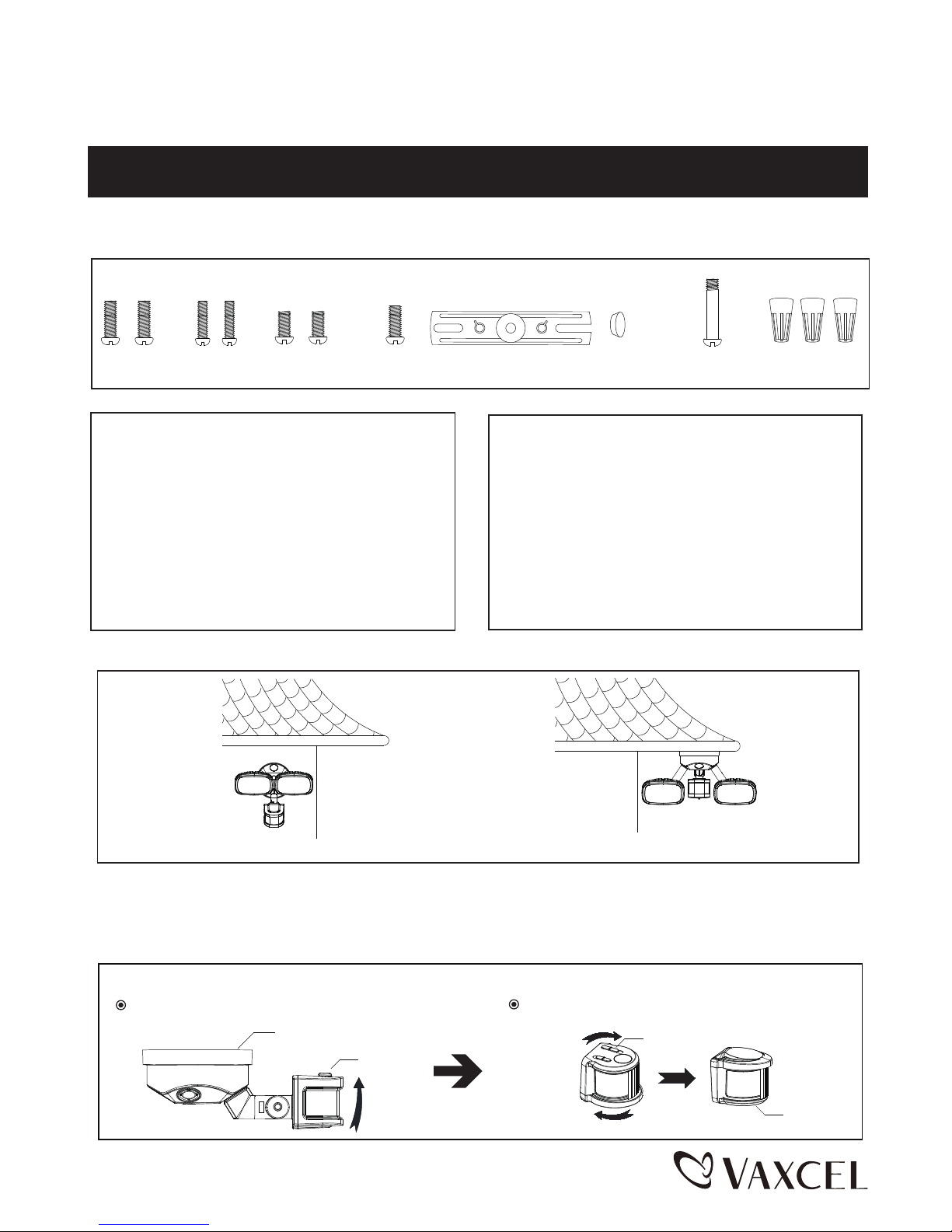
Note: Fixture can be wall mounted or eave mounted.
Wall Mounted
Eave Mounted
Light fixture and sensor should be mounted as shown above when installed (depending upon type of installation)
Before installing the light fixture under an eave, the sensor head must be rotated as shown in the next two steps for
proper operation and to avoid the risk of electrical shock.
For eave mounted only:
Swing the sensor head towards the mounting bracket.
Rotate the sensor head clockwise 180˚ so the controls face down.
Controls
Mounting Bracket
Controls
Controls
Hardware Package (included):
Mounting Screw (A)
Mounting Screw (B)
Decorative cover (F)
Mounting Bracket Screw (D)
Fixture Mounting Screw (G)
Mounting Strap (E)Mounting Screw (C)
Wire Nut (H)
140919
T0099 / T0100 --- Page 2 / 5
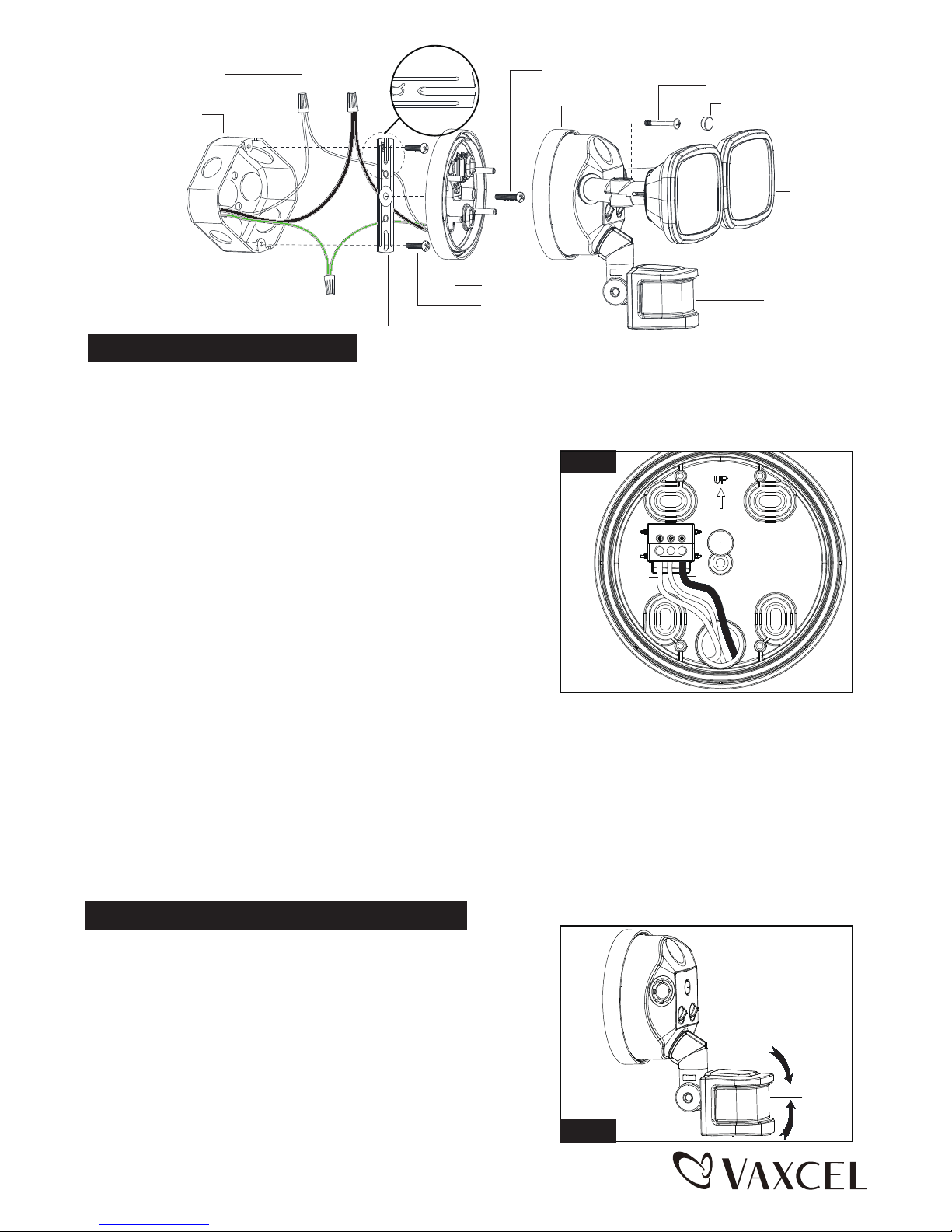
Sensor
1. Aim sensor head toward desired detection area, maintaining a
5° - 40° downward angle to allow moisture to drain.
Note: Make sure sensor head is positioned with control knob facing
towards the ground.
2. You can move the sensor head up and down to change the coverage
area. (See Fig. 2) Walk through the detection zone at the farthest
distance you wish to detect motion.
Note: Range set too high may increase false triggering.
(See Fig. 3 and Fig. 4 on Page 3)
Adjusting the Sensor Head:
Turn on the power at the main fuse or circuit breaker box.
sensor
Fig. 2
Installation Steps
Turn off the power at fuse or circuit box.
Mounting Strap (E)
Mounting Bracket
Outlet Box
Wire Nut (H)
Back Plate
Mounting Screw (A)
Light Head
Fixture Mounting Screw (G)
Mounting Bracket Screw (D)
FRONT
Decorative cover (F)
1. The fixture mounting bracket is pre-assembled on the light fixture. Unscrew both the decorative cover and the fixture
mounting screw in order to remove the mounting bracket.
2. Install the mounting strap to the outlet box with the stamped word “FRONT” facing away from the outlet box, using
two mounting screws that best fit the outlet box.
3. Pull out the source wires from the outlet box. Make wire connections
using wire nuts as follows:
---Connect the black wire from the fixture to the black wire from the
power source.
---Connect the white wire from the fixture to the white wire from the
power source.
---Connect the grounding wire from the fixture to the grounding wire
from the power source. (usually green / yellow insulation)
Carefully tuck the wires back into the outlet box.
4. Place mounting bracket against the outlet box, insert the mounting
bracket screw through the mounting bracket hole, thread mounting
bracket screw into the center hole of the mounting strap. Tighten the
mounting bracket screw securely.
▲ When mounting to a wall, the “UP” arrow must point upward. (See Fig. 1)
▲ When mounting to an eave, the “UP” arrow must point toward the building.
5. Attach the back plate of the light fixture to the mounting bracket, secure it with the fixture mounting screw.
6. Push the decorative cover firmly into the fixture mounting screw hole on the light fixture.
7. With silicone caulking compound, caulk completely around where the mounting bracket meets the wall surface.
CAUTION: Be sure to caulk completely where the mounting bracket meets the wall surface to prevent water
from seeping into the outlet box.
Fig. 1
L (Black)
N (White)
GND
140919
 Loading...