

Page 1
ZAFIRA
Operation, Safety and Maintenance
Owner’s Manual
Page 2

Data specific to your vehicle
Please enter your vehicle’s data here to keep it easily accessible. This information is available under the section "Technical data" as well as
on the identification plate and in the Service Booklet.
Fuel
De sign ation
Engine oil
Grade
Viscosi ty
Tyre pressure
T y re si ze with up to 3 pe ople with full lo ad
Summ er tyres Fro nt Rear Fro nt Rear
Winter tyres Fro nt Rear Fro n t Rear
Weights
Permissible Gross Vehicle
Weight
– EC kerbweight
=Loading
Page 3

Your Zafira
is an intelligent combination of forwardlooking technology, impressive safety,
environmental friendliness and economy.
It now lies with you to drive your vehicle
safely and ensure that it performs
perfectly. This Owner’s Manual provides
you with all the necessary information to
that end.
Make sure your passengers are awa re
of the possible risk of accident and injury
which may result from improper use of the
vehicle.
You must always comply with the specific
laws of the country that y ou are travelling
through. These laws may differ from the
information in this Owner’s Manual.
When this Manual refers to a workshop
visit, we recommend your Vauxhall
Authorised Repairer.
All Vauxhall Authorised Repairers provide
first-class service at reasonable prices.
You will receive quick, reliable and
individual service.
Experienced mechanics, trained by
Vauxhall, work according to specific
Vauxhall instructions.
The Own er’s Ma nual shou ld alwa ys be ke pt
in the vehicle: Ready to hand in the glove
compartment.
Make use of the Owner’s
Manual:
z The "In Brief" section will give you an
initial overview.
z The table of contents at the beginning of
the owner’s manual and within the
individual chapters will show you where
everything is.
z Its index will help you find what you
want.
z It will fa miliarize y ou with the
sophisticated technology.
z It will increase your pleasure in your
vehicle.
z It will help you to handle your vehicle
expertly.
The Owner’s Manual is designed to be
clearly laid-out and easily understood.
This symbo l sign ifies:
6 continue reading on next page.
3 The asterisk signifies equipment not
fitted to all vehicles (model variants,
engine options, models specific to one
country, optional equipment, Genuine
Vauxhall Parts and Accessories).
9 Wa rn ing
Text marked 9 Warning provides
information on risk of accident or injury.
Disregard of the instructions may lead
to injuries or endanger life. Inform your
passengers accordingly.
Yellow arrows in the illustrations serve as
points of reference or indicate some action
to be performed.
Black arrows in the illustrations indicate a
reaction or a second action to be
performed.
Directional data, e.g. left or right, or front
or back, in the descriptions always relate to
the direction of travel.
We wish you many hours of pleasurable
driving
Your Vauxhall Team
Page 4

Page 5

Contents
Comm itment to cu stomer
satisfaction:
Our ai m: to keep you happy with your
vehicle. All Vauxhall Authorised Repaire rs
offer first-class service at competitive
prices. Experienced, factory-trained
technicians w ork according to factory
instructions. Your Authorised Repairer can
supply you with GEN UINE VAUXHALL-
APPROVED PARTS, which have undergone
stringent quality and precision checks, and
of course useful and attractive
VAUXHALL-APPROVED AC CESSORIES.
Our name is your guarantee!
For d eta ils of the
Vauxhall Authorised Repairer Network,
please ring this number; 0845 090 2044
In Brief ....... ......... ........ ......... ......... ......... ..... 2
Locks, Doo rs, Windows .. .... ......... ..... .... .. 30
Seats, Interior ..... .... ............. ..... .... ........... 4 9
Instrum ents, Controls ..... ......... ......... ...... 8 2
Lighting ......... ..... .... ......... .... ..... .... ......... 105
Infotainment Syste m ...... .... ......... ......... 112
Climate Control . ........ ......... ......... ......... 114
Driving and Operation ............ .... ..... .... 131
Self-help, Ve hicle Care ... .... .............. .... 170
Service, Mainte nance ..... .... ......... ......... 198
Te chnical Data ...... .... ..... ............. ..... .... 210
Index ..... ..... ......... ........ ......... ......... ......... 230
Page 6
2In Brief
In Brief
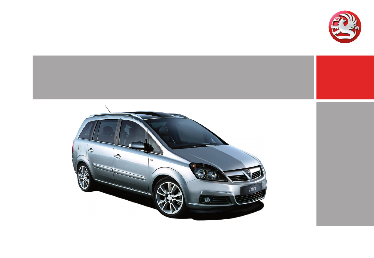
To unlock and open the vehicle:
Press button q, pull door handle
6 Door locks – page 30,
Keys – page 30,
Electronic immobiliser – pa ge 30,
Radio frequency remote control – page 32,
Central locking system – page 37,
Anti-theft locking system 3 – page 38,
Vauxhall alarm system 3 – page 42.
Unlock vehicle and open with
the Open&Start system 3:
Electronic key in vehicle
reception range,
Pull handle
6 Open&Start system 3 – page 33.
Page 7
3In Brief
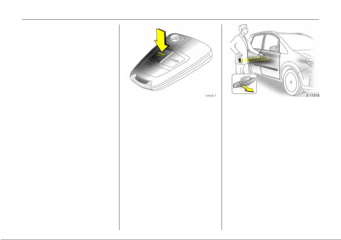
Unlock luggage compartment
and open:
Press button
q on the remote
control, or for the Open&Start
system 3
place electronic key in the
vehicle reception range,
operate button bene ath han dle
6 Open&S tart sy ste m 3 – page 33,
Radio frequency remote control – page 32,
Central locking system – page 37,
Vauxhall alarm system 3 – page 42.
To adjust front seat:
Pull handle , slid e sea t,
release handle
6 Seats – page 49,
Seat position – p age 50.
9 Warning
Important: Do not sit nearer than
10 inches (25 cm) from the steering
wheel, to permit safe airbag deployment.
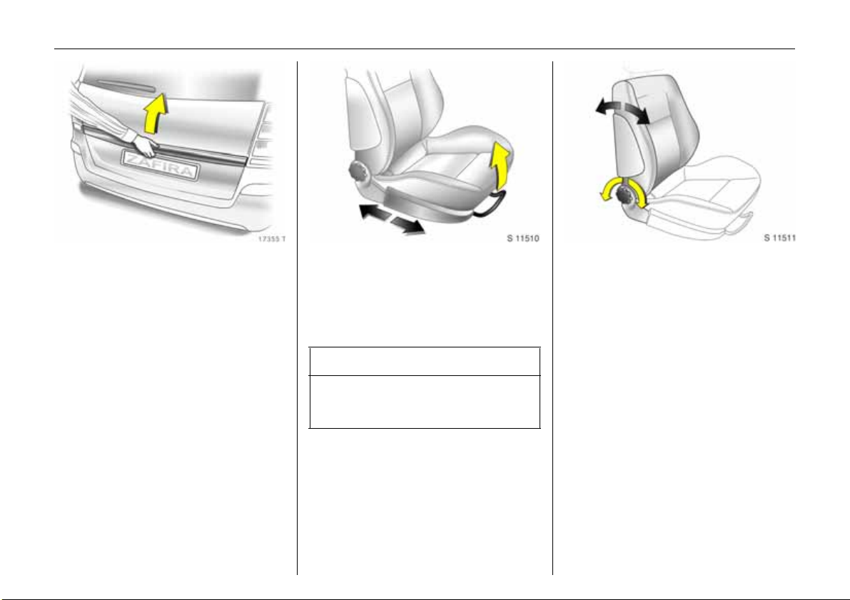
Adjust front seat backrests:
Turn handwheel
Move seat backrest to suit sea ting position.
Do not lean on seat when adjusting.
6 Seats – page 49,
Seat position – page 50,
Folding down the front passenger’s seat –
page 57.
Page 8
4In Brief
Adjusting front seat height 3:
Operate levers on outboard side
of seats
Lever pumping m otion
up: Seat higher
down: Seat lower
6 Seats – page 49,
Seat position – page 50.
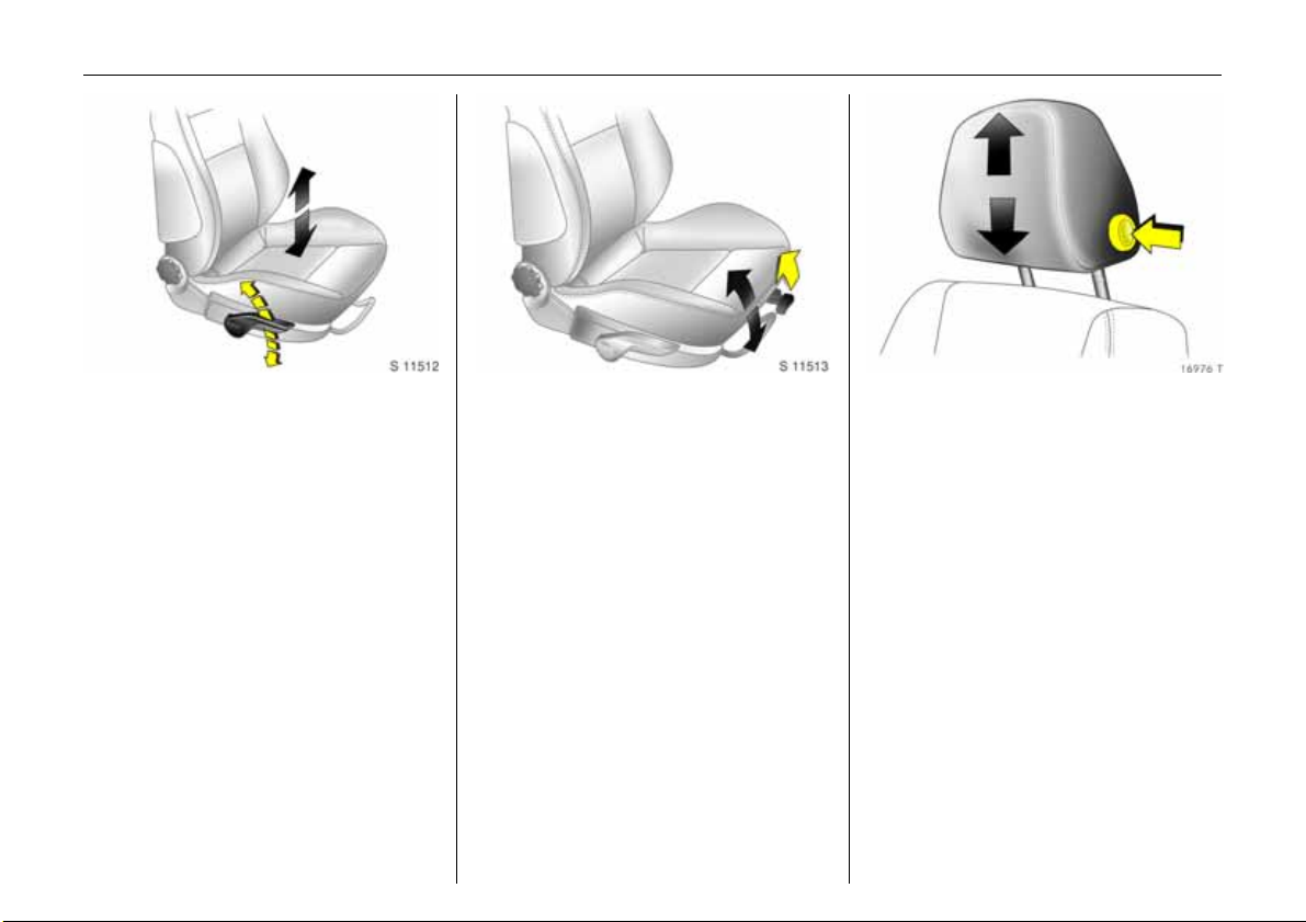
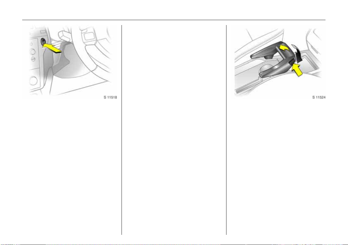
To adjust front seat
inclination 3 :
Pull inner lever on front of seat,
adjust inclination, release lever,
engage seat in position
Adjust inclination b y shifting body weight.
6 Seats – page 49,
Seat position – page 50.
Adjusting height of head
restraints of front seat and
outboard seats in second row:
Press knob to release, adjust
height, engage
6 Head restraints – page 51,
Adjust rear centre head restraint and third
seat row head restraints – page 51,
Head restraint position – page 51,
Removing the head restraint – page 52.
Page 9
5In Brief
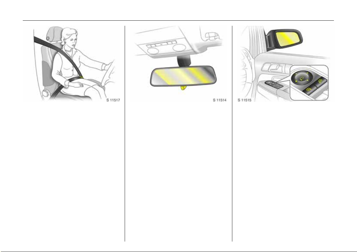
Putting on seat belt:
Pull out the seat belt smoothly,
pass it over your shoulder and
click into the belt buckle
The seat belt must not be twisted at any
point. The lap be lt must lie snugly against
the body. The front seat backrests must not
be tilted back too far (recommended
maximum tilting angle approx. 25°).
To release belt, press red button on belt
buckle.
6 Three-point seat belt – page 63,
Airbag system – page 69,
Seat position – page 50.
Adjusting interior mirror:
Swivel mirror housing
Swivel lever on underside of mirror housing
to reduce dazzle at night.
6 Mirrors – page 46, automatically
dipping interior mirror – page 46.
Electrical exterior mirrors 3,
adjust:
Four-way switch in driver’s door
Push right or left mirror switch: four-way
switch adjusts relevant m irror.
6 Mirrors – page 45,
Aspherical exterior m irror – page 45,
Fold exterior mirror – page 45,
Heated exterior mirrors – pages13, 116.
Page 10
6In Brief
Page 11

7In Brief
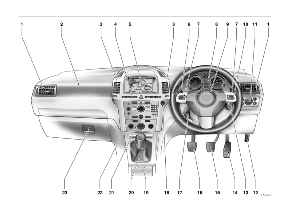
Page
1 Side air v ents ............ ..... ........ ......... 115
2 Fron t pa ssenge r’s airbag . ......... ..... 6 9
3 Centre air v ents .... ......... ........ ........ 115
4 Left heated seat 3 ... ......... ......... ... 116
Tyre deflation
monitoring system 3 ..... .... .... ......... 154
Tyre pressure
monitoring system 3 ......... .... ......... 155
Parking distance sensors 3 .. ........ 152
Haza rd warning lights .. ........ ....11 107
Central locking ......... ..... ........ ......... ..39
SPO RT mode 3 ......... ..... ........ ..... .... 150
Right heated seat 3 ...... .... ......... ... 116
5 Central information display for
time, date, outside temperature,
Infotainm ent system 3,
check control 3 .... ............. .... ..... .... 101
Trip computer 3 ............ .... .... ..... 93, 98
Electronic Climate Control 3 ..... ... 125
6 Turn signal, he adlight flash,
dipped be am, main be am ......10, 105
Door-to-door lighting 3 ........ ..... .... 108
Parking light ......... .... ......... ......... ... 109
Cruise control 3 .... ......... .... .... ..... ... 151
Pa ge
7 Remote control on steering
wheel 3 ....... ..... .... ............. ..... .... ..... 112
8 Instruments . ..... ......... ........ ......... ...... 8 2
9 Horn ............ ..... .... ......... .... ..... .... ....... 1 1
Driv er’s airbag .... ......... ......... ......... . 69
10 Windscreen wiper,
windscreen wash system,
headlight wash system 3 and
re ar wi n do w w a sh
system ..... .... ..... ......... .... .... .. 11, 12, 1 02
11 Park ing lights, dipped beam ........ 1 0 5
Instrument illumination ........ ......... 1 09
Fog tail light .... .... ......... ......... ......... 107
Front fog lights 3 ......... ......... ......... 1 06
Headlight range adjustment 3 .... 107
12 Bonne t rele ase lever .... .... ............. 170
13 Starter switch
with immobiliser ....... .... .... ......... ........ 9
and
Sensor panel for emergency
operation Op en&Start s ystem 3 ... . 17
Page
14 Accelerator pedal ............. .... . 1 41, 143
15 Brake pe dal .... ......... ......... ..... 141, 157
16 Clutch pedal 3 .... ..... ......... ......... .... 141
17 Steering w heel a djustme nt . ......... ..... 9
18 Start/Stop button 3 .... ..... ......... 17, 33
19 Ashtrays 3 .. .... ......... ......... ......... ....... 79
20 Selector lever, manual
transmission ....... .............. .... ..... ...... 14
Easytronic 3 ... .... ..... ......... .... ..... ...... 14
Automatic transmission 3 ....... 14, 1 5
21 Climate control . ..... ......... ......... .... 114
22 Infotainment system 3 ..... ......... .... 112
23 Glove compartme nt ... ......... ... 80, 117
Page 12

8In Brief
Control indicators
0
I
R
v
v
X
Q
p
W
A
j
O p en&S tar t sy s tem 3,
fault,
see page s 35, 83.
Engine oil pressure,
see page 83.
Brak e sy stem , clut ch sy s te m 3,
see page s 84, 158, 205.
Airbag systems,
belt tensione rs,
see page s 64, 73, 84.
Electronic Stabili ty Progra mme
Plus
(ESP®
see page s 84, 148.
Seat belt 3,
see page s 63, 84.
Door open,
see page 84.
Alternator,
see page 84.
Coola nt te mpe rat ure,
see page s 84, 204.
Engine electronics,
transmission electronics 3,
im mobili ser,
diesel fuel filter3,
fault,
see page s 30, 85, 135, 140, 147.
Easytronic 3, start eng ine,
see page s 85, 131.
) 3,
IDS+
S
8
r
O
Y
>
C
r
T
1
Interacti ve D ynam ic Driv ing
System 3 , Continuous Damping
Control ( CDC ) 3, SPOR T
mode 3,
see pages 85, 150.
Engine oil level 3,
see pages 85, 202.
Exte rior light s,
see pages 85, 105.
Parking distance sensors 3,
see pages 85, 152.
Turn sig nal lig hts,
see pages 10, 85, 106.
Fuel leve l,
see pages 86, 88, 144.
Front fog lights 3 ,
see pages 86, 106.
Main beam,
see pages 10, 86, 105.
Fog t ail li ght,
see pages 86, 107.
Winter programme of
automa tic tra nsmission 3 or
Eas y tron ic 3 ,
see pages 86, 133, 139.
SPORT m ode of automa tic
transmission 3 or Easytronic 3,
see pages 86, 133, 138.
y
Z
u
!
w
B
m
Seat occupancy recogniti on 3,
see page s 74, 86.
Exhaust emission 3,
see page s 86, 147.
Anti -l o ck B r a ke S y stem (A BS ),
see page s 86, 159.
Prehea ting system 3,
Die sel parti cle filter 3,
see page 86.
Deflation Detection System 3,
Ty re Pressure Monitoring
Syste m 3,
see page s 87, 154, 155.
Ad aptive Forwa rd Lighting
(AFL) 3,
fault,
see page s 87, 108.
Cruise control 3,
see page s 87, 151.
Page 13
9In Brief
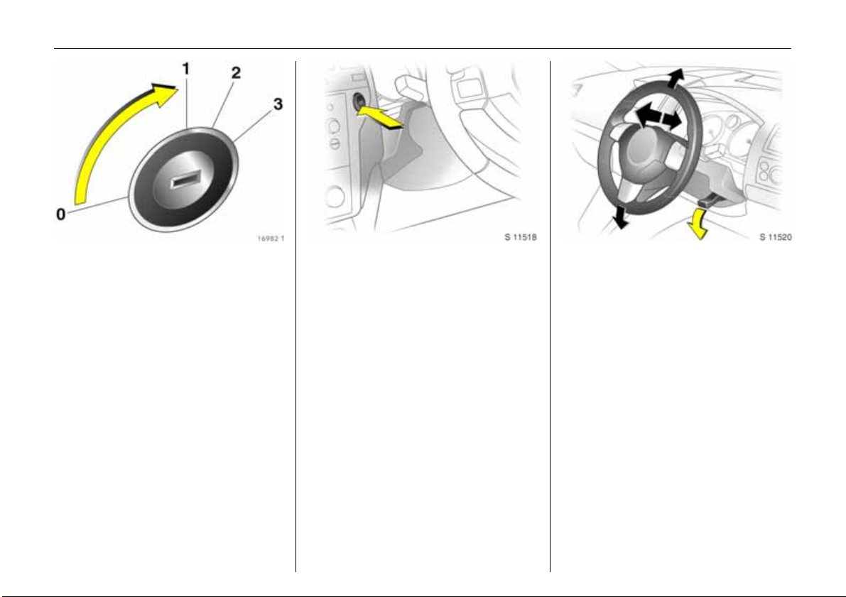
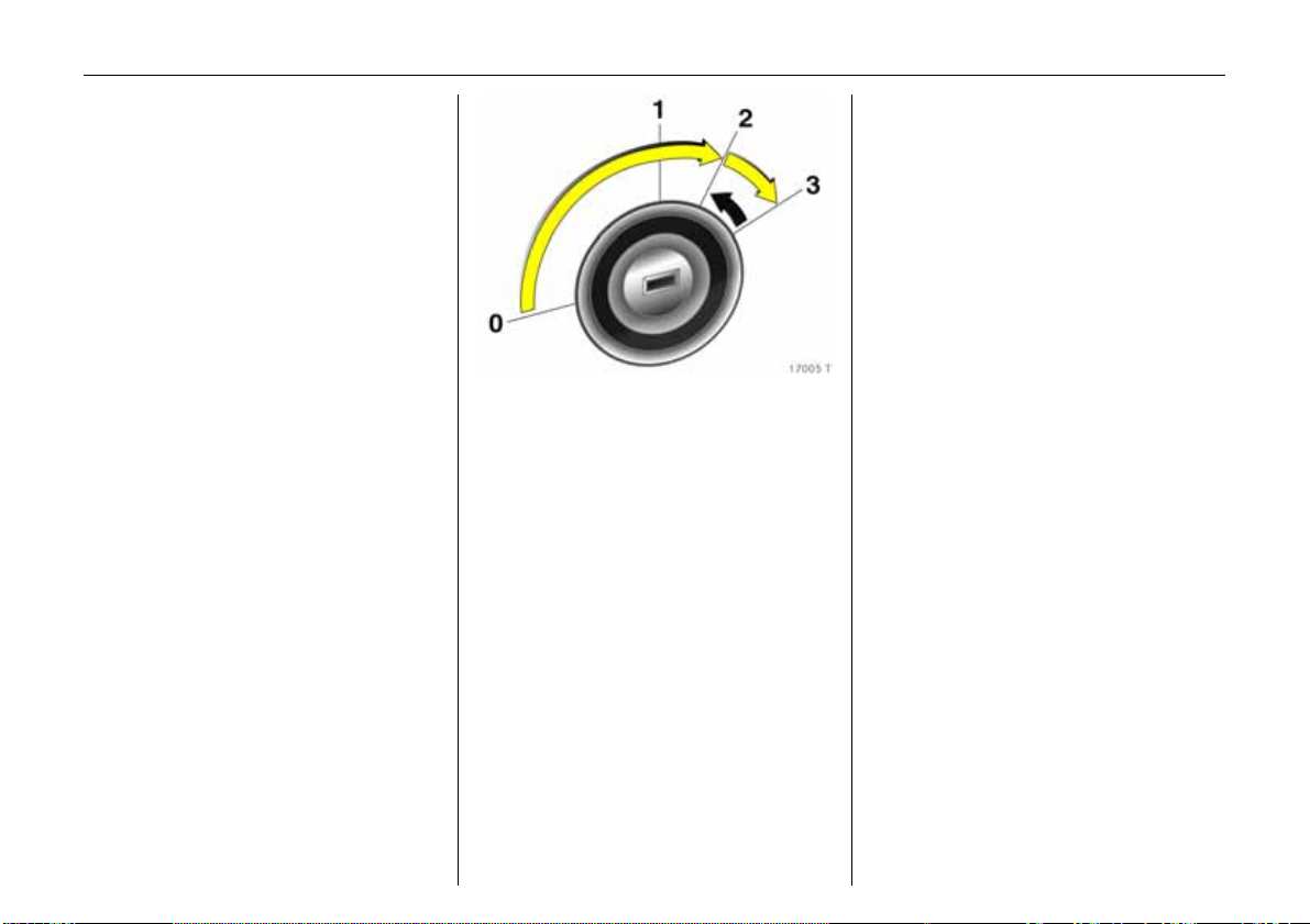
Steering column lock and
ignition:
Turn key to position 1.
To release lock, rotate steering
wh eel a litt le
Posit ions:
0 = Ignition off,
1 = Steering released, ig nition off
2= Ignition on,
Diesel engines: preheating
3= Starting
6 Start – page 16,
Electronic immobiliser – page 30,
Parking the vehicle – page 18.
Steering column lock and
ignition on vehicles with
Open&Start system
3:
Ensure electronic key is in the
vehicle interior reception
area and press t he Start/Stop
button
Release steering column lock by
moving steering wheel slightly
To start the vehicle, also operate brake or
clutch p edal.
To lock the steering wheel, switch ignition
off by pressing the Start/Stop button, open
driver’s door and engage steering wheel.
Do not allow vehicle to move whilst doing
this.
6 Start – page 17,
Electronic immobiliser – pa ge 30,
Parking the vehicle – page 18.
Steering wheel adjustment:
Swivel lever down,
adjust height and distance,
swivel lever up,
engage
Do not adjust steering wheel unless vehicle
is stationary and steering column lock has
be en re leas ed .
6 Airb ag system – page 69.
Page 14
10 In Brief
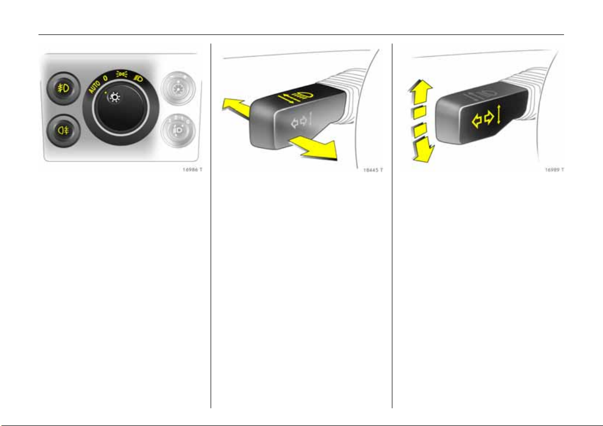
Turn light switc h:
7 =Off
8 = Parking lights
9 = Dipped beam or
main beam
AUTO = Automatic dipped
beam activation
3
Press button:
> = Front fog lights 3
r = Fog tail light
6 Lighting – page 105,
Headlight control indicator – page18.
He adl igh t fla s h, main beam an d
dipped beam:
Headlight
fla sh
=Pull stalk
towards
steering wheel
Ma in beam = S talk f orward s
Dipped beam = Stalk forwards
again or to the
steering wheel
6 Dipped beam, headlight flash –
page 105.
Switch on turn signals:
To the right = Stalk up
To the left = Stalk down
6 Turn signals – page 106.
Page 15
11In Brief
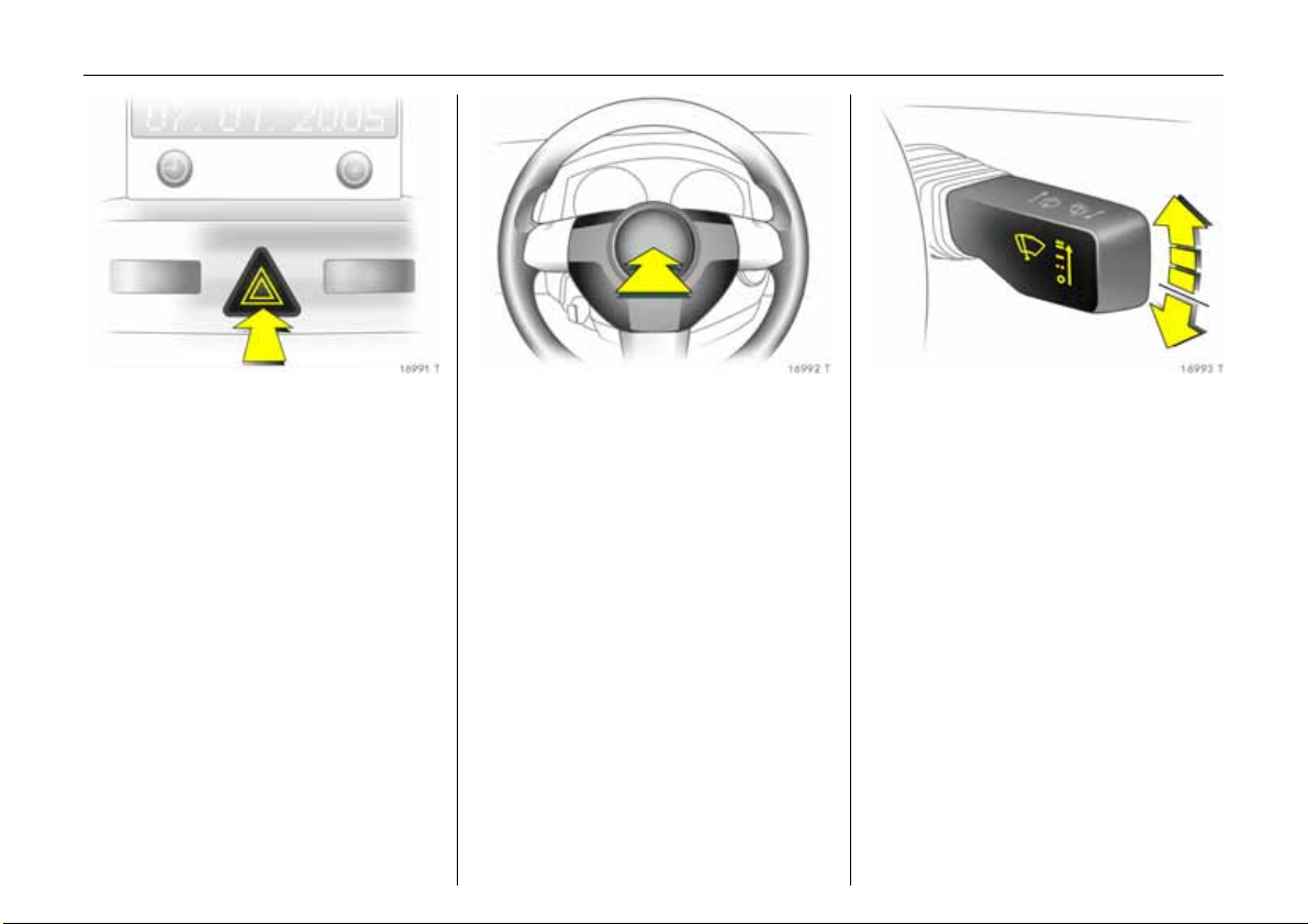
Hazard warning lights:
On = Press ¨
Off = Press
6 Hazard warning lights – page 107.
¨ again
Activate horn:
j Press in centre of steering
wheel
6 Airbag system – page 69,
Remote control on the steering wheel 3 –
page 112.
Windscreen wiper:
Move stalk up gently
§ =Off
$ = timed interval wipe
% =Slow
& =Fast
Press stalk down from position §:
Single swipe.
6 Windscreen wiper – page 102,
Adjustable wipe interval 3 – page 103,
Further information – pages 197, 206.
Page 16
12 In Brief
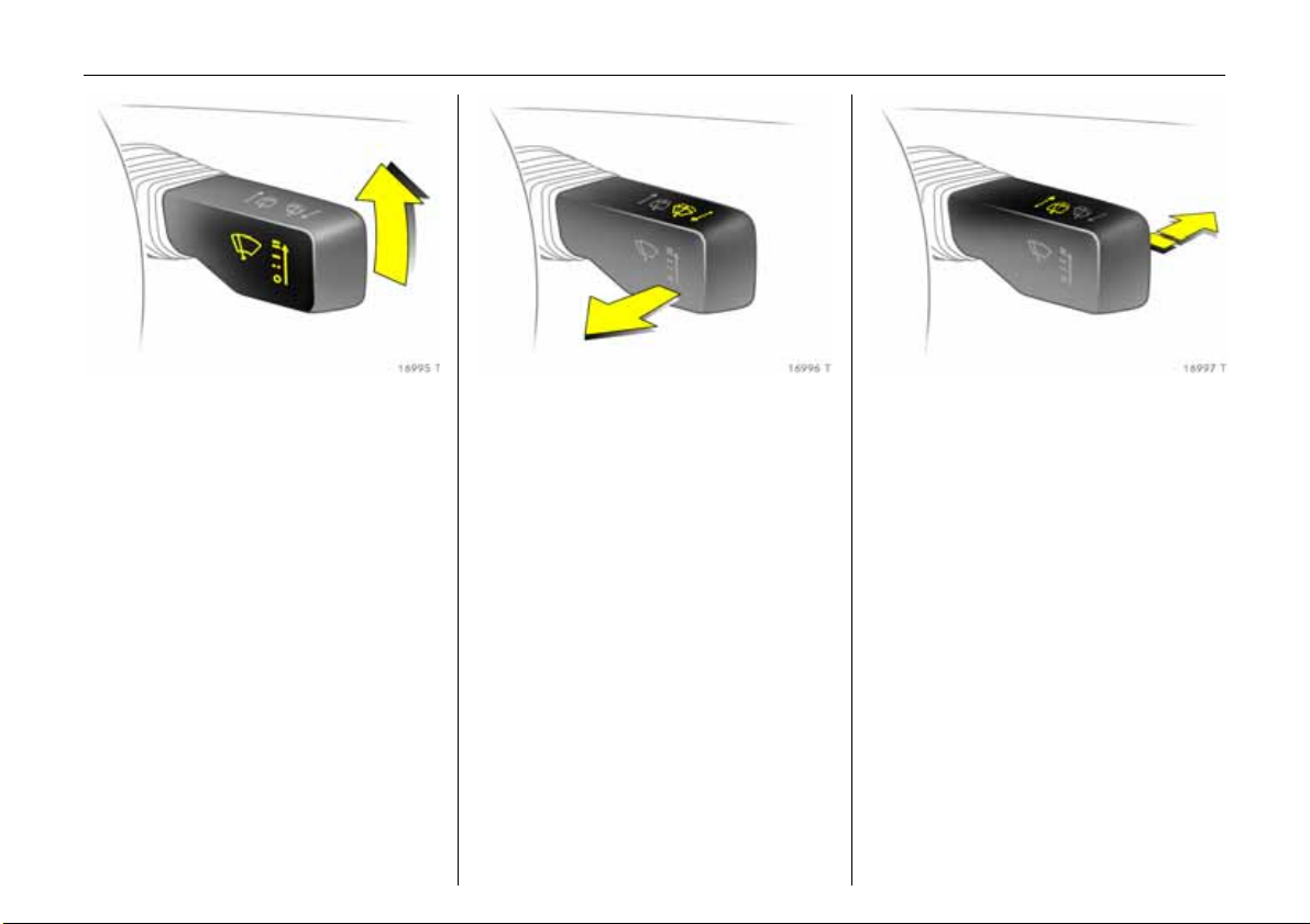
Automatic wiping with rain
sensor 3:
Move stalk up gently
$ = Automatic wiping with
rain sensor
§ =Off
6 Windscreen wiper – page 102,
Further information – pages 197, 206.
Operating windscreen and
headlight wash systems 3:
Pull stalk towards steering
wheel
6 Windscreen wa sh system and headlight
wash system – page103,
Further information – pages 197, 207.
Activate rear window wiper and
wash system:
Wiper on = Stalk forwards
Wiper off = Stalk forwards
again
Washing = Push the stalk
forw ards an d
then hold
6 Rear window wiper and wash system –
page 104,
Further information– p ages 197, 206.
Page 17
13In Brief
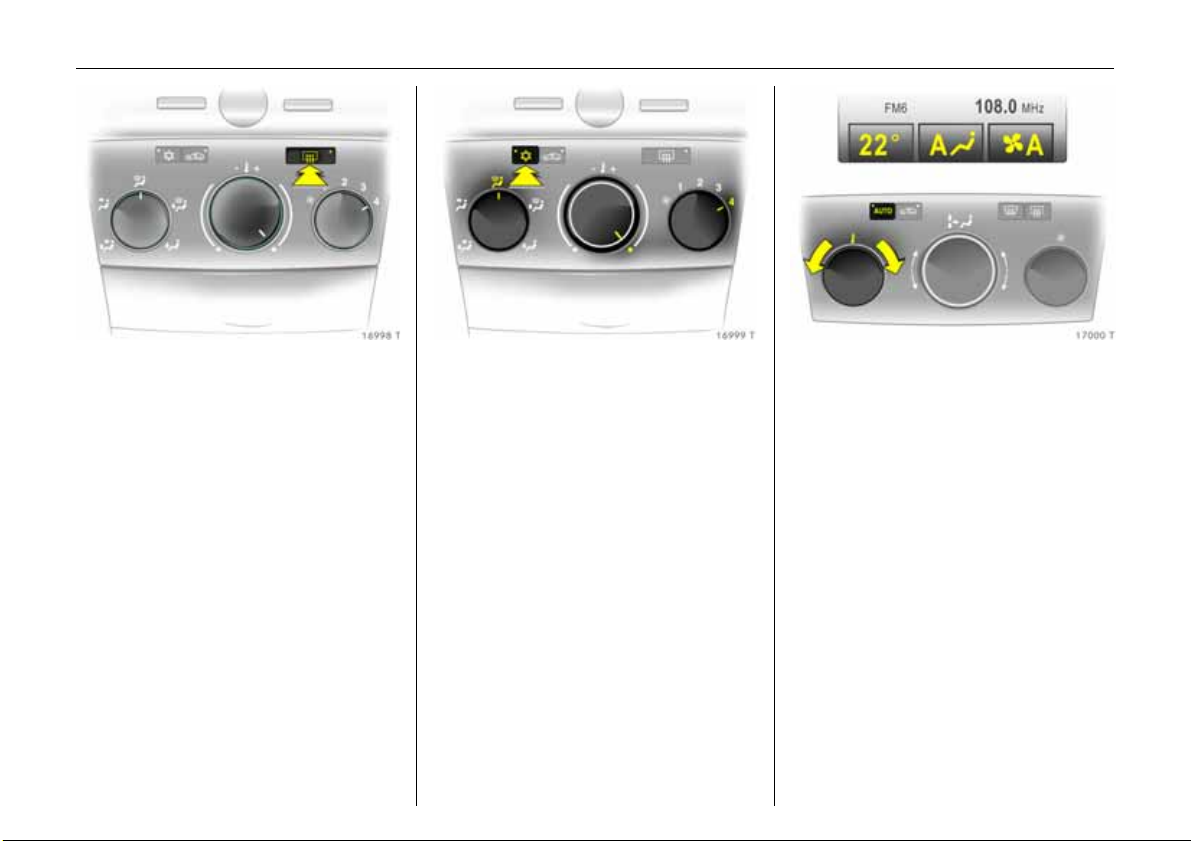
Heated rear window,
heated exterior mirrors:
On = Press Ü
Off = Press Ü again
6 Climate control – page 114,
heated rear window – page 116.
Clearing fogged or icy windows:
Air distribution on l,
Rotary knob for temperature
and air volume to the right;
Air conditioning system
3:
But ton n must also be pushed;
Automatic air conditioning
sys tem
Press buttons
3:
n and V ,
Move rotary knob for
temperature to the right,
air quantity to A;
Electronic Climate Control
(ECC)
3:
Press button
6 Electronic Climate C ontrol (ECC) 3 –
page 114.
V
Set automatic mode of
Electronic Climate Control
(ECC)
3:
Press AUTO button,
select temperature with rotary
knob,
open air vents
6 Electronic Climate Control (ECC) 3 –
see page 125.
Page 18
14 In Brief
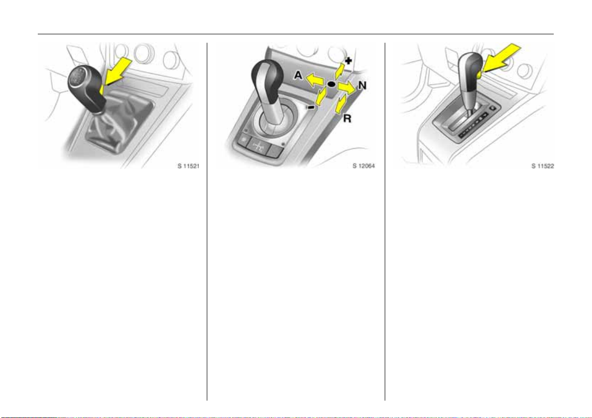
Manual transmission:
Reverse: with the vehicle stationary, wait
3 seconds after declutching and then pull
up the button on the selector lever and
engage the gear.
If the gear does not engage, set the lever in
neutral, release the clutch pedal and
depress again; then repeat gear selection.
Easy tron i c 3:
N = Idling
o =Driving position
+ = Higher gear
-=Lower gear
A/M = Switch between
Automatic and Manual
mode
R=Reverse gear (with
selector lever lock)
The selecto r lever mus t alway s be mo ved in
the appropriate direction as far as it will
go. Upon release, it automatically returns
to the centre position. Pay heed to the
gear/mode indicator in the transmission
display.
The footbrake must be depressed when
sta rtin g.
6 Ea sytronic 3 – page 131.
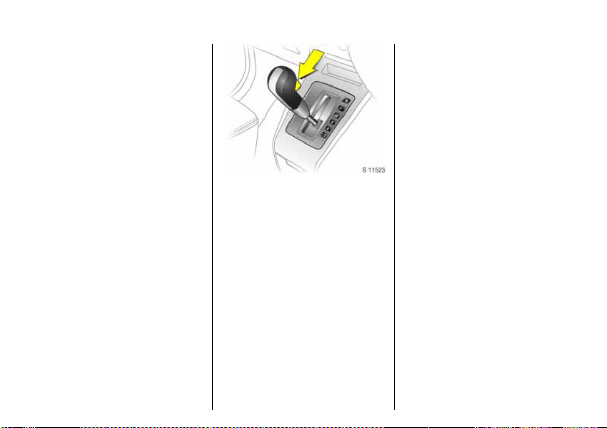
Automatic transmission 3:
P=Park position
R = Reverse gear
N=Neutral
(idling)
D = Automatic gear
selection
3 = 1st to 3rd gear
2 = 1st and 2nd gear
1=1st gear
P or N must be engaged when starting.
To leave P or N, switch on ignition, depress
footbrake and press button on selector
lever.
Page 19
15In Brief
Press button on selector lever to engage
P or R.
P only wh en th e vehicle is stationary,
apply handb rake first
R only when the veh icle is stationary
6 Automatic transmission 3 – page 136.
Press button on selector lever to e ngage
P or R.
P only when the vehicle is stationary,
apply handbrake first
R only when the vehicle is stationary
6 Automatic transmission 3 – pag e 136.
Automatic transmission
with ActiveSelect 3:
P=Park position
R=Reverse gear
N=Neutral
(idling)
D = Automatic gear
selection
Selector lever in D to the left:
Manual mode
+ = Higher gear
-=Lower gear
P or N mu st be engag ed w hen starting.
To le ave P or N, switch on ignition, depress
footbrake and press button on selector
lever.
Page 20
16 In Brief
Before starting-off, check:
z Tyre pressure and tyre condition –
seepages 159, 220.
z Engine oil level and fluid levels in engine
compartment – see pages 202 to 207.
z All windows, mirrors, exterior lighting
and num ber p la tes are fre e fro m dirt,
snow and ice and are operational.
z No objects are placed in front of the rear
wind ow, on th e ins trument pan el or in
the area in which the airbags inflate.
z Seats, seat belts and mirrors are
correctly adjusted.
z Brake op eration .
Start engine:
Operate clutch and brake,
automatic transmission
3
to P or N,
Easy tron i c
3: operate brake,
do not accelerate,
Petrol engine: turn key to 3;
Diesel engine: turn key to 2,
when control indicator
! goes
off1), turn key to 3;
Release key when engine is
runn ing
Before restarting or switching off
the engine, turn key back to 0 .
To switch on the ignition, only turn the key
to 2.
6 Electronic immobiliser – pa ge 30,
Diesel fuel system – page 203.
1)
Preheating system only switches on at low
outside temperatures.
Page 21
To switch on the ignition, do not press the
brake or clutch pedal and only press the
button briefly.
Do not start unless vehicle is stationary.
6 Open&Start system 3 – page 33,
Electronic imm obiliser – page 30,
Diesel f uel system – p age 203.
17In Brief
Start en gin e,
Open&Start system 3 :
Electronic key must be within
reception range of the interior,
Operate clutch or brake,
Automatic transmission
N, Easytronic
3: Operate brake,
3 in P or
do not accelerate,
Petrol engine: Press button;
Diesel engine: Briefly press
button, when control
indicator
! go es of f
1)
, press
button again for 1 second;
release button when engine is
running
Press button again to repeat the starting
procedure or switch off the engine.
1)
Preheating sy stem on ly sw itches on at low
outside temperatures.
Release handbrake:
Raise handle slightly, press
release button, lower handle all
the way
6 Handbrake – page 158.
Page 22
18 In Brief
Parking the vehicle:
apply handbrake firmly,
switch ignition off,
lock steering wheel,
lock vehicle
To lock, press button p on the remote
control or in the case of the Open&Start
system 3, touch the sensor in one of the
front door handles.
With Open&Start sy stem 3 , the d riv er’s
door must be open ed to lock th e ste erin g
wheel.
To activate the Vauxhall alarm system 3,
press button p or with Open&Start
sy ste m 3, touch sensor in one of the front
door handles. To activate the anti-theft
locking system 3, press button p twice.
6 For more information – page 30,
Open&Start system – page 33,
Radio remote control – pag e 32,
Central lock ing – page 37,
Vauxhall alarm system 3 – page 42,
Vehicle decommissioning – page 209.
Advice when parking:
z Do not park the vehicle on an easily
ignitab le sur fa ce. The high tem peratu re
of the exhaust system could ignite the
surfa ce .
z Always apply the handbrake firmly.
Apply the handbrake as firmly as
possible on uphill or downhill slopes.
To reduce operating forces, depress
foot b rake at the same time.
z Close window.
z Before switching off ignition: with
manual transmission, engage first
or reverse ge ar; with automatic
transmission 3, selector lever in P;
with Easytronic 3 engage first or
reverse gear (note gear indicator –
see pages 131, 136).
Page 23

19In Brief
z In vehicles with automatic
tr an s m i s si on 3 the ke y ca n on l y b e
removed with the selector lever in
position P. With the Open&Start
sys tem 3 "P" flashes in the transmission
displa y fo r se vera l se conds if P ha s no t
been selected or the handbrake has not
been applied.
z On vehicles with Easytronic 3 control
in d i ca to r R flashes for a few seconds
after the ignition is switched off if the
handbrake has not been applied –
seepage84.
z With the Open&Start system 3 the
engine can only be switched off when
th e ve hic le is sta tion ar y.
z Turn steering wheel until lock is felt to
engage (anti-theft protection),
removing ignition key beforehand.
With Open&Start system 3 switch off
ignition and open driver’s door.
z The engine cooling fans ma y run after
the engine has been switched off –
seepage201.
6 Further information –
seepages 207, 209.
That was the most important
information in brief for your first
drive in your vehicle.
The other pages of this chapter
cont ain a summary of the
noteworthy function s of you r
vehicle.
The remaining chapters of the
Owner’s Manual con tain
important information on
operation, safety and
maintenance as well as a
complete index.
Page 24
20 In Brief
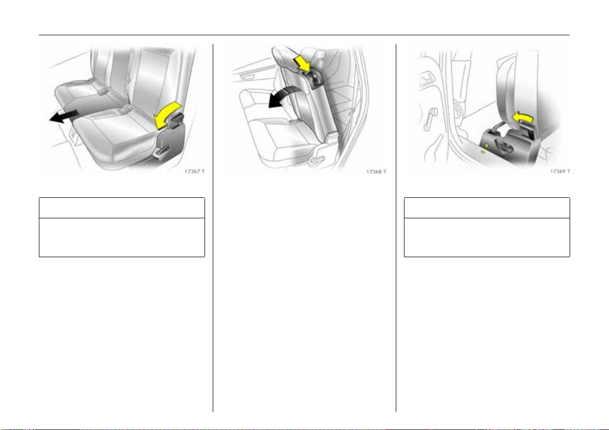
Seats in second row
9 Warning
When the row of seats or the backrests
are being adjusted, keep hands away
from the hinge a rea - risk of injury.
Moving seats
Push release handle on right or left hand
side of seat bench forwards and move seat
row forwards or backwards. Release
handle and allow seat row to lock into
position.
Adjust backrests of outboard s eats
Push down release lever on outboard side
of backrest, b ackrest angle can be
adjusted in two places towards the rear.
Release handle and latch backrest into
position.
The backrest engages in several positions.
The seat must not be occupied whilst the
vehicle is m oving if the seat is in the vertical
position or tilted forwards.
The outboard seat backrests can be tilted
forwards until they are flat in order to make
it easier to enter and exit the vehicle. Push
release lever down and tilt backrest
fo rw a rd .
To move the backrest upright or change
the position, push release lever down and
adjust backrest. Release handle and
engage back rest.
Seats in third row
9 Warning
When the seats are being moved upright
or folded in, keep hands away from hinge
area - risk of injury.
Mo ve se ats upright out of vehicle
floor
Remove floor covering 3.
Remo ving luggag e c om partment cover 3 –
see page 57.
Before moving the seats upright, slide seat
bench of second row of seats forwards by
pushing forward the lever at the right or
left-hand side of the seat b ench. The tip of
the arrow at the seat bench m ust be in
front of the square mark. Slide front seats
forwards a little if necessary.
Page 25
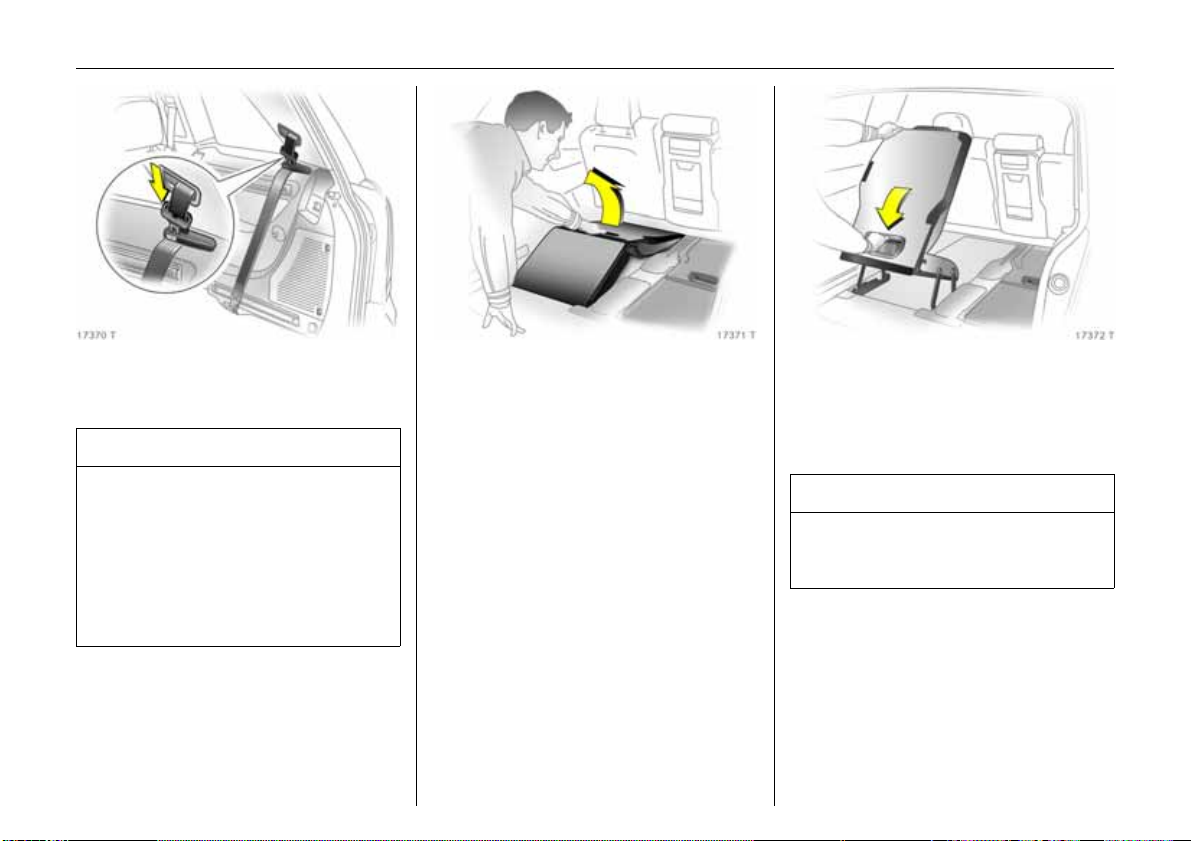
21In Brief
The sea t belts must be routed through the
belt holder as shown in the illustration. The
latch plates must be inse rted in the ho lder.
9 Warning
In the version with FlexOrganizer 3 – see
page 60, the belts must be suspended in
the right and left seat belt eyes on the
floor of the vehicle without twisting – see
illustration ab ove and page 67, Fig.
1742 0 T.
All components must be removed from
the rails 3 in the luggage compartment.
From luggage compartm ent, use one hand
to lift seat by the handle, swivel back and
move upright u ntil it a udibly engag es. Use
other hand to support top of backrest, see
Fig. 17372 T.
Lift up cover in floor between the seats and
swivel belt buckles upwards – see page 22,
Fig. 17374 T.
Remove latch plate and seat belt from seat
belt holder.
9 Warning
The belt must not be routed through the
belt holder when the seat belt is being
worn.
Move seat bench in second row of seats to
required position a nd engage by pushing
lever on right or left-hand side of seat
bench forwards – see page 20,
Fig. 17367 T.
Fit luggage compartment cover 3 by
fitting behind the third row of seats –
see page 57.
Page 26
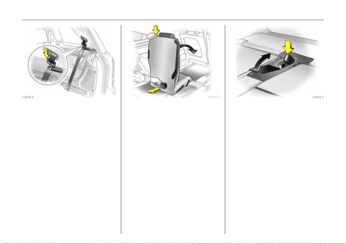
22 In Brief
Fold se ats into floor of veh icle
Remo ving luggage com partment c over 3 –
see page 57.
Before folding in the seat, slide seat bench
in se cond row of seats forwards by pushing
forward lever on right or left-hand side of
seat bench – see page 20, Fig. 17369 T.
The tip of the arrow on the seat bench must
be in front of the square mark. Slide front
seats forwards a little if necessary.
Pu sh down head restraints of seats in third
row – releasing spring catches by pressing.
Guide seat belts through belt holder as
shown in illustration and insert latch plates
into holder.
From lugga ge com partment, press button
at top of seat backrest and swivel backrest
forward. Raise seat by handle at rear and
swivel backrest further forwards until seat
is lowered into vehicle floor.
Hold seat by handle during the entire
swivelling procedure.
Push b elt buckles into recess in floor a nd
close cover.
Move seat bench in second row of seats to
required position a nd engage by pushing
lever on right or left-hand side of seat
bench forwards – see page 20,
Fig. 17367 T.
Fit luggage compartment cover 3 behind
second row of seats – see page 57.
Insert floor cover 3.
Th e compon en ts of the rails 3 and the
FlexOrganizer 3 – se e page 60, must only
be used with the seats in the third row of
seats folded in and the seat belts
unhooked – see page 67, Fig. 17420 T.
Attach rele ased belt hooks to magnets of
bracket – see page 67, Fig. 17399 T.
Page 27
23In Brief
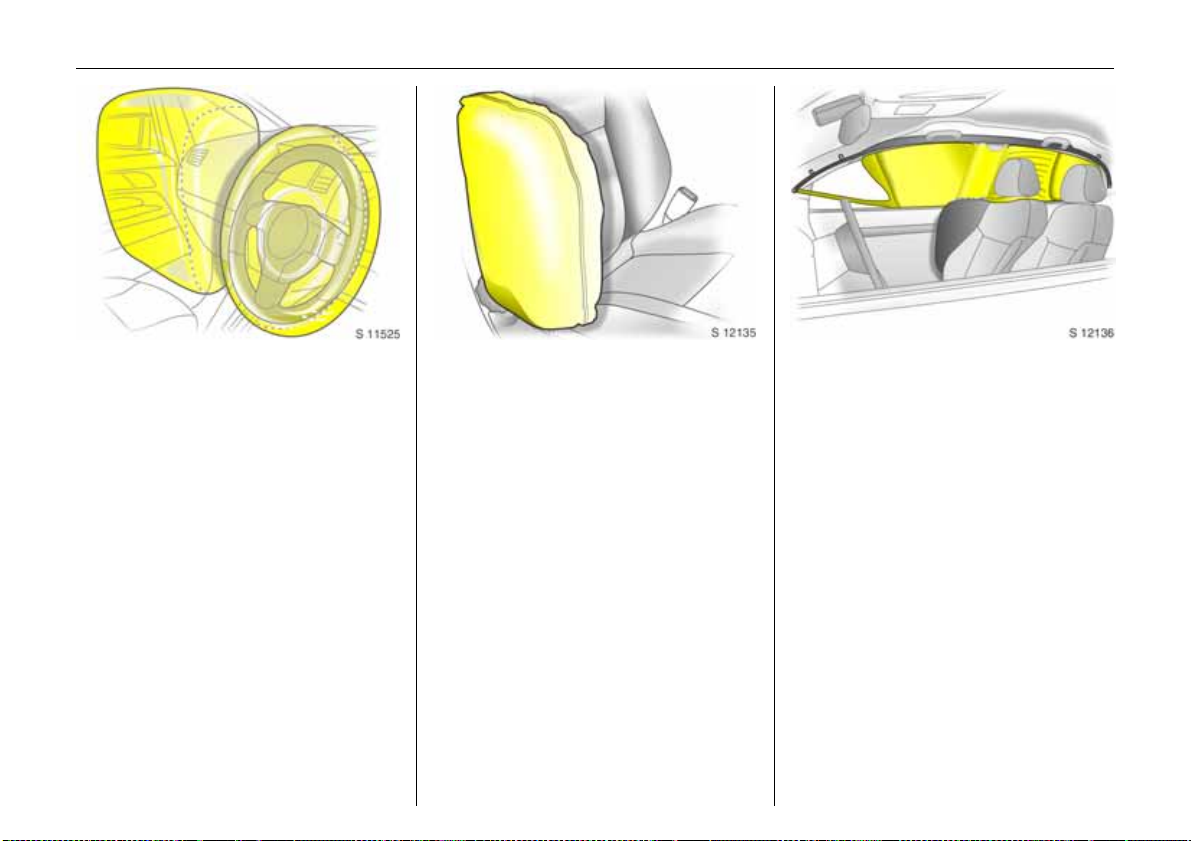
Airbag system
The airbag system consists of a number of
individual systems.
Front airbag system
The front airbag system is triggered in
the event of a serious accident involving
a fro ntal im pact and forms s afety cush ions
for the driver and front passenger.
The forward movement of the driver and
front passenger is checked and the risk of
injuries to the upper body a nd head
thereby substantially reduced.
Side airbag system 3
The side airbag is triggered in the event of
a side-on collision to form a safety cushion
for the driver or front passenger in the
respective door area. This substantially
reduces the risk of injury to the upper body
and pelvis.
Curtain airbag system 3
The curtain airbag system triggers in case
of a side-on collision and provides a safety
barrier in the head area on the respective
side of the vehicle. This reduces the risk of
injury to the head considerably in case of a
side-on collision.
6 Airb ag system – page 69.
Page 28
24 In Brief
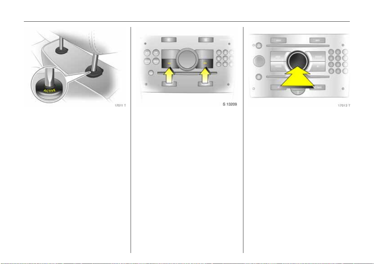
Active head restraints 3 on front
seats
In the event of a rear-end impa ct, the
active head restraints tilt forwards slightly.
Th e head is more effectiv ely suppor ted by
the head restraint and the risk of injuries
caused by whiplash in the neck area is
reduced.
Active head restraints are identified by the
lettering ACTIVE on the head restraint
guide sleeves.
6 Head restraints – page 51.
Operating menus in the
information display 3
Menu options are selected via menus
and using the arrow buttons or the
multi-function knob of the Infotainment
sy ste m 3 or the buttons 3 on the steering
wheel. Therespective menu options are
shown on the display.
Selection using the arrow buttons 3: Press
the arrow buttons to the left or right.
Selection using multi-function knob 3:
rotate and press multi-function knob.
To exit a menu, turn the multi-function
knob left or right to Return or Main and
select.
Page 29
Ü Board Computer 19,5° 19:36
BC 1 All values
BC 2
Timer
Tyres
1111
257.0 miles
Ø40mph
7.0 ga ls
8888
Ø 31 . 0 mp g
25In Brief
Coolant level
check
OK
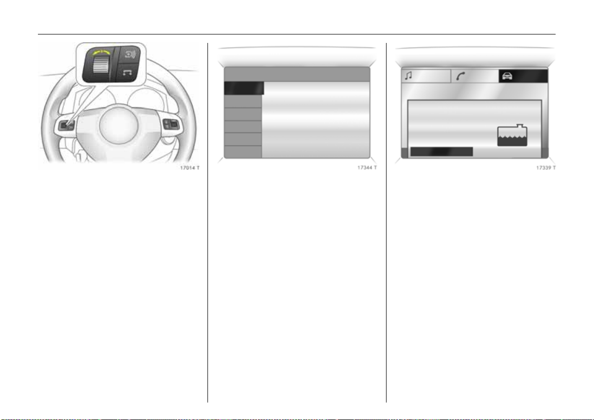
Selection with left adjuster wheel on
steering wheel 3: turn adjuster wheel and
press.
6 Information display – page 89
Trip compu ter 3
The trip computers provide information on
driving data, which is continually recorded
and evaluated electronically.
Functions:
z Range
z Instantaneous consumption
z Distance
z Average speed
z Effective consumption
z Average consumption
z Stop watch
z Tyre pressure 3
6 Trip computer 3 – pages 93, 98.
Check control 3
The check control software monitors
z Fluid le vels
z Tyre pressure 3
z Remote control battery
z Vauxhall alarm system 3
z Important exterior lighting, including
cables and fuses.
6 Check control 3 – page 101.
Page 30
26 In Brief
Remote control on steering
wheel 3
The functions of the Infotainment system 3
and the information display can be
operated with the remote control on
the steering wheel.
Further information is available in
the I nfotainment system operating
instructions.
6 Remote control on steering wheel 3 –
page 112,
Infotainment system – page 113.
Twin Audio 3
Twin Audio p rov id es rear seat occupants
with the opportunity to listen to a different
audio source than the one selected by the
driver on the Infotainment system.
Only an audio source that is not currently
active on the radio system can be
controlled using Twin Audio.
Two headphone connections are a vailable,
with separate volume controls.
Further information is av ailable in the
In fotain me nt sy st e m ope ra ting
instructions.
6 Twin Audio 3 – page 112.
Open&Start system with
electronic key and radio
remote control
The Open&Start system allows the vehicle
to be locked and unlocked, including
mechanical anti-theft locking system 3
and the Vauxhall ala rm system 3 withou t a
mechanical key and the engine to be
started and stopped using a S tart/Stop
button. All the driver has to do is carry the
electronic key around with him.
6 Open&Start system 3 – page 33.
3
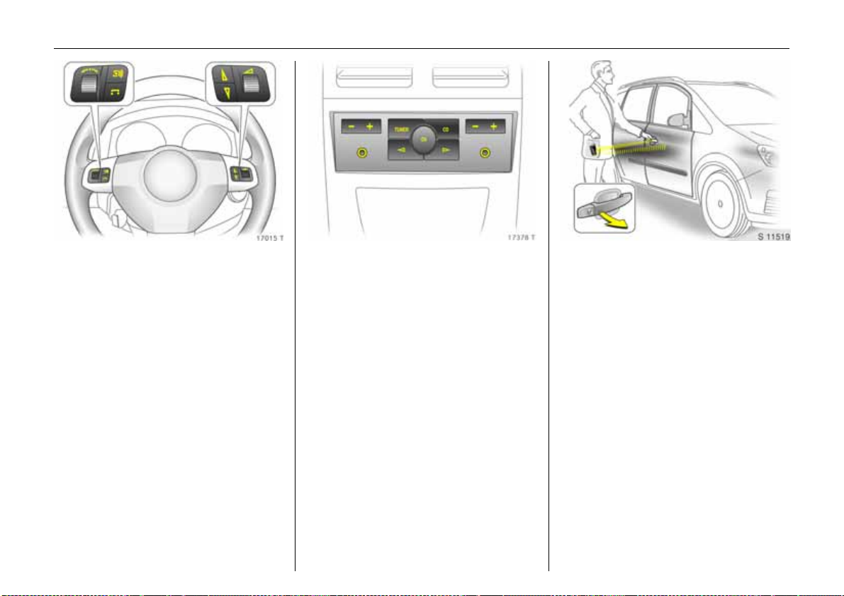
Page 31

27In Brief
Parking distance sensors 3
When reverse gear is selected, the parking
distance sensors switch on automatically.
The parking distance sensors can also be
enabled m anually at a speed of less than
15 mph (25 km/h) using the r button on
the instrument panel.
If the vehicle approaches an obstacle at
the front or the rear, a series of acoustic
signals is heard in the vehicle interior.
The interval between the signals becomes
shorter as the obstacle becomes closer.
The signal is continuous if the distance is
less than 30 cm.
6 Parking distance sensors 3 – page 152.
Sport mode 3
To activate
Pre ss SPORT button.
SPORT mode is used to change
damping 3 , stee ring 3, throttle
application and the shift point for
Eas ytro nic 3 and automatic
transmission 3 whilst driving.
Damping and steering become more direct
and provide better contact with the road
surface. The e ngine reacts more quickly to
accelerator movements.
With Easytronic 3 and automatic
transmission 3, the shift times are
shortened and shifting tak es place at
higher revs (not with cruise control
enable d 3).
6 Sp ort m ode 3 – page 150.
FlexOrganizer 3
The side walls contain retaining strips,
where various components can be
attached to divide the luggage
compa rtment o r fasten loads.
The sy st e m consists of
z adapters
z variable partition net
z mesh pockets for the side walls
z hooks in the luggage compartme nt
6 Fle xO rg aniz er 3 – pag e 60.
Page 32

28 In Brief
Ü Board Computer
BC 1
BC 2
Timer
Tyres
Tyre pressure loss monitoring
system (DDS = Deflation
Detection System)
The Deflation Detection System
continuously monitors the speed of all
wheels whilst driving. If a tyre loses
pressure, it becomes smaller and therefore
rotates more quickly than the other wheels.
If the system detects a difference in speed,
the control indicator w illuminates in red.
3
After a tyre pressure correction or after a
tyre or wheel change, the system must be
initialised by pressing the DDS button.
6 Tyr e p ressure loss monitor ing sy ste m 3 –
page 154.
Tyre Pressure Monitoring
System 3
The Tyre Pressure Monitoring System
continually checks the pres sure and spe ed
of all four wheels whilst driving.
A pressure sensor is installed in each wheel.
The inflation pressures of the individual
wheels are transmitted to a controller,
where they are compared.
The current tyre pressures can be
displayed on the Graphical Information
Display or the Colour Information
Display 3.
Deviating tyre pressures are displayed in
the form of messages on the information
display whilst driving.
6 Tyre Pressure Monitoring System 3 –
page 155.
Page 33

29In Brief
Motorwa y ligh ti ng
At higher speeds and continuous straight
ahead travel, the dipped beam
automatically raises slightly, thereby
increasing headlight range.
Adaptiv e Forward Lighting 3 – page 108.
Adaptive Forward Lighting
(AFL) 3
AFL im proves lighting in curves (curve
lighting) on vehicles with Bi-Xenon
headlight system.
Curve lighting
The Xenon light beam pivots based on
steering wheel position and speed
(from approx. 6 mph (10 km/h)).
Page 34

30 Locks, Doors, Windows
Locks, Doors,
Windows
Re placem ent keys ... ......... ......... ......... . 3 0
Lock cylinders . ..... .... ......... ......... ......... . 3 0
Ca r Pass... .... .... .............. .... ..... ............. . 3 0
Key with foldaway key section 3...... . 30
Electronic immobiliser....... ..... ............. . 3 0
Store personal vehicle settings in the
vehicle ke y 3 ..... .... ..... ............. .... ..... . 31
Radio frequency remote control 3
with mechanical key .. ............. .... ..... . 32
Open&Start system 3 ... .... ......... .... ..... . 3 3
Central locking system . .... ......... ......... . 37
Fault when lockin g o r unlocking........ . 40
Luggage compartment.... ..... .... .......... 41
Vauxhall alarm system 3. ..... .... .......... 42
Child s afe ty locks ..... ..... .... ......... ......... . 45
Exterior mirrors..... ......... ......... ........ ...... 45
Interior mirror ....... ......... ......... ........ ...... 46
Ele ctric win dows 3 ........ .... ..... ............. . 46
Sunblind on panoramic roof 3 ..... ..... . 48
Replacement keys
The key number is specified in the vehicle
documents and in the Car Pass 3.
The key is a constituent of the electronic
immobiliser. Ordering keys fr om a Vau xhall
Authorised Repairer guarantees problemfree operation of the electronic
immobiliser.
When electronic keys of the Open&Start
system are bein g replaced , all keys mu st be
handed to the dealer for programming.
Keep the spare key in a safe plac e.
Locks – see page 197,
Open&Start system, electronic keys –
see page 33.
Lock cylinders
Des igned to fre e-wh e el if th ey are
forcefully rotated without the correct key or
if the correct key is not fully inserted.
To reset, turn cylinder with the correct key
until its slot is vertical, remove key and then
re-insert it. If the cylinder still free-wheels,
turn the key through 180° and repeat
op er at io n .
Car Pass
The Car Pass contains all of the vehicle’s
data an d sho uld th erefo re not be k ept in
the vehicle.
Have your Car Pass to hand when
co nsulti ng a V aux ha ll Authorised Re pairer.
Key with foldaway key section 3
Press button to extend. Press button to
retract and key section engages audibly.
Electronic immobiliser
Page 35

31Locks, D oors, Windows
Th e sys tem check s w heth er th e veh icle is
allowed to be started with the mechanical
key or electronic key of the Open&Start
system 3 that is being used. If the key is
recognised as "authorised" the vehicle can
be started. The checking tak es place via a
transponder in the key.
The electronic immobiliser activates itself
automatically after the key has been
removed from the ignition or, with the
Open&Start system 3, when the engine is
switched off by pressing the Start/Stop
button.
Th e code number o f th e e lectronic
immobiliser is given in the Car Pass.
Con trol ind ic ator for immo bili ser A
Control indica tor A illuminates briefly
wh en the ig nitio n is sw itche d on .
If the control indicator flashes when the
ignition is on, there is a fault in the system;
the engine cannot be started. Switch off
the ignition and then repeat the start
attempt.
If the control indicator A continues
flashing, attempt to start the engine using
the spare key a nd seek the assistance of a
workshop.
If control indicator A illuminates after the
engine is started, there is a fault in the
engine electronics or transmission
ele ctron ics 3 (see page s 135, 140, 147) or
there is water in the diesel fuel filter 3 – see
page 203.
Note
The immobiliser does not lock the doors.
Therefore, after leaving the vehicle always
lock it and switch on the Vauxhall alarm
system 3 – see pages 38, 42.
Store person al vehicle settings
in the vehicle key 3
The last settings selected
z for the Electronic Climate Control
(ECC) 3
z information display 3
z Infotain m e nt system 3
z instrument illumination
are stored automatically depending on the
vehicle key used.
Different settings are stored for each
vehicle key. Use of a vehicle key will
activate the settings associated with it.
Each time the vehicle is locked, the settings
are saved again.
Page 36

32 Locks, Doors, Windows
Radio frequency remote
control 3 with mechanical key
Depending on the equipment level of your
vehic le, one of the remote controls shown
on this p age will be used.
Radio frequency remote control in version
with Open&Start system 3 – see page 34.
The remote control is integrated in the key.
Us ed to op erate :
z Central locking system,
z Mechanical anti-theft locking system 3,
z Vauxhall alarm system 3.
The windows of vehicles with electric
windows in all doors 3 can also be opened
or closed u s ing the r e mote c ontr ol – see
page 46.
The remote control has a range of approx.
5 metres. This range can be affected by
outside influences. Aim the remote control
at th e v ehicle to op erate.
Handle the remote control with care,
protect it from moisture and high
temperatures and avoid unnecessary
op er at io n .
Function check by illumination of hazard
warning lights.
Central locking system, mechanical
anti-theft locking system 3
see page 37.
Vauxhall alarm system 3
see page 42.
Electric windows 3
see page 46.
Fault
If the central locking system cannot be
operated with the remote control, itmay
be due to the following:
z The range of the remote control has
been exceeded.
z Remote control battery voltage is too
low. Battery replacement – see next
page.
z Frequent, repeated operation of the
remote control outside the reception
rang e of the vehicle (e.g. too far from
vehicle, remote control is then no longer
recognised). Remote control
synchronisation – se e next page.
z Overloading the c entral locking by
operating at frequent intervals, the
power supply is interrupted for a short
time.
z Interference from higher-power radio
wa ves fro m othe r source s.
To rectify the cause of the fault, we
recommend that you seek the assistance of
a workshop.
Open d riv er’s door with key – see page 40.
Page 37

33Locks, D oors, Windows
Remote control battery re placement
Replace the battery as soon as the range
of the remote control begins to shrink.
Key with foldaway key section
Extend k ey – see page 30. Open remote
control. Replace battery - battery type –
see page 223 – noting installation position.
Close remote control.
Make sure that you dispose of old batteries
in accordance with environmenta l
protection regulations.
Key with fixed key section
Have the battery replaced by a workshop.
In the event of a malfunction or when
the battery h as been replac ed,
synchronis e the rem ote control
After rep lacing th e battery, u nlock the door
with the key in the lock. The remote control
will be synchronised whe n you switch on
the ignition.
Open&Start system 3
The Open&Start system allows the vehicle
to be locked and unlocked, including the
mechanical a nti-theft locking system 3
and the Vauxhall alarm system 3, and the
engine to b e started and stopped without
a mechanical key. All the driver has to do is
keep the key to hand.
The windows of vehicles with electric
windows in all doors 3 c an als o be opened
or closed from outside using the remote
control of the electronic key – see page 40.
The electronic key must be within the
external reception range about 1 metre
from the vehicle in order to lock and unlock
the vehicle.
If the electronic key is recognized as
"authorised" the vehicle can be unlocked
by pulling a door handle or by operating
the button beneath the tailgate handle
and the doors and the tailgate can b e
opened.
Page 38

34 Locks, Doors, Windows
When the S tart/Stop button is pressed, the
system re-checks the authorisation. The
electronic key has to be recognised in the
interior in order to do this. After the key has
been authorised the ignition switches on.
At the same time, the electronic
immobiliser is s witched off and the electromechanical steering column lock is
deactivated . Pressing the Start/Stop button
again with the brake or clutch pedal
depressed or in P or N with automatic
transmission 3 starts the engine. Press
button for at least one second with the
vehicle stationary or hold down until the
engine starts.
If the brake or clutch pedal is depressed,
the engine can be started right away with
a single press on the Start/Stop button.
Releasing the Start/Stop button interrupts
the starting procedure.
The engine and the ignition are switched
off by p ressing the Start/Stop button again.
The vehicle must be stationary. The
immobiliser is activated at the same time.
If the ignition has been switched off and
the ve hicle is s tationary , the stee rin g
column lock activates automatically when
the driver’s door is opened or closed.
The electronic key must be within the
reception range of the interior to turn the
ignition on or off. We recommend that the
driver carries th e elec tronic ke y with him. If
the electronic key is not recognised, select
another key position.
Do not put the electronic key in the
luggage compartment or in front of the
information display.
The vehicle is locked from the outside with
the doors closed by touching the sensor
panel in the door handle of one of the front
doors. The electronic key must be within
the external reception range of
approximately one metre from the vehicle.
Th e Open&Start system 3 does not th e lock
the vehicle automatically if the electronic
key is outside the external reception range
of approximately one metre from the
vehicle.
Rad io fr equen cy remot e co nt ro l
The vehicle can be locked and unlocked by
conventional means using the remote
control with the buttons on the electronic
key.
In addition, the me chanical anti-theft
locking system and Vauxhall alarm system
can b e arm ed and disabled using the
remote control. The windows of vehicles
with electric windows in all doors 3 can
also be opened or closed from outside
using the remote control.
Page 39

35Locks, D oors, Windows
The remote control has a range of approx.
5 metres. This range can be affected by
outside influences. Aim the remote control
at the vehicle to operate.
Handle the remote control with care,
protect it from moisture and high
temperatures and avoid unnecessary
operation.
Function check by illumination of hazard
warning lights.
Cen tr al l oc kin g sy st em,
mec han ical an ti-t he ft lo cking
system 3
see page 37.
Vauxhall alarm system 3
see page 42.
Electric windows 3
see page 46.
Con trol ind ic a to r for Ope n& Start
system 0
If the control indicator flashes 0 with the
ignition switched on or with the engine
running an operating error has occurred,
e.g. the electr onic ke y is no longer w ithin
the reception range of the vehicle interior.
During the next starting procedure the
engine may not be able to be started. Press
Start/Stop key slightly longer to switch the
ignition off.
Flashing of the 0 can a lso b e an indication
of complete failure of the electronic key. In
this case operation is only possible using
the emergency facility – see next column.
InSP3 in the service display or an
appropriate m essage in the information 3
display indicates that the battery of the
electronic key needs replacing – see
page 36.
If the control indicator 0 is permanently
on, an error has occurred in the system.
Lock or unlock vehicle using the remote
control or the emergency key if necessary –
see page 37, or try using the spare key.
If 0 illuminates, this can also mean that
the steering column lock is still locked:
move steering wheel to and fro a little and
press Sta rt/Stop button again.
If th is 0 comes on when the vehicle is in
motion, th ere is a system erro r. Se ek the
assistance of a workshop immediately.
Emergency operation
If th e Op en&Start system or the electronic
key fails (control indicator 0 flashes or is
pe rmanen tly on) the driver’ s door ca n be
locked or unlocked with the emergency key
in the electronic k ey: press locking
mechanism on underside and re move cap
towards the front by applying g entle
Page 40

36 Locks, Doors, Windows
pressure to the cap. Push emergency key
towards the outside over the detent
position and re move.
Only the driver’s door can be locked and
unlock ed using the eme r gency key . Th e
entire vehicle is unlocked as described on
page 41.
The Vauxhall alarm system 3 may be
triggered when the vehicle is unlocked.
Switch ignition on to deactivate alarm and
release the steering column lock: hold
electronic key at marked position on the
steering column p anelling and press the
Start/Stop button. Repeat procedure if
necessary.
Hold electronic key at the marked location
to start the engine, depress brake peda l or
clutch p edal or in vehicles with automatic
transmission 3 depress brak e pedal a nd
se lect P or N, Then press Start/Stop button
again.
Press Start/Stop b utton for at least
2 seconds to switch the engine off. Lock all
doors except driver’s door as described on
page 41. Lock driv er’s door with
emergency key.
This option is intended for emergencies
only. Replace the battery in the electronic
key as quickly as p ossible or hav e the
system repaired. Seek the assistance of
aworkshop.
Replacing battery in electronic key
Replace battery immediately if the system
is no longer operating properly, or the
range of the remote control deteriorates.
The need for a battery change is
indicated by InSP3 in the S ervice Display or
in vehicles with check control 3 an
appropriate message appears on the
display – see page 101.
Page 41

37Locks, D oors, Windows
To repla ce the battery, press the locking
mechanism on the underside of the
electronic key and remove the cover
towards the front by applying gentle
pressure – see page 35, Fig. 17037 T. Push
off cover with emblem on the button side
towards the outside.
Replace battery, for battery type – see
page 223, pay attention to installation
position. Engage caps.
Radi o fre quency re mot e co nt ro l
synchronisation
The remote control synchronises itself
automatically during every starting
procedure.
Fault in Open&Start system or remote
co ntro l
If the central locking can not be ope rated or
the engine cannot be started, the cause
may be one of the following:
z Electronic key out of reception range, or
out of range of remote control,
z Remote control battery voltage is too
low. Battery replacement – see page 36,
z Frequent, repe ated op eration of the
remote control outside the reception
range (e.g. too far from vehicle, remote
control is then no longer recognised),
z Overloading the central locking by
operating at frequent intervals, the
power supply is interrupted for a short
time,
z Interference from higher-power radio
waves from other sources.
To rectify the cause of the fault, cha nge the
position of the electronic key or remote
control or replace the battery in the remote
control. If the fault persists, seek the
assistance of a workshop.
Emergency operation – see page 35.
Central locking system
For doors, boot lid/tailgate and tank flap.
To unlock:
Remote control with mechanical key
Press button q on remote control.
To open the door, pull the handle. Open
the luggage compartment by operating
the button beneath the tailgate handle.
Page 42

38 Locks, Doors, Windows
O p en&S tart sy s tem wit h ele ct r onic key 3
The electronic key must be outside of the
vehicle. The vehicle is unlocked by pulling a
door handle or by operating the button
beneath the tailgate handle.
– or –
Press button q of the elec tron ic ke y’s
remote control.
To lock
Close doors, lugga ge compartment and
tank flap.
Remote con trol with me chanic al key
Press button p on remote control.
Open&Start system with electronic key 3
Th e electronic k ey must b e ou tsid e of th e
vehicle. All doors and the luggage
compartment are locked by touching the
sensor in the door ha ndle of the driver’s or
front passeng er’s door
– or –
Press button p of th e electronic k ey’ s
remote control.
Mec h an ic al an ti -t he ft locki ng
sys tem 3
9 Wa rn ing
Do not use the system if there are people
in the vehicle! The doors cannot be
unlocked from inside.
Remote control with mechanical key
All doors must be closed. At the latest
15 se conds after lo cki n g, p ress b utton p
of the remote control ag ain.
Page 43

39Locks, D oors, Windows
Lock buttons on all doors are positioned
such that doors cannot be opened.
If the ignition was on, the driver’s door
mu s t be open ed and closed once s o that
the vehicle can be secured.
O p en&S tart sy s tem wit h ele ct r onic key 3
All doors must be c losed. The e le ctronic key
must be outside of the vehicle. No more
than 15 seconds after locking, touch the
sensor in the handle of the driver’s or front
passenger’s door ag ain
– or –
press button p of the electronic key’s
remote control again.
If the ignition was on, the driver’s door
mu s t be open ed and closed once s o that
the vehicle can be secured.
All doors are sec ured aga inst opening.
Central locking button for locking
and unlocking the doors from inside
th e veh icle
Pre ss bu tton m in the centre console: doors
are locked or unlocked.
The LED in the central locking b utton m
illuminates for around 2 minutes after
locking with the remote control.
If th e doo rs are locked from the insid e
during driving using the central locking
button, the LED m illuminates
permanently.
If the key is in the ignition 3, locking is only
possible if all doors are closed.
When the mechanical anti-theft locking
sy ste m 3 is active – see page 38, the doors
cannot b e unlocked with this button.
Note
z If the driver’s door is not closed properly,
the central locking system will not lock.
z To lock the doors from within (e.g. to
prevent unwanted entry from outside),
press central locking switch m in th e
centre console.
z After unlocking with the key in the lock 3
and opening the driver’s door, the entire
vehicle is unlocked.
z If the central locking system is locked, the
doors can also be unlocked by p ulling
the interior handle. This unlocks the
central locking system.
z Locked doors unlock themselves
automatically when an accident of
a certain severity occurs (for outside
assistance), and the hazard warning
lights come on. In the version with a
mechanical key, the key must also be in
the ignition.
z With the Open&Start system 3 the
vehicle cannot be unlocked within
2 seconds of locking. Within this time a
door handle can be pulled or the button
beneath the tailgate handle operated to
check whether the vehicle is locked.
z The Open&Start system 3 does not lock
the vehicle automatically if the electronic
key is outside the reception range of the
vehicle (more than 1 metre away from
the vehicle).
Page 44

40 Locks, Doors, Windows
z A spare key must not be present in the
vehicle with the Open&Start system 3
when the vehicle is being locked.
z The locking sensors in the door handles
mu st be ke pt cl e an for unre stricte d
functionality with the Open&Start
sys tem 3.
Operating the windows 3 from the
outside
9 Warning
Take c are whe n operat ing th e electric
windows. Risk of injury, particularly to
children.
Vehicle passengers must be informed
accordingly.
Keep a close watch on the windows w hen
closing them. Ensure that nothing
becomes trapped in them a s they move.
Dep ending on the v ehicle equipme n t 3,
the windows can be opened and closed
from the outside in v ehicles with powe r
windows in all doors.
Remote con trol with me chanic al key
Hold button q or p on the remote control
depressed until all windows have opened
or completely closed.
Open&Start system with electronic key 3
Hold down button q of remote control to
open. To close, hold down button p or
touch sens or in door handle for longer. The
electronic key must be recognised within
th e ex tern al recep tion ra ng e. It is advis able
for the driver to keep the electronic key to
hand.
Further information on windows –
see page 46.
Fault
z Overloading the c entral locking by
operating at frequent intervals, the
power supply is interrupted for a short
time,
z Defective fuse in fusebox –
see page 184.
To rectify the cause of the fault, seek the
assistance of a workshop.
Fault when locking or unlocking
Page 45

41Locks, D oors, Windows
Fa ul t in remo t e co ntro l or Open& Start
system 3
To unlock
Tu rn key or em erge nc y key with
Open&Start system 3 – see page 35,
forwards in driver’s door lock a s far as it will
go. Turn key back to a vertical position and
remove. The entire vehicle is unlocked
when the driver’s door is opened. The
vehicle is unlocked (not possible if antitheft locking system 3 enabled
beforehand). To deactivate the anti-theft
locking system 3 switch ignition on.
Emergency operation of the Open&Start
system 3 – see page 35.
To lock
Open front pas se n ger’s door, close d riv er’s
door, press central locking button m in
centre console. Central locking system
locks all doors. Close front passenger’s
door.
Malf unction in ce ntra l l ocking s yste m
To unlock
Tu rn key or em erge nc y key with
Open&Start system 3 – see page 35,
forwards in driver’s door lock a s far as it will
go. Turn key back to a vertical position and
remove. The other doors can be opened by
pulling the handle inside the doors (not
possible if anti-theft locking system 3
enabled b eforehand). The luggage
compartment and fuel filler cap remain
locked. To deactivate the anti-theft locking
system 3 switch ignition on – see page 44.
To lo ck
With the Open&Start system 3 – see
page 35. To lock passenger’s door, insert
key or emergency key into opening above
lock on inside of door and opera te lock by
pressing (audible) and close door.
Procedure must be carried out for every
door. Driver’s door can be locked from the
outside. The unlocked fuel filler ca p and
the tailgate cannot be locked.
Emer ge nc y operation of
Open&Star t system 3,
see page 35.
Luggage compartment
To unlock
Remote con trol with me chanic al key
Press button q on the remote control, the
luggage compartment and doors are
un lo cke d.
Open&Start system with electronic key 3
Operating the button beneath the tailgate
handle unlocks and opens the luggage
compartment together with the doors if the
electronic key is recognized outside of the
car,
– or –
Press button p of th e electronic k ey’ s
remote control, the luggage compartment
will be unlocked together with the doors.
To open
The luggage compartment is opened by
operating the button beneath the handle.
9 Wa rn ing
Do not d r iv e wi th th e ta i lg a t e o p en o r
ajar, e.g. when transportin g bulky objec ts,
since toxic exhaust gas could penetrate
the interior.
Page 46

42 Locks, Doors, Windows
Fitting of accessories on the tailgate will
increase its weight. If it becomes too heavy,
the tailga te will then not stay open.
To close
Close luggage compartment using handle
on the inside of the tailgate.
Do not operate the button beneath the
handle when closing. Otherw ise the
luggage compartme nt will once again be
unlocked.
To lock
Close doors, lugga ge compartment and
tank flap.
Remote con trol with me chanic al key
Press button p on remote control.
Open&Start system with electronic key 3
Press button p of the e lectronic key remote
control or touch sensor in handle of one of
the front doors. The electronic key must be
recognised in the external reception area.
It is advisable for the driver to keep the
electronic key to hand.
Vauxhall alarm syste m 3
The system monitors
z the doors, luggag e com partment,
bonnet,
z the passenger compartment,
z vehicle tilt, e.g. if it is raised,
z the ig nition.
To activate
Remote control with mechanical key
All doors, windows and the bonnet must be
closed. Press remote control button p to
arm the anti-theft alarm system and lock
the vehicle.
If the ignition was switched on, the driver’s
door must be opened and closed once so
that the anti-theft alarm system can be
switched on.
Page 47

43Locks, D oors, Windows
O p en&S tart sy s tem wit h ele ct r onic key 3
All doors, windows and the bonnet must be
closed. The electronic key must be outside
of the v ehicle. Touch the sensor in the
handle of the driver’s or front passenger’s
door
– or –
Press button p of the elec tron ic key’ s
remote control.
If the ignition was switched on, the driver’s
door must be opened and closed once so
that the anti-theft alarm system can be
switched on.
Act iv a ti on wi th out mon itorin g
of passenger compartment and
vehicle tilt
Switch on when, for example, animals are
to be left in the vehicle.
1. Clos e tailgate a nd bon net.
2.Press button b in the roof console.
The LED in button m flashes (max.
10 se cond s) – see ne xt c olu mn
3. Close doors.
4.Switch on anti-theft alarm system. LED
illuminat es. After app rox. 1 0 s econds the
system is activated, without monitoring
of the passenger compartment or vehicle
tilt. LED flashes until system is switched
off.
Light emitting diode (LED)
During the first 10 seconds of anti-theft
alarm system activation:
z LE D
illuminates.
z LE D flashe s
quickly
After the first 10 seconds of anti-theft
alarm system activation:
z LE D flashe s
slo wly
z LE D c om e s o n
for approx.
1second
If a sys tem fau lt occ urs, seek the as sis tance
of a workshop.
= Test, ignition delay,
= Door, luggage
compartment, bonnet
open or system fault.
=System switched on,
= Switch off function.
Page 48

44 Locks, Doors, Windows
To deac tiva te
Remote contr ol with m ec hanical k e y
Press button q on remote control
– or –
Switch on ignition.
O p en&S tart sy s tem wit h ele ct r onic key 3
The vehicle is unlocked by pulling a door
handle or by operating the button beneath
the tailgate handle and the anti-theft
alarm system is deactivated when the
electronic key is recognized as being
outs i d e of the ve hic le .
– or –
Press button q of the electronic key’s
re m ot e co nt ro l .
In the event of a fault in the remote control
or th e Open&Start syste m, open the vehicle
as described on page 40.
If the alarm is triggered when the driver’s
door is opened, deactiv ate the anti-theft
alarm system by switching on the ignition.
Note
Changes to the vehicle interior, such as the
use of seat covers, could impair the
function of passenger compartment
monitoring.
Al arm
While the anti-theft alarm system is
switched on the alarm can be triggered,
indicated by:
z an acoustic signal (horn) and
z a visual signal (hazard w arning lights).
The number and duration of the alarms are
legally established.
The alarm can be silenced by pressing a
button on the remote control or by
switching on the ignition. The anti-theft
alarm system is deactivated at the same
time.
Alarm siren
w ith in tegrat ed batt ery 3
The alarm siren monitors the on-board
voltage network and triggers an ala rm if
this network is manipulated (e.g. if the
vehicle’s ba tte ry is disconnected by
unauthorised persons). The alarm siren has
its own powe r supply and is therefore not
dependent on the vehicle’s battery.
If the vehicle’s battery is to be
disconnected (e.g. for maintenance work),
the alarm siren must be deactivated as
follows: switch the ignition on then off,
disconnect the vehicle’s battery within
15 se conds.
To switch off alarm siren:
Switch ignition on then off.
Page 49

45Locks, D oors, Windows
Child safety locks
9 Warning
Use the child safety lock whenever
children are occupying the rear seats.
Disregard may lead to injuries or
endanger life. Ve hicle pa ssenge rs must be
informed accordingly.
Using key or screwdriver, turn rotary knob
at rear door lock from the vertical p osition:
door cannot then be opened from inside.
Exterior mirrors
Adjust using the four-way switch in the
driver’s door. Press mirror switch to the
rig ht o r left. The four- way switch w ork s on
the corresponding mirror.
The mirror glass is moved in the direction
which corresponds to the pressing of the
fou r- w a y sw i t c h .
Aspherical ex terior mirror 3
Increases the field of view. Estimating the
distance away of vehicles following you is
only possible to a limited extent because of
slight distortion.
Swin g in exter ior mirro r
Manually: the exterior mirrors can be
folded in by pressing gently on the oute r
edge of the housing.
Electrically 3: Press n and both mirrors will
swing in.
Press button n again - both exterior
mirrors swivel to the starting position.
If a swivelled-in electric mirror has b een
swivelled out manually, pressing button n
only swivels the other mirror out electrically.
Pressing n again swive ls both m irrors b ack
in electrically.
Fold mirrors out to driving position before
moving away.
Page 50

46 Locks, Doors, Windows
For the safety of pedestrians, the exterior
mirrors will swing out of their normal
mounting position if they are bumped with
sufficient force. Reposition the mirror by
applying slight pressure to the mirror
housing.
Interior mirror
To a djust, swi vel th e m irror housing.
To reduce d azzle from following vehicles at
night, swivel lever on underside of mirror
hou si ng.
Automatic anti-dazzle interior
mirror 3
Dazzle from following vehicles at night is
automatically reduced.
With the ignition off, the mirror does not
dim.
Electric windows 3
9 Wa rn ing
Take care when operating the electric
windows 3. Risk of injury, especially for
child ren. Info rm the passeng ers
accordingly.
If th ere are childre n on the rear se at,
switch on the child safety system 3 for the
ele ctric windows.
Keep a close wa tch on the win dows when
closing them. Ensure that nothing
becomes trapped in them as they move.
Th e electric win dows can be used
z with ignition on,
z within 5 m inutes of switching
ignition off 3,
z within 5 minutes of switching ignition key
to position 1.
Function standby after switching off the
ignition terminates when the driver’s door
is opened.
Page 51

47Locks, D oors, Windows
Operated via two or four 3 switches in the
driver’s door armrest. Th e front switch es
are for the driver’s and front passenger’s
do ors. T he re ar sw itc h e s 3 are for the rear
doors. Additional switches are located in
the front passenger’s door and rear
doors 3.
For incremental operation, briefly pull or
press the switch. For automatic opening or
closing, pull or press the switch longer. Pull
or press the switch again to stop the
movement.
Saf ety fu nc tion
If the window glass enc ounters resistance
above the middle of the window during
automatic closing, it is im mediately
stopped and the window opened ag ain.
In the event of difficulty due to frost or the
like, press the relevant window switch
several times until the window is closed.
Child safe ty system f or rear
windows 3
z Rearwards (green field visible): Rear
door switches ope rational
Operating windows from outside 3
De pending on the vehicle equ ipm ent, th e
windows can be opened and closed from
the outside using the re mote control in
vehicles with power windows in all doors.
Remote control with mechanical key
Hold button q or p on the remote control
depressed until all windows have opened
or comp le tely closed.
Switch z between the rear switches in the
driver’s door arm rest
z Forwards (red field visible): Rear door
switches non-operational
Page 52

48 Locks, Doors, Windows
O p en&S tart sy s tem wit h ele ct r onic key 3
Hold down button q of remote control to
open. To close, hold down button p or
touch sensor in door handle for longer. The
electronic key must be recognised within
the external reception range . It is ad visab le
for the driver to keep the electronic key to
hand.
Function standby after sw itching off the
ignition terminates when the driver’s door
is opened.
Overload
If the windows are repeatedly operated at
short intervals, the power supply is briefly
cut off.
The system is protected by fuses in the
fusebox – see page 184.
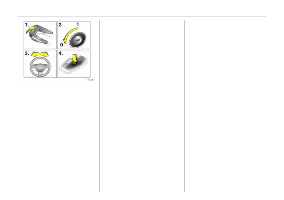
Fault
If automatic opening a nd closing of the
windows is not possible, activate the
window electronics as follows:
1. Close doors.
2. Sw itch on ignition.
3. Open windows comple tely.
4.Close the window and hold the button
depressed at least 5 seconds.
5. Repeat for each window.
Sunblind on panoramic roof 3
To reduce the am ount of glare in the
interior.
To op en
Press button G and sunblind opens as far
as it will go.
To clo s e
Press button H.
For reasons of safety, the blind closes from
its open position to approx. 20 cm. Hold
down button H to close comple tely.
Page 53

49Seats, Interior
Seats, Interior
Fron t sea ts .. ......... ......... ......... ........ ...... 49
He ad re strain ts ........ ......... ......... ......... . 5 1
Armrest 3 .... ............. ..... .... ............. ..... . 5 2
Moving third row sea ts uprigh t .... ..... . 5 3
Luggage compartment extension ..... 54
Luggage compartment cover 3........ . 57
Safe ty ne t 3 .... ..... ............. ..... .... .......... 58
Lashing eyes 3 .... .... ......... ..... .... .......... 60
Rails 3 and hooks 3 in luggage
compartment..... .... ..... ............. .... ..... . 60
FlexO rganizer 3... ............. ..... .... .......... 60
Floor covering 3 in lugga ge
compartment..... .... ..... ............. .... ..... . 62
Notes on loading the ve hic le ........ ...... 62
Three -stage restraint system ........ ...... 63
Three -point se at belts ............... .... ...... 6 3
Be lt tensione rs. ..... ............. ..... .... .......... 64
Using the be lts .................. ..... ........ ...... 6 5
Child restraint systems 3 . ..... ............. . 68
Mounting brackets 3 for ISO-FIX child
restraint s ys tem s ........ ......... ........ ...... 68
Fastening eyes 3 for Top-Tether child
restraint s ys tem s ........ ......... ........ ...... 69
Airbag system ...... ......... ......... ........ ...... 69
Cigarette lighter 3... ..... ......... .... .... ...... 78
Accessory socket 3.. ..... ............. .... ..... . 78
Ashtrays 3............ .... ..... ......... .... .... ..... . 79
Foldaway tables 3 ....... .... ..... ........ ..... . 7 9
Stowage comp artments............ .... ...... 7 9
Drink holders 3 .... .... ......... ..... .... .......... 81
Sun visors.. .... ............. ..... .... ............. ..... . 8 1
Front seats
9 Warning
Important: Do not sit nearer than
10 inches (25 cm) from the steering wheel,
to permit safe airbag deployment.
Never adjust seats whilst driving as they
could move uncontrollably.
Adj ust s ea t lon g it udi na ll y
To adjust, pull handle on front seat, slide
seat and release handle.
Adjust seat backr est
To adjust, turn handwheel at side of seat
while releasing any load on the seat
backrest.
Move seat backrest to suit sea ting position.
Adjust seat h eigh t 3
Page 54

50 Seats, Interior
To adjust, use lever on the outside of the
seat.
Lever pumping m otion
Up: Seat higher
Down: Seat lower
Adjust seat incline 3
To adjust, pull inner lever on front of seat,
adjust incline and release lever.
Allow the seat to engag e audibly
Th e incline is a djus ted by shifting yo ur
body weight.
Adjust lumbar suppo rt 3
To adjust, turn handwheel on side of seat
backrest, releasing the load on the
backrest.
Adjust lumbar support to suit personal
re q u ir em e n t s.
Adjust thigh support 3 of sports
seats 3
To adjust, press button at the front of
the adjustment cushion and slide thigh
support.
Adjust thigh support to suit personal
requirements.
Seat position
Adjust driver’s seat such that with the
driver sitting upright the steering wheel is
held in the area of its upper spokes with the
driver’s arms slightly bent.
Push front passenger’s seat as far bac k as
possible.
Page 55

51Seats, Interior
The seat backrests must not be tilted too
far back (recomm ended max im um tilting
angle approx. 25°).
9 Warning
Failure to observe the instructions could
lead to injuries which could be fatal.
Vehicle passengers must be informed
accordingly before starting-off.
Head restraints
Adjusting the front head restraints
and outboard rear head restraints in
the second seat row
To adjust, press button on side and adjust
height.
If the seats are occupied, a djust height
according to body size.
Adjusting the head restraints of the
centre seat in the second row and the
head r estraints of the seats i n the
th ird ro w
To adjust, pull the head restraint up or
press the catch to r e leas e. Then pu s h the
head restraint down.
To fold the seats or in order to improve
visibility when the seats are unoccupied,
fold headrests all the way down.
If the seats are occupied, adjust height
according to body size.
Head r estraint position
Th e middle of the h ead restraint s hould be
at eye level. If this is not possible for
extremely ta ll persons, set to highest
position, and set to lowest position for
small persons.
9 Wa rn ing
Failure to observe the descriptions could
lead to injuries which could be fatal.
Vehicle pa ssenge rs m ust be inf orm ed
accordingly before starting-off.
Page 56

52 Seats, Interior
Active head restraints 3
In the event of a rear-end impa ct, the
active head restraints tilt forwards.
Th e head is more effectiv ely suppor ted by
the head restraint and the danger of
whiplash in the neck area of the cervical
vertebra is reduced.
Active head restraints are identified by the
lettering ACTIVE on the head restraint
guide sleeves.
Remov i ng the head res trai nts
Press and release the two catches. Pull and
remove the head restraint.
Note
Only attach loose objects or components
to the head restraint on the front
passenger’s seat if it is not in use.
Armrest 3
Arm rest at driver’s s eat
Push raised armrest ba ckwards against
resistance and fold down.
Th e armres t can be move d to d ifferent
positions in stages by lifting it.
Page 57

53Seats, Interior
Armrest in folded-down centre
backrest
Slide centre head rest all the way down b y
pressing the catches – see page 51.
Pu ll handle at bac k of ce ntre backrest, fold
backrest onto se at cushion and e ngage –
see page 56.
The centre seat backrest can be used as an
armrest when folded down, and contains
drin k h olders and stowag e compa rtm ents.
To erect the seat backrest, pull handle on
backrest, straighten backrest and engage.
Moving third row seats upright
9 Warning
Keep hands away from hinge area when
the seats are being moved upright, - risk
of injury.
Remove floor covering 3.
Removing luggage compartment cover 3 –
see page 57.
Before moving the seats upright, slid e seat
bench of second row of seats forwards by
pushing forward the lever at the right or
left-hand side of the seat bench. The tip of
the arrow at the seat bench must be in
front of the square mark. Slide front seats
forwards a little if necessary.
The seat belts must be routed through the
belt holder as shown in the illustration. The
latch plates must be inserted in the holder.
9 Wa rn ing
In the version w ith FlexOrganizer 3 – see
page 60, the belts must be suspended in
the right and left seat belt eyes on the
floor of the vehicle without twisting, see
Fig. 17420 T on page67.
All components must be removed from
the rails in the luggage comp artment.
Page 58

54 Seats, Interior
From luggage c om partment, use one han d
to lift seat by the handle, swivel back and
move upright until it audibly engages. Use
other hand to support top of backrest, see
Fig. 17372 T.
Lift up cover in floor between the seats and
swi v el be lt b u ckle s upwa rd s, see Fig.
17386 T.
Remove latch plate and belt from fixture.
9 Warning
The belt must not be routed through the
belt holder when the seat belt is being
worn.
Move seat bench in second row of seats to
required position and engage by pushing
lever on right or left-hand side of seat
bench forwards – see pag e 20,
Fig. 17367 T.
Fit luggage compartment cover 3 by
fitting behind the third row of seats –
see page 58.
Luggage compartment
extension
The greatest a mount of luggag e
compartment space is obtained by
removing the lugga ge compartment
cover 3 and fo lding the seats o f the second
and third row as well as the front
passenger’s seat 3, see following
description.
9 Wa rn ing
Keep hands away from hinges when
folding seats or rows of seats, risk of
injury.
The backrests of the seats in the second
row may only be moved to the vertical
position or tilted forwards in order to
extend the luggage compartment.
Passengers must not sit in the seats if they
are in this position.
Page 59

Lowering seats in third row into floor
of vehicle
55Seats, Interior
Remo ving luggage com partment c over 3 –
see page 57.
Before folding the seats in, slide seat bench
of second row of seats forwards by pushing
forward the lever at the right-hand or
left-hand side of the seat bench. The tip of
the arrow at the seat bench m ust be in
front of the square ma rk. Slide front seats
forwards a little if ne cessary.
Pu sh down head restraints of seats in third
row – releasing spring catches by pressing.
Guide seat belts through holder as shown
in illustration and insert latch plates into
holde r .
If th e F lex Organize r 3 components are
used – see pag e 60 , the seat be lts of the
third row of seats can be unhooked from
the floor of the vehicle – see page 67,
Fig. 17420 T. Secure detached belt hooks
to holder magnets – see page 60
Fig. 17399 T.
From luggage compartme nt, press button
at top of seat backrest and swivel backrest
forward. Raise seat by handle at rear and
swivel backrest further forwards until seat
is lowered into vehicle floor.
Hold seat b y ha ndl e du ring the ent ire
swivelling procedure.
Lower both seats if required.
Page 60

56 Seats, Interior
Push belt buckles into recess in floor and
close cover.
Move seat bench in second row of seats to
required position and engage by pushing
lever on right or left-hand side of seat
bench forwards – see page 20, Fig.
17367 T.
Fit luggage compartment cover 3 behind
second row of seats – see page 57.
Raising seats in third row – see pag e53.
Luggage compartment cover 3 –
see page 57.
Safe ty ne t 3 – see page 58.
Lashing e yes – see page 60.
FlexO rganizer 3 – se e page 60.
Folding down b ackrests of outboard
seats in second row
Remove luggage compartment cover 3 if
necessary – see page 57.
Press side knob and slide down head
restraints of outboard seats in second row.
Place seat belt buckles in pockets in se at
bench.
Push down release lever at one or both
backrests, then move backrests to a
vertical position or tilt forwards or fold flat
onto seat bench and engage.
To move upright, push release lever down
and latch backrest in required position.
Fo ldin g do wn cen tre ba c kres t in
second sea t row
Push centre head restraint down as far as
possible, pressing catches to release.
Place seat belt buckles in pockets in seat
bench.
Pull upper handle on rear of centre
backrest, move backrest to a v ertical
position or fold flat on to seat cushion and
engage.
To move seat upright, pull front handle of
folded-over backrest, move upright and
engage in required position.
Lower second row and push forwards
Remove luggage compartment cover 3 if
necessary – see page 57.
Slide head restraints down by pushing
knobs at side and releasing catches.
Place seat belt buckles in seat bench
pockets.
Page 61

57Seats, Interior
Raise se at cushion in second row by
pushing handle 1 on right or le ft hand s ide
of seat bench down and p ushing up seat
bench until it locks into position.
Push down release lever 2 at both
outboard backrests, raise backrests and
latch into position.
Pull top handle on back of centre backrest,
move backrest to vertica l position and
latch into position.
Push down lever 3 to right or left of seat
bench, move seat bench as far forwards as
possible and latch into position.
To move upright, press lever 3 and slide
seat bench to req uired position. Adjust
backrest angles and swivel seat cushion
down using lever 1. All positions must
audibly latch.
Folding down the front passe nger ’s
seat 3
Press knob at side and slide front
passenger’s seat head restraint
downwards.
Push front p ass enge r’s seat ba ck wards .
Fold front passenger’s seat forwards by
ra ising re lease lev er and latch into p osition.
Straighten front passe nger’s seat
ba ck re st 3
Raise release lever and allow front
passenger’s seat backrest to e ngage
audibly.
Not es on load ing –
see page 62.
Luggage compartment cover 3
Do not place any heavy or sharp-edged
objects on the cover.
Before operating the luggage
compa rtment cover, the rear seat belts
must be fed through the side belt holders,
see Fig. 17390 T.
Secure unhooked hooks 3 of se at b e lts of
third row of seats to side holder magnets –
see page 67, F ig. 17399 T.
To close:
Pull the cover towards the rear using the
handle and engage it in the retainers at the
sides.
To open:
Remove luggage compartment cover from
side brackets. It rolls up automa tically.
Page 62

58 Seats, Interior
Removing
Open the luggage compartment cover.
Move release lever on right side of luggage
compartment cover upward. Lift right
cover and remove from brackets.
Fitting
Insert luggage compartment cover in
aperture, pull release lever at right side
upwards, insert right luggage
compartment cover and engage.
Stow age in front of tailga te
With the third row of seats up right, stow
luggage compartment cover in rear
position: insert left luggage compartment
cover into aperture, fold re lease lever at
right-hand side upwards, insert and
engage righ t luggage comp artment co ver.
Safety n et 3
The safety net can be fitted behind the
se cond row of s eats or, if the se ats in the
second row are folded, behind the front
se ats.
Passengers must not be transported
behind the safety net.
Fitting
Th ere are two in stallatio n open ings in the
roof frame: suspend and engage rod of net
at one side, compress rod and suspend
and engage at other side.
Suspend hooks of net tensioning belts in
lash ing eye s in flo or b ehind th e s econd row
of seats and tension,
– or –
Page 63

59Seats, Interior
Suspend hooks of net tensioning belts in
slots behind front seats and tension.
Removing
Raise length adjuster of the net tensioning
belt and move belt to one side. Comp ress
the upper net rod and rem ove from the
fitting openings.
Stowage of safety net
Remove safety net. Place tensioning straps
as shown in illustration and align to net.
Roll the upper net rod down to
approximately over the middle.
Place the upper net rod over the tensioning
straps next to the lower net rod. The hooks
on the upper net rod must point away from
the lower net rod.
Fasten Velcro tape tightly about the net
next to the length adjusters. The length
adjusters and net rods must lie flat next to
each other, see illustration.
Push down lower lever to right or left of
seat bench to raise seat bench of second
row of seats – see page 56. Slide safety net
into receptacle beneath seat bench, fold
seat bench downwards and engage .
Page 64

60 Seats, Interior
Lashing eyes 3
Lashing e yes in the luggage compartment
serve to secure items being transported
against slippage, e.g. using lashing
straps 3, a luggage net 3 or safe ty net 3.
In v ersion with FlexOrgan izer 3 the eyes for
securing the removable seat belts must not
be used as lashing eyes.
The seat belts in the third row of seats must
never be used for securing loads.
Rails 3 and hooks 3 in luggage
compartmen t
The side walls o f the luggage compartm ent
house two ra ils. Insert the hooks in the
desired position in the rails: insert the hook
in the upper groove on the rail and press in
the lower groove.
Pull off the hook to remove.
When the FlexOrganizer rails and
components 3 are being used (with the
exception of the partitioning net in front of
the tailgate) – see page 61, the seats in the
third row must be folded in – see page 55,
and the seat belts must be unhook ed from
the floor – see page 67, Fig. 17420 T.
Secure released seat belt hooks to belt
holder magnets – see page 67,
Fig. 17399 T.
FlexOrganizer 3
Flex ib le system for dividing the lu gga ge
compa rtm ent or securing the load .
When the FlexOrganizer components are
being used (with the exception of the
partitioning net in front of the tailgate),
the seats in the third row must be folded
in – see page 55, and the seat belts must
be unhooked from the floor – see page 67,
Fig. 17420 T. Secure released seat belt
hooks to belt holder magnets, see
Fig. 17399 T.
Page 65

61Seats, Interior
The system consists of
z adapters
z variable partition net
z mes h pocke ts for t h e side wal ls
z hooks in the lugga ge compartment
The components are fitted in two guide
rails in the side panels of the luggage
compartment using adapters and hooks.
The partitioning net can also be fitted in
the frame in front of the tailgate.
Vari able p artitio n net
Insert an adapter into each rail: fold open
the handle plate, insert adapter into upper
and lower groove of rail and move to
required position. Swivel handle plate
upwards to lock the adapter. The rods of
the net must be extended before inserting
into the adapters: pull out each of the four
end pieces and lock by rotating clock wise.
To install, push rods together a little and
insert into the relevant openings in the
adapters. The longer rod must be inserted
into the upper adapter.
Luggage hooks and net pocket
Insert luggage hooks into required position
in rails: to do this, insert hooks in upper
groove of rail and push into lower groove.
Net pocket can be suspended from the
luggage hooks.
P ar titi on in g ne t in fr on t of ta ilg a te
Page 66

62 Seats, Interior
The partitioning net can be fitted in the
recesses in the panel in front of the tailgate
with the third row of seats upright. This
prevents the load from falling out when the
tailgate is opened.
Th e fou r rod end pieces of the net m ust be
pushed in before installation by rotating
each end piece anticlockwise and pushing
in.
To install, push rods of partitioning net
together a little and insert into the relevant
openings in the panel. The longer rod must
be inserted at the top.
For easier lo ading with the third row of
seats upright, first insert the rod, load the
luggage compartme nt and then insert the
upper rod.
Removing
Push rod of partitioning net together and
remove from the adapters and the recesses
in the panel.
Adapter: fold open the retainer, release the
adap ter f rom the lowe r groo ve and remov e
from the upper groove.
Disengage luggage hook from the rails.
Floor covering 3 in luggage
compartment
When the third row of seats is not in use
and are –folded away– a cover can be
placed over the luggage compartment
floor.
Notes on loading the vehicle
z Heavy objects in the luggag e
compa rtment should be placed against
the engaged rear seat backrests or, if the
rear seat backrests are folded down,
against the front seat ba ckrests. If
objects are to be stacked, the heavier
objects should be placed at the bottom.
Unsecured objects in the luggag e
compartment would be thrown forwards
with great force in the event of heavy
braking, for example.
z Secure heavy objects with lashing
straps 3 attached to lashing eyes –
see page 60. If heavy loads slip when
the vehicle is braked heavily or driven
around a bend, the handling of the
vehicle may change.
z Secure loose articles in luggage
compartment using FlexOrganizer 3 or
luggage net 3 to prevent sliding.
z When transporting objects in the
luggage compartment, fit safety net 3 –
see page 58.
z Close the luggage compartment cover 3
to prevent the objects from being
reflected in the rear window.
z If the b ackrests are n ot folde d down
when transporting objects in the
luggage compartment, they must b e
engaged in their upright position –
see page 56.
z Do not allow the load to protrude above
the upper edge of the backrests of the
se ats in the se cond r o w or, if th e se cond
row seats have been removed, above the
upper edge of the front seat backrests.
z The warning triangle 3 and first-aid kit
(cushion) 3 must always be free ly
accessible.
z Do not place any objects on the luggage
compartment cover 3 and on the
instr umen t pa nel. They are reflected in
the glass, obstruct the driver’s view and
will be thrown through the vehicle in the
event of hard braking, for example.
z Obje cts m ust not be store d in t h e a irb ag
inflation area, because they could cause
injury if the airbag system is triggered.
z The load must not obstruct the operation
of the pedals, handbrake and gear
selector, or hinder the freedom of
move ment of the driver. Do not place
any unsecured objects in the interior.
Page 67

63Seats, Interior
z Do not drive with luggage compartment
open wh en transporting bu lky objects,
for example, since toxic exhaust fumes
could penetrate the interior.
z Weights, payload a nd roof load –
see page 217.
z Driving with a roof load increases the
sensitivity of the vehicle to crosswinds
and has a detrimental effect on vehicle
handling due to the vehicle’s higher
centre of g ravity. For driving with a roof
load – see pages 142, 144, 164.
9 Warning
Disreg ard of th es e instructions may lead
to injuries or e nd anger lif e. Veh icle
pass en ge rs must b e in formed
accordingly.
Three-stage restraint system
Com prising:
z Three-point seat belts,
z Belt tensioners at the front seats,
z Airbag systems for driver ’ s sea t, f ront
passenger’s seat and the outboard seats
of the second row of seats 3.
The three stages are activated in sequence
depending on the seriousness of the
accident:
z The automatic seat belt locking devices
prevent the belt strap from b eing pulled
out and thus ensure that the vehicle
occupants are retained in their seats.
z The front seat belts are pulled down at
the belt buckles. This means the belts fit
snugly, the occupants are decelerated
early with the vehicle and the body
loading is reduced.
z The airbag systems are also triggered in
th e ev en t of s eri ou s ac cid e nt s an d f o rm a
safety cushion for the occupants.
Depending on the severity of the
accident, the front airbags inflate in two
stages.
9 Warning
The airbag systems serve to supplement
the three-point seat belts and belt
tensioners. The seat belts must therefore
alway s be w orn. Disreg ard of these
instructions may lead to injuries or
e nd ang er li fe . V ehi cle p as se n ger s m u st be
informed accordingly .
Read the instructions supplied with the
child restraint system!
Three-point seat belts
The vehicle is equipped with three-point
seat belts with automatic retractors and
locking d evices, allowing freedom of body
movement although the spring tensioned
belts always ensure a snug fit.
For information on correct seating
position – see pages 50, 65, 70.
Th e belts are loc ked during heavy
acceleration or deceleration of the vehicle.
9 Wa rn ing
Alw ays we ar your seat belt, and that
means also in urban traffic and when you
are a rear seat passenger. It can save
your life!
Also, pregnant women must always wear
a seat belt – see page 65.
Page 68

64 Seats, Interior
In the event of an accident, persons not
wearing seat belts endanger their fellow
occupants and themselves.
Control indicator X 3 for the seat belt –
see page 84.
Seat belts are only designed for use by one
person at a time. They are not suitable for
persons younger than 12 years of age or
smaller than 150 cm.
For childre n up to 1 2 yea rs of ag e, w e
recommend the Vauxhall child restraint
system – see page 68.
Belt f orce limiters
Belt force limiters on the front seats reduce
the body load due to damped release of
the belt on a collision. This means that the
occupants move forwards under control.
Inspection of belts
Check all parts of the belt system
occasionally for damage and function.
Replace damaged parts. Following an
accident, have the belts and deployed belt
tensioners replaced by a workshop.
Do not perform a ny alterations on the
be lts, the ir anch orages , the au tom atic
retractors or the belt buckles.
Make sure that belts are not dam aged or
trapped by sharp-edged objects.
Belt tensioners
The front seat belts are fitted with belt
tensioners. The seat belts are pulled down
at the buck les on a front or rear-impac t
above a certain severity. This tightens the
belts.
Actuation o f be lt t ens ion ers
Actuation of belt tensioners is indicated by
illumination of control indica tor v, see
Fig. 17105 T.
If the belt tensioners are deployed, these
must be replaced by a workshop.
Further information – see page 65.
Co ntrol indi cator v fo r be lt
tensioners
The function of the belt tensioners is
monitored electronically together with the
airbag systems and indicated by control
indicator v . When the ignition is switched
on, the control indicator illuminates for
approx. 4 seconds. If it does not illuminate,
does not go out after 4 seconds or
illuminates whilst driving, there is a fault in
the belt tensioner or and airbag systems.
Th e sys tems may f ail to trigge r in the e vent
of an accident.
Deployment of the belt tensioners is
indicated by continuous illumination of v.
9 Wa rn ing
Immediately rectify the cause of the fault.
Self-diagnosis integrated into the system
facilitates rapid rectification of faults.
Page 69

65Seats, Interior
Important
z Accessories and other objects not
specifically approved for y our vehicle
type must not be affixed or placed within
the action zone of the belt tensioners
(near the belt buckles) as this could
result in injury if the belt tensioners are
tr ig g e r ed .
z Do not m ake any modifications to the
components of the belt tensioners, as
this will render the vehicle unroadworthy.
9 Warning
Incorrect handling (e.g. removal or fitting
of b elts or belt buckles) can trigge r the
belt tensioners with risk of injury.
z The belt tensioner and airbag system
control electronics can be found in the
centre console area. In order to avoid
malfunctions, do not store magnetic
ob jects in t hi s ar e a.
z When using the rear seats, ensure that
the front belt components are not
damaged by shoes or other objects.
Avoid dirt getting into the retractors.
z We recom men d th at y ou ha ve th e fr o nt
se ats remo ved by a works hop in the
event of actuation of the belt tensioners.
z The belt tensioners are deployed once
only, indicated by illumination of v.
Deployed belt tensioners must be
replaced by a workshop.
z When disposing of the vehicle, the safety
regulations applicable to this must be
observed. Have the vehicle disposed of
by a company which reuses vehicle
parts.
Using the belts
Fitting the belt
Pull the belt out of the retractor and guide
it across the body, making certain that it is
not twisted.
Insert the latch plate into the buckle.
The f ront se at back rest must n ot be tilted
back too far or the seat be lt will not
operate properly. The re comme nd ed
maximum angle of inclination is 25°. Make
sure that the lap belt is not twisted and
that it fits snugly across the body. Tension
the belt frequently whilst driving by
tugging the diagonal part of the belt.
9 Wa rn ing
On pregnant women in particular, the lap
belt must be positioned as low as possible
across th e pelvis s o as not to pu t too m uch
pressure on the abd om en.
Thick lay ers of clothing prevent the belt
from fitting snugly. The belt must not rest
against hard or fragile objects in the
pockets of your clothing (e.g. ballpoint
pe n, ke ys, specta cles ), s ince this co uld
cause injury. No objects such as handbags,
mobile phon es etc. must be present
between the belt and y our body.
Page 70

66 Seats, Interior
Height adjustment
Height adjustment of the upper anchorage
point of th e front belt and outboard belts in
the second seat row:
1. Pull belt out slightly.
2.Press down button on adjuster slide.
3. Move a djuster slide up or down.
4. Allow sliding adjuster to audibly latch.
Do not adjust height whilst driving.
Adjust height such that the belt passes
over the wearer’s shoulder and rests
against the shoulder. It must not pass over
the neck or upper arm.
Re movi ng the belt
To re move the belt, depress the red push
button on the buckle; the belt will retract
automatically.
Seat belts in th e s ec on d row
When adjusting second seat row to enlarge
luggage compa rtm ent, place seat belt
buckles in pockets in seat bench as shown
in illustration.
The seat belt for the centre seat can only
be pulled out of the inertia reel if the
backrest is latched in the rearmost
position.
Page 71

67Seats, Interior
Seat belts in the third row
Open the cover in the floor between
the seats and pull up the belt buckles.
Remove latch plate and seat belt from belt
holder.
9 Warning
The belt must not be routed through the
belt h older when the se at belt is being
worn.
Unhookable seat belts 3 in the th ir d
row
To make better use of the rails and
Flex Organ ize r components 3 in the
luggage compartment, the seat belts in the
third row of seats ma y be removed from
th e s eat belt eyes on th e floor of the ve hicle
when the seats are folded down.
Wh e n not in us e, route th e s eat belt
through the belt holder as shown in the
illustration, and insert the latch p la te into
the holder.
To do this, press spring-load ed tab and
unhook hooks from the seat belt eyes on
th e flo or o f the veh icle. Re el up th e seat belt
and a tta ch hooks to magnet of seat belt
holder, see Fig. 17399 T.
To reinstall the seat belt, remove hook from
magnetic holder, push spring-loaded tab
at hook and fit seat belt eye in floor of
vehicle. The seat belt must not be twisted
and the hook must be properly engaged in
th e seat be lt ey e with th e sp ring-lo ade d
tab closed again.
Page 72

68 Seats, Interior
To move the seat belts for the third row of
seats as shown in Fig. 17370 T on page 67,
feed through a belt holder and insert latch
plate in bracket.
9 Warning
Before moving the third row of seats
upright, all components must be removed
from the rails in the luggage
compartment a nd the seat belts
suspended in the sea t belt eyes in the
floor of the vehicle without twisting.
The belt must not be routed through the
belt h older when the se at belt is being
worn.
Important
z Unhookable seat belts in the third row of
seats are identified by a marker label on
th e be lt.
z When the seat belt is being worn, the
seat belt hook must be installed in the
eye in the floor o f th e v ehicle an d th e
seat belt must not be led through the
se at be lt holde r.
z The unhooked seat belts in the third row
of seats may only be attached to the
provided e yes in the floor of the ve hicle –
see page67, Fig. 17420 T.
z The eyes and the seat belts of the third
row of seats m ay not be used for lashing
lo a d s .
z There must be no objects in the seat belt
hooks.
Child restraint systems 3
When using a child restraint system, note
the instructions for installation and use.
The country in which you are travelling
may not permit the use of child restraint
sy st e ms on certa in seats. A lway s c om ply
with the local or national regulations.
Selec ting th e right s yste m
Your child should travel facing backwards
in the vehicle for as long as possible. A child
has a v ery weak cervical spinal column and
in the event of an ac cident is less likely to
suffer injury in a rearward-facing, semilying position than if seated upright.
Permitted options for child restraint
mounting – see page 228.
9 Warning
Never carry child restraint systems on
your lap, risk of fatal injury.
Note
z C hil dre n un der 1 2 ye ars or un de r 1 50 c m
tall should only travel in an appropriate
child safety seat.
z When transporting children, use the child
restraint systems suitable for the child’s
weight.
z Ensure corre ct installation of child
restra int syste m, se e th e instruct ions
enclosed with the system.
z The covers of the Vauxhall child restraint
system can be wiped clean.
z Do not stick anything on the child
restraint systems and do not cover them
with any other materials.
z Only allow the child to enter and exit on
the side of the vehicle facing away from
the road.
z A child restraint system which has been
subjected to stress in an accident must
be re placed.
z Secure or remove child restraint systems
carried in the vehicle when not in use.
Mo un ti ng b ra cke ts 3 for ISO-FIX
child restraint systems
The brackets located between the backrest
and seat cushion are used for mounting
ISO-FIX child restraint systems.
The instructions ac com panying th e ISO-FIX
child restraint system are to be expressly
followed.
O n ly ISO -F IX ch ild res trai nt sy ste ms
permitted for the vehicle may be used.
Page 73

69Seats, Interior
Fastening eyes 3 for Top-Tether
child restraint systems
Th ere are tw o eye s for cen tral attachme nt
of Top-Tether child restra int systems in the
crossmember behind the outboard
backrests of the second row of seats.
Th e strap of the Top -Tether child re straint
system must run below the head restraint
between the two guide rods.
Please be sure to follow the instructions
provided with the Top-Tether child
restraint system.
When using ISO-FIX and Top-Tether for
seat m ounting, universally permitted child
restra int sy ste ms for IS O-F IX may be used.
Airbag system
Front airbag
The front airbag system is identified by the
word AIRBAG on the steering wheel and
above the glove compartment.
The front airbag system comprises:
z an airbag with inflator in the steering
wheel and a second one behind the trim
panel above the glove compartment,
z control electronics with impact sensors,
z control indicator for airb ag systems v in
instrument cluster,
z seat occupancy recognition 3,
z the control indicator for Vauxhall child
restraint systems y with transponders 3
in the instrum ent cluster.
The front airbag system is triggered:
z depending on the severity of the
accident,
z depending on the type of impact,
z within the range shown in the illustration,
z independent of side airbag 3 and
curtain airbag system 3.
Exception:
Front passenger’s seat with seat
occupancy recognition system 3. The seat
occupancy recognition system deactivates
the front and side airbags 3 on th e
passenger’s side if the front passenger’s
seat is unoccupied or a Vauxhall child
restraint system w ith transponders 3 has
been fitted to the front passenger’s seat.
For seat occupancy recognition – see
page 74. For Vauxhall child restraint
system with transponders 3 – see p age 77.
Page 74

70 Seats, Interior
Examples of events triggering the front
airbag system:
z Impact a gainst a non-yielding obstacle:
the front airbags are triggered at low
vehicle speed.
z Impact against a yielding obstacle (such
as another vehicle): the front airbags are
only triggered at a higher vehicle speed.
When triggered, the front airbags inflate in
milliseconds to form a safety cushion for
th e d riv er an d fron t passenger. Th e
forward movement of the front seat
occupants is checked, thereby
substantially reducing the risk of injury to
the upp er body and hea d. No impairme nt
of view will occur, because the airbags
inflate and deflate so quickly.
9 Warning
The front airbag system provides
optimum protection when the seat,
backrest and head restraint are correctly
adju s ted: A djust the driver’s seat
according to the occupant’s height such
that with the driver sitting upright the
steering wheel is held in the area of its
upper sp okes with the d riv er’s ar ms
slight ly be nt. The fro nt p as se ng er’s s eat
should be as far back as possible, with the
backrest upright – see pages 3, 49, 50.
Do not place the head, body, hands or
fee t on th e c overs of the airbag systems.
Do not place any objects in the area in
which the airb ags inflate. Important
information – see page 75.
9 Wa rn ing
The three-point seat belt must be
correctly fitted – see page 65.
The front airbag system will not be
triggered in the event of
z the ignition being switched off,
z minor frontal collisions,
z accidents in which the vehicle overturns,
z collisions involving a side or rear-impact,
Page 75

71Seats, Interior
that is to say, if it would not be of benefit to
the occupants.
9 Warning
Seat belts must a lw ays be worn. The front
airbag system serves to supplement the
three-point seat belts. If you do not wear
yo ur se at be lt you risk bein g se riou sly
inju red, or ev en thro wn from th e v ehicle,
in th e ev ent of an acc ident.
If an accident occurs the belt he lps to
maintain the correct seat position that is
required for the front airbag system to
provide y ou with effective protection.
In addition, the front airbag system will
not be triggered for the front passenger’s
seat in v ersions with seat occupancy
recognition 3 if
z the front passenger’s seat is unoccupied,
z there is a prop erly fitted Vauxhall child
restraint system with transponders. For
seat occupancy recognition – see
page 74. For Vauxhall child restraint
system with transponders – see page 77.
Side airbags 3
The side airbag system is identified by the
word AIRBAG on the outboard sides of the
front seat backrests.
The side airbag system comprises:
z an airbag with inflator in the back of the
driver’s and front passenger’s seat
respectively,
z the control electro nics,
z the side-impact sensors,
z control indicator for airb ag systems v in
instrument cluster,
z seat occupancy recognition 3,
z the control indicator for Vauxhall child
restraint systems y with transponders 3
in the instrum ent cluster.
The side airbag system is triggered:
z depending on the severity of the
accident,
z depending on the type of impact,
z within the range shown in the illustration
on the centre door pillar of the driver’s or
front passenger’s side,
z independently of the front airbag
sy ste m.
Page 76

72 Seats, Interior
Ex cep tion :
Front pa ssenger’s seat with seat
occupancy recognition system 3. The seat
occupancy recognition system deactivates
the front and side airbags 3 on the front
passenger’s side if the front passenger’s
seat is unoccupied or a Vauxhall child
restraint system with transponders has
been fitted to the front passenger’s seat.
For seat occupancy recognition – see
page 74. For Vauxhall child restraint
system with transponders – see page77.
When triggered, the side airbag inflates
within milliseconds to form a safety cushion
for the driver or front passenger in the
respective door area. This substantially
reduces the risk of injury to the upper body
and pelvis in the event of a side-on
collision.
9 Warning
There must be no objects in the area in
which the airbag inflates or in the area
between the seat backs and the vehicle
body. Do not place the hands or arms on
the covers of the airbag systems.
Important information – see page 75.
The three-point seat belt must always be
correctly fitted – see page 65.
The side airbags will not be triggered in the
eve nt of
z the ignition being switched off,
z frontal collisions,
z accidents in which the vehicle overturns,
z collisions involving a rear-impact,
z Sid e-on collisions outside the passenger
cell.
In addition, the side airbag system3 will
not be triggered for the front passenger’s
seat in versions with seat occupancy
recognition 3 if
z th e f ront pas seng er’s s eat is un occupied,
z there is a properly fitted Vauxhall child
restraint system with transponders.
For seat occupancy recognition – see
page 74. For Vauxhall c hild restraint
system with transponders – see page 77.
Curtain airbag 3
The curtain airbag system is identified by
the word AIRBAG on the roof pillar trim.
The curtain airbag system comprises:
z an airbag with inflator in the roof frame
on the driver’s and front passenger’s side
respectively,
z the control electronics,
z the side-impact sensors,
z control indicator for airbag systems v in
instrument cluster.
Page 77

73Seats, Interior
The curtain airbags will not be triggered in
th e eve nt of
z the ignition being switched off,
z frontal collisions,
z accidents in which the vehicle overturns,
z collisions involving a rear-impact,
z Side-on c ollisions outside the passenger
cell.
Co ntrol indi cator v fo r airbag
sys tem s
The curtain airbag system is triggered:
z depending on the severity of the
accident,
z depending on the type of impact,
z within the range shown in the illustration
on the centre door pillar of the driver’s or
front passenger’s side,
z together with the side airbag system 3,
z irrespective of seat occupancy
re c og ni t ion 3,
z independently of the front airbag
sys tem .
When the curtain airbag is triggered it
inflates within milliseconds and provides a
safety barrier in the head area on the
respective side of the vehicle. This reduces
the risk of injury to the head considerably in
case of a side-impact.
The curtain airbag system does not protect
persons in the seats in the third row of
se ats.
9 Warning
There must be no objects in the area in
which the airbag inflates or in the area
between the seat backs and the vehicle
body. Do not place the hands or arms
on the covers of the airbag systems.
Important information – see page 75.
The three-point seat belt must always
be correctly fitted – see page 65.
The function of the airbag systems is
monitored electronically together with seat
occupancy recognition 3 and the belt
tensioners and shown by control
indicator v . When the ignition is switched
on, the control indicator illuminates for
approx. 4 seconds. If it does not illuminate ,
does not go out after 4 seconds or
illuminates whilst driving, there is a fault in
the airbag systems, seat occupancy
Page 78

74 Seats, Interior
recognition 3 or the belt tensioners – see
also page 64. The systems may fail to
trigger in the event of an accident.
Deployment of the airbags is indicated by
continuous illumination of v.
9 Warning
Have the cause of the fault rectified
im m e d ia tel y b y a w o rk sh o p.
Self-diagnosis integrated into the system
permits rapid rectification of faults.
Seat occupancy recognition 3
The se at occupancy recognition system
deactivates the front and side
airbags 3 for t h e front p a ssen ge r’s seat if
the front passenger seat is not occupied or
a Vauxhall child re straint system with
transponders 3 is fitted on the front
passenger’s seat. The curtain airbag
system 3 remains activated.
The c ontrol indicator for seat occupancy
recognition y app ears in th e ins trume nt
cluster. If the control indicator y
illuminates for approx. 4 seconds once the
ignition is switched on, the vehicle is fitted
with seat occupa ncy recognition, see Fig.
17117 T on the next page.
If a Vauxhall child restraint system with
transponders 3 is fitted, the control
indicator y illuminates permanently afte r
switching on the ignition as soon as the
system has detected the child restraint
sy st e m. O nly t h en may a ch ild restraint
sy st e m with tran sponde rs 3 be fitted on
the front passenger’s seat.
Vehicles with seat occupancy recognition
are also identified by a sticker on the lower
panel of the front passenger’s seat –
see illustration ab ove.
Vauxhall child restraint systems with
transponders 3 are automatically
detected if correctly fitted to the front
passenger’s seat. When these child
restraint systems are being used on the
front passenger’s seat, the front and side
airbag systems for the front passenger’s
seat are deactivated. The curtain airbag
system remains activated. Pay attention to
the control indicator y for seat occupancy
recognition 3.
9 Wa rn ing
Only Vauxhall child restraint systems with
transponders 3 can be fitted on the front
passeng er’s seat. Use of systems without
transponders poses a risk of fatal injury.
Vauxhall child re straint systems with
transponders 3 are identified by a stick er
or label.
Co ntrol indi cator y for Vauxhall
child restraint syst ems with
transponders 3
The presence of a V auxhall child restraint
system with transponders 3 is indicated by
the continu o us illuminatio n of co nt r o l
indicator y in the instrument cluster once
th e ignition has been switched on an d the
seat occupancy recognition system has
detected the child restraint system.
Page 79

75Seats, Interior
If the control indicator does not come
on whilst driving, the front and side
airbags 3 for the front passenger’s seat
are not deactivated, and the life of the
child ma y be enda nge red. Fit child
restraint system on the rear seat. Have the
cause of the fault rectified by a workshop.
If the child restraint system is not correctly
installed or the transponder is faulty, the
control indicator flashes. Check for correct
in stallation of child re strain t syst e m.
To install the child restraint system with
transponders 3 – see the instructions
enclosed with the system.
If the control indicator for Vauxhall child
restraint systems with transponders 3
flashes when the child restraint system is
fitted correctly, there is a risk to the child.
Fit child restraint system on the rear seat.
Have the cause of the fault rectified by a
workshop.
If no Vauxhall child restraint systems with
transponders 3 are fitted, the control
indicator must not come on or flash as the
airbag systems for the front passenger’s
seat would not be triggered. Have the
cause of the fault rectified by a workshop.
9 Warning
If the Vauxhall child re straint system with
transponders 3 has been fitted according
to the instructions, the control indicator
for Vauxhall child restraint systems with
transponders must illuminate in the
instrument cluster when the ig nition is
switched on.
If the control indicator does not come on
whilst driving, the airbag systems for the
front passenger’s seat are not
deactivated, risk of fatal injury. Fit child
restraint system on the rear seat. Have
the cause of the fault rectified by a
workshop.
Important
z Accessories and other objects must not
be affixed or placed in the area in which
the airbags inflate as they could cause
injury if the airbags are triggered.
z Do not place any objects between the
airbag systems and the vehicle
occupants; risk of inju ry.
9 Wa rn ing
Never carry child restraint systems or
other objects on your lap, risk of fatal
injury.
z Only use the hooks 3 on the handles in
the roof frame to hang up light articles of
clothing or coat hangers. Do not place
any objects in the pockets of the hanging
items, risk of injury.
z The airbag systems and belt tensioner
control electronics can be found in the
centre console area. In order to avoid
malfunctions, do not store magnetic
objects in this area.
z Do not stick anything on the steering
wheel, instrument panel, front seat
backrests or roof frame, in the vicinity of
the airbags, or on the front p assenger’s
seat cushion, or cover any of those areas
with other materials.
Page 80

76 Seats, Interior
z U se only a d r y cl oth o r inte ri or c le an er t o
clean the steering wheel, instrument
panel, front seat backrests, roof frame
and seat cushion of the front
passenger’s seat. Do not use any
aggressive cleaning agents.
z Only protective covers which are
approved for your vehicle with side
airbag system may be fitted on the front
seats. When fitting the protective covers,
make sure that the airbag units on the
outboard s i d e s of th e fr ont se at
backrests are not covered.
z The airbag systems are triggered
independently of each other depending
on the severity of the accident and the
type of impact. The side airba g system
and the curtain airbag sy stem 3 are
triggered together. See pa ge 74 for
exce ptions.
z Each airbag is triggered once only. Have
deployed airbag s replaced immediately
by a workshop.
z The speeds, directions of movement and
deformation properties of the vehicles,
and the properties of the obstacle
concerned, determine the severity of the
accident and trig gering of the airbags.
The de gree of damag e to y our v ehicle
and the resulting repair costs alone are
not indicative that the criteria for
triggering of the airbags were met.
z Do not m odify airbag system
components, since this would render the
vehicle unroadworthy.
9 Warning
If handled improperly the airbag systems
can be triggered in an explosive manner –
risk of injury!
z We recommend having the steering
whe el, the ins trumen t pane l, all pan elling
parts, the door seals, the handles and
th e seats re move d by a works h o p.
z When disposing of the vehicle, the safety
regulations applicable to this must be
observed. Have the vehicle disposed of
by a company which reuses vehicle
parts.
z Persons weighing less than 35 kg should
only travel on the rear seats. This does
not apply to children who are travelling
in child restraint systems with
transponders 3.
z In v ehicles with seat occupancy
recognition 3, do not place any heavy
objects on the front passenger’s seat
otherwise the airbag systems for the
front passenger’s seat may be triggered
in th e event of an accident.
z In v ehicles with seat occupancy
recognition 3, to prevent malfunctions
do not use protective c overs or e xtra seat
cushions on the front passenger’s seat.
z In order to prevent malfunctions when
using a Vauxhall child restraint system
with transponders 3 on the front
passenger’s seat, no objects (e.g. plastic
sheet, stickers or heated mats) may be
placed under the child restraint system.
9 Wa rn ing
Child restraint systems as well as other
objects must never be carried on the lap
of pass e ngers; risk of fatal in jury . If
carried in this way, child restraint systems
with transponders 3 in vehicles w ith seat
occupancy recognition 3 could lead to
front passenger’s airbag systems not
being triggered in the event of an
accident.
Page 81

77Seats, Interior
Use of child restraint systems 3 on
the f ront passenger’s seat in veh icles
with airbag systems, but without se at
occupancy recognition 3
9 Warning
No child restraint system 3 may be
installed on front passenger’s seat.
Dang er to life.
Versions with front passenger’s seat airbag
can be identified by the word AIRBAG over
the glove compartment and the warning
sticker on the side of the instrument panel,
vis ible whe n th e passenge r’s d oor is open see Fig. 17118A.
The side airbag system 3 is identified by
the word AIRBAG on the outboard sides of
the front seat backrests.
Seat occupancy recognition 3 –
see page 74.
Use of child r estraint syst ems 3 on
front passenger’s seat in vehicles
with airbag systems and seat
occupancy recognition 3
9 Wa rn ing
Only Vauxhall child restraint systems with
transponders 3 can be fitted on the front
passeng er’s seat. Use of systems without
transponders poses a risk of fatal injury.
Vehicles with seat occupancy recognition
are identified by a sticker on the lower
panel of the front passenger’s seat –
see Fig. 17116 T.
Vehicles with seat occupancy recognition
can also be identified by control
indicator y in the instrument cluster.
If control indicator y illuminates for
approx. 4 seconds after the ignition is
Page 82

78 Seats, Interior
switched on, the vehicle is equipped with
seat occupancy recognition – see page 74.
The se at occupancy recognition system
detects Vauxhall child restraint systems
with transponders 3 and deactivates the
front and side airbag systems 3 for the
front passenger’s seat. The curtain airbag
system 3 remains activated. For seat
occupancy recognition – see page 74.
Vauxhall child restraint systems with
transponders 3 can be identified by
a sticker on the child restraint system,
see Fig. 17424T.
Cigarette lighter 3
There is a cigarette lighter in the console
between the front seats.
Press in cigarette lighter. Switches off
automatically once the element is glowing.
Pull out lighter.
Accessory socket 3
Accessory sockets ca n be found in the
console between the front seats, the
console in front of the second row of seats
and on the right in the luggage
compa rtment.
Accessory sockets ca n be used to connect
electrical ac cessories. The battery is
discharged if the engine is stationary.
Do not dam age the sockets by using
unsuitable plugs.
The maximum power consumption of
electrical ac cessories must not exceed
120 watts.
Do not connect any current-delivering
accessories, e.g. electrical charging
devices or batteries.
Electrical ac cessories connected to the
socket must comply with the
electromagnetic compatibility
requirements laid down in DIN VDE 40 839,
otherwise vehicle malfunctions may occur.
Page 83

79Seats, Interior
If the tyre repair kit is 3 is in op eration, no
consumers may be connec ted to the
auxiliary socket.
Ashtrays 3
To be used only for ash and not for
combustible rubbish.
9 Warning
Failure to observe these descriptions can
lead to injuries which may be fatal.
Vehicle passengers must be informed
accordingly.
Ashtray, front
Open ashtray at recess.
Foldaway tables 3
Located on the front seat backrests.
Open b y pulling upward until it engages.
Fold away by pressing down past
the resistance point.
Do not place any heavy objects on
the table.
Stowage compartments
Stowage compartment 3 beneath
front passenger’s seat
To empty th e ashtray, press the spring ,
open ashtray all the way and remove.
As htray so ck et
Lift stowage comp artm ent by grasping
recessed edge and pull out from the front.
Maximum load: 1.5 kg. To close the
stowage compartment, push it in a nd
engage.
For universal use in the centre console, the
door pockets in the inner panelling of all
the doors and in the rear side panelling.
Open cover to use.
Page 84

80 Seats, Interior
Glove c om partment
To open, pull handle.
There is a pen holder on the front of the
open cover.
Th e glov e com partmen t should be close d
while the vehicle is in motion.
Cooled glove compartment 3 –
see page 117.
Stowage compartment for glasses 3
On drive r’s side: fold down to open.
Do not store heavy objects in the stowage
compartment.
Stowage compartments in the roof
pa nelli ng 3
Press marked locations to open.
The maximum permitted load of the two
front stowage comp artments is 1kg, and
the maximum permitted load of the three
stowage compartments in the rear is 2 kg.
Th e stowage compa rtm ents must b e
closed whilst driving.
Page 85

81Seats, Interior
Stowage compartments in the
luggage compartment
Th e veh icle tools with jack 3 and towing
eye and the trailer coupling ball bar 3 are
stow ed beneath a hatch in the vehicle floor
at the rear. To open the hatch, lift the
carpeting then raise, rotate and lift the
ring.
The fusebox is behind the left hatch in the
luggage compartment side panelling –
see page 184.
The tyre repair kit is on the right-hand side
behind the flap 3 – see page 179.
For first-aid kit (cushion), warning triangle
in the luggage compartment –
see page 174.
Dri nk ho lders 3
Drink holders can be found at the front in
the centre console between the front seats,
the door pockets in the inner panelling of
all the doors and in the rear side panelling.
More drink holders can be found in the
centre backrest in the second seat row in
the folded-down position.
Fold centre backrest forwards by pulling
handle on rear of centre backrest.
Sunvisors
The sunvisors can be folded down or
swivelled to the side to prevent dazzling.
While travelling, the covers for the mirrors
in the sunvisors should be closed.
Page 86

82 Instruments, Controls
Instruments,
Controls
Control indicators .................. .... ......... . 82
Instrume nt display... ..... ......... ........ ...... 8 7
Information display . ......... ..... .... .... ...... 89
Warn ing buzzers.. .... ..... ............. .... ..... . 10 2
Windscre en wiper .... ......... ......... ......... . 102
Control indicators
The control indicators described here are not present in all vehicles. The descriptions
however, apply to all instrument versions.
Page 87

83Instruments, Controls
The control indicator colours mean:
z Red
z Yellow
z Green
z Blue
Dang er, im porta nt r e min der,
Warning, information, fault,
Confirmation of activation,
Confirmation of activation.
0
Open & Start system 3, fault
Control indicator illuminates or flashes
yellow.
If i t flas hes
System has not detected electronic key in
vehicle interior. The reasons for this may
be:
– The electronic key is in the wrong
location in the vehicle interior (do
not put key in lugga ge
compartment or in front of
information display), or the
electronic key is not in the vehicle
interior, or influence from an
external interference source (radio
masts, interfering transmitters in the
vicinity).
or
– E lectronic key failure, for emergency
operation – see page 35.
If the battery in the electronic key needs
changing, InSP3 a ppears in the service
display or in vehicles with check control 3
by an appropriate message in the
information d isplay – see pag e 36.
Illumi nated
Fault in O pen&Start sys tem . Wh ere
necessary, lock or unlock the vehicle with
the remote control or emergency key – see
page 37, or attempt to activate using the
spare key.
Emergency operation – see page 35.
If 0 illuminates, this can also mean that
the steering column lock is still locked:
move steering wheel to and fro a little and
press Start/Stop button again.
If 0 illuminates whilst driving a system
error has occurred that ma y eventually
lead to a complete failure.
If 0 illuminates or fla shes: The Start/Stop
button must be held depressed slightly
longer to switch off the ignition. It is
possible that the vehicle will not start
during the next start a ttempt.
If 0 stay s on p erman ent ly or co ntin ues to
flash, seek the assistance of a workshop
immediately.
I
En gine oil press ure
Control indicator illuminates red.
It illuminates when the ignition is switched
on and g oes out shortly after the engine
starts.
Illuminates when the engine is running
Engine lubrication may be interrupted. This
may result in damage to the engine and/or
locking of the drive wheels:
1. Move out of the flow of traffic as quickly
as possible without impeding other
vehicles.
2. Depress clutch.
3. Shift manual transmission or
Eas ytro nic 3 into neutral; for a utomatic
transmission 3, set selector lever to N.
4. Switch off ignition.
9 Wa rn ing
When the engine is off, considerably more
force is needed to brake and steer.
Do not remove key until vehicle has come
to a standstill, otherwise the steering
column lock could engage unexpectedly.
C heck oil leve l bef o r e consu lting a
workshop.
Page 88

84 Instruments, Controls
R
B ra ke s ys te m, clutch sys tem 3
Control indicator illuminates or flashes red.
It illuminates when the ignition is switched
on if the handbrak e is applied or if the
brake or clutch fluid level is too low. Further
information – see pages 158, 205.
For vehicles with Easytronic 3, the control
indicator flashes for a few seconds when
the ignition is turned off if the handbrake is
not applie d.
9 Warning
Illuminated when the handbrake is off:
stop, im mediately stop journey. Seek the
assistance of a workshop.
v
Airbag systems 3, belt tensioners 3
Control indicator illuminates red.
Illuminates when the engine is running
Fault in airbag system or belt tensioners –
see page s 64, 73.
v
Electronic Stability Programme
®
(ESP
Plus)3
Control indicator flashes or illuminates
yellow.
Flashing during driving:
System actively engaged – see page 148.
Illumi nates whilst driving
The sy ste m is off 3 or there is a fault in the
Electronic S tability Programme system –
see page 148.
X
Se at b el t 3
Control indicator illuminates or flashes red.
Once the ignition is switched on, this stays
on until the seat belt is fastened. The
co ntro l indica t o r f las he s when s tarting to
drive.
Fasten seat belt – see page 63.
Q
Door o pe n
Control indicator illuminates red.
It illuminates when a door or the luggage
compartment is open.
p
Alternator
Control indicator illuminates red.
It illuminates when the ignition is switched
on and g oes out shortly after the engine
starts.
Illuminates when the engine is running
Stop and switch off engine. Battery is not
charging. Engine cooling ma y be
in terrupted . In dies el engine s, p ow er to the
brake servo unit may be cut. Check drive
belt condition and tensioning before
contacting a workshop.
W
Coolant temperature
Control indicator illuminates red.
Illuminates when the engine is running
Stop and switch off engine. Coolant
temperature too high: Danger of engine
damage. Che ck coolant level – see
page 204.
Page 89

85Instruments, Controls
A
Engine electronics, tr ansmission
electronics 3, im mobilis er,
die sel fuel filter 3, fault
Control indicator illuminates or flashes
yellow.
It illuminates for a few seconds when the
ignition is switched on.
Illuminates when the engine is running
Fault in the engine electronics or
transm ission electronics system. Electronic s
switch to emergency running program me,
fuel consumption may increase and the
drivability of the vehicle may be impaired –
see page 147. Immediately seek the
assistance of a workshop.
Illuminated together with InSP4 in the
service display: Have the d iesel fuel filter
drained of water – see page 203.
If i t flas he s w hen t he i gn ition is on
Fault in the electronic immobiliser system;
the engine cannot be started – see
page 30.
j
Easytronic 3, start engine
Control indicator illuminates yellow.
It illuminates if the footbrake is not
operated. The indicator goes off a s soon as
th e footbr ake is operated. T he engine ca n
only be started with the footbrake
operated – see page 131.
ID S+
Interactive Dynamic Driving
Sys tem 3, Continuous Damping
Control (CDC) 3, SPOR T m od e 3
Control indicator illuminates yellow.
It illuminates for a few seconds when the
ignition is switched on.
Illumi nates whilst driving
Fault in the system. Seek the assistance of
a workshop.
IDS+ – see page 148, CDC – see page 150,
SPORT mode – see page 150.
S
Engine oil level 3
Control indicator illuminates yellow.
The engine oil level is checked
automatically.
Illuminates when the engine is running
Engine oil level too low. Check engine oil
level and top up engine oil if necessary –
see page 202.
1)
8
Exterior lights
Control indicator illuminates green.
It is illuminated when the exterior lights
are on – see pag e105.
r
Parking distance sensors3
Control indicator illuminates yellow.
Fault in the system. Seek the assistance of
a workshop.
Parking distance sensors – see page 152.
O
Turn signal lights
Control indicator flashes green.
The corresponding c ontrol indicator
flashes on the side selected.
Both control indic ators flash with the
hazard warning lights on.
Fast flashing: failure of a tu rn s ignal light o r
associated fuse, failure of turn signal light
on trailer 3.
Change bulbs – see page 187.
Fuses – see page 184.
1)
Not for Z 20 LEH engine, for sales
designation – see page 212.
Page 90

86 Instruments, Controls
Y
Fuel level
Control indicator illuminates or flashes
yellow.
Ill umin ate d
Low fuel level, fuel gauge in reserve area.
If i t flas hes
Fuel supply exhausted, refuel immediately.
Never let the tank run dry!
Erratic fuel supply can cause catalytic
converter to overheat – see page 146.
Diesel engines: If the tank is run dry, bleed
the fuel system as described on page 170.
>
Fr on t fog ligh ts 3
Control indicator illuminates green.
It is illuminated when the front fog lights
are on – see page 106.
C
Main beam
Control indicator illuminates blue.
It is illuminated when main beam is on
and during headlight flash – see
pages 10, 105.
r
Fog tail light
Control indicator illuminates yellow.
It is illuminated when the fog ta il lights
are on – see page 107.
T
Winter programme of automatic
transmissi on 3 or Easytronic 3
Control indicator is illuminated in
transmission display when Winter
programme is enable d – se e
pages 133, 139.
1
SPORT mode of automatic
transmissi on 3 or Easytronic 3
Control indicator is illuminated in
transmission display when SPORT mode is
enabled – see pa ges 133, 138.
y
Se at o ccu pan cy re co g nitio n 3
Control indicator illuminates or flashes in
od om et e r disp la y.
Illumi nated
Seat occupancy recognition has detected
a child restraint system with transponders.
Airbag systems for the front passenger’s
seat are deactivated – see page 74.
If it fl ashes
Fault in system or child restraint with
transponder not correctly fitted –
see page 74.
Z
Exhau st emission 3
Control indicator illuminates or flashes
yellow.
It illuminates when the ignition is switched
on and goes out shortly after the engine
sta rts.
Illuminates when the engine is running
Fault in the emission control system .
The permitted emission limits may be
exceeded. Immediately seek the assistance
of a workshop.
If it flashes when the engine is running:
Fault which may lead to damage to the
catalytic converter – see page 147.
Immediately seek the assistance of a
workshop.
u
Anti-lock Brake System (ABS) 3
Control indicator illuminates red.
Illuminat es whi lst driving
Fault in Anti-lock Bra ke System – see
page 159.
!
Preheating system 3,
Diesel particle filter 3
Control indicator illuminates or flashes
yellow.
Illuminat ed
Prehe ating sys tem active, only switche s on
at low outside temperatures. If it flashes
(in ve h icles fitted with a dies el particle
filter)
Th e dies el p article f ilter m ust be cle aned.
Drive on, and a s soon as road and traffic
conditions permit, increase your speed to
over 25 mph (40 km/h), cleaning of the
diesel particle filter is then started. The
control indicator goes out as soon as
Page 91

87Instruments, Controls
cleaning is comp lete. We recommend that
you do not switch off the ignition during
cleaning.
Further information – see page 148.
w
Defl atio n De tec t io n Syst em 3,
Tyre Pressure Monitoring System 3
Control indicator illuminates red or yellow.
Control in dica tor illum inates re d.
Tyre pressure loss – se e page 154.
Control in dica tor illum inates yello w .
Fault in the system – see pages 154, 156.
Seek the assistance of a workshop.
B
Adaptive Forward Lighting (AFL) 3,
fau lt
Control indicator illuminates or flashes
yellow.
Ill umin ate d
Fault in the system. Seek the assistance of
a workshop.
If i t flas hes
System converted to symmetrical dipped
beam.
AFL – see page 108.
Instrument display
In some versions, the pointers of the
tachometer, the speedometer and the fuel
gauge briefly rotate to the end position.
Tachometer
Indicates engine speed.
Warning: maximum permitted speed
exc eeded, engine at risk .
Speedo met er
Speed display.
Odo met er display
m
Cruise control 3
Control indicator illuminates green.
It is illuminated when the system is on – see
page 151.
Top line:
Trip odometer
Display of miles / kilometres covered since
reset.
Page 92

88 Instruments, Controls
To reset, hold the reset knob depressed
for a few seconds with the ignition on.
Bottom line:
Odometer
Records the miles / kilometres travelled.
Fuel gau ge
Pointer in
left zone
or Y illuminated
Pointer in
left zone
or Y flashing
Never run the tank dry!
Diesel engines: If the tank is run dry, bleed
the fuel system as described on page 170.
Because of the fuel remaining in the tank,
th e amount of fuel requ ired to fill the tank
may be less than the specified tank
capacity.
= Reserve area
=Refuel –
see page 145
Service disp la y
InSP Servic e inter val display . Display of
the remaining distance to travel
until the next Service. For more
information – see page 200.
InSP2 Bulb failed 3 – see page 187.
InSP3 Battery voltage of remote control
or electronic key of Open&Start
sy st e m lo w 3 – see page s 33, 36.
InSP4 Water in diesel fuel filter 3. Seek
the assistance of a workshop.
On vehicles with check control 3, a
message is shown on the display instead of
InSP2 and InS P3.
ESPoff Electronic Stability Programme 3
off – see page 148.
ESPon Electronic Stability Programme 3
on – see page 148.
Transmission display 3
Display of gear selected on automatic
transmission 3 or current ge ar or mode for
Easytronic 3:
P Park position of automatic
transmission.
R Reverse gear.
N Neutral.
A Automatic m ode of Easytronic.
M Manual mode of Easytronic.
D Automatic mode of automatic
transmission.
1-4 C urrent gear of automa tic
transmission.
1-6 3 Manual mode, current gear of
automatic transmission.
1-5 Ma nual mode, current gea r of
Easytronic
Page 93

89Instruments, Controls
For Easytronic 3, the display flashes for a
few seconds if A, M or R is selected when
the engine is running but the footb rake is
not depressed.
Information display
Triple Information Display
12:01 17,0°C
FM 3 90,6MHz
REG AS RDS TP
Display of time, outside temperature and
date / Infotainment system (when it is on).
When the ignition is off, the time, date and
ou tside tem perature can be presented for
15 se cond s by brie fly press ing one of the
two buttons below the display.
Display F in the display indicates a fault.
Have the cause rectified by a workshop.
Board Information Display 3
11:25} 21.5°C
Range
RDS [ TP]
257miles
Display of time, outside temperature and
date / Infotainment system (when it is on).
Display F in the display indica tes a fault.
Have the ca use rectif ied by a worksh op.
Graphical Information Display 3,
Co lour Info rm ation Di spla y 3
Ü Board Computer 19,5° 19:36
BC 1 All values
BC 2
Timer
1111
8888
Display of time, outside temperature,
date / Infotainment system (when it is on)
and Electronic C limate Control (ECC) 3.
The Gra phical Information Display
presents the information in monochrome.
The Colour Information Display presents
the information in colour.
The type of information and how it is
displayed depe nds on the equipment of
the vehicle and the settings of the trip
computer 3, Electronic Climate Control
(ECC) 3 and Infotainment system 3.
Some information appears in the display in
an ab breviated form.
Electronic Climate C ontrol (ECC) – see
pag e 12 5. In fotain me n t sy ste m – see
Infotainment system instructions.
257.0 miles
Ø40mph
7.0 gal s
Ø31.0 mpg
Page 94

90 Instruments, Controls
Display F in the display indicates a fault.
Have the cause rectified by a workshop.
Outside temperature
:
8:56 -5,5°C
07.04.2004
A fall in temperature is indicated
immediately and a rise in temperature
after a time delay.
If outside temperature drops to 3 °C,
the symbol : illuminates in the Triple
Information Display or the Board
Information Display 3 as a w arning for icy
road surfaces. : remains illuminated until
temperatures reach at least 5 °C.
Slippery road
-2,5°C
OK
In vehicles with Graphical Information
Display 3 or Colour Information Display 3,
a warning message appears the display as
a warning for icy road surfaces. There is no
message below -5 °C.
9 Warning
Caution: The road surface may already
be icy even though the display indicates
a few degrees above 0 °C.
Triple Information Display
Set date and time
8:56 5,5°C
07.04.2004
Infotainment system off: press Ö and ;
below the display as follows:
Press Ö for approx. 2 seconds:
Day flashes
; :Set day
Ö:Month flashes
; :Set month
Ö:Year flashes
; :Set year
Ö:Hours flash
; : Set hours
Ö: Minutes flash
; : S et minutes
Ö: Clock is started.
Page 95

91Instruments, Controls
Corr ect ing tim e 3
Some RDS transmitters do not send a
correct time signal. If the incorrect time is
continually displayed, switch off automatic
time synchronisation 3 and set the time
manually – see below.
The automatic setting is indicated by } in
the display.
Deactivating / activating automatic time
synchronisation: Infotainment system off,
press Ö and ; below the display:
Hold down Ö for approx. 2 sec., clock
display is now in setting mode .
Press Ö twice (until year flashes).
Press Ö and hold down for approx.
3seconds until} flashes in display3 and
the text "RDS TIME" app ears (years flash
during this time).
Press ;; display shows:
RDS TIME 0 = Off
Press ;; display shows:
RDS TIME 1 = On
Press Ö three times.
Board Information Display 3,
Select in g fun ctions
11:25} 21.5°C
Range
257miles
Functions and settings of some
equipment 3 can be accessed via the
Board Information Display .
This is done using the menus and buttons
in the Infotainment system 3 or with the
lef t a dj us ter wh ee l 3 on the steering wheel.
The corresponding menu options are then
shown in the following lines of the display.
If check control warning messages 3 are
displayed, the display is locked for other
displays. Confirm warning message.
If th ere is more than one wa rning mess age,
confirm them one after the other.
Sel ect ion using arrow bu tton s
Select menu items from the Infotainment
system using the buttons.
OK button
Select highlighted point, confirm
comm and.
Page 96

92 Instruments, Controls
Sele ctio n using th e l eft adju ster
wheel 3 on the steer ing wheel
Turn up
Previous menu item,
Turn down
Next menu item,
Press
Select highlight, confirm comm ands.
System settings – see page 92.
Trip computer – see page 93.
Board Information Display 3,
System settings
11:25} 21.5°C
System
Pre ss th e Settings button on the
In fotain me nt sy st e m. Me nu item Audio or
System will appear.
Press the left arrow button to access the
menu item Syst em. Selec t System me nu
item. The first function in the menu System
is highlighted.
The functions are displayed in the following
orde r:
z Time synchronisation
z Time, setting hours
z Time, setting minutes
z Date, setting day
z Date, setting month
z Date, setting year
z Ignition logic
z Language selection
z Se tting uni t s of me as ure
Some information appears in the display in
an ab breviated form.
Correcting time 3
11:25} 21.5°C
Clock Sync.On
Some RDS transmitters do not send correct
time signals. If the incorrect time is
displayed often, deactivate automatic
time synchronisation 3 and set the time
manually.
The automatic setting is indicated by } in
the display.
To correct time with the help of RDS, select
the menu item for time synchronisation
from the Settings menu.
Make the desired setting.
Page 97

93Instruments, Controls
Setting date and time
Select the menu item for time and date
setting from the Settin gs menu.
Make the desired se tting.
Th e setting is s ave d wh en the m enu ite m is
exited.
Ignition logic 3
Se e In fotainme nt sy st e m instru c tions.
Language selection
11:25} 21.5°C
English
You can select the display language for
som e functions.
Select the menu item for language from
the Settings menu and make the desired
setting.
Settin g un its o f mea sure
11:25} 21.5°C
Unit Europe-SI
You can select which units of measure are
to be used.
Select the menu item for units of measure
fro m t he Sett ings me nu an d co nf irm the
desired setting.
Board Information Display 3,
trip computer 3
The trip computer provides information on
driving data, which is continually recorded
and evaluated electronically.
Access trip computer vehicle data by
pressing the BC button on the Infotainment
sy st e m or th e le f t adjuste r whee l 3 on th e
steering wheel.
Some information appears in the display in
an abbreviated form.
Once an audio function has been selected,
the subsequent rows of the trip computer
function are displayed.
The functions are displayed in the following
order:
z Instantaneous consumption
z Average consumption
z Effective consumption
z Average spee d
z Distance
z Range
z Sto p watch
Instantaneous consumption
11:25} 21.5°C
Inst. Consumpt.
31mpg
Display c hanges depending on speed:
Display in g al/h below 8 mph
(1 3 k m/ h ),
Display in mpg above 8 mph
(1 3 k m/ h ).
Page 98

94 Instruments, Controls
Averag e co ns ump t io n
Display of average consumption. The
measurement can be reset at any time and
restarted, see "Reset".
Effective consumption
Display of fuel used. The measurement can
be reset at any time and restarted,
see "Reset".
Average speed
Display of average speed.
The measurement can be reset at any time
and restarted, see "Reset".
Stoppages in the journey with the ignition
off are not included in the calculations.
Distance
Display of miles / kilometres travelled. The
measurement can be reset at any time and
restarted, see "Reset".
Range
11:25} 21.5°C
Range
257miles
Range is calculated from current fuel tank
content and instantaneous consumption.
The display shows average values.
After refuelling, the vehicle updates the
range automatically after a brief delay.
If the fuel in the tank will allow less than
30 miles (50 km) of travel, the
message "Range" appears in the display.
If the fuel in the tank will allow less than
20 miles (30 km) of travel, the
message "Refuel!" 3 appears in the
display.
Acknowledge the menu item as described
on p age 95.
Re set : R es et tr ip co mput er
inf or mation
The following trip computer information
can be rest (reset a nd res tart
measurements or calculations):
z Average consumption,
z Effective consumption,
z Average speed,
z Distance travelled.
Select the desired trip computer
information.
Reset by pressing the left adjuster
wheel 3 on the stee rin g wh ee l or th e
OK button on the Infotainment system.
Stop watch
11:25} 21.5°C
Stop Watch
01:22:32h
Select function, operate with the arrow
buttons:
Le ft arrow button
Select menu item Start, start/stop with
OK button
Rig ht arrow button
Select menu item Reset, reset with
OK button
Operating using the left adjuster wheel 3
on the steering wheel:
Press
Start/stop.
Interruption of power supply
If the power supply has been interrupted or
if the battery voltage has dropped too low,
the values stored in the trip computer will
be lost.
Page 99

95Instruments, Controls
Graph ical In form at io n Displ ay 3
or colour Information Display
3
Selecting functions
FM AS [TP] REG C Din MP3
90.6
MHz
19,5° 19:36
The functions and settings of some
equipment 3 can be acce ssed via the
Graphical Information Display or the
Colour Information Display.
Th es e f unct io n s are s e le ct ed o r ex ec ut ed i n
the menus on the display using the arrow
buttons 3 on the Infotainment system, the
multi-function knob 3 on the Infotainment
system or the left adjuster wheel 3 on the
steering wheel.
If check control warning messages 3 are
displayed, the display is locked for other
displays. Confirm warning message.
If there is more than one warning message,
confirm them one after the other.
Selec tion u sing four -way b utt o ns
Select menu items via menus and using the
buttons on the Infotainment system.
OK button
Select highlighted point, confirm
command.
To exit a menu, press the right or left arrow
button to execute Return or Main.
T o s ele ct u sing the multi-fu nct io n
knob
Turn
Highlighting menu options or commands,
selection of function areas,
Press
Select highlight, confirm commands.
To exit a menu, turn the multi-function
knob left or right to Return or Main and
select.
Page 100

96 Instruments, Controls
Sele ctio n using th e l eft adju ster
wheel 3 on the steer ing wheel:
Turn up
previous menu item,
Turn down
next menu item,
Press
select highlight, confirm commands.
Function areas
FM AS [TP] REG C Din MP3
90.6
MHz
19,5° 19:36
For each functional area there is a main
page (Main), which is selected at the top
edge of the d isplay (not with the
Infotainment system CD 30 without the
hands-free mobile phone system):
z Audio,
z Na vigation 3,
z Telephone 3,
z Trip computer 3.
For A u dio , Nav ig ation 3 and Telephone 3
fun ctio n s – see Inf otain me nt sy ste m
instructions.
System set tings
7777 Settings 19,5° 19:36
Time, Date 19:36
Language
Units 25 . 10 . 2006
Contr ast
Day / Night
6666 Ign. logic
The settings are accessed via the Setting s
menu.
Press the Main button 3 (not found on all
Infotainment systems) on the Infotainment
system (call up main display).
Press the Settings button on the
Infotainment system. For Infotainment
system CD 30, no menu may b e selected.
The Settings menu is displayed.
 Loading...