

Page 1

Owner’s Manual
Model Year 2008.5
Edition: January 2008
TS 1545-B-08
VAUXHALL Vivaro
Operation, Safety, Maintenance
Page 2

-2
Vehicle specific data
Please enter your vehicle ’s data here to ke ep it ea sily acces sible.
This information is available under the section "Technical da ta" as we ll as on the ide ntification plate and in the Service Booklet.
Fuel
Designati on
Engine oil
Grade
Viscosity
Tyre pressure
Ty re size wi th full load
Summer tyre s Front Rear
Winter tyres Front Rear
Weights
Permissible Gross Vehicle Weight
– EC kerbweight
= Pay load
Page 3

-1
Your Vivaro
is an intelligent combination of forwardlooking technology, impressive safety,
environmental friendliness and economy.
It now lies with you to drive your vehicle
safely and ensure that it performs
perfectly. This Owner’s Manual provid es
you with all the necessary information to
that end.
Make sure your passeng ers are aware of
th e poss ible r isk of accident and injury
which may result from improper use of the
vehicle.
You must a lways comply with the specific
laws of the country that you are tra velling
th rough. These la ws may d iffe r fr om the
information in this Owner’s Manual.
When instructed to consult a wor ks hop, w e
r e c om m e nd t h a t y o u c o n su l t y o ur Va ux ha ll
Authorised Repairer.
All Vauxhall Authorised Repairers provide
first-c lass service at reasonable prices.
You will receive quick, reliable and
individual service.
Experienced mechanics, trained by
Vauxhall, work according to specific
Vauxhall instructions.
The Owner’s Manual should always be kep t
in the vehicle: Ready to hand in the glove
compartment.
Make use of the Owner’s Manual:
z Its "In brief" section will give you an initial
overview.
z The table of contents at the beginning of
the Owner’s Manual and within the
individ ual chapters will show you where
everything is.
z Its index will help you find what you
want.
z It will familiarise you with the
sophisticated technology.
z It will increase your pleasure in your
vehicle.
z It will help you to handle your vehicle
expertly.
The Owner’s Ma nual is designed to be
clearly laid-out and e asily understood.
This symbol signifies:
6 Continue reading on next page .
3 Items marked with an asterisk are not
fitted to all vehicles (model variants,
engine options, models specific to one
country, optional equipment, Vauxhall
genuine parts and accessories).
9 Warning
Text marked 9 Warning provides
information on risk of accident or injury.
Disregard of the instructions may lead to
injuries or endanger life. Inform your
passengers accordingly.
Yellow arrows in the illustrations serve as
points of reference or indicate some action
to be p erformed.
Bla ck arrows in the illustrations indicate a
reaction or a second a ction to be
performed.
Directional data, e.g. left or right, or front
or back, in the descriptions always relate s
to th e d i rec tio n of t r ave l.
Thank you for choosing a Vauxhall.
We wish you many hours of pleasurable
driv ing.
Your Vauxhall Team
Page 4

0
Page 5

Contents
Commitment to customer
satisfaction:
Our aim: to keep y ou ha ppy w it h y our
vehicle. All Vauxhall Authorised Repairers
offer first class servic e at competitive
prices. Experienced, factory-trained
technicians work ac cording to factory
instructions. Your Authorised Repairer can
supply you with GENUINE VAUXHALL-
APPROVED PARTS, which have undergone
stringent quality and precision che cks, and
of course useful and attractive
VAUXH ALL-APPROVED ACCESSORIES.
Our name is y our guarantee!
For details of the
Vaux hall Auth oris ed Repa irer Ne twork
please ring this number; 0845 090 2044
In brief ........ ......... ........ ......... ......... ......... ..... 2
Locks, doo rs, windows ........ ..... ......... ...... 1 7
Seats, interio r.......... .... ......... ......... ......... .. 30
Instrum ents, controls .. ......... ......... ......... .. 59
Lighting ............... .... ......... ......... ......... ...... 76
Infotainment system .. ......... ......... ......... .. 81
Climate control ... ........ ......... ......... ......... .. 83
Driving and operatio n ........ ......... ......... . 91
Dropside b od y.... ........ ......... ......... ......... 121
Self-help, vehicle care ......... ..... ............ 125
Service, mainte na nce . ..... ......... ......... .... 147
Te chnical data ................ .... ..... .... ........ 162
Index...... ..... ......... ........ ......... ......... ......... 174
Page 6
In b rief2
In brief
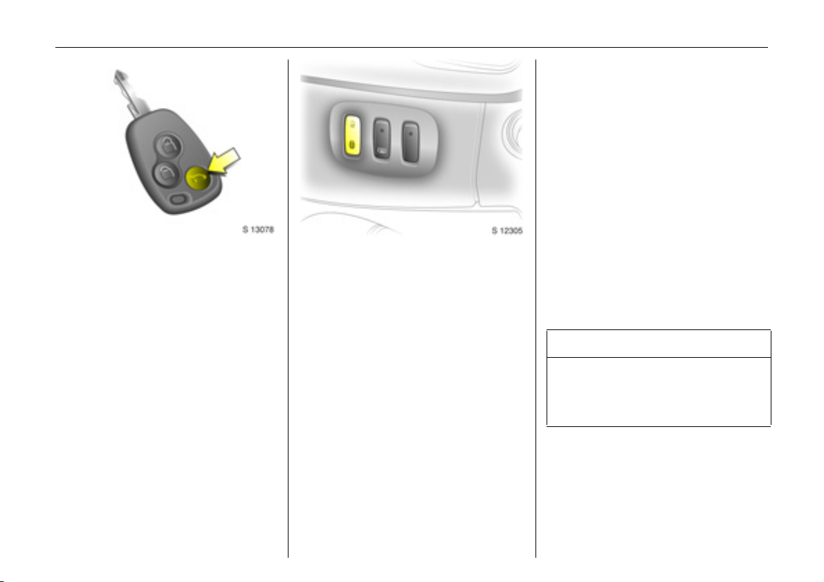
Unlocking the vehicle:
Direct remote control unit 3
towa rds vehicle, press button c,
pull door handle
The doors are unlocked.
To unlock mechanically: insert key and turn
in driver’s door lock, pull door handle.
To lock doors from inside, press central
lock ing switch 3 located on the lower part
of the instrument panel.
6 Door locking and unlocking see page 17,
child safety locks - see page 18,
electronic im mobiliser - see page 18,
radio frequency rem ote control 3 see page 19,
central locking system 3 - see page 21,
mechanical a nti-theft locking system -
see page 23,
Vauxhall alarm system 3 - see page 24.
Seat adjustment:
Pull handle, slide seat,
relea se hand le, allow sea t to
audibly latch into position
Never a djust the driver’s seat while driving.
It could move in an uncontrolled manner
when the handle ha s been pulled.
6 Seat position – see page 32.
9 Wa rning
Important: Do not sit nearer tha n
10 in ches (25 cm) from th e steering
wheel, to permit safe airbag deployment.
Page 7
In brief 3
A djusting the sea t b ack re st:
Pull release lever
Move seat backrest to suit seating position,
it will lock in position when the lever is
released.
6 Seat position – see page 32.
Adjusting the lumbar support 3:
Turn handwheel
Ad just lumbar support to suit personal
re q u ir em e n t s.
Do not lean on seat backrest whilst
adjusting it.
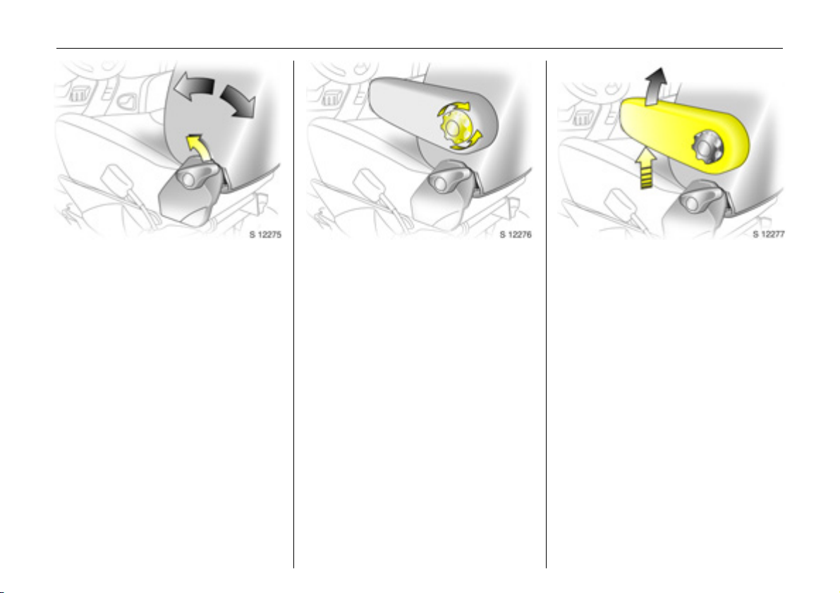
Adjusting armrest support 3:
Adjust armrest support to suit personal
requirements.
z Raise armrest in increments to desired
he ig ht .
z To reposition, fully ra ise armrest before
low ering.
Page 8
In b rief4
Adjusting seat height:
Pull lever at side of seat
Pull lever and remove body weight from
seat to raise it or press down on seat with
body weight to lower it.
6 Seat position – see page 32.
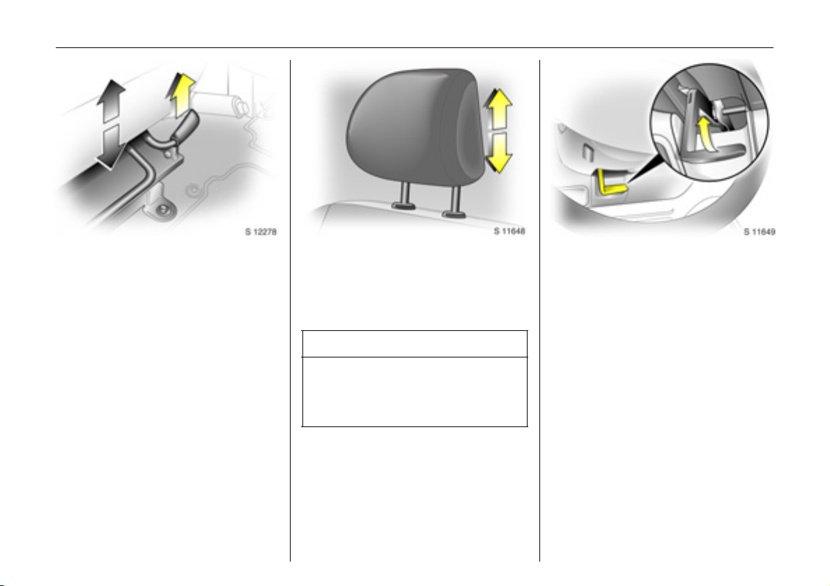
Adjusting head restraint height:
Hold firmly and adjust h eight,
then release
6 Head restraint position – see page 32,
further information, removal – se e page 33.
9 Warning
Disregard of these instructions may lead
to injuries or endanger life. Vehicle
passengers must be informed
accordingly.
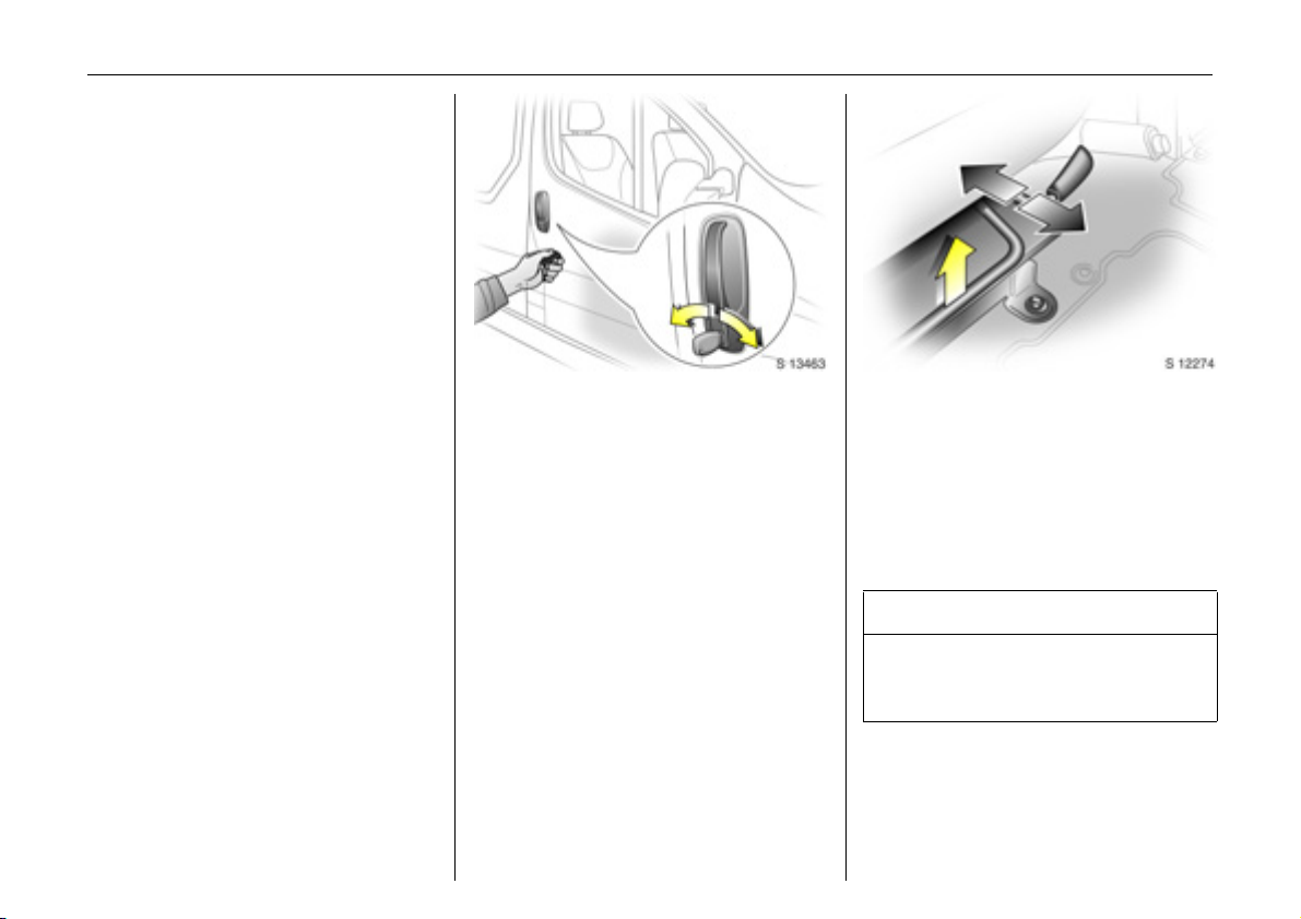
Steering wh eel adjustment:
Adjust position
Adjust the steering wheel only when the
vehicle is stationary .
Move the unlocking lever upwards, adjust
the wheel to the desired position, then
release the lever.
Push the lever firmly downwards to ensure
that the steering wheel is locked in position.
6 Airbag systems - see page 47.
Page 9
In brief 5
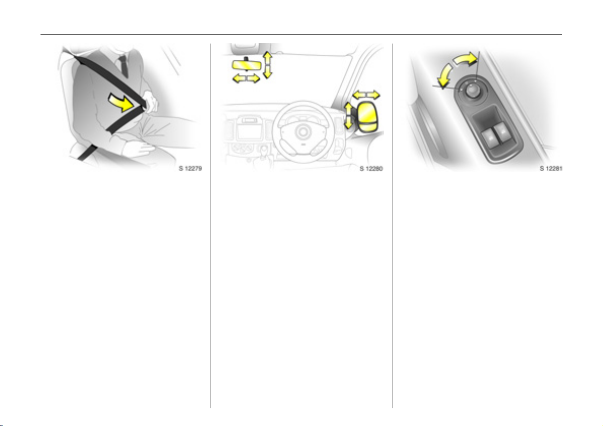
Fitting seat b elt:
Draw sea t belt smoothly from
inertia reel, guide over shoulder
and engage in buckle
The belt must not be twisted at any point.
The lap belt must lie snugly against the
body. The backrest must not be tilted back
too far (recommended max imum tilting
angle approx. 25°).
To release belt, press red button on belt
buckle.
6 Seat belts – see pages 36 to 40,
airbag systems – see page 47,
seat position – see page 32.
Adjust inte rior 3 and exterior
mirrors:
Swivel to appropriate position
Move lever on underside of interior mirror
housing to reduce dazz le at night.
6 Mirrors - see page 26.
Electrically adju stable exterior
mirrors 3:
Four-way switch in door panel
Tu rn switch to left or right: four-way switch
operates corresponding mirror.
6 Mirrors - see page 26.
Page 10
6In brief
Page 11

In brief 7
Page
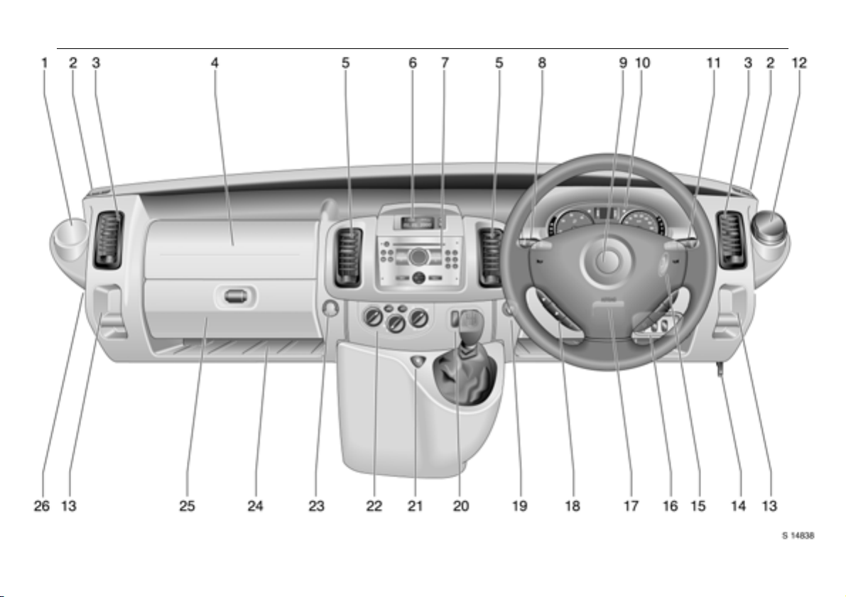
1 Drink holder ...... ......... ......... ......... ...... 57
2 Door window de froster v en t........... .. 84
3 Side air v en ts ......... ......... ........ ......... ..8 4
4 Front pa ssenger’s airbag 3 ....... 47, 51
5 Centre air v ents ......... ..... ........ ......... ..8 3
6 Triple Information Display 3 ...... ...... 68
Colour Information Display 3 .... ...... 70
7 Infotainment system 3.. ........ ......... ..81
Electronic tachograph 3 ....... ......... ..8 2
8 Parking lights, headlight flash,
front fog lig hts, fog tail light,
dipped and main beam ......76, 77, 7 8
Turn signal lights... .... ..... ............. .... .. 78
Pa ge
9 Driv er’s airbag .... ......... ......... ......... .. 47
Horn ............. ..... ......... ........ ......... ..... .. 11
10 Instruments.. ..... .... ......... ......... ......... .. 59
11 Win dscree n wiper
and wash sy ste m ......... .............. 74, 75
Rear door and tailgate window
wiper a nd wash system 3 ..... ......... .. 75
Trip computer 3............ .... ......... ..... .. 65
12 Ashtray ... .... ..... .... ......... .... ..... ........... 57
13 Coin tray
14 Bonnet release ..... ..... .... .... ......... ..... 1 2 6
15 Starter switch ....... ..... ........ ......... ......... 9
16 Head lig ht range adjustment ......... .. 79
17 Steering wheel adjustm en t ....... ..... .... 4
Plus
ESP®
(Electronic S tab ility Programme) ..108
Pa rk ing distance sensors 3 ....... ..... 109
3
Page
18 Steering wheel mounted
remote control 3 ..... .... ......... ..... .... ... 81
19 Cigarette lighte r....... .... ..... ......... .... ... 5 8
20 Central locking 3 ..... ......... ......... ....... 22
Heated rear w indows 3,
heated exterior mirrors 3 . ......... ....... 89
Easytronic w inter and laden
programm es 3 ......... .... ......... ..... . 93 , 94
21 Haz ard warning....... .... ......... ...... 23, 78
22 Heating and v entilation system .. ... 84
Air conditioning system 3......... .... ... 87
Rear air conditioning system 3 .... ... 88
23 Utility hook
24 Storage tray
25 Glove compartment
26 Fusebox .. ......... ......... ......... .... ......... . 13 7
Page 12

In b rief8
Control indicators
Ü Not used
9 Headlight dipped b ea m:
see pages 10, 59, 76.
P Hea dligh t main beam ,
he ad light fl ash :
see pages 10, 59, 76.
r Fog t ail lig ht:
see pages 10, 59, 78.
> Front fog lights 3 :
see pages 10, 59, 78.
u Anti-lock Brake System (ABS):
see pages 59, 112.
8 Di esel par ticle filt er 3:
see pages 60, 106.
F Not used
Pl u s
ESP®
v
Pro g r amm e) 3:
see pages 60, 108.
Engine oil life monitor 3 :
F
see pages 60, 68, 107.
(Electron ic S tabil ity
O Turn signal lights:
see pages 10, 60, 78.
C Stop e ngin e:
see page 60.
o Electronic im mobiliser:
see pages 18, 60.
A Service / Engine electronics 3:
see page 60.
Preheating / Fuel filter / Engine
D
electronics 3:
see pages 14, 60.
Fuel level:
Y
see pages 61, 102, 164, 170.
E Engine stop:
see page 61.
p Alternat or:
see page 61.
I Engine oil press ure:
see page 61.
R Brake system:
see page s 61, 111, 156.
Airbag systems, belt tensioners:
v
see pages 37, 47, 61.
Front passenger airbag
H
deactivation 3:
see pages 51, 61.
Not used
X
Door open 3:
U
see page 62.
U Not used
Z Exhaust emissions 3:
see page s 62, 104.
Not used
B
Easytronic 3
Lade n programme:
kg
see pages 60, 94.
T Footb rake ap plication:
see pages 60, 91.
W Transmission el ectronics:
see pages 60, 96.
A Automat ic mode:
see pages 60, 92.
V Wi nter prog ra m me :
see pages 60, 93.
Page 13
In brief 9
Starter switch:
Diesel engines
St = Ignition off
A = Steering unlocked, ignition off
M = Ignition on: preheating
(see page 1 4)
D = Start (tra nsmission in neutral)
Petrol engines
St = Ignition off
A = Steering unlocked, ignition off
M = Ignition on
D = St a r t ( t r an sm i ss ion in ne u t ra l)
6 Starting - see page 14,
ele ctronic immobiliser - see page 18,
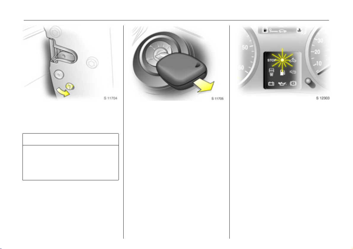
parking the vehicle - see page 16.
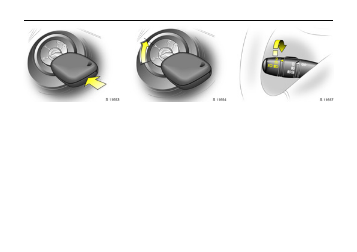
Releasing steering column lock:
Move steering wheel slightly and
turn key to position ‘A ’
6 Starting - see page 14,
electronic im mobiliser - see page 18,
parking the vehicle - see page 16.
Light switch:
7 =Off
0
9 P = Dipped or main
=Parking lights
beam
6 Headlig ht warning device - see page 74,
further information - see page 76,
automatic dip ped beam activation 3 see page 77,
hea dlight ra nge adju s tmen t - s e e pag e 79 ,
headlights when driving abroad -
see page 80,
daytime running lights 3 - see page 76.
Page 14
In b rief10
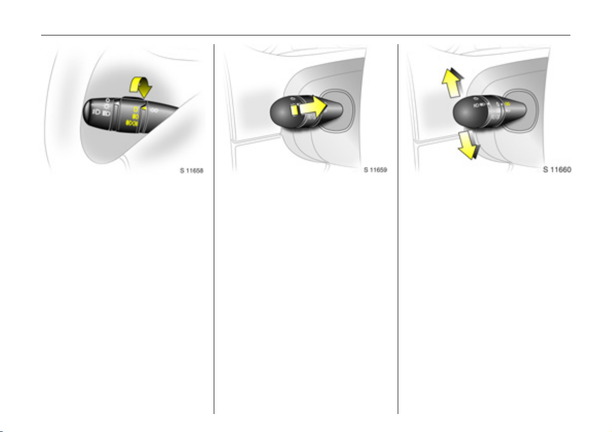
Fog lights:
7 =Off
> =On
(front fog lig hts 3
only)
>r =On
(front fog lig hts 3
and fog tail light)
6 Fog tail light, front fog lights see page 78.
Headlight flash, main beam and
dipp ed be am:
Pull stalk towards steering wheel
6 Further information - see pag e 77.
Turn sign al lights:
Stalk in rest pos ition
Upwards = Right turn
Do wn wa rds = L e ft t urn
6 For ope ration of the turn signal lights
when towing - see pages 60, 118,
turn signal lig hts - see page 78.
Page 15
In brief 11
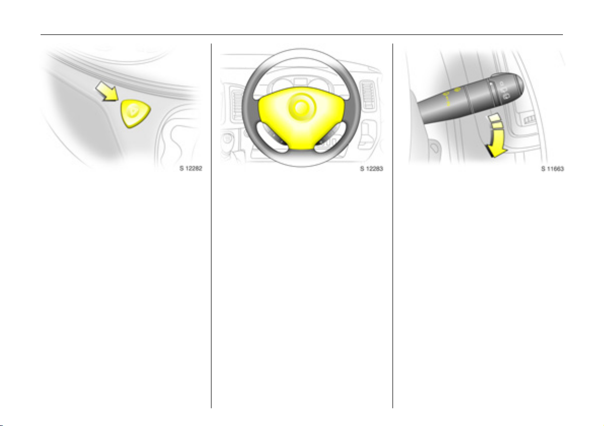
Hazard warning lights:
On = Press button ¨
Off = Press button ¨ ag ain
6 Further inform ation - see pages 23, 78.
Horn:
Pre ss an y pa rt of the stee ring wheel centre
to activate the horn.
6 Airbag systems – see page 47,
steering whee l mounted remote control 3 -
see page 81.
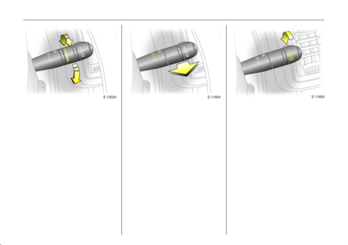
Windscreen wiper:
Move stalk downwards
KKKK =Timed interval wipe
1 =Slow
2 =Fast
Return the stalk to its original p osition to
turn off.
6 Further information - see pages 74, 15 7,
143.
Page 16
In b rief12
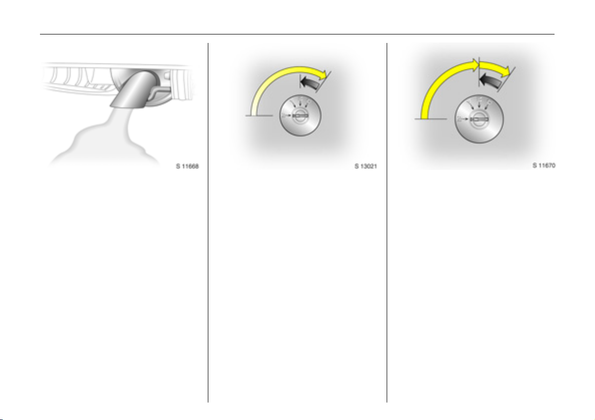
Automatic wiping with
rain sensor 3:
Move stalk downwards
KKKK = Autom atic wiping
with rain sensor
Adjust sen sitivity:
Rotate a djuster ring
Less sensitive = Rotate adjuster
forwa rds
More sensitive = Rotate adjuster
backwards
The rain sensor detects the amount of
water on the win dscre en and automatically
regulates the windscreen wiper frequency.
6 Further information - see pages 75, 143,
158.
Windscreen wash system:
Pull stalk towards steering wheel
Short pull
The wiper operates for one cycle.
Long p ull
Wash fluid is sprayed onto the windscreen,
at the same time the wiper is operated for
four cy cles.
6 Further information - see pag es 75, 159.
Rea r d oor a nd tailgate wind ow
wash wipe system 3:
Rotate switch
0=Off
e =Wiper
f =Wash
6 Further information - see pages 75, 158,
159.
Page 17
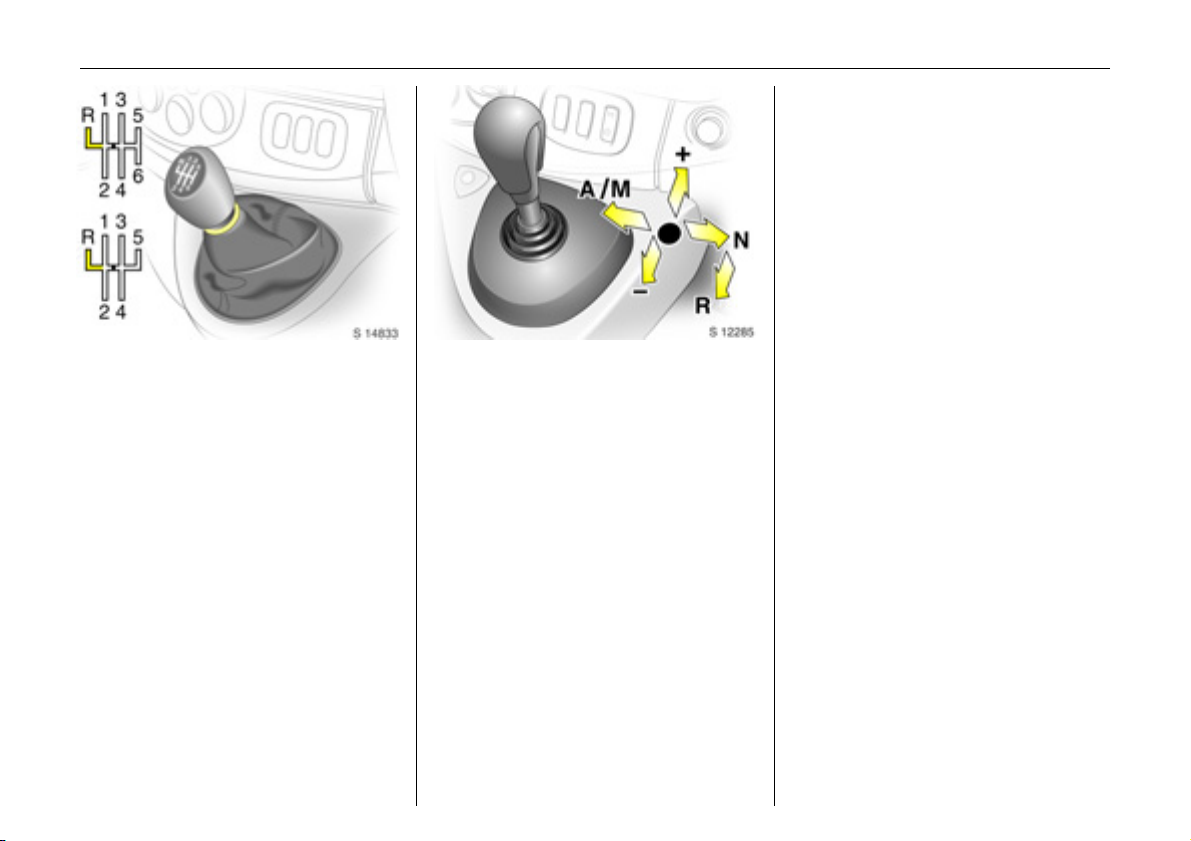
Manual transmission:
o =Neutral
1 to 5/6 = 1st to 5th or 6th 3
gear
R=Reverse gear
When shifting up from 4th to 5th gear,
pressure must be exerted towards the right
at the beginning of the shift operation.
When shifting from 5th to 4th gea r, do not
exert any forc e towards the left.
Reverse gear: with vehicle stationary,
depress clutch pedal, pull up collar and
move ge arshift lever to the left against
resistance.
If the gear does not engage : with lever in
neutral, re lease clutch pedal and depress
again, then repeat gear selection.
Easy tronic 3:
N=Neutral
o = Centre position
- = Shift to lower gea r
+ = Shift to high er gear
A/M = Switch between
Automatic and
Manual m ode
R=Reverse
The selector lever must be moved in the
appropriate direction as far as it will go.
Upon release, it automatically returns to
the centre position. Pay heed to the
gear / mode indicator in the transmission
display.
6 Further information - see pag e 91.
In brief 13
Before starting-off, check:
z Tyre pressures and condition.
z Engine oil level a nd fluid levels in engine
compartment (see pages 150 to 153).
z All windows, mirrors, exterior lig hting
and number plates are fre e from dirt,
snow and ice a nd are operational.
z Objects are securely located and will not
be thrown forwards in the event of
sudden braking.
z Seats, seat belts and mirrors are
correctly a djusted.
z Brake operation.
Page 18
In b rief14
Exhaust gases are poisonous
Exhaust gases contain carbon m onoxide,
which is extremely poisonous but has no
odour or colour.
Therefore, never inhale exhaust gases, and
never run the engine in an enclosed space.
You should also avoid driving with the
doors open, as exhaust gases could enter
the passenger compartment.
6 Exhaust gases - see page 107.
Starting, petrol engines:
Transmission in neutral,
depress clutch peda l 3,
do not accelerate,
turn key toposition D
The increased engine speed automatically
returns to normal idling speed as the
engine temperature rises.
6 Electronic immobiliser - see page 18,
further inform ation - see pages 97, 99, 101.
Starting, diesel engines:
Tran smissi on in neutral,
depress clutch pedal 3,
do not accelerate,
turn key to position M,
wait until preheating control
indicator D extinguishes1),
turn key to position D
6 Electronic immobiliser - see page 18,
engine preheating 3 - see page 60,
diesel fuel system 3 - se e page 125,
further information - see pag es 97, 99, 101.
1)
Preh eatin g system sw itches on only if outside
tem perature is low.
Page 19
In brief 15
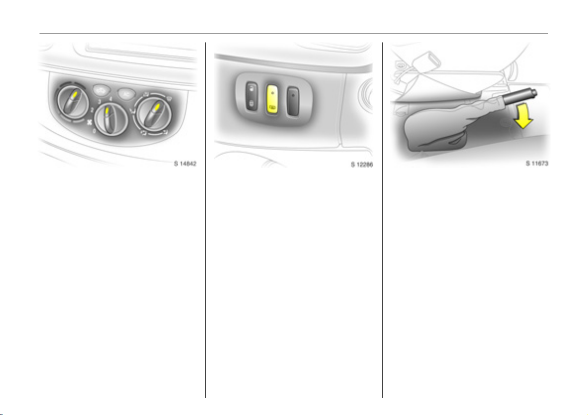
Drying misted-up or iced-up
windows:
Set temperature rotary knob
to red,
set fan to position 4,
set air di stribution to V
Close centre air vents; open side air vents
and dire ct them towards the doo r windows.
6 Heating and ventilation system see page 84,
air conditioning system 3 - see page 87.
Heated rear windows 3,
heated exterio r mirrors 3
Press Ü =On
Press Ü again = Off
6 Further information - see pag e 89.
To release th e handbrake:
Raise lever slightly,
press release button,
lower lever fully
6 Handbrake - see page 112.
Page 20

In b rief16
Parking the vehicle:
z Apply handbrake firmly without p ressing
the release button, and a pply as firmly
as possible on slopes.
z Switch engine off by turning ignition key
to p o sitio n " St". Remove ign ition key and
turn steering wheel until lock is felt to
engage (anti-theft protection).
z If the vehicle is park ed on a flat surface
or an uphill incline, with manual
transmission engage first gear or with
Eas ytro nic 3 move the selector le ver to
the centre position before switching off
the ignition. On an uphill incline, also
turn the fro nt wheels away from th e kerb.
z If the vehicle is park ed on a downhill
incline, with manual transmission or
Eas ytro nic 3 engage reverse gear before
switching off the ignition. Also turn the
front wheels towards the kerb.
z Lock doors and load compartment with
key in lock or button e or G on remote
control 3.
z To arm the Vauxhall alarm system 3 ,
press button e once, a nd to activate the
mechanical anti-theft locking system,
press b utton e tw ice.
Advice when parkin g:
z Do not park vehicle on easily ignitable
surfaces as the hot exhaust system
temperatures could cause the surface to
ignite.
z Close windows.
z The engine cooling fans may run after
th e engine has be en s witch ed off –
see page 97.
6 Further information - se e pages 18, 97,
radio frequency rem ote control 3 -
see page 19,
central locking system 3 - see page 21,
Vauxhall ala rm system 3 - see page 24.
That was a brief overview of the
most imp o r t ant in forma tio n fo r
your first drive in your Vivaro.
Your vehicle has still more
instruments and controls,
possibly also o ptional
equipment.
The rema in ing ch apt er s of the
Owner’s Manual contain
impo rtant information on
opera tion, safety and
maintenance as well as a
com plete index.
Page 21

Locks, doors, windows 17
Locks, doors, windows
Re placem ent ke ys ... ..... ......... ........ ..... 17
Door locking and unlocking.. ........ ..... 17
Lock cylinders ...... .... ......... ......... ......... 17
Ca r Pass 3 ....... ......... ..... .... ............. ..... 17
Child s afe ty lock .. .... ......... ......... ......... 18
Electronic immobiliser....... ..... ........ ..... 18
Radio frequency remote control 3.... 19
Central locking syste m 3. ..... ........ ..... 21
Mechanical anti-theft locking system 23
Vauxhall alarm system 3. ..... .... ......... 24
Sliding side doors 3. ......... ..... .... ......... 25
Rear doors 3... ......... ..... .... ............. ..... 25
Tailgate 3 ............ .... ..... ............. .... ..... 26
Mirrors. ..... ............. .... ..... ......... .... .... ..... 26
Window s.. .... .... ..... ......... .... ..... ............. 28
Sun visors.. .... ............. ..... .... ............. ..... 29
Replacement keys
The key is a constituent of the electronic
immobiliser. Ordering keys fr om a Vau xhall
Authorised Repairer guarantees problemfree operation of the electronic
immobiliser. Keep spare key accessible in a
safe place.
Locks - see page 146.
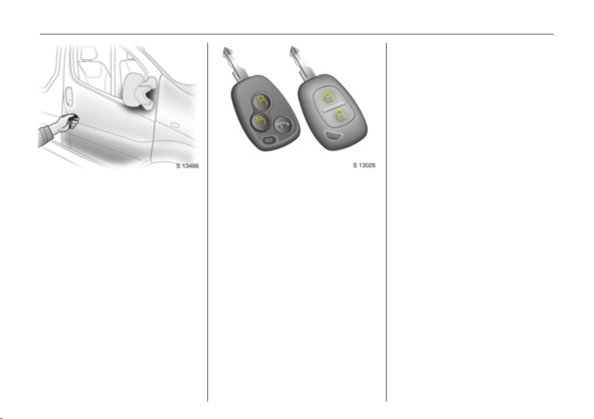
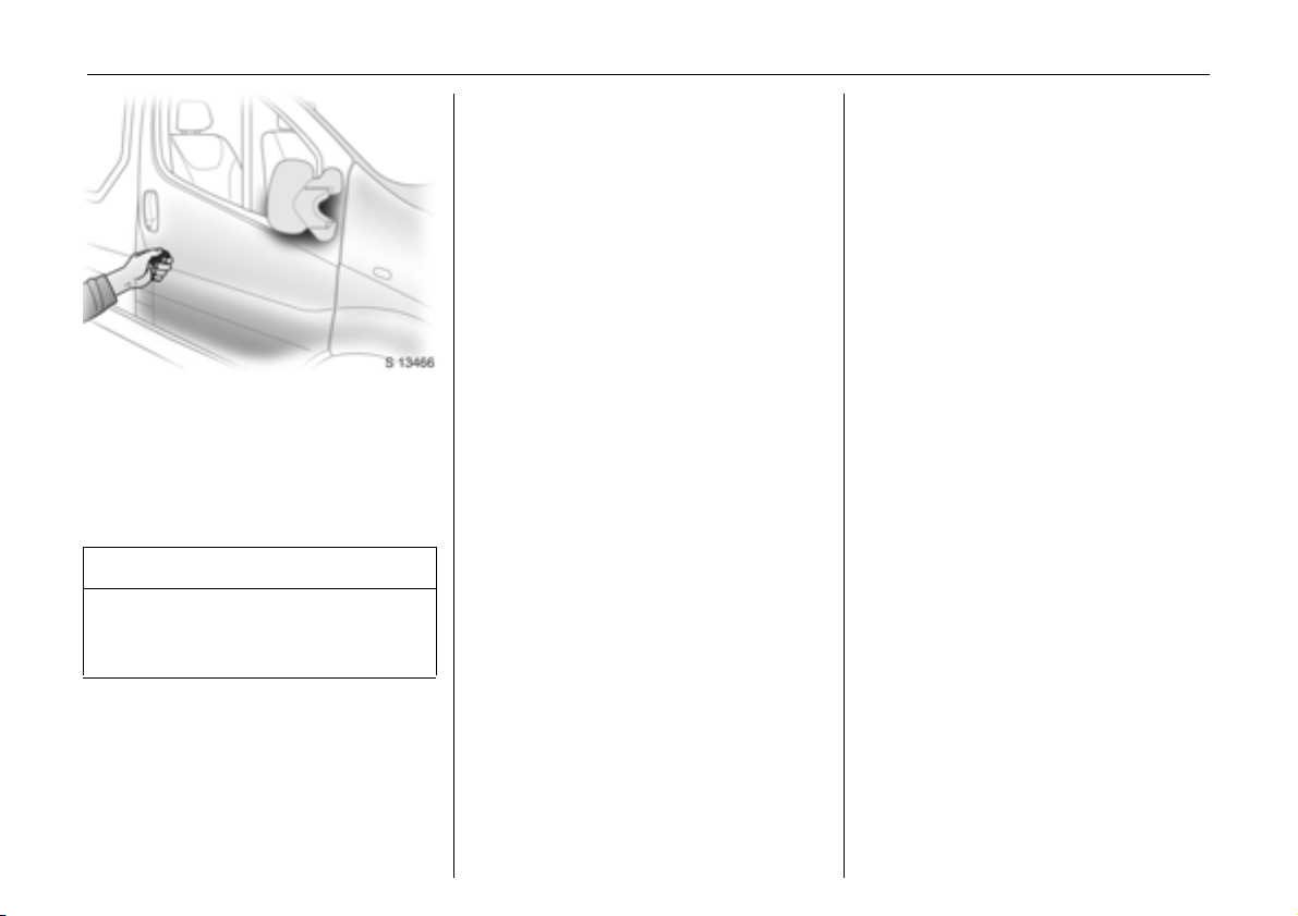
Door locking and unlocking
From outside:
Pull outside handle to open the front door.
Radio frequency remote control 3 -
see page 19,
central locking system 3 - see page 21,
mechanical a nti-theft locking system see page 23.
Fro m ins ide:
Pull the inside lever to open the front door.
The door can be locked or unlocked by
pushing / pulling the interior lock button 3
or using the central locking switch 3 -
see p age 22.
To prevent the driver from being
inad vertently locked out, the front doors
cannot be locked when they are open.
The tailgate can be opened by pushing
down the tailgate interior release 3.
Lock cylinders
Designed to free-wheel if they are
forcefully rotated without the correct key or
if the correct key is not fully inserted.
To reset, turn cylinder with the correct key
unt il its s lot is v ertical, remove key a nd then
re-insert it. If the cylinder still free-wheels,
turn the key through 180° and repeat
operation.
Car Pass 3
Th e Car P ass contains all o f the vehicle’s
data and should therefore not be kept in
the vehicle.
Hav e y our Ca r P as s to ha nd w h en
consulting a Vauxhall Authorised Repairer.
Page 22
Locks, doors, windows18
C hil d saf ety lo ck
The child safety lock for the sliding side
door 3 is located on its rearward fa cing
edge.
9 Wa rning
Use the child safety lock whenever
children are oc cup ying the rear seats 3.
Disregard may lead to injuries or
endanger life. Vehicle passengers must
be informed accordingly.
To engage, turn knob from the vertical
position: anticlockwise for right-hand side
door or clockwise for left-hand side door.
Door cannot then be opened from inside.
Electronic immobiliser
The s ys tem ch ecks wh ether the v ehicle may
be started using the key that has been
inserted. If the key is recog nised as
"authorised" the vehicle can be started.
The check is carried out via a transponder
hous ed in th e ke y.
The electronic immobiliser is automatically
activated when the key is removed from
the starter switch.
The electronic immobiliser is automatically
activated when the key is removed from
the starter switch and also if the key is left
in the starter switch wh en th e engine is
turned off. Reinsert the key to start the
engine.
C ontrol indic ator for im mobiliser
The control indicator illuminates when the
ignition is switched on then extinguishes.
If the control indicator flashes rapidly after
the ignition is switched on, there is a fault in
the immobiliser system.
z Turn ignition off and remove key,
z wait approx. 2 seconds,
z then repeat starting procedure.
If the control indicator fails to e xtinguish,
try to start the engine using the spare key.
Obtain assistance from a workshop.
Not e
The immobiliser does not lock the doors.
Therefore, after leaving the vehicle, always
lock it and switch on the Vauxhall alarm
system 3.
Page 23
Locks, doors, windows 19
C entra l lockin g system 3
see page 21.
Mechanic al anti -theft locki ng system
see page 23.
Vauxhall alarm system 3
see page 24.
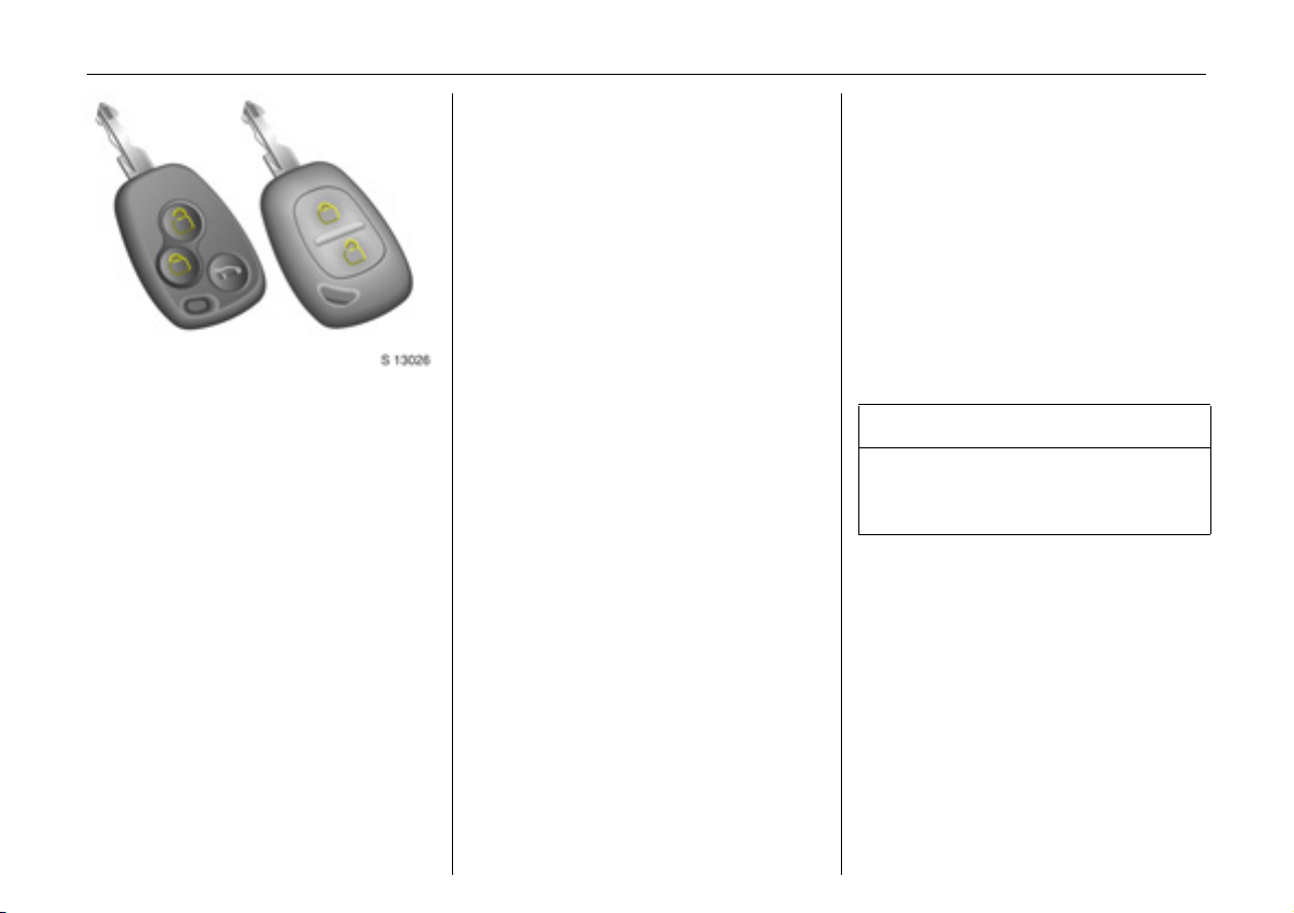
Radio frequen cy remote c ontrol 3
The remote control is used to operate the
central locking system 3.
Dep ending on model, the vehicle may use
a remote control with two or three buttons
(selective door locking).
The remote control has a range of approx.
5 metres. This range can be affected by
outside influences. Aim the remote control
at the vehicle to operate.
For your convenience, we recommend that
the central locking system is alway s
op erate d using the remote control unit.
Treat the remote control unit with care; it
should be protected against moisture and
should not be operated unnecessarily.
Page 24
Locks, doors, windows20
Note
If the central locking system 3 cannot be
operated with the remote control, this may
be due to the follow ing reasons:
z The remote control is out of range.
z The battery voltage of the remote
control is too low. Change the battery in
the remote control unit.
z The remote control has been operated
too many tim e s in succe ssi o n outsid e the
vehicle’s reception range (e.g. at too
great a distance from the vehicle).
The remote control must b e
reprogrammed, we recomme nd you
consult a workshop.
z Inte rference fro m high er p ow er radio
waves from other sources.
Lock or unlock the doors manually using
the key or central locking switch 3.
Manual locking does not operate the
central locking system. Have cause of fault
remedied by a workshop.
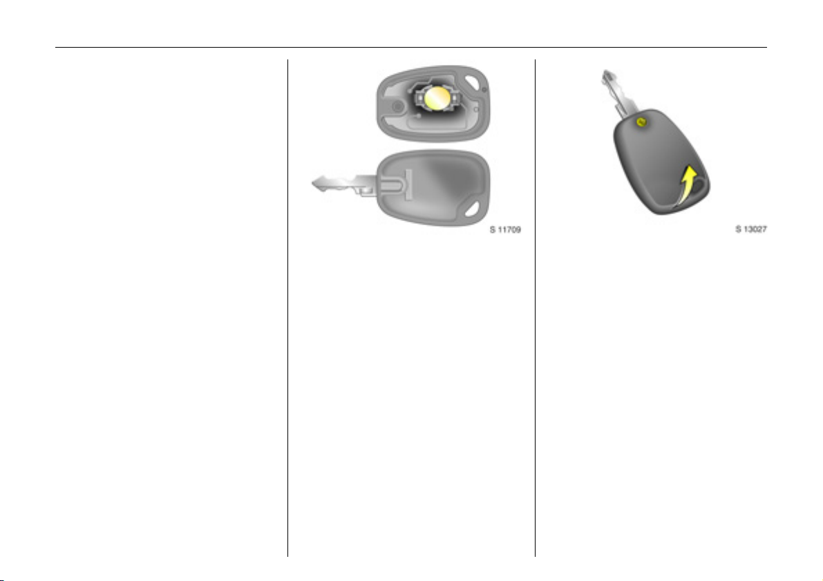
Changing the battery in re mote control
unit
Replace the battery in accord ance with the
Servic e Booklet or when the range of the
remote control starts to become reduced.
Tw o function remote control unit:
Open the battery compartment by
inserting a coin into the slot and twisting.
Ensure the new battery is installed
correctly.
Replace the cover a nd press until it is fully
engaged.
Sele cti ve door lock ing rem ote co nt rol u nit :
Open the battery compartment by
removing the screw on the rear cover, then
inserting a coin into the slot and twisting.
Ensure the new battery is installed
correctly .
Replace the cover and press until it is fully
engaged, then replace and secure screw.
Make sure that you dispose of old batteries
in accordance with environmental
protection regulations.
Page 25
Locks, doors, windows 21
Cen tral locking system 3
For front, side and rear doors 3, tailgate 3
and tank flap 3.
With selective door locking 3 , the
passenger com partment and rear load
compartment are loc ked and unlock ed
separately.
To unloc k - two function remote cont rol:
Press button c on remote control unit:
z Haz ard warning lights flash once.
z Doors are unlocked.
To unloc k - selectiv e d oor locking:
Press button c on remote control unit:
z Haz ard warning lights flash once.
z Doors of the passenger com partment
only are unlocked.
To lock - tw o func tion remote control:
Press button e on remote control unit:
z Hazard warning lights flash twice.
z Doors are locked.
To lock - s elective door l ocking:
Press button e on remote control unit:
z Hazard warning lights flash twice.
z Passenger compartment doors only are
loc ked.
Always ensure tha t the side door 3 ,
tailgate 3 or rear doors 3 are prope rly
closed before locking the vehicle with the
remote control.
9 Wa rning
For safety reasons, the vehicle cannot be
loc ked if the ignition key is in the starter
swi tch .
Manually locking or unlocking a door with
the key does not operate the central
locking system.
For manual operation of the tank flap -
see page 103.
Page 26
Locks, doors, windows22
Rear load compa rtme nt do ors / tailg ate selective door locking
To unlock:
Press button G on remote control unit.
The rear load com partment doors /
tailgate are unlocked.
If no door is opened within approx.
30 seco nd s after the v ehicle has be en
unlocked via the remote control, the vehicle
is relocked automatically.
To lock:
Press button G on remote control unit.
The rear load com partment doors /
tailgate are locked.
Cen tral l oc king sw itch 3
Use the c entral locking switch to lock or
unlock the doors from inside the vehicle.
Pre ss e on the switch to lock or U on t h e
switch to unlock.
Autom atic locking 3
The central locking system can be
activated to automatically lock the doors
as soon as a speed of approx.
4 mph (6 km/h) is reached.
To activate
With the ignition switched on, press e on
the central locking switch and hold for
approx. 5 seconds, until audible
confirmation is heard.
To deactivate
With the ignition switched on, press U on
the central locking switch and hold for
approx. 5 seconds, until audible
confirmation is heard.
Unlock ing the doo r
The doors are unlock ed by opening any
door from insid e the vehicle or by
operating the central locking sw itch.
9 Wa rning
If a rear door is opened, it will
autom atically be relocked when the
vehicle reaches a speed of approx.
4 mph (6 km/ h).
Page 27

Locks, doors, windows 23
Fault
In the event of a fault, e.g. automatic
locking doesn’t take place, ensure all the
doors have be en proper ly closed . Che ck to
ensure that the automatic locking function
has not been deactivated inadvertently. If
this is the case, switch the ignition off and
on again and reactivate the system as
described previously.
If the automat ic loc king fu nctio n still fails to
operate, we recommend that you seek the
assistance of a workshop.
9 Wa rning
If you decide on having the system active
(with the doors closed) while driving, it
may become difficult for those assisting
you in gaining access to your vehicle in
the ev ent of an emerge ncy.
Slam door lock s 3
For certain Van models1) th e s l id ing si d e
door and rear door locks are isolated for
added security.
Whilst the front doors are locked and
unlocked using the remote control key in
the normal way, the sliding side door and
re ar d oo r can on l y be op ened b y m a n ual
operation of the vehicle key.
Mechanical anti-theft locking
system
To lock:
All doors must be closed; press button e on
the remote control unit 3 again within
10 seconds after locking. Hazard warning
lights flash 5 times.
-orTurn k ey in driver's door lock towards front
of vehicle again within 10 seconds after
locking, then turn it back to the vertica l
position and remove.
Interior lock buttons 3 on all doors are
positioned such that doors cannot be
opened.
9 Wa rning
Do not use the system if there are people
in the vehicle! The doors cannot b e
unlocked from inside.
Importa nt:
When the ha zard warning lights or parking
lights are on, the mechanical anti-theft
locking system will not be activated.
1)
Not available with mechanical anti-theft
locking system.
Page 28
Locks, doors, windows24
To unlock:
Press button c on remote control unit 3.
Hazard warning lights flash once.
-orTurn key in driver's door lock toward s rear
of vehicle, then turn it back to the vertical
position and remove.
9 Wa rning
Unlocking is not possible in any other
way, so ke ep spare key to hand in a safe
place!
Vauxhall alarm system 3
The system monitors:
z Front and side doors.
z Rear doors or tailg ate 3 , bonnet.
z Passenger compartment.
z Starter switc h.
z Siren power supply 3.
The remote control unit 3 is used to
op erate the anti-theft alarm system.
To activate
All doors must be fully closed:
Press button e on the remote control;
the turn signal lights flash twice .
If the turn signal lights do not flash on
activation, this ma y indicate that a door or
the bonnet is not fully closed .
To deactivate
Press button c on the remote control;
the turn signal lights flash once.
If the alarm has been triggered, the turn
signal lights will not flash upon
deactivation.
When un lockin g the v ehicle us ing the key ,
the alarm will sound: to deactivate, insert
the key and switch on the ignition.
Not e
The anti-theft alarm system cannot be
deactivated in any other way, so keep a
spare key in a safe place.
Alarm
During a switch-on phase, the sensors can
trigger a maximum of 10 times1).
The alarm takes the form of:
z an acoustic signal
(horn, 25 seconds)
and
z a visual sig nal1)
(turn signal lights, 25 seconds).
1)
Varies from c oun try to country on a ccount of
national regu lation s.
Page 29
Passenger compartment monitoring
When the anti-theft alarm is activated, the
system automatica lly monitors the inside
of the v ehicle for m ovem ent.
To disable the passenger compartment
monitoring, (for exam ple if an a nimal is to
be left in the vehicle):
z Press and hold button e on the remote
control.
z An audible beep will sound to confirm
that the passenger c ompartment
monit oring func tio n is dis abled .
The disable monitoring function will remain
until the alarm is deactivated or the doors
unlocked.
Alar m bac k-up syst em 3
The alarm system has a battery back-up
siren unit whic h, in the event of its power
supply being disconnected or
disconnection of the vehicle battery, will
sound for approx. 5 minutes on its inte rnal
batteries.
If the vehicle battery has to be
disconnected it will be necessary to
deactivate the alarm system.
To stop the siren if activated, reconnect the
vehic le batte ry and press button c on
remote control unit.
Sl iding s ide doo r s 3
Open the door by pulling the outsid e
ha ndle, or by pulling the interior lever to
the rear, then sliding the door ba ckwards.
To close the door, slide it fully forwards and
ensure it is fully closed.
The door can be locked or unlocked with
the remote control 3, the ce ntral locking
swi tch 3 or by the interior lock switch.
Ensure the side door is closed before
driving the vehicle.
Locks, doors, windows 25
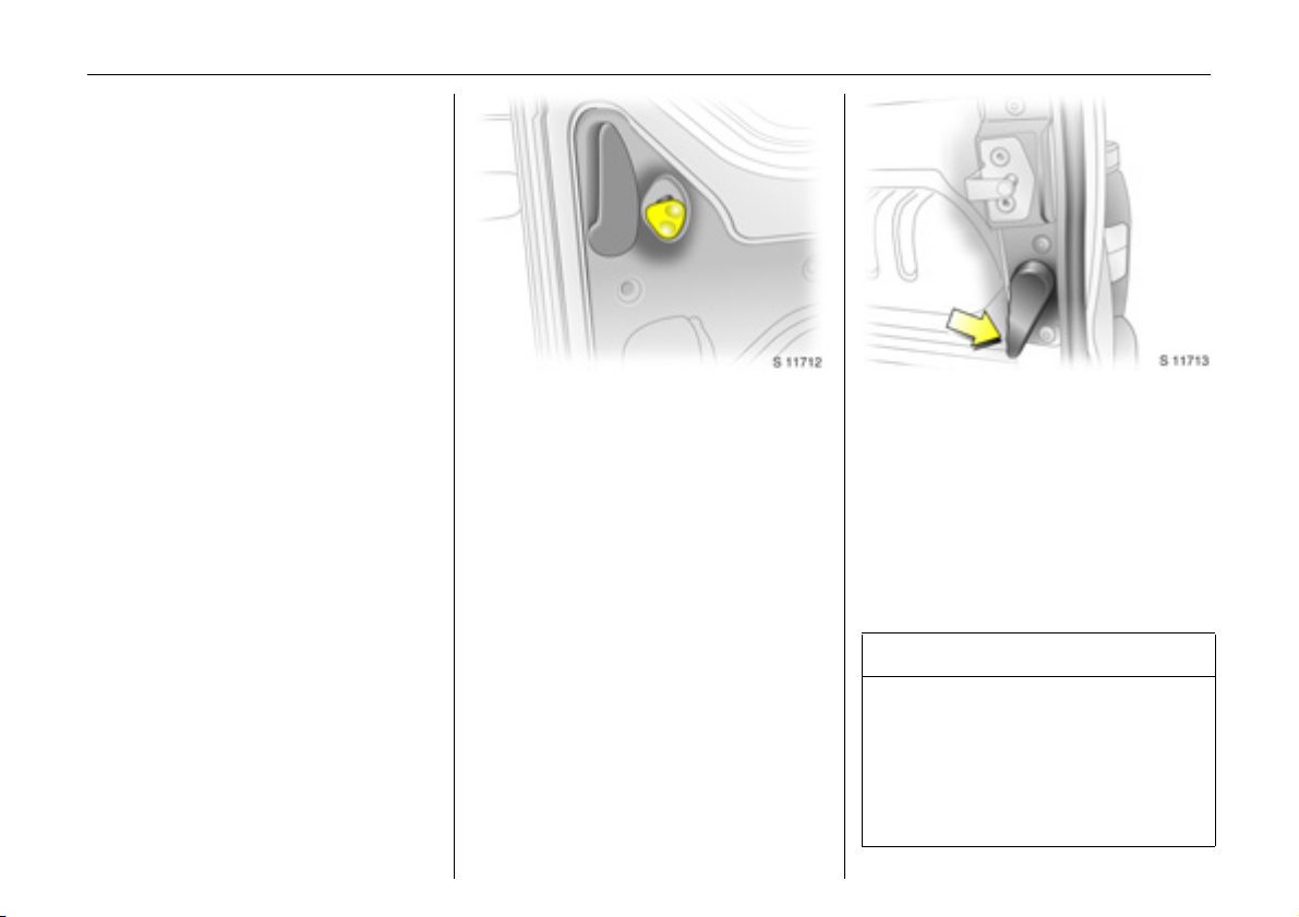
Rea r d oors 3
The doors can be locked or unlocked with
the remote control 3 , the central locking
switch 3, or the ke y 3.
To open the left-hand rear door, pull the
outside handle. The door is opened from
insid e the vehicle by pulling the interior
handle.
The right-hand rear door is released using
the lever (arrowed).
9 Wa rning
The rear lights may be obscured if the
rear doors are open and the vehicle is
parked on the roadside. You should
make other road users aware of your
vehicle, by using a warning tria ngle or
other eq uipm ent specifie d by your
country’s road traffic regulations.
Page 30
Locks, doors, windows26
Th e doors are retained in the 90º pos ition
by locking sta ys.
To open the doors to 180º or further 3, pull
the door release handles and swing open
to the desired p osition.
9 Wa rning
Ensure ex tended open ing doo rs 3 are
secured when fully opened.
Opened doors may slam closed due to
the force of the wind!
Always close the right-hand door before
the left-ha nd door.
Tailgate 3
To open: press button and lift tailgate to
fully op en po s i t i on .
In very cold climates, the opening
assistance provided by the tailga te
hy draulic struts may be reduce d.
The tailgate can be locked or unlocked
with the remote control 3 or the central
lock ing switch 3.
9 Warning
Ensur e there is adeq uate clearan ce both
above (at least 2.15 m) and behind whe n
opening tailga te.
Close tailgate using the interior strap.
Ensure tailgate is fully closed.
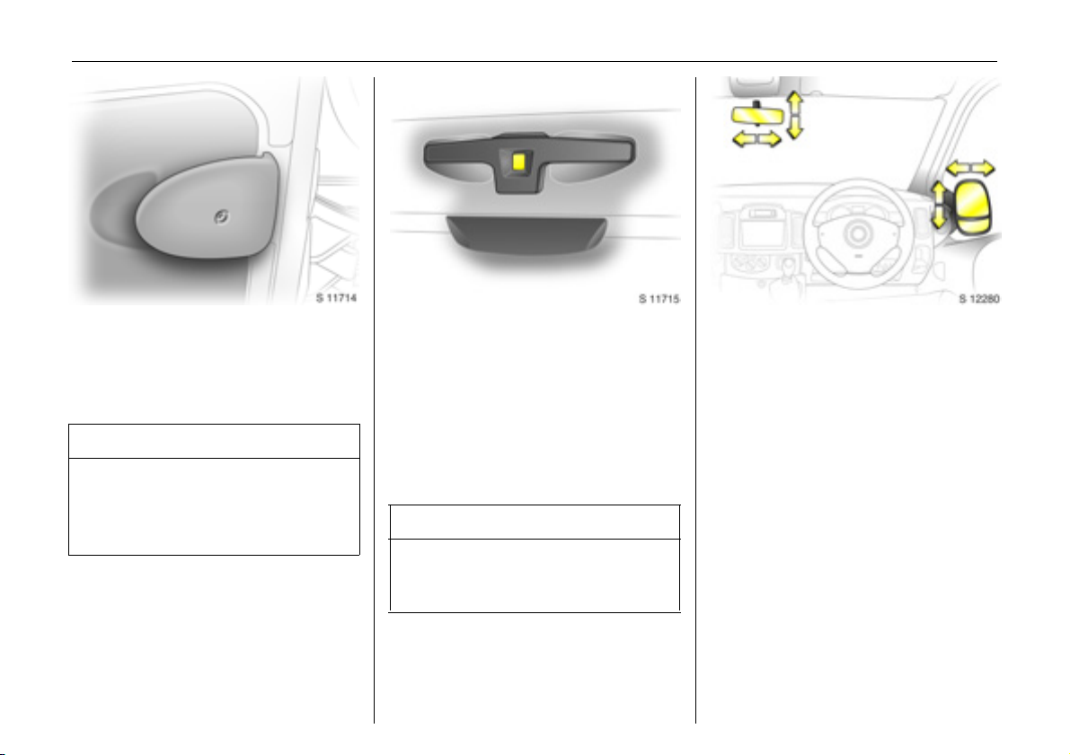
Mirrors
Interior 3 and exterior mirrors
To adjust mirrors, swivel to approp riate
position.
Move lever on underside of interior mirror
housing to reduce dazzle at night.
Take care when driving with interior mirror
adjusted for night vision. Rear view may be
slightly distorte d in this position.
Page 31

Locks, doors, windows 27
Aspherica l exte rior m irror
The aspherically curved mirror glass
increases the field of view. Estimating the
distance away from vehicles following you
is only p ossible to a limited extent because
of slight distortion.
Elec trical ly ad justable exter ior mirror s 3 :
Adjust mirrors using switch located in
driver’s door.
Operational with the ig nition on or off.
Turn switch to left:
Switch ope rates le ft-hand m irror.
Turn switch to right:
Switch operates right-hand mirror.
Switch in c entral position:
Mirror adjustm ent is off.
The lower aspherical mirrors are not
adjusta ble.
For the safety of pedestrians, the exterior
mirrors will swing out of their normal
mounting position in the event of an
accident-like impact.
Page 32

Locks, doors, windows28
Windows
9 Wa rning
Care must be taken when op erating the
elec trically operate d windows . There is a
risk of injury, pa rticularly for children, and
a danger tha t articles could be come
trap ped. Vehicle passengers must be
informed accordingly.
Make sure tha t all vehicle occupants
know how to operate the windows
correctly.
Keep a close watch on the windows when
closing them. Ensure that nothing
becomes trapped in them as they move.
Before leaving the vehicle, remove the
ignition key in order to prevent
unauthorized operation; risk of injury.
Door windows
The door windows can be operated with
the crank.
Electrically operated door w indows 3
With the ignition switched on, operate the
driver’s window using the switch located in
th e driver’s doo r.
To open the window, push the top of the
switch and to close, pull the top of the
switch. The window stops when the switch
is released.
Autom atic oper ation 3
With the ignition switched on, briefly push
or pull the switch to fully open or close the
driver’s window. Briefly push or pull the
switch aga in to stop the window durin g this
operation.
Page 33

Locks, doors, windows 29
Su nvisors
The sunvisors are padded and can be
swung up, down and to the side, for
protec tion o f the driver and pas se n ger
against glare .
With the ignition switched on, the front
passenger’s window is similarly operated
by a switch in the front passenger’s door or
the respective switch in the driver’s door.
Slidi ng side window s 3
To open, pull up catch and slide open.
To close, pull up catch and slide window
until catch e ngage s.
Note: during window opening or closing ,
keep the catch raised to allow the glass
sufficient clearance.
Page 34

Seats, interior30
Seats, interior
Fro nt sea ts ...... ..... ......... ......... ........ ..... 3 0
He ad re strain ts ........ ......... ......... ......... 3 2
Rear seats 3 ......... ......... .... ..... .... ......... 33
Three -stage restraint system ........ ..... 3 6
Three -point se at belts ............... .... ..... 36
Be lt tensioners. ..... ............. ..... .... ......... 3 7
Using the be lts .................. ..... ........ ..... 39
Child restraint systems 3 . ..... .... ......... 41
Airbag system s ........ ......... ......... ......... 47
Front passe nger airbag deactivation 3 51
Load compartment net 3..... .... .... ..... 54
Load compartment cover 3 . .... ......... 54
As htray .... ........ ..... .... .............. .... .... ..... 57
Drink holders ........ .... ......... ......... ......... 57
Warning triangle ¨ 3, First-aid kit +3 58
Power outlets .. ..... ......... ......... ........ ..... 5 8
Front sea ts
9 Warning
Never adjust seats while driving, as they
could move uncontrollably.
Important: Do not sit nearer than
10 inches (25 cm) from the steering
wheel, to permit safe airbag deployment.
Adjust seat longitudinally 3:
To adjust, pull the handle on the front seat,
slide the seat and release the handle.
Ad justing front seat b ackrests
To adjust, pull re lease lever, move seat
backrest to suit seating position and lock in
position when the lever is released.
Do not lean on seat backrest whilst
adjusting it.
Page 35

Seats, interior 31
Adjusting the lumba r support 3
To adjust, turn the handwheel whilst
relieving the load on the bac krest.
Adjust lumb ar support to suit personal
requirements.
Adjusting armrest support 3:
Ad just armrest support to suit personal
re q u ir em e n t s.
z Raise armrest in increments to desired
height.
z To reposition, fully raise armrest before
lowering.
Ad ju stin g seat h eight 3
To adjust, pull le ver at side of seat.
Pull lever and remove body weight from
seat to raise it or press down on seat with
body we ig ht to lowe r it.
Page 36

Seats, interior32
Seat position
Adjust driver’s seat such that with the
driver sitting upright the steering wheel is
held in the area of its upper spokes with the
driver’s arms slightly bent.
The seat backrests must not be tilted too
far back (recomm ended maxim um tilting
angle approx. 25°).
9 Wa rning
Dis reg ard can lead to inju rie s wh ich could
be fatal. Vehicle pa ssenge rs m us t be
informed accordingly.
Head restraints
Adjusting head restraint height, hold firmly
and adjust he ight, then release.
Do not a ttach objects or components that
are not approved for the Viva ro, to the
head restraints. These affect the protective
effect of the head restraints and can be
propelled through the vehicle in an
uncontrolle d m anner if the driv er brakes
hard or an accident occurs.
Head res tra int position
The centre of the head restraint should be
at eye level.
Adjust to hig hest position if this is not
possible for extremely tall people, and
adjust to lowest position for extrem ely
small people.
9 Wa rning
Disregard ca n lead to injuries which c ould
be fatal. Vehicle passengers must b e
informed accordingly.
Page 37

Seats, interior 33
Head re straint remova l
To remove the head restraints, pull lock tab
and pull the restraint upwards.
Stow head re straints securely in load
compartment. Do not drive with head
restraints removed if the seat is occupied.
Rear seats 3
On some model variants, the rea r
passenger compartm ent offers storage in
the seat trims.
To enable long items to be store d under
the seats, the centre rear seat trim cover 3
can be unclipped.
Th e lo ad cap acity can be increas ed f urth er
by folding or removing the rear seats 3.
When folding or removing the rear seat
ensure the armrests 3 are folded away in
their most upright position. Also remove
the lower seat trim side pock ets 3
disconnecting them from the locating clips.
Page 38

Seats, interior34
Rear s eat ac cess 3
To facilitate access to the rear seats, fold
the seat backrest forwards. If necessary
release the two-latch seat belt from its
buckles.
9 Wa rning
Ensure that the backrest returns to its
correct position a nd the seat belt buckles
engage securely - see page 39, 40.
Fold ing sea ts 3
On some m odel variants, the load area can
be increased by folding up the rear seats.
Remove the head restraints. Pull the side
ha ndle to re le as e th e bac kre st an d fold
forwards onto the seat cushion, if
ne cessary releasing the two-latch seat
belts from their buckles.
Release both locking bars at the rear base
of the seat by pulling back wards.
Lift and fold the seat assembly, until the
seat frame rests in place.
9 Warning
When folding the seat use caution beware of moving parts. Ensure the seat
is secure when completely folded.
To return the folding seat to the upright
position, support the seat assembly and
release the bar by pulling the bar directly
towards you. Gradually lower the seat
assembly, allowing the rear support legs to
fold down. Lower the seat complete ly,
ensuring the rear support legs are located,
and la tched. R aise the backrest, reinstall
head restraints and connect the seat belts.
9 Wa rning
When installing the seat, ensure that the
seat is properly located on the anchor
points and that the locking catches are
fully e ngaged , the backrest is returned to
the correct position and the seat belts are
engaged securely.
Page 39

Seats, interior 35
Removable rear seats 3
On some model variants, the load area can
be increased by removing the rear sea ts.
Release the seats by pressing down and
sliding forward the locking c atch located
on the left and right-hand seat m ountings.
With both catches ra ised, push the seat
unit towards the rear and release them
from the floor anchor p oints. The seat can
then be lifted out.
The seats must be removed through the
sliding door only.
9 Warning
Removable seats are heavy! Do not
attempt to remove without assistance.
When installing the seats, ensure that the
seats are properly locate d on the anchor
points and that the locking catches are
fully eng aged.
9 Wa rning
When re-installing seats always ensure
tha t the row with the folding access
se at B is positioned correctly in front of
the fixed seat row A.
If the seats are incorrectly positioned,
access for passengers is seriously
impeded. Disregard of these instructions
may endanger life.
Page 40

Seats, interior36
Three-stage restraint system
The system comprises
z Three-point seat belts.
z Belt tensioners on the front seats.
z Airbag sy ste ms for dr iver, front
passenger 3 and outboard rear seat
occ upa nt s 3 .
The three stages are activated in sequence
depending on the se riousness of the
accident:
z The automatic seat belt locking devices
prevent the belt strap from b eing pulled
out and thus ensure that the vehicle
occ upants are retained in their seats.
z The front seat belt buckles are pulled
downwards. As a result, the seat belts
are instantaneously tightened and the
occ upants are made awa re of the
deceleration of the vehicle at a very early
stage. This reduces stress placed on the
body.
z The airbag system is additionally
trigg ered in the event of a serious
accident involving a frontal impact and
for m s a sa fet y cu sh io n for t h e drive r an d
front passenger 3. The side airbag
sys tem 3 protects the occupants in the
front o f the vehicle in the event of side-o n
collisions.
9 Warning
The airbag system serves to supplement
the three-point seat b elts and belt
te ns ione rs. The s eat b elts mu st th e refore
always be worn. Disregard of these note s
can lead to injuries which may be fa tal.
Vehicle pas se ng er s must be in formed
accordingly.
Be sure to read the detailed descriptions
of all the restraint systems on the
following pages!
Three-point seat belts
The vehicle is equipped with three-point
seat belts with automatic retrac tors and
locking d evices, allowing freedom of body
movement although the spring tensioned
belts are alwa ys a snug fit.
The belt has a “vehicle sensitive retractor”
which is designed to lock during heavy
acceleration or deceleration in any
direction.
9 Wa rning
Alw ays wear your seat belt - and that
means also in urban traffic and when you
are a rear seat passenger. It can save
your life!
Pregnant women too must always wear a
se at be lt.
In the event of an accident, people not
wearing seat belts endanger the ir fellow
occupants and them selves.
Seat belts are designed to be used by only
one person at a time. They are only
suita ble for children aged up to 12 or
smaller than 150 cm if used in conjunction
with a child restraint.
Page 41

Seats, interior 37
Inspection of bel ts
Check all parts of the belt system
periodically for damag e and function.
Replace damaged comp onents. After an
accident, have the belts and triggered belt
tensioners replaced by a workshop.
Do not perform any alterations on the
be lts, the ir anchorages , the au tom atic
retractors or the belt buckles.
Make sure that belts are not dam aged or
trapped by sharp-edged objects.
Act uation o f be lt tensioners
The belt tensioners must be replaced after
activation by a workshop.
9 Wa rning
The belt tensioners are ope rational only
when the control indicator is unlit.
The seat belts remain fully operational
even when the belt tensioners have been
actuated.
Belt tensioners
The seat belt systems incorporate belt
tensioners. I n the event of a front or rear
impact the belt buckles are pulled
downw ards; the diagon al and la p be lts are
instantaneously tightened.
Page 42

Seats, interior38
Belt tensioner s c ont rol indic ator v
The seat belt tensioners are monitored
electronic ally toge the r with the airbag, an d
their operational readiness shown by the
control indicator in the instrument cluster.
When the ig nition is switched on, the
control indicator v illuminates, then
extinguishes. If it does not illuminate or if it
illuminates while driv ing, there is a fault in
the airbag system or the belt tensioners
(also see p age 50).
9 Wa rning
Have the cause of the fault remedied by
a workshop.
The system’s integrated self-diagnostics
allow s faults to be quickly remedied.
Imp or tan t
z Accessories not released for your v ehicle
type and other ob je cts must not be fixed
or placed within the action zone of the
belt tensioners as they ma y result in
injury if the belt tensioners are triggered.
z Do not make any modifications to the
components of the belt tensioners, as
this may result in unintended actuation
of the belt tensioners, rendering the
vehicle unroadworthy and causing
serious personal injury.
9 Warning
Imprope r handling (e.g. removal or
installation) can activate the belt
tensioners – risk of injury.
z The belt tensioner and airbag system
control electronics can be found in the
centre console area. In order to avoid
malfunctions, do not store magnetic
objects in this area.
z We recommend that you have the front
se ats remo ved by a w orkshop in the
event of actuation of the belt tensioners.
z When using the rear sea ts, ensure that
the front seat belt components are not
damaged by shoes or other objects.
Avoid dirt getting in the retractors.
z The belt tensioners only actuate once,
ind ic ated b y continuous illumination of
control indicator v in the instrument
cluster. Deployed belt tensioners must be
replaced by a workshop.
z When disp osin g of the v ehicle, plea se
observe the applicable safety
regulations. Please have the vehicle
disposed of by a company which reuses
vehicle parts.
Page 43

Seats, interior 39
Using the belts
Fitting the b elt
Pull the belt out evenly from the retractor
and guide it across the body, mak ing
certain that it is not twisted.
Insert the latch plate into the buckle. The
seat backrest must not be tilted back too
far; th e reco mme nded angle of inclination
is approx. 25°. The lap belt must not be
twisted and must fit snugly across the
body. Tension the belt frequently while
driving by tugging the diagonal pa rt of the
belt.
9 Warning
On pregnant w om en in particular the lap
belt must be positioned as low as
possible across the pelvis in order to
prevent pressure on the abdomen.
Bulk y clothing prevents the belt from fitting
properly. The belt must not rest against
ha rd or fragile objects in the pockets of
your clothing (e.g. ballpo int pens, keys,
spectacles) because these could cause
injury. Do not place any objects (e .g.
ha ndbags) between the belt and your
body.
Upp er anchorage point
height a djustment 3
z Do not adjust heig ht while driving,
z slide adjuster up or down to d esired
position.
Adjust height such that the belt passes
over the wearer’s shoulder and rests
against the shoulder. It must not pass over
the neck or upper arm.
Page 44

Seats, interior40
9 Wa rning
The seat b elt will not be e ffective in the
event of an accident if the lower latch is
not correctly fitted.
When releasing the seat belt, ensure that
the central buckle is always released
before the buckle on the side of the seat.
Alw ays remove the lower latch plate from
the outside buckle before removing seats
from the vehicle or to facilitate access to
the rear seats 3 - see page 33.
Remov ing the belt
To remove the belt, d epress the red button
on the buckle; the belt will retract
automatically.
Two-latc h belt 3
Before fitting the belt, first insert lower
latch plate in to the bu ckle on the ou tside of
the seat.
The belt can now be used in the same way
as a sta ndard seat belt.
Page 45

Seats, interior 41
Child restraint systems 3
Vauxhall child restraint systems are
designed specifically for your vehicle and
thus provide optimum safety for your child
in the event of impact. The use of a
Vauxhall child restraint system is therefore
recommended.
9 Wa rning
While using a child restraint system on
the front passenger’s seat, the airbag
sys t em s for t h e front pa ssen ge r’s sea t
must be deactivated (see page 51);
if not, the triggering of the front or side
airbag poses the risk of fatal injury to the
child.
This is especially the case if rearward-
fac ing child restraint systems are used on
the front p assen ge r ’s seat .
Selec ting the rig ht system
Your child should be transported facing
rearwards in the vehicle as long as
possible. It is appropriate to change the
system when the child’s head can no longer
be p rope rly s u pport ed at ey e he igh t. The
child’ s neck area is still very weak and in an
acciden t the y suffe r les s stress in the se miprone rearw ard position than when sitting
up rig ht .
Not e
z Children under 12 years or und er 150 cm
tall should only travel in an ap propria te
child restraint.
z Whe n transporting childre n, use the child
restraint systems suitable for the child's
weight.
z Ensure that the child restraint system to
be installed is c ompatible with the
vehicle type.
z The fabric cover of the Vauxhall c hild
restraint system can be wiped clean with
a damp cloth.
z Do not stick anything on the child
restraint systems and do not cover them
with any other materials.
z A child restraint system which has been
subjected to stress in an accide nt must
be replace d.
z Ensure that the mounting location of the
child restraint system within the vehicle is
correct.
z You sh o u ld a lso ob serve the instr u ctions
on installation and use supplied with the
child restraint system.
Page 46

Seats, interior42
The following Vauxhall child restraint
systems have been approved for
installation in your Vivaro:
Group, weight and age
1)
class
0
From birth - 10 kg,
0 - 10 months
0+
From birth - 13 kg,
0 - 2 years
I From 9 - 18 kg,
8 months - 4 years
II
from 15 - 25 kg,
3 years - 7 years
from 22 - 36 kg,
II I
6 years - 12 years
1)
We recommend the use of each system
until the child reaches the upper weight
li mi t .
Vauxhall
system
Baby Safe
Duo ISO FIX
Kid
If child restraint systems of other
manufacture are to be installed, ensure
that they conform to the appropriate
safety regulations.
9 Wa rning
Disregard of thes e ins tructions m ay lea d
to injuries or endanger life.
Th e country in w hich you ar e trav elling
may prohibit child restraint installation in
certain locations. Always observe local or
national regulations.
Page 47

Seats, interior 43
Front seats - all model variants
Group, weight and age class
Fa cin g
directi on
Single seat - front passenger
without
airbag
with airba g
- no side
airbag
0:
up t o 10 kg or approx. 10 months
0+:
up t o 13 kg or approx. 2 years
Rearward U U
I: 9 to 18 kg or approx. 8 months - 4 years Forward U U
II :
15 to 25 kg or approx. 3 - 7 years
II I:
22 to 36 kg or approx. 6 - 12 years
1)
If a djusta ble , ens ure seat is in it s r earmo st positi on. Make sur e v ehicle s eat b elt is as st raight as pos sibl e b etwe en sh oul der and upper anchorage point.
2)
Ensure the front passenger’s airbag system is deactivated when installing a child restraint in this position. See page 51.
U = Suitable for u niversal category child restraint system s fo r use in this mass gro up, in conjunction with three-point seat belt.
UF = Suitable for universal catego ry forward-facing child restraint system s fo r use in this mass gro up, in conjunction with three-point seat belt.
Forward U U
2)
2)
2)
X = Seat position not suitable for children of this mass gro up.
1)
with side
airbag
2)
U
2)
U
2)
U
Benc h seat - front passenger
w ithout airbag with airbag
centre outer centre outer
X
U
X U
UF U UF U
UF U UF U
9 Wa rning
While using a child restra int system on the front p assenger’s seat, the airbag systems for the front pa ssenger’s seat m ust be deac tivated
(see page 51); if not, the triggering of the front or side airbag poses the risk of fatal injury to the child.
This is especially the case if rearward-facing child restraint sy stems are used on the front passenger’s seat.
2)
2)
2)
Page 48

44 Seats, interior
Combi - rear seats
Group, weight and age class
0:
up to 10 kg or approx. 10 months
0+:
up to 13 kg or approx. 2 y ears
I: 9 to 18 kg or approx. 8 months - 4 years Forward
II :
15 to 25 kg or approx. 3 - 7 yea rs
II I:
22 to 36 kg or approx. 6 - 12 y ears
U = Suitable f or universal catego ry restraint systems for u se in this mass gr oup , in con junction with th ree-point seat belt.
L = Suitable only for s pecifically approved child restraints. Vauxhall has approved child restraint systems from th e ’Baby-safe’, ’D uo-ISOFIX’ a nd ’Kid’
ranges.
+ = S eat wi th ISOFIX mounting available. Wh en m ountin g ISOFIX, only IS OFIX c h ild restraint systems that h av e been a pproved for the vehicle may be used .
X = Seat position not suitable for children of this mass gro up.
Facing
direct ion
Rearward
Forward U
2nd row bench sea t 3rd row bench seat
Outer Centre Outer Centre
U
UU,+
U,+ XX
X
U
X
X
X
Page 49

Tour - rear s eats
Seats, interior 45
Group, weight and age class
0:
up to 10 kg or approx. 10 months
0+:
up to 13 kg or app rox. 2 years
I: 9 t o 18 kg or approx. 8 months - 4 years Forward
II :
15 to 25 kg or ap prox. 3 - 7 years
II I:
22 to 36 kg or ap prox. 6 - 12 years
U = Suitable for u niversal category child restraint system s fo r use in this mass gro up, in conjunction with three-point seat belt.
L = Suitable only for s pecifically approved child restraints. Vauxhall has approved child restraint systems from th e ’Baby-safe’, ’D uo-ISOFIX’ a nd ’Kid’
ranges.
+ = Seat w ith ISOFIX mounting a vailable. When moun ting ISOFIX, on ly ISOFIX child restraint systems that have been approved for the veh icle may be used.
X = Seat position not suitable for children of this mass gro up.
Faci ng
direction
Rearward
Forward U U X
2nd row benc h se at 3rd row bench se at
Outer Centre Outer Centre
U
U
U,+ XX
U,+ X
X
X
Page 50

46 Seats, interior
Double Cab - rear seats
Group, weight and age class
0:
up t o 10 kg or approx. 10 months
0+:
up t o 13 kg or approx. 2 years
I: 9 to 18 kg or approx. 8 months - 4 years Forward
II :
15 to 25 kg or approx. 3 - 7 years
II I:
22 to 36 kg or approx. 6 - 12 years
X = Seat position not suitable for children of this mass gro up.
Facing
direction
Rearward
Forward X
Rea r bench seat
Outer Centre
XX
XX
X
Page 51

Seats, interior 47
When triggered, the driver’s airbag a nd
front passeng er’s airbag 3 inflate in
milliseconds and form safety cushions for
th e driver a nd front pa ssenge r. The
forward mov ement of the driver and front
passenger is checked and the risk of
injuries to the upper body and head are
thereby substantially reduced.
z No impairment of view will occur,
because the airbags inflate and deflate
so q uick ly.
9 Wa rning
Airbag systems
Front airb ags
Th e front airbag s ys tem is identified by the
word “Airbag” on the steering wheel and
above the glov e c ompartment 3.
The front airbag system comprises:
z An airbag with an inflator in the steering
wheel, and a second one behind the trim
panel abov e the glove compartment 3.
z The control elec tronics with impact
se ns or.
z The airbag system control indicator v in
the in st r u me nt cluster .
z Front passenger airbag deactivation 3.
The front airb ag system is triggered:
z De pending on the severity of the
accident.
z Depending on the ty pe of impact.
z Within the range shown in illustration
S 11741.
z Inde pendently of the side airbag 3 and
curtain airbag systems 3.
Exa mples:
z Imp act against a non-yielding obstacle:
the front airbag is trigge red at low
vehicle spe ed.
z Imp act against a yielding obstacle (such
as another vehicle): the front airb ag is
only triggered at a higher vehicle speed.
The front airbag system provides
optimum protection when the seat,
backrest and head restraint are correctly
adjusted. Adjust the driver's seat
according to the occ upant's height such
tha t with the driver sitting upright, the
steering wheel is held in the area of its
upper spokes with the driver's arms
slightly bent. The front passenger’s seat
should be as far back as possible, with
the backrest upright. Do not place the
he ad, b o dy , ha nds or fe et o n th e co ve r of
the airbag system.
Do not place any objects in the area in
which the airbags inflate.
The three-point seat belt must be
correctly fitted (see page 39).
Page 52

Seats, interior48
The front airbag system will not be
triggered in the event of:
z The ignition being switched off.
z Minor frontal collisions.
z Accidents in which the vehic le overturns.
z Collisions involving a side or rear-impact
where it would not be of b enefit to the
occ upa nt s.
9 Wa rning
Seat belts must therefore always be worn.
The front airb ag system serves to
supplement the three-point seat belts. If
you do not wear your seat belt you risk
being seriously injured, or even thrown
from the ve h icle, in the event of an
accident.
The be lt he lps to ke ep y ou in the correct
seating position, in which the front airbag
system will provide you with effective
protection in the event of an accident.
Side airb ags 3
The side airb ags are mounted on the
outboard side s of the front se at backre sts
to protect the oc cupants in the event of a
se vere s ide-imp act.
The side airbag system comprises:
z An airbag with inflator in the back of the
driver's and front passenger's seat
respectively .
z The control electro n ics.
z Sid e-impact sensors.
z The airbag systems control indica tor v in
the instrument cluster.
The side airbag system will be triggered:
z Depending on the severity of the
accident,
z Depending on the type of impa ct.
z Within the range shown in illustration
S 11743.
z Independently of the front airbag
sy ste m.
Page 53

When triggered the side airbag inflates in
mi lli s econds a n d form s a sa fet y cu sh ion f o r
driver and/or front passenger in the
respective door area. The risk of injury to
the upper body in the event of a sideimpact is the reby substantially reduced.
9 Wa rning
The re m ust be no objects in the area in
which the airbag inflates or in the area
between the seat backrests and the
vehicle body. Do not place the hands or
arms on the covers of the airbag systems.
Important information - see page 52.
The three-point seat belt must be
correctly fitted - see page 39.
The side airbags will not be trigg ered in the
event of:
z The ignition being switched off,
z Frontal collisions.
z Ac cidents in which the vehicle overturns.
z Collisions involv ing a rear-im pact.
z Collisions involving a side-impact outside
the passenger cell.
Curtain airbag s 3
The curtain airbag system is identified by
the badge AIR BAG on the headlining trim.
The curtain airbag system comprises:
z An airbag w ith inflator in the roof frame
on the d riv er’s an d p assen ger’s side
respectively .
z The control electro n ics.
z T h e si de -impact s ens o rs.
z The airbag systems control indica tor v in
the instrument cluster.
Seats, interior 49
The curtain airbag system will be triggered:
z Depending on the severity of the
accident.
z Depending on the type of impa ct.
z Within the range shown in illustra tion
S 11743.
z Tog ether with the side airbag sy stem.
z Independently of the front airbag
sy ste m.
Page 54

Seats, interior50
When triggered the curtain airbag inflates
within milliseconds and provides a safety
barrier in the head area on the respective
side of the vehicle. This reduces the risk of
injury to the head considerably in the event
of a side-impact.
9 Wa rning
The re m ust be no objects in the area in
which the airbag inflates. Do not place
the hands or arms on the covers of the
airb ag systems. Important information –
see page 52.
The thre e-point seat belt must always be
correctly fitted – see page 39.
The curtain airbags will not be triggered in
the event of:
z The ignition being switched off.
z Frontal collisions.
z Ac cidents in which the vehicle overturns.
z Collisions involv ing a rear-im pact.
z Collisions involving a side-impact outside
the passenger cell.
9 Wa rning
Have the cause of the fault remedied by
a workshop.
The system's integral self-diagnosis facility
allows faults to b e quickly remedied.
Airbag control ind icator v
The front airb ag system, side airbag
sy ste m 3 and curtain airbag system 3 are
monitored electronically together with the
belt tensioners, and their operational
readiness shown by the control indicator v
in the instrument cluster. When the ignition
is switched on, the control indicator
illuminates then extinguishes. If it does not
illuminate, or if it illuminates while driving,
there is a fault in the airbag system s or the
belt tensioners.
The systems might not be triggered in the
event of an accident.
Page 55

Seats, interior 51
Front passenger airbag
deactivation 3
Front and side air bag sy ste ms must be
deactivated if a child restraint system is to
be mounted on the front passenger’s seat.
The belt tensioners as well as all airbag
systems for the driver’s seat remain active
when the front passenger seat’s airbag
systems are disengaged.
The switch for deactivating or activating
the airbag system is located on the front
passenger’s door.
The chosen setting remains activ e after the
ignition has been switched off. Control
indicator H for front passenger airbag
deactivation is located in the instrument
cluster.
To deactivate:
With the front passenger’s door open,
press switch in and rotate anticloc kwise to
the "OFF" position .
The airbag sy ste ms for th e f ront
passenger’s seat are now deactivated.
With the ignition switched on, the control
indicator H will remain illuminated to
indicate deactivation. It is now safe to
place a child restraint on the front
passenger’s seat.
Page 56

Seats, interior52
To activate:
Ensure the airbag systems for the front
passenger’s sea t are activated when a
passenger of a dult size occupies th e front
passenger’s seat.
With the front passenger’s door open,
press switch in and rotate clockwise to the
"ON" position. Front p assenger’s airbag
systems are now activated and will be
triggered in the event of an accident.
Upon switching the ignition on, control
indicator H will illuminate briefly and then
extinguish, indicating that the front
passenger’s airbag is active.
If control indicator H remains illuminated
in conjunc tion with control indicator v, this
indicates a fa ult within the system.
9 Wa rning
Have the cause of the fault remedied by
a workshop.
Imp or tan t
z Accessories not released for your v ehicle
type and other objects must not be
affixed or placed in the area in which the
airbags inflate, as they could cause
injury when the airbags are triggered.
z Do not place any objects between the
airbag systems and the v ehicle
occupants; risk of injury.
z Do not stick or place anything on the
stee ring wheel, instrume nt p anel, fro nt
seat backrests in the vicinity of the
airbags and seat areas or cov er them
with other materials.
z The airb ag systems and b elt tensioner
control electronics can be found in the
centre console area. In order to avoid
malfunctions, d o not store magnetic
objects in this area.
z Use only a dry cloth or Interior /
Upholstery Cleaner to clean the steering
wheel, instrument panel, front seat
backrests, roof frame and seat area of
the front passenger’s seat. Do not use
any aggressive cleaning agents.
z Only protective covers which are
approved for your Vivaro with side
airbag 3 may be fitted on the front
seats. W hen fitting the protective covers,
make sure that the airb ag units on the
outboard sides of the front seat
backrests are not covered.
z The airbag systems are triggered
ind ependently of each other depending
on the severity of the accident a nd the
type o f im pact. The side airbag s ystem 3
and the curtain airbag system 3 are
trig gered together.
z Each airbag can be triggered only once.
Once triggered, an airbag must be
replaced without dela y by a workshop.
z The speeds, directions of movement and
deformation properties of the vehicles,
and the properties of the obstacle
conc erned, determine the severity of the
accident and triggering of the airbags.
The degree of dama ge to your vehicle
and the resulting repair costs alone are
not indicativ e that the criteria for
trig gering of the sid e airbag 3 were met.
Page 57

Seats, interior 53
z Do not perform any modifications to the
com ponents of the airbag systems, as
this will render the vehicle unroadworthy.
9 Wa rning
The systems can be triggered ab ruptly
and cause injury if they are handled
im p r o p er l y.
z We recom mend hav ing the s teerin g
wheel, the instrument p anel, all panelling
parts, the door seals, the hand les and
the front seats re moved by a workshop
in the event of triggering of the airbags.
z When disposin g of the v ehicle, pleas e
ob serve the applicab le safety
regulations. Please have the vehicle
disposed of by com pany which reuses
vehicle parts.
9 Wa rning
Child restraint sy stems as well as other
heavy objects must never be carried on
the lap of passengers; risk of fatal injury.
9 Wa rning
While using a child restraint system on
the front passenger’s seat, the airbag
sy st e m s for the front passen ge r’s se at
must be deactivated; if not, the
trig gering of the front or side airbag
poses the risk of fatal injury to the child.
This is especially the case if rearwardfacing child restraint systems are used on
the front passenger’s seat.
The system for deactivating the front
passenger seat’s airbag systems is
indica ted a stick er on the side of the
instrument panel, visible when pa ssenger’s
door is open.
Page 58

Seats, interior54
Load c ompartment net 3
The load compartment net can b e fitted
behind the front or rear seats to separate
compartments when transporting luggage
or animals.
Installing (fro nt or rear pos ition)
Lift the covers to access the mountings,
insert the load compartm ent net rod into
the mounts a nd secure. Attac h the stra ps
to the lashing eyes behind the front seats;
or to the rings on the rear seat frame, then
tension the straps.
Removing
Tilt strap length adjuster upwards and
unhook strap.
9 Warning
Loose objects in the load compartme nt
should be secured safely.
Load compartment cover 3
To remove:
Lift cover and disconnect from the side
guides.
Not es on load ing
See page 56.
9 Wa rning
Do not place any heavy or sharp objects
on the cover.
Loose objects in the load compartment
should be secured safely.
Page 59

Seats, interior 55
z loa ds can then be secured in position
using lashing straps 3 attached to the
anchorage point.
The maximum load of each anchorage
point is 75 kg. To prevent the possibility of
exceeding this maxim um , th e use of
ratchet type lashing straps is to be
avoide d.
9 Wa rning
Loose objects in the load compartment
should be secured safely.
Lashing eyes
Lashing eyes are mounted in the load
compartment to enable loads to be
secured in position using lashing stra ps 3
or a luggage floor net 3.
The maximum force applied to the lashing
eyes should not exceed 5000 N at 30°.
Load anchorage ra ils 3
Load anchorage rails mounted in the load
compartment, provide adjustable
anchorage points for securing loads.
z Re lease centre pin of the anchorage
point, by pulling out against spring
tension,
z slide the anchorage p oint to the required
location,
z position the anchorage point directly
over the nearest suitable "locking hole",
z release the centre pin of the anchorage
point, ensuring the pin is located
correctly and the anchorage point is
securely locked,
Page 60

Seats, interior56
Note s on lo ad ing the vehicle
z Heavy objects in the load compartm ent
should be placed as far forwards as
possible. If objects are to be stacked, the
he avier objects should be placed a t the
bottom. Unsecured objects in the load
com partment would be thrown forwards
with great force in the event of heavy
braking, for example.
z Secure heavy objects with lashing
straps 3 attached to the lashing eyes.
If heavy loads slip when the vehicle is
braked heavily or driven around a bend,
the handling of the vehicle m ay change.
z Secure loose items in load compartment
using luggage floor net 3, to prev ent
sliding.
z When transporting objects in the load
com partment, fit loa d compartment
ne t 3 - see page 54.
z Close the load compartment cover 3, to
prevent the objects from being reflected
in t he rea r wi nd ow .
z If the rear seats a re not folded down 3 or
re m o ve d 3 when transporting objects in
the load compartment, they must be
engaged in their upright position see page 34.
z The warning triangle 3 and first-aid kit 3
should a lways be freely accessible.
z No objects should be placed on the load
compartm ent cover 3 or the instrument
panel. T hey are reflecte d in the g lass,
obstruct the driver’s view and will be
thrown through the vehicle in the event
of heavy braking, for example.
z No objects should be stored in any of the
airbag 3 inflation zones, as injuries may
be caused w hen the a irba g is triggere d.
z T h e lo ad m us t n ot o bs tr u ct t h e op era tio n
of the pedals, handbrak e and gearshift
lever, or hinder the freedom of
movement of the driver. Do not place
any unsecured objects in the interior.
z Bulky objects should not be transported
with the rear doors open or ajar,
otherwise poisonous exhaust fumes may
enter the vehicle. In addition, the number
plate is only distinguishable and
illuminated correctly if the doors are
closed.
z Weights, payload and roof load -
see page 166.
z Driv ing with a roof load (also see
page 97) increases the sensitivity of the
vehicle to crosswinds and has a
detrimenta l effec t on vehicle handling
owing to the higher centre of gravity of
the vehicle.
9 Wa rning
Disregard of these instructions may lead
to injuries or e ndanger life . Vehicle
pas se ngers must be in formed
accordingly.
Page 61

Seats, interior 57
Over-cab storage area 3
The total weight in this com partment must
not exceed 30 kg.
Ashtray
Removable to enable universal use for
driver or p assenge rs.
To be used only for ash and not for
combustible rubbish.
9 Warning
Disregard of these instructions may lead
to injuries or endanger life. Vehicle
passengers must be informed
accordingly.
To open: lift up the cover.
To empty: remove the ashtray from the
drink holder recess and empty.
Drink holders
To u s e drink holde rs, remove the ashtray
unit.
Page 62

Seats, interior58
Warning triangle ¨ 3,
First-aid kit+3
Your first-aid kit and w arning triangle can
be accommodated in the space under the
fro nt se ats.
9 Wa rning
Ensure it ems stowed unde r th e se ats a re
securely restrained.
Power outlets
Ciga ret te lighte r )
With ignition switched on, press in the
cigarette lighter. Heating up ceases once
element is glowing. Withdraw lighter.
Accessory socket
The soc ket for the cigarette lighter ca n be
us ed to conn ect ele ctrical acc essories when
the ignition is switched on.
An ad dit ional acce ssory s ocket 3 is loc ated
in the rear of the vehicle.
When the eng ine is not running, using these
accessory sockets will cause the batte ry to
be discharged.
The maximum power requirement of
electrical ac cessories must not exceed
120 watts.
Do not connect any current-delivering
accessories, e.g. electrical charging
devices or batteries.
Connected electrical accessories must
comply with the EC standard in terms of
electromagnetic compatibility
require ments laid down in DIN VDE 40 839,
otherwise vehicle malfunctions may occur.
The use of non-authorised accessories may
cause damage to the socket.
Page 63

Instruments, controls
Instru ments, controls 59
Control indicators .................. .... .... ..... 59
Instrume nt display... ..... ......... ........ ..... 62
Multi-fun ction display .. .... ......... ......... 64
Trip computer 3 .. .... ......... ..... .... .... ..... 65
Engine oil life monitor 3... ............. ..... 6 8
Triple Information Display 3 ............. 6 8
Outside temperature .... ......... .... .... ..... 69
Colour Information Display 3 ....... ..... 70
Warn ing buzzers.. .... ..... .... ......... .... ..... 74
Windscre en wiper .... ......... ......... ......... 74
Windscre en was h system ...... ........ ..... 75
Rear door and tailgate window wash
wi pe sy ste m 3 ... .... ..... ......... .... .... ..... 75
Control indicators
The control indica tors described here are
not present in all vehicles. The descriptions
however, apply to all instrument versions.
The colours of the control indicators mean:
z Red
z Y ellow
z Green
z Blue
Danger, important reminder,
Warning, information, fault,
Confirmation of activation,
Confirmation of activation.
Ü
Not used
9
Headlight dipped bea m
Illum inates in green when dipp ed b eam is
on - see pages 10, 76.
P
Headlight main beam, headlight fl ash
Illuminates in blue when m ain beam is on
and w he n headlight flash is operated -
see pages 10, 76.
r
Fog tai l light
Illuminates in yellow when the fog tail light
is switched on - see pages 10, 78.
>
Front fog li ghts 3
Illuminates in green when front fog lights
are switched on - see pages 10, 78.
u
Anti-lock Bra ke Syst em (ABS)
Control indicator illuminates in yellow see page 112.
Page 64

In struments, controls60
8
Die sel partic le fi lter 3
Illuminates in yellow when regeneration
of diesel particle filter is required -
see page 106.
F
Not used
v
Plus
ESP®
(Electr oni c Sta bility Program me )
Control indicator illuminates in yellow see page 108.
3
F
Engine oil life monit or 3
Control indicator illuminates in yellow in
transmission display - see pages 68, 107.
kg
Easytronic , La den program me 3
Illuminates in yellow in transmission display
wh en Lade n programme is enable d -
see page 94.
T
Easytronic , footbrake appl ication 3
Control indicator illuminates in yellow in
transmission display - see page 91.
W
Easytronic, transmission electronics 3
Illuminates in yellow briefly when ignition
is switched on. Illuminates in transmission
display w hen fault has occurred see page 96.
A
Easy tronic, A ut omatic mode 3
Illum inates in y ellow in tra nsmis sion d isplay
when Automatic mode is selected -
see page 92.
V
Easy tronic, W inter p rogramm e 3
Illum inates in y ellow in tra nsmis sion d isplay
wh en W inte r programm e is e nab led -
see page 93.
O
Turn sig nal lig hts
The corresponding control indicator
flashes in green when the turn signal light is
on.
Flashes rapidly: a turn signal bulb has
fa il e d.
An audible warning can be heard when the
turn signal lights are on. When towing a
caravan or trailer, the pitch of the audible
warning changes.
Turn signal lights - see pages 10, 78.
Bulb replacement - see page 140.
C
Stop e ngine
If control indicator C illuminates in red, in
conjunction with p, I, E or R, stop
engine immediately a nd consult a
work shop.
o
Electronic im mobiliser
If the control indicator flashes in red when
the ignition is on, there is a fault in the
im m ob iliser sy st e m; the en gine can no t b e
started - see page 18.
A
Service / Engine electronics 3
If control indicator A illuminates in yellow,
in conjunction with u or v, interrupt y our
journey. Consult a workshop.
D
Pre hea ting / F uel f i lte r / En gin e
electronics 3
Illuminates in yellow briefly during engine
preheating - see page 14.
If illuminated continuously it indicates:
z The pre se n ce of wa ter in th e diesel f uel
filter 3. Drain diesel fuel filter of residual
water - see page 154.
z An electronic system failure: consult a
workshop.
Page 65

Instru ments, controls 61
Y
Fuel level
If it illuminates in yellow:
fuel level low, fill up.
Never let the tank become empty !
With diesel engines, it is not possible to
start the engine after the tank has been run
empty. The fuel system must be bled first.
Further information - see pages 102, 164,
170.
E
Engine stop
Will illuminate in red in conjunction with C
engine if coolant temperature is too high.
Stop vehicle and consult a workshop.
p
Alternator
Illuminates in red when ig nition is switched
on. Extinguishes after engine is started.
If illuminated while driving:
Stop vehicle and switch off engine. The
battery is not being charged and the
engine cooling may be inte rrupted. The
brake servo unit may cease to be effective.
Interrupt your journey and check drive belt
condition and tensioning before
contacting a workshop.
I
Engine oil p ressure
Illum inates in red when ignition is switched
on. Extinguishes after a short period of
tim e. Can illuminate intermittently when
idling with hot engine; must extinguish
wh en e ngine spee d is increased.
If illum inated while driving:
Engine lubrication may be interrupted,
resulting in da mage to the engine and/or
lock ing of the driving w heels:
z Move out of the flow of traffic as quickly
as possible without impeding other
vehicles,
z Depress clutch,
z Move gearshift lever to neutral, or with
Easytronic 3 place selector lever in N,
z Sw itch off ignition (to position A).
Considerably greater force will be
required for braking and steering.
9 Warning
Do not rem ov e ke y until v e hicle has come
to a standstill, otherwise the steering
column loc k could engage unexpectedly.
Check engine oil level before consulting a
workshop. If the engine oil level is low, top
up using the specified engine oil - se e
pages 150, 164.
If the engine oil le vel is normal, hav e a
workshop che ck the vehicle’s lubric ating
sy ste m.
R
Brake system
Illuminates in red when ignition is switched
on if ha ndbra ke is applied an d/or f luid le vel
for brake hydraulics is too low.
9 Wa rning
If it illuminates when the handbrake is not
applied: stop vehicle ; interrupt y our
journey immediately. Consult a
workshop.
Further information - see pag es 111, 156.
v
Air b ag s yst e m s, bel t te ns ion ers
Control indicator illuminates in yellow see page s 37, 47.
H
Front pass enger airbag deact ivati on 3
Illuminates in yellow when the ignition is
switched on and remains illuminated when
the front passenger’s airbag has been
deactivated.
If control indicator H is illuminated in
conjunction with v or A, consult a
workshop.
Further information - see page 51.
Page 66

In struments, controls62
X
Not used.
U
Door open 3
Operational only when ignition is switched
on. Illuminates in red when d riv er’s door,
passenger’s door or side loading doors are
open.
U
Not used.
Z
Exhaust emissions 3
Illuminates in yellow when ignition is
switched on. Extinguishes shortly after
engine starts.
If it illuminates when the engine is running:
Fault in emi s sion control syste m. The
permitted emission limits may be
exceeded. Consult a workshop.
If it flashes when the engine is running:
For fau lt that can lead to destruction of the
catalytic conv erter, see page 104. Consult
a workshop imm ediately.
B
Not used
In strument disp la y
Tachometer
Making use of the tach om ete r helps to
sav e fuel; it indicates the engine spe ed in
revolutions per minute.
Warning zone on right: maximum
permissible engine speed exceeded;
danger to engine.
If possible, drive in each gear in the low
engine speed rang e (be tween approx.
2000 and 3000 rpm) and maintain an even
vehicle sp ee d.
Sp eedom eter
Indicates the vehicle speed.
Certain model variants feature a speed
regulator 3 1) which restricts the vehicle
maximum speed. As a visible indication of
this, a wa rning labe l is located on the
instrument panel.
1)
Depen ding o n driving environment (e.g . when
descendin g steep inclines), the veh icle speed
can exceed set limits. In such instances, it
rem ains the driver’s respons ibility to adhere to
the s pecific speed limits.
Page 67

Instru ments, controls 63
For physical reasons, the coolant
temperature gauge shows the coolant
temperature only if the coolant level is
adequate.
Fuel gauge
Display of fuel level:
Illumination of bars displays fuel level.
When fuel gauge indicates fue l supply is
low, fuel warning control indicator Y
illuminates = fill up. See page 102.
Never let tank become empty!
Coolant temperature gauge
Display of coolant temperature:
Bars illuminated
in lower area
Bars illuminated
up to cen t r al
area
Bars illuminated
in uppermost
zone or control
indicator E
illuminates 3
= Engin e o perating
temperature not y et
reached.
= Normal operating
temp erature.
= Temperature too
high. Stop vehicle,
sw itch off engine.
Danger to engine.
Chec k coolant level.
See p age 155.
Page 68

In struments, controls64
Multi-f u nction d i spla y
Transmission display 3
Display of the selected gear and mode with
Ea sy tronic.
N Neutral or idling position.
R Reverse gear.
A Automatic mode.
kg Laden programme.
V Winter prog ramme.
T Footbrake application.
W Transmission electronics.
Engine oil level display
The engine oil level d isplay is correct only if
the vehicle is parked on level g round with a
cold engine. The engine oil level display will
only be reset if the ignition has been
switched off for more than two minutes.
If "OIL" appe ars in the display, the engine
oil level may need topping up. To gain a
more accurate indication of the engine oil
level, press and hold the reset button - see
page 67.
The squares that a ppear in the display
indicate the engine oil level. As the engine
oil level diminishes, the sq ua res in the
display disappear and are re placed with
dashes.
A:Maximum level
B:Intermediate level
C: Minimum level = check and top up
engine oil
1)
Co ntrol indicator A illuminates if
engine oil level is too low.
To return to the norma l display, press the
reset button again.
Checking and topp ing up fluids see page 150.
1)
Page 69

Instru ments, controls 65
Elec tronic odom eter / c lock
In normal mode, the odometer and clock
are visib le.
The reset button is loca ted alongside the
speedometer. Press button once to d isplay
the trip odometer.
Press the button and hold; the display will
flash and after 1 second will reset to zero.
Press the button again to return the
odometer to normal m ode.
To adjust the clock:
With the display in normal mode, press and
hold the button, and the minutes reading
will begin to increase.
After the button is released, the clock will
continue to flash for a further 5 seconds to
enable further adjustments to be made.
Trip computer 3
In addition to the electronic odometer
functions, the trip comp uter can also
display additional monitored vehicle data,
including;
z Fuel used.
z Average consumption.
z Instantaneous consumption.
z Range.
z Distance travelled.
z Average speed.
Pr essing th e s election switch located on th e
end of the windscreen wash stalk will cycle
through these displays.
Fuel used
Displays the amount of fuel consumed
since the last reset.
The m easurement can be restarted at any
time – see "Reset trip compu ter
inform ation" on page 67.
Page 70

In struments, controls66
Averag e consum ption
Average consumption is displayed, taking
into consideration the dista nce travelled
and the fuel used since the last reset.
The m easurement can be restarted at any
time - see "Reset trip computer
information" on page 67.
Instantaneous consumption
The value is displayed after reaching a
speed of 15 mph (25 km/h).
Rang e
Th e ra ng e is calculate d from the c urre nt
conten ts of the fu el tank and the averag e
consum ption since the last reset see "Reset trip computer information" on
page 67.
The range will not be displayed if fuel level
control indicator Y is illuminated.
Page 71

Instru ments, controls 67
Dis tance tra velled
Displays the distance driven since the last
reset.
The m easurement can be restarted at any
time - see "Reset trip computer
information".
Average speed
The average speed is displayed, since the
la st rese t.
The me asurement can be restarted at any
tim e - see "Reset trip computer
information".
Stoppages in the journey with the ignition
off are not included in the calculations.
Reset trip compute r inform ation
To reset the trip computer, select one of its
functions then press the reset button.
The following trip computer inform ation
will be reset:
z Fuel used.
z Average consumption.
z Range.
z Distance travelled.
z Average speed.
Interr uption of power supply
If the power supply has been interrupted or
if the battery voltage has dropped too low,
the values store d in the trip computer will
be lost.
Page 72

In struments, controls68
Engine oil life monitor 3
Each time the ignition is switched on, the
remaining distance before the next engine
oil and filter cha nge is due may be shown
in the display for approx. 5 seconds.
Within 1800 miles (3000 km) of the next
engine oil chan ge be ing du e, the rema inin g
distance and control indicator F will
illuminate in red for approx. 30 seconds as
a reminder. Make an appointment with a
workshop for service work as soon as
possible .
Further information - see page 107.
Trip le In fo r m a tion Di s pl ay 3
Display for time, outside temperature,
ra dio / date.
When the ignition is off, the time, date and
outside temperature can be made to
appear for approx. 15 seconds by briefly
pressing one of the two buttons beside the
display.
Sett ing dat e a nd time
Switc h off radio. Press Ö and ; beside
display as follows:
Press Ö for approx. 2 seconds:
Day flashes
;:Set day
Ö:Month flashes
;:Set month
Ö:Year flashes
;:Set year
Ö:Hours flash
;: Set hours
Ö: Minutes flash
;: S et minutes
Ö: Clock starts at 0 seconds.
Page 73

Instru ments, controls 69
If only the time is to be set, repeated ly
press Ö with display in setting mode until
hours / minutes flash.
Autom atic date and t ime setting 3
Possible in the case of radio reception from
RDS stations1) which broadca st a time
signa l.
Automatic setting is carried out once the
radio has been switched on and an RDS
time sig nal ha s b een rece iv ed. The s etting
is indicated by } in the display. If no time
signal is received, or the time signal is
inaccurate, the date and time must be set
manually.
Deactivating and activating the automatic
setting function (e.g. if a n inaccurate time
signal is received from the broadcasting
station):
Press Ö for approx. 2 seconds; the time
display is now in setting mode.
Press Ö twice (until year flashes).
Press Ö for approx. 3 seconds until } in
display flashes and the display
“RDS TIME” appears (years
flash while button is depressed).
Press ; Display indicates:
RDS TIME 0 = Deactivated
RDS TIME 1 = Activated
Press Ö three times.
Fau lt dis pla y
Display --.-°C or an F in the display
indicates a fault. Have the cause
eliminated, consult a workshop.
Interruption of p ower supply
If the powe r supply has been interrupted or
if the battery voltage has droppe d too low,
the date and time must be reset.
When the battery has been reconnected or
cha rged, set the date and time as
described under “Setting date and time ”.
In the case of radios w ith RDS 3, the time is
set automatically w hen the radio is
receiving an RDS station which broadcasts
a time signal.
Outside temperature
A fall in tempe rature is indicated
immediately and a rise in temperature
after a time delay.
9 Wa rning
Caution: The road surface may already
be icy even though the display indicates
a few degrees ab ov e 0 °C.
If the external temperature falls to 3 °C, to
warn of ice on the road the : symbol
appears in the Triple Inform ation Display.
When the temperature climb s, t he :
symbol extinguishes above 5 °C.
1)
RDS = Radio Data Sys te m .
Page 74

In struments, controls70
Slippery road
-2,5°C
OK
In vehicles with Colour Information
Display3 , a warning message app ears in
the display as a warning for icy roa d
surfaces. There is no m essag e belo w -5 °C
9 Wa rning
Caution: The road surface may already
be icy even though the display ind ic ates
a few degrees above 0 °C .
Colour Information Display 3
Selec ting functi ons
Functions and their menus are shown in the
information display.
These functions are marked or executed in
the menu display via the four-wa y button,
the multi-function knob 3 on the
Infotainment system or buttons 3 on the
steering wheel.
To select w ith four-way button:
Select menu items via menus and
with the buttons / four-w ay button of
the Infotainment system.
Selec tion with the multi-function knob 3:
Turn Mark menu items or commands,
se lec t fun ctio n s.
Press Select marked item,
confirm command.
To exit a menu, turn the multi-function
knob left or right to Return or Main
and select.
Page 75

FM [ TP ] C Din
90.6
MHz
19,5° 19:36
Instru ments, controls 71
7777 S ettings 19,5° 19:36
Time, Date 19:36
Language
Units 10 . 07 . 2004
Contrast
Day / Night
6666 Ign. logi c
Selection using buttons 3 on steering
wheel:
Select menu options via menus and
with the buttons.
For each functional area there is a main
page (Main), which is selected at the top
edge of the display (not with Infotainment
System CD 30):
z Audio.
z Na vigation 3.
Function areas audio and nav igation 3
– see Infotainment system operating
instructions.
System settings
The settings are accessed via the Setting s
menu.
Press the Main button 3 (not found on all
Infotainment sy stems) on the Infotainm ent
system (call up main display).
Press the Settings button on the
Infotainment system. For Infotainment
System CD 30, no menu may be selected.
The Settings m enu is displayed.
Page 76

In struments, controls72
7777 T ime, Date 19,5° 19:36
Time 19:36
D ate 10 . 07 . 2004
6666 Synchron. clock automatical .
Setti ng date and time
Select menu item Time, D at e, from the
Setti ng s menu.
The m enu for Time, Date , is displayed.
Select the menu items required:
Make the desired setting.
Corr ecting tim e 3
Some RDS transmitters1) do not send
correct time signals. If the incorrect time is
frequently displayed, deactivate
automatic time synchronisation 3 and set
the time manually.
To correct time with the help of RDS, select
menu item Synchron. clock a utomati cal.
from the Time, Date , menu.
7777 Settings 19,5° 19:36
Time, Date
Language Deutsch
Units Englis h
Contrast Español
Day / Night ...
6666 Ign. logi c
Lang uage selection
You can select the display language for
some fu nc tion s .
Select menu item Language from the
Settin gs menu.
The ava ilab le languages are d isplayed.
7777 13 Languages 19,5° 19:36
X Deutsch
English
Español
Dutc h
French
Italiano
Selec t the desired language.
Selec tions are indicated by a 6 in front of
the menu item.
In system s with voice output 3, when the
language setting of the display is changed
th e sy ste m wil l as k w heth er the
annou nce m e nt lang uag e should al so b e
changed – see Infotainment system
operating instructions.
1)
RDS = Radio Data System.
Page 77

7777 S ettings 19,5° 19:36
Time, Date
Language
Units
Contrast
Day / Night
6666 Ign. logic
Setti ng units o f me asure
You can select which units of measure are
to be used.
Select menu item Units from the Settings
menu.
The available units are disp la yed .
Select the desired unit.
Selections are indicated by a o in front of
th e m enu item .
~ Europe-SI
| J apan
| G reat Britain
| US A
Settin g d isplay mode 3
The display can be adapted to light
conditions: Dark c oloured text on a light
backgrou nd or ligh t coloured te xt on a
dark background.
Select menu item Day / Night from the
Settin gs menu.
The options are displayed.
Automatic:
Ad apted based on vehicle lig hting.
Always day design:
Dark coloured text on light background.
Always night design:
Light coloured text on dark background.
Selections are indicated by a o in front
of the menu item.
Ign. log ic 3
See Infotainment system operating
instructions.
Instru ments, controls 73
2 19,5° 19:36
00:00:00
Timer
Start
Reset
Options
Stopwat ch 3
Press BC button on the Infotainment
system
The Ti m er menu is display ed.
To start, select menu item Start.
To re se t, select menu item Reset.
Page 78

In struments, controls74
The stopwa tch information to be displayed
can be selected via menu Opt ions 3:
Driv ing Time excl. Stop s
Measurement of the tim e the vehicle is in
motion. Stationary tim e is not included.
Driv ing Time incl. Stops
Measurement of the tim e the vehicle is in
motion. The tim e the vehicle is stationary
with the key in the starter switch is
included.
Travel Time
Measurement of the tim e from m anual
activatio n v ia Start to manual deactiva tion
via Reset.
Warning b uzzers
While driving:
z While operating the turn signal lig hts.
z During illumination of low fuel control
indicator Y.
z Easytronic 3 : with high clutch
te mperatures .
When the vehicle is parked and driver’s
door is opened:
z If the key is in the starter switch.
z If the headlights are switched on.
z Easytronic 3 : if neutral is not selected,
footbrake is not depressed or handbrake
is not applied .
Driv ing hints - see page 97,
Save fuel, protect th e environmen t -
see page 99.
Windscreen wiper
To activate, move stalk downwards.
KKKK = Timed interval w ipe
1 =Slow
2 =Fast
Return the stalk to its original p osition to
turn off.
Page 79

Instru ments, controls 75
Autom atic wiping with ra in sens or 3:
To activate, move stalk downw ards to
automatic wiping with ra in sensor
position KKKK .
The rain sensor detects the amount of
water on the win dscre en and automatically
regulates the windscreen wiper frequency.
The se nsitivity of the system can b e
adjusted by rotating the ad juster ring:
Less sensitive = Rotate adjuster
forwards
More sensitive = Rotate adjuste r
backwards
Upon starting the engine, automatic
wiping will need to be reselected.
Further information - see pages 143, 158.
Windscreen wash system
To activate, pull stalk towards steering
wheel.
Short pull
The wiper operates for one cycle.
Long p ull
Wash fluid is sprayed onto the windscreen,
at the same time the wiper is operated for
four cy cles.
Check regularly that the windscreen wash
system is operating efficiently.
On vehicles with rain sensor 3, keep the
sensor area clean by operating the wash
sy st e m reg ular ly .
Further inform ation - see page 159.
Rea r d oor a nd tailgate wind ow
wash wipe system 3
To activate, rotate switch.
0 =Off
e =Wiper
f =Wash
Wash fluid is sprayed onto the window
when the stalk is moved to the second
position. The switch is spring loaded and
will return to the ’wiper’ position when
released.
Check regularly that the wind ow wash
system is operating ef ficien tly.
Further information - see pag es 158, 159.
Page 80

Ligh ting76
Lighting
Exterior lights ....... .... ......... ......... ......... 76
Main beam, headlight flas h . .... ......... 77
Automatic dipped beam activation 3 77
Turn signal lights ..... ..... .... ............. ..... 78
Fog tail light r, front fog lights > 3 78
Re versing lights........ ..... ......... ........ ..... 78
Haza rd warning lights.. .... ..... ........ ..... 78
Headlight range adjustment ?......... 79
Door-to-door lighting 3 ........ .... .... ..... 79
Interior light..... ..... ......... ......... ........ ..... 79
Load compartment lights ..... .... ......... 80
Instrume nts, cigarette lighter ............ 80
He adlights w hen driving abroad . ..... 80
Vehicles with daytime running lights 3:
When the ignition is on, the dipp ed beam is
on and the instrument illumination is
subdued.
The daytime running lights extinguish
when the ignition is switched off.
Follow the regulations of the country in
which you are driving w he n using daytime
running lig hts and front fog lights 3.
Driving ab road - see page 80.
Exterior lights
Turn light switch:
7 =Off
0 = Parking lights
9 P = Dipped or main beam
Dip ped / main beam and headlig ht flash see page 77.
In positions 0 and 9, the tail lights a nd
number plate light are also illuminated.
Mechanical anti-theft locking system see page 23.
Page 81

Lighting 77
To deactivate:
1. Switch on the ignition,
2. turn light switch to 0 and return to 7,
3. repeat stage 2 within ap prox. 5 seconds,
4. an acoustic signal sounds for
confirmation.
For re aso ns of safety it is a dvisable to h ave
the automatic dipped beam function
activated.
During poor lighting conditions e.g. fog or
mist, manually switch on the dipped beam.
Main beam, headlight flash
To change between d ipped and main
beam, pull the stalk towards the steering
wheel, then release when a click is felt.
Pullin g th e stalk towards the s teering whe el
to the first stop operates the headlight
flash.
The control indicator P in the instrument
cluster is illum ina ted in blue when the main
beam or headlight flash is on.
Automatic dipped beam
activation 3
Dipped beam switches on or off
automatically when the engine is running
based on the outside light conditions.
The exterior lights switch off when the
ignition is switched off.
To activate:
1.Switch on the ignition,
2. turn light switch to 0 and return to 7,
3. repeat sta ge 2 within ap prox. 5 seconds,
4. a d ouble acoustic signal sounds for
confirm ation.
Page 82

Ligh ting78
Turn signal lights
To activate, mov e stalk up or down from
rest position.
Stalk up = Right turn
Stalk down = Left turn
When the s teering whee l is turned back, the
stalk automatically returns to its origina l
position. This will not happen when making
a m ino r s tee ri ng man oeuvr e s uch as la ne
changing.
When lane c hanging, move stalk part way
to first stop. When re leased, stalk will
spring back.
For opera tion of the turn signal lights when
towing - see pages 60, 118.
Fog ta il ligh t r,
front fog lights > 3
Rotate switch, control indicators > and r
illuminate in instrument cluster:
7 = Off
> = Front fog lights on
> and r = Fog ta il light and
front fog lights on
The fog lights will only illuminate when the
ignition and headlights are switched on.
Reversing lights
Illum inate when reverse gear is engaged
and ignition is switched on.
Hazard warning lights
To switch on, press button ¨.
To switch off, press button ¨ again.
When the ha zard warning s ystem is
activated, the button's control indicators
flash in unison with the turn signal lights.
Mechanical anti-theft locking system -
see page 23.
Page 83

Lighting 79
Headlight ra nge adjustment ?
With dipped beam switched on, adjust
headlight range to suit vehicle load.
Correct adjustment of the headlight range
reduces dazzle for other road users.
z No load
z Loaded up to permissible
maximum weight
=0
=4
Door-to-door lighting 3
The headlights are switched on and remain
illuminated for a short tim e a fter the
vehicle is parked.
To activate:
1. Switch off ignition,
2. rem o ve ignition ke y,
3. open driver’s door,
4. pull stalk towards steering wheel.
The dippe d beam illuminates for app rox.
30 se conds. This action can be repeated up
to four times to a max imum pe riod of two
minutes.
Switching on the ignition or rotating the
light switch cancels the function b efore the
lights automatically switch off.
Interior light
Operated by tilting the light lens. With the
light in its central position, the light
functions as a courtesy lig ht and
illuminates when the front doors are
opened.
Once the front doors are closed, the
courtesy light extinguishes after a
15 second delay.
The interior light exting uishes immediately
if the ignition is switched on.
Page 84

Ligh ting80
Load compartment lights
Van
Operated by tilting the light lens.
Comb i / Tour / Double C ab
Operated by tilting the lig ht lens to one of
3-positions:
z On constantly.
z C ontrolled b y the function of the interior
light.
z Off constantly.
Instruments, cigarette lighter
Illuminates when exterior lights are
switched on.
Headlights when driving ab road
The asymmetrica l dipped beam increases
the field of vision on the near side of the
lane.
When driving in countries which drive on
the op posite side of the road , this causes
glare for onc om ing traffic.
To av oid glare, conventional headlight
glasses must be provided with a black
cover strip. Consult a workshop.
Page 85

Infotainment system 81
Inf otainment sy stem
Radio reception 3 ......... ......... .... .... ..... 81
Steering wheel mounted remote
control 3 ............ .... ..... ............. .... ..... 81
Electronic tachograph 3.. ............. ..... 82
Infotainment System 3 , radio 3........ 82
Mobile telephones and radio
equipment (CB) 3 ...... .... ..... ........ ..... 82
Radio reception 3
The radio is operated as described in the
op erating instructions supplied.
Vehicle radio reception will differ from that
ob tained with domestic radios.
As the v ehicle antenna is relatively near the
ground, the broadcasting companies
cannot guarantee the same quality of
reception as is obtained with a domestic
ra dio using an overhead antenna.
z C hanges in distance from the
transmitter,
z multi-path reception due to reflection
and
z shadowing
may cause hissing, noise, distortion or loss
of reception a ltogether.
St e e rin g wh eel mo u nted remote
control 3
Radio and Infota inment system functions
can b e operated by the buttons mounted
on the steering wheel.
The radio 3 and Infotainment system 3 are
operated as described in the respective
operating instructions supplied.
Page 86

Infotainment system82
Electronic tachograph 3
The tac hograph is operated as described
in the operating instructions supplied.
Observe regulations regarding use.
In fo t a in m en t Sy st e m 3, rad io 3
The systems are operated as described in
the operating instructions supplied.
The navigation system is supplied with a
CD detailing the local territory.
For additional countries / territories,
separate CDs are available from your
Vauxhall Authorised Repairer.
Mobile teleph ones and ra dio
eq u i pment (C B) 3
The V auxhall installation instructions and
the opera ting guidelines provided by the
telep ho ne ma nufactu rer must be observed
when fitting and operating a mobile
telep hone. Failure to do so could invalidate
the vehicle’s operating permit (EU Directive
95/54/EG).
Requirem en ts to ensure troub le-free
op er at io n :
z Professionally installed exterior aerial to
obtain the maximum range possible.
z Max imum transmission power 10 W.
z Installation of the telephone in a suitable
spot (see Important note s on page 52).
Obtain advice on predetermined
installation locations for the external
antenna and equipment holder and ways
of using devices with transmission power of
more than 10 Wa tts.
We recommend that you consult your
Vauxhall Authorised Repairer, who will
have consoles and various installation kits
and install them in accordance with
regulations.
Operation of a hands-free attachment with
no outside antenna, using the mobile
telephone standards GSM 900/1800/1900
and U MTS, m ay take plac e only if the
maximum transmission power of the
mobile telephone does not exceed 2 W, in
the case of GSM 900, and otherwise 1 W.
Th e op erating instructions of the
manufacturer of the telephone and
hands-free attachment must be noted in
al l c ase s.
For reasons of safety, we recommend that
you do not use the phone while driving.
Even use of a hands-free set can be a
distraction while driving. Be sure to observ e
any country-specific regulations.
9 Wa rning
When used in the vehicle interior, mobile
telephones and radio equipm ent (CB)
with integrated antenna may cause
malfunctions in the vehicle electronics.
Mobile telephones and radio equipment
(CB) should only be used with an antenna
fitted on the vehicle exterior.
Page 87

Climate control 83
Climate control
He ating and ventilation system ... ..... 83
Air ve nts .. ........ ......... ......... ......... ......... 83
He ating and ventilation system ... ..... 84
Air recirculation button ......... ........ ..... 87
Air conditioning system 3..... .... .... ..... 87
Rear air conditioning system 3 .... ..... 88
Heated re ar windows 3,
heated exterior mirrors 3 ....... ......... 89
Heated front seats 3 ........ ..... ........ ..... 90
Heating and ventilation system
Vauxhall air mixture system: by mixing cold
and hot air the temperature can be
regulated without delay and held
practically constant at all speeds.
Air vents
Centre ai r vents
Pleasant ventilation to the head area is
controlled by the position of the
temperature rotary knob.
To open air vents, turn regulating wheel:
Turn to left = Open
Turn to right = Closed
The air supply is increased by switching on
the fan.
The airflow can be directed as desired by
tilting and swivelling the fins.
Page 88

Climate control84
Sid e air ve nts
Dep ending upon the position of the
temperature rotary knob, air will be
directed into the vehicle via these air vents.
Th e a ir ven ts are open ed and clo s ed by
means of the regulating wheel.
The a irflow can be directed as desired by
tilting and swivelling fins.
To increase the air supply, switch on the
fan.
Door wind ow defroster vents
With air distribution rotary knob set to
V or J: cold or heated air will b e directed
onto the windscreen and onto the door
windows (mainly in the area of the exterior
mirrors).
Rear air vents 3
Operational when air distribution rotary
knob is set to L, K or J.
Unheated or h ea ted air will b e directed in to
the rear passenger comp artm ent.
The airflow is biased towards the central
and right-hand air vents for optimum
distribution.
Heating and v en tilati on system
Rig ht-hand rot ary knob: Air dis tribut ion
M To head area
L To head area and footwell
K To footwell
J To defrosters and footwell
V To defrosters
The rotary knob can b e set to any
intermediate position in order to adjust the
air distribution to suit personal
requirements.
Open the air v ents wh en the air dis tribu tion
rotary knob is set to M or L.
Page 89

Climate control 85
Left -hand rotary knob : Temperature Central rot ary k nob: Fan
Red zone = warm
Blue zone = cold
Four s peeds:
0 Off
4 High speed
The rate of airflow is determined by the
fan. The fan should therefore also be
switched on while d riving.
Ve ntilati on
z Turn temperature rotary knob to b lue.
z Switch on fan.
z For maximum ventilation in head area:
set air distrib ution rotary knob to M and
open all a ir vents.
z For ventilation to footwell: set air
distribution rota ry knob to K .
z For simultaneous ventilation to head
and footwells: set air d istribution rotary
knob to L.
Page 90

Climate control86
Heating
The a mount of heat is dependent on the
engine tem perature and is thus not fully
attained until the engine is warm.
For ra pid warming of the passenger
compartment,
z Turn temperature rotary knob to red.
z Switch on fan.
z Set the air distribution rotary knob to the
desired position.
Th e com fort an d general we ll-being of the
vehic le occupants are to a large extent
depende nt on a correct setting of the
ventilation and heating.
Hea ting the footw ell
z Turn temperature rotary knob to red.
z Set the air distribution rotary knob to K.
z Sw itch on fan.
Window demisting a nd defros ting
z Turn temperature rotary knob to red.
z Switch on fan.
z Set air distribution rotary knob to V.
z Open sid e air vents as required and
direct them towards the door windows.
z Close centre air vents.
z Switch on heated rear windows.
For simultaneous warming of the footwell,
set air distribution rota ry knob to J .
Page 91

Air recirculation button
During ’normal’ operation, the heating and
ventilation and air conditioning systems
use outside air, however, to prevent fumes
or unpleasant odours from entering the
vehicle when in stationary traffic, press
button 4, control indicator illuminates
and air will be recirculated.
Re circulate d air sh ould only be used fo r
brief periods due to the gradual
deterioration in the air quality and increase
in humidity.
Air conditioning system 3
The air conditioning system is designed to
op erate in conjunction with the heating
and ventilation system to provide
maximum comfort under any w eather
conditions.
The air conditioning system cools the air
and removes moisture from it. It is
operational only in tem peratures abov e
approx. +4 °C, with the engine running and
with the fan switched on:
Press AC button - control
indica tor illuminates
Press AC button again = off
=on
Climate control 87
Once activated the a ir conditioning system
is operated via the normal heating and
ventila tion controls.
To improve efficiency of the air
conditioning, always close the windows to
prevent chilled air from esca ping.
Switc hing on the air conditioning will assist
in windscreen demisting.
In very hot temperatures, before switching
on the air conditioning, allow hot air to
escape from the vehicle by opening the
windows.
Wh en the sy ste m is sw itc he d on, a t least
on e air ve nt m ust be ope n so that the
evaporator does not ice up due to lack of
air movement.
When the air conditioning is on, fuel
consumption increases. Switch off the
system whenev er it is not required .
Maintena nce
To ensure efficient performance of the air
conditio nin g sy stem, it mus t be switched on
once a month for a short time, irrespective
of the weathe r and time of ye ar (possible
only when outside temp erature is above
+4 °C ).
Malfunctions in the sy stem must not be
rectified by the owner; consult a workshop.
Page 92

Climate control88
Glove com partment cooler 3
Slide the control upwards to allow the air
conditioning system to also keep the
contents of the glove compartment cool.
Rear air conditioning system 3
The rear air conditioning 3 sy ste m co ols
the air and removes moisture from it. It is
operational only in tem peratures abov e
approx. +4 °C, with the engine running.
It is activated in conjunction with the
driver’s compartment air conditioning:
Press AC button = O n
Press AC button again = Off
Rear p asse nge r com partm ent
fan rotary knob 3
The fan assists airflow to the passeng er
compa rtment. Switching on the fan whilst
the air conditioning is activated, will allow
conditioned a ir to be d istributed.
The rate of airflow is determined by the
fan.
3 speeds:
0 =Off
3 =High speed
Wh en the sy ste m is sw itc he d on, a t least
one air vent l ocated in the roof m ust be
open, so that the evaporator does not ice
up due to lack of air movement.
Page 93

Climate control 89
Rear pas se nger c ompartme nt hea ting 3
The fan a ssists airflow to the rear
passenger com partment via the rear air
vents.
1)
Country-spec ific version: Th e heat er will cease
to operate if the vehicle fuel level dro ps below
11 litres.
1)
The rate of airflow is determined by the
fa n.
3 spe eds:
0 Off
3 High speed
Heated rear windows 3,
heated exterior mirrors 3
Operates only with engine running.
Button Ü on instrument panel.
Press = on
Press again = off
Control indicator in button illuminates
when in use.
Tu rn off as soon as rea r vision is clear. The
heating switches off automatically after
approx. 10 minute s.
Page 94

90 Climate control
Heated front seats 3
Button ß in trim panels of the seat.
Operate only with e ngine running.
Press ß =On
Press ß again = Off
Seat heating is thermostatically c ontrolled
and will automatically cease when the seat
temperature is sufficient. The control
indicator will illuminate whe n system is on,
not just when heating.
Page 95

Driving and o peration 91
Driving and operation
Ea sy tronic 3 ............. ..... .... ......... .... ..... 91
Driving hints .................. .... ......... ......... 97
Save fuel, protect the environment... 99
Fuels, refuelling ............. .... ......... ......... 101
Catalytic converter, exhaust emissions 104
Drive control s ystem s ... ......... ........ ..... 108
Brake system ........ ......... ......... ........ ..... 111
Anti-lock Brake System (ABS) u....... 112
Whee ls, tyres ... ..... ............. ..... .... ......... 113
Roof racks 3 .... ..... ......... .... ..... .... ......... 118
To win g eq uipm ent 3.... .... ..... ........ ..... 118
Towing ..... .... .... .............. .... ..... ........ ..... 118
Easy tronic 3
The semi-automatic Easytronic
tra nsmission permits manua l (Manual
mode) or automatic gearshifting
(Automatic m ode), b oth with fully
automatic clutch control.
9 Warning
Disregard of these instructions may lead
to injuries or endanger life.
Transmission disp lay
Shows the mode, programme and current
gear.
St arting the engin e
Depress footbrake, turn on ignition.
If control indicator T illuminates in red in
the tra nsmission display, the footbrake is
not de pressed. When "N" is shown in the
transmission display the engine can be
started.
It is not necessary to select the neutral "N"
position before starting. If a gear othe r
than "N" is selected, depress the footbrake
and there will be a short delay whilst the
transmission automatically shifts into
neutral.
Page 96

Dr iv in g an d op era tio n92
Easytronic oper ation
The selector lever must be moved in the
appropriate direction as far as it will g o. It
then returns to the centre position.
Observe the gear / mode ind icator in the
tr ansm ission displ ay .
Sele cting neutra l
Move the selector lever towards N .
Automat ic mode
When the engine is started, Easytronic is in
Automatic mode and "A" is shown in the
transmission display.
To engage 1st gear, depress footbrake
and move selector lever towards +.
The vehicle will begin to "creep" when the
footbrake is release d w ithout acce lerating.
It is possible to start-off quickly by
releasing the footbrake and accelerating .
In Automatic mode the transmission shifts
to other gears automatically dependent on
driving conditions.
Manua l mode
Manual gearshifting is possible in Manual
mode. If the vehicle is in Automatic mode,
Manual mode can be selected by moving
the selector lever towards A/M. The current
gear will appear in the transmission
display.
To engage 1st g ear depre ss footb ra ke and
move selector lever towards + or - and 1 will
appear in the transmission display.
Moving selector lever toward:
+ Shifts to a higher gear.
- Shifts to a lower gear.
If the engine speed is too low , Easytronic
will autom atically shift to a lowe r ge ar even
in Manual m ode. This prevents the eng ine
from stalling.
If a higher gear is selected when the
running speed is too low, or a lowe r gear
when the speed is too high, no shift is
effected. This prevents the engine from
running at too low or too high revs.
Gears can be sk ipped by m oving the
selector lever repeatedly at short intervals.
Page 97

Driving and o peration 93
In order to protect Easytronic at extremely
high clutch temperatures, an intermittent
audible warning may sound. In such cases
depress the footbrake, select "N" and
app ly the han dbrak e allowi ng th e clu tch to
cool down.
If the vehicle is switched to Manual mode
while Winter programme is active, the
Win ter pro gramm e is s witch ed off.
Sele cting reverse
Enga ge only when the v eh icle is sta tionary.
With the footbrake depressed, move the
selector lever towards R. Reverse gear is
engaged and "R" appears in the
tr ansm ission displ ay .
Th e veh icle begin s to creep w hen the
footb rake is released. Accelera te gently to
move.
Wi nt er pr ogram me V
In the event of difficulties starting-off on
slippery surfac es, press button V and
control indicator V is shown in the
transmission display. Easytronic switches
to Automatic mode and the vehicle sets off
in a suitable gear.
The Winter programme is switched off by:
z Pressing button V again.
z Turning off the ignition.
Page 98

Dr iv in g an d op era tio n94
Engine braking assistance
Automatic mode: When driv ing downhill,
Easytronic does not shift into the higher
gears until a fairly high engine speed has
been re ached. During braking, Easy tronic
shifts down to a lower gear in good time.
Manual mod e: To utilize the engine
braking effect, select a lower gear in good
time when driving downhill.
Lade n programme k g
It is possible to use Lade n programme in
both Manual and Automatic mod es. In
both cases, the gea rshifting patterns are
adapted automatically for carrying an
in creased pa yload. Pres s button kg, Lad en
programme will b e selected and control
indicator kg will appear in the transmission
display. Easytronic will then select
optimized gearshift patterns.
The Lade n programme is switc hed off by:
z Pressing button kg again.
z Turning off the ignition.
Kick down
Ac celera tor pedal pressed past the
pressure point: below certain speeds, the
tra nsmission shifts down into a lower gear.
Full engine power is available for
acceleration.
When the engine speed approache s its
up per limit, the transmission shifts to a
higher gear during kickdown even in
Manua l mode.
Without kickdown this automatic shift is
not affected in Manual mode.
Page 99

Driving and o peration 95
Stop ping the v ehic le
In Automatic or Manual mode, once the
vehic le is stationary first gear enga ges
automatically and the clutch is
disengaged. In R, reverse remains
engaged.
When stopping on gradients engag e
handbrake or depress brake peda l. To
prevent overheating of the clutch, an
intermittent, audible warning may sound
as a signal to depress the footbrake or
apply the handbrake.
Switch off eng ine if stop ping for a lengthy
period, e.g. in traffic jams.
Pa r kin g
Before leaving the vehicle:
z Apply handbrake,
z remove ignition key.
The most recently enga ged gear (see
indica tor in transmission display) remains
engaged. With N, no gear is engaged.
When the ignition is switched off,
Easytronic no longer responds to
movements of the selector lever.
If the ignition is not switched off, or the
ha ndb ra ke has no t be en ap pli ed , an
intermittent audible warning may sound
upon opening the driver’s door.
Rock ing the v ehicle
If it becomes necessary to rock the vehicle
to free it from sand, mud , snow or a hole,
move the selector lever between R and A
(or + or -) in a repeat pattern while applying
light pressure to the accelerator pedal. Do
not race the engine and avoid sud den
acceleration.
This applies only in exceptional
circumstances mentioned above.
Page 100

Dr iv in g an d op era tio n96
Interr uption of power supply
The clutch is not disengaged if the vehicle
battery is d ischarged and a gear has been
sele cted. The vehicle c annot m ov e.
If the battery is fla t, start the vehicle using
jump leads - see page 127.
If the cause of the inte rruption to the power
supply is not a discharged battery , consult
a workshop.
Manoeuvring the vehicle
To manoeuvre the vehicle back and forth
during attempts to park or in garage
entrances, the creeping movement can be
utilized by releasing the footbrake.
Never depress the accelerator and brake
pedals simultaneously.
In order to protect Ea sytronic at extremely
high clutch temperatures, an interm ittent
audible warning may sound . In such cases
depress the footbrake, select "N" and
apply the handbrake allowing the clutch to
cool down.
Fau lt W
If a fault occurs in Easytronic , control
indica tor W will be shown in the
transmission display.
You can continue driving, provided you
drive with care and anticipation. Consult a
work shop to have the cause of the fault
eliminated.
The system's integra l self-diagnosis facility
allow s faults to be quickly remedied.
 Loading...