

Page 1
VIVARO
VIVARO
Operation, Safety and Maintenance
Owner’s Manual
Page 2

VAUXHALL Vivaro
Operation, Safety, Maintenance
Page 3
-2
Data specific to your vehicle
Please enter your vehicle’s data here to keep it easily accessible.
This information is available under the section "Technical data" as well as on the identification plate.
Fuel
Designation
Engine oil
Grade
Viscosity
Tyre inflation pressure
Tyre size with up to 4 persons with full load
Summer tyres Front Rear Front Rear
Winter tyres Front Rear front Rear
Weights
Permissible Gross Vehicle Weight
– EC kerb weight
=Loading
Page 4

-1
Your Vivaro
Your vehicle represents an intelligent
synthesis of advanced technology,
outstanding safety, environmental
compatibility and economy.
It now lies with you to drive your vehicle
safely and to see it performs perfectly. This
Owner's Manual provides you with all the
necessary information to that end.
Make sure your passengers are aware of
the possible risk of accident and injury
which may result from improper use of the
vehicle.
You must always comply with the laws of
the country in which you are travelling.
These could differ from the information in
this Owner’s Manual.
The Owner's Manual should always be kept
in the vehicle: ready to hand in the glove
compartment.
Make use of the Owner's Manual:
z Its "In Brief" section will give you an initial
overview.
z The table of contents at the start of the
Owner’s Manual and in each individual
chapter will help you find your way.
z Its index will help you find what you
want.
z It will familiarise you with the
sophisticated technology.
z It will increase your pleasure in your
vehicle.
z It will help you to handle your vehicle
expertly.
The Owner’s Manual is designed to be
clearly laid-out and easily understood.
This symbol signifies:
6 Continue reading on next page.
3 The asterisk signifies equipment not
fitted to all vehicles (model variants,
engine options, models specific to one
country, optional equipment, Genuine
Vauxhall Parts and Accessories).
9 Warning
9 Warning is used to mark text
regarding possible risks of accident or
injury. Failure to follow the instructions
could lead to injury or loss of life. Inform
vehicle passengers accordingly.
Yellow arrows in the illustrations serve as
points of reference or indicate some action
to be performed.
Black arrows in the illustrations indicate a
reaction or a second action to be
performed.
Thank you for choosing a Vauxhall. We
wish you many hours of pleasurable
driving.
Your Vauxhall Team
Page 5

Contents
Commitment to customer
satisfaction:
Our aim: to keep you happy with your
vehicle. All Vauxhall Authorised Repairers
offer first class service at competitive
prices. Experienced, factory-trained
technicians work according to factory
instructions. Your Authorised Repairer can
supply you with GENUINE VAUXHALLAPPROVED PARTS, which have undergone
stringent quality and precision checks, and
of course useful and attractive
VAUXHALL-APPROVED ACCESSORIES.
Our name is your guarantee!
For details of the
Vauxhall Authorised Repairer Network
please ring this number; 0845 090 2044
In brief ......................................................... 2
Instruments .............................................. 20
Keys, doors, bonnet ................................ 37
Seats, interior........................................... 47
Safety systems......................................... 56
Lighting.................................................... 75
Windows.................................................. 79
Heating, ventilation ................................ 81
Tecshift.................................................... 89
Driving hints............................................. 95
Save fuel, protect the environment ....... 97
Fuel consumption, fuel, refuelling.......... 99
Catalytic converter,
exhaust emissions ............................ 102
Drive control systems ........................... 106
Dropside body....................................... 109
Brakes..................................................... 113
Wheels, tyres.......................................... 117
Roof rack, caravan and trailer towing 122
Self-help ................................................ 125
If you have a problem .......................... 142
Service plan, maintenance ................... 144
Vehicle care ........................................... 157
Technical data ..................................... 161
Index....................................................... 174
Page 6
In brief2
In brief
Key numbers, Code numbers
Remove key number from key.
The key number is given in the vehicle
papers and in the Car Pass 3.
Immobilizer, radio 3: the code numbers are
given in the Car Pass and Radio Pass
respectively.
Do not keep the Car Pass and Radio Pass in
the vehicle.
6 Further information - see pages 37, 38.
Unlocking the vehicle:
Direct remote control unit 3
towards vehicle,
press button c,
pull door handle
The doors are unlocked.
To unlock mechanically: insert key and turn
in driver’s door lock and pull door handle.
To lock doors from inside, press central
locking button 3 located on the lower
dashboard.
6 Door locks - see page 37,
electronic immobilizer - see page 38,
remote control - see page 39,
central locking system - see page 41,
anti-theft locking system - see page 43,
Vauxhall alarm system - see page 43.
Seat adjustment 3:
Pull handle, slide seat,
release handle,
allow seat to audibly latch into
position
Never adjust the driver’s seat whilst driving.
It could move in an uncontrolled manner
when the handle has been pulled.
9 Warning
Important: Do not sit nearer than 10
inches (25cm) from the steering wheel, to
permit safe airbag deployment.
Page 7
In brief 3
Adjusting the seat back:
Pull release lever
Move seat back to suit seating position, it
will lock in position when the lever is
released.
Adjusting the lumbar support 3:
Turn handwheel
Adjust lumbar support to suit personal
requirements.
Do not lean on seat backrest whilst
adjusting it.
Adjusting arm rest support 3:
Adjust arm rest support to suit personal
requirements.
z Raise armrest in increments to desired
height.
z To reposition, fully raise armrest before
lowering.
Page 8
In brief4
9 Warning
Disregard of these instructions may lead
to injuries or endanger life. Vehicle
passengers should be informed
accordingly.
6 Further information - see page 47.
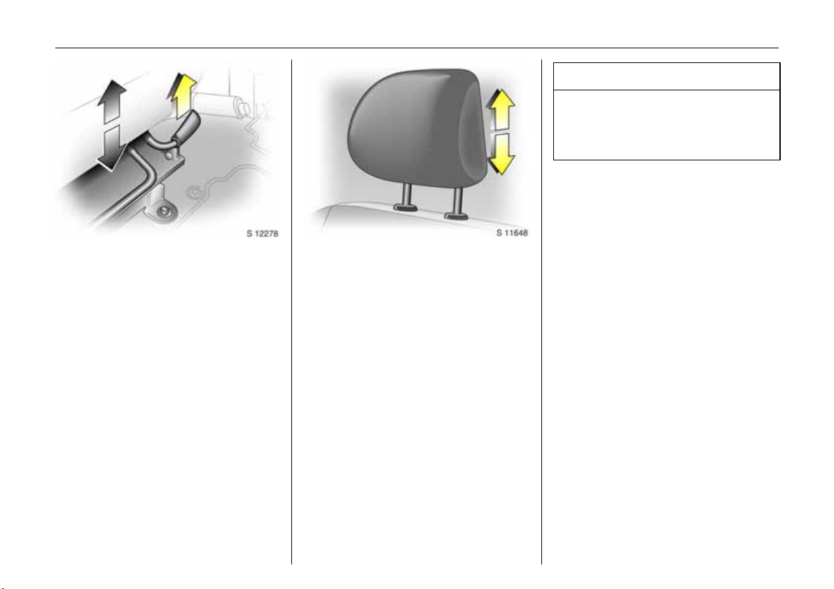
Adjusting seat height
3:
Pull lever at side
Lift lever and remove weight from seat to
raise it or press down on seat with body
weight to lower it.
Never adjust the driver’s seat whilst driving.
It could move in an uncontrolled manner
when the lever has been pulled.
6 Seat position – see page 47.
Adjusting head restraint height:
hold firmly and adjust height,
then release
6 Head restraint position – see page 47,
further information, removal – see page 48.
Page 9
In brief 5
6 Seat belts – see pages 57 to 59,
airbag systems 3 – see page 61,
seat position – see page 47.
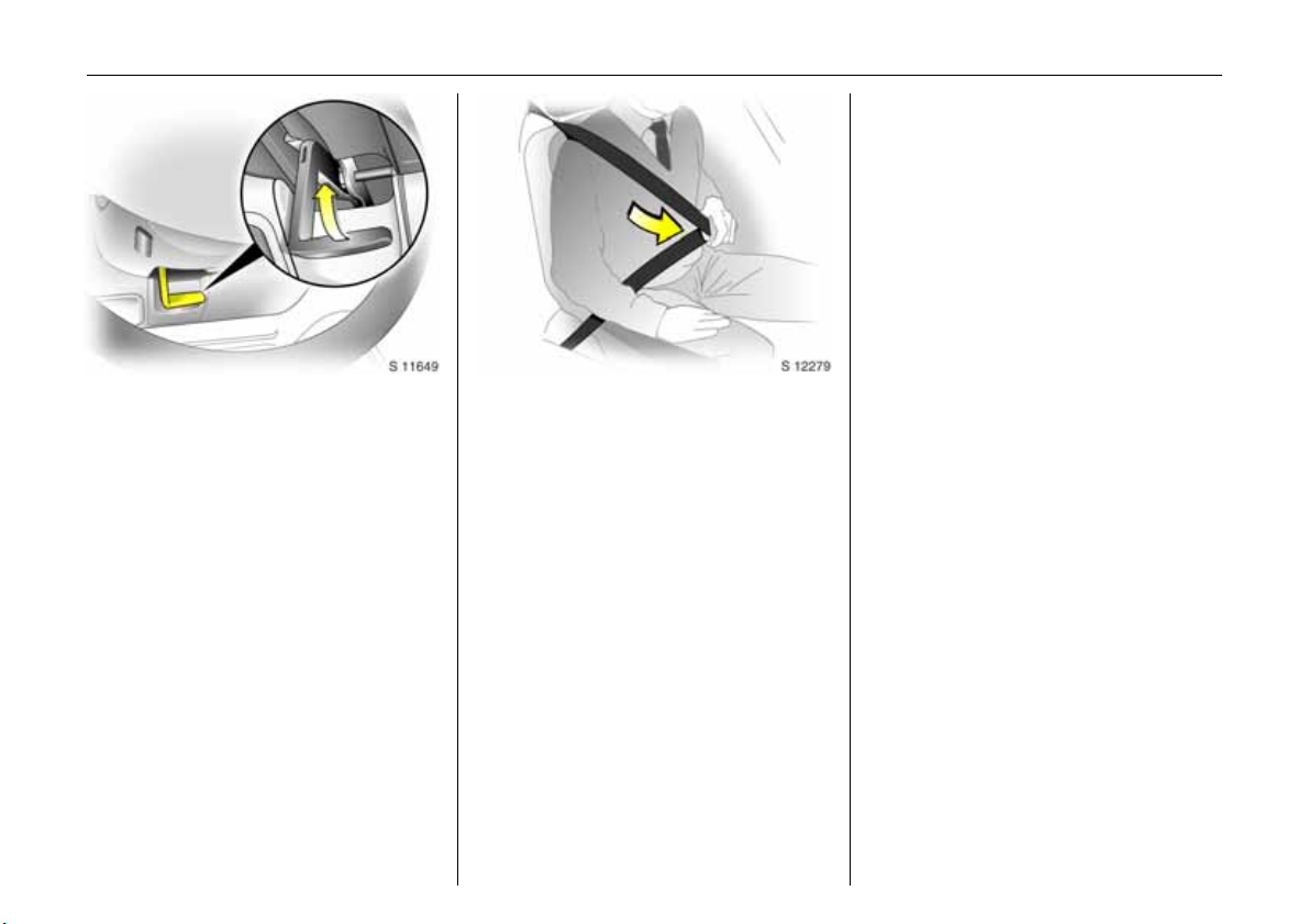
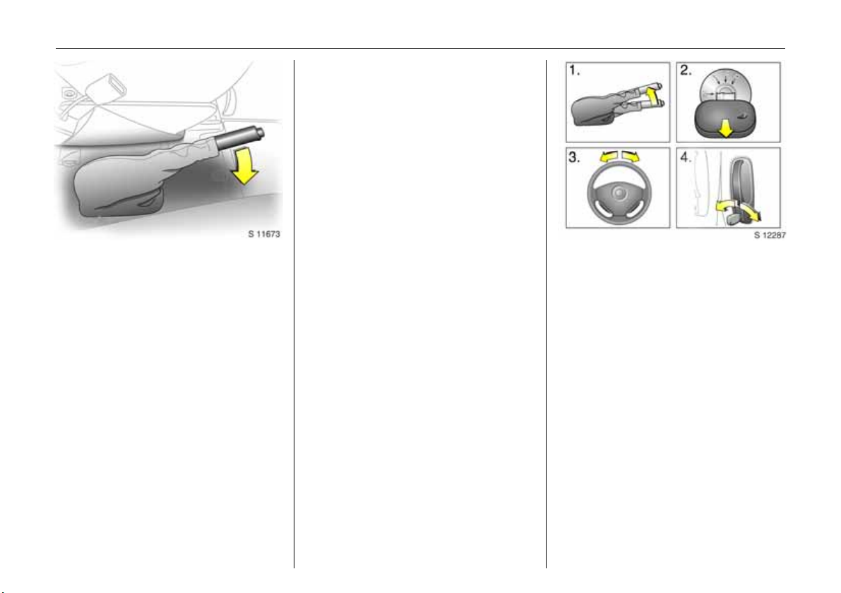
Steering wheel adjustment:
Adjust position
Adjust the steering wheel only when the
vehicle is stationary.
Move the unlocking lever upwards, adjust
the wheel to the desired position, then
release the lever.
Push the lever firmly downwards to ensure
that the wheel is locked in position.
6 Airbag systems - see page 61.
Fitting seat belt:
Draw seat belt smoothly from
inertia reel, guide over shoulder
and engage in buckle
The belt must not be twisted at any point.
The lap belt must lie snugly against the
body. The backrest must not be tilted back
too far (recommended tilting angle
approx. 25°).
To release belt, press red button on belt
buckle.
Page 10
In brief6
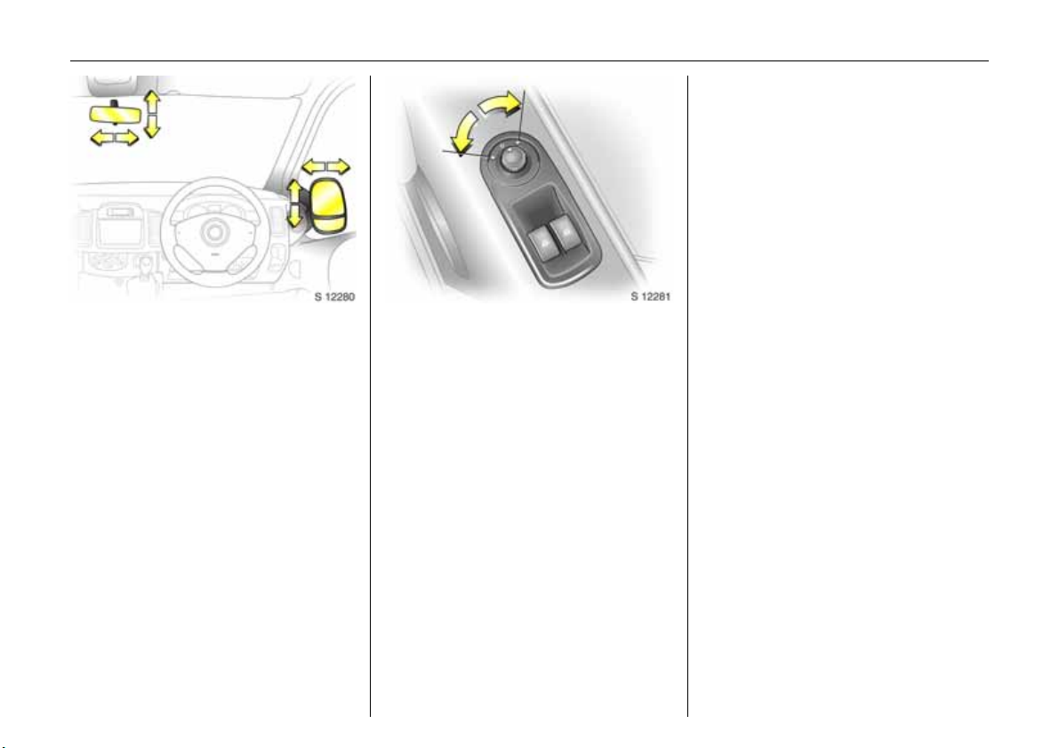
Turn switch to right: switch operates righthand mirror.
Switch in central position: mirror
adjustment is off.
The lower aspherical mirrors are not
adjustable.
Adjust interior
3 and exterior
mirrors:
Swivel to appropriate position
Move lever on underside of interior mirror
housing to reduce dazzle at night.
6 Further information - see page 74.
Electrically adjustable exterior
mirrors 3:
Switch in door panel
Operational with the ignition on or off.
Turn switch to left: switch operates left-
hand mirror.
Page 11
In brief 7
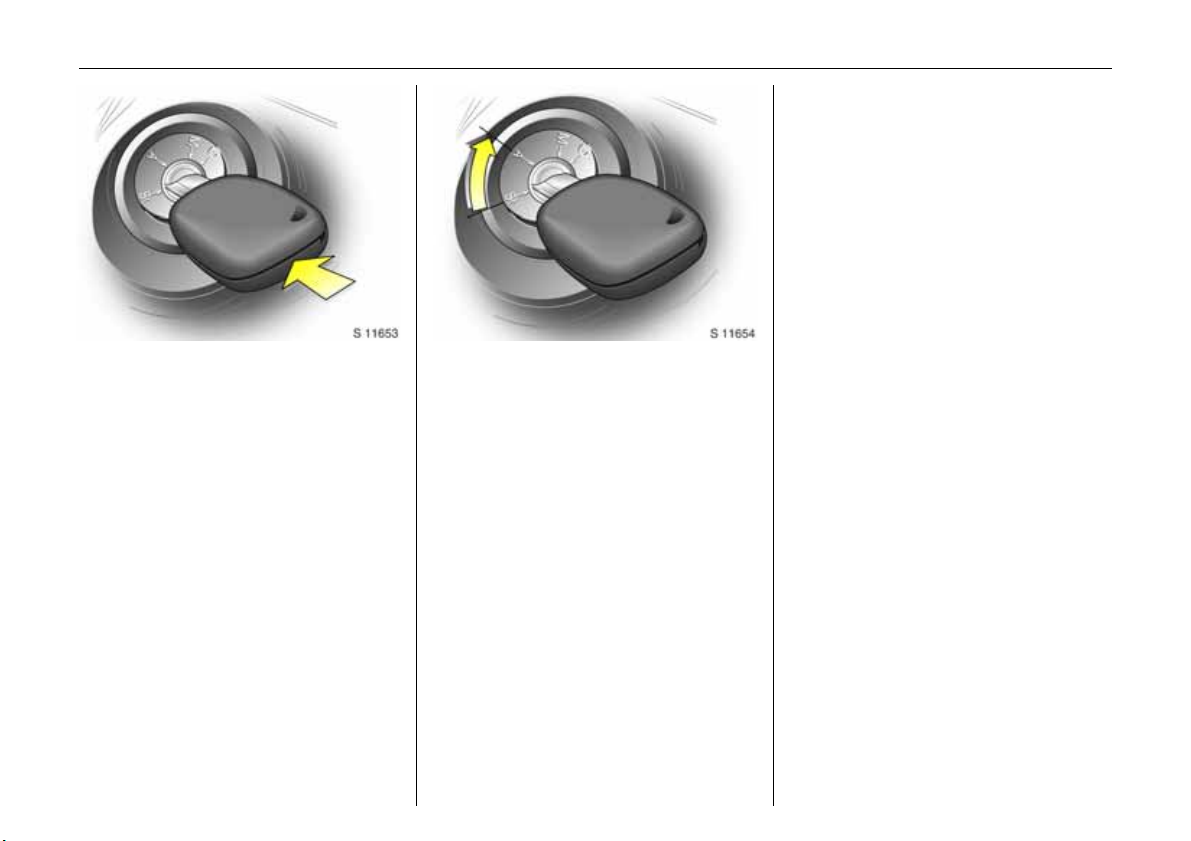
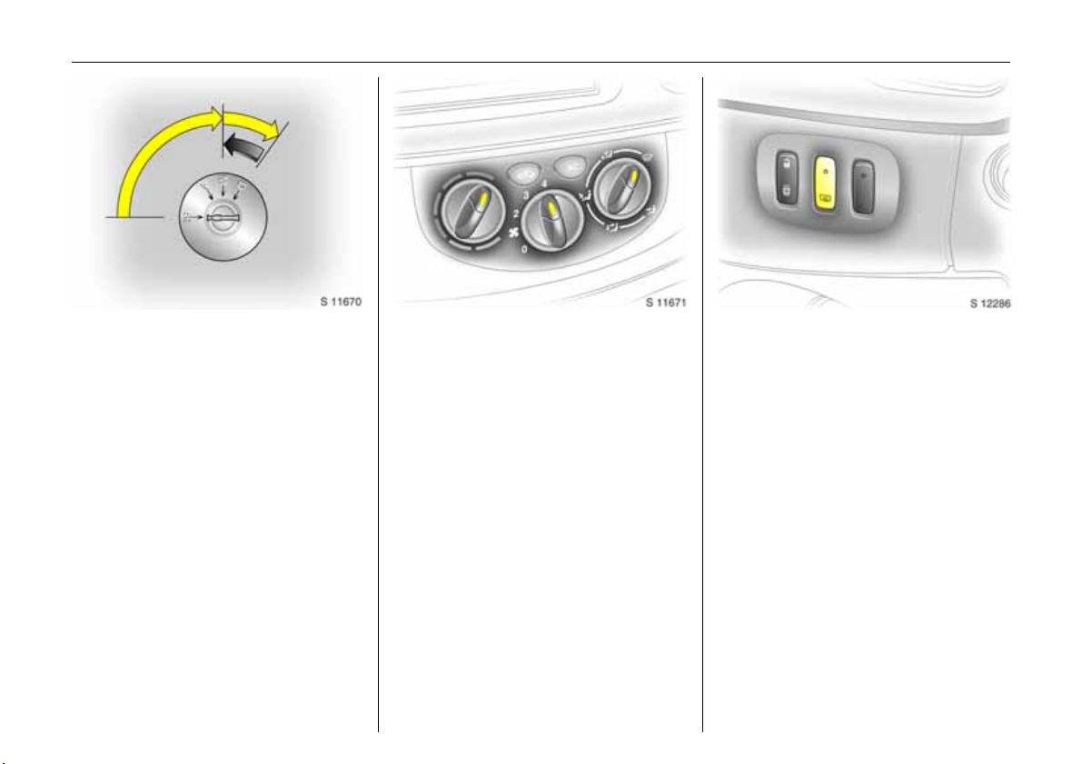
Starter switch:
Diesel engine
St = Ignition off
A = Steering unlocked, ignition off
M = Ignition on: preheat (page 17)
D = Start - (transmission in neutral)
Petrol engine
St = Ignition off
A = Steering unlocked, ignition off
M = Ignition on
D = Start - (transmission in neutral)
6 Electronic immobilizer - see page 38.
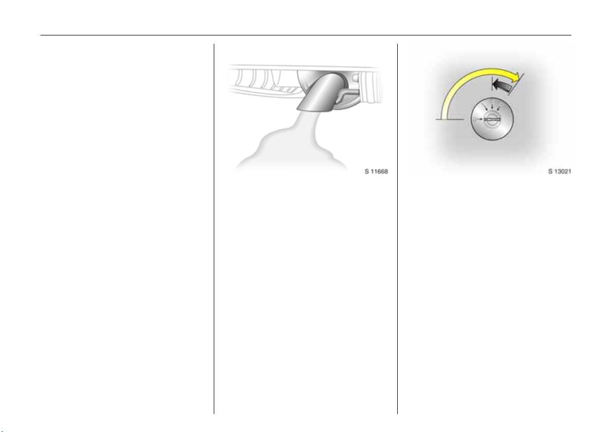
Releasing the steering column
lock:
To release the lock,
move steering wheel slightly
and turn key to position ‘A’
6 Remove key and lock steering wheel - see
page 18.
Page 12
8 In brief
Page 13

In brief 9
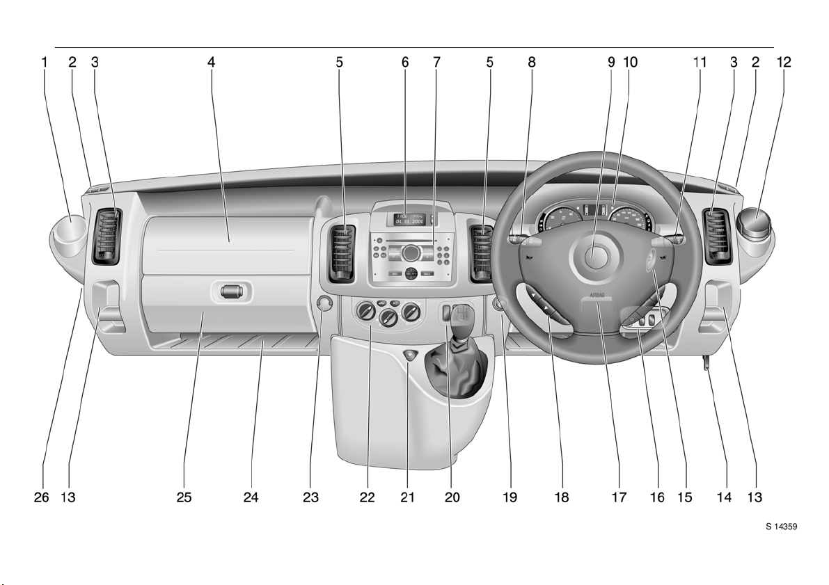
1 Drink holder....................................... 55
Page
2 Door window defroster vent.............83
3 Side ventilation jets........................... 83
4 Passenger airbag 3.......................... 61
5 Centre ventilation jets....................... 82
6 Triple information display 3 ............ 29
Colour information display 3........... 31
7 Infotainment system 3..................... 35
Electronic tachograph 3 ..................36
8 Lever for
Parking lights, headlights flash,
fog lights, dipped and main beam 12
turn signal lights................................ 13
9 Driver’s airbag .................................. 61
Horn ................................................... 13
10 Instruments........................................ 20
11 Lever for windscreen wiper
and wash system .............................14
Trip computer 3................................ 26
12 Ashtray ............................................. 55
13 Coin tray
14 Bonnet release lever ......................... 46
15 Starter switch ...................................... 7
16 Switches for
headlight range adjustment............ 76
ESP
(Electronic Stability Program) 3 .... 106
Parking distance sensor 3 .............107
17 Steering wheel adjustment lever ....... 5
18 Infotainment controls 3 .................. 35
19 Cigarette lighter................................ 54
20 Switches for
central locking 3............................... 41
heated rear window 3...................... 87
Tecshift 3 winter and laden
programme ....................................... 91
21 Hazard warning switch .................... 13
22 Heating and ventilation controls .... 81
Rear air conditioning 3 .................... 86
23 Utility hook
24 Storage tray
25 Glove compartment
26
Fuse box .......................................... 137
Page
Page 14

In brief10
Control indicators
Ü Not used
9 Headlight dipped beam:
see pages 12, 75.
P Headlight main beam:
see pages 12, 75.
r Fog tail light:
see pages 12, 77.
Front fog lights 3:
>
see pages 12, 77.
u Anti-lock brake system 3:
see page 115.
8 Diesel particle filter 3:
see page 104.
C Stop engine:
see page 21.
o Engine immobiliser:
see pages 21, 38.
A Service 3:
see page 21.
O Turn signal lights:
see pages 13, 76.
Y Fuel level:
see pages 21, 100, 163.
ESP (Electronic Stability
v
Program) 3:
see page 106.
Engine electronics/Preheating
D
system 3:
see page 17.
E Engine stop:
see page 21.
p Alternator:
see page 22.
I Oil pressure:
see page 22.
R Brake system:
see pages 22, 151.
Airbag systems:
v
see page 61.
Front passenger
H
airbag deactivation 3:
see page 65.
Driver’s seat belt:
X
see page 57.
Door open 3:
U
see pages 23.
U Not used
Engine electronics,
Z
Exhaust emissions:
see page 23.
Not used
B
Engine oil life monitor 3:
F
see page 29.
Tecshift 3
Winter programme:
V
see page 91.
Laden programme:
kg
see page 92.
Transmission electronics:
W
see page 94.
Brake pedal application:
T
see page 89.
Automatic mode:
A
see page 90.
Page 15

Lighting Heating and ventilation Windscreen wiper
7 Light switch:
see pages 12, 75.
0 Parking lights:
see pages 12, 75.
9 Dipped beam:
see pages 12, 75.
P Main beam:
see pages 12, 75.
Front fog lights 3:
>
see pages 12, 77.
r Fog tail light:
see pages 12, 77.
O Turn signal lights:
see pages 13, 21.
¨ Hazard warning flashers:
see page 13, 76.
? Headlight range adjustment:
see page 76.
x Fan switch:
see page 82.
Air distribution:
see page 81,
M to head area
L to head area and to foot area
K to foot area
J to head area and to demister
V to demister
Ü Heated rear windows and
mirrors 3:
see pages 17, 87.
A.C
Air conditioning system 3:
see page 85.
4
Air circulation:
see page 85.
Lever positions:
see page 14,
K Timed interval wipe or automatic
wiping with rain sensor 3
1
Slow
2
Fast
n Windscreen wash
e Tailgate window wiper 3
f Tailgate window wash 3
Miscellaneous
j Horn:
see page 13.
/
Bonnet:
see page 46.
) Cigarette lighter:
see page 54.
e/U Central locking 3:
see page 41.
: Glove compartment cooler 3:
see page 86.
E Parking distance sensor 3:
see page 107.
In brief 11
Page 16
In brief12
Light switch:
7 =Off
0 =Parking lights
9 P = Dipped or main beam
6 Headlight warning device - see page 18,
further information - see page 75,
Automatic dipped beam activation 3
- see page 76,
headlight range adjustment - see page 76,
headlights when driving abroad
- see page 78,
daytime running lights 3 - see page 75.
Fog lights:
7 =Off
> = On (front fog lights 3 only)
>r = On (front fog lights 3 and
fog tail light)
The fog lights will only illuminate when the
ignition and headlights are switched on.
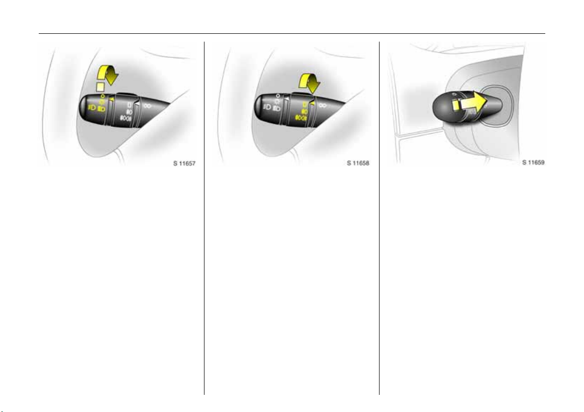
Dipped and main beam:
Headlight flash:
Pull lever towards steering wheel
To change the headlight beam, pull the
lever towards the steering wheel, then
release when a click is felt.
Pulling the lever towards the steering wheel
to the first stop operates the headlight
flash.
Page 17
In brief 13
Turn signal lights:
Lever in rest position
Upwards = Right turn
Downwards = Left turn
When the steering wheel is turned back, the
lever automatically returns to its original
position. This will not happen when making
a minor steering manoeuvre such as lane
changing.
When lane changing, move lever part way
to first stop. When released, lever will
spring back.
For operation of the turn signal lights when
towing - see pages 20 and 122.
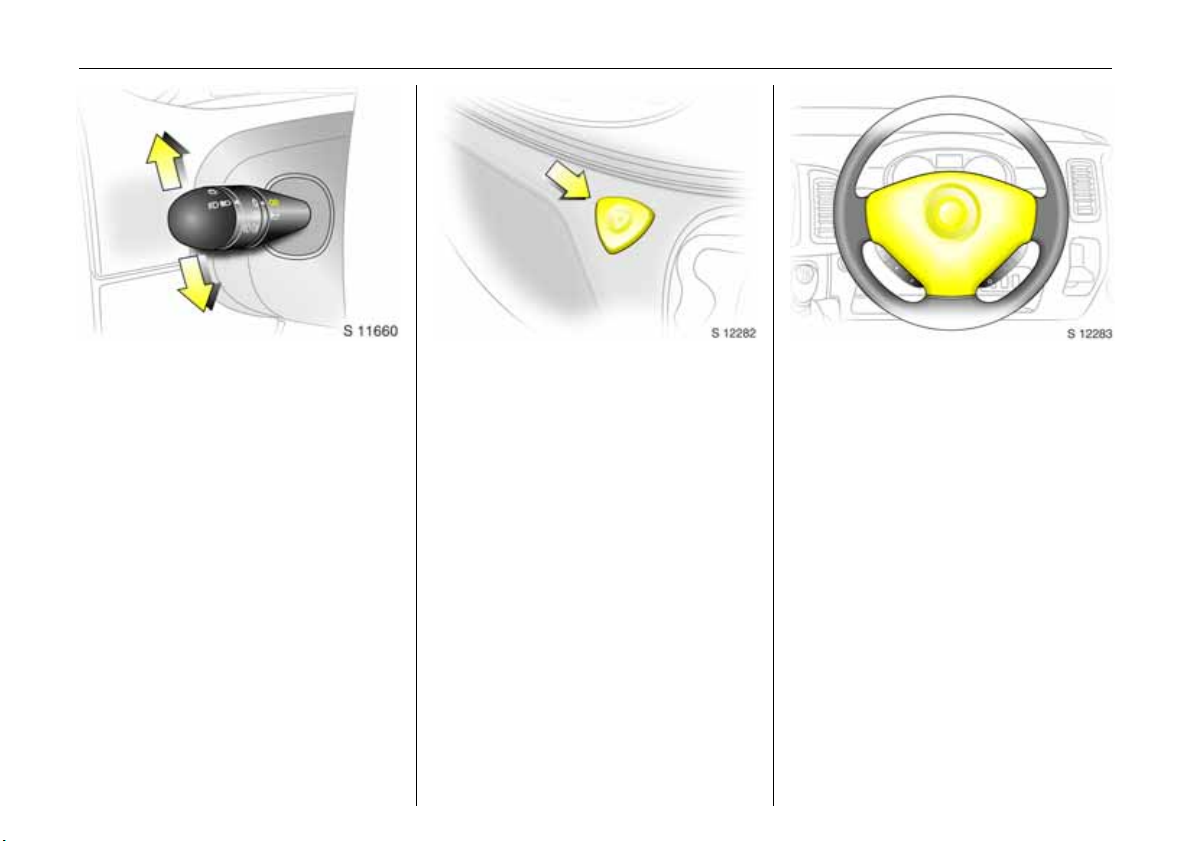
Hazard warning flashers:
On = Press button ¨
Off = Press ¨ again
When the hazard warning system is
actuated, the button's control indicators
flash in unison with the turn signal lights.
Horn:
Press any part of the steering wheel centre
to activate the horn.
Page 18
In brief14
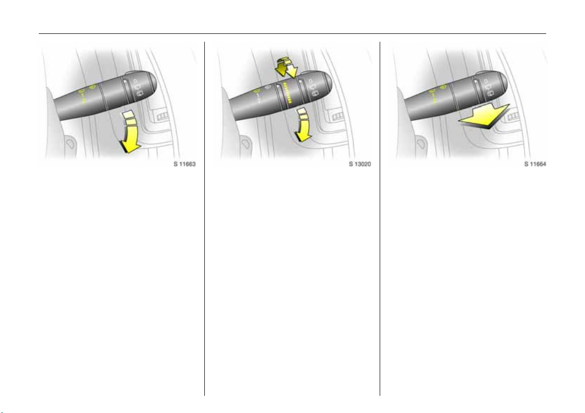
Windscreen wiper:
Move lever downwards
K = Timed interval wipe
1 =Slow
2 =Fast
Return the lever to its original position to
turn off.
Automatic wiping with
rain sensor 3:
Move lever downwards
K = Automatic wiping with
rain sensor
1 =Slow
2 =Fast
The rain sensor detects the amount of
water on the windscreen and automatically
regulates the windscreen wiper frequency.
The sensitivity of the system can be
adjusted by rotating the variable wipe:
Less sensitive = rotate down
More sensitve = rotate up
Upon starting the engine, automatic
wiping will need to be reselected.
6 Further information - see pages 153, 158.
Windscreen wash system:
Pull lever towards steering wheel
Short pull
The wiper operates for one cycle.
Long pull
Wash fluid is sprayed onto the windscreen,
at the same time the wiper is operated for
four cycles.
Check regularly that the windscreen wash
system is operating efficiently.
On vehicles with rain sensor 3, keep the
sensor area clean.
6 Further information - see page 153.
Page 19
In brief 15
Back door and tailgate window
wash wipe system
3:
Rotate switch
0=Off
e =Wiper
f =Wash
Wash fluid is sprayed onto the window
when the lever is moved to the second
position. The switch is spring loaded and
will return to the ’wiper’ position when
released.
Check regularly that the window wash
system is operating efficiently.
6 Further information - see page 153.
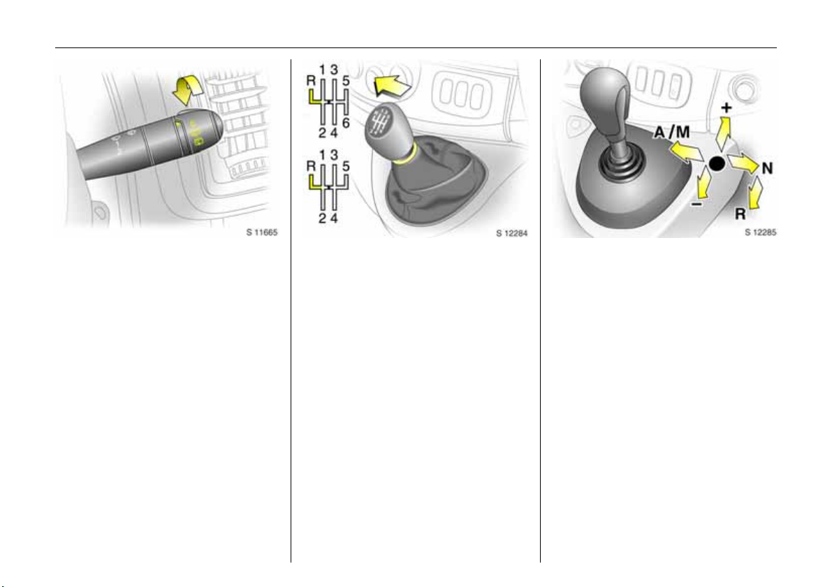
Manual transmission:
o =Neutral
1 to 5/6= 1st to 5th or 6th 3 gear
R = Reverse gear
When shifting up from 4th to 5th gear,
pressure must be exerted towards the right
at the beginning of the shift operation.
When shifting from 5th to 4th gear, do not
exert any force towards the left.
Reverse gear: with vehicle stationary,
declutch, pull up collar and move shift lever
to the left against resistance.
If the gear does not engage: with lever in
neutral, release clutch pedal and depress
again, then repeat gear selection.
Tecshift 3:
N=Neutral
o = Centre position
- = Shift to lower gear
+ = Shift to higher gear
A/M = Switch between
automatic or manual
mode
R = Reverse
The selector lever must be moved in the
appropriate direction as far as it will go.
Upon release, it automatically returns to
the centre position. Pay heed to the
gear / mode indicator in the transmission
display.
6 Further information - see page
89.
Page 20
In brief16
Before driving check:
z Tyre pressures and condition.
z Engine oil level and fluid levels in engine
compartment (see pages 145 to 148).
z All windows, mirrors, exterior lighting
and number plates free from dirt, snow
and ice and operational.
z Objects are securely located and will not
be thrown forward in the event of
sudden braking.
z Seats, seat belts and mirrors correctly
adjusted.
z Brake operation.
Exhaust gases are poisonous
Exhaust gases contain carbon monoxide,
which is extremely poisonous but has no
odour or colour.
Therefore, never inhale exhaust gases, and
never run the engine in an enclosed space.
You should also avoid driving with the
doors open, as exhaust gases could enter
the passenger compartment.
6 Exhaust gas - see page 105.
Starting, petrol engine:
Transmission in neutral
Depress clutch
Do not accelerate
Turn key to D
The increased engine speed automatically
returns to normal idling speed as the
engine temperature rises.
6 Electronic immobilizer - see page 38,
further information - see pages 96, 97, 99.
Page 21
In brief 17
Starting, diesel engine:
Transmission in neutral
Depress clutch
Do not accelerate
Turn key to M
When preheating control
indicator goes out
1)
,
turn key to D
6 Electronic immobilizer - see page 38,
further information - see pages 96, 97, 99.
1)
Preheating system switches on only if outside
temperature is low.
Drying misted-up or iced-up
windows:
Set the temperature switch to red
and fan to position 4,
set air distribution to V
Close centre ventilation jets; open side
ventilation jets and direct them towards
the door windows.
6 Heating, ventilation - see page 81,
air conditioning system - see page 85.
Heated rear windows 3,
heated exterior mirrors 3
Ü =On
Press
Press Ü again = Off
6 Further information - see page 87.
Page 22
In brief18
Releasing the hand brake:
Raise lever slightly,
press lock button,
lower lever fully
Drive carefully, economically and with the
environment in mind. While driving, do not
do anything that could distract you.
Warning buzzers
While driving:
z Operating the indicators.
z Illumination of low fuel control indicator.
z Tecshift 3, high clutch temperature.
z Seat belt not fastened 3.
When the vehicle is parked and driver’s
door is opened:
z Headlights switched on.
z Tecshift 3: neutral not selected, foot
brake not depressed or handbrake not
applied.
6 Driving hints - see page 95,
Save fuel, protect the environment - see
page 97.
Parking the vehicle:
Apply hand brake firmly
Close windows
Switch off engine
Remove key
Engage steering wheel lock
Lock doors
6 Further information - see pages 38, 96,
remote control - see page 39,
central locking system - see page 41,
Vauxhall alarm system - see page 43.
Page 23
In brief 19
Advice when parking:
z Always apply hand brake firmly. Engage
first gear or reverse gear. On slopes
apply the hand brake as far as it will go.
z Turn steering wheel until lock is felt to
engage (anti-theft protection).
z Switch off exterior lights, otherwise the
headlight warning device will sound
when the driver’s door is opened.
z Cooling fans may run on after the engine
has been switched off.
z Do not park vehicle on easily ignitable
surfaces as the hot exhaust system could
cause the surface to ignite.
Service work, maintenance
We recommend that you entrust all work to
your Vauxhall Authorised Repairer, who
can provide you with reliable service and
correctly perform all work according to
factory instructions.
Vauxhall Service - see page 142.
Genuine Vauxhall Parts and
Accessories
We recommend “Genuine Vauxhall Parts
and Accessories” and conversion parts
released expressly for your vehicle type.
These parts have undergone special tests
to establish their reliability, safety and
specific suitability for your vehicle. Despite
continuous market monitoring, we cannot
assess or guarantee these attributes for
other products, even if they have been
granted approval by the relevant
authorities or in some other form.
"Genuine Vauxhall Parts and Accessories"
and conversion parts approved by
Vauxhall can be obtained from your
Vauxhall Authorised Repairer, who can
give advice about permitted technical
changes and correct installation.
9 Warning
Carry out regularly the checks
recommended in this Owner's Manual.
Ensure that your vehicle is serviced at the
service intervals specified in the Service
Booklet. We recommend that you entrust
this work to your Vauxhall Authorised
Repairer.
Have faults remedied without delay!
Consult a workshop. We recommend your
Vauxhall Authorised Repairer. If
necessary, interrupt your journey.
6 Maintenance - see pages 144 to 155.
That was a brief overview of the
most important information for
your first drive in your Vivaro.
Your vehicle has still more
instruments and controls,
possibly also optional
equipment.
The remaining chapters of the
Owner’s Manual contain
important information on
operation, safety and
maintenance as well as a
complete index.
Page 24
20 Instruments
Instruments
Control indicators ............................... 20
Tachometer......................................... 23
Speedometer....................................... 23
Fuel gauge .......................................... 24
Coolant temperature gauge.............. 24
Multifunction display.......................... 25
Electronic odometer/clock 3.............. 26
Trip computer 3 ................................. 26
Engine oil life monitor 3..................... 29
Triple information display 3 .............. 29
Colour information display 3,
selecting functions ........................... 31
Radio 3................................................ 35
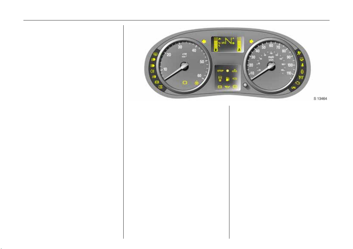
Control indicators
The control indicators described here are
not present in all vehicles. The description
applies to all instrument versions.
Ü
Not used
9
Headlight dipped beam
Lights up when dipped beam is on.
P
Headlight main beam
Lights up when main beam is on and when
headlight flash is operated.
r
Fog tail light
Lights up when the fog tail light is switched
on.
>
Front fog lights 3
Lights up when front fog lights are
switched on.
u
Anti-lock brake system
see page 115.
8
Diesel particle filter 3
Lights up when regeneration of diesel
particle filter is required - see page 104.
F
Not used
Page 25

Instruments 21
v
ESP (Electronic Stability Program) 3
see page 106.
F
Engine oil life monitor 3
See page 29.
kg
Tecshift Laden programme 3
Control indicator illuminates in
transmission display when Laden
programme is enabled - see page 92.
T
Tecshift foot brake application 3
see page 89.
W
Tecshift electronics 3
Lights up briefly when ignition is switched
on. Illuminates in transmission display
when fault has occurred - see page 94.
A
Tecshift automatic mode 3
Control indicator illuminates in
transmission display when automatic
mode is selected - see page 90.
V
Tecshift Winter programme 3
Control indicator illuminates in
transmission display when Winter
programme is enabled - see page 91.
O
Turn signal lights
Flashes when turn signal lights are on.
Flashes rapidly: a turn signal bulb has
failed.
An audible warning can be heard when the
turn signal lights are on. When towing a
caravan or trailer, the pitch of the audible
warning changes.
C
Stop engine
C lights up in conjunction with p, I,
If
E or R, stop engine immediately and
consult a workshop. We recommend your
Vauxhall Authorised Repairer.
o
Engine immobilizer
If the indicator flashes when the ignition is
on, there is a fault in the immobilizer
system; the engine cannot be started - see
page 38.
A
Service / engine electronics 3
If A lights up in conjunction with u or v,
interrupt your journey. Consult a workshop.
We recommend your Vauxhall Authorised
Repairer.
D
Preheating/Fuel filter/Engine electronics
Lights up briefly during engine preheating.
If illuminated constantly it indicates:
z The presence of water in the diesel fuel
filter 3. Drain fuel filter of residual water,
see page 149.
z An electronic system failure, consult a
workshop. We recommend your
Vauxhall Authorised Repairer.
Y
Fuel level
If it lights up: fuel level low, fill up.
Never let the tank become empty!
With diesel engines it is not possible to start
the engine after the tank has been run
empty. The fuel system must be bled first.
Page 26

Instruments22
E
Engine stop
Will light up in conjunction with
if coolant temperature is too high. Stop
vehicle - consult a workshop. We
recommend your Vauxhall Authorised
Repairer.
p
Alternator
Lights up when ignition is switched on.
Goes out after engine is started.
If illuminated during driving:
Stop vehicle and switch off engine. The
battery is not being charged and the
engine cooling may be interrupted. The
brake servo unit may cease to be effective.
Interrupt your journey, consult a workshop.
We recommend your Vauxhall Authorised
Repairer.
C engine
I
Oil pressure
Lights up when ignition is switched on.
Goes out after a short period of time. Can
light up intermittently when idling with hot
engine; must go out when engine speed is
increased.
If illuminated during driving:
Engine lubrication may be interrupted,
resulting in damage to the engine and/or
locking of the driving wheels:
z Depress clutch.
z Move gear shift lever to neutral.
z Switch off ignition (to position A).
Considerably greater force will be
required for braking and steering.
9 Warning
Do not remove key until vehicle has come
to a standstill, otherwise the steering
column lock could engage unexpectedly.
Consult a workshop. We recommend your
Vauxhall Authorised Repairer.
R
Brake system
Lights up when ignition is switched on if
hand brake is applied and/or fluid level for
brake hydraulics is too low.
9 Warning
If it lights up when the hand brake is not
applied: stop vehicle; interrupt your
journey immediately. Consult a
workshop. We recommend your Vauxhall
Authorised Repairer.
6 Further information - see page 113.
v
Airbag 3
see page 61.
H
Front passenger airbag deactivation 3
Lights up when the ignition is switched on
and remains illuminated when the front
passenger airbag has been deactivated.
If H illuminated in conjunction with v
consult a workshop. We recommend your
Vauxhall Authorised Repairer.
6 Further information - see page 65.
or A
Page 27
X
Driver’s seat belt
Lights up when ignition is switched on and
if driver’s seat belt is not engaged.
Seat belts, see page 57.
U
Door open 3
Operational only when ignition is switched
on. Lights up when driver’s, passenger’s or
side loading doors are open.
U
Not used.
Z
Exhaust emissions 3
Control indicator lights up when ignition is
switched on. Goes out shortly after engine
starts.
If it lights up when the engine is running:
Fault in emission control system. The
permitted emission limits may be
exceeded. Consult a workshop. We
recommend your Vauxhall Authorised
Repairer.
If it flashes when the engine is running:
For fault that can lead to destruction of the
catalytic converter, see page 102. Consult
a workshop immediately. We recommend
that you consult your Vauxhall Authorised
Repairer.
B
Not used
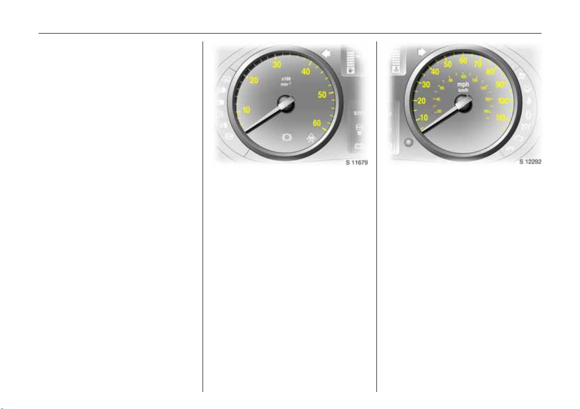
Tachometer
Making use of the tachometer helps to
save fuel; it indicates the engine speed in
revolutions per minute.
Warning zone on right: maximum
permissible engine speed exceeded,
danger to engine.
If possible, drive in each gear in the low
engine speed range (between approx.
2000 and 3000 rpm) and maintain an even
vehicle speed.
Instruments 23
Speedometer
Indicates the vehicle speed.
Certain vehicle variants feature a speed
regulator 3
maximum speed. As a visible indication of
this, a warning label is located on the
instrument panel.
1)
Depending on driving environment (e.g. when
descending steep inclines) the vehicle speed
can exceed set limits. In such instances it
remains the driver’s responsibility to adhere to
the specific speed limits.
1)
which restricts the vehicle
Page 28
Instruments24
For physical reasons, the coolant
temperature gauge shows the coolant
temperature only if the coolant level is
adequate.
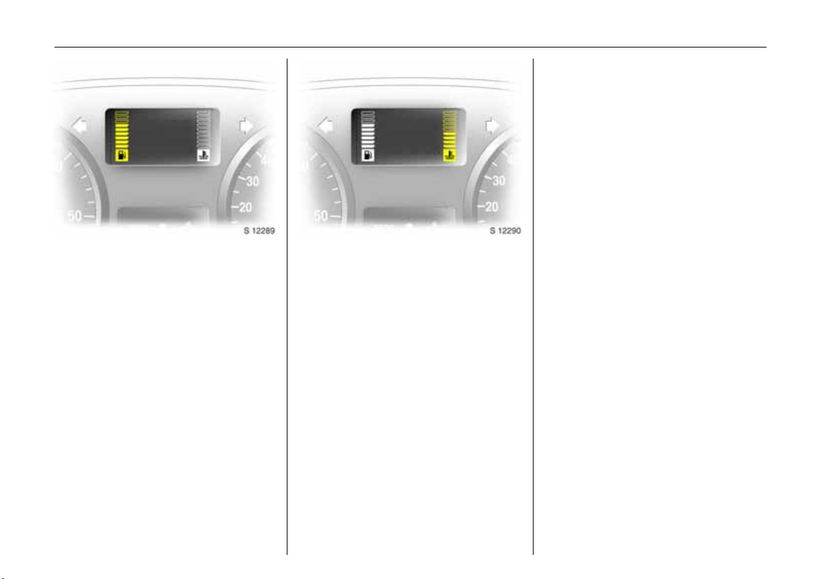
Fuel gauge
Display of fuel level:
Illumination of bars displays fuel level.
When gauge indicates fuel supply low, fuel
warning
See page 99.
Never let tank become empty!
Y illuminates = fill up.
Coolant temperature gauge
Display of coolant temperature:
Bars illuminated
in lower area
Bars illuminated
up to central
area
Bars illuminated
into uppermost
zone
or indicator
illuminates 3
= Engine operating
temperature not yet
reached
= Normal operating
temperature
= Temperature too
high. Stop vehicle,
E
switch off engine.
Danger to engine.
Check coolant level
immediately. See
page 150.
Page 29
Instruments 25
Multifunction display
Transmission display 3
Display of the selected gear and mode with
Tecshift 3.
N Neutral or idling position.
R Reverse gear.
A Automatic mode.
kg Laden programme.
V Winter programme.
T Foot brake application.
W Transmission electronics.
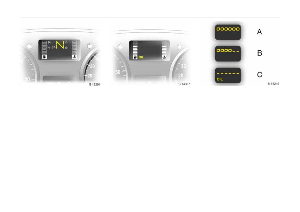
Oil level display 3
The oil level display is correct only if the
vehicle is parked on level ground with a
cold engine. The oil level display will only
be reset if the ignition has been switched
off for more than two minutes.
If "oil" appears in the display the oil level
may need topping up. To gain a more
accurate indication of the oil level, press
and hold the reset button - see page 28.
The squares that appear on the display
indicate the level. As the oil level
diminishes, the squares in the display
disappear and are replaced with dashes.
A: Maximum level
B: Intermediate level
C: Minimum level = check and top up
engine oil
1)
A illuminates if oil level is too low.
To return to the normal display, press the
reset button again.
Checking and topping up fluids - see page
145.
1)
Page 30
Instruments26
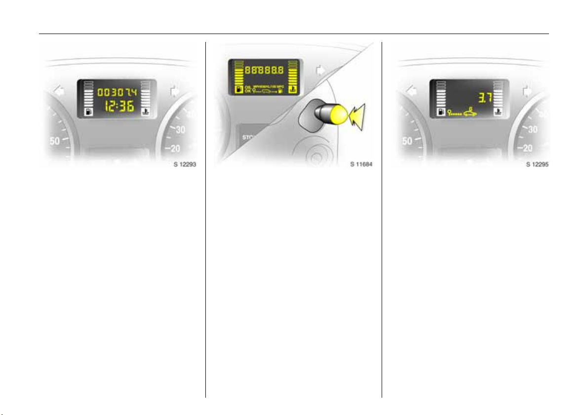
Electronic odometer/clock 3
Normal mode:
The odometer and clock are visible.
Reset:
The reset button is located alongside the
speedometer. Press button once to display
the trip odometer.
Press the button and hold, the display will
flash and after 1 second will reset to zero.
Press the button again to return the
odometer to normal mode.
Clock adjust mode:
With the display in normal mode press and
hold the button, and the minutes reading
will begin to increase.
After the button is released the clock will
continue to flash for a further 5 seconds to
enable further adjustments to be made.
Trip computer 3
In addition to the electronic odometer
functions, the trip computer can also
display additional monitored vehicle data;
z Fuel used,
z Average consumption,
z Instantaneous consumption,
z Range,
z Distance travelled,
z Average speed.
Pressing the selection switch located on the
end of the windscreen wash control lever
will cycle through these displays.
Fuel used
Displays the amount of fuel consumed
since the last reset. The measurement can
be restarted at any time – see page 28.
Page 31

Instruments 27
Average consumption
Is displayed, taking into consideration the
distance travelled and the fuel used since
the last reset. The measurement can be
restarted at any time - see page 28.
Instantaneous consumption
The value is displayed after reaching a
speed of 15 mph (25 km/h).
Range
The range is calculated from the current
contents of the fuel tank and the average
consumption since the last reset
- see page 28.
Page 32

Instruments28
Distance travelled
Displays the distance driven since the last
reset. The measurement can be restarted
at any time.
Average speed
The average speed is displayed, since the
last reset. The measurement can be
restarted at any time.
Stoppages in the journey with the ignition
off are not included in the calculations.
Reset current trip computer information
The following trip computer information
can be reset:
z Fuel used,
z Average consumption,
z Range,
z Distance travelled,
z Average speed.
To reset the trip computer, select one of its
functions then press and hold the reset
button, the display will flash and after 1
second will reset.
Interruption of power supply
If the power supply has been interrupted or
if the battery voltage has dropped too low,
the values stored in the trip computer will
be lost.
Page 33

Instruments 29
Engine oil life monitor 3
Each time the ignition is switched on, the
remaining distance before the next engine
oil and filter change is due may be shown
in the display for approx. 5 seconds.
Within 1 800 miles (3 000 km) of the next
engine oil change being due, the remaining
distance and F will be displayed for
approx. 30 seconds as a reminder. Make
an appointment with a workshop for
service work as soon as possible. We
recommend your Vauxhall Authorised
Repairer.
6 Further information - see page 105.
Triple information display 3
Display for time, outside temperature,
radio/date.
When the ignition is off, the time, date and
outside temperature can be made to
appear for approx. 15 seconds by briefly
pressing one of the two buttons beside the
display.
Setting date and time
Switch off radio. Press Ö and ; beside
display as follows:
Press Ö for approx. 2 seconds:
Day flashes
;:Set day
Ö:Month flashes
;:Set month
Ö:Year flashes
;:Set year
Ö:Hours flash
;: Set hours
Ö:Minutes flash
;:Set minutes
Ö: Clock starts at 0 seconds.
Page 34

Instruments30
If only the time is to be set, repeatedly
press Ö with display in setting mode until
hours/minutes flash.
Automatic date and time setting 3
Possible in the case of radio reception from
RDS stations
signal.
Automatic setting is carried out once the
radio has been switched on and a RDS time
signal has been received. The setting is
indicated by } in the display. If no time
signal is received, or the time signal is
inaccurate, the date and time must be set
manually.
Deactivating and activating the automatic
setting function (e.g. if an inaccurate time
signal is received from the broadcasting
station):
Press Ö for approx. 2 seconds; the time
Press Ö twice (until year flashes).
Press Ö for approx. 3 seconds until } in
Press ; Display indicates:
Press Ö three times.
1)
which broadcast a time
display is now in setting mode.
display flashes and the display
“RDS TIME” appears (years
flash while button is depressed).
RDS TIME 0 = Deactivated
RDS TIME 1 = Activated
Fault display
Display --.-°C or an F in the display
indicates a fault. Have the cause
eliminated, consult a workshop. We
recommend your Vauxhall Authorised
Repairer.
Interruption of power supply
If the power supply has been interrupted or
if the battery voltage has dropped too low,
the date and time must be reset.
When the battery has been reconnected or
charged, set the date and time as
described under “Setting date and time”.
In the case of radios with RDS 3, the time is
set automatically when the radio is
receiving an RDS station which broadcasts
a time signal (see page 30).
Outside temperature
A fall in temperature is indicated
immediately and a rise in temperature
after a time delay.
9 Warning
Caution: The road surface may already
be icy even though the display indicates
a few degrees above 0 °C.
If the external temperature falls to 3 °C, to
warn of ice on the road the symbol :
appears on the Triple Info display.
When the temperature climbs, the symbol
: goes out above 5 °C.
1)
RDS = Radio Data System.
Page 35

Slippery road
-2,5°C
OK
Instruments 31
In vehicles with colour information display
3, a warning message appears in the
display as a warning for icy road surfaces.
There is no message below -5 °C
9 Warning
Caution: The road surface may already
be icy even though the display indicates
a few degrees above 0 °C.
Colour information display 3,
selecting functions
Functions and their menus are depicted in
the information display.
These functions are marked or executed in
the menu display via the cross switch, the
multifunction knob 3 on the Infotainment
System or buttons 3 on the steering wheel.
To select with four-way button:
Select menu items via menus and
with the buttons/four-way button of
the Infotainment system.
Selection with the multifunction knob 3:
Turn Mark menu items
or commands, select
functions.
Press Select marked item,
confirm command.
To exit a menu, turn the multifunction
button left or right to Return or Main
and select.
Page 36

Instruments32
7 Settings 19,5° 19:36
FM AS [TP] REG CDin MP3
90.6
MHz
19,5° 19:36
Time, Date 19:36
Language
Units 10 . 07 . 2004
Contrast
Day / Night
6 Ign. logic
Selection using buttons 3 on steering
wheel:
Select menu options via menus and
with the buttons.
For each functional area there is a main
page (Main), which is selected at the top
edge of the display (not with the
Infotainment system CD 30):
z Audio
z Navigation 3
Function areas audio and navigation 3
– see Infotainment System Instructions.
System settings
The settings are accessed via the Settings
menu.
Press the Main button 3 (not found on all
Infotainment systems) on the Infotainment
system (call up main display).
Press the Settings button on the
Infotainment system. For Infotainment
system CD 30, no menu may be selected.
The Settings menu is displayed.
Page 37

Instruments 33
7 Time, Date 19,5° 19:36
Time 19:36
Date 10 . 07 . 2004
6 Synchron. clock automatical.
Setting date and time
Select menu item Time, Date, from the
Settings menu.
The menu for Time, Date, is displayed.
Select the menu items required:
Make the desired setting.
Correcting time
Some RDS transmitters
3
1)
do not send
correct time signals. If the incorrect time is
frequently displayed, deactivate
automatic time synchronisation 3 and set
the time manually.
To correct time with the help of RDS, select
menu item Synchron. clock automatical.
from the Time, Date, menu.
7 Settings 19,5° 19:36
Time, Date
Language Deutsch
Units English
Contrast Español
Day / Night ...
6 Ign. logic
Language selection
You can select the display language for
some functions.
Select menu item Language from the
Settings menu.
The available languages are displayed.
7 13 Languages 19,5° 19:36
X Deutsch
English
Español
Dutch
French
Italiano
Select the desired language.
Selections are indicated by a 6 in front of
the menu item.
In systems with voice output 3, when the
language setting of the display is changed
the system will ask whether the
announcement language should also be
changed – see Infotainment system
instructions.
1)
RDS = Radio Data System.
Page 38

Instruments34
7 Settings 19,5° 19:36
Time, Date
Language
Units
Contrast
Day / Night
6 Ign. logic
Setting units of measure
You can select which units of measure are
to be used.
Select menu item Units from the Settings
menu.
The available units are displayed.
Select the desired unit.
Selections are indicated by a o in front of
the menu item.
~ Europe-SI
| Japan
| Great Britain
| USA
Setting display mode 3
The display can be adapted to light
conditions: Dark coloured text on a light
background or light coloured text on a
dark background.
Select menu item Day / Night from the
Settings menu.
The options are displayed.
Automatic: Adapted based on vehicle
lighting.
Always day design: Dark coloured text on
light background.
Always night design: Light coloured text
on dark background.
Selections are indicated by a o in front
of the menu item.
Ign. logic 3
See Infotainment system instructions.
Ü 19,5° 19:36
00:00:00
Timer
Start
Reset
Options
Stop watch 3
Press BC button on the infotainment
system
The Timer menu is displayed.
To start, select menu item Start.
To reset, select menu item Reset.
Page 39

Instruments 35
The stop watch information to be
displayed can be selected via menu
Options 3:
Driving Time excl. Stops
Measurement of the time the vehicle is in
motion. Stationary time is not included.
Driving Time incl. Stops
Measurement of the time the vehicle is in
motion. The time the vehicle is stationary
with the key in the ignition switch is
included.
Travel Time
Measurement of the time from manual
activation via Start to manual deactivation
via Reset.
Radio 3
The radio is operated as described in the
operating instructions supplied.
Vehicle radio reception will differ from that
obtained with domestic radios.
As the vehicle antenna is relatively near the
ground, the broadcasting companies
cannot guarantee the same quality of
reception as is obtained with a domestic
radio using an overhead antenna.
z Changes in distance from the transmitter
z Multi-path reception due to reflection
and
z Shadowing
may cause hissing, noise, distortion or loss
of reception altogether.
Steering wheel mounted remote
control 3
Radio and infotainment system functions
can be operated by the buttons mounted
on the steering wheel.
The radio 3 and infotainment system 3 are
operated as described in the respective
operating instructions supplied.
Page 40

Instruments36
Electronic tachograph
The tachograph is operated as described
in the operating instructions supplied.
Observe regulations regarding use.
3
Infotainment and navigation
systems 3
The systems are operated as described in
the operating instructions supplied.
The navigation system is supplied with a
CD or DVD detailing the local territory.
For additional countries/territories,
separate CD’s or DVD’s are available from
your Vauxhall Authorised Repairer.
Mobile telephones and radio
equipment (CB) 3
The Vauxhall installation instructions and
the operating guidelines provided by the
telephone manufacturer must be observed
when fitting and operating a mobile
telephone. Failure to do so could invalidate
the vehicle’s operating permit (EU Directive
95/54/EG).
Requirements to ensure trouble-free
operation:
z Professionally installed exterior aerial to
obtain the maximum range possible
z Maximum transmission power 10 W
z Installation of the telephone in a suitable
spot (see note on page 66).
Obtain advice on predetermined
installation locations for the external
antenna and equipment holder and ways
of using devices with transmission power of
more than 10 Watts. We recommend that
you consult your Vauxhall Authorised
Repairer, who will have consoles and
various installation kits and install them in
accordance with regulations.
Use a hands-free attachment if you must
use your phone while driving. Even with a
handsfree attachment, the telephone
could distract you from the traffic situation.
Follow the national regulations of the
country in which you are driving.
9 Warning
When used in the vehicle interior, mobile
telephones and radio equipment (CB)
with integrated antenna may cause
malfunctions in the vehicle electronics.
Mobile telephones and radio equipment
(CB) should only be used w ith an antenna
fitted on the vehicle exterior.
Page 41

Keys, doors, bonnet 37
Keys, doors, bonnet
Replacement keys .............................. 37
Door locking and unlocking............... 37
Child safety lock ................................. 37
Electronic immobilizer ........................ 38
Radio frequency remote control 3.... 39
Central locking system 3 ................... 41
Mechanical anti-theft locking
system 3 ........................................... 43
Vauxhall alarm system 3................... 43
Sliding side doors 3............................ 44
Back doors 3....................................... 45
Tailgate 3 ........................................... 45
Bonnet release .................................... 46
Replacement keys
The key is a constituent of the electronic
immobiliser. Ordering keys from a Vauxhall
Authorised Repairer guarantees problemfree operation of the electronic
immobiliser.
Keep the spare key accessible in a safe
place.
Locks - see page 160.
Door locking and unlocking
From outside:
Pull the outside handle to open the front
door.
remote control 3 - see page 39,
central locking system 3 - see page 41,
anti-theft locking 3 - see page 43.
From inside:
Pull the inside lever to open the front door.
The door can be locked or unlocked by
pushing the lock button 3 or using the
central locking switch 3 - see page 42.
To prevent the driver from being
inadvertently locked out, the front doors
cannot be locked when they are open.
The tailgate can be opened by pushing
down the tailgate interior release 3 .
6 Further information - see page 2.
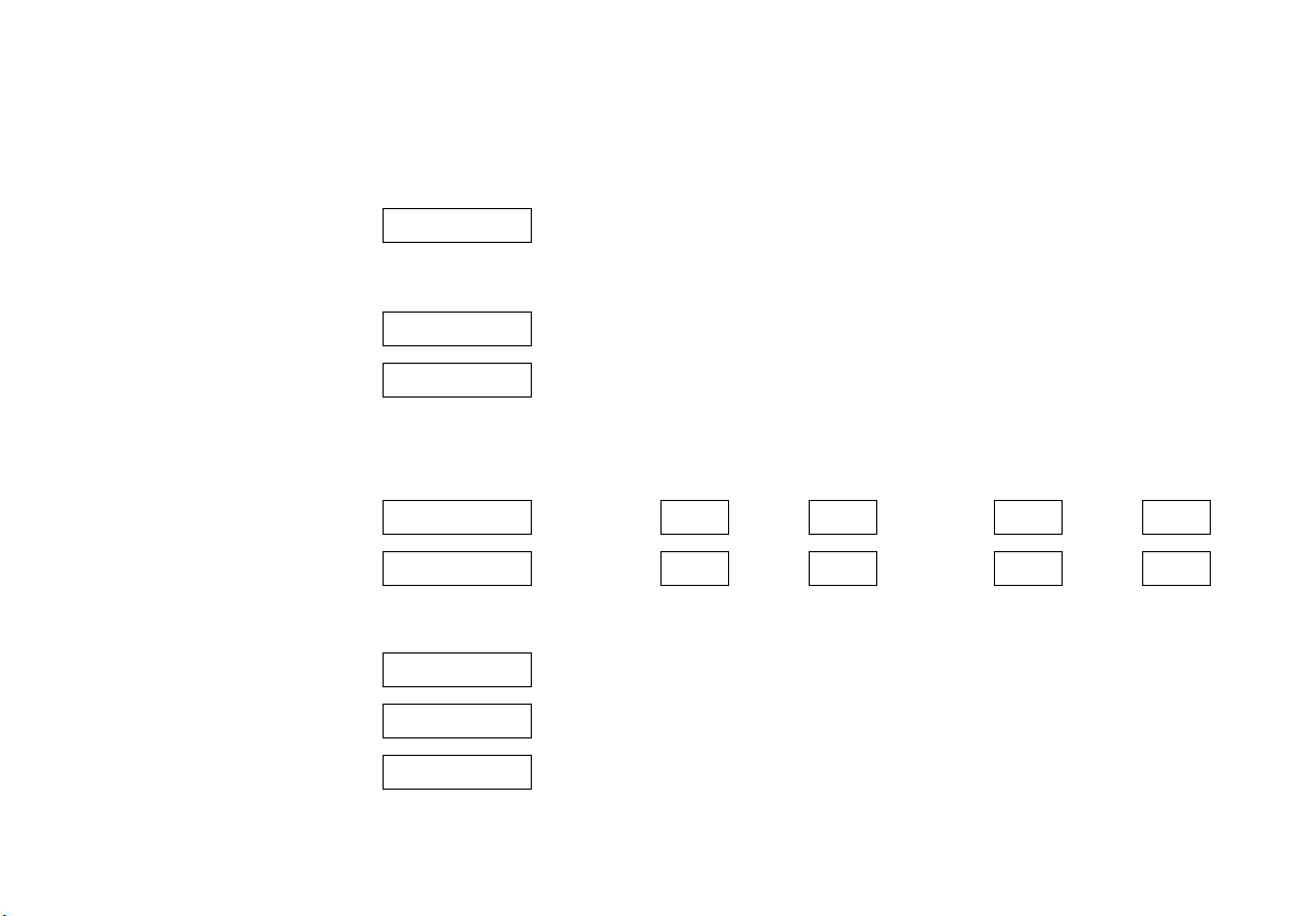
Child safety lock
The child safety lock for the sliding side
door 3 is located on its rearward facing
edge.
9 Warning
Use the child safety lock whenever
children are occupying the rear seats 3.
Disregard may lead to injuries or
endanger life. Vehicle passengers should
be informed accordingly.
To engage, turn knob from the vertical
position: anti-clockwise for right hand side
door or clockwise for left hand side door.
Door cannot then be opened from inside.
Page 42

Keys, doors, bonnet38
Note
The immobilizer does not lock the doors.
Therefore, after leaving the vehicle, always
lock it and switch on the Vauxhall alarm
system 3.
The Car Pass contains all the vehicle’s data
and therefore must not be kept in the
vehicle.
Have your Car Pass ready to hand when
consulting a Vauxhall Authorised Repairer.
Electronic immobilizer
The system checks whether the vehicle may
be started using the key that has been
inserted. If the key is recognised as
"authorised" the vehicle can be started.
The check is carried out via a transponder
housed in the key.
The electronic immobiliser is automatically
activated when the key is removed from
the ignition switch.
Control indicator for immobilizer
The control indicator lights up when the
ignition is switched on then goes out.
If the control indicator flashes rapidly after
the ignition is switched on, there is a fault in
the immobilizer system.
z Turn ignition off and remove key,
z wait approximately two seconds,
z then repeat starting procedure.
If the control indicator fails to extinguish,
try to start the engine using the spare key.
Obtain assistance from a workshop. We
recommend that you consult your Vauxhall
Authorised Repairer.
Page 43

Radio frequency remote control
The remote control is used to operate the
central locking system 3.
Depending on model the vehicle may use a
remote control with two or three buttons
(selective door locking).
The remote control has a range of approx.
3 metres. The range may be reduced
owing to shadowing and reflection of the
radio waves. To operate the remote
control, direct the remote control unit at
the vehicle.
3
Keys, doors, bonnet 39
Central locking system 3
see page 41.
Mechanical anti-theft locking system 3
see page 43.
Vauxhall alarm system 3
see page 43.
For your convenience we recommend that
the central locking system is always
operated using the remote control unit.
Treat the remote control unit with care; it
should be protected against moisture and
should not be operated unnecessarily.
Page 44

Keys, doors, bonnet40
Note
If the central locking system 3 cannot be
operated with the remote control, this may
be due to the following reasons:
z The remote control is out of range.
z The battery voltage of the remote
control is too low. Change the battery in
the remote control unit.
z The remote control has been operated
too many times in succession outside the
vehicle’s reception range (e.g. at too
great a distance from the vehicle).
The remote control must be
reprogrammed, we recommend your
Vauxhall Authorised Repairer.
z Interference from higher power radio
waves from other sources.
Lock or unlock the doors manually using
the key or central locking switch. Manual
locking does not operate the central
locking system. Have cause of fault
remedied. We recommend that you consult
your Vauxhall Authorised Repairer.
Changing the battery in remote control
unit
Replace the battery in accordance with the
Service Booklet or when the range of the
remote control starts to become reduced.
Two function remote control unit:
Open the battery compartment by
inserting a coin into the slot and twisting.
Ensure the new battery is installed
correctly.
Replace the cover and press until it is fully
engaged.
Selective door locking remote control unit
Open the battery compartment by
removing the screw on the rear cover, then
inserting a coin into the slot and twisting.
Ensure the new battery is installed
correctly.
Replace the cover and press until it is fully
engaged, then replace and secure screw.
Make sure that you dispose of old batteries
in accordance with environmental
protection regulations.
Page 45

Central locking system
For front, side and back doors 3, tailgate 3
and fuel filler flap 3. With selective door
locking 3, the passenger compartment
and rear load compartment are locked
and unlocked separately.
To unlock - two function remote control:
Press c button on remote control unit:
z Hazard warning lights flash once.
z Doors are unlocked.
To unlock - selective door locking:
Press c button on remote control unit:
z Hazard warning lights flash once.
z Doors of the passenger compartment
only are unlocked.
3
To lock - two function remote control:
Press e button on remote control unit:
z Hazard warning lights flash twice.
z Doors are locked.
To lock - selective door locking:
Press e button on remote control unit:
z Hazard warning lights flash twice.
z Passenger compartment doors only are
locked.
Always ensure that the side door 3,
tailgate 3 or back doors are properly
closed before locking the vehicle with the
remote control.
9 Warning
For safety reasons, the vehicle cannot be
locked if the ignition key is in the ignition.
Manually locking or unlocking a door with
the key does not operate the central
locking system.
For manual operation of the fuel filler flap
- see page 101.
Keys, doors, bonnet 41
Rear load compartment doors/tailgate selective door locking
To unlock
Press G button on remote control unit.
If no door is opened within 30 seconds
(approximately) after the vehicle has been
unlocked by the remote control the vehicle
is re-locked automatically.
To lock
Press G button on remote control unit.
The rear load compartment doors /
tailgate are now locked.
Page 46

Keys, doors, bonnet42
Central locking switch 3
Use the central locking switch to lock or
unlock the doors from inside the vehicle.
Press e on the switch to lock or U on the
switch to unlock.
Automatic locking 3
The central locking system can be
activated to automatically lock the doors
as soon as a speed of approximately
4 mph (6 km/h) is reached.
To activate
With the ignition switched on, press e on
the central locking switch and hold for
approx. 5 seconds, until audible
confirmation is heard.
To deactivate
With the ignition switched on, press U on
the central locking switch and hold for
approximately 5 seconds, until audible
confirmation is heard.
Unlocking the door
The doors are unlocked by opening any
door from inside the vehicle or by
operating the central locking switch.
9 Warning
If a rear door is opened, it will
automatically be relocked when the
vehicle reaches a speed of approx.
4 mph (6 km/h).
Fault
In the event of a fault e.g. automatic
locking doesn’t take place, ensure all the
doors have been properly closed. Check to
ensure that the automatic locking function
has not been deactivated inadvertently. If
this is the case, switch the ignition off and
on again and reactivate the system as
described previously.
If the automatic locking function still fails to
operate we recommend that you contact
your Vauxhall Authorised Repairer.
9 Warning
If you decide on having the system active
(with the doors closed) whilst driving, it
may become difficult for those assisting
you in gaining access to your vehicle in
the event of an emergency.
Slam door locks 3
For certain Van models
door and back door locks are isolated for
added security.
Whilst the front doors are locked and
unlocked using the remote control key in
the normal way, the sliding side door and
back door can only be opened by manual
operation of the vehicle key.
1)
the sliding side
1)
Not available with deadlock option.
Page 47

Keys, doors, bonnet 43
Mechanical anti-theft locking
system
To lock:
All doors must be closed; press the e button
on the remote control unit again within 10
seconds after locking. Hazard warning
lights flash 5 times.
-orturn key in driver's door lock towards front
of vehicle again within 10 seconds after
locking, then turn it back to the vertical
position and remove.
Lock buttons 3 on all doors are positioned
such that doors cannot be opened.
3
9 Warning
Do not use the system if there are people
in the vehicle! The doors cannot be
unlocked from inside.
Vauxhall alarm system 3
The system monitors:
z Front and side doors.
z Back doors or tailgate 3, bonnet.
z Passenger compartment.
z Ignition switch.
z Siren power supply 3.
The remote control unit is used to operate
the Vauxhall alarm system.
To unlock:
Press c button on remote control unit.
Hazard warning lights flash once.
-orturn key in driver's door lock towards rear
of vehicle, then turn it back to the vertical
position and remove.
9 Warning
Unlocking is not possible in any other
way, so keep spare key to hand in a safe
place!
Page 48

Keys, doors, bonnet44
To activate
All doors must be fully closed; press the e
button on the remote control, the turn
signal indicators flash twice. If the turn
signal indicators do not flash on activation,
this may indicate that a door or the bonnet
is not fully closed.
To deactivate
Press the c button on the remote control,
the turn signal indicators flash once.
If the alarm has been triggered, the turn
signal indicators will not flash upon
deactivation.
When unlocking the vehicle using the key,
the alarm will sound; to deactivate, insert
the key and switch on the ignition.
Note
The Vauxhall alarm system cannot be
deactivated in any other way so keep a
spare key in a safe place.
Alarm
During a switch-on phase the sensors can
trigger a maximum of 10 times
1)
.
The alarm takes the form of:
z an acoustic signal (horn, 25 seconds)
and
z a visual signal
1)
(turn signal indicators,
25 seconds).
Passenger compartment monitoring
When the anti-theft alarm is activated, the
system automatically monitors the inside
of the vehicle for movement.
To disable the passenger compartment
monitoring, (for example if an animal is left
in the vehicle):
z Press and hold the e button on the
remote control.
z An audible beep will sound to confirm
that the passenger compartment
monitoring function is disabled.
The disable monitoring function will remain
until the alarm is deactivated or the doors
unlocked.
Alarm back-up system 3
The alarm system has a battery back-up
siren unit which, in the event of its power
supply being disconnected or
disconnection of the vehicle battery, will
sound for approx. 5 minutes on its internal
batteries.
If the vehicle battery has to be
disconnected it will be necessary to
deactivate the alarm system.
To stop the siren if activated, reconnect the
vehicle battery and press the rear c button
on remote control unit.
Sliding side doors 3
Open the door by pulling the outside
handle, or by pulling the interior lever to
the rear, then sliding the door rearwards.
To close the door, slide it fully forwards and
ensure it is fully closed.
The door can be locked or unlocked with
the remote control 3, the central locking
switch 3 or by the interior lock switch.
Ensure the side door is closed before
driving the vehicle.
1)
Varies from country to country on account of
national regulations.
Page 49

Keys, doors, bonnet 45
Back doors
The doors can be locked or unlocked with
the remote control 3 , the central locking
switch 3, or the key 3.
To open the left-hand back door pull the
outside handle. The door is opened from
inside the vehicle by pulling the interior
handle.
The right-hand rear door is released using
the lever (arrowed).
3
9 Warning
The rear lights may be obscured if the
rear doors are open and the vehicle is
parked on the roadside. You should
make other road users aware of your
vehicle, by using a warning triangle or
other equipment specified by your
country’s road traffic regulations.
The doors are retained in the 90º position
by locking stays.
To open the doors to 180º or further 3, pull
the door release handles and swing open
to the desired position.
9 Warning
Ensure extended opening doors 3 are
secured when fully opened.
Opened doors may slam closed due to
the force of the wind!
Always close the right-hand door before
the left-hand door.
Tailgate 3
To open: press button and lift tailgate to
fully open position.
In very cold climates, the opening
assistance provided by the tailgate
hydraulic struts may be reduced.
The tailgate can be locked or unlocked
with the remote control 3 , the central
locking switch 3.
9 Warning
Ensure there is adequate clearance both
above (at least 2.15 m) and behind when
opening tailgate.
Close tailgate using the interior strap.
Ensure tailgate is fully closed.
Page 50

Keys, doors, bonnet46
Bonnet release
To open the bonnet, pull the release lever
located on the left-hand side below the
instrument panel. The bonnet will then be
unlocked and will partially open. Return
release lever to its original position.
To open completely, locate the safety
catch, located slightly to the right of centre
- as viewed from the front - pull the catch
and lift the bonnet.
To hold bonnet in the open position, insert
the support rod, located on the underside
of the bonnet, into the slot provided.
Before closing bonnet, press the support
rod firmly into its retainers. Lower bonnet
gradually to be finally dropped by its own
weight.
Check that the bonnet is locked in position
by pulling at its front edge. If it is not locked
in position, repeat closing procedure.
Page 51

Seats, interior 47
Seats, interior
Seat position ....................................... 47
Head restraints ................................... 48
Rear seats 3........................................ 48
Load compartment net 3.................. 51
Load compartment cover 3 .............. 51
Lashing eyes 3 ................................... 52
Load anchorage rails 3 ..................... 52
Notes on loading the vehicle............. 53
Cigarette lighter ) 3.......................... 54
Ashtray 3 ............................................ 55
Drink holders....................................... 55
Over-cab storage area 3................... 55
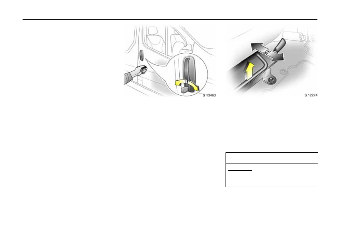
Seat adjustment
see page 2
Seat position
Adjust driver’s seat such that with the
driver sitting upright the steering wheel is
held in the area of its upper spokes with the
driver’s arms slightly bent.
The seat backrests must not be tilted too
far back (recommended tilting angle
approx. 25°).
9 Warning
Disregard can lead to injuries which could
be fatal. Vehicle passengers should be
informed accordingly.
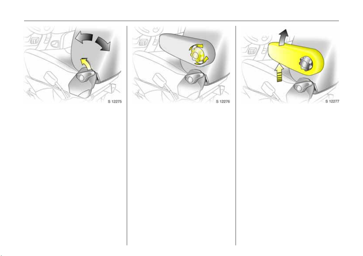
Head restraint position
The centre of the head restraint should be
at eye level. Adjust to highest position if
this is not possible for extremely tall
people, and adjust to lowest position for
extremely small people.
9 Warning
Disregard can lead to injuries which could
be fatal. Vehicle passengers should be
informed accordingly.
Setting – see page 4.
Page 52

Seats, interior48
Head restraints
Adjustments - see page 4.
To remove the head restraints, pull lock tab
and pull the restraint upwards.
Rear seats 3
On some variants, the rear passenger
compartment offers storage in the seat
trims.
To enable long items to be stored under
the seats the centre seat trim cover 3 can
be unclipped.
The load capacity can be increased further
by folding or removing the rear seats 3.
When folding or removing the rear seat
ensure the arm rests 3 are folded away in
their most upright position. Also remove
the lower seat trim side pockets 3
disconnecting them from the locating clips.
Page 53

Seats, interior 49
Rear seat access 3
To facilitate access to the rear seats, fold
the seat backrest forwards. If necessary
release the two-latch seat belt from its
buckles.
9 Warning
Ensure that the backrest returns to its
correct position and the seat belt buckles
engage securely - see page 58.
Folding seats 3
On some variants, the cargo area can be
increased by folding up the rear seats.
Remove the head restraints. Pull the side
handle to release the backrest and fold
forward onto the seatbase, if necessary
releasing the two-latch seat belts from their
buckles.
Release both locking bars at the rear base
of the seat by pulling rearwards.
Lift and fold the seat assembly, until the
seat frame rests in place.
9 Warning
When folding the seat use caution beware of moving parts. Ensure the seat
is secure when completely folded.
To return the folding seat to the upright
position, support the seat assembly and
release the bar by pulling the bar directly
towards you. Gradually lower the seat
assembly, allowing the rear support legs to
fold down. Lower the seat completely,
ensuring the rear support legs are located,
and latched. Raise the backrest, reinstall
head restraints and connect the seat belts.
9 Warning
When installing the seat, ensure that the
seat is properly located on the anchor
points and that the locking catches are
fully engaged, the backrest is returned to
the correct position and the seat belts are
engaged securely.
Page 54

Seats, interior50
Removable rear seats 3
On some variants, the cargo area can be
increased by removing the rear seats.
Release the seats by pressing down and
sliding forward the locking catch located
on the left and right hand seat mountings.
With both catches raised, push the seat
unit towards the rear and release them
from the floor anchor points. The seat can
then be lifted out.
The seats must be removed through the
sliding door only.
9 Warning
Removable seats are heavy! Do not
attempt to remove without assistance.
When installing the seats, ensure that the
seats are properly located on the anchor
points and that the locking catches are
fully engaged.
9 Warning
When re-installing seats always ensure
that the row with the folding access
seat B is positioned correctly in front of
the fixed seat row A.
If the seats are incorrectly positioned,
access for passengers is seriously
impeded. Disregard of these instructions
may endanger life.
Page 55

Load compartment net
The load compartment net can be fitted
behind the front or rear seats to separate
compartments when transporting luggage
or animals.
3
Installing (front or rear position)
Lift the covers to access the mountings,
insert the load compartment net rod into
the mounts and secure. Attach the straps
to the lashing eyes behind the front seats;
or to the rings on the rear seat frame, then
tension the straps.
Removing
Tilt strap length adjuster upwards and
unhook strap.
9 Warning
Loose objects in the luggage
compartment should be secured safely.
Seats, interior 51
Load compartment cover 3
To remove:
Lift cover and disconnect from the side
guides.
Notes on loading
See page 53.
9 Warning
Do not place any heavy or sharp objects
on the cover.
Loose objects in the load compartment
should be secured safely.
Page 56

Seats, interior52
z cargo can then be secured in position
using lashing straps 3 attached to the
anchorage point
The maximum load of each anchorage
point is 75 kg. To prevent the possibility of
exceeding this maximum, the use of
ratchet type lashing straps is to be
avoided.
9 Warning
Loose objects in the luggage
compartment should be secured safely.
Lashing eyes
Lashing eyes are mounted in the load
compartment to enable cargo to be
secured in position using lashing straps 3
or a luggage net 3.
The maximum force applied to the lashing
eyes should not exceed 5000 N at 30
3
°.
Load anchorage rails 3
Load anchorage rails 3 mounted in the
load compartment, provide adjustable
anchorage points for securing cargo.
z release centre pin of the anchorage
point, by pulling out against spring
tension
z slide the anchorage point to the required
location
z position the anchorage point directly
over the nearest suitable "locking hole"
z release the centre pin of the anchorage
point, ensuring the pin is located
correctly and the anchorage point is
securely locked
Page 57

Notes on loading the vehicle
z Heavy objects in the load compartment
should be placed as far forward as
possible. If objects are to be stacked, the
heavier objects should be placed at the
bottom. Unsecured objects in the load
compartment would be thrown forward
with great force in the event of heavy
braking, for example.
z Secure heavy objects with lashing straps
3 attached to the lashing points. If
heavy loads slip when the vehicle is
braked heavily or driven around a bend,
the handling of the vehicle may change.
z The warning triangle 3 and first aid kit 3
should always be freely accessible.
z No objects should be placed on the
instrument panel. They are reflected in
the glass, obstruct the driver’s view and
will be thrown through the vehicle in the
event of heavy braking, for example.
z No objects should be stored in any of the
airbag 3 inflation zones, as injuries may
be caused when the airbag is triggered.
z Bulky objects should not be transported
with the back doors open or ajar,
otherwise poisonous exhaust fumes may
enter the vehicle. In addition, the number
plate is only distinguishable and lit
correctly if the doors are closed.
Seats, interior 53
z Weights, payload and roof load - see
page 164.
z Driving with a roof load (see also page
95) increases the sensitivity of the vehicle
to cross-winds and has a detrimental
effect on vehicle handling owing to the
higher centre of gravity of the vehicle.
9 Warning
Disregard of these instructions may lead
to injuries or endanger life. Vehicle
passengers should be informed
accordingly.
Page 58

Seats, interior54
Cigarette lighter
With ignition switched on, press the
cigarette lighter. Heating up ceases once
element is glowing. Withdraw lighter.
Accessory socket
The socket for the cigarette lighter can be
used to connect electrical accessories when
the ignition is switched on.
) 3
The maximum power requirement of
electrical accessories must not exceed 120
watts.
Do not connect any current-delivering
accessories, e.g. electrical charging
devices or batteries.
Connected electrical accessories must
comply with the EC standard in terms of
electromagnetic compatibility
requirements laid down in DIN VDE 40 839,
otherwise vehicle malfunctions may occur.
The use of non-authorised accessories may
cause damage to the socket.
An additional accessory socket 3 is located
in the rear of the vehicle.
When the engine is not running using these
accessory sockets will cause the battery to
be discharged.
Page 59

Seats, interior 55
Ashtray
Removable to enable universal use for
driver or passengers.
To be used only for ash and not for
combustible rubbish.
3
9 Warning
Disregard of these instructions may lead
to injuries or endanger life. Vehicle
passengers should be informed
accordingly.
To open: lift up the cover.
To empty: remove the ashtray from the
drink holder recess and empty.
Drink holders
To use drink holders remove the ashtray
unit.
Over-cab storage area 3
The total weight in this compartment must
not exceed 30 kg.
Page 60

Safety systems56
Safety systems
Three-stage restraint system............. 56
Seat belts............................................. 57
Belt tensioners 3................................. 59
Airbag systems 3 ............................... 61
Child restraint systems 3 ................... 68
Exterior mirrors.................................... 74
Aspherical exterior mirror .................. 74
Sun visors............................................. 74
Head restraints ................................... 74
Safety accessories 3 .......................... 74
Three-stage restraint system
The system comprises
z three-point seat belts
z belt tensioners on the front seats
z airbag systems for driver and front
passenger 3.
The three stages are activated in sequence
depending on the seriousness of the
accident:
z The automatic seat belt locking devices
prevent the belt strap from being pulled
out and thus ensure that the vehicle
occupants are retained in their seats.
z The front seat belt buckles are pulled
downwards. As a result, the seat belts
are instantaneously tightened and the
occupants are made aware of the
deceleration of the vehicle at a very early
stage. This reduces stress placed on the
body.
z The airbag system is additionally
triggered in the event of a serious
accident involving a frontal impact and
forms a safety cushion for the driver and
front passenger 3. The side airbag
system 3 protects the occupants in the
front of the vehicle in the event of side-on
collisions.
9 Warning
The airbag system serves to supplement
the three-point seat belts and belt
tensioners. The seat belts must therefore
always be worn. Disregard of these notes
can lead to injuries which may be fatal.
Vehicle passengers should be informed
accordingly.
Be sure to read the detailed descriptions
of all the restraint systems on the
following pages!
Page 61

Seat belts
9 Warning
Always wear your seat belt - and that
means also in urban traffic and when you
are a rear seat passenger. It can save
your life!
Pregnant women too must always wear a
seat belt.
In the event of an accident, persons not
wearing seat belts endanger their fellow
occupants and themselves.
Seat belts are designed to be used by only
one person at a time. They are only
suitable for children aged up to 12 or
smaller than 150 cm if used in conjunction
with a child seat.
Three-point seat belts
The vehicle is equipped with three-point
seat belts with automatic retractors and
locking devices, allowing freedom of body
movement although the spring tensioned
belts are always a snug fit.
The belt has a “vehicle sensitive retractor”
which is designed to lock during heavy
acceleration or deceleration in any
direction.
Using the belts
Fitting the belt
Pull the belt out evenly from the retractor
and guide it across the body, making
certain that it is not twisted.
Insert the latch plate into the buckle. The
seat backrest must not be tilted back too
far; the recommended angle of inclination
is approx. 25°. The lap belt must not be
twisted and must fit snugly across the
body. Tension the belt frequently whilst
driving by tugging the diagonal part of the
belt.
Safety systems 57
9 Warning
On pregnant women in particular the lap
belt must be positioned as low as
possible across the pelvis in order to
prevent pressure on the abdomen.
Bulky clothing prevents the belt from fitting
properly. The belt must not rest against
hard or fragile objects in the pockets of
your clothing (e.g. ballpoint pens, keys,
spectacles) because these could cause
injury. Do not place any objects (e.g.
handbags) between the belt and your
body.
Page 62

Safety systems58
Upper anchorage point
height adjustment 3
z Do not adjust height whilst driving
z Slide adjuster up or down to desired
position
Adjust height such that the belt passes
over the wearer’s shoulder and rests
against the shoulder. It must not pass over
the neck or upper arm.
Removing the belt
To remove the belt, depress the red pushbutton on the buckle; the belt will retract
automatically.
Two-latch belt 3
Before fitting the belt, first insert lower
latch plate into the buckle on the outside of
the seat.
The belt can now be used in the same way
as a standard seat belt.
9 Warning
The seat belt will not be effective in the
event of an accident if the lower latch is
not correctly fitted.
When releasing the seat belt, ensure that
the central buckle is always released
before the buckle on the side of the seat.
Always remove the lower latch plate from
the outside buckle before removing seats
from the vehicle or to facilitate access to
the rear seats 3 - see page 48.
Page 63

Safety systems 59
Inspection of belts
Periodically inspect all parts of the belt
system for damage and to make sure they
are functioning properly. Have damaged
parts replaced. After an accident,
overstretched belts must be replaced by
new ones. We recommend consulting your
Vauxhall Authorised Repairer.
Do not perform any alterations on the
belts, their anchorages, the automatic
retractors or the belt buckles.
Make sure that belts are not damaged or
trapped by sharp-edged objects.
Actuation of belt tensioners
The belt tensioners must be replaced after
activation. We recommend that you
consult your Vauxhall Authorised Repairer.
9 Warning
The belt tensioners are operational only
when the control indicator is unlit.
The seat belts remain fully operational
even when the belt tensioners have been
actuated.
Belt tensioners 3
The seat belt systems incorporate belt
tensioners. In the event of a head-on or
tail-end collision the belt buckles are pulled
downwards; the diagonal and lap belts are
instantaneously tightened.
Page 64

Safety systems60
Belt tensioner control indicator
The seat belt tensioners are monitored
electronically together with the airbag, and
their operational readiness shown by the
control indicator in the instrument panel.
When the ignition is switched on, the
control indicator lights up, then
extinguishes. If it does not light up or if it
lights up during driving, there is a fault in
the airbag system or the belt tensioners
(see also page 64).
9 Warning
Have the cause of the fault remedied. We
recommend that you consult your
Vauxhall Authorised Repairer.
The system’s integrated self-diagnostics
allows faults to be quickly remedied. Have
Car Pass on hand when consulting a
Vauxhall Authorised Repairer.
Important
z Accessories not released for your vehicle
type and other objects must not be fixed
or placed within the action zone of the
belt tensioners as they may result in
injury if the belt tensioners are triggered.
z Do not make any modifications to the
components of the belt tensioners, as
this will render the vehicle unroadworthy.
9 Warning
Improper handling (e.g. removal or
installation) can activate the belt
tensioners – risk of injury.
z The belt tensioner and airbag system
control electronics can be found in the
centre console area. In order to avoid
malfunctions, do not store magnetic
objects in this area.
z We recommend that you have the front
seats removed by a Vauxhall Authorised
Repairer.
z The belt tensioners only actuate once.
Please replace belt tensioners that have
been triggered. We recommend that you
consult your Vauxhall Authorised
Repairer.
z When disposing of the vehicle, please
observe the applicable safety
regulations. Please have the vehicle
disposed of by a disposal company. We
recommend that you consult your
Vauxhall Authorised Repairer.
Page 65

Safety systems 61
When triggered, the driver’s airbag and
front passenger airbag 3 inflate in
milliseconds and form safety cushions for
the driver and front passenger. The
forward movement of the driver and front
passenger is checked and the risk of
injuries to the upper body and head
thereby substantially reduced.
z No impairment of view will occur,
because the airbags inflate and deflate
so quickly.
9 Warning
Airbag systems
Front airbag
The front airbag system is identified by the
word “Airbag” on the steering wheel and
above the glove compartment 3.
The front airbag system comprises:
z an airbag with an inflator in the steering
wheel, and a second one above the
glove compartment 3
z the control electronics with impact
sensor
z the airbag system control indicator v in
the instrument panel.
z Front passenger airbag deactivation 3
3
The front airbag system is triggered:
z depending on the severity of the
accident
z depending on the type of impact
z within the range shown in the illustration
z independently of the side airbag and
curtain airbag systems 3.
Examples:
z Impact against a non-yielding obstacle:
the front airbag is triggered at low
vehicle speed.
z Impact against a yielding obstacle (such
as another vehicle): the front airbag is
only triggered at a higher vehicle speed.
The front airbag system provides
optimum protection when the seat,
backrest and head restraint are correctly
adjusted. Adjust the driver's seat
according to the occupant's height such
that with the driver sitting upright, the
steering wheel is held in the area of its
upper spokes with the driver's arms
slightly bent. The passenger seat should
be as far back as possible, with the
backrest upright. Do not place the head,
body, hands or feet on the cover of the
airbag system.
Do not place any objects in the area in
which the airbags inflate.
The three-point seat belt must be
correctly fitted (see page 57).
6
Page 66

Safety systems62
The front airbag system will not be
triggered in the event of
z the ignition being switched off
z minor frontal collisions
z accidents in which the vehicle overturns
z collisions involving a side or rear impact
where it would not be of benefit to the
occupants.
9 Warning
Seat belts must therefore always be worn.
The front airbag system serves to
supplement the three-point seat belts. If
you do not wear your seat belt you risk
being seriously injured, or even thrown
from the vehicle, in the event of an
accident.
The belt helps to keep you in the correct
seating position, in which the front airbag
system will provide you with effective
protection in the event of an accident.
Side airbag 3
The side airbags are mounted on the
outboard sides of the front seat backrests
to protect the occupants in the event of a
severe side impact.
The side airbag system comprises:
z an airbag with inflator in the back of the
driver's and front passenger's seat
respectively
z the control electronics
z side impact sensors
z the airbag systems control indicator v in
the instrument panel.
The side airbag system will be triggered:
z depending on the severity of the
accident
z depending on the type of impact
z within the range shown in the illustration
z independently of the front airbag
system.
Page 67

When triggered the side airbag inflates in
milliseconds and forms a safety cushion for
driver and/or front passenger in the
respective door area. The risk of injury to
the upper body in the event of a side
impact is thereby substantially reduced.
9 Warning
There must be no objects in the area in
which the airbag inflates or in the area
between the seat backs and the vehicle
body. Do not place the hands or arms on
the covers of the airbag systems.
Important information - see page 66.
The three-point seat belt must be
correctly fitted - see page 57.
The side airbags will not be triggered in the
event of:
z the ignition being switched off,
z frontal collisions,
z accidents in which the vehicle overturns,
z collisions involving a rear impact,
z collisions involving a side impact outside
the passenger cell.
Curtain airbag 3
The curtain airbag system is identified by
the badge AIRBAG on the head lining trim.
The curtain airbag system comprises:
z an airbag with inflator in the roof frame
on the driver’s and passenger’s side
respectively,
z the control electronics,
z the side impact sensors,
z the airbag systems control indicator v in
the instrument panel.
Safety systems 63
The curtain airbag system will be triggered:
z depending on the severity of the
accident,
z depending on the type of impact,
z within the range shown in the illustration,
z together with the side airbag system,
z independently of the front airbag
system.
6
Page 68

Safety systems64
When triggered the curtain airbag inflates
within milliseconds and provides a safety
barrier in the head area on the respective
side of the vehicle. This reduces the risk of
injury to the head considerably in case of a
side impact.
9 Warning
There must be no objects in the area in
which the airbag inflates. Do not place
the hands or arms on the covers of the
airbag systems. Important information –
see page 66.
The three-point seat belt must always be
correctly fitted – see page 57.
The curtain airbags will not be triggered in
the event of:
z the ignition is switched off,
z frontal collisions,
z accidents in which the vehicle overturns,
z collisions involving a rear impact,
z collisions involving a side impact outside
the passenger cell.
9 Warning
Have the cause of the fault remedied. We
recommend that you consult your
Vauxhall Authorised Repairer.
The system's integral self-diagnosis facility
allows faults to be quickly remedied. Have
your Car Pass ready to hand when
consulting a Vauxhall Authorised Repairer.
Airbag control indicator v
The front airbag system, side airbag
system 3 and curtain airbag system 3 are
monitored electronically together with the
belt tensioners, and their operational
readiness shown by the control indicator in
the instrument panel. When the ignition is
switched on, the control indicator lights up
then extinguishes. If it does not light up, or
if it lights up during driving, there is a fault
in the airbag systems or the belt tensioners.
The systems might not be triggered in the
event of an accident.
Page 69

Safety systems 65
Front passenger airbag deactivation 3
Front and side airbag systems must be
deactivated if a child restraint system is to
be mounted on the front passenger seat.
The belt tensioners as well as all airbag
systems for the driver’s seat remain active
when the front passenger seat’s systems
are disengaged.
The switch for deactivating or activating
the airbag system is located on the front
passenger door.
The chosen setting remains active after the
ignition has been switched off. The control
indicator H for front passenger airbag
deactivation is located in the instrument
panel.
To deactivate
With the front passenger door open, press
switch in and rotate anti-clockwise to
"OFF" position.
The airbag systems for the front passenger
seat are now deactivated.
With the ignition switched on the control
indicator H will remain illuminated to
indicate deactivation. It is now safe to
place a child seat on the front passenger
seat.
6
Page 70

Safety systems66
To activate:
With the front passenger door open press
switch in and rotate clockwise "ON"
position. Front passenger airbag is now
activated. Upon switching the ignition on
the control indicator H will illuminate
briefly and then extinguish indicating the
passenger airbag is active.
If H remains illuminated in conjunction with
v indicates a fault within the system.
9 Warning
Have the cause of the fault remedied. We
recommend that you consult your
Vauxhall Authorised Repairer.
Important
z Accessories not released for your vehicle
type and other objects must not be
affixed or placed in the area in which the
airbags inflate, as they could cause
injury when the airbags are triggered.
z Do not place any objects between the
airbag systems and the vehicle
occupants; danger of injury.
z Do not stick or place anything on the
steering wheel, instrument panel, front
seat backrests in the vicinity of the
airbags and seat areas or cover them
with other materials.
z The airbag systems and belt tensioner
control electronics can be found in the
centre console area. In order to avoid
malfunctions, do not store magnetic
objects in this area.
z Use only a dry cloth or interior cleaner to
clean the steering wheel, instrument
panel, front seat backrests, roof frame
and seat area of the front passenger
seat. Do not use any aggressive cleaning
agents.
z Only protective covers which are
approved for your Vivaro with side
airbag 3 may be fitted on the front
seats. When fitting the protective covers,
make sure that the airbag units on the
outboard sides of the front seat
backrests are not covered.
z The airbag systems are triggered
independently of each other depending
on the severity of the accident and the
type of impact. The side airbag system 3
and the curtain airbag system 3 are
triggered together.
z Each airbag can be triggered only once.
Once triggered, an airbag must be
replaced without delay. We recommend
that you consult your Vauxhall
Authorised Repairer.
z The speeds, directions of movement and
deformation properties of the vehicles,
and the properties of the obstacle
concerned, determine the severity of the
accident and triggering of the airbags.
The degree of damage to your vehicle
and the resulting repair costs alone are
not indicative that the criteria for
triggering of the side airbag were met.
Page 71

Safety systems 67
z Do not perform any modifications to the
components of the airbag systems, as
this will render the vehicle unroadworthy.
9 Warning
The systems can be triggered abruptly
and cause injury if they are handled
improperly.
z We recommend having the steering
wheel, the instrument panel, all panelling
parts, the door seals, the handles and
the front seats removed by your
Vauxhall Authorised Repairer.
z When disposing of the vehicle, please
observe the applicable safety
regulations. Please have the vehicle
disposed of by a disposal company. We
recommend that you consult your
Vauxhall Authorised Repairer.
9 Warning
Child restraint systems as well as other
heavy objects must never be carried on
the lap of passengers; risk of fatal injury.
9 Warning
While using a child restraint system on
the front passenger seat, the airbag
systems for the front passenger seat must
be deactivated; if not, the triggering of
the front or side airbag poses the risk of
fatal injury to the child.
This is especially the case if backwardsfacing child restraint systems are used on
the front passenger seat.
The system for deactivating the front
passenger seat’s airbag systems is
indicated a sticker on the side of the
instrument panel, visible when passenger
door is open.
Page 72

Safety systems68
Child restraint systems
Vauxhall child restraint systems are
designed specifically for your vehicle and
thus provide optimum safety for your child
in the event of impact. The use of a
Vauxhall Child restraint system is therefore
recommended.
3
9 Warning
While using a child restraint system on
the front passenger seat, the airbag
systems for the front passenger seat must
be deactivated; if not, the triggering of
the front or side airbag poses the risk of
fatal injury to the child.
This is especially the case if backwardsfacing child restraint systems are used on
the front passenger seat.
Selecting the right system
Your child should be transported facing
rearwards in the vehicle as long as
possible. It is appropriate to change the
system when the child’s head can no longer
be properly supported at eye height. The
child’s cervical vertebrae are still very weak
and in an accident they suffer less stress in
the semi-prone rearward position than
when sitting upright.
Note
z Children under 12 years or under 150 cm
tall should only travel in an appropriate
child safety seat.
z When transporting children, use the child
restraint systems suitable for the child's
weight.
z Ensure that the child restraint system to
be installed is compatible with the
vehicle type.
z The covers of the Vauxhall child restraint
system can be wiped clean.
z Do not stick anything on the child
restraint systems and do not cover them
with any other materials.
z A child restraint system which has been
subjected to stress in an accident must
be replaced.
z Ensure that the mounting location of the
child restraint system within the vehicle is
correct.
z You should also observe the instructions
on installation and use supplied with the
child restraint system.
Page 73

The following Vauxhall child restraint
systems have been approved for
installation in your Vivaro:
Group, weight and age
1)
class
0
From birth - 10 kg,
Vauxhall
system
Baby Safe
0 - 10 months
0+
From birth - 13 kg,
0 - 2 years
I From 9 - 18 kg,
Duo Isofix
8 months - 4 years
II
from 15 - 25 kg,
Kid
3 years - 7 years
from 22 - 36 kg,
III
6 years - 12 years
1)
We recommend the use of each system
until the child reaches the upper weight
limit.
If child restraint systems of other
manufacture are to be installed, ensure
that they conform to the appropriate
safety regulations.
9 Warning
Disregard of these instructions may lead
to injuries or endanger life.
Safety systems 69
The country in which you are travelling
may prohibit child seat installation in
certain locations. Always observe local or
national regulations.
6
Page 74

70 Safety systems
Front seats - all variants
Group, weight and age class
Facing
direction
Single seat - front passenger
without
airbag
with airbag
- no side
airbag
0:
up to 10 kg or approx. 10 months
0+:
up to 13 kg or approx. 2 years
Rearward U U
I: 9 to 18 kg or approx. 8 months - 4 years Forward U U
II:
15 to 25 kg or approx. 3 - 7 years
III:
22 to 36 kg or approx. 6 - 12 years
1)
If adjustable, ensure seat is in its rearmost position. Make sure vehicle seat belt is as straight as possible between shoulder and upper achorage point.
2)
Ensure the front passenger airbag system is deactivated when installing a child seat in this position. See page 65.
U = Suitable for universal category restraint systems for use in this mass group, in conjunction with three-point seat belt.
UF = Suitable for universal category forward facing restraint systems for use in this mass group, in conjunction with three-point seat belt.
Forward U U
2)
2
2
X = Seat position not suitable for children of this mass group.
1)
with side
airbag
2
U
2
U
2
U
Bench seat - front passenger
without airbag with airbag
centre outer centre outer
X
U
X U
UF U UF U
UF U UF U
2
2
2
9 Warning
While using a child restraint system on the front passenger seat, the airbag systems for the front passenger seat must be deactivated; if
not, the triggering of the front or side airbag poses the risk of fatal injury to the child.
This is especially the case if backwards-facing child restraint systems are used on the front passenger seat.
Page 75

Combi - rear seats
Safety systems 71
Group, weight and age class
Facing
direction
0:
up to 10 kg or approx. 10 months
0+:
up to 13 kg or approx. 2 years
Rearward
I: 9 to 18 kg or approx. 8 months - 4 years Forward
II:
15 to 25 kg or approx. 3 - 7 years
III:
22 to 36 kg or approx. 6 - 12 years
U = Suitable for universal category restraint systems for use in this mass group, in conjunction with three-point seat belt.
L = Suitable only for specifically approved child restraints. Vauxhall has approved child restraint systems from the ’Baby-safe’, ’Duo-Isofix’ and ’Kid’
ranges. We recommend that you consult a Vauxhall Authorised Repairer.
+ = Seat with Isofix mounting available. When mounting Isofix, only Isofix child restraint systems that have been approved for the vehicle may be used.
We recommend that you consult a Vauxhall Authorised Repairer.
Forward U
2nd row bench seat 3rd row bench seat
Outer Centre Outer Centre
U
UU,+
U,+ XX
X
U
X
X
X
X = Seat position not suitable for children of this mass group.
Page 76

72 Safety systems
Tour - rear seats
Group, weight and age class
Facing
direction
0:
up to 10 kg or approx. 10 months
0+:
up to 13 kg or approx. 2 years
Rearward
I: 9 to 18 kg or approx. 8 months - 4 years Forward
II:
15 to 25 kg or approx. 3 - 7 years
III:
22 to 36 kg or approx. 6 - 12 years
1)
On left-hand drive 7 seater models (2 seat bench in 2nd row) it is permissible to install a universal child seat on the third seat row but only on the right
hand outboard side due to increased clearance in front of it.
U = Suitable for universal category restraint systems for use in this mass group, in conjunction with three-point seat belt.
L = Suitable only for specifically approved child restraints. Vauxhall has approved child restraint systems from the ’Baby-safe’, ’Duo-Isofix’ and ’Kid’
ranges. We recommend that you consult a Vauxhall Authorised Repairer.
+ = Seat with Isofix mounting available. When mounting Isofix, only Isofix child restraint systems that have been approved for the vehicle may be used.
We recommend that you consult a Vauxhall Authorised Repairer.
Forward U U X
2nd row bench seat 3rd row bench seat
Outer Centre Outer Centre
U
U
U,+ X
U,+ X
1)
1
1
X
X
X
X = Seat position not suitable for children of this mass group.
Page 77

Crew Cab - rear seats
Safety systems 73
Group, weight and age class
0:
up to 10 kg or approx. 10 months
0+:
up to 13 kg or approx. 2 years
I: 9 to 18 kg or approx. 8 months - 4 years Forward
II:
15 to 25 kg or approx. 3 - 7 years
III:
22 to 36 kg or approx. 6 - 12 years
= Seat position not suitable for children of this mass group.
X
Facing
direction
Rearward
Forward X
Rear bench seat
Outer Centre
XX
XX
X
Page 78

Safety systems74
Exterior mirrors
For the safety of pedestrians, the exterior
mirrors will swing out of their normal
mounting position in the event of an
accident-like impact.
Aspherical exterior mirror
Increases the field of vision. Slight
distortion means that it is somewhat
difficult to estimate the distance between
the vehicle and those behind it.
Sun visors
The sun visors are padded and can be
swung up and down and to the side for
protection of driver and passenger against
glare.
Head restraints
Do not attach objects or components that
are not approved for the Vivaro, to the
head restraints. These affect the protective
effect of the head restraints and can be
propelled through the vehicle in an
uncontrolled manner if the driver brakes
hard or an accident occurs.
Safety accessories 3
The wide range of Vauxhall accessories
allows you to equip your vehicle in
accordance with your own wishes. In
addition to safety accessories, items for
improving comfort and a complete range
of vehicle care products you will find many
articles which will be of great value to you
when needed.
All items are “Genuine Vauxhall Parts and
Accessories”, guaranteeing high quality
and an accurate fit.
Your Vauxhall Authorised Repairer will be
happy to advise you, for example with
regard to:
z Vauxhall child restraint system
z Tow rope
z Tow rod
z Jump leads
z Spare bulb kit
z Spare fuse kit
z Halogen fog lights
z Mud flaps
z Magnetic light
z Warning triangle
z First-aid kit (box)
z First-aid kit (cushion)
Page 79

Lighting 75
Lighting
Exterior lights ...................................... 75
Automatic dipped beam
activation 3......................................
Headlight range adjustment ?......... 76
Fog tail light r ................................... 77
Front fog lights > 3........................... 77
Reverse lights ...................................... 77
Door-to-door illumination 3 .............. 77
Interior light......................................... 77
Instruments, cigarette lighter ............ 78
Headlights when driving abroad ...... 78
76
Exterior lights
Turn light switch:
7 =Off
0 = Parking lights
P = Dipped or main beam
9
Dipped/main beam and headlight flash,
see page 12.
In positions 0 and 9, the tail lights and
number plate light are also illuminated.
Vehicles with daytime running lights 3:
When the ignition is on, the dipped beam is
on and the instrument illumination is
subdued.
The daytime running lights go off when the
ignition is switched off.
Follow the regulations of the country in
which you are driving when using daytime
running lights and front fog lights 3.
Driving abroad - see page 78.
Page 80

Lighting76
Automatic dipped beam
activation 3
Dipped beam switches on or off
automatically when the engine is running
based on the outside light conditions.
The exterior lights switch off when the
ignition is switched off.
To activate:
1. Switch on the ignition.
2. Turn light switch to 0 and return 7.
3. Repeat stage 2 within approximately 5
seconds.
This action is confirmed with a double
audible warning.
To deactivate:
1. Switch on the ignition.
2. Turn light switch to 0 and return 7.
3. Repeat stage 2 within approximately 5
seconds.
This action is confirmed with a single
audible warning.
For reasons of safety it is advisable to have
the automatic dipped beam function
activated.
Turn signals, hazard warning
flashers
See page 13.
Headlight range adjustment ?
With dipped beam switched on, adjust
headlight range to suit vehicle load.
Correct adjustment of the headlight range
reduces dazzle for other road users.
z No load = 0
z Loaded up to permissible
maximum weight = 4
Page 81

Lighting 77
Fog tail light
Front fog lights
Rotate switch, control indicators > and r
in instrument panel:
7 = Off
> = Front fog lights on
and r = Fog tail light and
>
r
> 3
front fog lights on
Reverse lights
Come on when reverse gear is engaged
and ignition is switched on.
Door-to-door illumination 3
The headlights are switched on and remain
illuminated for a short time after the
vehicle is parked.
To activate:
1. Switch off ignition.
2. Remove ignition key.
3. Open driver’s door.
4. Pull lever towards steering wheel.
The dipped beam illuminates for approx.
30 seconds. This action can be repeated up
to four times to a maximum period of two
minutes.
Switching on the ignition or rotating the
light switch cancels the function before the
lights automatically switch off.
Interior light
Operated by tilting the light lens. With the
light in its central position, the light
functions as a courtesy light and
illuminates when the front doors are
opened.
Once the front doors are closed, the
courtesy light goes out after a 15 second
delay.
The interior light extinguishes immediately
if the ignition is switched on.
Page 82

Lighting78
Load compartment lights
Van
Operated by tilting the light lens.
Combi / Tour / Crew Cab
Operated by tilting the light lens to one of
3-positions:
z On constantly
z Controlled by the function of the interior
light
z Off constantly
Instruments, cigarette lighter
Comes on when exterior lights are switched
on.
Headlights when driving abroad
The asymmetrical dipped beam increases
the field of vision on the near side of the
lane.
When driving in countries which drive on
the opposite side of the road, this causes
glare for oncoming traffic.
To avoid glare, conventional headlight
glasses must be provided with a black
cover strip. Consult a workshop. We
recommend your Vauxhall Authorised
Repairer.
Page 83

Windows 79
Windows
Door windows ..................................... 79
Electrically operated door windows 3 80
Sliding side windows 3....................... 80
9 Warning
Care must be taken when operating the
electrically operated windows. There is a
risk of injury, particularly for children, and
a danger that articles could become
trapped.
Vehicle passengers should be informed
accordingly.
Make sure that all vehicle occupants
know how to operate the windows
correctly.
Keep a close watch on the windows when
closing them. Ensure that nothing
becomes trapped in them.
Before leaving the vehicle, remove the
ignition key in order to prevent
unauthorized operation.
Door windows
The door windows can be operated with
the crank.
Page 84

Windows80
Electrically operated door
windows
The driver’s window is operated by the
switch located in the driver’s door.
To open the window, push the top of the
switch and to close, pull the top of the
switch. The window stops when switch is
released.
With the engine running: briefly pushing or
pulling the switch fully opens or closes the
driver’s side window. Briefly press the
switch again to stop the window during this
operation.
3
The passenger’s window is operated by a
switch in each front door.
To open the window, push the top of the
switch and to close, pull the top of the
switch. The window stops when the switch
is released.
9 Warning
Before leaving the vehicle, remove the
ignition key in order to prevent
unauthorized operation of the windows
(risk of injury).
Sliding side windows 3
To open, pull up catch and slide open.
To close, pull up catch and slide window
until catch engages.
Note: during window opening or closing,
keep the catch raised to allow the glass
sufficient clearance.
Page 85

Heating, ventilation 81
Heating, ventilation
Heating and ventilation system ........ 81
Rear air vents 3 .................................. 83
Heating the foot area ........................ 84
Window demisting and defrosting.... 84
Re-circulation button.......................... 85
Air conditioning system 3.................. 85
Rear air conditioning system 3 ......... 86
Heated rear windows 3, heated
exterior mirrors 3 ............................. 87
Heated front seats 3.......................... 88
Heating and ventilation system
Vauxhall air mixture system: by mixing cold
and hot air the temperature can be
regulated without delay and held
practically constant at all speeds.
Heating and ventilation controls
Air distribution switch
M To head area
L To head and foot area
K To foot area
J To defrosters and foot area
V To defrosters
The rotary switch can be set to any
intermediate position in order to adjust the
air distribution to suit personal
requirements.
Open the ventilation jets when the switch is
set to M or L.
Page 86

Heating, ventilation82
Temperature switch
To red Hotter
To blue Colder
Fan switch
Four speeds:
0 Off
4 High speed
The rate of air flow is determined by the
fan. The fan should therefore also be
switched on during driving.
Centre ventilation jets
Pleasant ventilation to the head area is
controlled by the position of the
temperature switch.
To open jets, turn regulating wheel:
Turn to left = Open
Turn to right = Closed
The air supply is increased by switching on
the fan.
The air flow can be directed as desired by
tilting and swivelling the fins.
Page 87

Heating, ventilation 83
Side ventilation jets
Depending upon the position of the
temperature switch, air will be directed into
the vehicle via these jets.
The jets are opened and closed by means
of the regulating wheel.
The air flow can be directed as desired by
tilting and swivelling fins.
To increase the air supply, switch on the
fan.
Door window defroster vents
Air distribution switch set to V or J: cold
or heated air will be directed onto the
windscreen and onto the door windows
(mainly in the area of the exterior mirrors).
Rear air vents 3
Operational when air distribution switch is
set to L, K or J.
Unheated or heated air will be directed into
the rear passenger compartment.
The air flow is biased towards the central
and right hand vents for optimum
distribution.
Ventilation
z Turn temperature switch to blue.
z Switch on fan.
z For maximum ventilation in head area:
set air distribution switch to M and open
all jets.
z For ventilation to foot area: set air
distribution switch to K.
z For simultaneous ventilation to head
and foot areas: set air distribution switch
to L.
Page 88

Heating, ventilation84
Heating
The amount of heat is dependant on the
engine temperature and is thus not fully
attained until the engine is warm.
For rapid warming of the passenger
compartment,
z Turn temperature switch to red.
z Switch on fan.
z Set the air distribution switch to the
desired position.
The comfort and general well-being of the
vehicle occupants are to a large extent
dependent on a correct setting of the
ventilation and heating.
Heating the foot area
z Turn temperature switch to red.
z Set the air distribution switch to K.
z Switch on fan.
Window demisting and defrosting
z Turn temperature switch to red.
z Switch on fan.
z Set air distribution switch to V.
z Open side ventilation jets as required
and direct them towards the door
windows.
z Close centre ventilation jets.
z Switch on heated rear windows.
For simultaneous warming of the foot area,
set air distribution switch to J.
Page 89

Re-circulation button
During ’normal’ operation, the heating and
ventilation and air conditioning systems
use outside air, however, to prevent fumes
from entering the vehicle when in
stationary traffic press the 4 button,
contol indicator illuminates and air will be
recirculated.
Recirculated air should only be used for
brief periods due to the gradual
deterioration in the air quality and increase
in humidity.
Air conditioning system 3
The air conditioning system is designed to
operate in conjunction with the heating
and ventilation system to provide
maximum comfort under any weather
conditions.
The air conditioning system cools the air
and removes moisture from it. It is
operational only in temperatures above
approx. +4 °C, with the engine running and
with the fan switched on:
Press AC button - control
indicator illuminates
Press AC button again = off
=on
Heating, ventilation 85
Once activated the air conditioning system
is operated via the normal heating and
ventilation controls.
To improve efficiency of the air
conditioning, always close the windows to
prevent chilled air from escaping.
Switching on the air conditioning will assist
in windscreen demisting.
In very hot temperatures, before switching
on the air conditioning, allow hot air to
escape from the vehicle by opening the
windows.
When the system is switched on, at least
one ventilation jet must be open so that the
evaporator does not ice up due to lack of
air movement.
When the air conditioning is on, fuel
consumption increases. Switch off the
system whenever it is not required.
Maintenance
To ensure efficient performance of the air
conditioning system, it must be switched on
once a month for a short time, irrespective
of the weather and time of year (possible
only when outside temperature is above
+4 °C).
Malfunctions in the system must not be
rectified by the owner; consult a workshop.
We recommend your Vauxhall Authorised
Repairer.
Page 90

Heating, ventilation86
Glove compartment cooler 3
Slide the control upwards to allow the air
conditioning system to also keep the
contents of the glove compartment cool.
Rear air conditioning system 3
The rear air conditioning 3 system cools
the air and removes moisture from it. It is
operational only in temperatures above
approx. +4 °C, with the engine running.
It is actuated in conjunction with the
driver’s compartment air conditioning:
Press AC button = on
Press AC button
again
=off
Rear passenger compartment
fan switch 3
The fan assists air flow to the passenger
compartment. Switching on the fan whilst
the air conditioning is actuated, will allow
conditioned air to be distributed.
The rate of air flow is determined by the
fan.
3 speeds:
0 Off
3 High speed
When the system is switched on, at least
one ventilation jet, located in the roof must
be open so that the evaporator does not
ice up due to lack of air movement.
Page 91

Heating, ventilation 87
Rear passenger compartment
heating
The fan assists air flow to the rear
passenger compartment via the rear air
vents.
3
The rate of air flow is determined by the
fan.
3 speeds:
0 Off
3 High speed
Heated rear windows 3,
heated exterior mirrors 3
Operates only with engine running.
Pushbutton Ü on instrument panel.
Press = on
Press again = off
Control indicator on pushbutton
illuminates when in use.
Turn off as soon as rear vision is clear. The
heating switches off automatically after
approx. 10 minutes.
Page 92

88 Heating, ventilation
Heated front seats
Pushbutton ß in trim panels of the seat.
Operate only with engine running.
Press = on
Press again = off
Seat heating is thermostatically controlled
and will automatically cease when the seat
temperature is sufficient. The control
indicator will illuminate when system is on,
not just when heating.
3
Page 93

Tecshift 89
Tecshift
Transmission display .......................... 89
Starting the engine............................. 89
Tecshift operation .............................. 90
Winter programme V......................... 91
Laden programme kg ........................ 92
Kickdown............................................. 92
Engine braking assistance ................. 92
Stopping the vehicle........................... 93
Parking ................................................ 93
Rocking the vehicle............................. 93
Manoeuvring the vehicle.................... 93
Fault W................................................ 94
Interruption of power supply ............. 94
The semi-automatic Tecshift transmission
permits manual (manual mode) or
automatic gearshifting (automatic mode),
both with fully automatic clutch control.
9 Warning
Disregard of these instructions may lead
to injuries or endanger life.
Transmission display
Shows the mode, programme and current
gear.
Starting the engine
Depress foot brake, turn on ignition.
If T is shown in the transmission display
the foot brake is not depressed. When "N"
is shown in the transmission display the
engine can be started.
It is not necessary to select the neutral "N"
position before starting. If a gear other
than "N" is selected, depress the foot brake
and there will be a short delay whilst the
transmission automatically shifts into
neutral.
Page 94

Tecshift90
Tecshift operation
The selector lever needs to be moved in the
appropriate direction only slightly. It then
returns to the centre position. Observe the
gear / mode indicator in the transmission
display.
Selecting neutral
Move the selector lever toward N.
Automatic mode
When the engine is started, Tecshift is in
automatic mode "A" is shown in the
transmission display.
To engage 1st gear depress foot brake and
move selector lever towards +.
The vehicle will begin to "creep" when the
foot brake is released without accelerating.
It is possible to start off quickly by releasing
the foot brake and accelerating.
In automatic mode the transmission shifts
to other gears automatically dependent on
driving conditions.
Manual mode
Manual gearshifting is possible in manual
mode. If the vehicle is in automatic mode,
manual mode can be selected by moving
the selector lever toward A/M. The current
gear will appear in the transmission
display.
To engage 1st gear depress foot brake and
move selector lever towards + or - and 1 will
appear in the transmission display.
Moving selector lever toward:
+ Shifts to a higher gear.
- Shifts to a lower gear.
If the engine speed is too low Tecshift will
automatically shift to a lower gear even in
Manual mode. This prevents the engine
from stalling.
If a higher gear is selected when the
running speed is too low, or a lower gear
when the speed is too high, no shift is
effected. This prevents the engine from
running at too low or too high revs.
Gears can be skipped by moving the
selector lever repeatedly at short intervals.
Page 95

Tecshift 91
In order to protect Tecshift at extremely
high clutch temperatures, an intermittent
audible warning may sound. In such cases
depress the foot brake, select "N" and
apply the handbrake allowing the clutch to
cool down.
If the vehicle is switched to manual mode
while winter programme is active, the
Winter programme is switched off.
Selecting reverse
Engage only when the vehicle is stationary.
With the foot brake depressed, move the
selector lever toward R. Reverse gear is
engaged and "R" appears in the
transmission display.
The vehicle begins to creep when the foot
brake is released. Accelerate gently to
move.
Winter programme V
In the event of difficulties starting-off on
slippery surfaces, press button V and V is
shown in the transmission display. Tecshift
switches to automatic mode and the
vehicle sets off in a suitable gear.
The Winter programme is switched off by:
z pressing button V again,
z turning off the ignition.
Page 96

Tecshift92
Engine braking assistance
Automatic mode
When driving downhill Tecshift does not
shift into the higher gears until a fairly high
engine speed has been reached. During
braking Tecshift shifts down to a lower
gear in good time.
Manual mode
To utilize the engine braking effect, select a
lower gear in good time when driving
downhill.
Laden programme kg
It is possible to use Laden programme in
both manual and automatic modes. In
both cases, the gear shifting patterns are
adapted automatically for carrying an
increased payload. Press button kg, Laden
programme will be selected and kg will
appear in the transmission display. Tecshift
will then select optimized gear shift
patterns.
The Laden programme is switched off by:
z pressing button kg again,
z turning off the ignition.
Kickdown
Accelerator pedal pressed past the
pressure point: below certain speeds, the
transmission shifts down into a lower gear.
Full engine power is available for
acceleration.
When the engine speed approaches its
upper limit, the transmission shifts to a
higher gear during kickdown even in
manual mode.
Without kickdown this automatic shift is
not affected in manual mode.
Page 97

Tecshift 93
Stopping the vehicle
In automatic or manual mode, once the
vehicle is stationary first gear engages
automatically and the clutch opens. In R,
reverse remains engaged.
When stopping on gradients engage
handbrake or depress brake pedal. To
prevent overheating of the clutch, an
intermittent, audible warning may sound
as a signal to depress the foot brake or
apply the handbrake.
Switch off engine if stopping for a lengthy
period, e.g. in traffic jams.
Parking
Before leaving the vehicle:
z engage handbrake,
z remove ignition key.
The most recently engaged gear (indicator
in transmission display) remains engaged.
With N, no gear is engaged.
When the ignition is switched off Tecshift
no longer responds to movements of the
selector lever.
If the ignition is not switched off, or the
handbrake has not been applied, an
intermittent audible warning may sound
upon opening the driver’s door.
Rocking the vehicle
If it becomes necessary to rock the vehicle
to free it from sand, mud, snow or a hole,
move the selector lever between R and A
(or + or -) in a repeat pattern while applying
light pressure to the accelerator pedal. Do
not race the engine and avoid sudden
acceleration.
This applies only in exceptional
circumstances mentioned above.
Manoeuvring the vehicle
To manoeuvre the vehicle back and forth
during attempts to park or in garage
entrances, the creeping movement can be
utilized by releasing the foot brake.
Never actuate the accelerator and brake
pedals simultaneously.
In order to protect Tecshift at extremely
high clutch temperatures, an intermittent
audible warning may sound. In such cases
depress the foot brake, select "N" and
apply the handbrake allowing the clutch to
cool down.
Page 98

Tecshift94
W
Fault
If a fault occurs in Tecshift, control
indicator W will be shown in the
transmission display.
You can continue driving, provided you
drive with care and anticipation. Consult a
workshop to have the cause of the fault
eliminated. We recommend your Vauxhall
Authorised Repairer. The system's integral
self-diagnosis facility allows faults to be
quickly remedied.
Interruption of power supply
The clutch is not disengaged if the vehicle
battery is discharged and a gear has been
selected. The vehicle cannot move.
If the battery is flat, start the vehicle using
jump leads - see page 126.
If the cause of the interruption to the power
supply is not a discharged battery, consult
a workshop. We recommend your Vauxhall
Authorised Repairer.
Page 99

Driving hints 95
Driving hints
The first 600 miles (1000 km)
Drive your vehicle at various speeds. Do
not use full throttle. Never allow the engine
to labour at low revs.
Make good use of all gears. Depress the
accelerator pedal a maximum of around
three quarters of the available pedal travel
in all gears and drive ranges.
Do not drive faster than three quarters of
maximum speed.
The information concerns the engine and
parts of the power train, e.g. the final drive.
Never coast with engine not
running
Many units will then not function (e.g. turn
signal indicators, brake servo unit, power
steering, airbag system). Driving in this
manner is a danger to yourself and others.
Brake servo unit
With the engine not running the brake
servo unit is no longer effective once the
brake pedal has been depressed once or
twice. The braking effect is not reduced but
substantially greater foot pressure is
necessary to stop the vehicle.
Power steering
Never leave the steering wheel on full lock
when the vehicle is stationary as this may
damage the power steering pump.
If the power steering should fail - e.g. when
the vehicle is being towed with the engine
switched off - the vehicle can still be
properly steered but considerably greater
effort is necessary.
Driving in mountainous terrain or
with caravan/trailer
Electrically driven fan: The fan cooling
capacity is not dependant on engine
speed. It is not necessary, therefore, when
driving uphill to shift down into a lower
gear if the vehicle can climb in a higher
gear.
Driving with a roof load
Do not exceed the permissible roof load.
For safety reasons, distribute the load
evenly and secure it tightly with straps so
that it cannot slip. Set the tyre inflation
pressure to the value given for full load. Do
not drive faster than 75 mph (120 km/h).
Check and retighten straps at frequent
intervals.
Page 100

Driving hints96
Switching off the engine
If the engine temperature is very high, e.g.
after driving in mountainous terrain: allow
the engine to idle for approximately two
minutes in order to prevent heat
accumulation.
When you switch off, fans in the engine
compartment may continue running for a
time to cool the engine.
Vehicles with turbocharged
engine
After running at high engine speeds or high
engine loads, operate the engine briefly at
a low load or run in neutral for approx. 30
seconds before switching off in order to
protect the turbocharger.
Save energy – more miles
Please observe the running-in hints on the
previous page and the tips for energy
saving on the following pages.
Good, technically correct and economical
driving ensures maximum durability and
performance for your vehicle.
Overrun
The fuel supply is automatically shut off
during overrun, e.g. when the vehicle is
being driven down long gradients or during
braking. To enable the overrun cut-off to
come into action, do not accelerate or
declutch during overrun.
Engine rpm
Under all driving conditions drive in a
favourable engine speed range.
Warming up
Allow the engine to warm up while driving.
Do not warm it up by letting it run at idling
speed. Do not apply full throttle until the
engine has reached operating
temperature.
After a cold start, Tecshift 3 do not shift
into higher gears until higher engine
speeds have been reached. This allows the
catalytic converter to quickly reach the
temperature required for optimum
pollutant reduction.
Correct gear selection
Do not race your engine whilst in neutral or
with a low gear selected. Driving too fast in
individual gears or drive ranges as well as
stop-and-go traffic increase engine wear
and fuel consumption.
Change down
When decreasing speed shift down into the
next lowest gear. Do not slip the clutch with
a high-revving engine. This is especially
important when hill climbing.
Clutch operation
Always depress the clutch pedal hard to
the floor to prevent shifting difficulties and
transmission damage. There must be no
mats in the area of the pedals.
When driving do not use the pedal as a
foot rest; this will cause substantial clutch
wear.
Pedals
Do not place any objects in the foot well
which could slip under the pedals and
inhibit the pedal travel.
To ensure the pedal travel is uninhibited,
there must be no mats in the area of the
pedals.
Battery care whilst driving
When driving slowly or when the vehicle is
stationary, e.g. in slow urban traffic, stopand-go traffic or traffic jams, turn off all
unnecessary electrical loads where
possible (heated rear window, auxiliary
headlights etc.).
When starting the engine, depress the
clutch pedal so that transmission
resistance is eliminated and the starter
motor and battery are relieved.
 Loading...