

Page 1
VECTRA
Operation, Safety and Maintenance
Owner’s Manual
Page 2

VAUXHALL Vectra
Operation, Safety, Maintenance
Page 3

Data specific to your vehicle
Please en ter yo u r veh icle ’s data he re to ke ep it ea sily acces sible.
This information is available under the section "Technical da ta" as we ll as on the identification plate and in the Service Booklet.
Fuel
De sign atio n
Engine oil
Grade
Viscosity
Tyre pressure
T y re si ze wi th up to 3 pe opl e wi th full loa d
Su mmer t yres Fro nt Rea r Fro nt Rea r
Wint er t yres Fro nt Rea r Fro nt Rea r
Weights
Permissible Gross Vehicle
Weight
– EC kerbweight
=Loading
Page 4

Your Vec tra
is an intelligent combination of forwardlooking technology, impressive safety,
environmental friendliness and economy.
It now lies with you to drive your vehicle
safely and ensure that it performs
perfectly. This Owner’s Manual provides
you with all the necessary information to
that end.
Make sure your passengers are awa re
of the possible risk of accident and injury
which may result from improper use of the
vehicle.
You must always comply with the specific
laws of the c ountry that you are travelling
through. These laws may differ from the
information in this Owner’s Manual.
When instructed to co n sult a w ork shop,
we recommend that you consult your
Vauxhall Authorised Repairer.
All Vauxhall Authorised Repairers provide
first-class service at reasonable prices.
You will receive quick, reliable and
individual service.
Experienced mechanics, trained by
Vauxhall, work a ccording to specific
Vauxhall instructions.
The Owner’s Manual should always be kept
in the vehicle: Ready to hand in the glove
compartment.
Make use of the Owner’s
Manual:
z The "In brief" section will give you an
initial overview.
z The table of c ontents at the beginning of
the Owner’s M anual and within the
individual chapters will show y ou where
everything is.
z Its index will help you find what you
want.
z It will fa miliarise you with the
sophisticated technology.
z It will incre ase your pleasure in your
vehicle.
z It will help you to handle your vehicle
expertly.
The Owner’s Manual is designed to be
clearly laid-out and easily understood.
This symbol signifies:
6 Continue read ing on ne xt page.
3 The asterisk signifies equipment not
fitted to all vehicles (model variants,
engine options, models specific to one
country, optional equipment, Genuine
Vauxhall Parts and Accessories).
9 Wa rn ing
Text marked 9 Warning provides
information on risk of accide nt or injury.
Disregard of the instructions may lead
to injuries or endanger life. Inform your
passengers accordingly.
Yellow arrows in the illustrations serve as
points of reference or indicate some action
to be performed.
Black arrows in the illustrations indicate a
reaction or a second action to be
performed.
Direc tional data, e.g. left or right, or front
or back, in the descriptions always relate to
the direction of travel.
Thank you for choosing a Vauxhall. We
wish you many hours of plea surable
driving.
Your Vauxhall Team
Page 5

Page 6

Contents
Commitment to customer
satisfaction:
Our ai m: to k eep you happy with your
vehicle. All Vauxhall Authorised Repairers
offer first-class service at competitive
prices. Experienced, factory-trained
technicians work according to factory
instructions. Your Authorised Repairer can
supply you with GEN UINE VAUXHALL-
APPROVED PARTS, which have undergone
stringent quality and precision checks, and
of course useful and attractive
VAUXHALL-APPROVED ACCESSORIES.
Our name is your guarantee!
For d eta ils of the
Vauxhall Au thorised Rep aire r Netw ork,
please ring this number; 0845 090 2044
In b rief .. ......... ......... ......... ......... ......... ........ . 2
Keys, doors, w in dows, sunroof ... ......... .. 26
Seats, interior ..... ........ ..... ......... .... ......... .. 50
Instruments, controls ...... ......... ......... ...... 98
Ligh ting ..... ......... .... ......... .... ......... ......... 128
Infotainment system . ......... ......... ......... 137
Clim ate c on trol ...... ......... ......... ......... .... 140
Driving an d operation ... ......... ......... .... 168
Self-help, vehicle care ........ ..... ......... .... 228
Service , mainte na nce ......... ......... ......... 268
Te chnical data ...... .... ......... ..... ......... .... 282
Index . ......... ......... ........ ......... ......... ......... 314
Page 7
2In brief
In brief
To unlock and open vehicle:
Press bu tton
6 Door locks, child safety locks –
see page 41,
keys – see page 26,
electronic immobiliser – see pag e 27,
re mo t e c o nt ro l – see page 28,
central locking – see p age 30,
mechanical a nti-theft locking system 3 –
see page 30,
Vauxhall alarm system 3 – s ee pag e 38.
q , pull door handle
To unlock an d open the luggag e
compartment:
Press button
q on remote con trol,
press button on boot lid/tailgate
and for Estate, pull catch
under handle
6 Remote control – see page 28,
central locking – see page 30,
Vauxhall alarm system 3 – see page 38,
electrically op erat ed tailgate 3 –
see page 35.
Page 8
3In brief
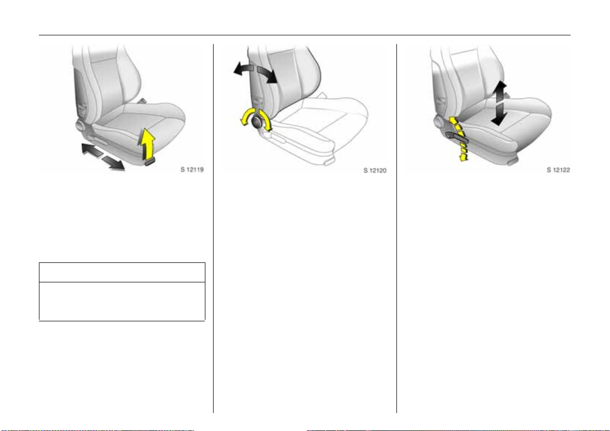
To adjust front seats:
Pull handle, slide seat,
release handle
6 Seats – see page 50,
seat position – see page 52,
electrically adjustable front seats –
see page 52.
9 Wa rning
Important: Do not sit nearer than
10 in ches (25 cm ) from the s tee ring
wheel, to permit safe airbag deployment.
To adjust front seat backrests:
Turn handwheel
Move seat backrest to suit seating position.
Do not lean on seat b ackrest whilst
adjusting it.
6 Seats – see page 50,
seat position – see page 52,
foldingdow n front passenger’s seat
backrest – see page 66,
electrically adjustable front seats –
see page 52.
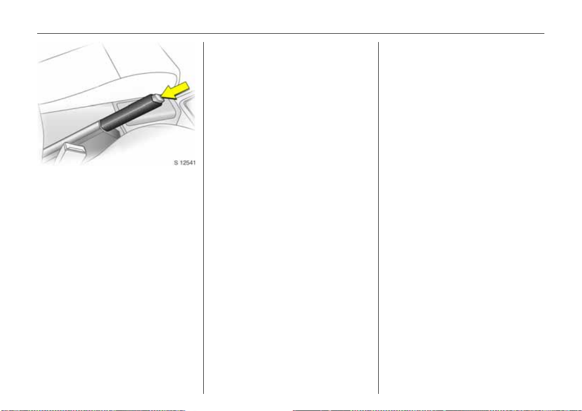
To adjust fron t seat heig ht 3:
Operate lever on outboard side of
seat
Pump action of lever
Upwa rds: Seat higher
Downwards: Seat lower
6 Seats – see page 50,
seat position –see page 52,
electrically adjustable front seats –
see page 52.
Page 9
4In brief
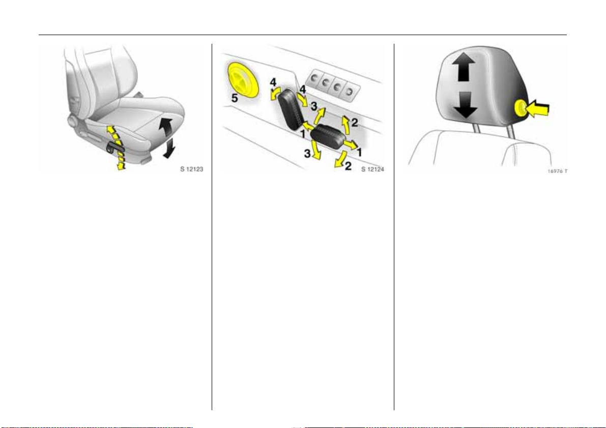
Adjusting front seat inclination 3:
Operate front lever on outboard
side of seat
Pump action of lever
Upwards: Seat steeper
Downwards: Seat flatter
6 Seats – see page 50,
seat position – see page 52,
electrically adjustable front seats –
see page 52.
Electric seat adjustment 3 :
Operate switch on outboard side
of seat
1 Adjusting the longitudinal position
2 Adjusting the inclination
3 He ig ht adjus tme nt
4 Seat back rest adjustment
5 Lumbar support 3
6 Seats – see page 52,
seat position – see page 52,
electrically adjustable front seats –
see page 52.
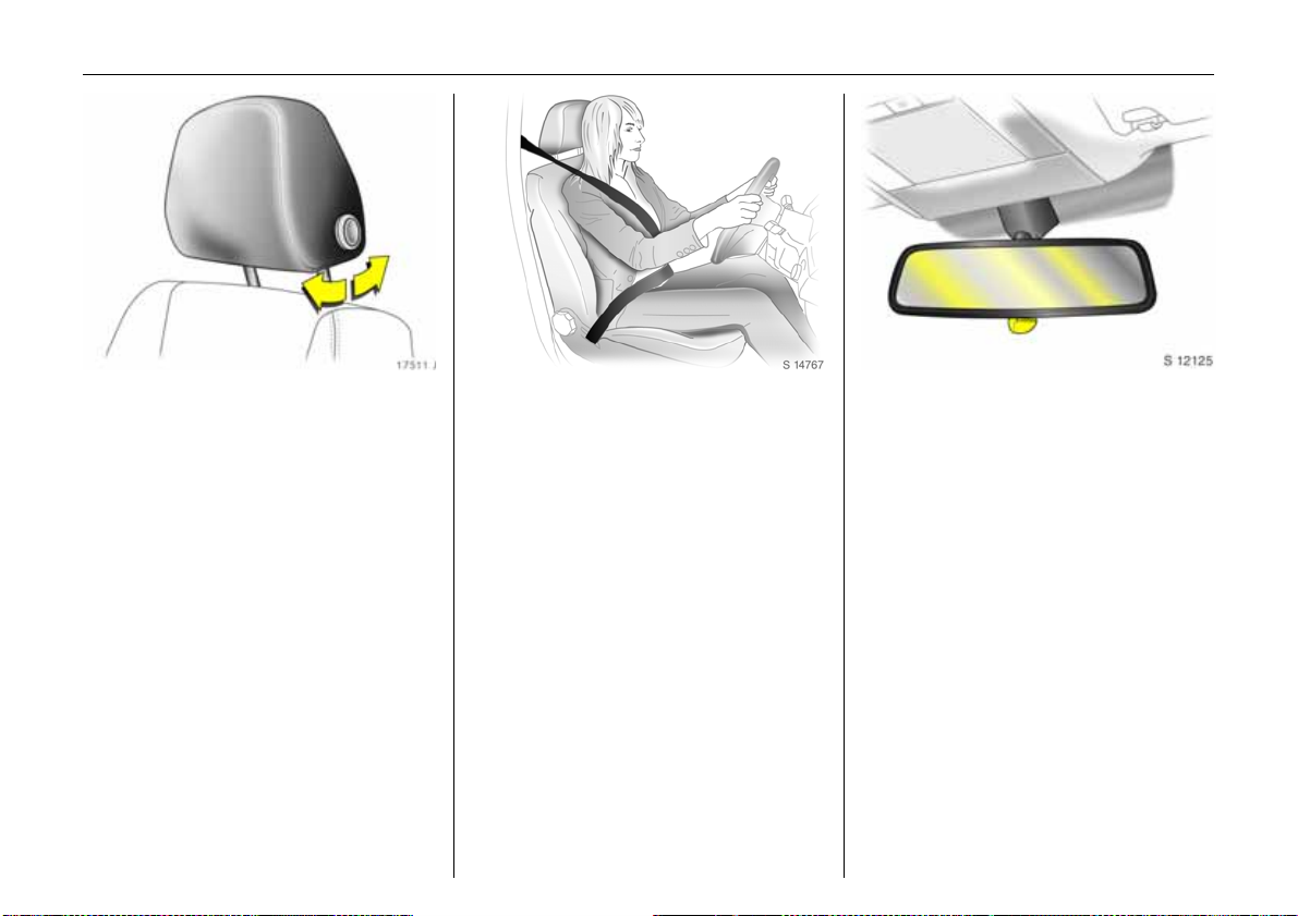
To adjust head restraint height 3
of front and outboard rear sea ts:
Press button to release,
adjust height, engage in position
6 Head restraints – see page 55,
head restraint position – see page 56,
rear head restra ints – see p age 55.
Page 10
5In brief
To adjust head restra int ang le 3
of front and outboard rear seats:
Swivel bottom edge of head
restraint forwards or backwards
6 Head restraints – see page 55,
head restraint position – see pag e 56,
rear head restraints – see page 55.
To apply seat belt:
Pull out seat belt smoothly from
inertia reel, guide it over the
shoulder and engage in the
beltbuckle
The seat b elt must not be twisted at any
point. The lap belt must lie snugly against
the body. The backrests must not be tilted
back too far (recommended maximum
tilting a ngle approx. 25°).
To release belt, press red button on be lt
buckle.
6 Three-point seat be lts – see page 72,
airbag systems 3 – see page 81,
seat position – see page 52.
Adjusting interior mirror:
Swivel mirror housing
Swivel lever on underside of mirror housing
to reduce dazzle at night.
6 Mirror – see page 44,
automatic anti-dazzle interior mirror 3 –
see page 44.
Page 11
6In brief
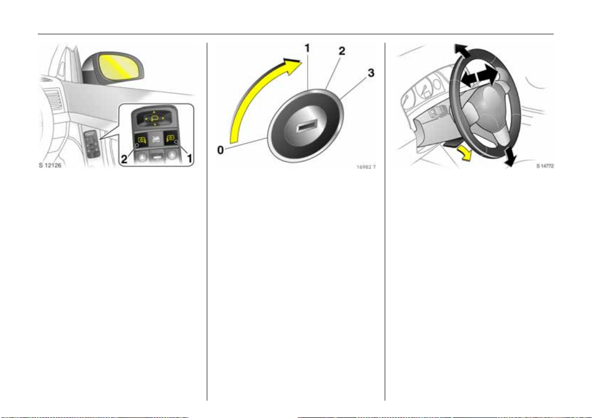
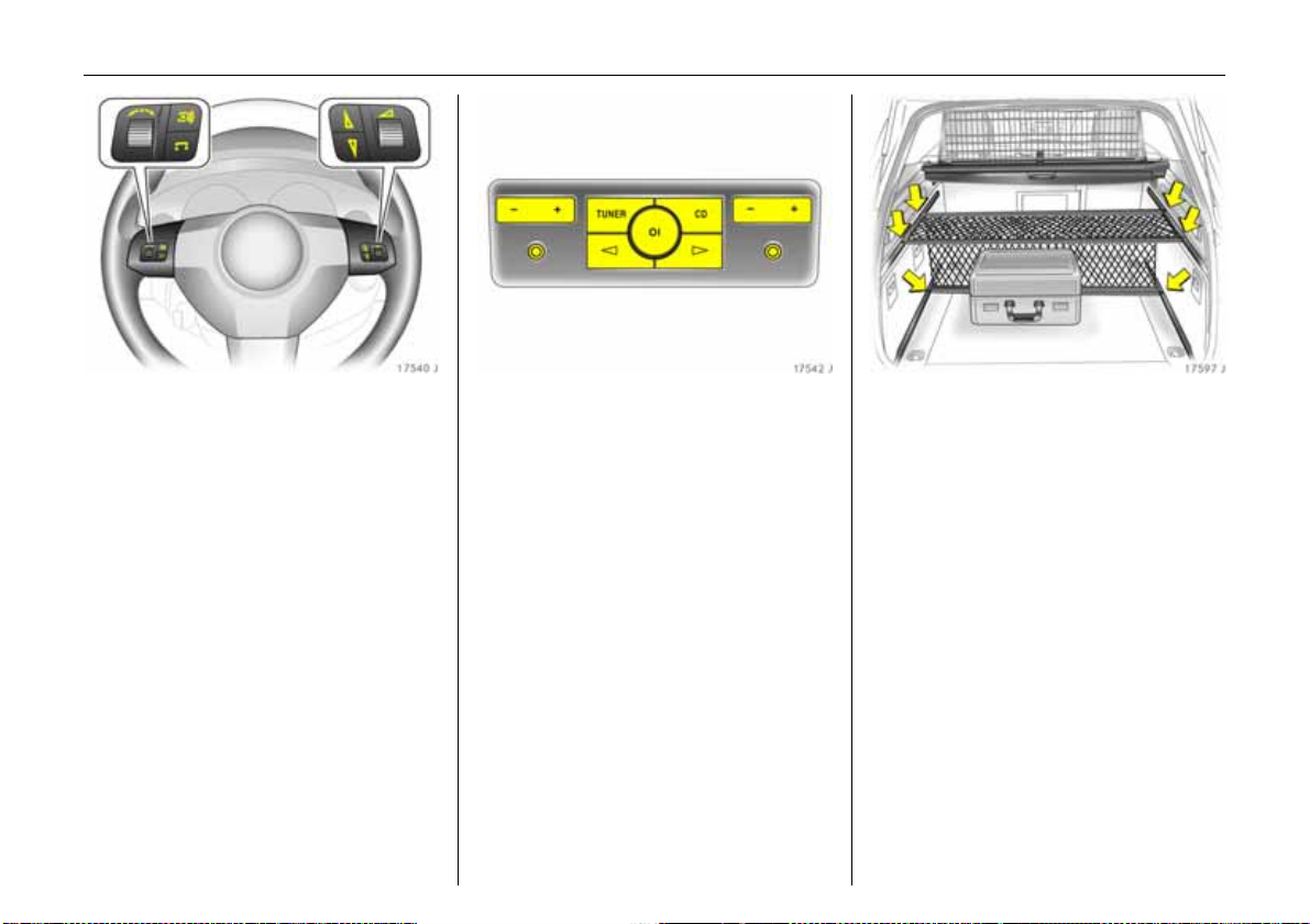
To adjust exterior mirrors:
Four-way switch in driver’s door
If the outer mirror switch (1) is pres se d, the
four-way switch operates the driver’s and
front passenger’s mirrors 3 , and if the inner
mirror switch (2 ) is pressed, it only operates
the front passenger’s mirror.
6 Mirrors – see page 43,
aspherical exterior mirrors 3 – see pa ge 43,
automatic anti-dazzle exterior m irrors 3 –
see page 43,
heated exterior mirrors – see page 13,
electric seat adjustment 3 – see page 54.
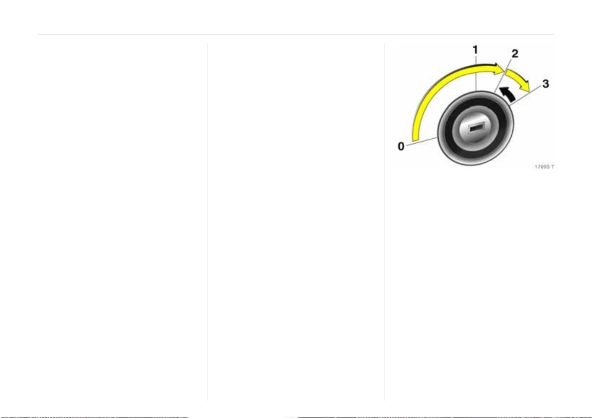
Steering column lock and ignition:
Turn key to position 1.
Mo ve steering wheel slightly to
release steering column lock
Positions:
0 = Ignition off
1 = Steering free, ignition off
2 = Ignition on, for diesel engines:
Preheating
3=Starting
6 Starting – see page 15,
electronic immobiliser – see pag e 27,
parking the vehicle – see page 16.
Steerin g wh eel adjustment 3 :
Move lever down,
adjust height and distance,
move lever up,
eng age
Adjust steering wheel only when vehicle is
stationary and steering column lock is
released.
6 Airbag systems 3 – see page 81.
Page 12
7In brief
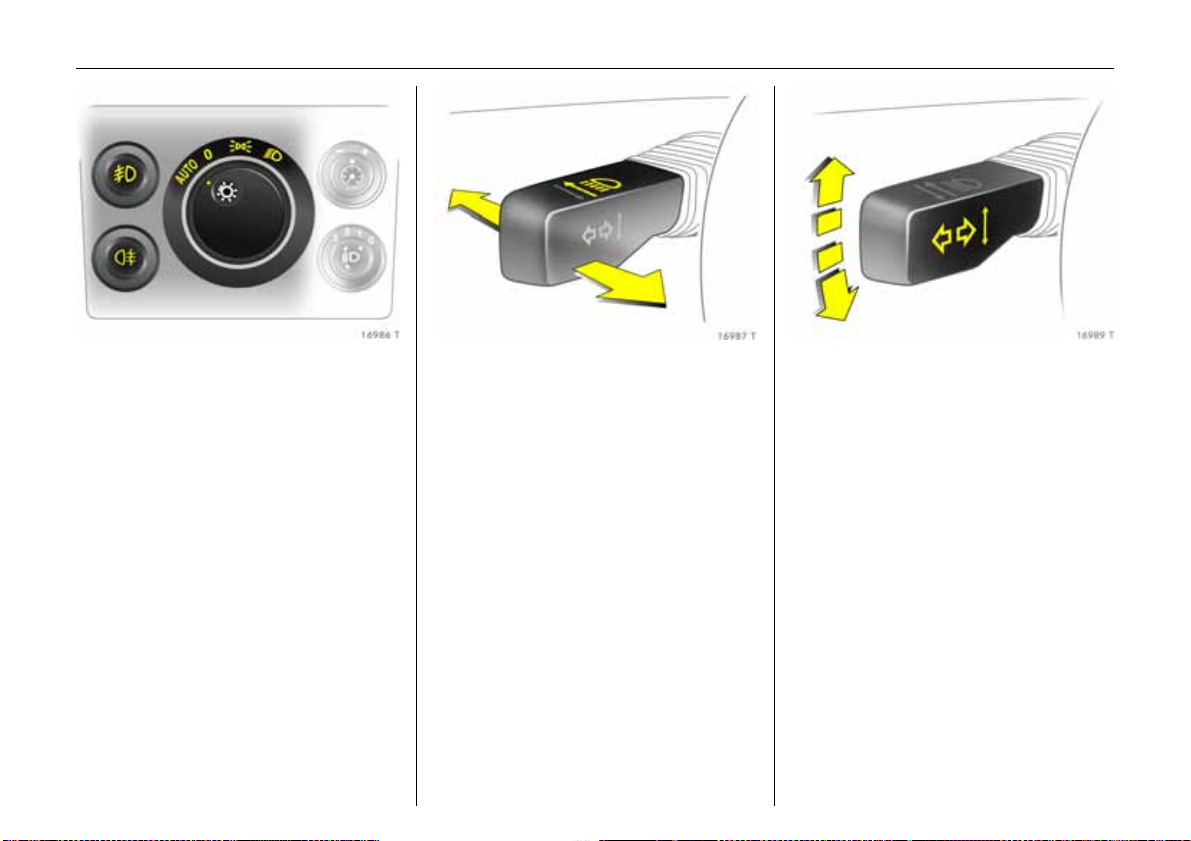
Turn light switch:
7 =Off
8 = Parking lights
9 = Dipped or main beam
AUTO = Automatic dipp e d
beam activation
3
Press button:
> = Front fog lights 3
r = Fog tail light
6 Lighting – see page 128,
headlight control indicator –
see page s 100, 126, 128.
Headlight flash, main beam and
dipp ed beam:
Head lig ht
flash
= Pull stalk
towards
steering wheel
Main beam = Push stalk
forwards
Dipped beam = Push stalk
forwards ag ain
or pull towards
steering wheel
6 Main be am, headlight flash –
see page 129.
Switch on tu rn signal lights:
Right = Stalk up
Left = Stalk down
6 Turn signal lights – see page 130.
Page 13
8In brief
Page 14

9In brief
Page
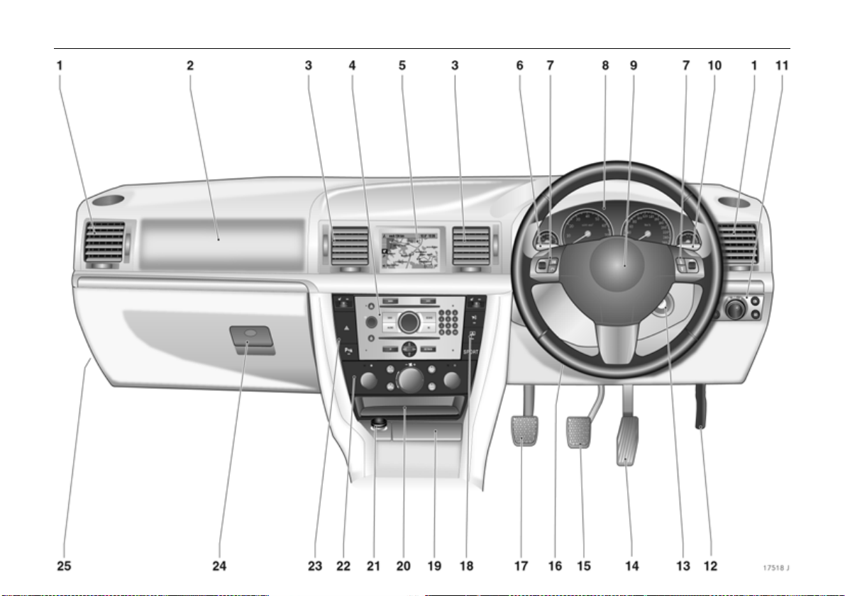
1 Side air v ents ........ .... ......... ......... .... 142
2 Front pa ssenger’s airbag . ......... ..... 81
3 Centre air v ents .... .... ......... ......... ... 142
4 Infotainm ent system 3 ..... .... ........ 137
5 Central information display for
time, date, outside temperature,
Infotainment system 3,
check control 3,
trip computer 3,
Electronic Climate Control 3 ......... 10 8
6 Turn signal lights... ......... .... ......... .... .... 7
Headlight flash,
dippe d be am a nd main be am ......... 7
Door-to-door lighting 3 .... ......... .... 133
Parking lights ... ..... ......... .... ......... ... 134
Cruise control 3 .... .... ......... .... ......... 200
7 Steering wheel remote control 3 .. 137
8 Ins trume nts ........... ......... .... ......... .... ..98
9 Horn .... ............. ......... ..... ........ ..... ...... 1 1
Drive r’ s airbag . ..... ......... ........ ......... . 8 1
Pa ge
10 Windscreen wiper,
windscreen wash system,
headlight wash system 3 and
rear window wash system 3 .... ..... .. 1 1
11 Pa rking lights, dipped beam ... ..... 128
Instrument illumination ........ ......... 1 3 4
Fog tail lig ht .... ......... ........ ......... ..... 131
Front fog lights 3 ..... ........ ......... ..... 130
Headlight range adjustment 3 ..... 13 1
12 Unlock ing the bo nnet ....... ......... .... 228
13 Starter switch with steering
colum n lock ......... ..... ........ ..... ......... ... 6
14 Ac celerator pedal .... ........ ..... ........ 184
15 Brake peda l ..... .... ......... ......... 185, 208
16 Steering wh ee l adjustm ent .. .... ........ 6
17 Clutch ped al 3 . ......... ........ ......... .... 1 85
18 Heated seat (right) 3 and
seat climate control 3 . .... ......... .....1 4 4
Vauxhall alarm system 3 ......... ..... . 38
Rear window blind 3 ... ......... ......... . 49
and
Electronic Stability Programme 3 196
SPORT mode
3 ........ ........ ..... ........ 198
Page
19 As htray s ......... ......... .... ......... ........... 94
20 S towa ge c om partment
with AUX input 3 .... ......... .... ......... 13 8
21 Cigarette lighter 3 or socket ... .... .. 93
22 Clim ate c ontrol .. ......... ......... ......... 163
23 Heated seat (left) 3 .... ..... ......... .... 144
Haz ard warning lights .... .... ......... 131
Parking distance sensors 3 . ......... 202
24 Glove compartment ... ......... ... 95, 135
25 Fusebox . ......... .... ......... .............. ..... 246
Page 15

10 In brief
Control indicators
O
I
R
p
v
W
8
1
T
(
j
Turn signal lights,
see pages 7, 98, 130.
Engine oil pressure,
see page 98.
Bra k e sy st em , clu t ch sy ste m,
see page s 99, 209, 276.
Alternat or,
see page 99.
Airb ag systems 3,
belt t ensioners 3,
see page s 74, 86.
Coola nt temperat ure,
see page s 100, 106.
Exterior l ights,
see page s 100, 128.
SPO RT mode of autom atic
tra nsm ission 3,
see page s 100, 178, 179.
Winter programme of
autom atic transmis sion 3 or
Easytronic 3,
see page s 100, 172, 180.
Door open 3,
see page 100.
Easytronic 3,
start ing the engine 3,
see page s 100, 169.
t
s
>
C
r
r
u
X
A
!
H Coolant level,
Bulb re pla c em ent 3,
see pages 100, 252.
Open lugg age comp artme nt,
see p ages 34, 101.
Front fog lights 3 ,
see pages 101, 130.
Main beam,
see pages 7, 101, 128.
Fog t ail li ght,
see pages 101, 131.
Pa rking distance sensors 3,
see pages 101, 202.
Continuous Damping Control 3 ,
SPORT m ode,
see pages 101, 198.
Seat belt 3,
see page 101.
Engine electronic s, transmission
ele ct ron ics 3, diesel fuel filter 3,
immob iliser,
see pages 27, 101, 192.
Preheating for diesel engines 3,
diesel p artic le fi lte r 3,
see pages 102, 194.
see pages 102, 275.
u
p
v
y
S E ngine o il level 3 ,
m
Y
Z
w
B
An ti -lock B r a ke Sy st em (A BS),
see page 210.
Electro-hydraulic power
assisted steering,
see page 103.
Electronic S tability Prog ramm e
Plus
(ESP®
see page s 103, 196.
Seat occupancy recogniti on 3,
see page s 87, 103.
see page s 103, 272.
Cruise control 3,
see page 200.
Fuel level,
see page s 103, 106, 228.
Exhaust gases 3,
see page s 104, 192.
Ty re pressure monitori ng
system 3,
see page s 104, 204.
Ad aptiv e Forward L ighting
(AFL) 3,
see page s 104, 132.
) 3,
Page 16
11In brief
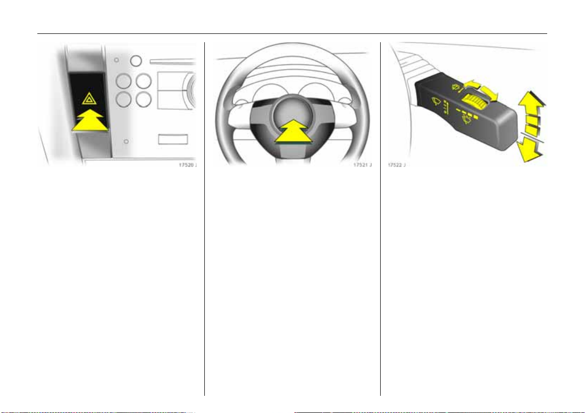
Hazard warning lights:
On = Press ¨
Off = Press ¨ again
6 Hazard w arning lights – see page 131.
Activate horn:
j in centre of steering
Press
wh eel
6 Airbag systems 3 – see pag e 81,
remote control on steering wheel 3 –
see page 137.
Windscreen wiper:
Gently push stalk upwards
§ =Off
$ = A djustable timed
interval wipe
% =Slow
& =Fast
Press the stalk down from position §:
Single swipe.
6 Windscreen wiper – see page 126,
adjustable wiper interval 3 – see page 126,
wiper blades – see pages 277, 278,
vehicle care – see page 264.
Page 17
12 In brief
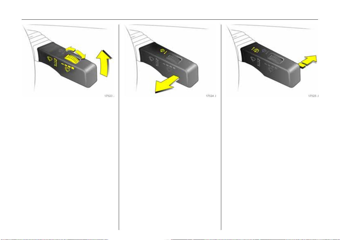
Automatic wiping with rain
sensor
3:
Gently push stalk upwards
§ =Off
$ = Automatic wipin g with
ra in se nso r
Automatic wiping $ :
Low sensitivity: Move adjuster wheel
to the left
High sensitivity: Move adjuster wheel
to the right
6 Windscreen wiper – see page 126,
wiper blades – see pages 277, 278,
vehic le care – see page 264.
Operating windscreen and
headlight wash systems
3 :
Pull stalk towards steering wheel
6 Windscreen wa sh system and headlight
wash system 3 – see page 127,
further information – see pages 264, 278.
Operating rear window wiper 3
and wash systems
3 :
Wiper on = Push stalk
forwards
Wiper off = Push stalk
forward s agai n
W as h = H ol d sta lk in f ully
forwards position
6 Rear window wiper 3 and rear window
wash 3 systems – see page 127,
further information – see page s 264, 277,
278.
Page 18
13In brief
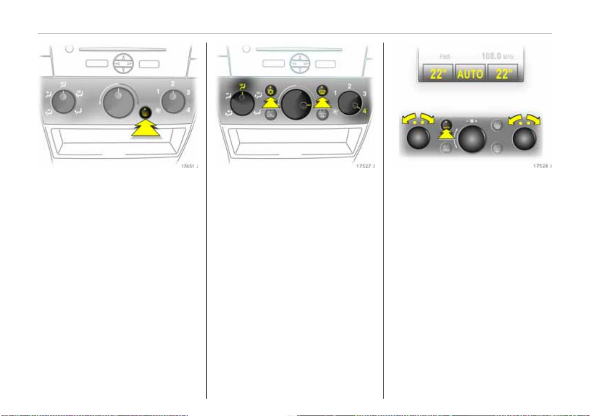
Heated rear window,
heated exterior mirrors:
On = Press Ü
Off = Press Ü ag ain
6 Air conditioning 3 – see page 140,
heated rear window, heated exterior
mirrors – see page 143.
To d emist or defrost windows:
Set a ir distribution to l,
turn rotary knob for temperature
and a irflo w clock wise;
Air conditioning system
3:
Press bu ttons n and V;
Automatic a ir conditioning
syste m
3:
Press buttons n and V,
turn rotary knob for
temperature clockwise,
airflow to A ;
Electronic Climate Control
3:
Press bu tton V
6 Climate control – se e page 140.
Setting automatic m ode of
Electronic Climate Control
3:
Press AUTO button,
s e t tem p era ture fo r d ri ve r’ s
and front passenger’s sides using
left and right rotary knobs
6 Electronic C limate Control 3 –
see page 156.
Page 19
14 In brief
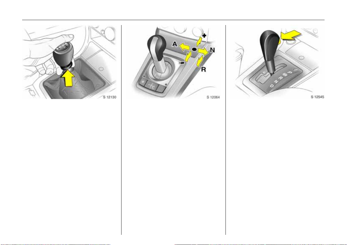
Manual transmission:
Reverse gear: with vehicle stationary, pull
the ring up three seconds after depressing
clutch pedal and engage gear.
If the gear does not engage, set the lever in
neutral, release the clutch pedal and
depress again; then repeat gear selection.
Easy tronic 3 :
N=Idling
o =Drive position
+ = Higher gear
- = Lower gear
A/M = Switch between
Automatic and Manual
mode
R=Reverse gear (with
se lector le v e r l ock)
The selecto r lever mus t alway s be mo ved in
the appropriate direction as far as it will
go. Upon release, it automatically returns
to the centre position. Pay heed to the
gear/mode ind icator in the transmission
display.
The footbrake must be depressed when
sta rting.
6 Easytron ic 3 – see page 168.
Automatic transmission 3 :
P=Park position
R = Reverse gear
N = Neutral position (idling)
D = Automatic gear selection
Selector lever in D to the left:
Manual mode
+=Higher gear
-=Lower gear
P or N must be engaged when starting.
Page 20
15In brief
In order to leave P, switch on ignition,
depress footbrake and press button on
selector lever.
To en gag e P or R, press button on selector
lever.
P Only with vehicle stationary, apply
ha nd brake bef oreh an d.
R Only if vehicle is stationary.
6 Automatic transmission 3 –
see page 176.
Before sta rti ng -o ff , check :
z Tyre pressure and condition –
see page s 204, 211, 299.
z Engine oil level and fluid levels in engine
compartment – see pages 271 to 279.
z All windows, mirrors, exterior lighting
and number plates are free from dirt,
snow and ice and are operational.
z No objects are placed in front of the rear
window, on the instrument panel or in
the area in w hich the airbags inflate.
z Seats, seat belts and mirrors are
correctly adjusted.
z Brake operation.
To start engine:
O p er a t e c l u t ch a nd b r ak e pe d a l s,
automatic transmission
3
in P or N,
Easytronic
3: Depress brake,
do no t accelerate,
Petrol engines: Turn key to 3;
Di es el eng ines : Turn ke y to 2 ,
when control indicator
goes out
1)
, tu rn ke y t o 3;
!
release key once engine
is running
To restart or switch off the engine, turn key
back to 0 .
To switch on the ignition, only turn the key
to 2.
6 Electronic im mobiliser – see pag e 27,
diesel fuel system – see page 228.
1)
Preh eating system switches on only if outside
temperature is low.
Page 21
16 In brief
Releasing th e handbrake:
Raise lever slightly,
press release button,
lower lever fully
6 Handbrake – see pag e 209.
Parking the vehic le
z Always ap ply the handbrake firmly
without pressing the release button;
to do this, fold up the armrest 3. Apply
handbrake as fully as possible on an
uphill or downhill incline. To reduce the
amount of force required to activate the
handbrake, depress the footbrake at the
same time.
z Sw itch off the engine; to do this, turn the
ignition key to 0. Remove the ignition key
an d tu rn the s tee ring whee l un til the
s tee r in g c o lu m n loc k ( a n t i- t h e ft
protection) engages. In vehicles with
automatic transmission 3, the ke y ca n
only be removed when the selector lever
is in P.
z If the vehicle is parked on a flat surface
or an uphill incline, engage first gear
before switching off the ignition if you
have manual transmission or
Easytronic 3 ; if the vehicle has
automatic transmission 3, place the
selector lever in P. On an uphill incline,
also turn the front wheels away from the
kerb.
If the vehicle is on a downhill incline,
eng age rever se ge ar be fore switch ing of f
the ig nition if you have ma nual
transmission or Easytronic 3; if the
vehicle has automatic transmission 3,
place the s elector leve r in P. A lso turn the
front wheels towards the kerb.
z Lock the doors and luggage
compartment and activate the Vauxhall
alarm system 3 by pressing button p on
the remote control.
To activate the mechanical anti-theft
locking system 3 , press button p again
no more than 15 seconds after locking.
Advice when parking:
z Do not park vehicle on easily ignitable
surfaces, since the hot exhaust system
tempe ratures could cau s e the s urface t o
ignite.
z On vehicles with Easytronic 3, control
indicator R flashes for a few seconds
after the ignition is switched off if the
ha nd brake ha s n o t be en a pplied –
see page 174.
z Close windows and sunroof 3 .
z The engine cooling fans may run after
the engine has been switched off –
see page 271.
6 Remote control – see page 28,
central locking – see page 30,
Vauxhall alarm system 3 – see page 38,
vehicle decommissioning – see page 281.
Page 22

That was a brief overview of the
mos t im p o r tant in fo r ma tio n for
your first drive in your vehicle.
The other page s of this chapter
contain a summary of the
interesting functions in your
vehicle.
The rem a in ing ch apte r s o f t h e
Owner’s Manua l contain
important information on
operation, safety and
maintenance as well as a
com plete in dex.
17In brief
Page 23
18 In brief
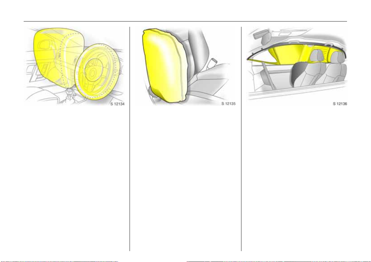
Airbag system
The airbag system consists of several
separate systems.
Front airb ag system
The front airbag system will be triggered in
the event of a serious accident involving a
frontal impact and forms safety cushions
for the driver and front passenger.
The forward movem ent of the d river and
front passenger is checked a nd the risk of
injuries to the upper body a nd head are
thereby substantially reduced.
Side airb ag system 3
The side a irbag system triggers when a
side-on collision occurs and provides a
safety barrier for the driver and/or front
passenger in the respective front door
area. This reduces the risk of injury to the
upper body conside rably, in the event of a
side-impact.
Curtain ai rbag system 3
The curtain airba g system triggers in the
event of a side-on collision and provides a
safety barrier in the h ead area on the
respe cti ve side of t h e veh icle. This red uce s
the risk of injury to the head considerably in
the event of a side-on collision.
6 Airbag systems 3 – see page 81.
Page 24
19In brief
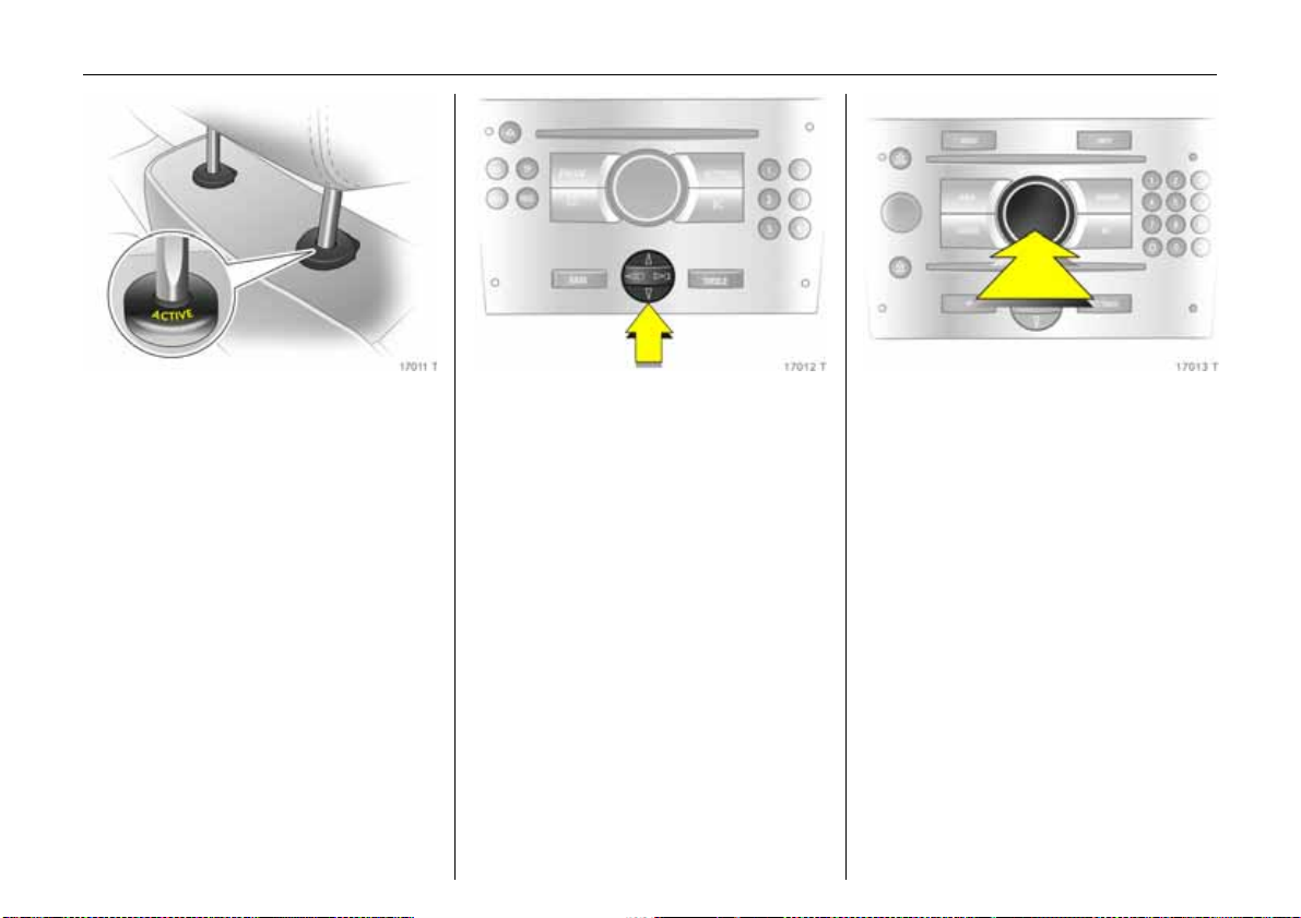
Active head restraints 3 at front
seats
In the event of a rear-im pact, the active
head restraints tilt forwards a little. The
head is more effectively supported by the
head restraint and the danger of injuries
caused by whiplash in the neck area is
reduced.
Active head restraints are identified by the
lettering ACTIVE on the head restraint
guide sleeves.
6 Head restraints – see page 55.
Operating menus in th e
information display
Menu options are selected using menus
and using the buttons/four-way button
or the multi-function knob of the
In fotainme nt sy ste m 3 or th e lef t-h a n d
adjuster wheel 3 on the steering wheel.
The respective menu options are shown
on t h e dis play.
To select with four-way button:
Press the four-way button up, down, right
or lef t.
3
Selection using multi-function knob:
Rotate and press multi-function knob.
To exit a m enu, turn the multi-function
knob left or right to Return or Main and
select.
Page 25
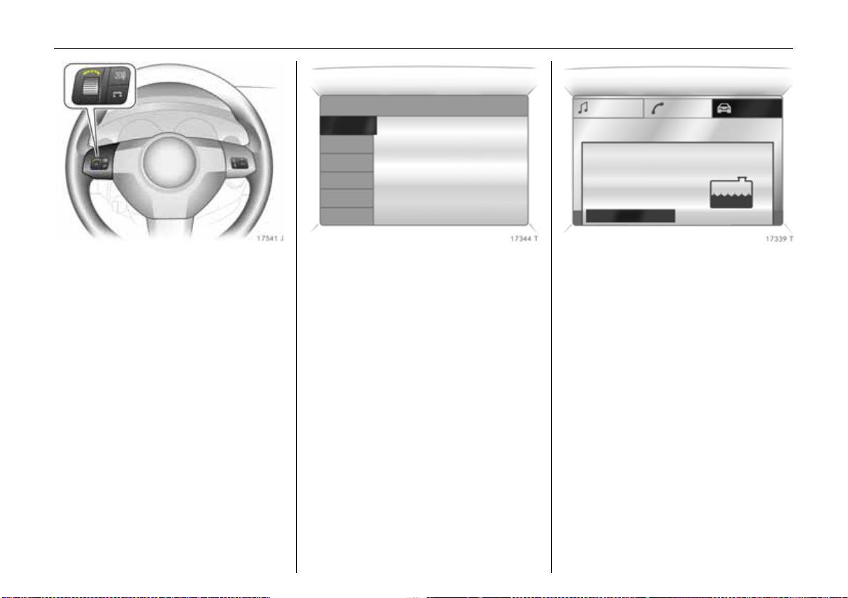
20 In brief
Ü Board Computer 19,5° 19:36
BC 1 All values
BC 2
Timer
Tyres
1111
257.0 miles
Ø40mph
7.0 ga l .
8888
Ø 31 .0 miles/gal.
Coolant level
check
OK
Selection using left-hand adjuster wheel on
steering wheel:
Rotate and press adjuster wheel.
6 Information display – see page 108.
Trip computer 3
The trip computer provides information on
driving data, which is continually recorded
and evaluated electronically.
Functions:
z Range,
z Instanta neous consumption,
z Distance travelled,
z Average speed,
z Effective consumption,
z Average consumption,
z Stop watch,
z Tyre pressure 3.
6 Trip computer 3 – see pages 114, 120.
Check control 3
The check control software monitors:
z Flu id le vels ,
z Tyre pressures 3 ,
z Remote control battery,
z Vauxhall alarm system 3,
z Important exterior lights, including
cables and fuses.
6 Check control 3 – see page 124.
Page 26
21In brief
Remote control on steering
wheel
The functions of the Infotainm ent system 3
and the information display can be
operated with the buttons and ad juster
wh ee ls on the steering whe el.
Further information is available in the
Infotainment system operating
instructions.
6 Remote control on steering wheel 3 –
see page 137,
Infotainment system – see page 137.
3
Twin Audio 3
Twin Audio p rov ides rear seat occupants
with the opportunity to listen to a different
audio source than the one selected by the
driver on the Infotainment system 3 .
Only a n audio source that is not currently
active on the Infotainment system can be
controlled using Twin Audio.
Two headphone connections are a vailable,
with separate volume c ontrols.
Further information is available in the
In fotainme nt sy ste m ope ra tin g
instructions.
6 Twin Audio 3 – see page 138.
FlexOrganizer 3
The side walls contain retaining strips,
where various components can be
attached to divide the luggage
compa rtm en t or fas ten loads.
The sy ste m consis t s o f:
z Variable partition net,
z Variable partition wall,
z Partition rod,
z Mesh pockets for the side walls,
z Hooks.
6 Fle xOrg aniz er 3 – see page 69.
Page 27
22 In brief
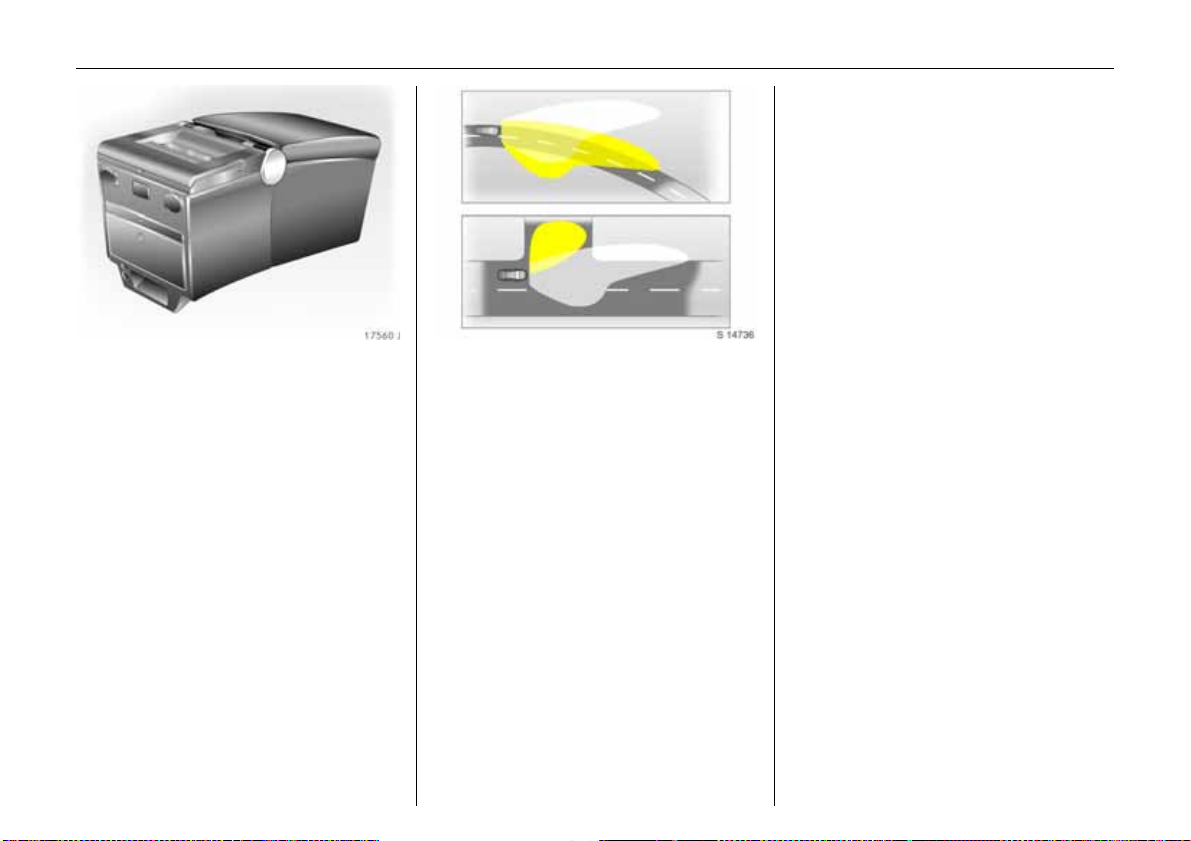
Travel Assistant 3
The Trav el Assistant contains:
z Arm re st,
z Stowage compartments,
z Was te co ntaine r,
z Drink holders,
z Acc es sor y socke ts,
z Connection console
e.g. for DVD player 3,
z Elec tric cool box,
z Foldaway tables,
z Tw in Audio (rear audio module) 3 or
stowage compartm ent.
The Trav el Assistant is installed on a
console above the centre seat in the rear.
6 Travel Assistant 3 – see page 58.
Adaptive Forward Lighting
3
(AFL)
On vehicles with Bi-Xenon headlights, AFL
improves illumination of:
z C urves (curve lighting),
z Intersections and tight turns (turn
lighting).
C urve ligh ti ng
The Xenon light beam pivots based on
stee ring wheel po sition an d ve hicle spe ed,
from approx. 6 mph (10 km/h).
The headlights shine at an angle of up
to 15° to the right or left of the direction of
travel.
Turn lig hting
An add itional light illuminates at ce rtain
steering wheel settings (after approx. 90°),
turn signal settings and speeds up to
approx. 25 mph (40 km/h).
The light beam projects at a 90° angle to
the left or right of the vehicle up to a
distance of a pprox. 30 me tres.
Mot or way lighti ng
At higher speeds and continuous straight
ahead travel, the dipped beam
automatically raises slightly, thereby
increasing headlight range.
6 Adaptive Forward Lighting (AFL) 3 –
see page 132.
Page 28
Ü Board Computer
BC 1
BC 2
Timer
Tyres
23In brief
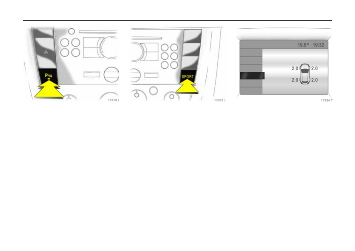
Parking distance sensors 3
When reverse gear is selected, the parking
distance sensors switch on automatically.
The parking distance sensors can also be
activated at speeds of less than 15 mph
(25 km/h) by pressing the r button on
the instrument panel.
If the vehicle approaches an obstacle to
the front or rea r, a series of signals is
audible in the vehicle interior. The interval
be twee n t he s ign als become s sh orter a s
the distance is reduce d. If the dista nce is
less than 30 cm , the signal will be
continuous.
6 Parking distance sensors 3 –
see page 202.
SPORT mode 3
To activate
Pre ss th e SPORT button. The LED in the
button illuminates.
SPORT mode is used to change
damping 3 , s tee ri ng 3, throttle application
and the shifting times and shifting points
for E as ytr o nic 3 and automatic
tra nsmission 3 whilst driving.
Damping and steering 3 become more
direct and provide better contac t with the
road surface. The engine reacts more
quickly to accelerator movements.
With automatic transmission 3, the shift
tim es are reduced and gear changes occur
at higher engine speeds (not when cruise
control 3 is a ctive).
6 SPORT mode 3 – see page 198.
Tyre pressure monitoring
system
The tyre pressure monitoring system
continuously monitors the pressure of all
four tyres while the vehicle is being driven.
A pressure sensor is insta lled in ea ch wheel.
The tyre pressures of the individual tyres
are transmitted to a controller, where they
are compared.
The current tyre pressures ca n be
displayed on the Graphical Information
Display or the Colour Information
Display 3.
Deviating tyre pressures are displayed in
the form of messages on the information
display whilst driving.
6 Tyre pressure monitoring system 3 –
see page 204.
3
Page 29
24 In brief
Electrically operated tailgate,
Estate
z To op en:
– Hold down remote control button r
- or -
– When the key is inserted in the starter
- or – Unlock the tailgate and open by pulling
3
(see page 35, Fig. 17548 J) for a pprox.
1second.
switch and the handbrak e is app lied,
hold down the x button in the driver’s
door for approx. 1 second.
the catch beneath the handle.
z To close:
–Hold down the r button on the remote
control until the tailgate is closed.
- or – When the key is inserted in the starter
switch and the handbrake is applied,
hold down th e x button in the driver’s
door until the tailg ate is shut.
- or -
–Press the F button in the tailgate.
6 Electrically operated tailgate 3 –
see page 35.
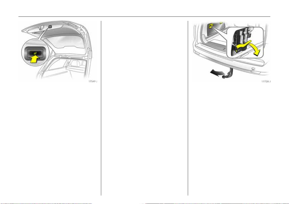
Towing equipment with pivoting
coupling ball bar
The release lever is in the left stowage
compa rtment in the lugga ge
compa rtm ent. Open cover.
z Pull release lever downwards.
– The LED on the lever is illuminated while
the coupling b all bar is not engaged.
– In addition, a warning buzzer sounds
and the coupling ball bar pivots
downwards.
z Pivot the coupling ball bar backw ards
until it e ngages.
– LED must extinguish,
– Warning buzzer must cease,
– Otherwise, repeat the procedure.
6 Towing equipment with pivoting
coupling ball b ar 3 – see page 222.
3
Page 30
Diesel particle filter 3
Th e dies el pa rticle filter s ystem remo ves
polluting soot particles out of the engine
exhaust gases. The system includes a
self-cleaning function that operates
automatically whilst driving. The filter is
cleaned by burning the trapped soot
particles at a high temperature. There may
be an increase in fuel consumption,
exhaust smell, and engine cooling fan
opera tion 3 during the self-cleaning
opera tion.
The self-cleaning function cannot operate
automatically during certain driving
situations where the engine does not reach
its normal operating temperature.
An example of this would b e driv ing only
short distances in cold weather.
25In brief
If th e f ilter ne eds cle aning and rec ent
driving situa tion s did not allow the function
to autom atically operate, then control
indicator ! will flash. If this occurs, then
you may continue to drive the vehicle
normally . The vehicle will not be damage d
and does not require service.
The self-cleaning function will
automatic ally operate whilst driving after
the engine has reached its normal
operating temperature. Control
indicator ! will continue to flash until the
self-cleaning operation is complete. This
may ta ke up to 20 minutes of driving.
The time will be shorter at higher vehicle
spe eds.
6 Dies el particle filter 3 – see page 194.
Page 31

26 Keys, doors, windows, sunroof
Keys, doors, windows,
sunroof
Re placem ent keys ... ..... ......... ........ ...... 26
Lock cylinde rs ...... ......... ......... ........ ...... 26
Ca r Pass 3... ......... .... ......... ............. ...... 26
Key with foldaw ay key section 3 ...... . 26
Electronic immobiliser....... ......... .... ...... 27
Store and activate personal vehicle
settings using the remote control .... 28
Re mote control .... .... ......... ......... ......... . 2 8
Central locking system ..... ..... ........ ...... 3 0
Fault when locking or u n locking........ . 33
Luggage compartment.... ......... .... ...... 34
Vauxhall alarm system 3. ............. ...... 38
Child safety locks ..... ......... ......... ......... . 41
Universal remote control in mirror
hou sing 3.. ......... .... ......... ..... ........ ...... 41
Exterior mirrors......... ......... ......... ......... . 43
Interior mirror ....... ......... ......... ........ ...... 44
Ele ctric windo ws 3 ........ ......... .... ......... . 4 5
Wind ow s in re ar doors . ......... ........ ...... 47
Sunroof 3 .... .... ......... ..... ......... .... ......... . 4 7
Electrically operated rear window
blind 3 .. .... ......... .... ......... ..... ........ ..... . 49
Sunblinds for rear door windows 3 ... . 49
Replacement keys
The key number is specified in the vehicle
documents and in the Car Pass 3.
The key is a constituent of the electronic
immobiliser. Ordering keys fr om a Vau xhall
Authorised Repairer g uarantees problemfree operation of the electronic
immobiliser.
Keep the spare key in a safe place.
Locks - see page 266.
Lock cylinders
Des igned to free-wh e el if they are
forcefully rotated without the correct k ey or
if the correct key is not fully inserted.
To reset, turn cylinder with the correct key
until its slot is vertical, remove key and then
re -insert it. If the cylinder still free-wheels,
turn the key through 180° and repeat
op er at io n .
Car Pass 3
The Car Pass contains all of the vehicle’s
data and s h o uld th erefore not be kept in
the vehicle.
Have your Car Pass to hand when
co nsulting a V aux ha l l Au th or i s ed Re pairer .
Key with foldaway key section 3
Press button to extend. Press button to
retract and audibly engage key section.
Page 32

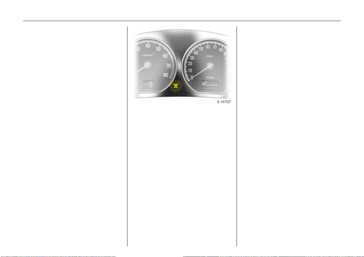
27Keys, doors, windows, sunroof
If control indicator A illuminates a fter
the engine is started, there is a fault in
th e engine elec tronics or transmiss ion
electronics 3 (see pages 101, 174, 182,
192) or there is water in the diesel fuel
filter 3 (see page 274).
Not e
The immobiliser does not lock the doors.
Therefore, after leaving the vehicle always
lock it and switch on the Vauxhall alarm
system 3 – see pages 30, 38.
Electronic immobiliser
The system checks whether the vehicle m ay
be sta rted using the key that has been
in se rted. If the k ey is recogn ised as
"authorised" the vehicle can be started.
The check is carried out via a transponder
in the key.
The electronic immobiliser activates
automatically when the key is removed
from the starter switch.
Th e code numbe r of the e lectr on ic
immobiliser is given in the Car Pass.
Control i nd icator for imm obilise r
Control indica tor A illuminates briefly
wh en the ig nitio n is sw itched on.
If the control indicator flashes when the
ignition is on, there is a fault in the system;
the engine cannot be started. Switch off
the ignition and then repeat the start
attempt.
If the control indicator A continues to
flash, try to start the engine using the spare
key and contact a workshop for assistance.
Page 33

28 Keys, doors, windows, sunroof
Store and activate personal
vehicle settings using th e remote
control
The last settings selected for:
z Instrument illumination,
z Central locking,
z Memory function 3 for driver’s seat
and mirror,
z Elec tronic Climate Control 3
are automatically stored depending on the
vehicle key used .
Different settings are stored for each
remote control. Use of a remote control will
activate the settings associate d with it.
The settings for five remote controls can be
stored.
Remote co ntrol
The remote control is inte grated in the key.
Used to operate:
z C entral locking system,
z Me chanical anti-theft locking system 3 ,
z Vauxhall alarm system 3,
z Electrically operated tailgate, Estate 3.
In a ddition, electric windows 3 and electric
sunroof 3 can be closed using the remote
control.
The remote control has a range of approx.
5 me tres . This rang e ca n be a ffe cted by
outside influences. Aim the remote control
at the vehicle to operate.
Handle the remote control with care,
protect it from moisture and high
temperatures and avoid unnecessary
operation.
The hazard warning lights illuminate to
indicate that the remote control is
operational.
C entra l locking s ystem,
see page 30.
Mechanic al anti -theft locki ng s ystem 3 ,
see page 30.
Boot lid or ta ilgate,
see page 34.
Vauxhall alarm system 3,
see page 38.
Electric windows 3 ,
see page 45.
Electrica lly op era te d sunr oof 3,
see page 47.
Page 34

29Keys, doors, windows, sunroof
Fault
If the central locking system cannot be
operated with the remote control, it may b e
due to the following:
z The range of the remote control has
been exceeded.
z Remote control battery voltage is too
low. Battery replacement - see next
column.
z Frequent, repeated operation of the
remote control outside the reception
ra nge of the vehicle (e.g. too far from
vehicle, remote control is then no longer
re cognised). Remote control
synchronisation – see end column.
z If the central locking system is
overloaded as a result of repeated
operation at short intervals. The power
supply is cut off for a brief period.
z Inte rference fro m higher-power radio
waves from other sources.
To eliminate the cause of a fault, we
recommend contacting a workshop for
assistance.
Manual unlocking and locking using the
vehic le key - see page 33.
Make sure that you dispose of old batteries
in accordance with environme ntal
protection regulations.
Remote control synchronisation
After a battery change, unlock door with
key in lock - see page 33. Inserting the key
into the lock synchronises the remote
control.
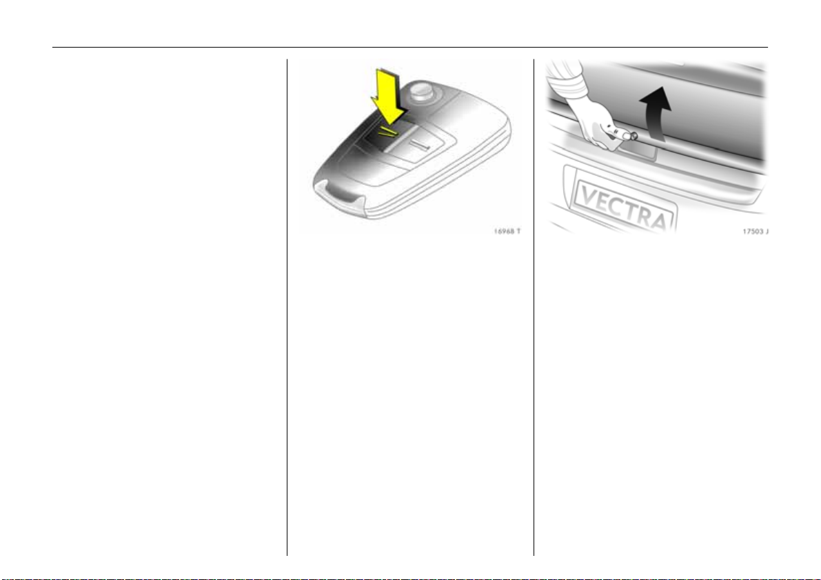
Remote control b attery rep lacement
Replace the battery as soon as the range
of the remote control becomes reduced.
Extending the key – see page 26.
Open the remote control. Replace the
battery (b attery type – see page 307),
noting insta llation position. Close the
re mo t e c o nt ro l .
Page 35

30 Keys, doors, windows, sunroof
Central locking system
For doors, boot lid/tailgate and tank flap.
To unlock
Press button q on remote control.
To lo ck
Press button p on remote control.
Mechanic al anti -theft locki ng s ystem 3
9 Warnin g
Do not use the system if there are people
in the vehicle. The doors cannot b e
unlocked from inside.
All doors must be closed . Press button p
on remote control again no more than
15 se co n ds afte r locking.
Lock buttons on all doors are positioned
such that doors cannot be opened.
If the ignition was on, the driver’s door
must be opened and closed once so that
the vehicle can be secured.
Page 36

31Keys, doors, windows, sunroof
Program ming unlocking mode 3
When th e vehicle is delive red from the
fact ory, the remo te control is pres et so th at
a single press of the q button opens all of
the doors and the luggage compartment.
The unit can be configured so that a single
press of the q button unlocks the entire
vehicle or just the driver’s door.
Change to presetting:
Hold button q on the remote control and
button m in the driver’s door depressed
simultaneously until a double buzzer
sounds. Afterwards, only the driver’s door
will be unlocked when button q is pressed
once.
Th e entire ve hicle is then unlo cke d by
pressing button q on the remote control
twice.
To restore the original settings, hold
button q on the remote control and
button m in the driver’s door depressed
simulta neously until a buzzer sounds.
The current setting is stored for the remote
control - see page 28.
Cen tral l oc king sw itch for loc king a nd
unl ocking the doors from inside the
vehicle
Press button m in the driver’s door:
Doors and luggag e comp artment are
locked.
Press button ) in the driver’s door:
Doors and luggag e comp artment are
un lo cke d.
In the Estate with electrically operated
tailg ate 3, the doors and luggage
compartment are locked and unlocked
with button m.
When the mechanical anti-theft locking
sy st e m is act ive 3 (see page 30), the doors
cannot b e unlocked with this button.
If the vehicle is locked using the remote
control, buttons m and ) in the driv er’s
door are inoperable.
Autom atic locking 3
The central locking can be set to lock
automatically at a certain speed.
To activate the function, hold button p on
the remote control and button m in the
driver’s door depressed simultaneously
until a double buzzer sounds.
The doors and luggage compartment a re
unlocked by switching off the ignition or by
pressing button ) or, for Estate with
electrically operated tailgate 3, b y
pressing button m in the driver’s door.
Individual doors can b e unlocked by
pulling the lock button.
To deactivate the function, hold button p
on the remote control and button m in the
driver’s door depressed simultaneously
until a buzzer sounds.
The current setting is stored for the remote
control - see page 28.
Page 37

32 Keys, doors, windows, sunroof
Note
z If the driv er’s door is not closed properly,
the central locking system will unlock
again immediately after locking.
z 30 seconds after unlocking using the
remote control, the doors automatic ally
lock again 3 if neither a door nor the
lugga ge compartment has been
opened.
z To lock the doors from within (e.g. to
prevent undesired acc ess from outside),
press the ce ntral lock ing button m.
z If they are locked, the doors and the
lugga ge compartment unlock
automatically in the event of an accident
of a certain severity (to permit outside
ass istan ce ) . Prere quisite: Ign ition mu st
not be switched off.
Closing the windows 3 and sunroof 3
from outside u sing th e remote contr ol
9 Warning
Take care when ope rating the e lectric
windows 3 and the sunroof 3. Risk of
injury, particularly to c hildren.
Vehicle passe ng ers must be informed
accordingly.
Keep a close watch on the windows and
sunroof when closing them. Ensure that
nothing becomes trapped in them a s
they move.
Th e electric windows 3 can be closed from
outside: hold down button p on the
remote control until all windows are closed.
The sunroof 3 can be closed from outside:
hold down button p on the remote control
until the roof is fully closed.
Vehicle with electrically re trac ta ble
exterior mirrors 3:
When clos ing th e win dows usin g the
remote control, the exte rior mirrors will also
be retracted. The mirrors will be folded
back out when the vehicle is unlocked using
the remote control.
If the mirrors are retracted using the button
in the driver’s door, they remain in this
position when the doors are unlocked.
Page 38

33Keys, doors, windows, sunroof
Automatic closing 3
If the mechanical anti-theft locking
system 3 is activated, the electric
windows 3 and sunroof 3 are
automatically closed and the electric ally
retractable exterior mirrors 3 are
automatically retracted as soon as the rain
sensor 3 detects water on the windscreen.
To safeguard the battery from discharge
by the rain sensor 3, after four hours the
electric windows 3 and sunroof 3 are
automatically closed and the electric ally
retractable exterior mirrors 3 are
automatically retracted.
For further information on electric
windows 3 and the sunroof 3 –
see page s 47, 49.
Fault
If the central locking system cannot be
operated with the remote control, it may b e
due to the following:
z The central lock ing system is overloaded
as a result of repeated operation at short
intervals. The power supply is cut off for
a brief period.
z Defective fuse in fusebox –
seepage246.
Seek the assistance of a workshop to rectify
the cause of the fault. To open the driver’s
door with the key - see the following
section.
Fault when locking or unlocking
Remote control fa ul t
To un lock:
Insert key into lock in driver’s door and turn
tow ards front of vehicle as far as it will go.
Turn ke y back to v ertical position a nd
re move from lo ck. Unloc k driver’s d oor with
central locking switch - see page 31.
The mech anical anti-th eft lock in g sy ste m 3
is deactivated when the key is inserted in
the starter switch.
To loc k :
Open front p assenger’s door, close driver’s
door, lock vehicle using central locking
switch (see page 31), close front
passe nge r’s door.
Ma lfunction in centra l locki ng system
To unlock:
Insert key into driver’s door lock and turn
towards front of vehicle a s far as it will go.
Turn key back to a vertical position and
remove. The other doors can be unlocked
by pulling the interior lock button (unless
the mechanical anti-theft locking system 3
has been e nabled). The luggage
compartment and the tank flap
remain locked.
To lock:
Lock front pa ssenger’s door and rear doors
by pressing the interior lock button. Lock
driver’s door with key in lock. Turn key
towards rear of vehicle as far as it will go,
turn key to a vertical position and remove.
The unlocked tank flap and the lugga ge
compa rtment cannot be locked.
Page 39

34 Keys, doors, windows, sunroof
Lugg ag e comp artment
To unlock
Press button q on remote control.
To op en
The luggage compartment of the Saloon /
Hatch is opened by pressing the button,
and the luggage com partment of the
Estate is opened by pulling the catch
beneath the handle.
Illumination of control indicator s
indicates that the boot lid/tailgate is open.
For notes on open boot lid/tailgate -
see page 37.
Elec trically operated tailgate, Estate 3 –
see next page.
To close
There is a handle on the inside of the
boot lid/tailgate for closing the luggag e
compa rtm ent.
With the Estate, do not operate the catch
beneath the handle when closing,
otherwise the luggage compartment will
be unlocked again.
Page 40

Electrically operated tailgate, Estate 3
In Estate vehicles with an elec trically
operate d tailgate, the tailga te can b e
ele ctrica lly open ed an d c lo s ed after
unlocking.
9 Warning
Make sure there is more than 2 metres
clearance before operating the electric
tailgate. Observe the pivoting z one of the
tailgate during operation and d o not
enter the piv oting zone.
35Keys, doors, windows, sunroof
To lock
Press button p on the remote control
– or –
Press central locking button m in d riv er’s
door when the doors are closed.
To op en :
Unlock the vehicle by pressing button q on
the remote control; the tailgate is opened
electrically by pulling the catch beneath
the handle.
– or –
Briefly press button r on the remote
control to unlock the tailgate (the doors
remain locked.) The tailgate is opened
electrically by pulling the catch beneath
the ha ndle .
– or –
Hold down button r on the rem ote control
for more tha n 1 second (the doors remain
locked); the tailgate is unlocked and opens
electrically
– or –
6
Page 41

36 Keys, doors, windows, sunroof
With the key in the starter switch and the
handbrake applied, hold button x in
the driver’s door depressed for approx.
1 secon d; the tailgate o pens ele ctrically.
To clos e :
Hold d ow n button r on the remote control
until the tailgate is closed.
– or –
Hold down button x in the driver’s door
wh en the k ey is inserte d in the starter
switch until the tailgate is closed.
– or –
Press button F in the tailgate; the tailgate
closes electrically.
To lock, press button p on the remote
control.
Tailgate opening and closing is indicated
by the rear turn signal lights flashing three
times.
If the luggage compartment is not closed
within 20 minutes of opening, the button in
the tailgate is deactivated.
Page 42

37Keys, doors, windows, sunroof
Interruption of tailgate opening/closing
procedure
The opening or closing process is
immediately interrupted by:
briefly pressing button x in the driver’s
door,
– or –
button r on the re mote control,
– or –
the external button beneath the handle,
– or –
button F in the tailg ate.
The tailgate remains in this position for
10 se co nd s a nd the n slowly reope n s.
Safety function
The tailgate has an obstruction detection
fa cility . If the tailgate encounters
resistance during the automatic closing
movement, the closing procedure is
stopped imm ediate ly and the tailgate is
slowly op ened again.
Vehicles with towing equipment 3:
When towing a caravan/trailer, the
tailg ate cannot be opera ted using
button r on the remote control or
button x in the driver’s door.
Fault in electrically operated tailgate
If the electronic drive should fail, the
tailg ate c an be op en ed and closed
manually, although more force is required
to close the tailgate.
Opening the tailgate when the doors are
locked via the central locking system
If th e doors are locked via th e central
lock ing syst em, the tailgate can be op ened
by pressing button r o n the rem ote control
and pulling the catch be neath the handle.
Open boot lid, open tailgate
9 Warnin g
Do not drive with the boot lid or tailgate
open or ajar, e.g . when tran s porting
bulky objects, since toxic exhaust gas
could penetra te the interior.
Also, the number plate of the Estate
cannot be clearly read unless the
luggage compartment is closed.
Fitting accessories to the boot lid/tailgate
will increase its weight. If it becomes too
heavy, the boot lid/tailgate will then not
stay open.
Page 43

38 Keys, doors, windows, sunroof
Vauxhall alarm system 3
Monitors:
z Doors, luggage compa rtm ent, bonnet,
z Passenger compartment,
z Vehicle tilt, e.g. if it is raised,
z Ignition.
To activate
All doors, windows, the sunroof 3 and the
bonnet must be closed. Press button p on
the remote control.
If the ignition was switched on, the driver’s
door must be opened and closed again so
that the anti-theft alarm system can be
activated again.
Act ivat ion with out monitoring of
passenger compartment and vehicle tilt
Activate e.g. when animals are le ft in the
vehicle.
1. Close boot lid/tailgate and bonnet.
2. Press button Ä; LED in button flashes
(maximum of 10 seconds).
3. Close doors.
4. Switch on anti-theft alarm system.
LED illuminates. After a pprox.
10 seconds, the system is activated
without monitoring of the passenger
compartment or vehicle tilt. LED
flashes until system is switched off.
Page 44

After the first 10 seconds of anti-theft
alarm system activation:
z LED flashes
slowly
z L ED illuminates
for approx.
1second
If a system fault occurs, contact a
wo rk shop for as sis tan ce.
=System switched on.
= Switch-off function.
39Keys, doors, windows, sunroof
Light e mit ting d iode (LED)
During the first 10 seconds of anti-theft
alarm syste m activation:
z LED
il l u mi n a t e s
z LED flashe s
quickly
= Test, switch-on delay.
= Door, luggage
compartment or
bonnet op en, or
system fault.
To deactivate
Press button q on the remote control
– or –
turn on the ignition.
If there is a fault in the remote control,
unlock vehicle as described on page 33.
If the alarm is triggered when the driver’s
door is opened, deactivate the anti-theft
al arm sy ste m by switc hin g o n the ign ition .
Page 45

40 Keys, doors, windows, sunroof
Est ate with electrically operated
tailgate 3 :
To open and close the luggage
compartment when the anti-theft
alarm system is active:
1. Briefly press button r on the remote
control – luggage compartment is
unlocked (see page 34), and monitoring
of the passenger c ompartment and
vehicle tilt is disabled.
2. Open lug gage compartment –
seepage34.
3. After the luggage compartment is
closed, monitoring o f the pas seng er
compa rtment, luggage comp artm ent
and vehicle tilt is reactivated after a
5 minute delay and the tailgate is
locked. To override the delay, press
button p on the remote control.
Note
z C hanges to the vehicle interior, such as
th e u se of ex tr a seat cove rs , could imp air
th e function of passeng er comp artment
monitoring.
z Disable passenger compartment
monitoring if the vehicle interior is being
heated.
Alarm
An alarm can be triggered whilst the antitheft alarm system is active, indicated by:
z an acoustic signal (horn) and
z a v isual signal (hazard w arning lights).
The number of alarms and the duration
thereof are stipulated by law.
The alarm can be silenced by pressing a
button on the remote control or by
switching on the ignition. The anti-theft
alarm system is deactivated at the same
tim e.
Ala rm siren wit h integrated b attery 3
The alarm siren monitors the on-board
voltage network and triggers an ala rm if
this network is manipulated (e.g. if the
vehicle’s battery is disconnected by
unauthorised persons). The alarm siren has
its own power supply and is therefore not
dependent on the vehicle’s battery.
If the vehicle’s battery is to be
disconnected (e.g. for maintenance work),
the alarm siren must be deactivated as
follows: switch the ignition on then off,
disconnect the vehicle’s battery within
15 se co nd s.
To switch off alarm siren:
Switc h ignition on then off.
Page 46

C h il d s af e ty lo cks
9 Wa rning
Use the child saf e ty locks wh en ever
children are occupying the rear seats.
Disregard may lead to injuries or
endanger life. Vehicle passengers must
be informed accordingly.
Turn rotary knob near rear door lock from
the vertical position using key;
door cannot be opened from inside.
Universal remote control in mirror
housing 3
To operate up to 3 different remotelyoperated systems (e.g. garage door,
domestic alarm sy stem, dom estic exterior
lig hting).
41Keys, doors, windows, sunroof
The programmed universal remote control
can replace the individual remote control
units of t h e sy ste ms t o be ope r ated . T hree
buttons on the underside of the mirror
housing can be used to operate various
systems.
Consult your Vauxhall Authorised Repairer
for details on compatible systems.
9 Warnin g
Ensure that no persons, animals or
objects are in the movement zone of the
system to be operated (e.g. a garage
door). Veh icle pa ssengers m ust be
informed of the hazards.
Basic programming of the univ ersal
remote cont rol system
1. Switch on ignition.
2. When programming for the first time,
press both outer buttons on the mirror
housing, until the control ind icator
alongside the buttons flashes rapidly
(after approx. 20 seconds).
3. Hold the ma nu al remote con trol unit at a
distance of 0 to 3 0 c m from the control
button area of the mirror housing.
Page 47

42 Keys, doors, windows, sunroof
4. Press the button on the manual remote
control unit while pressing and holding
the desired button of the universal
re mo t e c o nt ro l .
5. The control indicator in the mirror
housing will flash slowly at first. As soon
as it flashes rapidly , release b oth
buttons. The universal remote control
system is now programmed for the
chosen system.
6. To programme other buttons with other
systems, repeat steps 3 to 5.
If a system cannot be operated after
repeated programming, and the control
indicator flashes rapidly for a short time
after the relevant button has been pressed
and then illuminates for 2 seconds, the
receiver may be equipped with a variable
co de sy ste m - se e ne xt c o lu m n .
Programm ing the universal remote
control system for variable code systems
1. Perform b asic programming –
see previous page.
2. Activate synchronisation mode of
system (see system manufacturer’s
operating manual) and briefly press the
pre-programmed button on the
universal remote control three times
within 30 seconds.
3. The universal remote control system is
now programmed for variable code
systems. To programme other systems
for variable codes, repeat steps 1 and 2
for the other buttons on the universal
remote control.
Using t he universal remote control system
With the ignition on, press the required
universal remote control button and the
control indicator in the mirror housing will
illuminate . The pre-programm ed s ystem
can now be operated using the universal
remote control system.
Reprog ramm ing individual button
settings
If a button that has already been
programm ed is to b e used fo r a different
system, repeat steps 3 to 5 of the basic
programm ing procedure described
previously.
Clearing all progra mmed but ton settings
Before selling the vehicle, it is a good id ea
to erase button settings.
Button settings can only be erased all at
once. It is not possible to erase individual
button settings. Buttons can, however, be
individually reprogrammed - see
"Reprogramming individual button
settings".
In order to erase the programming of all
3 buttons, press both outer buttons and
rele ase as soon as the LED begins to flash
(after approx. 20 seconds). All button
settings have now been cleared and can
be programm ed a new at any time.
Page 48

Note
Keep replaced manual tra nsmitters for
possible reprogram ming. The manual
transm itters can also continue to be used.
If, after repeated attempts at e xecution of
th e a bove steps, a system cannot b e
actuated with the un iversal remote control,
seek the assistance of a workshop.
During programming, the vehicle should be
within the range of the receiver. Under no
circumstances should the vehicle be in the
moveme nt zone of a system (e.g. garage
door).
Do not programme a system without an
automatic safety stop (manufactured
before April 1982).
Take note of the system manufacturer’s
safety instructions for drives and manual
remote control units.
Exterior mirrors
Adjusting exterior mirrors 3
Adjustment using the four-way switch in
the driver’s door: If the outer mirror switch
(1 ) is pressed, the four-way switch opera tes
the driver’s and front passenger’s
mirrors 3. If the inner mirror switch (2) is
presse d, it only operate s the front
passenger’s mirror.
The glass of the mirror is adjusted in the
re levant direction in accordance with the
op eration of the four-way switch.
Electrical seat adjustment with
Memory function 3:
If the inner mirror switch (2) is pressed, the
front passenger-side exterior mirror is
pointed automatically at the rear tyres
after reverse gear is engaged, in order to
assist parking (not if towing a carav an/
tra iler) 3.
43Keys, doors, windows, sunroof
Swinging i n exterior mi rror
Manually: The exterior mirrors can be
fo lded in by ge ntly pressin g the outer edge
of the housing.
Electrically 3 (both mirror switches must
not be latched into position):
Push f o ur-way switch to th e right:
outside rear view mirrors swivel in.
Push f o ur-way switch to th e left:
outside rear view mirrors swivel out.
Return the mirrors to the driving position
before starting-off.
The mirrors can b e retracted from the
outside: Press button p on the remote
control approx. 1 second. The mirrors will
be extended the next time the vehicle is
unlocked.
Swivelling only a llowed at speeds of up to
4 mph (7 km/h).
Page 49

44 Keys, doors, windows, sunroof
Automat ic anti-daz zle exterior mirror 3
on the d rive r’s side
Dazzle from following vehicles at night is
automatically reduced.
The mirror does not reduce dazzle when:
z the ignition is switched off,
z reverse gear is engaged or selector lever
set to R,
z the interior lights are on,
z a door is open.
For the safety of pedestrians, the exterior
mirrors will swing out of their normal
mounting position if they are bumped with
sufficient force. Reposition the mirror by
applying slight pressure to the mirror
housing.
Aspherical ex terior mi rror 3
The aspherical m irror g lass m akes the blind
angle smaller. The curva ture mak es obje cts
look smaller, making it more difficu lt to
estimate how far away following vehicles
are.
Interior mirror
To adjust, swivel mirror housing.
Swivel lever on underside of mirror housing
to reduce dazzle from following vehicles at
night.
Page 50

Autom atic anti-dazzle inte rior mir ror 3
Dazzle from following vehicles at night is
automatically reduced.
The sensor is located at the bottom of
the housing. In the case of vehicles with
a p osition memory fo r electrically ope ra ted
front se ats 3 or a universal remote
control 3, the sensor is located at the
top right of the mirror glass.
Th e m irro r d oe s n ot re du ce daz z l e wh en :
z the ignition is switched off,
z reverse gear is engaged or selector lever
set to R,
z the interior lights are on,
z a door is open.
Electric w in dows 3
9 Warning
Take care when ope rating the e lectric
windows. Risk of injury, especially for
children. Vehicle occupants should be
informed accordingly .
If there are children on the rear seat,
switch on the child safety system 3 for
th e elec tric wind ows.
Keep a close watch on the windows when
closing them. Ensure that nothing
becomes trapped in them as they move.
The electric windows can be used:
z with ignition on,
z within 10 m inutes of switching ignition
off,
z within 10 minutes of opening or closing
th e driver ’s door,
z within 10 m inutes of inserting or
rem oving the ignition key.
Readiness for operation stops when the
vehicle is locked.
45Keys, doors, windows, sunroof
Operation via 2 rocker buttons in the
driver’s door. Additional rocker buttons in
the front passenger’s door and the rear
doors 3.
To operate window in stages, tap switch.
For automatic opening or closing, keep
switch pressed for slightly longer; to stop
window movement, tap switch ag ain.
Page 51

46 Keys, doors, windows, sunroof
Vehicles with rea r electric wind ow s 3 have
a slide switch between the buttons in the
driver’s door
z Up:
The front w indows can be operated
using the buttons.
z Do wn :
The rear windows can be operated using
the buttons.
Safety function
If the window glass encounters resistance
above the middle of the window during
automatic closing, it is imme diately
stopped and the window opened again.
If the windows do not move easily (e.g. on
account of frost), keep pressing the switch
for the window in question until the window
has been closed in stages.
Child safety system for r ear windows 3
Switch z in the driver’s door
z Press (switch z illuminates in red): rear
windows cannot be operated using the
buttons in the rear doors,
z pre ss again (switch z no longer
illuminates in red): rear windows ca n be
operated using the buttons in the rear
doors.
Closing window s from outside using the
remote cont rol 3
Th e wind ow s can be c l os e d fro m ou tside
using the remote control:
Depress the p button until the windows
are closed.
Page 52

47Keys, doors, windows, sunroof
Autom atic closing 3
See page 33.
Overload
If the windows are repeatedly ope rated at
short intervals, the power supply is briefly
cut off.
The system is protected by fuses in the
fusebox – see page 246.
Fault
If the windows cannot be opened and
closed automatically, activate the window
electronics as follows:
1. Close doors.
2. Switch on ignition.
3. Window com pletely open.
4. Close window and press on button for at
leas t 3 se con ds.
5. Repeat for each window.
Windows in rear doors
Tur n cr a nk 3 towards the front or rear.
Su nroof 3
9 Warnin g
Caution when opera ting the sunroof. Risk
of injury, particularly to children. Vehicle
pas seng ers mu st be informed
accordingly.
Keep a close watch on the sliding roof
when closing it. Ensure that nothing
becomes trapped as it moves.
Th e ele ctric sunroof can be operate d
z with ignition on,
z within 10 minutes of switching ignition
off,
z within 10 minutes of opening or closing
the driver’s door,
z within 10 minutes of inserting or
removing the ignition key.
Readiness for operation stops when the
vehicle is locked.
Page 53

48 Keys, doors, windows, sunroof
Operated using rotary switch in the
overhead control panel.
To open
Turn the rotary switch to any position
between d and ü. The sunroof will
automatically move to the desired positio n.
When the switch is in position ü , the
sunroof is fully opened.
Com fort positi on
Set rotary switch to position f. With the
roof in this position, w ind noise is reduced.
To close:
Turn rotary switc h to d.
To rais e
Turn the rotary switch to any position
between d and e. The sunroof will
automatically move to the desired position.
When the rotary switch is in position e, the
sunroof is fully raised.
To lo we r
Turn rotary switch to d .
Position me mory
After the ignition has been switched on, the
sunroof can be automatically returned to
its last position by briefly pressing the
ro t ar y sw i tc h.
Safety func tion
If the sunroof encounters resistance during
automatic closing, it is immediately
stopped and opened again, as long as the
vehicle is stationary.
9 Warning
If when the vehicle is being driven the
sunroof encounters resistance during
automatic closing, because of the higher
closing forces inv olv ed the protective
function ca nnot be guaranteed, and
there is a risk of injury.
If the sunroof movement is stiff, e.g. due to
frost, turn rota ry switch to d and keep it
pressed until the sunroof is closed.
Closing sunr oof from outside
To close the sunroof from outside with the
remote control: Press button p until the
sunroof is closed.
If the electric windows 3 are to be closed
from outside the vehicle, but the sunroof is
to be left open, briefly press the rotary
switch before switching off the ignition.
Autom atic clos ing 3
See page 33.
Page 54

Sunshade
To reduce the sunlight in the interior with
the sliding roof closed or raised.
Open or close sunshade as required.
When the sunroof is opened, the sunshade
is also op ened.
Overload
If the system is overloaded, the power
supply is automatically cut off for a short
time.
Fault
If the sunroof no longer assumes the
desired position automatically,
programme sunroof electronics as follows:
1. Switch on ignition.
2. Press the rotary switch until the sunroof is
shut, then keep it pressed for at least a
further 3 seconds.
3. Turn rotary switch to ü and keep it
depressed until the sunroof is open.
4. Turn rotary switch to d and keep it
depressed until the sunroof is closed.
5. Turn rotary switch to e and leave there
until the sunroof is fully raised.
6. Turn rotary switch to d and keep it
depressed until the sunroof is closed.
Electrically operated
rea r w indow bl ind 3
Reduces intensity of sunlight shining on to
re ar seats. Operation with ignition
swi t ch e d on .
To raise = Press N
To lower = Press N again
Do not ope rate blind if there are obje cts
lying in front of the rear window.
49Keys, doors, windows, sunroof
Su nblind s f or rear d oor window s 3
To reduce sunlight at the rear seats.
Pull the blind upwards using the grip and
engage it at the top in the door frame.
Page 55

50 Seats, interior
Seats, interior
Man ually a djustable front s ea ts .. ...... 50
Electrically a djustable front sea ts 3 .. 52
He ad restraints ............. .... ......... ......... . 5 5
Armrest 3 between the front seats... . 57
Re ar seat armrest .... ......... ......... ......... . 5 7
Travel Assistant 3 ... ......... ..... ........ ..... . 58
Luggage compartment extension ..... 6 5
Luggage compartment cover 3... ..... . 66
Safe ty ne t 3, E s tate. ......... ......... ......... . 6 7
Lashing e ye s ... ......... ......... ......... ......... . 6 9
Reversible carpet 3 . ......... ..... ........ ..... . 69
FlexO rganizer 3....... ......... ..... ........ ..... . 69
Note s on loading the vehic le .... .... ...... 71
Three-stage s afety syste m.... .... ......... . 7 2
Three-point seat belts ...... ..... ........ ...... 72
Be lt tensioners. ..... ......... .... ......... .... ...... 73
Using the seat belts. ......... ......... ......... . 7 6
Child restraint systems 3 . ..... ........ ..... . 77
Airbag s ys tem. ..... ......... ......... ........ ...... 80
Cigarette lig hter 3... ......... ..... ........ ..... . 93
Accessory sockets 3 ..... ......... .... ......... . 93
As htray ............ ......... ..... ......... .... ......... . 9 4
Stowage comp artments........ ........ ...... 95
Drink holders ........ .... ......... ......... ......... . 9 7
Sun visors...... .... ......... .............. ........ ..... . 97
Manually adjustable front seats
9 Warning
Never adjust seats during driving, as they
can move uncontrollab ly.
Important: Do not sit nearer than
10 inches (25 cm) from the steering
wheel, to permit safe airbag deployment.
Adjust s eat lon gi tudinally
To adjust seat position, pull handle at front
of seat, move seat and then release
ha ndle .
Adjust ing the backrest
To adjust, turn side handwheel on the seat
while releasing the load on the backrest.
Move backrest to suit seating position.
Page 56

51Seats, interior
Adjusting the seat height 3
To adjust height of seat, operate rear lever
on outb oard side of seat.
Pump action of lever
Upwards: Seat higher
Downwards: Seat lower
To adjust seat incline 3
Pump action of lever
Upwards: Seat steeper
Downwards: Seat flatter
Ad just ing the lumb ar su pport 3
To adjust, activate the lever on the
backrest, relieving pressure on the backrest
as you do so.
Adjust lumbar support to suit personal
requirements.
Page 57

52 Seats, interior
To adj ust thigh support 3 on the sports
sea ts 3
To adjust, press button in recessed grip
located in th e ce ntre benea th the adjustin g
cushion and m ove the thigh support.
Adjust thigh support to suit personal
requirements.
Seat positi on
Adjust driver’s seat such that with the
driver sitting upright the steering wheel is
held in the area of its upper spokes with the
driver’s arms slightly bent.
Push front passenger’s seat as far back as
possible.
The seat backrests must not be tilted too
far back (recommended m aximum tilting
angle approx. 25°).
9 Warning
Electrically adjustable front
seats 3
9 Warnin g
Care must be taken whe n operating the
electrically adjustable seats. There is a
risk of injury , partic ularly for children, and
a danger that articles could become
trapped.
Keep a close watch on the seats when
adjusting them .
Vehic le pa ssenge rs m ust be inform ed
accordingly.
Adjust ment
The seat position can be adjusted by
means of switches on the outboard side of
th e se a ts.
Adjusting the inclination
Move switch 1 upwards/downwards at
front.
Failure to observe the descriptions could
lead to injuries whic h could be fata l.
Vehicle passe ng ers must be informed
accordingly before starting-off.
Page 58

53Seats, interior
Adjusting the longitudinal position
Move switch 1 forwards/backwards.
Height adjustment
Move switch 1 upwards/downwards at rear
Seat back rest adjustment
Turn switch 2 forwards/backwards.
Operate switch until desired sea t position is
reached. Seat position – see page 52.
After ad justing the seat, adjust height of
seat belt – see page 76.
Electrically operated lumbar support 3 on
driver’s seat
Adjust lumbar support using four-way
switch on outboard side of driver’s seat.
Adjust lumbar support to suit personal
re q u ir em e n t s.
Moving s uppor t up and do wn: press bu tton
up or down .
Increasing and decreasing support: press
button forwards or back wards.
Thi gh sup port 3 on driver’s seat
See page 52.
Seat position
Adjust driver’s seat such that with the
driver sitting upright the steering wheel is
held in the area of its upper spokes with the
driver’s arms slightly bent.
Push front passenger’s seat as far back as
possible.
The seat backrests must not be tilted too
far ba ck (recom mended maximum tilting
angle approx. 25°).
9 Warnin g
Failure to observe the descriptions could
lead to injuries which could be fatal.
Vehic le pa ssenge rs m ust be inform ed
accordingly before starting-off.
Page 59

54 Seats, interior
Memory function 3 f o r el ect ricall y
adjustable driv er’s seat and ext erior
mirrors
Three different seat a nd mirror settings can
be stored (e.g. for three drivers).
Readiness for operation
z With ignition on,
z within 10 m inutes of switching ignition
off,
z within 10 minutes of opening or closing
th e driver ’s door,
z within 10 m inutes of inserting or
rem oving the ignition key.
Readiness for operation stops when the
vehicle is locked.
Storing settings
1. Adjust se at.
2. To adjust exterior mirror - see page s 6,
43.
3. Press m emory button M and the position
button to be used (1 , 2 or 3)
simulta neously, and storage is
acknowledged by an acoustic signal.
Retriev ing settings
Keep positio n key 1, 2 or 3 pressed until the
sto red s eat an d mi r r o r po sition s h ave b een
re a ch e d .
For reasons of safety, seat adjustm ent
stops immediately if the position button is
released or one of the setting buttons is
op er at e d.
Adjustments may only be performed with
vehicle stationary.
Store and activate the settings using the
remote controls 3
When th e ve hicle is loc ked usin g the re mote
control the current driver’s seat and
exterior mirror positions are stored see page 28.
The seat adjusting procedure can be
stopped immediately by operating a
setting button.
Front pass enger-side exterior m irror with
m irror par king a ssistanc e 3
See page 43.
Overload
If the seat setting is electrically overloaded,
the power supply is automatically cut off
for a short time.
Th e sy ste m is pro tecte d by fuses in th e
fusebox – see page 246.
Page 60

55Seats, interior
Head restraints
Adjusting the front seat head restraints
and t he outboard rear seat head
restraints 3
To adjust height, press button on side and
adjust height.
In order to increase the size of the luggage
compartment or if they are not being used,
push rear head restraints d own as far as
possible - see page 65.
When the se ats a re occupie d, ad just th e
height according to the body size of the
occupant.
To adjust the inc line, swivel the bottom
edge of the head restraint forwards or
backwards.
Ad justing the rear head restraint s
integra ted in the rear seat ba ckrest 3
To adjust head restraints, pull forwards
with both hands and slide up or down.
To increase the size of the luggage
compa rtment or improve visibility, push
head restraint down as far as possible if
seat is unoccupied.
If seat is oc cupied, pull head restraint
upwards.
Page 61

56 Seats, interior
Head restraint pos ition
The middle of the head restraint should be
at eye level. If this is not possible for
extremely tall persons, set to highest
position, and set to lowest position for
small persons.
9 Wa rning
Dis reg ar d i ng the in st r uctio ns can lea d t o
injuries which could be fatal. Vehicle
pass enge rs mu st b e informed
according ly before setting off.
Active head restra ints 3
In the event of a rear-impact, the active
head restraints tilt slightly forwards. The
head is more effectively supported by the
head restraint and the danger of whiplash
in the neck area is reduced.
Active head restraints are identified by the
lettering ACTIVE on t he hea d re s tra in t
guid e s leeve s.
Removing the head restraints
Press and release the two catches. Pull and
remove the head restraint.
In order to increase the size of the luggage
compartment or if they are not being used,
push rear head restraints down as far as
possible - see pag e 65.
Not e
Only approved obje cts or components
should be attached to the head restraint of
the unoccupied front passenger’s se at.
Page 62

57Seats, interior
Armrest 3 between the front seats
The armrest can be pushed forwards. If the
armrest is not required, push it back and
fold it up.
The armrest contains a stowage
compartment: to ope n, s lide a rm rest b ack,
press button at front and lift.
Rear seat armrest
Th e armrest can be folded down.
If the rear centre se at is being used or the
rear seat backrests are being folded down,
fold armrest up wards.
Page 63

58 Seats, interior
Travel Assistant 3
The Trav el Assistant contains
z Arm re st
z Stowage compartments
z Was te co ntaine r
z Drink holders
z Acc es sor y socke ts.
z Connection console
e.g. for DVD player 3
z Elec tric co ol box
z Foldaway table s
z Tw in Audio (rear audio module) 3 or
stowage compartm ent.
The Trav el Assistant is installed on a
console above the centre seat in the rear.
Installing the T rave l Ass istant
Swivel out retaining device on seat with
strap.
Insert the two rear retainers of the
co nne cting co nso l e in the r etain i n g de vice
on the seat and engage.
Swivel open and hold cover of front
attachment points in floor in front of
console.
Page 64

59Seats, interior
Swivel connecting console downwards and
engage in attachment points.
Swivel the locking lever downwards.
Check the locking position of the Travel
Assistant: The red mark (see Fig. 17566 J
on next pa ge) must not be visible.
Otherwise, lock using the key – see page
63, Fig. 17575 J.
Remove cap 3 from p lug at s ecu ring
bracket.
To lo ck, inse rt Travel A ssistant into rec esses
in connecting console and slide back as far
as possible.
Page 65

60 Seats, interior
If it is correctly locked, the red m ark must
no longer be visible in the window,
otherwise the procedure must be repeated.
9 Wa rning
If it is not correctly locked, the Travel
Assistant could be propelled forwards
with cons iderab le for ce wh en hard
braking occurs, risk of injury.
Dr ink holder and accessory sockets
Open the drink holder by pressing the
marking.
Only accessories with maximum power
consumption of 120 Watts must be
connected to the accessory sockets. For
notes – see page 93.
Stowage com partm ents
Th e l ow er st ow age c o mp a rt men t i s op e ned
by pres sing the ma rk . The und ersid e o f the
compartm ent has an opening through
which objects in the compartment can be
raised.
The upper stowage compartment is
located under the armrest. To open, press
the button and fold the armrest upwards.
Page 66

61Seats, interior
Connecting consol e for DVD player 3
When not in use, pull connecting console
upwards, press button and slide
downwards.
Swivel up the display holder, slide DVD
player display into bracket from below a nd
fix in position with bracket.
Maximum load: 1 kg.
Electric c ool box
To open, fold open the armrest together
with the stowage compartment.
Page 67

62 Seats, interior
Switch on the cool box as needed.
Foldaway tab les
Fold arm rest upwards (1).
Use recessed grip to p ull foldawa y table
upwards as far as it will go (1), swivel
foldaw ay table forwards (2) and fold
downwards (3).
Set required clearance by adjusting
longitudinal position of foldaway table (4).
S wivel a rmrest down.
Page 68

63Seats, interior
To f old away the tab le, swivel th e armrest
up.
Push the table forwards as far as it w ill
go (1).
Fold the table upwards past the resistance
point (2), swivel it downwards and insert in
the Travel Assistant (3 ).
Swivel armrest down.
Dismantling the Travel Assistant
Open catch using key, red mark appears in
window.
Page 69

64 Seats, interior
Pull the Travel Assistant to the front on the
connecting console and remove.
Fit cap 3 to plug on s ecuring bracke t.
Press the locking lever down, press the
button on the front of the connecting
console and swivel the locking lever
up wards.
Swivel the connecting console upwards
and pull it from the retaining device on the
seat.
Swivel the retaining device back on the
seat.
Page 70

65Seats, interior
Luggage compartment extension
Fold dow n the cover behind the arm rest
Fold down the arm rest on to the seat
cushion, pull the handle and tilt the cover
forwards.
The outer seats can continue to be used for
passengers.
9 Wa rning
The load must not obstruct operation of
the pedals, handbrake and gearshift, or
the freedom of movement of the driver.
Do not leave unsecured objects in the
interior. Note instruction on page 71.
Engage the cover behind the centre
armrest audibly in position.
Cover behind armrest can be locked from
luggage compartme nt 3: turn h andle 90°:
Locked = Handle horizontal
Unlocked = Handle vertical
Folding d own the rear s eat ba ckrests
Push the rear head restraints right down.
Place the belt buckles in storage pockets in
the se at cushions.
Slid e front seat forwards slightly.
Remove Travel Assistant 3 - see page 60.
Unlock one or both rear seat backrests by
depressing pushbuttons and fold down on
to seat cushion.
Return front seat to desired position.
Page 71

66 Seats, interior
Res toring ba ckrest to an up right posit ion
Audibly engage the rear seat backrests.
There is a locking indicator on the release
lever. If the rear seat backrests have been
correctly locked the red indicator on the
release levers must not be visible.
Fold ing down t he front passenger’s
se at 3
Push head restraint on front passenger’s
seat down as far as it will g o.
Slide front passenger’s seat backw ards.
Fold front passenger’s seat forwards by
ra ising release le ver.
To restore, raise the release lever, restore
the front seat backrest to an upright
position and audibly engage.
Note s on loading
See page 71.
Lugg ag e com partment cover 3
5-door Hatch
Removing
Detach retaining straps from tailgate.
Pull cover from the side guides.
Fitting
Engage cover in side guides and fold down.
Attach retaining straps to tailgate.
Page 72

67Seats, interior
Estate
To close
Pull lug gage compartment cover toward s
rea r of vehicle using handle and hook into
side retainers.
Do not place any heavy or sharp-edged
objects on the cover.
To open
Remove luggage compartment cover from
side brackets. It rolls up automatically.
Removing
Open luggage compartme nt cover.
Raise the release lever on the right of the
luggage compartment c over. Remove
cover from the brackets by lifting first on
the right, then on the left.
Fitting
Fit the luggage compartme nt cover in the
bracket on the left-hand side, fold up the
release lever on the right-hand side, fit the
luggage compartment cover in the bracket
on the right-hand side, engage and press
the release lever closed.
Safety n et 3, Estate
The safety net can be fitted behind the rear
seats or, with the rear seat ba ckrests folded
down, behind the front seats.
Passengers must not be carried behind the
safety net.
Fitti ng behind the rear seats
Remove the luggage compartment cover see left c olumn.
Fit the cassette with rolle d safety net into
the side brack ets and e ngage by twisting.
Page 73

68 Seats, interior
Extend the net from the cassette. The roof
frame hou ses two installation op enin gs. Fit
the net rod in the installation opening on
one side and then the other and engage by
pushing forwards.
Fit the luggage compa rtm ent cover.
Removing
Remove the lug gage compartme nt cover.
Detach the safety net rod from the
brackets in the roof frame.
Slide both latches inwards; push the
cassette with rolled net backwards in the
br a cke t, tw is t an d r em ov e u pw a rd s.
Fitting behind front seats
Fold both re ar seat backrests. Place the
rolled net on the floor behind the front
seats in such a wa y that the c og rail in the
slit on the net is to the rear.
Pull ea ch side hook from the cassette and
attach it to an eye 3 in the vehicle floor.
Extend the net from the cassette. The roof
frame houses two installation openings. Fit
the net rod in the installation opening on
on e side and the n the o ther and engag e by
pushing forwards.
Removing
Detach the safety net rod from the
brackets in the roof frame.
Un do the side hooks fro m the e yes 3 in the
vehicle floor.
Page 74

69Seats, interior
Lashing eyes
In the luggage compartment, secure items
being transported against slipping by
attaching lashing straps 3 or a luggage
net 3.
Rev ersible carpet 3
Folding floor covering with two different
surfaces. When transporting objects in the
luggage compartment, fold reversible
carpet with appropriate surface on top.
FlexOrg ani z er 3
Flexible system for dividing the luggage
compartment or securing load s in an
Estate.
The components are housed in a stowage
compartment at the rear in the load floor see page 96.
The system consists of:
z Variable partition net,
z Variable partition wa ll,
z Partition rod,
z Mesh pockets for the side walls,
z Hooks.
The components can be mounted in the
two guide rails in the side walls of the
luggage compartment.
The illustrations show some possible uses.
Varia ble part ition wa ll
See Fig. 17596 J. Press the rods of the
partition wall together slightly and engage
in the desired guide rail openings in the
side walls. The rods can be engaged in
various positions.
Varia ble part ition net
See Fig. 17597 J. Push rods of partition net
together a little and insert into relevant
openings in side wall guide rails. The rods
can b e engaged in various positions. The
partition net can be installed horizontally
or vertically at different heights.
Page 75

70 Seats, interior
Hooks and mesh pockets for the side walls
See Fig. 17598 J. Engage the hooks in the
openings of the guide rails in the side walls
as indicated in the illustration and turn 90°.
The m esh pockets can be hung from the
hooks.
Removing
Press together the rods of the partition
wall/net or the telescopic rods and remove
from the guide rails. Turn the hooks 90°
and remove.
FlexOrganizer stowage
The Flex Organizer components are housed
in a stowa ge compartment a t the re ar in
the load floor. To open, raise the handle
and open the flap – see page 96,
Fig. 17611 J.
To stow a way, pull partition rods, partition
net rods a nd separate telescopic rod apart
in the middle and fold the tw o ha lv es
together - see Fig. 17599 J. Roll up partition
and p artition net and place in
compartment with other components.
Close lid.
Page 76

71Seats, interior
Notes on loading the vehicle
z Heavy objects in the luggage
compartment should be placed against
the engaged rear seat backrests or, if the
re ar seat backrests are folded down,
against the front sea t backre sts. If
objects are to be stacked, the heavier
objects should be placed at the bottom.
Unsecured objects in the luggage
com partment would be thrown forwards
with great force in the event of heavy
braking, for example.
z Secure objects with lashing straps 3
attached to lashing eyes – see page 69.
If heavy loads slip when the vehicle is
braked heavily or driven around a be nd,
the handling of the vehicle may change.
z Saloon / Hatch: loose objects in the
lugga ge compartment should be
secured against slipping using a
lugga ge net 3 – see page 69.
z Estate: mount the safety net 3 when
transporting objects in the luggag e
compartment - see page 67.
z Estate: Close luggage compartm ent
cover - see page 67.
z When transporting objects in the
lugga ge compartment the rear seats
must be engaged - see page 65.
z Do not allow the load to protrude ab ove
the upper e dge of the rear seat
backrests, or above the upper edge of
the front seat backrests if the rear seat
backrests are folded down.
z The warning triangle 3 and first-aid kit 3
must alway s b e freely a ccessib le .
z Do not place any obje cts in front of the
rear window or on the instrument panel.
Th ey are reflecte d in the glass, obstru ct
the driver’s view and will be thrown
thr o ugh th e ve hi c l e , fo r ins ta nce in t he
event of heavy braking.
z Obj e cts m ust n ot be sto re d in th e a irb ag
inflation area, because they could cause
injury if the airbag inflate s.
z The load must not obstruct the operation
of the pedals, the handbrake or the
gears or r e strict the driver’s f ree dom o f
movement. Do not place loose objects in
the interior.
z Do not drive with luggage compartment
open when tra nsporting bulky objects,
for example, since toxic exhaust fumes
could penetrate the interior.
z Weights, payload and roof loa d -
see page 293.
z Driving with a roof load -
see pages 184, 187, 218. A roof load
increases the sensitivity of the vehicle
to crosswinds and has a detrim ental
effect on v ehicle ha ndling owing to the
vehicle’s higher centre of gravity.
9 Warnin g
Failure to observe these descrip tions can
lead to injuries which may be fatal.
Vehic le pa ssenge rs m ust be inform ed
accordingly.
Page 77

72 Seats, interior
Three-stage safety system
Com prising:
z Three-point seat belts.
z Belt tensioners at the front seats.
z Airbag syste m s for driver , fron t
passenger and outboard rear seat
occ up a nts 3 .
The three stages are activated in sequence
depending on the severity of the accident:
z The automatic seat belt locking devices
prevent the belt strap from being pulled
out and thus ensure that the vehicle
occupants are retained in their seats.
z The front se at belts are pulled down at
the belt buckles. This mea ns the belts fit
snugly, the occupants are d ecelerated
early with the vehicle and the body
loading is re duced.
z The airbag systems are also triggered in
the event of serious accidents and form a
safety cushion for the occupa nts.
Depe nding on the severity of the
accident, the front airbags inflate in two
sta ge s.
9 Warning
The airbag systems serve to supplement
the three-point seat belts and belt
te ns io ner s. T h e seat b elts mu st th e refo r e
alway s be w orn . Disreg ard of th ese
instructions may lead to injuries or
end anger life. Ve hicle p assen gers must
be informed accordingly.
Please read the instructions provided with
the child restraint system.
Three-point seat belts
The vehicle is equipped with three-point
seat belts with automatic retractors and
locking d evices, allowing full freedom of
body movement a lthough the spring
tensioned seat belts alway s ensure a snug
fit.
For information on correct seating
position – see pages 52, 77, 82.
The seat belts lock during heavy
acceleration or deceleration.
Page 78

73Seats, interior
9 Wa rning
Alwa ys wear your seat be lt, and that
means a lso in urban traffic and when you
are a rear seat passenger. It can save
your life .
Also, pregnant women must always wear
a seat belt – see page 76.
In the event of an accident, persons not
wearing seat belts endanger their fellow
occupants and themselves.
Control indicator X for the seat belt –
see page 101.
Seat b elts are on ly intende d for one pe rson.
They are not suitable for any one under
12 years of age or under 150 cm tall.
For children up to 1 2 yea rs of ag e, we
recommend the V auxhall child restraint
system – see page 77.
Belt force limi ter s
on the front seat belts reduce stresses on
the body by releasing the seat belt gently
during an impact. This allows the body to
move slightly in anticipation of the impact.
Testing the seat belts
Check all parts of the b elt sy ste m from time
to time for damage and to ensure function.
Replace dam aged parts. Following an
accident, have the seat belts and actuated
belt tensioners replaced by a workshop.
Do not make alterations to the seat belts,
their anchorages, their automatic
retractors and the belt buckles.
Do not damage the seat belt with sharp
obje cts, and do not get it trapped.
Belt tensioners
The front seat belt systems are fitted with
belt tensioners. The seat belts are pulled
down and tensione d at the belt buckles in
the event of frontal and rear collisions,
depending on the severity of the accident.
This tensions the seat belts.
Page 79

74 Seats, interior
Actua tion of be lt t ensioners
Actuation of belt tensioners is indicated by
continuous illumination of control
indicator v - see next column.
If the belt tensioners are triggered, they
must be replaced by a workshop.
Important information - see page 73.
9 Warnin g
Have the cause of the fault eliminated
immediately by a workshop.
The system’s integrated self-diagnostics
allows faults to b e q uick ly remedied.
If c ontrol indicator v in the instrument
cluster fails, for reasons of safety, the text
AIrbAG appears on the odometer display.
Pressing the reset button will cause the text
to disappear. It then reappears on the
odometer display 10 seconds later.
Control i ndicator v for belt tensioners
The operation of the belt tensioners is
electronically monitored together with
the ai r bag sy ste ms a n d indicated on
the instrument cluster by the control
indicator v. When the ignition is switched
on, the control indicator illuminates for
approx. 4 seconds. If it does not illuminate,
does not go off after 4 seconds or
illuminates whilst driving, there is a fault in
the belt tensioner system or the airbag
systems - see page 86. The belt tensioner
or the airbag systems may not activ ate if
an accident occurs.
Deployment of the belt tensioners is
indicated by continuous illumination of v.
Page 80

75Seats, interior
Im portant
z Do not fit accessories not specifically
released for your vehicle type or store
objects in the belt tensioner operating
area ( in th e area of the be lt buc kles ) due
to the risk of injury in the event the belt
te nsioners are triggered.
z Do not make any modifications to the
com ponents of the belt tensioners, as
this will render the vehicle unroadworthy.
9 Wa rning
Incorrect handling (e.g. removal or fitting
of se at belts or belt buckles) can trigg er
the belt tensioners with risk of injury.
z The belt tensioner and airbag system
control electronics can be found in the
centre console area. In order to avoid
malfunctions, do not store magnetic
objects in this area.
z When using the rear seats, mak e sure
that the components of the front seat
belts are not damage d by shoes or other
objects. Do not a llow dirt to enter the
automatic seat belt retractor.
z We recommend that you have the front
se ats r emo ved by a w orks hop in the
event of actuation of the belt tensioners.
z The belt tensioners trigger once only,
indicated by the lighting of the control
indicator v. Have a work shop replace
triggered be lt tensione rs.
z Whe n disposing of the ve hicle, th e sa fety
instructions given for this must be
obse rved . Take t h e vehicle to a re cyclin g
company for disposal.
Page 81

76 Seats, interior
Using the seat belts
Fitting seat belts
Pull the seat belt out of the retractor and
place it across the body, mak ing sure it is
not twisted.
Insert the la tch plate into the buckle. The
front seat backrest must not be tilted back
to o far o r the se at belt will n ot op erate
properly. The recomme nded angle of
inclina tion is 25° . Mak e sure that th e lap
belt is not twisted and that it fits snugly
across the body. Tension the belt
frequently whilst driving by tugging the
diagonal part of the belt.
9 Warning
O n pre gna nt w o me n in particu lar , the lap
belt must be positioned as low as
possible across the pelvis so as not to put
too much pressure on the abdomen.
Bulky clothing will impede the snug fit of
the seat belt. The seat belt must not be
placed o ver hard or break able ob jects in
the pockets of your clothing (e.g. pens,
keys, spectacles) as this may cause injury.
Do not p lace any objects, such as
handbags or mobile telephones, between
the seat belt and y our body.
Height adjustment
Height adjustm ent of upper anchorage
point for front seat belts:
1. Pull out the seat belt slightly.
2. Front s eat belts: Push the button down or
push the belt guide up.
Rear seat belts: Press the belt guide and
push u p or d ow n.
3. Set desired height.
4. Allow belt guide to audibly engage.
Do not adjust height whilst driving.
Page 82

Adjust height such that the seat belt passes
over the wearer’s shoulder and rests
against the shoulder. It must not pass over
the neck or upper arm.
Removing the belt
To remove the seat be lt , press the re d
button on the catch; the seat belt retracts
by itself.
77Seats, interior
Child restraint systems 3
When using a child re straint system, follow
the instructions for installation and use.
Th e country in which y ou are trav ellin g
may not permit the use of child re straint
systems on certain seats. Always comply
with the local or national regulations.
Sele cti ng the right s y stem
Your child should travel facing backwards
in th e ve hicle fo r as long as p oss ible. A ch ild
has a very weak ce rvical spinal column and
in the event of an accident is less likely to
suffer injury in a rear-facing, semi-lying
position than if seated upright.
9 Warnin g
Never carry child restraint systems on
your lap, risk of fatal injury.
Page 83

78 Seats, interior
Permissible opti ons for fi tting a child restrai nt
Weight and
age cl ass
On front passenger’s
2)
se at
On outboard rear
Group 0:
up to 10 kg
or approx.
10 months
B1, + U, + U
Group 0+:
up to 13 kg
or approx.
2years
Group I:
9 to 18 kg
or approx.
B2, + U, + U
8 months to
4years
Group II:
15 t o 25 kg
or approx.
3to7years
X U U
Group III:
22 t o 36 kg
or approx.
6to12 years
1)
seats
On centre rear s eat
B1= Limited, only with seat occupancy
recognition and V auxhall child
restraint system with transponders.
If the child restraint system is being
secured using a three-point seat
belt, move seat height adjustment 3
to upperm ost position. Move front
passenger’s seat as far back as
possible and move front passenger’s
seat b elt anchorage point to lowest
position.
B2= Limited, only with seat occupancy
recognition and V auxhall child
restraint system with transponders.
If the child restraint system is being
secured using a three-point seat
belt, move seat height adjustment 3
to upperm ost position. Move front
passenger’s seat as far back as
possible so that vehicle safety b elt
runs from anchorage point towards
the front.
1)
For reasons o f safety, we recommend that the child restraint be installed o n
one of th e out boa rd rear seats.
2)
We reco mmend the use of each system until the child reaches the upper weight limit.
Page 84

79Seats, interior
U = Can b e used universally in
combination with a three-point
se at be l t.
+ = Ve hicle sea t available with ISOFIX
fixings. When using ISOFIX, only
ISOFIX child restraint systems
approved for the vehicle may b e
used.
X = No child restraint system permitted
in this weight class.
Note
z Children under 12 years or under 150 cm
tall should only travel in an appropriate
child restraint.
z When transporting children, use the child
restraint systems suitable for the child’s
weight.
z Ensure that the child restraint system has
been correctly fitted - see instructions
provided with child restraint system.
z The covers of the Vauxhall child restraint
system can be wiped clean.
z Do not stick anything on the child
restraint sy ste ms a nd do not co ver the m
with any other materials.
z O nly allow the child to enter and exit on
the side of the vehicle facing away from
the road .
z A child restraint system which has been
subjected to stress in an accident must
be replaced.
z Secure or remove child restraint systems
carried in the vehicle when not in use.
Mounting brackets 3 for IS OFIX child
restraint systems
The brackets located between the backrest
and seat cushion are used for mounting
ISOFIX child restraint systems.
Please follow the instructions
accompanying the ISOFIX child restraint
system.
O n ly ISO FIX child r estraint syste ms
approved for the vehicle may be used.
Page 85

80 Seats, interior
Airbag system
The airbag system consists of several
separate systems.
Front airb ag system
The front airbag system will be triggered in
the event of a serious accident involving a
frontal impact and forms safety cushions
for the driver and front passenger. The
forward movement of the driver and front
passenger is checked and the risk of
injuries to the upper body a nd head are
thereby substantially reduced.
Side airb ag system 3
The side airbag is triggered in the event of
a side-on collision to form a safety cushion
for the driver or front passenger in the
re spective door area. This substantially
reduces the risk of injury to the upper body
and pelvis.
Curtain ai rbag system 3
The curtain airbag system triggers in the
event of a side-on collision and provides a
safety barrier in the h ead area on th e
respe cti ve side of t h e v ehicle. This red uce s
the risk of injury to the head considerably in
the event of a side-on collision.
Page 86

Airbag system
Front airb ag
Th e front airbag s ystem is identified by the
word AIRBAG on the steerin g wheel an d
above the glove compartment.
The front airbag system comprises:
z an airbag with inflator in the steering
wheel and a second one behind the trim
panel above the glove compartme nt,
z control electronics with im pact sensors,
z control indicator for airbag systems v in
instrument cluster,
z seat occupancy recognition 3,
z the control indicator for Vauxhall child
restraint systems y with tra nspon ders 3
in th e od om ete r displa y.
The front airb ag system will be trigg ered:
z depending on the severity of the
accident,
z depending on the type of impact,
z within the range shown in the illustration,
z independent of side airbag a nd curtain
airbag system 3.
81Seats, interior
Exception:
Front passenger’s seat with seat
occupancy re cognition system 3. The seat
occupancy recognition system deactivates
the front and side airbags 3 on th e fr on t
passenger’ s side if the front passenger’s
seat is unoccupied or a Vauxhall child
restraint system w ith transponders 3 has
been fitted to the front passenger’s seat.
Seat occupancy re cognition - see page 87.
Vauxhall child restraint system with
transponders 3 - see page 78.
Examples of events triggering the front
airbag system:
z Impact against a non-yielding obstacle:
the front airbags are triggered at low
vehicle speed.
z Impact against a yielding obstacle:
(such as another vehicle): the front
airbags are only triggered at a higher
vehicle speed.
Page 87

82 Seats, interior
When triggered, the front airbags inflate in
milliseconds to form a safety cushion for
th e d river an d fron t pas senger. The
forward movement of the front seat
occupants is checked, thereby
substantially reducing the risk of injury to
the upp er body and head.
No im pairment of view will occur, because
the airbags inflate and deflate so quickly.
9 Warning
The front airbag system provides
optimum protection when the seat,
backrest and head restraint are correctly
adju s ted: Adjust the driver’s seat
according to the occupant’s height such
that with the driver sitting upright the
steering wheel is held in the area of its
upper sp ok es with the d riv er’s arms
slightly be nt. T he fro nt pas se ng er ’s seat
should b e as far b ack as possible, with
the backrest upright – see pages 3, 52.
Do not place the head, b ody, hands or
fee t on the c ov ers o f th e airbag systems .
Do not place any objects in the area in
which the airb ags inflate. Im portant
information - see page 89.
9 Warnin g
The three-point seat belt must be
correctly fitted – see page 76.
The front airbag sy stem will not be
triggered in the event of:
z the ignition being switched off,
z minor frontal collisions,
z accidents in which the vehicle overturns,
z collisions involving a side or rear-imp act,
tha t is to say, if it w ould n ot b e of b enefit
to the occupants.
Page 88

9 Wa rning
Seat belts must therefore a lways be worn.
The front airbag system serves to
supplement the three-point seat belts. If
you do not wea r your seat belt you risk
being seriously injured, or even thrown
from th e vehicle, in the ev ent of an
accident.
In the event of an a ccident the seat belt
helps to keep you in the correct seating
position, so tha t the front airbag system
can provide you with effective protection.
In addition, the front airbag system w ill
not be trig gered for the front passenger’s
seat in model variants with seat occupancy
recognition 3 if:
z the front passenger’s seat is unoccupie d,
z there is a properly fitted Vauxhall child
restraint system with transponders 3.
Seat occupancy recognition – see
page 87. Vauxhall child restraint system
wi th tr a ns po n d er s 3 – see page 77.
Side airb ag 3
The side airbag system is identified by the
word AIRBAG on the outboa rd sides of the
front seat backrests.
The side airbag system comprises:
z an airbag with inflator in the back of the
driver’s and front passenger’s seat
respectively,
z the contro l electronics,
z the side-impact sensors,
z control indicator for airb ag systems v in
instrument cluster,
z seat occupancy recognition 3,
z the control indicator for Vauxhall child
restraint systems y with transponders 3
in th e od om ete r displa y.
83Seats, interior
The side airbag sy stem will be triggered:
z depending on the severity of the
accident,
z depending on the type of impact,
z within the range shown in the illustration
on the centre door pillar of the driver’s or
front passenger’s side,
z ind ependently of the front airbag
sy ste m.
Exception:
Front passenger’s seat with seat
occupancy re cognition system 3. The seat
occupancy recognition system deactivates
the front and side airbags 3 on th e fr on t
passenger’ s side if the front passenger’s
seat is unoccupied or a Vauxhall child
restraint system w ith transponders 3 has
been fitted to the front passenger’s seat.
Seat occupancy re cognition - see page 87.
Vauxhall child restraint system with
transponders 3 - see page 78.
Page 89

84 Seats, interior
When triggered, the side airbag inflates
within milliseconds to form a safety cushion
for the driver or front passenger in the
respective door area. This substantially
reduces the risk of injury to the upper body
and pelvis in the event of a side-on
collision.
9 Warning
There must be no objects in the area in
which the airbag inflates or in the a rea
be twee n th e ba ckrests an d the v ehicle
body. Do not place the hands or arms on
the covers of the airbag systems.
Important information – see page 89.
The three-point seat b elt must always be
correctly fitted – see page 76.
The side airbags will not be triggered in the
eve n t of:
z the ignition being switched off,
z frontal collisions,
z accidents in which the vehicle overturns,
z collisions involving a rear-impact,
z collisions involving a side-impact outside
the passenger cell.
In addition, the side airbag system will not
be triggered for the front passenger’s seat
in mode l variants with seat occupancy
recognition 3 if:
z the front pa ssenger’s seat is unoccupied,
z the re is a properly fitted Vauxhall child
restraint system with transponders 3.
Seat occupancy recognition – see page 87.
Vauxhall child restraint system
with transponders 3 – see page 77.
Page 90

85Seats, interior
Curt ain airb ag 3
The curtain airbag system is identified by
the word AIRBAG on the roof pillar trim.
The curtain airbag system comprises:
z an airbag with inflator in the roof frame
on the driver’s and front p assenger’s side
re s p ec ti ve l y ,
z the control elec tro n ics ,
z the side-impact sensors,
z the control indicator for airbag
sys tem s v in th e in st r u m e nt .
The curtain airbag system will be triggered:
z depending on the severity of the
accident,
z depending on the type of impact,
z within the range shown in the illustration
on the centre door pillar of the driver’s or
front passenger’s sid e,
z together with the side airbag system,
z irrespective of sea t occupancy
recognition,
z independently of the front airbag
system.
When the curtain a irbag is triggered it
inflates within milliseconds and provides a
safety barrier in the h ead area on th e
respe cti ve side of t h e v ehicle. This red uce s
the risk of injury to the head considerably in
the event of a side-impact.
Page 91

86 Seats, interior
9 Wa rning
The re m us t be no objects in the area in
which the airbag inflates. Do not place
the hands or arms on the covers of the
airb ag systems. Important information –
see page 89.
The three-point seat belt must always be
correctly fitted – see page 76.
The curtain airbags will not be triggered in
the event of:
z the ignition b eing switched off,
z frontal collisions,
z accidents in which the vehicle overturns,
z collisions involving a rear-impa ct,
z collisions involv ing a side-impact outside
the passenger cell.
9 Warnin g
Have the cause of the fault eliminated
immediately by a workshop.
The system’s integrated self-diagnostics
allows faults to b e q uick ly remedied.
If c ontrol indicator v in the instrument
cluster fails, for reasons of safety, the text
AIrbAG appears on the odometer display.
The text is ac knowledged by pressing the
reset button. It then disappears from the
odometer display 10 seconds later.
Control i ndicator v for airbag systems
The operation of the airbag systems is
electronically monitored together with the
seat occupancy recognition systems 3
and the belt tensioners and indicated on
the instrument cluster by the control
indicator v. When the ignition is switched
on, the control indicator illuminates for
approx. 4 seconds. If it does not illuminate,
does not go off after 4 seconds or
illuminates whilst driving, there is a fault in
the airbag systems, the seat occupancy
re cognition system 3 or the belt tensioners
- see page 74. The systems may not
activate if an accide nt occurs.
Deployment of the airbags is indicated by
continuous illumination of v.
Page 92

87Seats, interior
Seat oc cupancy recognition 3
The se at occupancy recognition system
deactivates the front and side airbags for
the front passenger’s seat if the front
passenger’s seat is not occupied or a
Vauxhall child restraint system with
transponders 3 is fitted on the front
passenger’s seat. The curtain airbag
system 3 remains activated.
The c ontrol indicator for seat occupancy
recognition y is located in the odometer
display. If control indicator y illuminates
for approx. 4 seconds when the ignition is
switched on, the vehicle is equipped with
seat occupancy recognition; see next
page, Fig. S 14742.
If a Vauxhall child restraint system with
transponders 3 is fitted, the control
indicator y illuminates continuously after
the ig nition is switched on as s oon as th e
system has detected the child restraint
system. Only then may the child restraint
system with transponders 3 be used o n the
passenger’s seat.
9 Warnin g
Only Vaux hall child restraint systems with
tra nsponders 3 can be fitted on the front
pas seng er’s sea t . Use o f sy ste ms w ithou t
transponders poses a risk of fatal injury.
Vauxhall child restraint systems with
transponders 3 can be identified by a
sticker.
Vehicles with seat occupancy recognition
can also be identified by the sticker on the
side of the instrument panel - see
illustration above.
Vauxhall child restraint systems with
tra nsponders 3 are automatically
detected if correctly fitted to the front
passenger’s seat. When these child
restraint systems are being used on the
front passenger’s seat, the front and side
airbag systems for the front passenger’s
seat are deactiv ated. The curtain airbag
system remains activated. Pay attention to
control indicator seat y for occupancy
re cognition 3 - see page 88.
Page 93

88 Seats, interior
Cont rol indica tor y for Vauxhall child
restraint systems with transponders 3
Th e pres ence of a V auxhall child res train t
system with transponders 3 is indicated
after the ignition has been switched on by
continuous illumination of the control
indicator y in th e od om ete r di sp la y, as
soon a s the seat occupancy recognition
system has detected the child restraint
system.
If control indicator y does not illuminate
whilst driving, the front and side airba gs
for t h e f r on t p ass eng e r’s seat a re no t
deactivated and there is a risk of fatal
injury to the child. Fit the child restraint
sy st e ms on th e r ear s eat. Have the cau s e of
the fault eliminate d by a workshop.
If the child restraint system is not correctly
fitted or the transponders are defective,
the control indicator flashes. Check that
child restraint system is correctly fitted. For
fitting child restraint system with
tra nsponders 3 - see instructions provided
with child restraint system.
If the control indicator flashes when the
child restraint system with transponders 3
is correctly fitted, there is a fault with risk of
injury to the child. Fit the child restraint
sys tem o n th e re ar seat. Have the caus e o f
the fault eliminated by a workshop.
If no Vauxhall child restraint system with
transponders 3 is fitted, the control
indicator must not illum inate or flash, as
the front passenger’s airbag systems
would not deploy. Have the cause of the
fault e liminated by a workshop.
9 Warnin g
If the Vauxhall child restraint system with
tra nsponders 3 has b een fitted
according to the instructions, control
indicator y for Vauxhall c hild restraint
sy st e ms wi t h transpon der s mu s t
illuminate in the odom eter display when
the ignition is switched on.
If the control indicator does not illuminate
whilst driving, the front passenger’s
airbag systems are not deactivated and
there is a risk of fatal injury. In this case fit
ch ild r es trai nt sy ste ms o n the rea r se a t.
Have the ca use of the fault eliminated by
a workshop.
Page 94

89Seats, interior
Im portant
z Do not fit accessories or place objects in
the expansion zone of the airbag
sys t em s - risk o f injury if a irb ags are
deployed.
z Do not place any objects between the
airb ag systems and the vehicle
occupants; risk of injury.
9 Wa rning
Never carry child restraint systems or
other objects on your lap - risk of fatal
in j u r y.
z Use the hooks in the roof frame only to
hang up light articles of clothing or coat
hangers. Do not place any objects in the
pockets of the hanging items – risk of
in j u r y.
z The airbag systems and belt tensioner
control electronics can be found in the
centre console area. In order to avoid
malfunctions, do not store magnetic
objects in this area.
z Do not stick anything on the steering
wheel, instrument panel, front seat
backrests or roof frame in the vicinity of
the airbags, or on the front passenger’s
seat cushion, or cover any of those areas
with other materials.
z Use only a dry cloth or Interior/
Upholstery Cleaner to clean the steering
wheel, instrument panel, front seat
backrests, roof frame and seat cushion
of the front passenger’s seat. Do not use
any aggressive cle aning agents.
z O nly protective cove rs which are
approved for y our v ehicle with side
airbag 3 may be fitted on the front
seats. When fitting the protective co vers,
make sure that the airbag units on the
outboard sides of the front seat
backrests are not covered.
z The airbag systems are triggered
independ ently of each other based on
the severity of the accident and the type
of impact. The side airbag system 3 and
the curtain airbag system 3 are
triggered together. See seat occupancy
recognition on page 87 for exceptions.
z Each airbag deploys once only. Have a
workshop replace deployed airbags
immediately.
z The speeds, directions of movement and
deformation properties of the vehicles,
and the properties of the obstacle
concerned, determ ine the severity of the
accident and triggering of the airbags.
The degree of damage to your vehicle
and the resulting re pair costs alone are
not indicative that the criteria for
triggering of the airbags were met.
Page 95

90 Seats, interior
z Do not perform any alterations on the
components of the airbag system, as this
would render the vehicle unroadworthy.
9 Wa rning
The systems can be triggered ab ruptly
and cause injury if they are handled
im p r o p er l y.
z We recom mend hav ing the s tee ring
wheel, the instrument p anel, all panelling
parts, the door seals, the handles and
the seats removed by a workshop.
z When disposing of the vehicle, the safety
instructions given for this must be
observed. Take the vehicle to a recycling
company for disposal.
z Persons weighing less than 35 kg should
only tra vel on th e rea r se at s. T his do e s
not ap ply to children who are travelling
in child restraint systems with
tr an s p o n de rs 3.
z In v ehicles with seat occupancy
recognition 3, do not place any heavy
objec ts on the front passenger’s seat
otherwise the airbag systems for the
front passenger’s seat may be triggered
in the eve n t of an accide nt.
z In v ehicles with seat occupancy
recognition 3, to prevent malfunctions
do not use protective c ov ers or e xtra seat
cushions on the front passenger’s seat.
z In order to prevent malfunctions when
using a Vauxhall child restraint system
with transponders 3 on the front
passenger’s seat, no objects (e.g. plastic
sheet, stickers or heated mats) may be
placed under the child restraint system.
9 Warning
Child restraint systems as well as other
objects must never be carried on the lap
of passengers; risk of fatal injury. If
carried in this way, child re straint systems
with transponders 3 in v ehicles with s eat
occupancy recognition 3 could lead to
front passenger’s airbag systems not
being triggered in the event of an
accident.
Use of child restraint systems 3 on the
front passenger’s seat in vehicles w ith
ai rbag system s, but wi thou t seat
occup ancy recognition 3
Page 96

9 Wa rning
Vehicles with front passenger’s airbag
and no side airbag 3:
Child restraints facing the rear of the
vehicle must not be fitted to the front
passenge r’s seat; risk of fatal inju ry.
Child restraints facing the front
(ch ild re straints for we ight ranges I, II and
III – see page 77) are permitted on the
front passenger’s seat, providing that it is
pushed back as far as possible and the
backrest has been adjusted so that the
la p b e l t fits s n ug ly .
Vehicles with front passenger’s airbag can
be recognised by the word AIRBAG above
the glove compartment and the warning
sticker on the sunvisor on the front
passenger’s side - see Fig. 17424 T on
previous page. In some model variants, the
warning sticke r may be on the side of the
instrument pane l - see Fig. 17118 T. A vehicle with side airbags can b e
Vehicles with side airbag 3: No child
restraint system 3 may be fitted on the
front passenger’s seat; risk of fatal injury.
identified by the word AIRBAG on the
outboard sides of the front seat backrests.
Seat occupancy recognition 3 –
see page 87.
9 Warnin g
91Seats, interior
Page 97

92 Seats, interior
Use of child restraint systems 3 on front
passenger’s seat in vehicles wit h airbag
systems 3 and wit h seat occupancy
recogniti on 3
9 Wa rning
Only Vauxhall child restraint systems with
tr an s p o n de rs 3 can b e fitted on the front
pass enge r’s sea t . Use o f sy ste ms withou t
transponders poses a risk of fatal injury.
Vehicles with seat occupancy recognition
can be identified by control indicator y in
the odometer display. If the control
indicator illuminates for approx. 4 seconds
when the ignition is switc hed on, the vehicle
is equipped with seat occupancy
re cognition - see page 87.
Vehicles with seat occupancy recognition
can also be id entified by the sticker on
the side of the instrument panel -
see Fig. 17625 J.
The seat occupa ncy recognition system
detects Vauxhall child restraint systems
with tra nsponders 3 and switches off the
front and side airbag systems for the front
passenger’s seat. The curtain airbag
system remains a ctiv ated. Seat occu pancy
re cognition – see page 87.
Vauxhall child restraint systems with
transponders 3 can be identified by
a sticker or badge - see illustration.
Page 98

93Seats, interior
Cigarette lighter 3
The cig arette lighter is in the front centre
console.
Press in cigarette lighter with ignition
switched on. Switches off automatically
wh en e lem ent is glo win g. Withdraw
cigarette lighter.
Acce ss ory soc ke ts 3
The soc ket in the centre con sole and the
cigarette lighter socket can be used to
connect electrical accessories. The sockets
are ready for operation when the ignition is
switched on. If the engine is not running the
battery will be discharged. More accessory
sock et s 3 can be found in the centre
console beneath the rear air vents 3 and in
the Travel Assistant 3.
Estates have an additional accessory
sock et 3 to the left in the luggage
compartment next to the luggage
compartment lighting.
Do not dam age the sockets by using
unsuitable plugs.
The maximum power c onsumption of
electrical ac cessories must not exceed
120 watts.
Do not connect any current-delivering
accessories, e.g. electrical charging
devices or batteries.
Electrical ac cessories connected to the
socket must comply with the
electromagnetic compatibility
requirements laid down in DIN VDE 40 839,
otherwise v ehicle malfunctions may occur.
Accessory sockets in the Travel
Assistant 3 – see page 60.
Page 99

94 Seats, interior
Ashtray
To be used only for ash and not for
combustible rubbish.
9 Wa rning
Failure to observe these descriptions can
lead to injuries which may be fatal.
Vehicle passengers must be informed
accordingly .
Front ashtray
The ash tray is in the front centre console
beneath a cov er.
The cover opens when pressed at the point
indicated.
To empty, grip b oth sides of the ashtray
insert a t the points illustrated and pull
up wards.
Rear a shtray 3
The ash tray is in the rea r centre console.
The cover opens when pressed at the point
indicated.
To e mpty, open the ashtray, pres s the
spring (arrow) and pull out the ashtray.
Page 100

95Seats, interior
Stowage compartments
Glove compartment
To open, pull handle upwards.
At the front of the opened cover there is a
pe n ho ld e r.
Th e glov e com par tmen t should remain
closed whilst driving.
Cooled glove compartment 3 –
see page 143.
Centre console stow age comp artm ent 3
Division of the stowage compartment can
be changed by moving the partition in the
side guide s.
St owage compa rtmen t in the roof lining 3
To open, press the point indicated.
The maximum permitted load on the
stowage compartment is 0.4 kg .
The stowage com partment must be closed
whilst driving.
 Loading...