

Page 1

VAUXHALL Vectra
Operation, Safety, Maintenance
Page 2
-2
Data specific to your vehicle
Please enter your vehicle’s data here to keep it easily accessible.
This information is available under the section "Technical data" as well as on the identification plate.
Fuel
Designation
Engine oil
Grade
Viscosity
Tyre inflation pressure
Tyre size with up to 4 persons with full load
Summer tyres Front Rear Front Rear
Winter tyres Front Rear front Rear
Weights
Permissible Gross Vehicle Weight
– EC kerb weight
=Loading
Page 3

-1
Your Vectra
Your vehicle represents an intelligent
synthesis of advanced technology,
outstanding safety, environmental
compatibility and economy.
It now lies with you to drive your vehicle
safely and to see it performs perfectly. This
Owner's Manual provides you with all the
necessary information to that end.
Make sure your passengers are aware of
the possible risk of accident and injury
which may result from improper use of the
vehicle.
You must always comply with the laws of
the country in which you are travelling.
These could differ from the information in
this Owner’s Manual.
The Owner's Manual should always be kept
in the vehicle: ready to hand in the glove
compartment.
Make use of the Owner's Manual:
z Its "In Brief" section will give you an initial
overview.
z The table of contents at the start of the
Owner’s Manual and in each individual
chapter will help you find your way.
z Its index will help you find what you
want.
z It will familiarise you with the
sophisticated technology.
z It will increase your pleasure in your
vehicle.
z It will help you to handle your vehicle
expertly.
The Owner’s Manual is designed to be
clearly laid-out and easily understood.
This symbol signifies:
6 Continue reading on next page.
3 The asterisk signifies equipment not
fitted to all vehicles (model variants,
engine options, models specific to one
country, optional equipment, Genuine
Vauxhall Parts and Accessories).
9 Warning
9 Warning is used to mark text
regarding possible risks of accident or
injury. Failure to follow the instructions
could lead to injury or loss of life. Inform
vehicle passengers accordingly.
Yellow arrows in the illustrations serve as
points of reference or indicate some action
to be performed.
Black arrows in the illustrations indicate a
reaction or a second action to be
performed.
Thank you for choosing a Vauxhall. We
wish you many hours of pleasurable
driving.
Your Vauxhall Team
Page 4

0
Page 5

Contents
Commitment to customer
satisfaction:
Our aim: to keep you happy with your
vehicle. All Vauxhall Authorised Repairers
offer first-class service at competitive
prices. Experienced, factory-trained
technicians work according to factory
instructions. Your Authorised Repairer can
supply you with GENUINE VAUXHALLAPPROVED PARTS, which have undergone
stringent quality and precision checks, and
of course useful and attractive
VAUXHALL-APPROVED ACCESSORIES.
Our name is your guarantee!
For details of the
Vauxhall Authorised Repairer Network,
please ring this number; 0845 090 2044
In Brief ....................................................... 2
Instruments ............................................. 34
Keys, doors,
bonnet ................................................ 62
Seats, Interior .......................................... 81
Safety systems ..................................... 106
Lighting ................................................. 128
Windows, Sun Roof ............................. 136
Climate control .................................... 142
Easytronic ............................................ 170
Automatic transmission ...................... 178
Driving hints ......................................... 186
Saving fuel,
Protecting the environment ............ 188
Fuel consumption,
fuel, refuelling .................................. 190
Catalytic converter, exhaust gases .... 193
Drive Control Systems ......................... 198
Brakes .................................................... 210
Wheels, tyres ......................................... 214
Roof Racks,
Caravan and Trailer Towing .......... 220
Self-help ................................................ 229
If you have a problem ......................... 264
Maintenance,
Inspection System ............................ 266
Vehicle care .......................................... 278
Technical Data .................................... 282
Index ...................................................... 314
Page 6
2In Brief
In Brief
Key numbers,
code numbers
Remove key number from keys.
The key number is specified in the vehicle
documents and in the Car Pass 3.
Alloy wheels 3, towing equipment 3: make
a note of the key identifier codes.
Electronic immobiliser, infotainment
system 3: The code numbers are specified
in the Car Pass.
Do not keep the Car Pass in the vehicle.
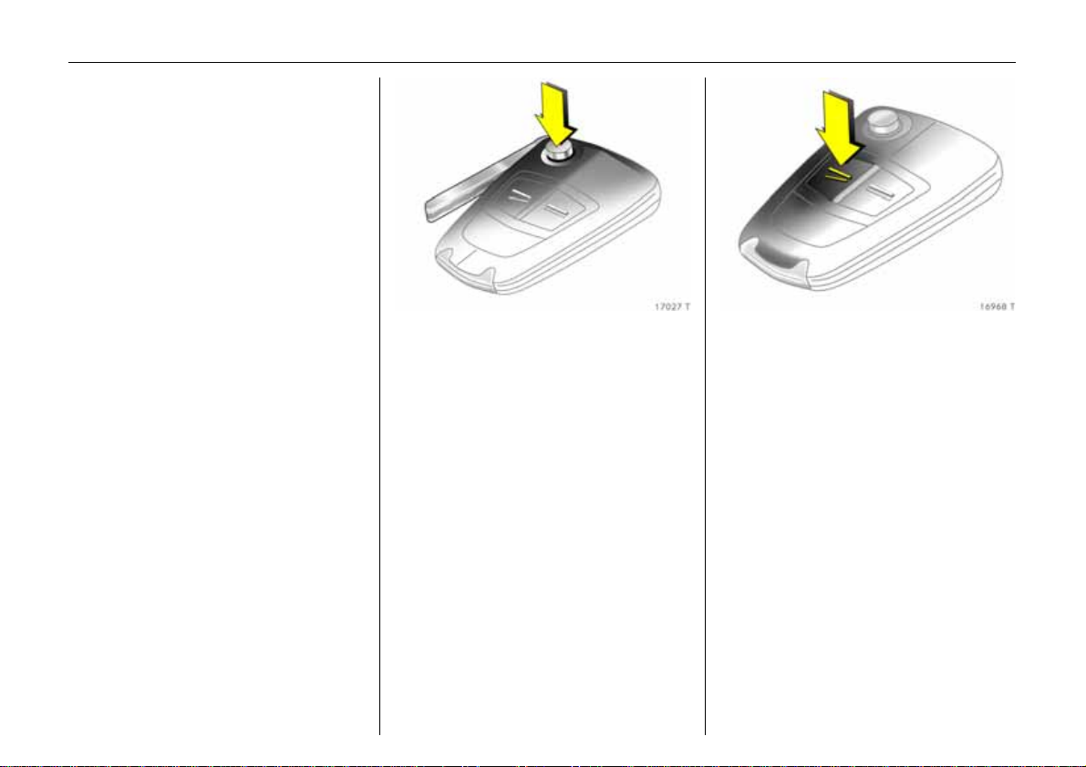
For key with retractable key blade 3, press
button to extend.
6 Further information – see pages 62, 63,
vehicle recommissioning – see page 277.
To unlock and open
the doors:
Press button q,
pull door handle
6 Door locks, child safety locks
– see page 77,
Electronic immobiliser – see page 63,
Keys – see page 62,
Radio remote control – see page 64,
programming unlocking mode
– see page 67,
Central locking system – see page 66,
Anti-theft locking system 3 – see page 66,
Vauxhall alarm system 3 – see page 74.
Page 7
3In Brief
Unlock luggage compartment
and open:
Press button q on the
remote control,
press button and
with the estate pull button
beneath the handle
6 Radio remote control – see page 64,
central locking – see page 66,
programming unlocking mode
– see page 67,
vauxhall alarm system 3 – see page 74,
electrically operated tailgate 3
– see page 71.
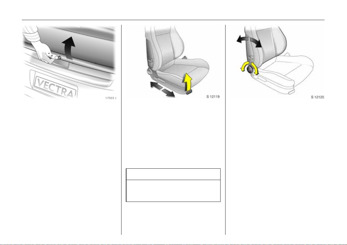
To adjust front seats:
Pull handle,
slide seat,
release handle
Never adjust the seat while driving. It could
move in an uncontrolled manner when the
handle is pulled.
6 Seat position – see page 81,
electrically adjustable front seats
– see page 84.
9 Warning
Important: Do not sit nearer than 10
inches (25 cm) from the steering wheel, to
permit safe airbag deployment.
Adjust front seat backrests:
Turn handwheel
Move backrest to suit seating position.
Do not lean on seat backrest whilst
adjusting it.
6 Seat position – see page 81,
fold front passenger seat backrest
– see page 95,
electrically adjustable front seats
– see page 84.
Page 8
4In Brief
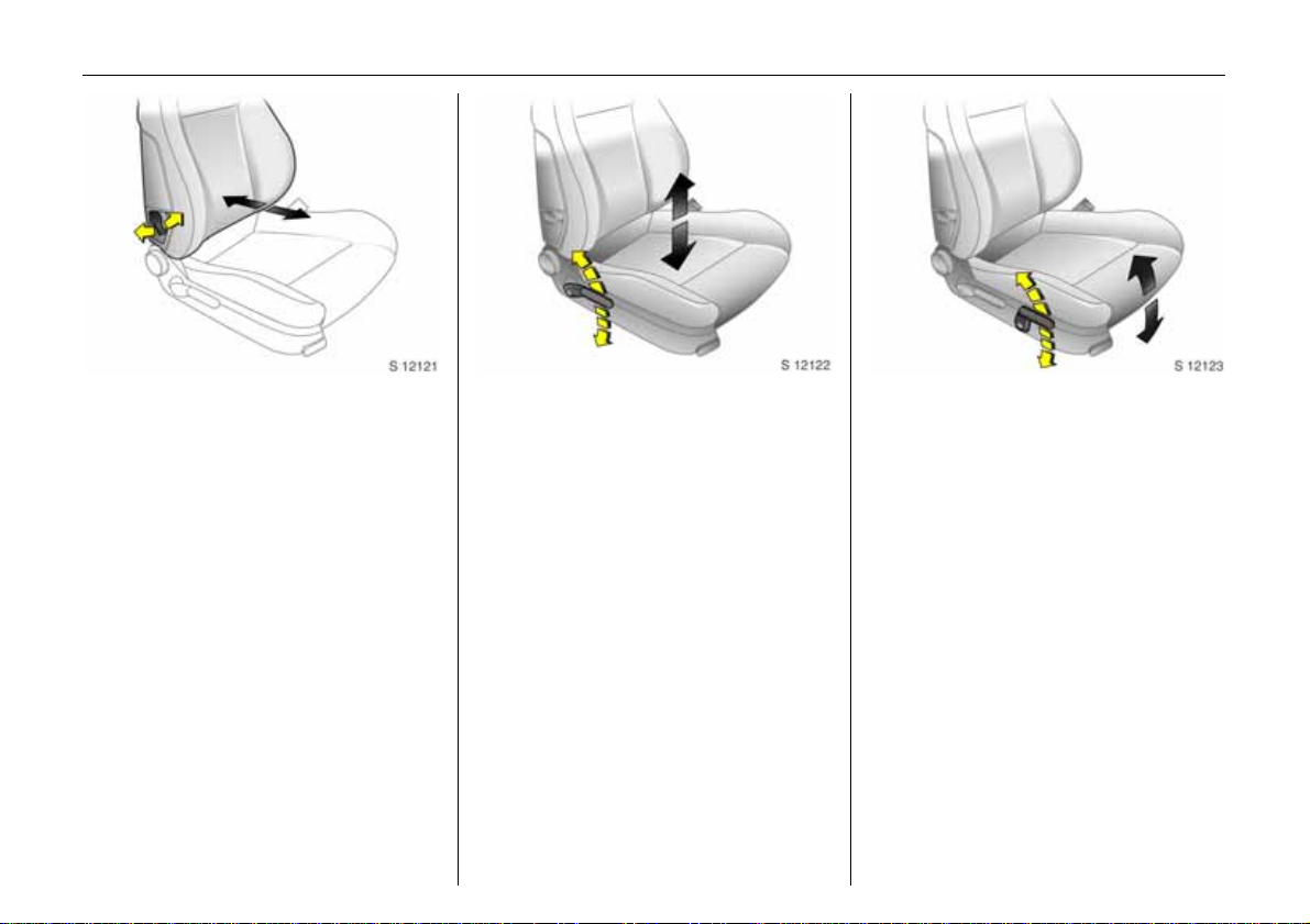
To adjust front seat lumbar
support 3 at front seats:
Operate lever
Adjust lumbar support to suit personal
requirements.
Do not lean on seat backrest whilst
adjusting it.
6 Seat position – see page 81,
electrically adjustable front seats
– see page 84.
To adjust front seat height 3:
Operate lever on
outboard side of seat
Pump direction of the lever
Up: Raises seat
Down: Lowers seat
Do not adjust driver’s seat whilst driving.
6 Seat position – see page 81,
electrically adjustable front seats
– see page 84.
To adjust front seat inclination 3:
Operate front lever on
outboard side of seat
Pump direction of the handle
Up: Inclines seat
Down: Levels seat
Do not adjust driver’s seat whilst driving.
6 Seat position – see page 81,
electrically adjustable front seats
– see page 84.
Page 9
5In Brief
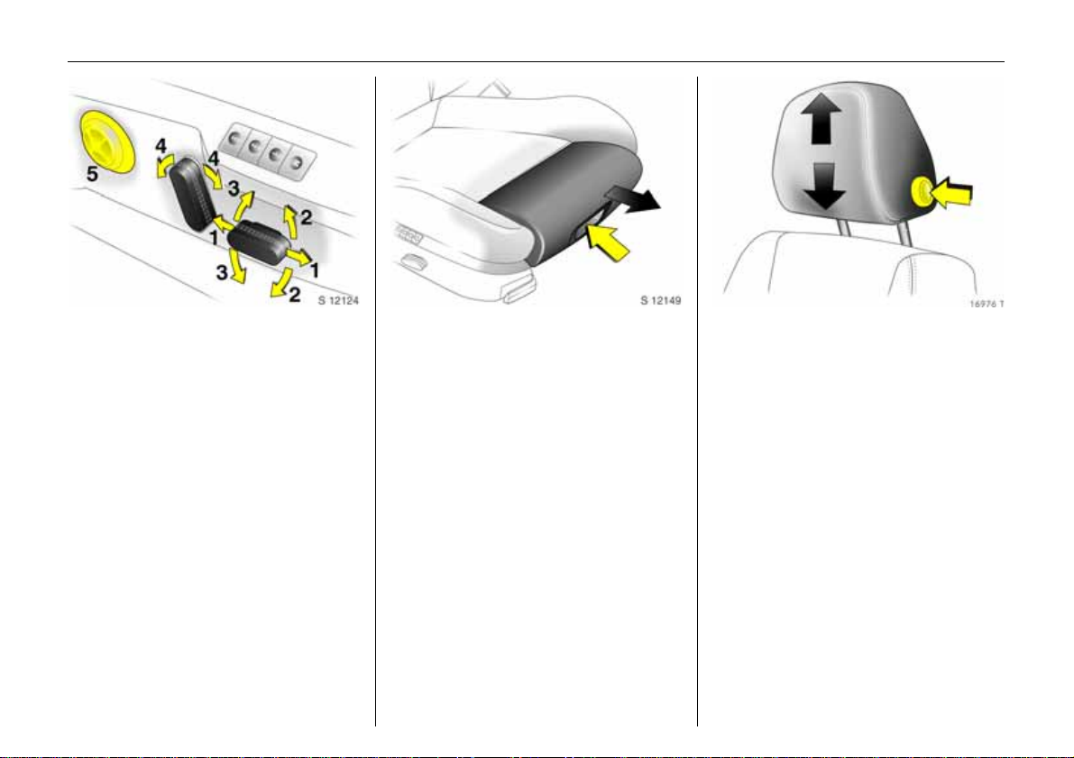
Electric seat adjustment 3:
Operate switch on outboard side
of seat
1 Adjusting the longitudinal position
2 Adjusting the inclination
3 Height adjustment
4 Backrest adjustment
5 Lumbar support 3
Do not adjust driver’s seat whilst driving.
6 Seat position – see page 81,
electrically adjustable front seats
– see page 84.
To adjust thigh support 3
of the front sport seat 3:
Press button in recessed handle
centred in the lower half of the
adjustment cushion and
adjust the thigh support
Adjust thigh support to suit personal
requirements.
Do not adjust the thigh support whilst
driving.
To adjust head restraint height of
front and rear outboard seats 3:
Press button to release,
adjust height,
engage in position
6 Adjusting rear centre
head restraint – see page 82,
head restraint position – see page 82,
head restraint removal – see page 82.
Page 10
6In Brief
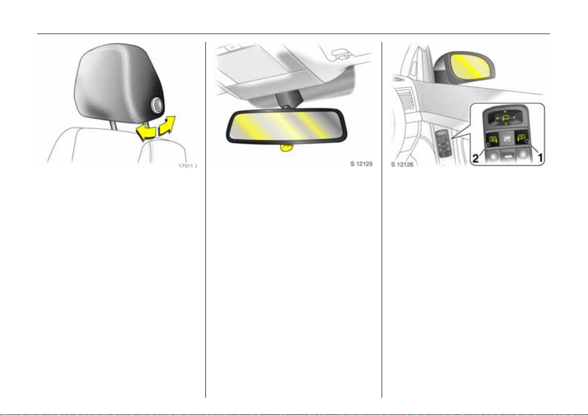
To adjust 3 head restraint
angle of front and rear outboard
seats 3:
Swivel bottom edge of head
restraint forward or rearward
6 Head restraint position – see page 82,
rear head restraints – see page 82.
Adjusting interior mirror:
Swivel mirror housing
Swivel lever on underside of mirror housing
to reduce dazzle at night.
6 Automatic anti-dazzle interior mirror
– see page 126.
To adjust exterior mirrors:
Four-way switch in driver’s door
If the outer mirror switch is pressed 1 the
four-way switch operates the driver and
front passenger mirrors 3, and if the inner
mirror switch is pressed 2 it only operates
the front passenger mirror.
With electric seat adjustment with memory
function 3:
If the interior mirror switch 2 is pressed the
exterior passenger mirror automatically
points at the rear tyres as a parking aid
when reverse gear is selected (not with
trailer attached) 3.
6 Further information, aspherical exterior
mirrors 3 – see page 126,
automatic anti-dazzle exterior mirrors
– see page 126,
heated exterior mirrors – see page 18,
electric seat adjustment 3 – see page 85.
Page 11
7In Brief
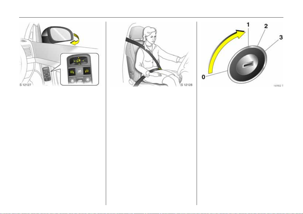
Swing in exterior mirror:
Manually: press lightly.
Electric 3 (both mirror switches must not be
latched into position):
Push four-way switch to the right: outside
rear view mirrors swivel in.
Push four-way to the left: outside rear view
mirrors swivel out.
The mirrors can be retracted from the
outside: Press button p on the remote
control approx. 1 second. The mirrors will
be extended the next time the vehicle is
unlocked.
Swivelling only allowed at speeds of up to
4mph (7km/h).
To engage seat belt:
Draw seat belt smoothly from
inertia reel, guide over shoulder
and engage in belt buckle
The belt must not be twisted at any point.
The lap belt must lie snugly against the
body. The backrest must not be tilted back
too far (recommended tilting angle
approx. 25°).
To release belt, press red button on belt
buckle.
6 Seat belts – see pages 106 to 110,
airbag systems 3 – see page 112,
seat position – see page 81.
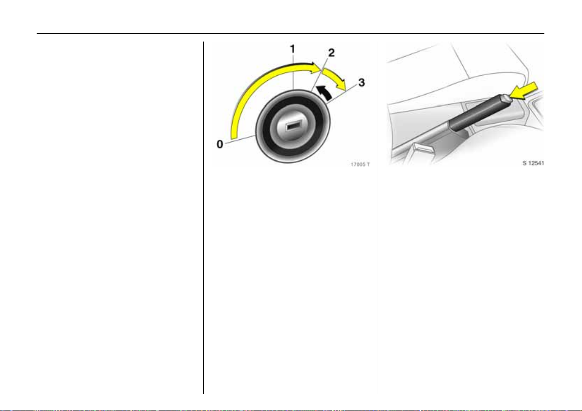
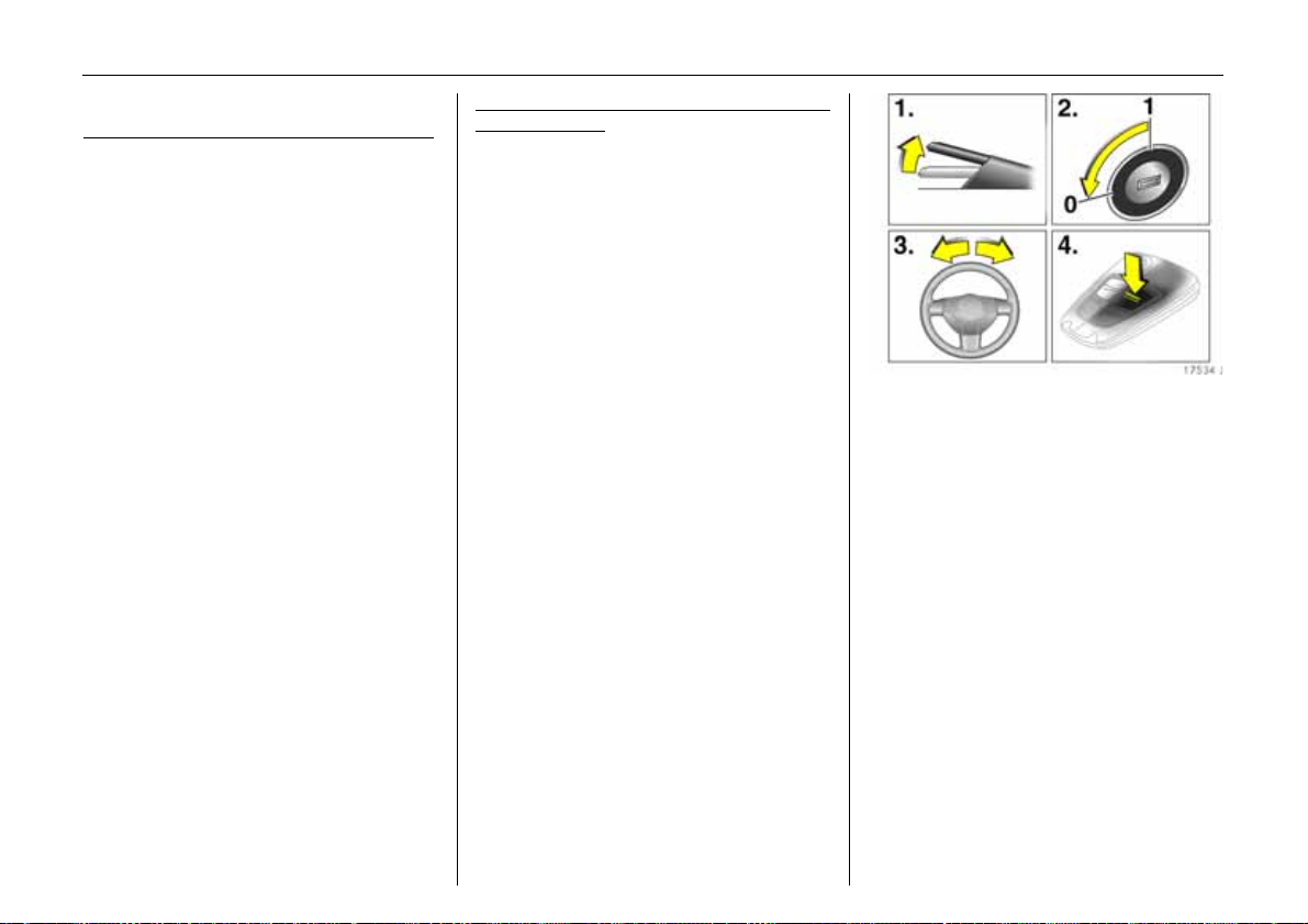
To disengage steering column
lock:
To release the lock,
move the steering wheel slightly,
turn key to position 1
Positions:
0 = Ignition off
1 = Steering released, ignition off
2 = Ignition on,
with diesel engine: preheating
3=Start
6 Starting – see page 21,
electronic immobiliser – see page 63,
remove key and lock steering wheel
– see page 22.
Page 12
8In Brief
Page 13

9In Brief
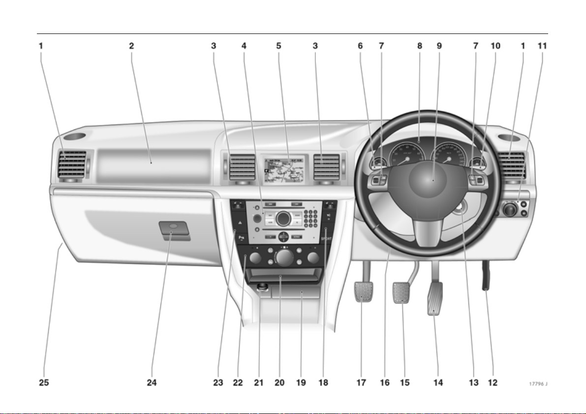
1 Side air vents ..................................144
Page
2 Front passenger airbag ................ 112
3 Centre air vents ............................. 144
4 Infotainment system 3 ................... 59
5 Central information display for
time, date, outside temperature,
infotainment system 3
check control 3,
trip computer 3,
climate control system 3................. 42
6 Turn signal lamps ............................ 15
Headlamp flash,
Dipped and main beam .................. 14
Door-to-door light function 3 .......132
Parking lamps ............................... 132
Cruise control 3 .............................. 202
7 Remote control 3 for
infotainment system ........................ 60
8 Instruments ....................................... 34
9 Horn .................................................. 16
10 Windscreen wiper,
windscreen wash system,
headlamp wash system 3 and
rear window wash system 3 ........... 16
11 Parking lamps, dipped beam .......128
Instrument illumination ................. 133
Fog tail lamp .................................. 130
Fog lamps 3 ................................... 130
Headlamp range adjustment 3 ....129
12 Bonnet release lever ........................ 80
13 Ignition lock with steering
wheel lock .......................................... 7
14 Accelerator pedal ......................... 186
15 Brake pedal ........................... 187, 210
16 Steering wheel adjustment ............ 14
17 Clutch pedal 3............................... 187
18 Right heated seat 3 and
Seat climate control 3 ................... 145
Vauxhall alarm system 3 ............... 74
Rear window blind 3 .................... 141
and
Electronic Stability Program 3 ..... 198
SPORT mode 3 ............................. 200
Ashtrays ......................................... 102
19
20 Stowage compartment 3
with AUX input 3 ............................ 60
21 Cigarette lighter 3 or socket ........ 101
22 Climate control .............................. 165
Page
23 Heated seat (left) 3 and
Page
seat climate control ...................... 145
Hazard warning lamps .................. 16
Parking distance sensor 3 ........... 204
24 Glove compartment ............. 103, 134
25 Fuse box ......................................... 246
Page 14

10 In Brief
Control indicators
O Turn signal lights,
see pages 15, 34.
I Engine oil pressure,
see page 34.
R Brake system,
Clutch system,
see pages 35, 212, 272.
p Alternator,
see page 35.
v Airbag systems,
Belt tensioners,
see pages 108, 117.
W Coolant temperature,
see pages 35, 41.
8 Exterior lights,
see pages 35, 128.
1 Sport programme
of automatic transmission 3
or Easytronic 3,
see pages 173, 182.
T Winter programme of
automatic transmission 3
or Easytronic 3,
see pages 174, 182.
( Door open 3,
see page 36.
j Easytronic 3,
Start engine 3,
see page 171.
t Bulb replacement 3,
see pages 36, 252.
s Open luggage compartment,
see pages 36, 70.
> Fog lights 3,
see pages 36, 130.
C Main beam,
see pages 14, 36.
r Fog tail light,
see pages 36, 130.
r Parking distance sensor 3,
Fault,
see page 204.
u Continuous
Damping Control 3,
Fault,
see page 200.
X Seat belt 3,
see page 36.
A Engine electronics,
Immobiliser,
Transmission electronics 3,
Diesel fuel filter 3,
Fault,
see pages 37, 63, 196.
! Preheating system 3,
Diesel particle filter 3,
see page 37.
H Coolant fluid level,
see pages 37, 271.
u Anti-lock brake system,
see page 213.
Page 15

11In Brief
p Electro-hydraulic power assisted
steering,
Fault,
see page 37.
v Electronic Stability Programme
Plus
(ESP®
see page 198.
) 3,
y Seat occupancy recognition 3,
see page 118.
S Engine oil level,
see pages 38, 268.
m Cruise control 3,
see page 202.
Y Fuel level,
see pages 38, 41, 229.
Z Exhaust emission 3,
see pages 38, 195.
w Tyre pressure monitoring
system 3,
see pages 38, 206.
B Adaptive driving light
(Adaptive Forward
Lighting = AFL) 3,
Fault,
see pages 38, 131.
Lighting
Light switch,
Stalk positions,
see pages 14, 128,
7 Lights off,
8 Parking lights,
9 Dipped beam, main beam.
AUTO Automatic dipped beam
activation 3,
see page 129.
> Fog lights 3,
see pages 36, 130.
r Fog tail light,
see pages 36, 130.
C Main beam,
see page 14.
O Turn signal lights,
see page 15.
k Instrument illumination,
see page 133.
? Headlight range adjustment 3,
see page 129.
c Interior lighting,
see page 133.
a Reading lights, front 3,
see page 133.
¨ Hazard warning lights,
see page 16.
Page 16

12 In Brief
Climate control
x Air flow,
see pages 147, 163.
Air distribution,
see pages 147, 162,
L to head area via adjustable
air vents and to foot well,
M to head area via
adjustable air vents
front and rear 3,
l to the windscreen and
the front door windows,
J to the windscreen, to the
front door windows and
to the footwell,
K to foot well.
V Demisting and defrosting 3,
see pages 152, 157, 161.
Ü Heated rear window,
see page 145.
n Air conditioning system 3,
see page 150.
4 Air recirculation system 3,
see page 150.
A Automatic control of fan
speed 3,
see page 159.
AUTO Automatic mode 3,
Climate control system,
see page 159.
ß Heated seats 3,
see page 145.
A Driver’s seat with climate
control 3,
see page 146.
b Remote control
of auxiliary heating/
ventilation 3,
see page 165.
Sun roof 3
ü Sun roof,
opening – see page 139.
d Sun roof,
closing – see page 139.
f Sun roof,
comfort setting – see page 139.
e Sun roof,
raising – see page 139.
Windscreen wiper
Stalk positions,
see page 16,
§ Off,
$ Timed interval wipe, or
automatic wipe
with rain sensor 3,
% Slow,
& Fast .
Page 17

13In Brief
Information display,
Infotainment system 3
Information display,
see page 42.
Ö On button for date and time
and time, see page 44.
; Date and time setting button,
See page 44.
Remote control 3 for
infotainment system,
see page 60.
Cruise control 3
Buttons on turn signal stalk,
see page 202.
m Activate, store,
accelerate,
g Resume stored speed,
decelerate,
§ Deactivate.
Miscellaneous
p Central locking system,
locking – see page 66.
q Central locking system,
unlocking – see page 66.
r Boot lid/tailgate,
unlocking – see page 70.
x Luggage compartment,
unlocking – see page 70.
F Electrically operated tailgate 3,
opening – see page 71.
m Central locking switch,
unlocking,
see page 67.
) Central locking switch,
locking,
see page 67.
Ä Vauxhall alarm system 3,
see page 74.
z Child safety switch 3,
see page 137.
N Rear window blind 3,
see page 141.
r Parking distance sensor 3,
see page 204.
SPORT SPORT mode 3,
see page 200.
j Horn,
see page 16.
T Automatic transmission 3,
Easytronic 3,
Winter programme,
see pages 174, 182.
j Automatic transmission 3,
Selector lever lock,
see page 179.
+ First-aid kit (cushion) 3,
see page 234.
¨ Warning triangle 3:,
see page 234.
Page 18
14 In Brief
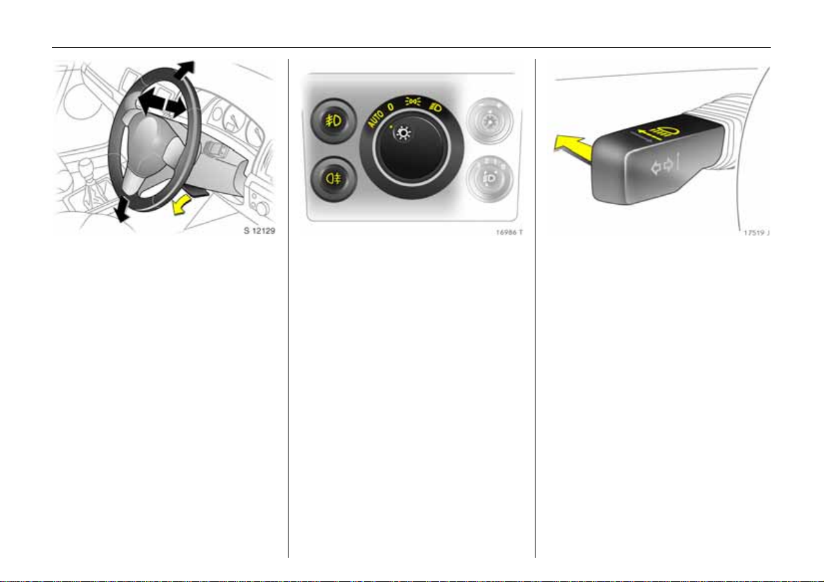
Steering wheel adjustment 3:
Move lever down,
adjust height and distance,
move lever up,
engage
Adjust steering wheel only when vehicle is
stationary and steering column lock is
released.
6 Airbag systems 3 – see page 112.
Light switch:
7 = Off
8 =Parking lights
9 = Dipped or
main beam
AUTO = Automatic
dipped beam
activation 3
Press > = Fog lights 3
Press r = Fog tail light
6 Further information – see page 128,
headlight warning device – see page 22.
Switch between
dipped and main beam:
Main beam = Push stalk
forward
Dipped beam = Push stalk
forward again
or pull toward
steering wheel
The blue control indicator C is illuminated
when main beam is on.
Page 19
15In Brief
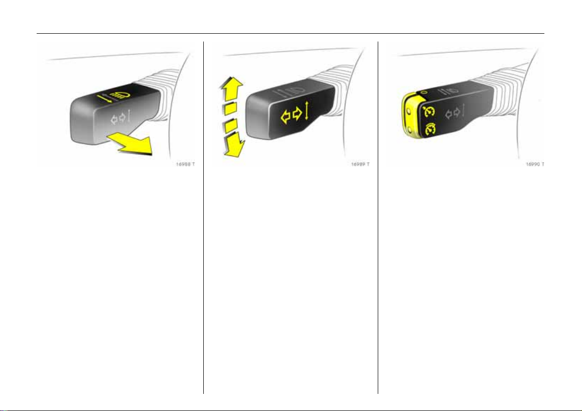
Headlight flash:
Pull stalk towards steering wheel
Turn signals:
Right = Move stalk up
Left = Move stalk down
After operation, the turn signal stalk
returns to its starting position.
If the stalk is moved past the resistance
point, the turn signal light remains on.
When the steering wheel moves back
toward the straight-ahead position, the
turn signal light is automatically
deactivated.
Tap signal: Move stalk to resistance point
and release to activate three flashes from
the turn signals when changing lanes or the
like.
If the stalk is moved past the resistance
point the turn signal remains on.
Switch the turn signal off manually by
moving the stalk slightly.
To operate cruise control 3:
Press buttons on stalk
Switch on: briefly press button m.
Switch off: briefly press button §.
Resume at stored speed: briefly press
button
g.
6 Cruise control 3 – see page 202.
Page 20
16 In Brief
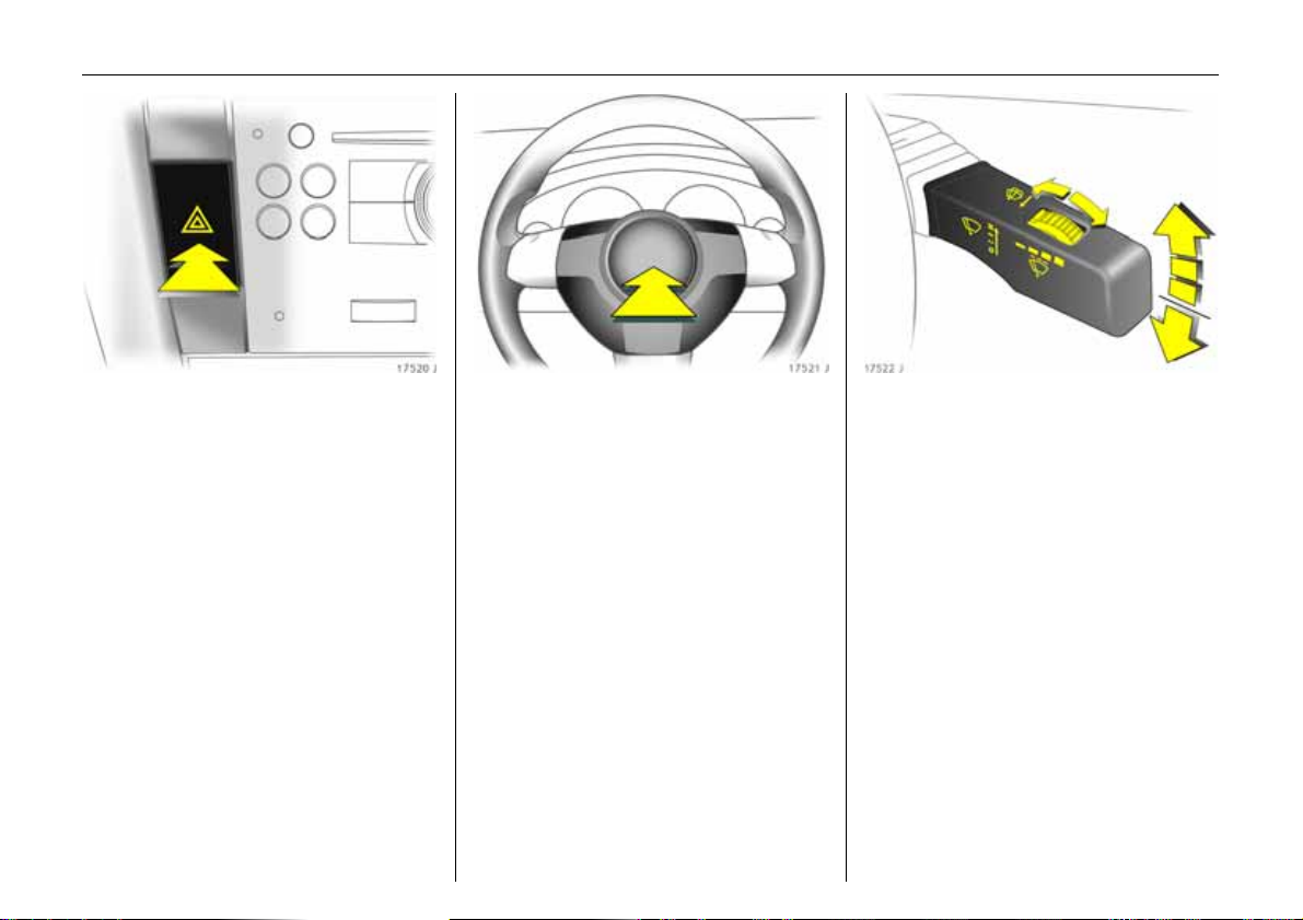
Hazard warning lights:
On = Press ¨
Off = Press ¨ again
To aid location of the pushbutton, the red
surface is illuminated when the ignition
switched on. When the button is pressed,
its control indicator flashes in time with the
hazard warning lights.
To operate horn:
Press j in middle of steering
wheel
6 Airbag systems 3 – see page 112,
Remote control for
Infotainment system 3 – see page 60.
Windscreen wiper:
Gently tap stalk upward
§ = Off
$ = Adjustable timed
interval wipe
% = Slow
& = Fast
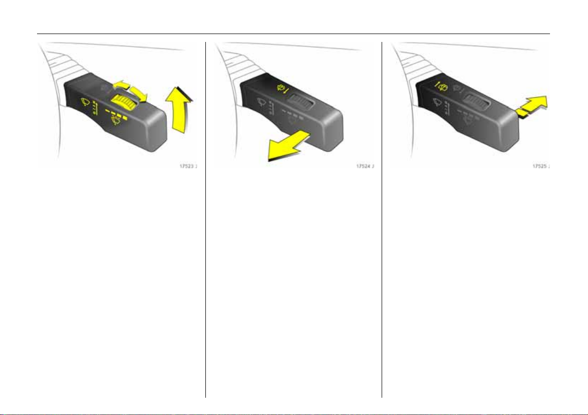
Stalk always moves back to starting
position. Shift to next higher or lower level:
move stalk slightly.
Push stalk past resistance point and hold:
the windscreen wiper stages are run
through; an acoustic signal sounds at
position §.
Adjustable interval wipe $:
Shorter intervals = turn adjuster wheel to
right
Longer intervals = turn adjuster wheel to
left
Press the stalk down from position §: Single
swipe.
6 Further information – see
pages 273, 274, 279.
Page 21
17In Brief
Automatic wiping with rain
sensor 3:
Move stalk upward
$ = automatic wiping
with rain sensor
Automatic wiping $: the rain sensor
detects the quantity of water on the
windscreen and automatically controls the
windscreen wiper. The sensitivity of the
system can be adjusted using the adjuster
wheel:
Automatic wiping $:
Less sensitive = to the left
More sensitive = to the right
To switch off, move stalk downwards.
6 Further information – see
pages 273, 274, 279.
Operating windscreen and
headlight wash systems 3:
Pull stalk towards steering wheel
The wiper is switched on for several wipe
operations. A single after-wipe occurs at
speeds of up to 80 mph (130 km/h).
The headlight wash system 3 is ready for
operation when the headlights are
switched on. Wash fluid is sprayed onto the
headlights once. Then the headlight wash
system is disabled for 2 minutes.
On vehicles fitted with rain sensor 3, keep
the sensor area clean.
6 Further information – see
pages 274, 279.
Rear window wiper 3 and
wash system 3 operation:
Wiper on = Push stalk
forward
Wiper off = Push stalk
forward again
Wash = Press and hold
The rear window wiper operates in
intermittent mode. Rear window wiping
takes place automatically with the
windscreen wiper switched on and reverse
gear selected.
When washing, the wiper swipes for a few
strokes. At low speeds, there is a one-time
post-wash swipe.
The rear window wash system is
deactivated when the fluid level is low.
6 Further information – see
pages 273, 274, 279.
Page 22
18 In Brief
Heated rear window,
heated exterior mirrors:
On = Press Ü
Off = Press Ü again
Heating operational only with engine
running.
The rear window and exterior mirror
heating is switched off automatically after
approx. 15 minutes.
6 Further information – see page 145.
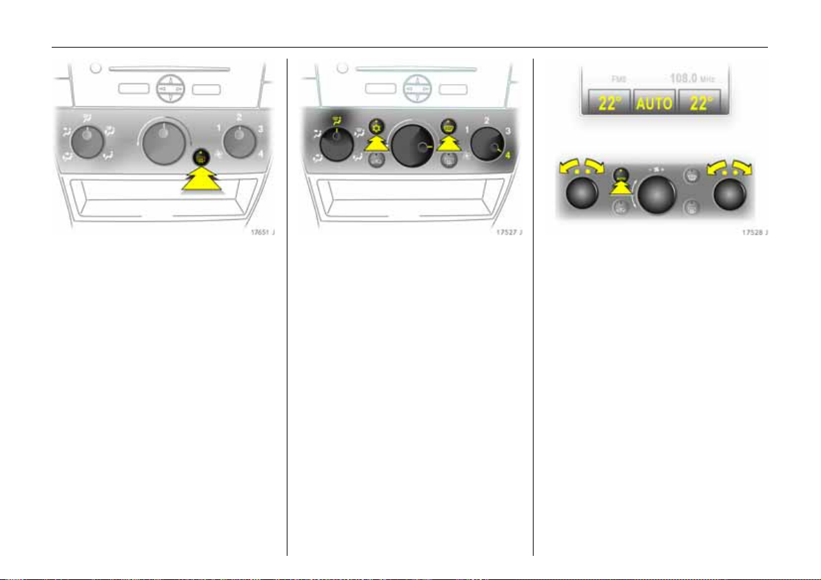
To demist or defrost windows:
Set air distribution to l,
rotary switch for temperature
and air flow clockwise;
Air conditioning system 3:
Press buttons n and V,
climate control system 3:
Press buttons n and V,
turn rotary switch for
temperature clockwise,
air flow to A;
Climate control system 3:
Press button V
Open front air vents, direct side air vents
towards the door windows. Close centre air
vents 3.
6 Climate control – see page 142.
Setting automatic mode of
climate control system 3:
Press AUTO button,
set temperature for driver and
passenger sides using left and
right rotary knobs
All front air vents open. If desired, the rear
vents also 3.
6 Climate control system 3 – see
page 158.
Page 23
19In Brief
Range
Inst. consumpt.
19,5° 23° 5 Eco x 19:36
257
21.3
miles
miles/gal
Information display:
Display the information
–Time,
– outside temperature,
–radio3 and date,
– navigation 3,
– telephone 3,
– check control 3,
–trip computer3,
– climate control system 3.
6 Info Display – see page 42.
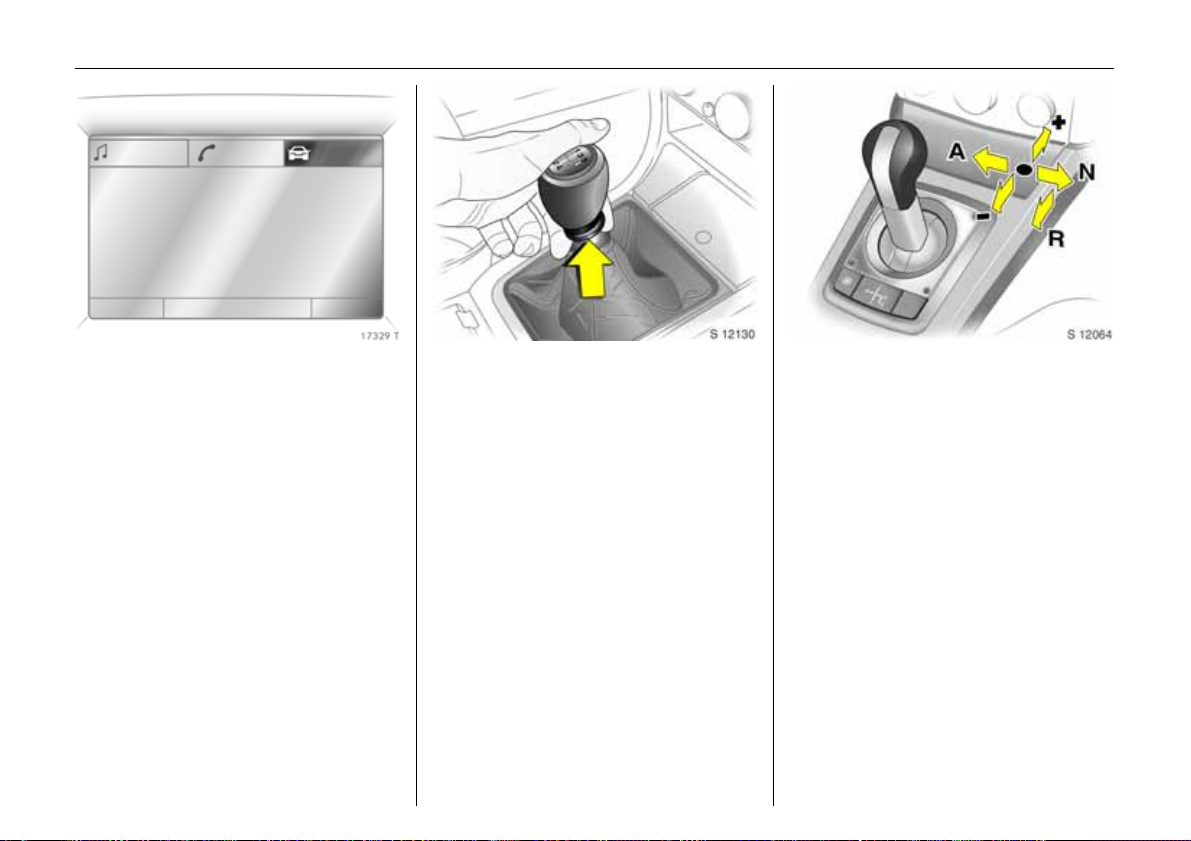
Manual transmission:
Reverse gear: with vehicle stationary, three
seconds after de-clutching, pull the ring up
and engage gear.
If the gear does not engage, set the lever in
neutral, release the clutch pedal and
depress again; then repeat gear selection.
Easytronic 3:
N = Idle
o =Drive position
+ =Higher gear
- = Lower gear
A = Change between
Automatic and
Manual mode
R =Reverse
(with selector lever lock)
The selector lever must always be moved in
the appropriate direction as far as it will
go. Upon release, it automatically returns
to the centre position. Pay heed to the
gear/mode indicator in the transmission
display.
The foot brake must be depressed when
starting.
6 Easytronic 3 – see page 170.
Page 24
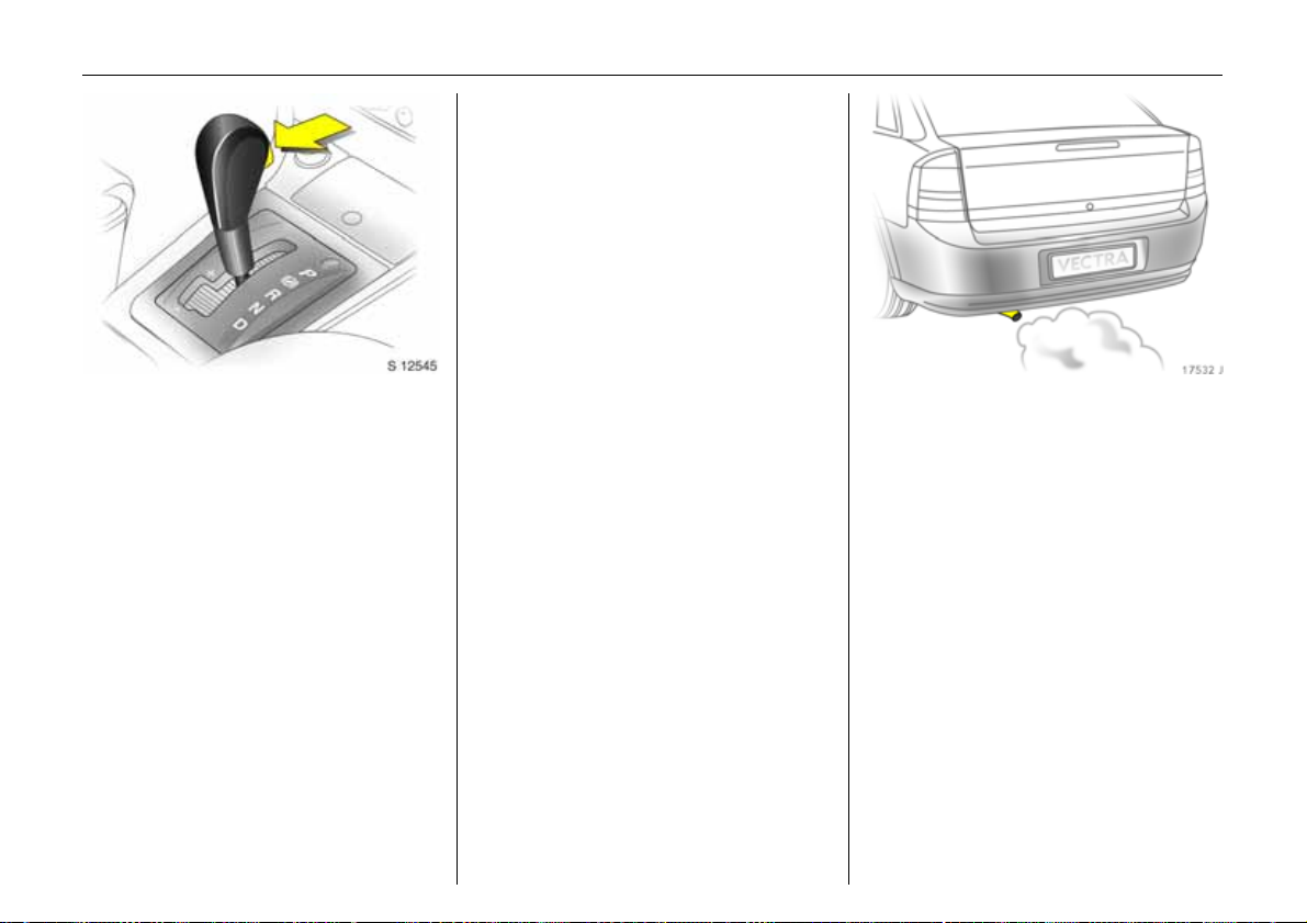
20 In Brief
In order to leave P switch on ignition,
operate foot brake and press button on
selector lever.
To engage P or R, push button on selector
lever.
P: Only with vehicle stationary, first
apply hand brake
R: Only with vehicle stationary
6 Automatic transmission 3
– see page 178.
Automatic transmission 3:
P =Park position
R = Reverse gear
N = Neutral position (idling)
D = Automatic gear selection
Selector lever in D to the left:
Manual mode
+ = Higher gear or stage
- =Lower gear
or stage
P or N must be engaged when starting.
Exhaust gases are poisonous
Exhaust gases contain carbon monoxide,
which is extremely poisonous but is
odourless and colourless.
Therefore never inhale exhaust gases, and
never run the engine in an enclosed space.
Avoid driving with an open luggage
compartment. Otherwise, exhaust gases
could penetrate the interior.
Page 25
Before starting off, check:
z Tyre pressure and condition
– see pages 206, 215, 299.
z Engine oil level and fluid levels in engine
compartment – see pages 267 to 275.
z All windows, mirrors, exterior lighting
and number plates are free from dirt,
snow and ice and operational.
z Do not place any objects in front of the
rear window, on the instrument panel or
in the area in which the airbags inflate.
z Seats, seat belts and mirrors are
correctly adjusted.
z Check brakes.
To start engine:
Operate clutch and brake,
automatic transmission 3 in P
or N,
Easytronic 3: Depress brake,
do not accelerate;
Petrol engine: Turn key to 3;
Diesel engine: Turn key to 2, when
control indicator ! goes out1),
turn key to 3;
Release key once engine is
running
To restart or switch off the engine, turn key
back to 0.
To switch on the ignition, only turn the key
to 2.
21In Brief
Releasing the hand brake:
Raise lever slightly,
press lock button,
lower lever fully
To reduce operating forces, depress foot
brake at the same time.
And now "Have a good journey!"
Drive carefully, economically and with the
environment in mind. While driving, do not
do anything that could distract you.
1)
Preheating system switches on only if outside
temperature is low.
Page 26
22 In Brief
Warning buzzers
When starting the engine or whilst driving:
z if seat belt is not fastened 3,
z if a door or the tailgate is ajar,
z once you have reached a certain speed if
the hand brake is applied 3,
z if a specified maximum speed is
exceeded 3,
z for Easytronic 3 - if A, M or R is selected
while the engine is running and the
driver’s door is opened but the foot
brake is not depressed.
When the vehicle is parked and the driver’s
door is opened:
z When the key is in the starter switch 3,
z with parking lights or dipped beam
switched on
z with Easytronic 3 – if the hand brake is
not applied and no gear is engaged
when the engine is off
Parking the vehicle:
Apply handbrake firmly,
engine off,
remove key,
lock steering wheel,
lock vehicle
To lock and activate Vauxhall alarm
system 3 press button p. To activate the
anti-theft locking system 3 press button p
again.
6 Further information – see pages 63, 186,
radio remote control – see page 64,
central locking system – see page 66,
Vauxhall alarm system 3 – see page 74,
vehicle decommissioning – see page 277.
Page 27

23In Brief
Advice when parking:
z Do not park vehicle on easily ignitable
surfaces, since the hot exhaust system
temperatures could cause the surface to
ignite.
z Closing windows and sun roof 3.
z Always apply the hand brake fully,
raising the armrest 3 when doing so.
When parking on an incline, pull the
hand brake as far as it will go. To reduce
operating forces, depress the foot brake
at the same time.
z Before switching off ignition: with
manual transmission, engage first or
reverse gear; with automatic
transmission 3, selector lever in P; with
Easytronic 3 engage first or reverse gear
(note gear indicator – see page 171).
z On vehicles with Easytronic 3 control
indicator R flashes for a few seconds
after the ignition is switched off if the
hand brake has not been applied
– see page 175.
z In vehicles with automatic
transmission 3 the key can only be
removed when the selector lever is in
position P.
z Remove ignition key.
z Turn steering wheel until lock is felt to
engage (anti-theft protection).
z The engine cooling fans may run after
the engine has been switched off
– see page 267.
6 Further information – see
pages 276, 277.
Page 28
24 In Brief
Service work,
Maintenance
We recommend that you entrust all work to
your Vauxhall Authorised Repairer, who
can provide you with reliable service and
correctly perform all work according to
factory instructions.
6 Vauxhall Service – see page 264,
service interval display – see
pages 39, 266.
Genuine Vauxhall Parts and
Accessories
We recommend that you use "Genuine
Vauxhall Parts and Accessories" and
conversion parts approved expressly for
your vehicle type. These parts have
undergone special tests to establish their
reliability, safety and specific suitability for
Vauxhall vehicles. Despite continuous
market monitoring, we cannot assess or
guarantee these – attributes for other
products, even if they have been granted
approval by the relevant authorities – or in
some other form.
"Genuine Vauxhall Parts and Accessories"
and conversion parts approved by
Vauxhall can be obtained from your
Vauxhall Authorised Repairer, who can –
also provide expert advice on permitted
technical changes – and ensure correct
installation.
9 Warning
Carry out regularly the checks
recommended in the individual sections
of this Owner’s Manual.
Ensure that your vehicle is serviced at the
service intervals specified in the Service
Booklet. We recommend that you entrust
this work to your Vauxhall Authorised
Repairer.
Have faults remedied without delay!
Consult a workshop. We recommend your
Vauxhall Authorised Repairer. If
necessary, interrupt your journey.
6 Maintenance – see page 266.
Page 29

25In Brief
That was the most important
information for your first drive in
your Vectra in brief.
The other pages of this chapter
contain a summary of the
interesting functions in your
vehicle.
The remaining chapters of the
Owner’s Manual contain
important information on
operation, safety and
maintenance as well as a
complete index.
Page 30
26 In Brief
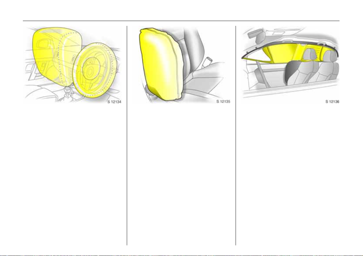
Vauxhall Full Size airbag system
The Vauxhall Full Size airbag system
comprises several individual systems.
Front airbag system
The front airbag system will be triggered in
the event of a serious accident involving a
frontal impact and forms safety cushions
for the driver and front passenger. The
forward movement of the driver and front
passenger is checked and the risk of
injuries to the upper body and head
thereby substantially reduced.
Side airbag system 3
The side airbag system triggers when a
side-on collision occurs and provides a
safety barrier for the driver and/or
passenger in the respective front door
area. This reduces the risk of injury to the
upper body considerably in case of a side
impact.
Curtain airbag system 3
The curtain airbag system triggers in case
of a side-on collision and provides a safety
barrier in the head area on the respective
side of the vehicle. This reduces the risk of
injury to the head considerably in case of a
side-on collision.
6 Airbag systems 3 – see page 112.
Page 31

27In Brief
Active head restraints 3 at front
seats
In the event of a rear-end impact, the
active head restraints automatically tilt
forwards. The head is more effectively
supported by the head restraint and the
risk of injuries caused by whiplash in the
neck area is reduced.
Active head restraints are identified by the
lettering ACTIVE on the head restraint
guide sleeves.
Operating menus in the
information display 3
Menu options are selected using menus
and using the buttons/four-way button or
the multifunction button of the
Infotainment system 3 or the left-hand
adjuster wheel 3 on the steering wheel.
The respective menu options are shown on
the display.
Selection using four-way button:
press four-way button at top, bottom, left
or right.
Selection using multifunction button: rotate
and press multifunction button.
To exit a menu, turn the multifunction
button left or right to Return or Main and
select.
6 Info Display – see page 42.
Page 32

28 In Brief
Selection using left-hand adjuster wheel on
steering wheel: rotate and press adjuster
wheel.
Range
Inst. consumpt.
19,5° 23° 5 Eco x 19:36
257
21.3
miles
miles/gal
Trip computer 3
The trip computers provide information on
driving data, which is continually recorded
and evaluated electronically.
Functions:
z Range
z Instantaneous consumption
z Distance travelled
z Average speed
z Effective consumption
z Average consumption
z Stop watch
z Tyre pressure 3
6 Trip computer – see pages 48, 54.
Coolant level
check
OK
Check control 3
The check control software monitors
z Fluid levels
z Tyre pressure 3
z Radio remote control battery
z Vauxhall alarm system 3
z Important exterior lighting lights,
including cables and fuses
6 Check control – see page 58.
Page 33

29In Brief
Remote control for Infotainment
system 3
The functions of the Infotainment system 3
and the information display can be
operated using the buttons on the steering
wheel.
Further information is available in the
infotainment system operating
instructions.
Twin Audio 3
Twin Audio allows rear seat occupants the
choice between the audio source played on
the infotainment system or a separate
audio source.
Only an audio source that is not currently
active on the infotainment system can be
controlled using Twin Audio.
Two headphone connections are available,
with separate volume controls.
Further information is available in the
infotainment system operating
instructions.
Parking distance sensor 3
When reverse gear is selected, the parking
distance sensor switches itself on
automatically.
The parking distance sensor can also be
activated at speeds of less than 15 mph
(25 km/h) by pressing the
the instrument panel.
If the vehicle approaches an obstacle to
the front or rear, an series of signals is
sounded in the vehicle interior. The interval
between the signals becomes shorter as
the distance is reduced. If the distance is
less than 30 cm, the signal will be
continuous.
6 Further information – see page 204.
r button on
Page 34

30 In Brief
Travel Assistant 3
The Travel Assistant Contains
z Armrest
z Stowage compartments
z Waste container
z Drink holders
z Accessory sockets
z Connection console
e.g. for DVD player 3
z Electric cool box
z Tables
z Twin Audio (rear audio module) 3 or
stowage compartment
The Travel Assistant is installed on a
console above the middle seat in the rear.
6 Further information – see page 87.
Tables
1 Fold armrest up and and use recessed
grip to pull table upwards as far as it
will go.
2 Swivel table forward.
3 Fold table down.
4 Fold armrest down and set the table
to the desired position by sliding it
forward or rearward.
Page 35

Ü Board Computer
BC 1
BC 2
Timer
Tyres
31In Brief
FlexOrganizer 3
The side walls contain retaining strips,
where various components can be
attached to divide the luggage
compartment or fasten loads.
The system consists of
z variable partition net
z variable partition wall
z partition rod
z mesh pockets for the side walls
z hooks
6 Further information – see page 98.
SPORT mode 3
To activate
Press the SPORT button. The LED in the
button illuminates.
SPORT mode is used to change
damping 3, steering 3, throttle
application and the shifting times and
shifting points for Easytronic 3 and
automatic transmission 3 while driving.
Damping and steering become more direct
and provide better contact with the road
surface. The engine reacts more quickly to
accelerator movements.
With Easytronic 3 and automatic
transmission 3, the shift times are
shortened and shifting takes place at
higher revs (not with cruise control
enabled 3).
6 Further information – see page 200.
Tyre pressure monitoring
system 3
The tyre pressure monitoring system
continuously monitors the pressure of all
four tyres while the vehicle is being driven.
A pressure sensor is installed in each wheel.
The inflation pressures of the individual
tyres are transmitted to a controller, where
they are compared.
The current tyre pressures can be
displayed on the graphical information
display or the colour information display 3.
Deviating tyre pressures are displayed in
the form of messages on the information
display whilst driving.
6 Further information – see page 206.
Page 36

32 In Brief
Adaptive Forward Lighting
(AFL) 3
On vehicles with Bi-Xenon headlights,
improves illumination of
z curves (curve lighting)
z intersections and tight turns (turn
lighting)
Curve lighting 1
The Xenon light beam pivots based on
steering wheel position and speed (from
approx. 6 mph / 10 km/h).
The headlights shine at an angle of up to
15° to the right or left of the direction of
travel.
Turn lighting 2
An additional light comes on at certain
steering wheel settings (after approx. 90°),
turn signal settings and speeds (up to
approx. 25 mph / 40 km/h).
The light beam projects at a 90° angle to
the left or right of the vehicle up to a
distance of approx. 30 metres.
Motorway lighting
At higher speeds and continuous straight
ahead travel, the dipped beam
automatically raises slightly, thereby
increasing headlight range.
6 Further information – see page 131.
Page 37

z To close
– Press r on the remote control,
until the tailgate is closed
or
– with the key in the ignition
switch and the hand brake applied,
press button x in the driver’s door until
the tailgate is closed
or
– press button
6 Further information – see page 71.
F in the tailgate.
33In Brief
Electrically operated tailgate 3
z To open
– Press button r on the remote control for
approx.
1 second
or
– with the key in the ignition
switch and the hand brake applied,
press x in the driver’s door approx.
1second
or
– unlock the tailgate and open by pulling
the button under the handle.
Towing equipment with pivoting
coupling ball bar 3
The release lever is in the left stowage
compartment in the luggage
compartment. Open cover.
z Pull release lever downward
– The LED is illuminated as long as the
coupling ball bar is not engaged.
– In addition, a warning buzzer sounds
and the coupling ball bar pivots
downward.
z Pivot the coupling ball bar rearward until
it engages.
–LED must go out
– Warning buzzer must cease
– Otherwise, repeat the procedure.
6 Further information – see page 221.
Page 38

34 Instruments
Instruments
Control indicators ................................ 34
Instrument display............................... 40
Information display ............................. 42
Radio reception 3................................ 59
AUX input 3......................................... 60
Infotainment system 3........................ 60
Remote control for infotainment
system 3 and information display .. 60
Twin Audio 3 ....................................... 60
Electronic data acquisition at toll
systems 3........................................... 61
Mobile telephones and radio
equipment 3...................................... 61
Control indicators
The control indicators described here are
not present in all vehicles. The description
applies to all instrument versions.
O
Turn signal lights
The relevant control indicator flashes when
the turn signal is on.
Both control indicators flash with the
hazard warning lights on.
Rapid flashing: failure of turn signal or
associated fuse. Trailer turn signal
failure 3. For bulb replacement see
page 252, for fuses see page 246.
I
Engine oil pressure
The control indicator illuminates when the
ignition is switched on and goes out shortly
after the engine starts.
Illuminates when the engine is running
Engine lubrication may be interrupted. This
may result in damag e to the engine and/or
locking of the drive wheels:
1. Move out of the flow of traffic as quickly
as possible without impeding other
vehicles.
2. Depress clutch.
3. Shift manual transmission or
Easytronic 3 into neutral; for automatic
transmission 3, set selector lever to N.
4. Switch off ignition.
9 Warning
When the engine is off, considerably
more force is needed to brake and steer.
Do not remove key until vehicle has come
to a standstill, otherwise the steering
column lock could engage unexpectedly.
Consult a workshop. We recommend your
Vauxhall Authorised Repairer.
Page 39

R
Picture no: 18276j.tif
Brake system,
clutch system
The control indicator illuminates when the
ignition is switched on if the hand brake is
applied or if the brake or clutch fluid level is
too low. Further information
– see pages 212, 272.
For vehicles with Easytronic 3, the control
indicator flashes for a few seconds when
the ignition is turned off if the hand brake
is not applied.
9 Warning
If it illuminates when the hand brake is
not applied: Stop the vehicle; interrupt
your journey immediately. Consult a
workshop. We recommend your Vauxhall
Authorised Repairer.
p
Picture no:
Alternator
The control indicator illuminates when the
ignition is switched on and goes out shortly
after the engine starts.
Flashing while starting
Battery voltage too low. Have electrical
system tested in a workshop. We
recommend your Vauxhall Authorised
Repairer.
Illuminates when the engine is running
Stop, switch engine off. Battery is not
charged. Engine cooling may not be
operating. With a diesel engine the brake
servo unit may stop operating. Consult a
workshop. We recommend your Vauxhall
Authorised Repairer.
35Instruments
v
Airbag systems 3,
belt tensioners 3
If it illuminates while driving, there is a fault
in the airbag systems, seat occupancy
recognition 3 or the belt tensioners, see
pages 108, 117.
W
Coolant temperature
Illuminates when the engine is running
Stop and turn engine off, coolant
temperature is too high. Risk of engine
damage. For coolant temperature display
see page 41. Check coolant level
immediately, see page 270.
8
Exterior lights
The control indicator is illuminated when
the exterior lights are on – see page 128.
1
SPORT mode of
automatic transmission 3
or Easytronic 3
The control indicator is illuminated when
SPORT mode 3 is engaged.
Further information – see pages 173, 181.
6
Page 40

36 Instruments
Picture no: 18276j.tif
T
Winter program of
automatic transmission 3
Easytronic 3
Control indicator is illuminated when winter
program is enabled.
Further information – see pages 174, 182.
(
Door open
Illuminates with the doors open.
j
Picture no:
Easytronic 3,
start engine
The control indicator illuminates when the
ignition is turned on if the foot brake is not
operated. It goes off as soon as the foot
brake is operated. The engine can only be
started with the foot brake operated
– see page 171.
t
Bulb replacement 3
A bulb has failed. Check the lights, and
exchange the failed bulb. Bulb exchange
– see page 252.
s
Bootlid open
Illuminates with the luggage compartment
open, close luggage compartment
– see page 70.
>
Fog lights 3
The control indicator is illuminated when
the fog lights are on – see page 130.
C
Main beam
The control indicator illuminates if the main
beam is on and during headlight flash
– see pages 14, 128.
r
Fog tail light
The control indicator is illuminated when
the fog tail light is on – see page 130.
r
Parking distance sensor 3
see page 204.
u
Continuous Damping Control 3,
SPORT mode
see page 200.
X
Seat belt 3
The control indicator illuminates when the
ignition is switched on and remains
illuminated until the seat belt is fastened. If
the seat belt is not yet fastened after
driving off, an acoustic warning also
sounds. Fastening the seat belt
– see page 109.
Page 41

37Instruments
A
Engine electronics,
transmission electronics 3,
diesel fuel filter 3,
immobiliser
Illuminates when the engine is running
Fault in engine electronics or transmission
electronics. Electronics switch to
emergency running programme, fuel
consumption may increase and driveability
of the vehicle may be impaired
– see page 196. Consult a workshop
immediately. We recommend your
Vauxhall Authorised Repairer.
1)
Diesel engines
Z 19 DTH: Have water drained from diesel
fuel filter, see page 270.
Flashes when the ignition is on
Fault in the electronic immobiliser system;
the engine cannot be started
– see page 63.
Z19DTL, Z19DT,
!
Preheating system 3,
Diesel particle filter 3
Lights
Preheating system active, switches on only
if outside temperature is low.
Flashing
Diesel particle filters must be cleaned.
Continue driving and as soon as the road
and traffic conditions permit it, increase
speed to more than 25 mph (40 km/h), at
which point diesel particle filter cleaning
will start. The control indicator goes off as
soon as cleaning is complete. We
recommend leaving the ignition switched
on during the cleaning.
Further information – see page 197.
(with diesel particle filter)
H
Coolant level
Illuminates when the engine is running
Coolant fluid level too low. Stop, turn off
engine. Check coolant fluid level
immediately, see page 271.
u
Anti-lock brake system
see page 212.
p
Electro-hydraulic power assisted steering
Fault in electro-hydraulic steering system.
Power steering may not work. Vehicle can
still be steered, but considerably more
force is required. We recommend you
consult your Vauxhall Authorised Repairer.
v
Electronic Stability
Programme (ESP®
see page 198.
y
Seat occupancy recognition 3
see page 118.
Plus
) 3
1)
Sales designation – see page 284
Page 42

38 Instruments
S
Picture no: 18276j.tif
Engine oil level 3
Illuminates when the engine is running
Engine oil level too low. Check engine oil
level and top up engine oil if necessary
– see page 268.
m
Cruise control 3
see page 202.
Y
Fuel level
Lights
Low fuel level, fuel gauge in reserve area.
Flashing
Fuel supply exhausted, refuel immediately.
Never let the tank run dry!
Petrol engines: erratic fuel supply can
Picture no:
cause catalytic converter to overheat
– see page 193.
Diesel engines: If the tank is run dry, bleed
the fuel system as described on page 229.
Z
Exhaust gases 3
The control indicator illuminates when the
ignition is switched on and goes out shortly
after the engine starts.
Illuminates when the engine is running
Fault in emission control system. The
permitted emission limits may be
exceeded. Consult a workshop. We
recommend your Vauxhall Authorised
Repairer.
If it flashes when the engine is running:
Fault that can lead to destruction of the
catalytic converter is indicated
– see page 195. Consult a workshop
immediately. We recommend your
Vauxhall Authorised Repairer.
w
Tyre pressure monitoring system 3
Illuminated red
Tyre pressure difference, check tyre
pressure at next opportunity.
Flashes red
Considerable pressure difference or direct
loss of pressure, stop immediately and
check tyres and tyre pressure.
Illuminated yellow
Fault in system, consult a workshop. We
recommend your Vauxhall Authorised
Repairer.
Tyre pressure monitoring system
– see page 206.
B
Adaptive Forward Lighting 3 (AFL)
System fault. In the event of malfunction of
the curve lighting pivot function, the
releveant dipped beam light is
deactivated. Consult a workshop. We
recommend your Vauxhall Authorised
Repairer.
AFL – see page 131.
Page 43

39Instruments
Transmission display 3
Picture no: 17536j.tif
Display of the selected gear position
with automatic transmission 3
or the selected gear with Easytronic 3:
P Park position of automatic
transmission.
R Reverse gear.
N Neutral or idling position.
A Automatic mode of Easytronic.
M Manual mode of Easytronic.
D Automatic mode of
automatic transmission.
1-5 Manual mode, current gear for
Easytronic.
1-5 and
1-6 3 Manual mode, selected gear
with automatic.
For Easytronic 3, the display flashes for a
few seconds if A, M or R is selected when
the engine is running but the foot brake is
not depressed.
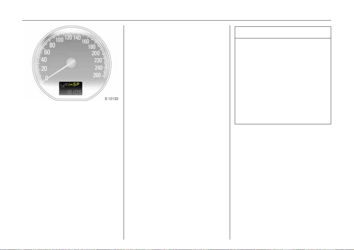
Picture no: 17858j.tif
InSP
Service interval display 3
When InSP appears in the odometer
display, make an appointment with a
workshop for servicing as soon as possible.
We recommend your Vauxhall Authorised
Repairer.
Maintenance, inspection system
– see page 266.
Page 44

40 Instruments
Odometer
Records the miles driven.
Display in the event of airbag system
malfunction – see page 117.
Trip odometer
To set to zero, hold reset knob down for
approx. 2 seconds with ignition switched
on.
Instrument display
Picture no: 17537j.tif
On some versions, the pointer of the
tachometer, speedometer and fuel gauge
briefly moves to its end position when the
ignition is switched on.
Tachometer
Picture no:
Indicates engine speed.
Warning zone: Maximum permissible
engine speed exceeded; danger to engine.
Speedometer
Indicates the vehicle speed.
Page 45

For physical reasons, the engine
temperature gauge shows the coolant
temperature only if the coolant level is
adequate.
During operation the system is pressurised.
The temperature may therefore rise briefly
to over 100 °C.
41Instruments
Coolant temperature display
Picture no: 17538j.tif
Pointer in zone at
left = Engine operating
temperature not
yet reached
Pointer between
the zones = Normal operating
temperature
Pointer in
warning zone at
right or W is
illuminated = Temperature too
high:
Stop. Switch off
engine. Risk of
engine damage.
Check coolant level
immediately, see
page 271.
Picture no: 17539j.tif
Fuel gauge
Pointer in left
zone or Y
illuminated = Reserve area
Pointer in left
zone or Y
flashing = Fill up – see
Never run the tank dry!
Diesel engines: If the tank is run dry, bleed
the fuel system as described on page 229.
Because of the fuel remaining in the tank,
the amount of fuel required to fill the tank
may be less than the specified tank
capacity.
page 191
Page 46

42 Instruments
12:01 17,0°C
FM 3 90,6MHz
REG AS RDS TP
Picture no: 17336t.tif
Information display
Triple information display
Display of time, outside temperature and
date/infotainment system 3 (when it is on).
When the ignition is off, the time, date and
outside temperature can be presented for
15 seconds by briefly pressing one of the
two buttons below the display.
An F in the display indicates a fault. Have
the cause of the fault remedied. We
recommend that you consult your Vauxhall
Authorised Repairer.
11:25} 21.5°C
Range
RDS [TP]
257miles
Picture no: 17337t.tif
Board information display 3
Display of time, outside temperature and
date/infotainment system 3 (when it is on).
An F in the display indicates a fault. Have
the cause of the fault remedied. We
recommend that you consult your Vauxhall
Authorised Repairer.
Range
Inst. consumpt.
19,5° 23° 5 Eco x 19:36
Picture no: 17329t.tif
Graphical information display 3,
Colour information display 3
Display of time, outside temperature, date/
infotainment system 3 (when it is on) and
climate control system 3.
The graphical information display presents
the information in monochrome. The colour
information display presents the
information in colour.
257
21.3
miles
miles/gal
Page 47

The type of information and how it is
displayed depends on the equipment of
the vehicle and the Infotainment
system 3,trip computer 3 and climate
control system 3 settings.
Some information appears in the display in
an abbreviated form.
For Infotainment system see Infotainment
system instructions. For climate control
system - see page 158.
An F in the display indicates a fault. Have
the cause of the fault remedied. We
recommend that you consult your Vauxhall
Authorised Repairer.
8:56 -5,5°C
:
07.04.2004
Picture no: 17336t.tif
Outside temperature
A fall in temperature is indicated
immediately and a rise in temperature
after a time delay.
If outside temperature drops to 3 °C, the
symbol : illuminates in the triple
information display or the board
information display 3 as a warning for icy
road surfaces. : remains illuminated until
temperatures reach at least 5 °C.
43Instruments
Slippery road
-2,5°C
OK
Picture no: 17338t.tif
In vehicles with graphical information
display 3 or colour information display 3,
an icy road surface warning message
appears in the display. No message is
displayed if the temperature is less than
-5 °C.
9 Warning
Caution: The road surface may already
be icy even though the display indicates
a few degrees above 0 °C.
Page 48

44 Instruments
8:56 5,5°C
07.04.2004
Picture no: 17024t.tif
Triple information display
Set date and time
Infotainment system off: press Ö and ;
below the display as follows:
Press Ö for approx. 2 seconds:
Day flashes
;:Set day
Ö:Month flashes
;:Set month
Ö:Year flashes
;:Set year
Ö:Hours flash
;: Set hours
Ö: Minutes flash
;:Set minutes
Ö:Clock is started.
Correcting time
Some RDS transmitters do not send a
correct time signal. If the incorrect time is
continually displayed, deactivate
automatic time synchronisation 3, see next
column, and set the time manually.
The automatic setting is indicated by } in
the display.
3
Deactivating/activating automatic time
synchronisation: infotainment system off,
press Ö and ; below the display:
Hold down Ö for approx. 2 sec., clock
display is now in setting mode,
Press Ö twice (until year flashes),
Press Ö and hold down for approx.
3 seconds until } flashes in display 3
and text "RDS TIME" appears (years
flash during this time),
Press ;, display shows:
RDS TIME 0 = Off
Press ;, display shows:
RDS TIME 1 = On
Press Ö three times.
Page 49

11:25} 21.5°C
Range
257miles
45Instruments
Picture no: 17337t.tif
Board information display 3,
Selecting functions
Functions and settings of some
equipment 3 can be accessed via the
board information display.
This is done via the menus and the buttons/
four-way button on the infotainment
system 3 or with the left adjuster wheel 3
on the steering wheel. The relevant menu
options are then shown on the subsequent
row of the display.
Select options via the menus and with the
Picture no: 17012t.tif
buttons/four-way button on the
infotainment system 3.
Depending on the equipment level of the
Picture no: 17541j.tif
vehicle, menu options can be selected with
the left adjuster wheel 3 on the steering
wheel. The relevant menu options are then
shown on the subsequent row of the
display.
If check control 3 warning messages are
displayed, the display is blocked for other
functions. Acknowledge warning message
by pressing the right or left side of the fourway button or by pressing the left adjuster
wheel 3 on the steering wheel. If there are
several warning messages, acknowledge
them one at a time.
System settings – see page 46.
Trip computer 3 – see page 48.
Page 50

46 Instruments
11:25} 21.5°C
System
The functions are displayed in the following
order:
z Time synchronisation
z Time, setting hours
z Time, setting minutes
z Date, setting day
z Date, setting month
z Date, setting year
z Ignition logic
z Language selection
z Setting units of measure
11:25} 21.5°C
Clock Sync.On
Picture no: 17337t.tif
Board information display 3,
System settings
Press the Settings button of the
infotainment system. Menu item Audio or
System will appear.
Press the lower button of the four-way
button to reach menu item System. After
pressing the right-hand part of the fourway button, the first function of the System
menu is shown.
Some information appears in the display in
an abbreviated form.
Correcting time 3
Picture no: 17337t.tif
Some RDS transmitters do not send a
correct time signal. If the incorrect time is
continually displayed, deactivate
automatic time synchronisation 3 and set
the time manually - see next page.
Page 51

The automatic setting is indicated by } in
the display.
To correct time with the help of RDS, select
the menu item for time synchronisation
from the Settings menu.
Make the desired setting.
Setting date and time
Select the menu item for time and date
setting from the Settings menu.
Make the desired setting.
The setting is executed upon exit from the
menu item.
Ignition logic 3
See infotainment system instructions.
11:25} 21.5°C
Deutsch
Picture no: 17337t.tif
Language selection
You can select the display language for
some functions.
Select the menu item for language from the
Settings menu and make the desired
setting.
47Instruments
11:25} 21.5°C
Unit Europe-SI
Picture no: 17337t.tif
Setting units of measure
You can select which units of measure are
to be used.
Select the menu item for units of measure
from the Settings menu and make the
desired setting.
Page 52

48 Instruments
Board information display 3,
trip computer 3
The trip computer provides information on
driving data, which is continually recorded
and evaluated electronically.
Access trip computer vehicle data by
pressing the BC button on the infotainment
system or the left adjuster wheel 3 on the
steering wheel.
Some information appears in the display in
an abbreviated form.
Once an audio function has been selected,
the subsequent rows of the trip computer
function are displayed.
The functions are displayed in the following
order:
z Instantaneous consumption
z Average consumption
z Effective consumption
z Average speed
z Distance travelled
z Range
z Stop watch
11:25} 21.5°C
Inst. Consumpt.
7.6miles/gal
Picture no: 17337t.tif
Instantaneous consumption
Display changes depending on speed:
Display in gal/h below 8 mph (13 km/h),
Display in mpg below 8 mph (13 km/h).
Average consumption
Display of average consumption.
Calculation can be restarted at any time see next page.
Effective consumption
Fuel consumption display.
The measurement can be restarted at any
time - see next page.
Average speed
Display of average speed. Calculation can
be restarted at any time - see next page.
Stoppages in the journey with the ignition
off are not included in the calculations.
Distance travelled
Display of mileage. Calculation can be
restarted at any time - see next page.
Page 53

11:25} 21.5°C
Range
257miles
Picture no: 17337t.tif
Range
Range is calculated from current fuel tank
content and instantaneous consumption.
The display shows average values.
After refuelling, the vehicle updates the
range automatically after a brief delay.
If less than 30 miles (50 km) can be driven
with the fuel remaining in the tank, the
warning "Range" appears on the display.
If less than 20 miles (30 km) can be driven
with the fuel remaining in the tank, the
warning "Refuel!" 3 appears on the
display.
11:25} 21.5°C
Stop Watch
01:22:32h
Picture no: 17337t.tif
Stop watch
Operation with the four-way button:
Press right button Start/Stop,
Press left button for
more than 2 seconds Reset
Operating using the left adjuster wheel 3
on the steering wheel:
Press Start/Stop.
49Instruments
Resetting trip computer information
The following trip computer information
can be reset (restart of measurement/
calculation):
z Average consumption,
z Effective consumption,
z Average speed,
z Distance travelled.
Select the desired trip computer
information.
Reset using the left wheel on the steering
wheel or the right/left button of the fourway button:
Press for more than
2 seconds current value
Press for more than
4 seconds all values.
Interruption of power supply
If the power supply has been interrupted or
if the battery voltage has dropped too low,
the values stored in the trip computer will
be lost.
Page 54

50 Instruments
Range
Inst. consumpt.
19,5° 23° 5 Eco x 19:36
257
21.3
miles
miles/gal
Picture no: 17329t.tif
Graphical information display 3
or colour information display 3,
Selecting functions
The functions and settings of some
equipment 3 can be accessed via the
graphical information display or the colour
information display.
Functions are selected and executed in the
menu on the display using the four-way
button, the multifunction button 3 on the
infotainment system or the left wheel 3 on
the steering wheel.
To select with four-way button:
Picture no: 17012t.tif
Select menu items via menus and with the
buttons/four-way button of the
infotainment system.
If check control 3 warning messages are
displayed, the display is blocked for other
functions. Acknowledge warning message
by pressing the right or left side of the fourway button. If there are several warning
messages, acknowledge them one at a
time.
To select using the multifunction button:
Picture no: 17013t.tif
Turn Mark menu items
or commands, select
functions
Press Select marked item,
confirm command.
To exit a menu, turn the multifunction
button left or right to Return or Main and
select.
If check control 3 issues a warning
message, the display is blocked from other
functions. Acknowledge the message by
pressing the multifunction button. If there
are several warning messages,
acknowledge them one at a time.
Page 55

FM AS [TP] REG CDin MP3
90.6
MHz
19,5° 19:36
51Instruments
7 Settings 19,5° 19:36
Time, Date 19:36
Language
Units 10 . 07 . 2004
Contrast
Day / Night
6 Ign. logic
To select using the left adjuster wheel 3 on
Picture no: 17541j.tif
the steering wheel:
Turn up Previous
menu item
Turn down Next
menu item
Press Select marked item,
confirm command.
If check control 3 warning messages are
displayed, the displaying of other
messages is blocked. Acknowledge the
warning message by pressing the left
adjuster wheel. If there are several warning
messages, acknowledge them one at a
time.
For each functional area there is a main
Picture no: 17331t.tif
page (Main), which is selected at the top
edge of the display (not with the
Infotainment system CD 30 or the Mobile
Phone Portal):
z Audio,
z Navigation 3,
z Telephone 3,
z Trip computer 3.
For audio, navigation 3 and telephone
functions 3, see infotainment system
instructions.
System settings
Picture no: 17332t.tif
The settings are accessed via the Settings
menu.
Press the Main button 3 (not found on all
infotainment systems) on the infotainment
system (call up main display).
Press the Settings button of the
infotainment system. No menu may be
selected with Infotainment System CD 30.
The Settings menu is displayed.
Page 56

52 Instruments
7 Time, Date 19,5° 19:36
Time 19:36
Date 10 . 07 . 2004
6 Synchron. clock automatical.
Picture no: 17340t.tif
Setting the date and time 3
Select menu item Time, Date from the
Settings menu.
The menu for Time, Date is displayed.
Select the menu items required:
Make the desired setting.
Correcting time
For systems with GPS receiver
3
1)
, time and
date are automatically set upon receipt of
a GPS satellite signal. If the displayed time
does not correspond to local time, time can
be manually corrected in 30-minute
increments or automatically corrected via
receipt of an RDS time signal
2)
3.
Some RDS transmitters do not send correct
time signals. If the incorrect time is
displayed often, deactivate automatic
time synchronisation 3 and set the time
manually.
To correct time with the help of RDS, select
menu item Synchron. clock automatical.
from the Time, Date menu.
The box in front of Synchron. clock
automatical. will be ticked; see
Fig. 17340 T.
7 Settings 19,5° 19:36
Time, Date
Language Deutsch
Units English
Contrast Español
Day / Night ...
6 Ign. logic
Picture no: 17341t.tif
Language selection
You can select the display language for
some functions.
Select menu item Language from the
Settings menu.
The available languages are displayed.
1)
GPS = Global Positioning System,
Satellite system for world-wide positioning.
2)
RDS = Radio Data System.
Page 57

53Instruments
7 13 Languages 19,5° 19:36
X Deutsch
English
Español
Nederlands
Français
Italiano
Picture no: 17342t.tif
Select the desired language.
Selections are indicated by a 6 in front of
the menu item.
In systems with voice output 3, when the
language setting of the display is changed
the system will ask whether the
announcement language should also be
changed – see Infotainment system
instructions.
7 Settings 19,5° 19:36
Time, Date
Language
Units
Contrast
Day / Night
6 Ign. logic
~ Europe-SI
| Japan
| Great Britain
| USA
Picture no: 17343t.tif
Setting units of measure
You can select which units of measure are
to be used.
Select menu item Units from the Settings
menu.
The available units are displayed.
Select the desired unit.
Selections are indicated by a o in front of
the menu item.
7 Contrast 19,5° 19:36
12
Picture no: 17926t.tif
Adjusting contrast 3
(graphical information display)
Select menu item Contrast from the
Settings menu.
The menu for Contrast is displayed.
Confirm the required setting.
Page 58

54 Instruments
Setting display mode 3
The display can be adjusted to suit the light
conditions, black or coloured text on a light
background or white or coloured text on a
dark background.
Select menu item Day / Night from the
Settings menu.
The options are displayed.
Automatic: adapted based on vehicle
lighting.
Always day design: black or coloured text
on light background.
Always night design: white or coloured
text on dark background.
Selections are indicated by a o in front of
the menu item.
Ignition logic 3
See infotainment system instructions.
Ü Board Computer 19,5° 19:36
BC 1 All values
BC 2
Timer
Tyres
1
8
257.0 miles
Ø40mph
11.0 gal
Ø 21.3 miles/gal
Picture no: 17344t.tif
Graphical information display 3
or colour information display 3,
Trip computer 3
The trip computers provide information on
driving data, which is continually recorded
and evaluated electronically.
The trip computer main page provides
information on range and instantaneous
consumption.
To display other trip computer data, press
the BC button on the infotainment
system 3, select the trip computer menu
on the display or press the left adjuster
wheel 3 on the steering wheel.
Range
Inst. consumpt.
19,5° 23° 5 Eco x 19:36
257
21.3
miles
miles/gal
Picture no: 17329t.tif
Range
Range is calculated from current fuel tank
content and instantaneous consumption.
The display shows average values.
After refuelling, the vehicle updates the
range automatically after a brief delay.
Page 59

Range
30 miles
OK
Picture no: 17345t.tif
If less than 30 miles (50 km) can be driven
with the fuel remaining in the tank, the
warning "Range" appears on the display.
If less than 20 miles (30 km) can be driven
with the fuel remaining in the tank, the
warning "Please refuel!" 3 appears on the
display.
Acknowledge the menu item as described
on page 50.
Instantaneous consumption
Display changes depending on speed:
Display in gal/h below 8 mph (13 km/h),
Display in mpg below 8 mph (13 km/h).
Distance travelled
Displays number of miles driven.
Measurement can be restarted at any time,
see next column.
Average speed
Average speed calculation. Measurement
can be restarted at any time, see next
column.
Stoppages in the journey with the ignition
off are not included in the calculations.
Effective consumption
Shows amount of fuel consumed. The
measurement can be re-started at any
time. See next column.
Average consumption
Calculation of average consumption. The
measurement can be re-started at any
time. See next column.
55Instruments
Ü Board Computer 19,5° 19:36
BC 1 All values
BC 2
Timer
Tyres
1
8
Resetting trip computer information
The following trip computer information
can be reset (restart measurements):
z Distance travelled,
z Average speed,
z Effective consumption,
z Average consumption.
Select BC 1 or BC 2 from the trip computer
menu.
Picture no: 17344t.tif
257.0 miles
Ø40mph
11.0 gal
Ø 21.3 miles/gal
Page 60

56 Instruments
Ü Reset BC 1 19,5° 19:36
All values
Ü Reset BC 1 19,5° 19:36
All values
Interruption of power supply
If the power supply has been interrupted or
if the battery voltage has dropped too low,
the values stored in the trip computer will
be lost.
257.0 miles
Ø40mph
11.0 gal
Ø 21.3 miles/ gal
Picture no: 17346t.tif
The information from both trip computers
can be reset separately, making it possible
to evaluate data over different time
periods.
Select the desired trip computer
information.
The value for the selected function will be
reset and recalculated.
257.0 miles
Ø40mph
31.0 gal
Ø 7.0 miles/gal
Picture no: 17347t.tif
To reset all information of a trip computer,
select menu item All values.
If trip computer information has been
selected, "- - -" is displayed after a reset.
The recalculated values are displayed after
a brief delay.
Page 61

Ü Board Computer 19,5° 19:36
BC 1
BC 2
Timer
Tyres Start
00:00:00
Reset
Options
Picture no: 17348t.tif
Stop watch
Select menu item Timer from the Board
Computer menu.
The Timer menu is displayed.
To start, select menu item Start.
To reset, select menu item Reset.
The desired stop watch display can be
selected from the Options menu 3:
Driving Time excl. Stops
The time the vehicle is in motion is
recorded. Stationary time is not included.
Driving Time incl. Stops
The time the vehicle is in motion is
recorded. The time the vehicle is stationary
with the key in the ignition switch is
included.
Travel Time
Measurement of the time from manual
activation via Start to manual deactivation
via Reset.
57Instruments
Ü Board Computer
BC 1
BC 2
Timer
Tyres
Picture no: 17334t.tif
Display of current tyre pressure 3
Select menu item Tyres from the Board
Computer menu.
The current pressure of each tyre is
displayed.
Further information – see page 206.
Page 62

58 Instruments
Check control 3
Check control monitors several fluid levels,
the tyre pressure 3, the radio remote
control batteries, Vauxhall alarm system 3
and the main vehicle lighting systems,
including the cables and fuses. When
towing, the trailer lighting system is also
monitored.
Once the ignition has been switched on, all
check control functions are automatically
verified.
Warning messages appear on the display.
If there are several warning messages, they
are displayed one after the other.
Some information appears in the display in
an abbreviated form.
Examples of warning messages for the
graphical information display 3 and colour
information display 3 are depicted. On the
board information display, messages
appear in an abbreviated form.
Acknowledge warning messages as
described on pages 45, 50.
Unacknowledged warning messages can
be re-displayed later.
Warning messages:
Remote Control
Battery
check
Remote control battery voltage is too low –
see page 65.
Coolant level
check
OK
Picture no: 17339t.tif
Brakelight switch
check
Fault. Brake light does not come on when
brake applied. Have cause of fault
remedied immediately. We recommend
that you consult your Vauxhall Authorised
Repairer.
Safeguard
check
Fault. System error in Vauxhall alarm
system. Have cause of fault remedied
immediately. We recommend that you
consult your Vauxhall Authorised Repairer.
Page 63

59Instruments
If there is a fault in the vehicle lighting
system, the respective location of the fault
is displayed as text, e.g.:
Brakelight
check right
If brake light is defective, the relevant tail
light takes over the brake light function.
In vehicles with tyre pressure monitoring
system 3, if tyre pressure is too low, the
display indicates which tyre to check, e.g.:
Tyre pressure
check rear
right tyre
(value in bar)
Check tyre pressure at next opportunity
using suitable gauge. Tyre pressure
monitoring system 3 – see page 206.
Checking tyre pressure – see page 299.
In vehicles with tyre pressure monitoring
system 3, if there is major loss of pressure
in a tyre, the display indicates the tyre at
fault, e.g.:
Attention!
Rear left tyre
pressure loss
(value in bar)
Stop immediately and check tyre and tyre
pressure. For tyre pressure monitoring
system 3 – see page 206.
Wash
Fluid Level
check
Fluid level in windscreen wash system too
low. Topping up wash fluid – see page 275.
Rear window wash system and headlight
wash system 3 are deactivated if wash
fluid level is low.
Coolant level
check
Fluid level in engine cooling system is low.
Check coolant level immediately
– see page 270.
Interruption of power supply
Stored warning messages appear on the
display one after the other.
Radio reception 3
Car radio reception differs from domestic
radio reception:
As the vehicle antenna is relatively near the
ground, the broadcasting companies
cannot guarantee the same quality of
reception as obtained with a domestic
radio using an overhead antenna.
z Changes in distance from the
transmitter,
z multi-path reception due to reflection
and
z shadowing
may cause hissing, noise, distortion or loss
of reception altogether.
Page 64

60 Instruments
Picture no: 18463j.tif
AUX input 3
The AUX input is in the stowage
compartment in the centre console.
An external audio source such as a
portable CD player can be connected via
the AUX input.
Keep AUX input clean and dry at all times.
Further information is available in the
infotainment system operating
instructions.
Infotainment system 3
The infotainment system is operated as
described in the operating instructions.
Picture no: 17540j.tif
Remote control for
infotainment system 3 and
information display
The functions of the infotainment system 3
and the information display can be
operated with the buttons on the steering
wheel.
Further information – see pages 45, 50 and
the relevant operating instructions.
Picture no: 17542j.tif
Twin Audio 3
Twin Audio gives rear seat occupants the
opportunity to listen to the audio source set
on the infotainment system 3 or one of the
other audio sources.
Only an audio source that is not currently
active on the infotainment system can be
controlled using Twin Audio.
Two headphone connections are available,
with separate volume controls.
Further information is available in the
infotainment system operating
instructions.
Page 65

61Instruments
Picture no: 17543j.tif
Electronic data acquisition at toll
systems 3
In vehicles with heat-reflecting
windscreen
electronic data recording and fee payment
in black area of windscreen on left or righthand side behind the interior mirror, see
markings in figure. Attaching the chipcard
outside this area may cause data
recording malfunctions.
1)
3 Attach chipcard 3 for
Mobile telephones and radio
equipment 3
The Vauxhall installation instructions and
the operating guidelines provided by the
telephone manufacturer must be observed
when fitting and operating a mobile
telephone. Failure to do so could invalidate
the vehicle’s operating permit (EU Directive
95/54/EG).
Recommended prerequisites for fault-free
operation:
z Professionally installed exterior antenna
to obtain the maximum range possible,
z maximum transmission power 10 Watt,
z installation of the telephone in a suitable
spot (see information on page 120).
Obtain advice on predetermined
installation locations for the external
antenna and equipment holder and ways
of using devices with transmission power of
more than 10 Watts. We recommend that
you consult your Vauxhall Authorised
Repairer, who will have brackets and
various installation kits available as
accessories and will install them in
accordance with regulations.
A hands-free attachment without an
external antenna in mobile phone
standards GSM 900/1800/1900 and UMTS
must only be operated if the maximum
transmission power of the mobile phone
does not exceed 2 Watts with GSM 900 and
1 Watt in other cases. The operating
regulations stipulated by the manufacturer
of the telephone and the hands-free
attachment must be complied with.
For reasons of safety, we recommend that
you do not use the phone while driving.
Even use of a handsfree set can be a
distraction while driving. Be sure to observe
any country-specific regulations.
9 Warning
Mobile phones and radio equipment may
cause malfunctions in the vehicle
electronics if they are operated in the
vehicle without the external antenna
unless the above-mentioned regulations
are complied with.
Mobile phones that do not comply with
the above-mentioned mobile phone
standard and radio equipment must only
be operated using an antenna that is
attached to the exterior of the vehicle.
1)
Solar Reflect.
Page 66

62 Keys, doors, bonnet
Keys, doors,
bonnet
Electronic immobiliser.......................... 63
Radio remote control .......................... 64
Central locking system ........................ 66
Fault when locking or unlocking......... 69
Luggage compartment....................... 70
Vauxhall alarm system 3.................... 74
Child safety locks................................. 77
Universal radio remote control in
mirror housing 3 ............................... 77
Bonnet .................................................. 80
Replacement keys
The key is a constituent of the electronic
immobiliser. Ordering keys from a Vauxhall
Authorised Repairer guarantees problemfree operation of the electronic
immobiliser.
Keep the spare key in a safe spot.
Locks, see page 281.
Car Pass 3
The Car Pass contains all of the vehicle’s
data and should therefore not be kept in
the vehicle.
Have your Car Pass on hand when
consulting a Vauxhall Authorised Repairer.
Picture no: 17027t.tif
Key with foldaway key section 3
Press button to extend. Press button to
retract and audibly engage key section.
Page 67

63Keys, doors, bonnet
If control indicator A illuminates after the
engine is started, there is a fault in the
engine electronics or transmission
electronics 3 (see pages 37, 176, 184, 196)
or there is water in the diesel fuel filter 3
(see page 270).
Note
The immobiliser does not lock the doors.
Therefore, after leaving the vehicle always
lock it and switch on the Vauxhall alarm
system 3 – see pages 66, 74.
Picture no: 17349t.tif
Electronic immobiliser
The system checks whether the vehicle may
be started using the key that has been
inserted. If the key is recognised as
"authorised" the vehicle can be started.
The check is carried out via a transponder
in the key.
The electronic immobiliser activates
automatically when the key is removed
from the ignition switch.
Control indicator for immobiliser
Picture no: 17544j.tif
Control indicator A illuminates briefly
when the ignition is switched on.
If the control indicator flashes when the
ignition is on, there is a fault in the system;
the engine cannot be started. Switch off
the ignition and then repeat the start
attempt.
If control indicator A continues to flash,
try to start the engine using the spare key
and consult a workshop. We recommend
your Vauxhall Authorised Repairer.
Page 68

64 Keys, doors, bonnet
Radio remote control
The radio remote control is integrated in
the key.
Used to operate:
z central locking system,
z mechanical anti-theft locking system 3,
z Vauxhall alarm system 3,
z electrically operated tailgate 3.
In addition, electric windows 3 can be
opened and closed using the radio remote
control. The electric sun roof 3 can be
closed using the radio remote control.
The radio remote control has a range of
Picture no: 17029t.tif
approx. 3 metres. This range can be
affected by outside influences. Aim the
remote control at the vehicle to operate.
Handle the radio remote control with care,
protect it from moisture and high
temperatures and avoid unnecessary
operation.
The hazard warning lights come on to
indicate that the remote control is
operational.
Store and activate personal vehicle
settings using the radio remote control
The settings for the instrument illumination,
the central locking system. the memory
function 3 for the driver’s seat and the
mirror and the climate control system 3 are
stored automatically depending on the key
that is used.
Different settings are stored for each
remote control. Use of a remote control will
activate the settings associated with it.
The settings for five radio remote controls
can be stored.
Central locking system,
see page 66.
Mechanical anti-theft locking system 3,
see page 66.
Boot lid or tailgate,
see page 70.
Vauxhall alarm system 3,
see page 74.
Electric windows 3,
see page 136.
Electrically operated sun roof 3,
see page 139.
Page 69

65Keys, doors, bonnet
Fault
If the central locking system cannot be
operated with the radio remote control, it
may be due to the following:
z The range of the radio remote control
has been exceeded.
z Radio remote control battery voltage is
too low. Battery replacement - see next
page.
z Frequent, repeated operation of the
radio remote control outside the
reception range of the vehicle (e.g. too
far from vehicle, remote control is then
no longer recognised). Remote control
synchronisation – see next page.
z If the central locking system is
overloaded as a result of repeated
operation at short intervals. The power
supply is cut off for a brief period.
z Interference from higher-power radio
waves from other sources.
We recommended that you have the cause
of the fault remedied by your Vauxhall
Authorised Repairer.
Manual unlocking and locking using the
vehicle key, see page 69.
Make sure that you dispose of old batteries
in accordance with environmental
protection regulations.
Radio remote control synchronisation
After a battery change, unlock door with
key in lock, see page 69. Inserting the key
into the lock synchronises the radio remote
control.
Picture no: 17031t.tif
Remote control battery replacement
Replace the battery as soon as the range
of the radio remote control begins to
shrink.
Extending the key – see page 62.
Open the radio remote control. Replace the
battery (battery type – see page 307),
noting installation position. Close the radio
remote control.
Page 70

66 Keys, doors, bonnet
Picture no: 17042t.tif
Central locking system
For doors, boot lid/tailgate and tank flap.
To lock
Press button p on radio remote control.
Securing
Picture no: 17043t.tif
with the mechanical anti-theft locking
system 3
9 Warning
Do not use the system if there are people
in the vehicle! The doors cannot be
unlocked from inside.
All doors must be closed. Press button p
on radio remote control again no more
than 15 seconds after locking.
Lock buttons on all doors are positioned
such that doors cannot be opened.
If the ignition was on, the driver’s door
must be opened and closed once so that
the vehicle can be secured.
To unlock
Picture no: 16968t.tif
Press button q on radio remote control.
Page 71

67Keys, doors, bonnet
Programming
unlocking mode 3
When the vehicle is delivered from the
factory, the remote control is preset so that
a single press of the q button opens all of
the doors and the luggage compartment.
The unit can be configured so that a single
press of the q button unlocks the entire
vehicle or just the driver’s door.
Change to presetting:
Hold button q on the remote control and
m in the driver’s door depressed
button
simultaneously until a double buzzer
sounds. Afterwards, only the driver’s door
will be unlocked when button q is pressed
once.
The entire vehicle is then unlocked by
pressing button q on the remote control
twice.
To restore the original settings, hold button
q of the remote control and button
m in
the driver’s door depressed simultaneously
until a buzzer sounds.
The current setting is stored for the radio
remote control, see page 64.
Central locking switch for locking and
Picture no: 17866j.tif
unlocking the doors from inside the
vehicle
Press button
m in the driver’s door: Doors
and luggage compartment are locked.
Press button
) in the driver’s door: Doors
and luggage compartment are unlocked.
In the estate with electrically operated
tailgate 3, the doors and luggage
compartment are locked and unlocked
with button
m.
When the mechanical anti-theft locking
system is active 3, see page 66, the doors
cannot be unlocked with this button.
If the vehicle is locked using the remote
control, buttons
m and ) in the driver’s
door are inoperable.
Automatic locking 3
The central locking can be set to lock
automatically at a certain speed.
To activate the function, hold button p of
the remote control and button
m in the
driver’s door depressed simultaneously
until a double buzzer sounds.
The doors and luggage compartment are
unlocked by switching off the ignition or by
pressing button
) or, for estate with
electrically operated tailgate 3, by
pressing button
m in the driver’s door.
Individual doors can be unlocked by
pulling the lock button.
To deactivate the function, hold button p
of the remote control and button
m in the
driver’s door depressed simultaneously
until a buzzer sounds.
The current setting is stored for the radio
remote control, see page 64.
Page 72

68 Keys, doors, bonnet
Note
z If the driver’s door is not closed properly,
the central locking system will unlock
again immediately after locking.
z 30 seconds after unlocking using the
radio remote control the doors
automatically lock again 3 if neither a
door nor the luggage compartment has
been opened.
z To lock the doors from within (e.g. to
prevent undesired access from outside),
press the central locking switch
z If they are locked, the doors and the
luggage compartment unlock
automatically in the event of an accident
of a certain severity (to permit outside
assistance). – Prerequisite: Ignition must
not be switched off.
m.
Window and sliding roof operation 3 from
the outside
.
9 Warning
Take care when operating the electric
windows and the sun roof. Risk of injury,
particularly to children.
Vehicle passengers should be informed
accordingly.
Keep a close watch on the windows and
sun roof when closing them. Ensure that
nothing becomes trapped in them as
they move.
Picture no: 17046t.tif
On vehicles with electric windows, the
windows can be opened and closed from
outside: Hold down button q or p on the
remote control until all windows are open
or fully closed.
The sun roof can be closed from outside:
Hold down button p on the remote control
until the sun roof is fully closed.
Version with electrically retractable
exterior mirrors 3: The mirrors are
retracted/extended when the windows are
closed/opened with the remote control.
If the mirrors are retracted using the button
in the driver’s door, they remain in this
position when the windows are opened.
Page 73

69Keys, doors, bonnet
Automatic closing 3
If the mechanical anti-theft locking
system 3 is activated, the electronic
windows and sun roof 3 are automatically
closed and the electrically retractable
exterior mirrors 3 are automatically
retracted as soon as the rain sensor 3
detects water on the windscreen.
To safeguard the battery from discharge
by the rain sensor 3, after four hours the
windows and sun roof 3 are automatically
closed and the electrically retractable
exterior mirrors 3 are automatically
retracted.
For further information on windows and
the sun roof – see pages 138, 141.
Fault
If the central locking system cannot be
operated with the radio remote control, it
may be due to the following:
z If the central locking system is
overloaded as a result of repeated
operation at short intervals. The power
supply is cut off for a brief period.
z Defective fuse in fuse box – see
page 246.
Consult your Vauxhall Authorised Repairer
to have the cause of the fault remedied.
Operating the driver’s door with the key see next section.
Picture no: 17546j.tif
Fault when locking or unlocking
Radio remote control fault
To unlock
Insert key into lock in driver’s door and turn
forwards as far as it will go. Turn key back
to vertical position and remove from lock.
Unlock driver’s door with central locking
switch, see page 67.
The mechanical anti-theft locking
system 3 and the Vauxhall alarm system 3
are deactivated when the key is inserted in
the ignition switch.
To lock
Open front passenger door, close driver’s
door, lock vehicle using central locking
switch, see page 67, close front passenger
door.
Malfunction in central locking system
To unlock
Insert key into driver’s door lock and turn
forwards as far as it will go. Turn key back
to a vertical position and remove. The
other doors can be unlocked by pulling the
interior lock button (unless the mechanical
anti-theft locking system has been
enabled 3). The luggage compartment
and the fuel filler cap remain locked.
To lock
Lock front passenger door and rear doors
by pushing the interior lock button. Lock
driver’s door with key in lock. Turn key
towards rear of vehicle as far as it will go,
turn key to a vertical position and remove.
The unlocked fuel filler cap and the
luggage compartment cannot be locked.
Page 74

70 Keys, doors, bonnet
Picture no: 16968t.tif
Luggage compartment
To unlock
Press button q on radio remote control.
To open
Picture no: 17503j.tif
The luggage compartment of the saloon is
opened by pushing the button, and the
luggage compartment of the estate is
opened by pulling the catch beneath the
handle.
Illumination of
luggage compartment is open.
For notes on open luggage compartment
lid, paying attention to open tailgate
– see page 73.
Electrically operated tailgate 3 - see next
page.
s indicates the the
To close
Picture no: 17547j.tif
There is a handle on the inside of the
luggage compartment lid or tailgate for
closing the luggage compartment.
With the estate, do not operate the catch
beneath the handle when closing.
Otherwise the luggage compartment will
be unlocked again.
Page 75

Electrically operated tailgate, estate 3
In vehicle with an electrically operated
tailgate the tailgate can be electrically
opened and closed after unlocking.
9 Warning
Make sure there is 2.03 m clearance
before operating the electric tailgate.
Observe the pivoting zone of the tailgate
during operation and do not enter the
pivoting zone.
71Keys, doors, bonnet
To lock
Picture no: 17042t.tif
Press button p on the radio remote control
– or –
Central locking switch
press when doors are closed.
m in driver’s door -
To open
Unlock the vehicle by pressing button q on
the remote control. The tailgate is opened
electrically by pulling the button beneath
the handle.
– or –
Briefly press button r of the remote
Picture no: 17548j.tif
control to unlock the tailgate (the doors
remain locked). Pull the button under the
handle to open the tailgate electrically
– or –
Hold button r of the remote control
depressed for more than 1 second (the
doors remain locked)to electrically unlock
and open the tailgate
– or –
6
Page 76

72 Keys, doors, bonnet
With the key in the ignition switch and the
Picture no: 17867j.tif
hand brake applied, hold button x in the
driver’s door depressed for approx.
1 second. The tailgate opens electrically.
To close
Picture no: 17548j.tif
Hold button r on the remote control
depressed until the tailgate is closed.
– or –
With the key in the ignition switch, press
button x in the driver’s door until the
tailgate is closed.
– or –
Press button F in the tailgate. The tailgate
Picture no: 17549j.tif
closes electrically.
To lock, press button p on the radio
remote control.
Tailgate opening and closing is indicated
by the rear turn signal lights flashing three
times.
If the luggage compartment is not closed
within 20 minutes of opening, the button in
the tailgate is deactivated.
Page 77

73Keys, doors, bonnet
Interruption of tailgate opening/closing
procedure
Tailgate opening/closing can be
immediately interrupted by briefly pressing
button x in the driver’s door
– or –
Pressing button r on the remote control
– or –
Pressing the exterior button beneath the
handle
– or –
Pressing button
The tailgate remains in this position for
10 second and then slowly reopens.
F in the tailgate.
Safety function
The tailgate has an obstruction detection
facility. If the tailgate encounters
resistance during the automatic closing
movement, the closing procedure is
stopped immediately and the tailgate is
slowly opened again.
Vehicles with towing equipment 3: When
towing a caravan or trailer, the tailgate
cannot be operated using button r on the
remote control or button x in the driver’s
door.
Fault in electrically operated tailgate
If the electronic drive should fail, the
tailgate can be opended and closed
manually, although more force is required
to close the tailgate.
Opening the tailgate when the doors are
locked via the central locking system
If the doors are locked via the central
locking system, the tailgate can be opened
by pressing the button r on the remote
control and pulling the catch beneath the
handle.
Open boot lid,
open tailgate
9 Warning
Do not drive with the boot lid or tailgate
open or ajar, e.g. when transporting
bulky objects, since toxic exhaust gas
could penetrate the interior.
Also, the number plate of the estate
cannot be clearly read unless the
luggage compartment is closed.
Fitting accessories to the boot lid or
tailgate will increase its weight. If it
becomes too heavy, the boot lid or tailgate
will then not stay open.
Page 78

74 Keys, doors, bonnet
Vauxhall alarm system 3
monitors
z the doors, luggage compartment,
bonnet,
z the passenger compartment,
z vehicle tilt, e.g. if it is raised,
z the ignition.
9 Warning
Do not use the system if there are people
in the vehicle! The doors cannot be
unlocked from the inside.
To activate
Picture no: 17043t.tif
All doors, windows, the sun roof 3 and the
bonnet must be closed. Press button p on
the radio remote control.
If the ignition was switched on, the driver’s
door must be opened and closed again so
that the Vauxhall alarm system can be
activated again.
Activation without monitoring of
Picture no: 17550j.tif
passenger compartment and vehicle tilt
e.g. if animals are to be left in the vehicle.
1. Close tailgate and bonnet.
2. Press button Ä, LED in button flashes
(maximum of 10 seconds), see next
page.
3. Close doors.
4. Switch on Vauxhall alarm system. LED
illuminates. After approx. 10 seconds the
system is activated, without monitoring
of the passenger compartment or vehicle
tilt. LED flashes until system is switched
off.
Page 79

After the first 10 seconds of the Vauxhall
alarm system activation:
z LED flashes = System
slow switched on,
z LED illuminates for
approx. 1 second = Switch-off.
If a system fault occurs, consult a
workshop. We recommend your Vauxhall
Authorised Repairer.
75Keys, doors, bonnet
Light emitting diode (LED)
Picture no: 17551j.tif
During the first 10 seconds of the Vauxhall
alarm system activation:
z LED illuminated = Test, switch-on
delay,
z LED flashes = Door, luggage
rapidly compartment,
or bonnet open,
system fault,
To deactivate
Picture no: 16968t.tif
Press button q on the remote control
– or –
switch on the ignition.
If there is a fault in the radio remote
control, unlock vehicle as described on
page 69.
If the alarm is triggered when the driver’s
door is opened, deactivate the Vauxhall
alarm system by switching on the ignition.
Page 80

76 Keys, doors, bonnet
Estate with electrically operated
Picture no: 17548j.tif
tailgate 3::
To open and close the luggage
compartment when the Vauxhall alarm
system is active
1. Briefly press button r on the remote
control – luggage compartment is
unlocked (see page 70), and monitoring
of the passenger compartment and
vehicle tilt is disabled.
2. Opening luggage compartment
– see page 70.
3. After the luggage compartment is
closed, monitoring of the passenger
compartment, luggage compartment
and vehicle tilt is reactivated after a
5 minute delay and the tailgate is
locked. To override the delay, press
button p on the remote control.
Note
Changes to the vehicle interior, such as the
use of seat covers, could impair the
function of passenger compartment
monitoring.
Alarm
An alarm can be triggered whilst the
Vauxhall alarm system is active:
z an acoustic signal (horn) and
z a visual signal (hazard warning lights).
The number of alarms and the duration
thereof are stipulated by law.
The alarm can be interrupted by pressing a
button on the remote control or by
switching on the ignition. Pressing
button q or switching on the ignition will
deactivate the Vauxhall alarm system at
the same time.
Page 81

Picture no: 17052t.tif
Child safety locks
9 Warning
Use the child safety lock whenever
children are occupying the rear seats.
Disregard may lead to injuries or
endanger life. Vehicle passengers should
be informed accordingly.
Turn rotary knob at rear door lock from the
vertical position using key: door cannot be
opened from inside.
Picture no: 17552j.tif
Universal radio remote control in
mirror housing 3
to operate up to 3 different remotely
operated systems (e.g. garage door,
domestic alarm system, domestic exterior
lighting).
77Keys, doors, bonnet
The programmed universal radio remote
control can replace the individual remote
control units of the systems to be operated.
Three buttons on the underside of the
mirror housing can be used to operate
various systems.
Consult your Vauxhall Authorised Repairer
for details on compatible systems.
9 Warning
Ensure that no persons, animals or
objects are in the movement zone of the
system to be operated (e.g. a garage
door). Vehicle passengers should be
informed of the hazards.
Page 82

78 Keys, doors, bonnet
Basic programming of the universal radio
control system
1. Switch on ignition.
2. When programming for the first time,
press both outer buttons under the
mirror housing, until the control indicator
alongside the buttons flashes rapidly.
3. Hold the manual remote control unit at a
distance of 0 to 30 cm from the control
button area of the mirror housing.
4. Press the button on the manual remote
control unit while pressing and holding
the desired button of the universal radio
remote control.
5. The control indicator in the mirror
housing will flash slowly at first. As soon
as it flashes rapidly, release both
buttons. The universal radio control
system is now programmed for the
chosen system.
6. To program other buttons with other
systems, repeat steps 3 to 5.
If a system cannot be operated after
repeated programming, and the control
indicator flashes rapidly for a short time
after the relevant button has been pressed
and then illuminates for 2 seconds, the
receiver may be equipped with a variable
code system, see next page.
Programming the universal radio control
system for variable code systems
1. Perform basic programming
– see previous column.
2. Activate synchronisation mode of
system (see system manufacturer’s
system operating manual) and briefly
press the pre-programmed button on
the universal radio remote control three
times within 30 seconds.
3. The radio control system is now
programmed for variable code systems.
To program other systems for variable
codes, repeat steps 1 and 2 for the other
buttons of the universal radio remote
control system.
Page 83

79Keys, doors, bonnet
Using the universal radio control system
With the ignition on, press the required
universal radio control button, and the
control indicator in the mirror housing will
illuminate. The pre-programmed system
can now be operated using the universal
radio control system.
Reprogramming individual
button settings
If a button that has already been
programmed is to be used for a different
system, repeat steps 3 to 5 of the basic
programming procedure described
previously.
Clearing down all programmed button
settings
Before selling the vehicle, it is a good idea
to erase button settings.
Button settings can only be erased all at
once. It is not possible to erase individual
button settings. Buttons can, however, be
individually reprogrammed, see
"Reprogramming individual button
settings".
In order to erase the programming of all
3 buttons, press both outer buttons and
release as soon as the LED begins to flash
(after approx. 20 seconds). All button
settings have now been cleared and can be
programmed anew at any time.
Note
Keep replaced manual transmitters for
possible reprogramming. The manual
transmitters can also continue to be used.
If after repeatedly performing the above
steps a system fails to respond to the
universal radio control, consult a workshop.
We recommend that you consult your
Vauxhall Authorised Repairer.
During programming, the vehicle should be
within the range of the receiver. Under no
circumstances should the vehicle be in the
movement zone of a system (e.g. garage
door).
Do not programme an system without an
automatic safety stop (manufactured
before April 1982).
Take note of the system manufacturer’s
safety instructions for drives and manual
remote control units.
Page 84

80 Keys, doors, bonnet
Picture no: 17553j.tif
Bonnet
To open the bonnet, pull the release lever
located on the driver’s side below the
instrument panel. The bonnet will then be
unlocked and will partially open. Return
release lever to its original position.
There is a safety catch on the underside of
Picture no: 17554j.tif
the bonnet: lift this upwards and open the
bonnet.
When the bonnet is opened, snow or dirt on
the bonnet can slide down and obstruct the
air intake. Air intake – see page 168.
To hold the bonnet open, insert the support
Picture no: 17555j.tif
located on the left side in the small slot on
the underside of the bonnet.
Before closing, fasten the support in its
retainer. Lower the bonnet and allow it to
fall into its catch.
Check that the bonnet is locked in position
by pulling at its front edge. If it is not
engaged, repeat the procedure.
Page 85

81Seats, Interior
Seats, Interior
Head restraints .................................... 82
Armrest 3 between the front seats.... 83
Rear seat armrest ................................ 84
Electrically adjustable front seats 3 .. 84
Travel Assistant 3 ............................... 87
Luggage compartment extension ..... 94
Luggage compartment cover 3......... 95
Safety net 3, Estate............................. 96
Lashing eyes ........................................ 98
Reversible carpet 3 ............................. 98
FlexOrganizer 3................................... 98
Notes on loading the vehicle.............. 100
Cigarette lighter 3............................... 101
Accessory socket 3.............................. 101
Ashtray ................................................. 102
Stowage compartments...................... 103
Drink holders........................................ 105
Sun visors.............................................. 105
Push passenger seat as far back as
possible.
The seat backrests must not be tilted too
far back (recommended tilting angle
approx. 25°).
9 Warning
Failure to observe the descriptions could
lead to injuries which could be fatal.
Vehicle passengers should be informed
accordingly before starting off.
Picture no: 17350t.tif
Front seat adjustment
See page 3.
Seat position
Adjust driver’s seat such that with the
driver sitting upright the steering wheel is
held in the area of its upper spokes with the
driver’s arms slightly bent.
Page 86

82 Seats, Interior
Picture no: 17055t.tif
Head restraints
The middle of the head restraint should be
at eye level. If this is not possible for
extremely tall persons, set to highest
position, and set to lowest position for
small persons.
9 Warning
Disregarding the instructions can lead to
injuries which could be fatal. Vehicle
passengers should be informed
accordingly before setting off.
Setting – see page 6 and right hand
column.
To adjust
Picture no: 16976t.tif
front head restraints (all variants)
and outboard rear head restraints 3
To adjust, press button on side and adjust
height.
In order to increase the size of the luggage
compartment or if they are not being used,
push rear head restraints down as far as
possible, see page 94.
If seats are occupied, pull head restraints
upwards.
Adjusting the
Picture no: 17556j.tif
rear head restraints 3 that are
integrated in the rear seat backrest
To adjust head restraints, pull forwards
with both hands and slide up or down.
To increase the size of the luggage
compartment or improve visibility, push
head restraint down as far as possible if
seat is unoccupied.
If seat is occupied, pull head restraint
upwards.
Page 87

83Seats, Interior
Removing the head restraints
Picture no: 17056t.tif
Press and release the two catches. Pull and
remove the head restraint.
In order to increase the size of the luggage
compartment or if they are not being used,
push rear head restraints down as far as
possible, see page 94.
Picture no: 17557j.tif
Armrest 3 between the front
seats
The armrest can be pushed forward. If the
armrest is not required, push it back.
The armrest contains a stowage
Picture no: 17558j.tif
compartment: to open, slide armrest back,
press button at front and lift.
Page 88

84 Seats, Interior
Picture no: 17559j.tif
Rear seat armrest
The armrest can be folded down.
If the rear centre seat is being used or the
rear seat backrests are being folded down,
fold armrest upward.
Electrically adjustable front
seats 3
9 Warning
Care must be taken when operating the
electrically adjustable seats. There is a
risk of injury, particularly for children, and
a danger that articles could become
trapped.
Keep a close watch on the seats when
adjusting them.
Vehicle passengers should be informed
accordingly.
Adjustment
Picture no: 17579j.tif
The seat position can be adjusted by
means of switches on the outboard side of
the seats.
Adjusting the inclination
move switch 1 upwards/downwards at
front.
Page 89

Adjusting the longitudinal position
move switch 1 forwards/backwards.
Height adjustment
move switch 1 upwards/downwards at
rear.
Seat back adjustment
turn switch 2 forwards/backwards.
Operate switch until desired seat position is
reached. Seat position – see page 81.
After adjusting the seat, adjust height of
seat belt – see page 109.
85Seats, Interior
Electrically operated lumbar support 3 on
Picture no: 17580j.tif
driver’s seat
Adjust lumbar support using four-way
switch on outboard side of driver’s seat.
Adjust lumbar support to suit personal
requirements.
Moving support up and down: push button
up or down.
Increasing and decreasing support: push
button forward or backward.
Thigh support 3 on driver’s seat
see page 4.
Memory function 3 for electrically
Picture no: 17582j.tif
adjustable driver’s seat and exterior
mirrors
Three different seat and mirror settings can
be stored (e.g. for three drivers).
6
Page 90

86 Seats, Interior
Readiness for operation
z With ignition on,
z within 10 minutes of switching ignition
off,
z within 10 minutes of opening or closing
the driver’s door,
z within 10 minutes of inserting or
removing the ignition key.
Readiness for operation stops when the
vehicle is locked.
Storing settings
1. Adjust seat,
2. adjust exterior mirror – see page 6,
3. press memory button M and the position
button to be used (1, 2 or 3)
simultaneously, and storage is
acknowledged by an acoustic signal.
Retrieving settings
Keep position key 1, 2 or 3 pressed until the
stored seat and mirror positions have been
reached.
For reasons of safety, seat adjustment
stops immediately if the position button is
released or one of the setting buttons is
operated.
Adjustments may only be performed with
vehicle stationary.
Store and activate the settings using the
remote controls 3
When the vehicle is locked using the radio
remote control the current driver’s seat and
exterior mirror positions are stored, see
page 64.
The seat adjusting procedure can be
stopped immediately by operating a
setting button.
Passenger side mirror with mirror parking
assistance 3
see page 6.
Overload
If the seat setting is electrically overloaded,
the power supply is automatically cut off
for a short time.
The system is protected by fuses in the fuse
box – see page 246.
Page 91

87Seats, Interior
Picture no: 17560j.tif
Travel Assistant 3
The Travel Assistant Contains
z Armrest
z Stowage compartments
z Waste container
z Drink holders
z Accessory sockets
z Connection console
e.g. for DVD player 3
z Electric cool box
z Tables
z Twin Audio (rear audio module) 3 or
stowage compartment
The Travel Assistant is installed on a
console above the middle seat in the rear.
Installing The Travel Assistant
Picture no: 17561j.tif
Swivel out retaining device on seat with
strap.
Insert the two rear retainers of the
connecting console in the retaining device
on the seat and engage.
Swivel open and hold cover of front
Picture no: 17562j.tif
attachment points in floor in front of
console.
6
Page 92

88 Seats, Interior
Swivel connecting console downward and
Picture no: 17563j.tif
engage in attachment points.
Swivel the locking lever downwards.
Picture no: 17564j.tif
Check the locking position of the Travel
Assistant: The red mark (see Fig. 17566 J)
must not be visible. Otherwise, lock using
the key – see page 92, Fig. 17575 J.
Remove cap 3 from plug at securing
bracket.
To lock, insert Travel Assistant into recesses
Picture no: 17565j.tif
in connecting console and slide back as far
as possible.
Page 93

89Seats, Interior
If it is correctly locked, the red mark must
Picture no: 17566j.tif
no longer be visible in the window,
otherwise the procedure must be repeated.
9 Warning
If it is not correctly locked, the Travel
Assistant could be propelled forward with
considerable force when hard braking
occurs, risk of injury.
Drink holder and accessory sockets
Picture no: 17567j.tif
Open the drink holder by pressing the
marking.
Only accessories with maximum power
consumption of 120 Watts must be
connected to the accessory sockets. For
notes – see page 101.
Stowage compartments
Picture no: 17568j.tif
The lower stowage compartment is opened
by pressing the mark. The underside of the
compartment has an opening through
which objects in the compartment can be
raised.
The upper stowage compartment is
located under the armrest. To open, press
the button and fold the armrest upwards.
Page 94

90 Seats, Interior
Connecting console for DVD player 3
Picture no: 17569j.tif
When not in use, pull connecting console
upward, press button and slide downward.
Swivel up the display holder, slide DVD
Picture no: 17570j.tif
player display into bracket from below and
fix in position with bracket.
Maximum load: 1 kg.
Electric cool box
Picture no: 17571j.tif
To open, fold open the armrest together
with the stowage compartment.
Page 95

91Seats, Interior
Switch on the cool box as needed.
Picture no: 17572j.tif
Tables
Picture no: 17573j.tif
Fold armrest upward (1).
Use recessed grip to pull table upwards as
far as it will go (1), swivel table forward (2)
and fold downwards (3).
Set required clearance by adjusting
Picture no:
longitudinal position of table (4).
Swivel armrest down.
6
Page 96

92 Seats, Interior
To fold away the table, swivel the armrest
Picture no: 17574j.tif
up.
Push the table forward as far as it will
go (1).
Fold the table upwards past the resistance
Picture no:
point (2), swivel it downwards and insert in
the Travel Assistant (3).
Swivel armrest down.
Dismantling the Travel Assistant
Picture no: 17575j.tif
Open catch using key, red mark appears in
window.
Page 97

93Seats, Interior
Pull the Travel Assistant to the front on the
Picture no: 17576j.tif
connecting console and remove.
Fit cap 3 to plug on securing bracket.
Press the locking lever down, press the
Picture no: 17577j.tif
button on the front of the connecting
console and swivel the locking lever
upwards.
Swivel the connecting console upward and
Picture no: 17578j.tif
pull it from the retaining device on the seat.
Swivel the retaining device back on the
seat.
Page 98

94 Seats, Interior
Picture no: 17583j.tif
Luggage compartment extension
Fold down the cover behind the arm rest
Fold down the armrest on to the seat
cushion, pull the handle and tilt the cover
forwards.
The outer seats can contin ue to be u sed f or
passengers.
9 Warning
The load must not obstruct the operation
of the handbrake and the gears. Pay
attention to notes on page 100.
Engage the cover behind the centre
armrest audibly in position.
Cover behind armrest can be locked from
Picture no: 17584j.tif
luggage compartment 3: turn handle 90°:
Locked = Handle horizontal
Unlocked = Handle vertical
Folding down the rear seat backrests
Picture no: 17585j.tif
Push the rear head restraints right down.
Place the belt buckles in storage pockets in
the seat cushions.
Slide front seat forward slightly.
Remove Travel Assistant 3 – see page 89.
Unlock one or both rear seat backrests by
depressing pushbuttons and fold down on
to seat cushion.
Return front seat to desired position.
Page 99

95Seats, Interior
Restoring backrest to an upright position
Picture no: 17586j.tif
Audibly engage the rear seat backrests.
There is a locking indicator on the release
lever. If the rear seat backrests have been
correctly locked the red indicator on the
release levers must not be visible.
Folding down the front passenger seat 3
Picture no: 17587j.tif
Push head restraint on front passenger’s
seat down as far as it will go.
Slide front passenger seat backwards.
Fold front passenger seat forward by
raising release lever.
To restore, press the release lever forward,
restore the front seat backrest to an
upright position and audibly engage.
Notes on loading
see page 100.
Picture no: 17588j.tif
Luggage compartment cover 3
5-door hatch
To remove, unhook the retaining straps
from the tailgate.
Pull cover from the side guides.
Fit in reverse order.
Page 100

96 Seats, Interior
Estate
Picture no: 17589j.tif
To close
Pull luggage compartment cover towards
rear of vehicle using handle and hook into
side retainers.
Do not place any heavy or sharp-edged
objects on the cover.
To open
Remove luggage compartment cover from
side brackets. It rolls up automatically.
Removing
Picture no: 17590j.tif
Open luggage compartment cover.
Move release lever on right side of luggage
compartment cover upward. Lift right
cover and remove from brackets.
Fitting
Fit the luggage compartment cover in the
bracket on the left-hand side, fold up the
release lever on the right-hand side, fit the
luggage compartment cover in the bracket
on the right-hand side and press the
release lever closed.
Picture no: 17591j.tif
Safety net 3,
Estate
The safety net can be fitted behind the rear
seats or, with the rear seat backrests folded
down, behind the front seats.
Passengers must not be carried behind the
safety net.
Fitting behind the rear seats
Remove the luggage compartment cover see left column.
Fit the cassette with rolled safety net into
the side brackets and engage by twisting.
 Loading...