

Page 1

Owner’s Manual
Model Year 2009.0
Ed ition: July 2008
TS 1622-A-09
VAUXHALL Tigra
Operation, Safety, Maintenance
Page 2

Data specific to your vehicle
Please enter your vehicle’s data here to keep it easily accessible. You can find it in the "Service and Maintenance" and "Technical Data"
sections and also on the identification plate.
Fuel
Designation
Engine oil
Grade
Viscosity
Tyre pressure
Tyre size front rear
Summer tyres
Winter tyres
Weights
Gross vehicle weight rating
– EC kerb weight
=Loading
Page 3

Introduction
Your vehicle is an intelligent combination
of forward-looking technology, impressive
safety, environmental friendliness and
economy.
The retractable steel roof also gives you
the opportunity to enjoy your Tigra as a
coupe or a convertible.
It now lies with you to drive your vehicle
safely and ensure that it performs
perfectly. This Owner’s Manual provides
you with all the necessary information to
that end.
Make sure your passengers are aware of
the possible risk of accident and injury
which may result from improper use of the
vehicle.
You must always comply with the specific
laws of the country that you are travelling
in. These laws may differ from the
information in this Owner’s Manual.
When this Manual refers to a workshop
visit, we recommend you use a Vauxhall
Authorised Repairer.
All Vauxhall Authorised Repairers provide
first-class service at reasonable prices.
Experienced mechanics trained by
Vauxhall work according to specific
Vauxhall instructions.
The Owner’s Manual, Infotainment system
instructions and the vehicle Service and
Warranty Booklet should always be kept
ready to hand in the vehicle glove
compartment.
Make use of the Owner’s Manual
z The "In Brief" section will give you an
initial overview,
z The table of contents at the beginning of
the Owner’s Manual and within the
individual chapters will show you where
everything is.
z Its index will help you find what you
want.
z Yellow arrows in the illustrations serve as
points of reference or indicate some
action to be performed.
z Black arrows in the illustrations indicate
a reaction or a second action to be
performed.
z This Owner’s Manual depicts right-hand
drive vehicles. Operation is similar for
left-hand drive vehicles.
z The Owner’s Manual uses the internal
engine codes. The corresponding sales
designations are found in the chapter
"Technical data".
z Directional data, e.g. left or right,
or front or back, in the descriptions
always relate to the direction of travel.
Symbols
6 Continue reading on next page.
3 The asterisk signifies equipment not
fitted to all vehicles (model variants,
engine options, models specific to one
country, optional equipment, Vauxhall
genuine parts and accessories).
Page references are indicated with 3 .
3 means "see page".
Danger, 9 Warning, Caution
9
9 Danger
Text marked 9 Danger provides
information on risk of fatal injury. Failure
to comply with the instructions could
endanger life.
9 Warning
Text marked 9 Warning provides
information on risk of accident or injury.
Failure to comply with the instructions
could lead to injury.
Caution
Text marked Caution provides
information on possible damage to
the vehicle. Failure to comply with the
instructions could lead to vehicle
damage.
Thank you for choosing a Vauxhall.
We wish you many hours of pleasurable
driving.
Your Vauxhall Team
Page 4

Page 5

Contents
Commitment to customer
satisfaction:
Our aim: to keep you happy with your
vehicle. All Vauxhall Authorised Repairers
offer first-class service at competitive
prices. Experienced, factory-trained
technicians work according to factory
instructions. Your Authorised Repairer can
supply you with GENUINE VAUXHALLAPPROVED PARTS, which have undergone
stringent quality and precision checks, and
of course useful and attractive
VAUXHALL-APPROVED ACCESSORIES.
Our name is your guarantee!
For details of the
Vauxhall Authorised Repairer Network,
please ring this number; 0845 090 2044
In Brief ....................................................... 2
Keys, Doors, Windows,
Retractable Steel Roof ....................... 20
Seats, Interior .......................................... 44
Instruments, Controls ............................ 66
Lighting ................................................... 86
Infotainment System ............................. 90
Climate Control ..................................... 92
Driving and Operation ........................ 100
Self-help, Vehicle Care.......................... 126
Service and Maintenance ................... 152
Technical Data .................................... 168
Index ...................................................... 180
Page 6
2In Brief
In Brief
To unlock the driver’s door:
Press button q
Door locks 3 22,
Key 3 20,
Electronic immobiliser 3 21,
Remote control 3 3 22,
Central locking 3 3 23,
Vauxhall alarm system 3 3 29.
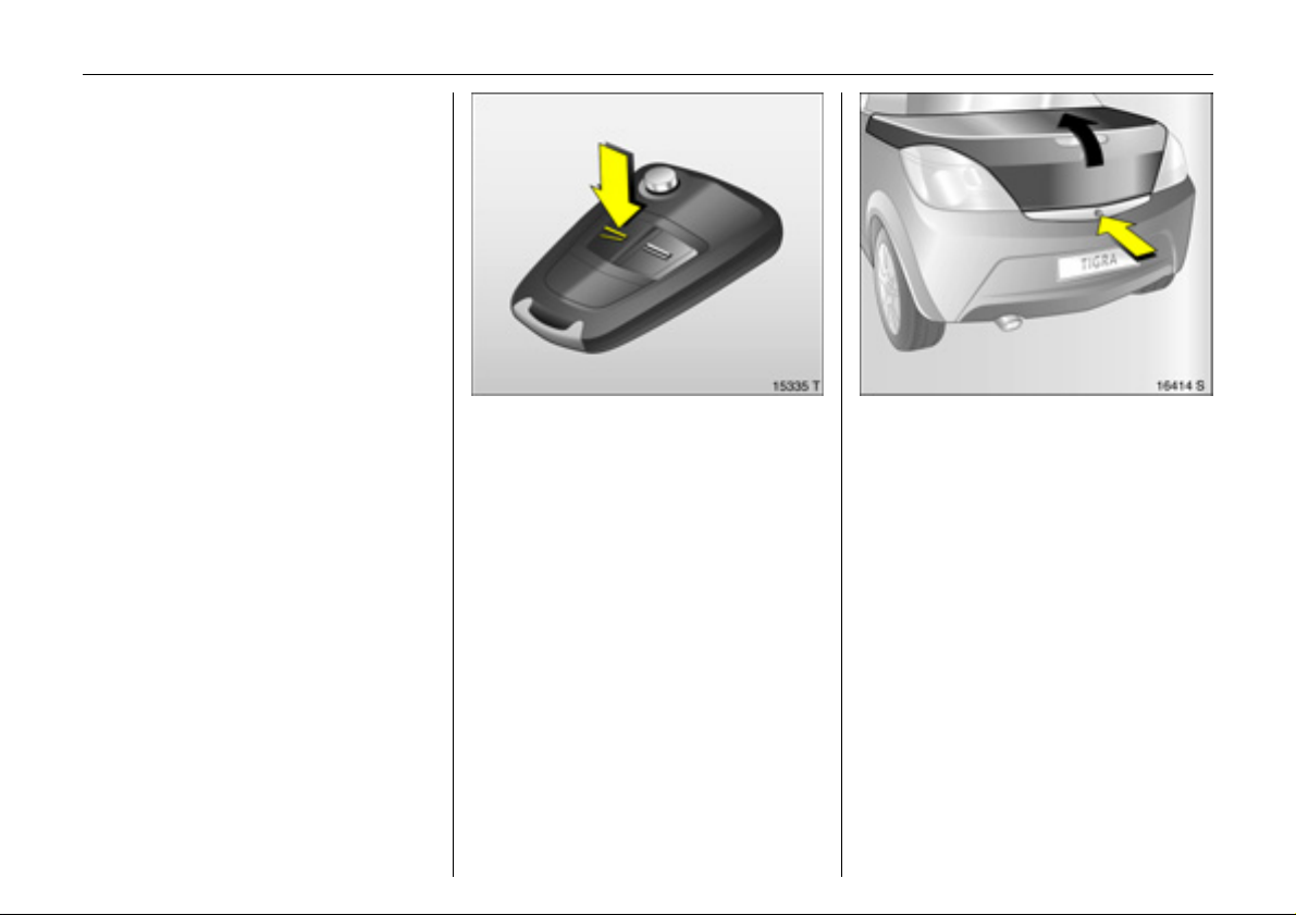
To unlock and open luggage
compartment: Press button q on
remote control twice, press
button beneath the boot lid
To unlock with button in driver’s door
handle: With vehicle unlocked, ignition on
and handbrake applied, briefly pull
button R.
Luggage compartment 3 26,
Remote control 3 3 22.
Page 7
3In Brief
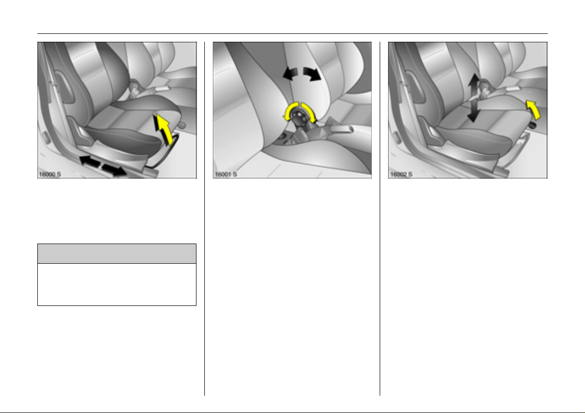
To adjust seat leg room:
Pull handle, slide seat,
release handle
Seats 3 44,
Seat position 3 45.
9 Warning
Important: Do not sit nearer than
10 inches (25 cm) from the steering
wheel, to permit safe airbag
deployment.
To adjust seat backrests:
Turn handwheel
Do not lean on seat backrest whilst
adjusting it.
Seats 3 44,
Seat position 3 45.
Seat cushion height: Pull lever
Lift lever and relieve some weight from seat
to raise it or press down on seat with body
weight to lower it.
Seats 3 44,
Seat position 3 45.
Page 8
4In Brief
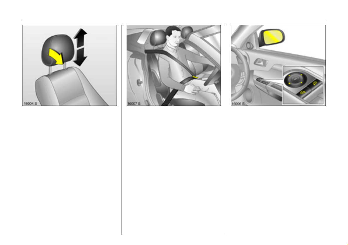
Head restraint height: To release,
tilt head restraint forward, hold
and adjust height, engage
Head restraints 3 46,
Head restraint position 3 47,
Head restraint removal 3 47.
Pull out the seat belt and click
into belt buckle
The seat belt must not be twisted and must
lie snugly against the body. The backrest
must not be tilted back too far (maximum
approx. 25°).
To release belt, press red button on belt
buckle.
Three-point seat belts 3 49,
Airbag system 3 54,
Seat position 3 45.
Adjust exterior mirrors
Select corresponding exterior mirror and
adjust with the four-way switch.
Mirrors 3 31,
Aspherical exterior mirrors 3 31,
Heated exterior mirrors 3 11, 3 32.
Page 9
5In Brief
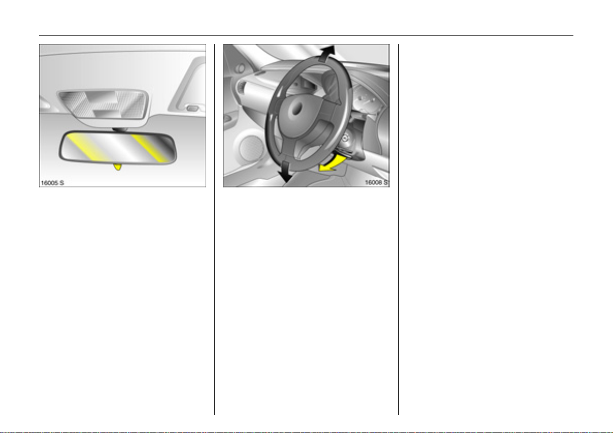
To adjust interior mirror by
swivelling
Swivel lev er on underside of mirror housing
to reduce dazzle.
Interior mirror 3 32.
Steering wheel adjustment 3:
Sw iv el le v e r dow n, ad just hei g h t ,
swivel lever up, engage
Ad jus t stee rin g whe el only when ve hic le is
stationary and steering column lock is
re l ea s e d.
Airba g s yst e m 3 54,
Steering column lock 3 13.
Page 10
6In Brief
Page 11

7In Brief
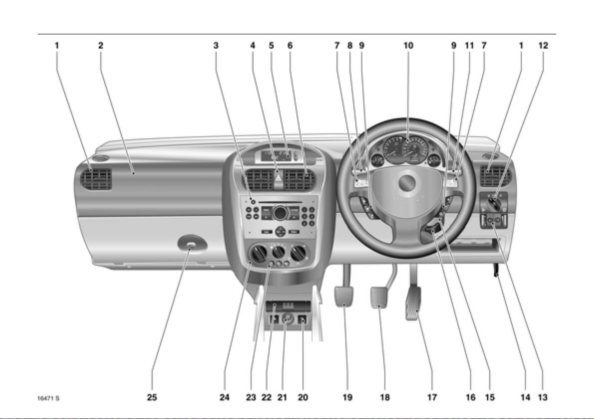
1 Side air vents ............................... 3 92
2 Front passenger airbag .............. 3 54
3 Infotainment system 3 ....... 3 74,3 91
4 Hazard warning lamps ...... 3 10, 3 88
LED for Vauxhall alarm
system 3 .........................................3 30
5 Information display
for time, date,
outside temperature,
Infotainment system 3 ............... 3 74
Trip computer 3 .......................... 3 81
6 Centre air vents .............................3 92
7 Horn ...............................................3 10
Driver’s airbag ............................. 3 54
8 Turn signal lamps ................ 3 9, 3 87
Headlamp flash ................... 3 9, 3 87
Dipped beam,
Main beam ........................... 3 9, 3 87
Door-to-door lighting 3 ...............3 88
Cruise control 3 ..........................3 116
9 Remote control on steering
wheel 3...........................................3 90
10 Instruments........................... 3 66,3 72
11 Windscreen wipers ............. 3 10, 3 85
Windscreen washer
system ..................................
12 Parking lamps,
dipped beam ........................ 3 9, 3 86
13 Headlamp range adjustment ......3 88
Fog tail lamp .................................3 87
Front fog lamps 3 .........................3 87
Instrument illumination ................3 89
14 Bonnet release lever ................... 3 126
3 11, 3 85
15 Ignition switch
with steering column lock ........... 3 13
16 Steering wheel adjustment 3 ....... 3 5
17 Accelerator pedal .......... 3 106, 3 108
18 Brake pedal .......... 3 70, 3 106, 3 119
19 Clutch pedal 3 ........................... 3 106
20 Heated seats 3 ............................ 3 46
21 Accessory socket or
cigarette lighter ........................... 3 63
22 Ashtray 3 ...................................... 3 64
23 Air conditioning system 3 ........... 3 96
Heated rear window ........... 3 11, 3 34
Air recirculation system 3............ 3 97
24 Climate control ............................ 3 92
25 Glove compartment ....................
3 65
Page 12

8In Brief
Control indicators
X
>
A
Z
v
Seat belt 3,
3 66, 3 49.
Front fog lamps 3,
3 66, 3 87.
Engine electronics,
Immobiliser 3, Easytronic 3,
Fault,
3 21, 3 67, 3 104, 3 112.
Exhaust emission 3,
3 67, 3 112.
Airbag systems, Belt tensioners,
3 50, 3 58.
I
O
C
!
j
T
r
Engine oil pressure,
3 68.
Turn signal lamps,
3 9, 3 69, 3 87.
Main beam,
3 9, 3 69, 3 87.
Preheating for diesel engines 3,
3 69.
Easytronic 3, Start engine 3,
3 69, 3 101.
Easytronic 3,
Winter programme,
3 103.
Fog tail lamp,
3 69, 3 87.
p
R
u
S
EPS
v
Y
y
Alternator,
3 69.
Brake system, clutch system,
3 70, 3 164.
Anti-lock Braking System
(ABS) 3,
3 120.
Engine oil level 3,
3 70, 3 160.
Electric Power-assisted Steering
(EPS) 3,
3 70.
Electronic Stability Programme
Plus
(ESP®
3 71, 3 114.
Fuel level,
3 71, 3 111.
Seat occupancy recognition 3,
3 71, 3 59.
) 3,
Page 13
9In Brief
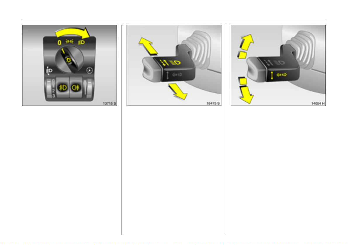
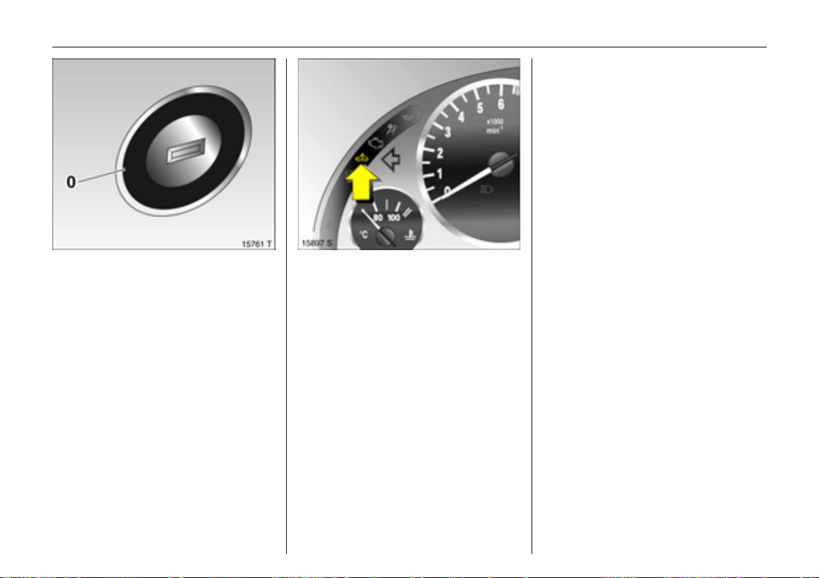
Exterior lights
Turn
7 =Off
8 = Parking lamps
9 = Dipped beam or main beam
Press
> = Front fog lamps 3
r = Fog tail lamp
0 =Courtesy lamp
Lighting 3 86,
Headlamp warning buzzer 3 14, 3 84.
Headlamp flash, main beam and
dipped beam
Headlamp flash = Pull stalk towards
steering wheel
Main beam = Push stalk forwards
Dipped beam = Push stalk forwards
again
Main beam, headlamp flash 3 87.
Switch on turn signal lamps
Right = Stalk up
Left = Stalk down
Turn signal lamps 3 87.
Page 14
10 In Brief
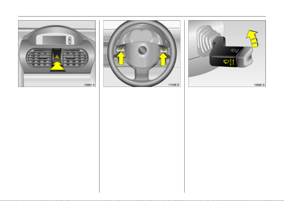
Hazard warning lamps
Operated with the ¨ button.
Hazard warning lamps 3 88.
Horn j: press right or left
Airbag system 3 54,
Remote control on steering wheel 3 3 90.
Windscreen wipers
& =Fast
% =Slow
$ = Adjustable timed interval wipe
§ =Off
Windscreen wipers 3 85,
Adjustable wiper interval 3 3 85,
Change windscreen wipers 3 165.
Page 15
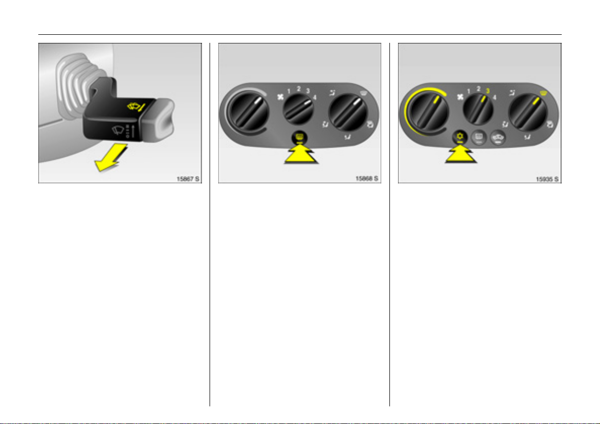
11In Brief
Operating windscreen washer
system: Pull stalk toward steering
wheel
The wipers will swipe for a few strokes.
Windscreen washer system 3 85,
further information 3 165.
Heated rear window, heated
exterior mirrors
Operated with the Ü button.
Climate control system 3 3 92,
Heated rear window 3 34.
To clear fogged or icy windows
Rotary knob for temperature and air flow
clockwise, air distribution to V,
Air conditioning system 3: also press
button n.
Climate control system 3 3 92.
Page 16
12 In Brief
Before starting off, check
z Tyre pressure and tyre condition 3 121,
3 176.
z Engine oil level and fluid levels 3 159
to 3 165.
z All windows, mirrors, exterior lighting
and number plates are free from dirt,
snow and ice and operational.
z Seats, seat belts and mirrors are
correctly adjusted. 3 44, 3 49, 3 31
z Check brake function at low speed,
particularly if the brakes are wet.
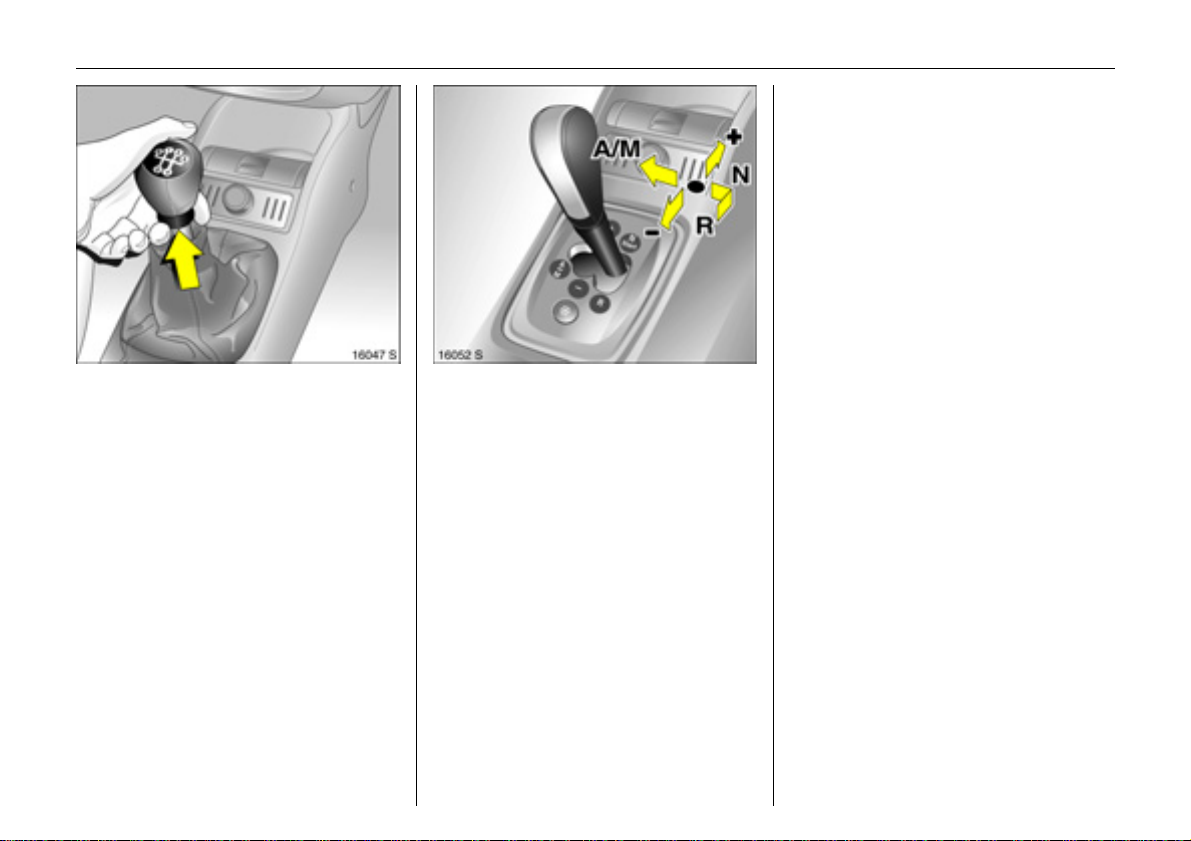
Manual transmission
Reverse: With the vehicle stationary,
depress the clutch pedal, wait 3 seconds,
then raise ring under gearshift lever and
engage gear.
If the gear does not engage, set the lever
in neutral, release the clutch pedal and
depress again; then repeat gear selection.
Manual transmission 3 105.
Easytronic 3
N = Neutral/idle/start position
o = Driving position
+ =Higher gear
- = Lower gear
A/M = Switch between Automatic and
Manual mode.
R = Reverse gear
(with selector lever lock)
To move the selector lever from N to R
press the button on the lever.
Only start in N with footbrake depressed.
Easytronic 3 3 100.
Page 17
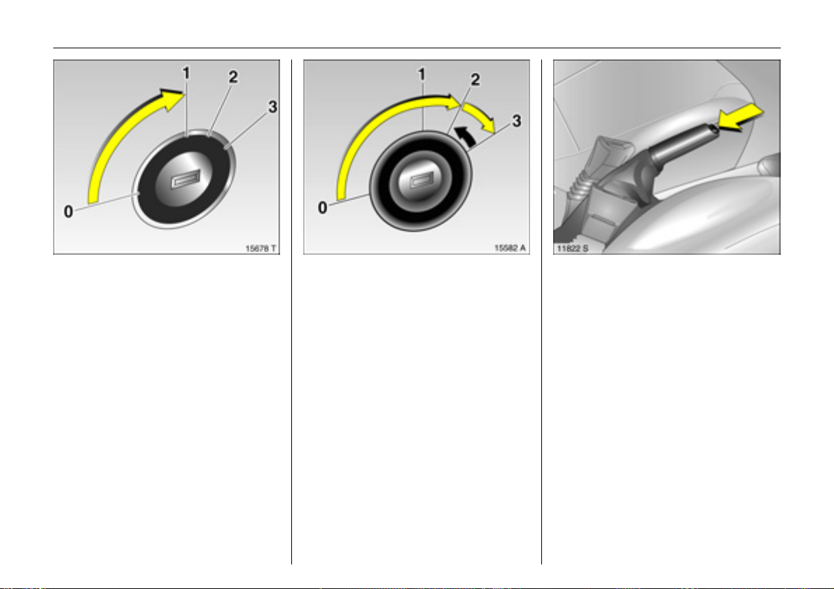
13In Brief
Steering column lock and ignition
Turn key to position 1. Move the steering
wheel slightly to release the steering
column lock.
0 =Ignition off
1 = Steering free, ignition off
2 = Ignition on, for diesel engine:
preheating
3 =Starting
Starting the engine
Depress the clutch and brake pedals,
Easytronic 3 in N, do not press accelerator,
for diesel engine: turn key to 2 until control
indicator ! goes out, turn key to 3; release
key when engine is running.
Before restarting or switching off the
engine, turn key back to 0.
To switch on the ignition, only turn the key
to 2.
Releasing the handbrake:
Raise lever slightly, Press release
button, Lower lever fully
Handbrake 3 121.
Page 18

14 In Brief
Parking the vehicle
z Always apply handbrake without
pressing release button. Apply as firmly
as possible on a downhill slope or uphill
slope. Operate footbrake at same time
to reduce operating force.
z Switch off engine and ignition. To do this,
turn ignition key to 0 and remove. Turn
steering wheel until steering column lock
perceptibly engages (anti-theft
protection).
On vehicles with Easytronic 3, control
indicator R flashes for a few seconds
after the ignition is switched off if the
handbrake has not been applied.
z If the vehicle is on a level surface or uphill
slope, engage first gear before switching
off the ignition. On an uphill slope, turn
the front wheels away from the kerb.
If the vehicle is on a downhill slope,
engage reverse gear before switching off
the ignition. Turn the front wheels
towards the kerb.
z Lock vehicle and arm Vauxhall alarm
system 3 with button p on the remote
control.
To activate the anti-theft locking
system 3, press button p twice.
Advice when parking
z Do not park the vehicle on flammable
ground as combustion could occur due
to the high exhaust temperatures.
z Close windows and retractable steel
roof.
z The engine cooling fans may run after
the engine has been switched off, 3 159.
z After running at high engine speeds or
with high engine loads, operate the
engine briefly at a low load or run in
neutral for approx. 30 seconds before
switching off in order to protect the
turbocharger 3.
Remote control 3 3 22,
Central locking system 3 23,
Vauxhall alarm system 3 3 29,
Laying the vehicle up for a long period
3 166.
Page 19
Interesting functions
15In Brief
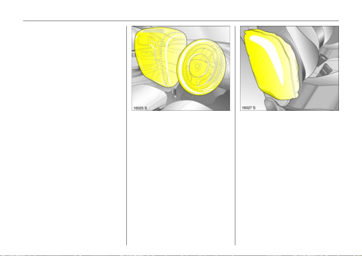
Airbag system
The airbag system consists of several
separate systems.
Front airbag system
The front airbag system will be triggered in
the event of a serious accident involving a
frontal impact and forms safety cushions
for the driver and front passenger. The
forward movement of the driver and front
passenger is checked and the risk of
injuries to the upper body and head
thereby substantially reduced.
Side airbag system
The side airbag is triggered in the event of
a side-on collision to form a safety cushion
for the driver or front passenger in the
respective door area. This substantially
reduces the risk of injury to the upper body
and pelvis.
Airbag system 3 54.
Page 20
16 In Brief
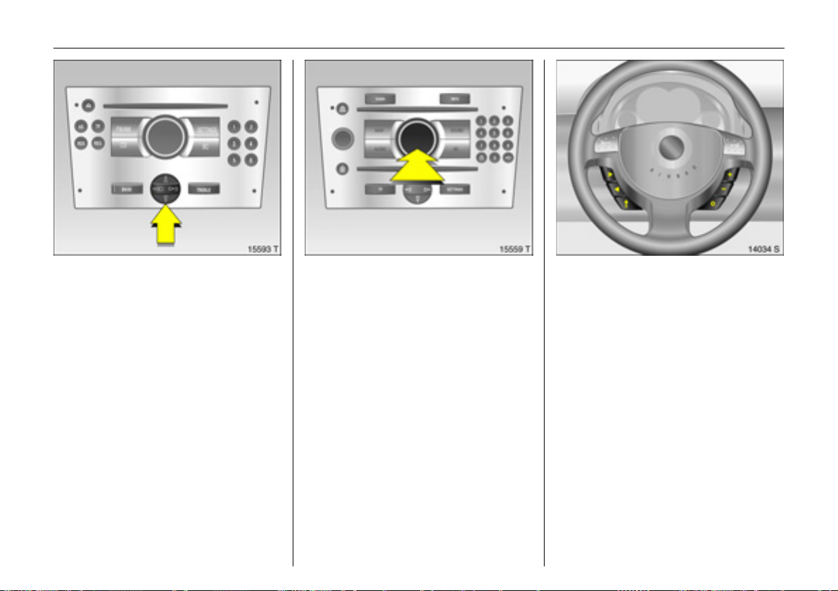
Operating menus in the
information display 3
Menu options are selected using menus
and using the buttons/four-way button or
the multifunction knob of the Infotainment
system 3 or the buttons 3 on the steering
wheel. The respective menu options are
shown on the display.
Selection using four-way button: press
four-way button at top, bottom, left or
right.
Selection using multifunction knob 3:
rotate and press multifunction knob.
To exit a menu, turn the multifunction knob
left or right to Return or Main and select.
To select with steering wheel buttons 3
Select menu options via the menus and the
buttons.
Information display 3 74.
Page 21
Ü Board Computer 19,5° 19:36
BC 1 All values
BC 2
Timer
1111
257.0 miles
Ø40mph
7.0 gal
8888
Ø 48.0 miles/gal
17In Brief
Trip computer 3
Functions:
z Range
z Instantaneous consumption
z Distance travelled
z Average speed
z Effective consumption
z Average consumption
z Stop watch
Trip computer 3 81.
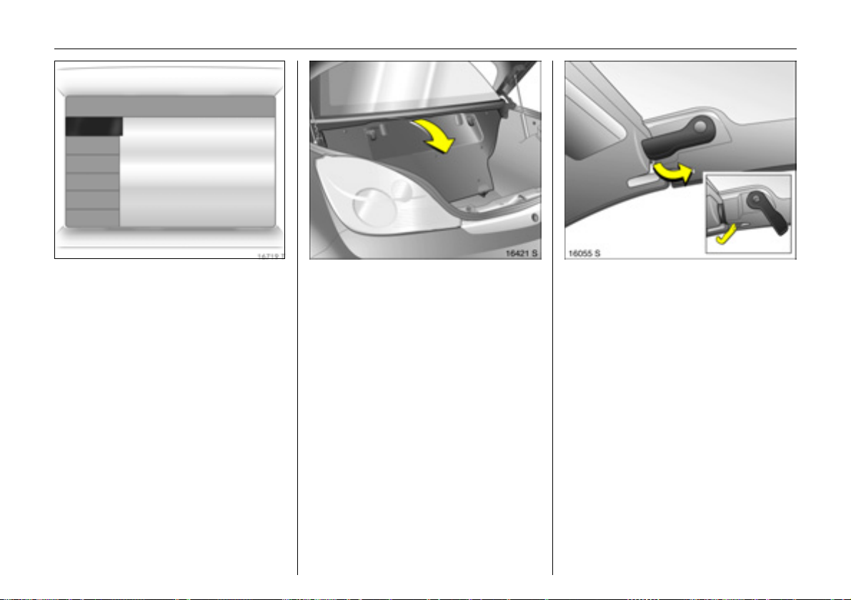
Opening retractable steel roof
Only with vehicle stationary.
z Apply handbrake
z Engage the luggage compartment
partition in the rear position.
z Place no objects in front of the rear
window or in front of the luggage
compartment partition.
z Close the boot lid.
z Release the locking levers on upper
right and left of the window frames,
pulling both levers all the way down.
The retaining hook must unhook.
Page 22
18 In Brief
Closing retractable steel roof
Only with vehicle stationary and boot lid
closed.
The luggage compartment partition must
be engaged in its rear position. Do not
place any objects in front of the luggage
compartment partition.
z Apply handbrake
z Switch on ignition.
z Switch on ignition.
z Pull S until the roof is completely open
and the boot lid is closed.
An acoustic signal sounds at the
beginning and end of the procedure.
If the handbrake is not applied, the roof
lock is not released or the luggage
compartment partition is not folded
back when button S is actuated, a
warning buzzer sounds and the roof
does not open.
Retractable steel roof 3 34.
z Press S until the roof and boot lid are
completely closed.
An acoustic signal sounds at the
beginning and end of the procedure.
If button S is actuated when the
handbrake is not applied, a warning
buzzer sounds and the roof remains
open.
Page 23
19In Brief
z Move the locking levers on right and left
of the window frames all the way up.
Each retaining hook must engage and
the roof must lock securely.
Retractable steel roof 3 34.
Ultrasonic parking sensors 3
When reverse gear is selected, the parking
distance sensors switch on automatically.
An acoustic warning sounds when the
vehicle approaches an obstacle behind it.
6 Ultrasonic parking sensors 3 3 118.
Page 24
20 Keys, Doors, Windows, Retractable Steel Roof
Keys, Doors, Windows,
Retractable Steel Roof
Replacement keys ............................... 20
Lock cylinders ...................................... 20
Key with retractable key blade 3 ...... 20
Car Pass................................................ 20
Electronic immobiliser.......................... 21
Remote control 3................................. 22
Central locking system ........................ 23
Operating central locking system with
key in driver’s door lock.................... 25
Luggage compartment....................... 26
Vauxhall alarm system 3.................... 29
Exterior mirrors..................................... 31
Interior mirror ....................................... 32
Electric windows................................... 32
Retractable steel roof.......................... 34
Wind deflector 3.................................. 43
Replacement keys
The key number is specified in the
Car Pass 3.
The key is part of the electronic
immobiliser.
Locks 3 151.
Lock cylinders
Designed to free-wheel if they are
forcefully rotated without the correct key or
if the correct key is not fully inserted.
To reset, turn cylinder with the correct key
until its slot is vertical, remove key and then
re-insert it. If the cylinder still free-wheels,
turn the key through 180° and repeat
operation.
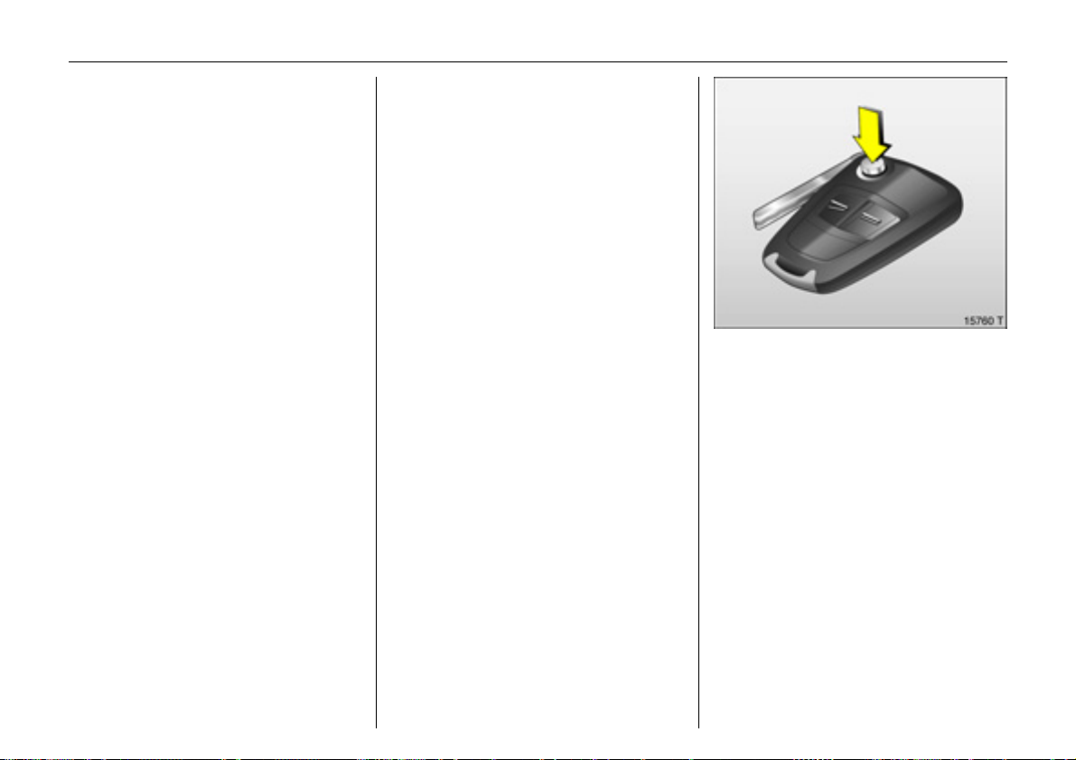
Key with retractable key blade 3
Press button to extend. Press button to
retract; key section engages audibly.
Car Pass
The Car Pass contains safety-related
vehicle data and should therefore be kept
in a safe place.
When the vehicle is taken to a workshop,
the Car Pass data is needed in order to
perform certain operations.
Page 25
21Keys, Doors, Windows, Retractable Steel Roof
If control indicator A illuminates after
the engine has started, there is a fault
in the engine electronics or transmission
electronics 3 3 67, 3 104, 3 112 or there
is water in the diesel fuel filter 3 3 162.
Note
The immobiliser does not lock the doors.
You should always lock the vehicle after
leaving it and switch on the Vauxhall alarm
system 3, 3 23.
Electronic immobiliser
The system checks whether the vehicle is
allowed to start with the key used. Once
the transponder in the key is recognised,
the vehicle can be started.
The electronic immobiliser activates
automatically when the key is removed
from the ignition switch.
Control indicator for immobiliser A
Control indicator A illuminates briefly
when the ignition is switched on.
If the control indicator flashes when the
ignition is on, there is a fault in the system;
the engine cannot be started. Switch off
the ignition and then repeat the start
attempt.
If the control indicator A continues to
flash, try to start the engine using the
second key and contact a workshop for
assistance.
Page 26
22 Keys, Doors, Windows, Retractable Steel Roof
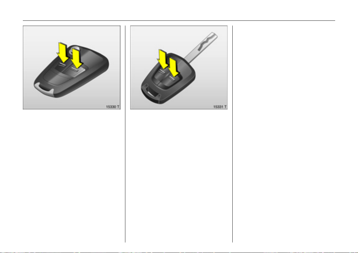
Remote control 3
Depending on equipment level, the vehicle
comes equipped with one of the remote
controls depicted on this page.
The remote control is integrated in the key.
Used to operate:
z central locking system,
z mechanical anti-theft locking system 3,
z Vauxhall alarm system 3.
The windows can also be closed using the
remote control.
The remote control has a range of approx.
5 metres. This range can be affected by
outside influences. Aim the remote control
at the vehicle to operate. The hazard
warning lamps flash to confirm remote
control operation.
Handle the remote control with care,
protect it from moisture and high
temperatures and avoid unnecessary
operation.
Fault
If the central locking system cannot be
operated with the remote control, it may
be due to the following:
z Range exceeded.
z Battery voltage in remote control too
low, change battery.
z Frequent successive activations of the
remote control outside the range of
the vehicle (this means that the remote
control is no longer recognized).
Synchronise remote control.
z If the central locking system is
overloaded as a result of repeated
operation at short intervals. The power
supply is cut off for a brief period.
z Interference from higher-power radio
waves from other sources.
Opening the vehicle 3 25.
Page 27
23Keys, Doors, Windows, Retractable Steel Roof
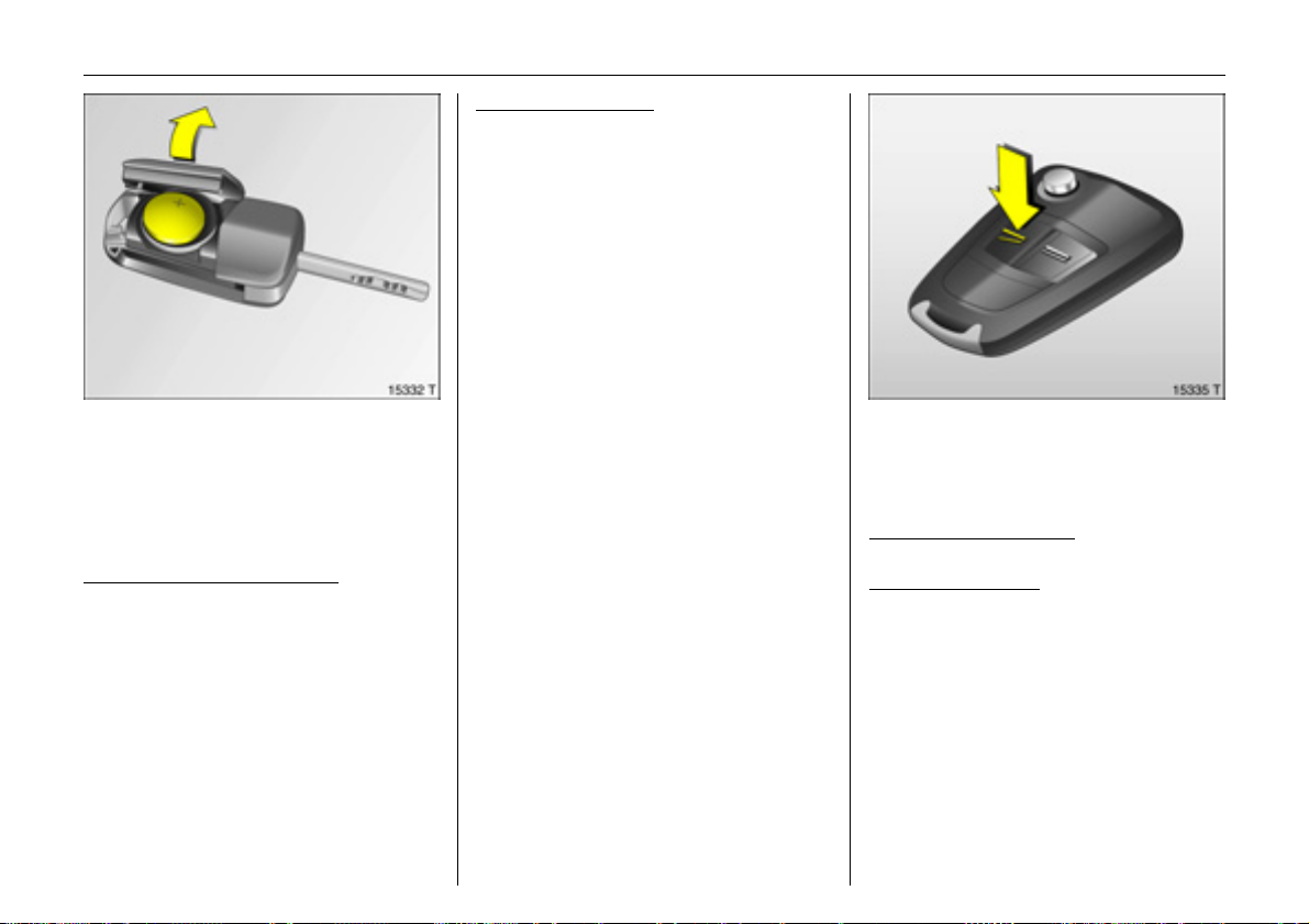
Remote control battery replacement
Replace the battery as soon as the range
of the remote control begins to shrink.
Batteries do not belong in household
waste. They must be disposed of at an
appropriate recycling collection point.
Key with retractable key blade
see Fig. 15330 T on previous page.
Extend the key 3 20. Open the remote
control. Replace the battery (battery
type CR 20 32), noting installation position.
Close the remote control and synchronise.
,
Key with fixed key bit
see Fig. 15331 T on previous page.
Have the workshop change the battery.
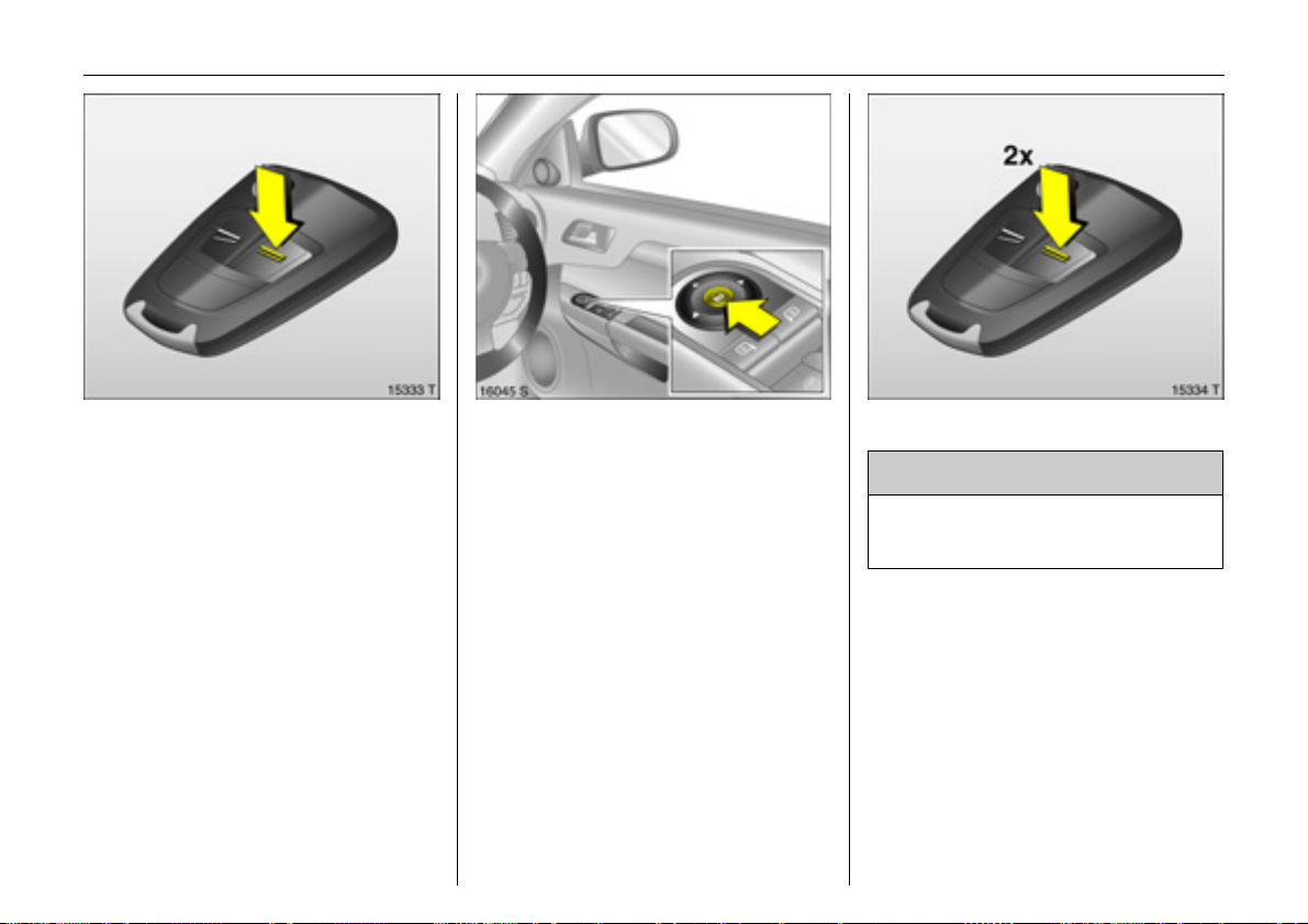
Remote control synchronisation
After changing the battery, unlock the
door using the key. Insert the key in the
ignition lock to synchronise the remote
control.
,
Central locking system
Used to unlock and lock doors, luggage
compartment cover and tank flap.
To unlock
Unlock driver’s door only
Press button q on remote control once.
Unlock entire
Press button q on remote control twice.
The vehicle can also be unlocked by pulling
the door handles if the anti-theft locking
system is disabled.
vehicle
Page 28
24 Keys, Doors, Windows, Retractable Steel Roof
To lock
Close doors, luggage compartment and
tank flap.
Press button p on remote control.
– or from the inside –
Press button m in the door.
The vehicle can be locked even if the
driver’s door is open. Risk of being locked
out.
Mechanical anti-theft locking system 3
9 Warning
Do not use the system if there are people
in the vehicle! The doors cannot be
unlocked from the inside.
All doors must be closed.
If the ignition was on, the driver’s door
must be opened and closed once so that
the vehicle can be secured.
All doors are secured against opening.
Page 29
25Keys, Doors, Windows, Retractable Steel Roof
Within 10 seconds of locking, press the p
button on the remote control again.
Unlocking the vehicle switches off the
mechanical anti-theft locking system.
Note
z A short time after unlocking using the
remote control the doors lock again
automatically if no door is opened.
z To lock the doors from inside (e.g. to
prevent unwanted entry from outside),
press central locking switch m in the
door trim.
z The vehicle can be locked without the
need for the key. With the driver’s door
open, press central locking switch m in
the door trim and then close the driver’s
door. Note that unintentional actuation
could cause one to be locked out.
z Locked doors and luggage
compartment unlock automatically in
the event of an accident of a certain
severity (to permit outside assistance).
Prerequisite: Ignition must not be
switched off.
Fault
If the central locking cannot be operated,
this can be for one of the following reasons:
z If the central locking system is
overloaded as a result of repeated
operation at short intervals. The power
supply is cut off for a brief period.
z Faulty fuse in fuse box 3 140.
To eliminate the cause of the fault, contact
a workshop.
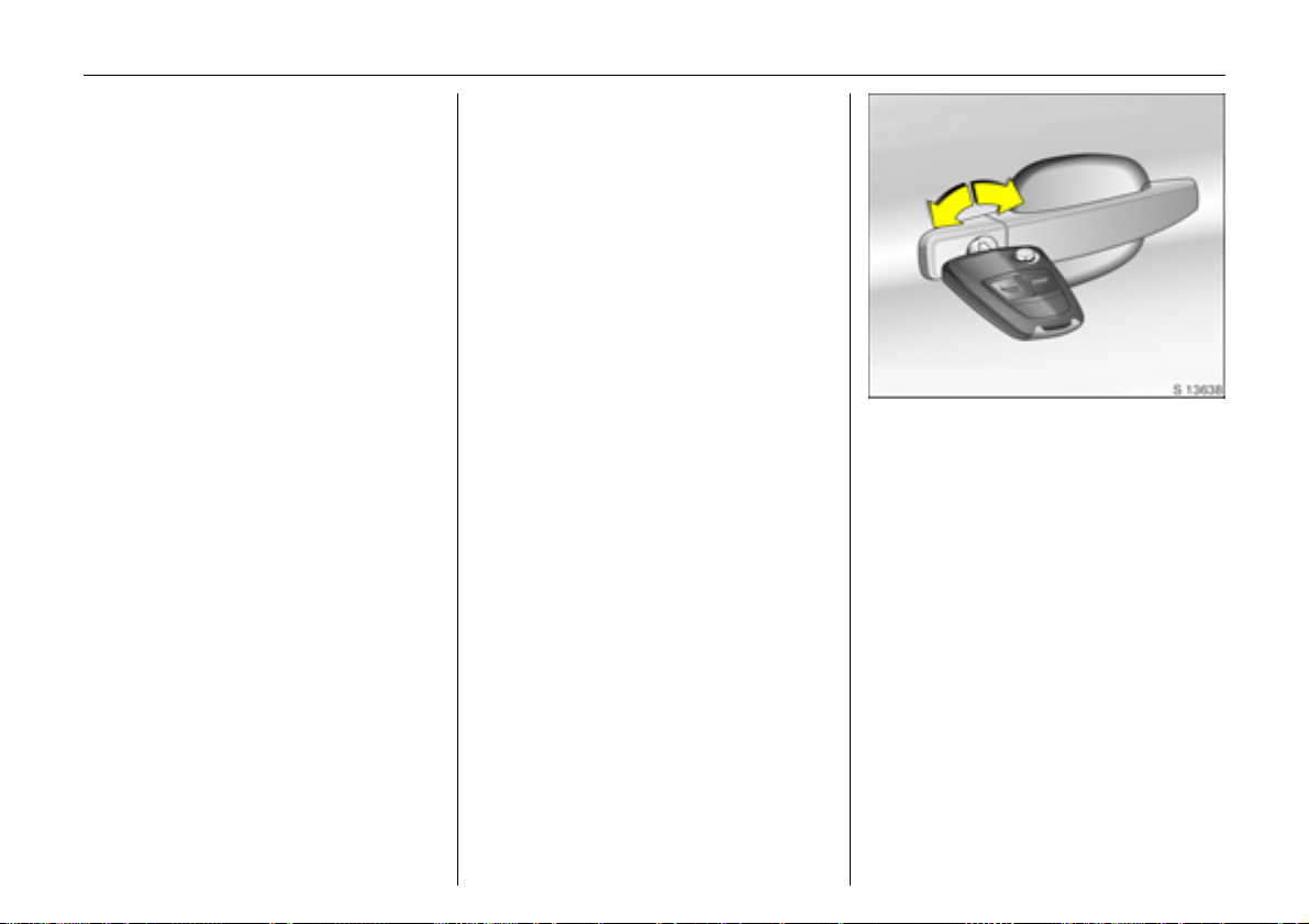
Use the key to open and close the driver’s
door.
Operating central locking system
with key in driver’s door lock
To unlock
Turn key forward in lock as far as it will go.
Turn back to vertical position and remove.
If the anti-theft locking system 3 is
engaged, only the driver’s door will unlock.
To unlock the entire vehicle: switch on the
ignition, press central locking switch m and
pull the driver’s door handle.
To lock
With doors closed, turn key towards rear of
vehicle as far as it will go. Turn back to
vertical position and remove.
Page 30
26 Keys, Doors, Windows, Retractable Steel Roof
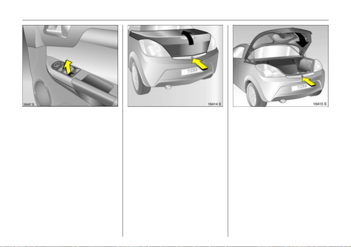
Luggage compartment
To open with the button in the driver’s
door handle
1. Unlock entire vehicle 3 23.
2. Apply handbrake.
3. Switch on ignition.
4. Briefly press button R. The opening
process begins after a slight delay.
Pressing the button again stops the
opening process.
If the handbrake is not engaged when the
button is pressed, a warning buzzer sounds
and the luggage compartment remains
closed.
To open with the button beneath the boot
lid
1. Unlock entire vehicle 3 23.
2. Briefly press the button beneath the boot
lid. The opening process begins after a
slight delay.
Pressing the button again stops the
opening process.
If the ignition is on but the handbrake is not
applied when the button is pressed, a
warning buzzer sounds and the luggage
compartment remains closed.
To close:
Press the button below the boot lid until the
lid is completely closed.
If the ignition is on but the handbrake is not
applied when the button is pressed, a
warning buzzer sounds and the luggage
compartment closes.
A tone sounds when the boot lid is
completely closed. Locking of the lid
is indicated by a single flash of the hazard
warning lamps.
Page 31

27Keys, Doors, Windows, Retractable Steel Roof
Fault
The boot lid can only be operated if the
roof has been fully and correctly closed or
opened beforehand.
In the event of automatic drive malfunction
or loss of battery power, the boot lid is
manually opened as follows:
1. Open the door.
2. Fold down the seat backrest. The tool is
fastened underneath the seat.
3. Turn the tool 90° to the right to remove.
4. Pull the front of the tool upward and out
of the flooring.
5. Pull the tool forward out of the flooring.
Page 32

28 Keys, Doors, Windows, Retractable Steel Roof
6. Open and fold down the cover of the
emergency release cable. Pull the cable
out slightly.
7. Insert the tool through the eye of the
emergency release cable. Support the
rounded end of the tool on the cover as
illustrated. The eye of the emergency
release cable must lie in the groove on
the tool.
8. Have a second person hold the rear of
the boot lid down. Pull the tool forward
to release the lid at the rear.
9. Carefully open the boot lid by hand.
Refit the emergency release cable in the
opening and refit the cover. Do not close
the vehicle door if the cover is open.
To close the boot lid, have a second person
help you press it down and engage it in the
lock.
Have the cause of the fault eliminated by a
workshop.
Page 33

Vauxhall alarm system 3
Monitors:
z doors, luggage compartment, bonnet,
z the passenger compartment,
z vehicle tilt e.g. if it is raised,
z the ignition.
To activate
All doors, windows, retractable steel roof,
luggage compartment and bonnet must
be closed. Press button p on the remote
control.
29Keys, Doors, Windows, Retractable Steel Roof
If the ignition was switched on, the driver’s
door must be opened and closed once so
that the anti-theft alarm system can be
switched on.
Activation without monitoring of
passenger compartment and vehicle tilt
e.g. if animals are to be left in the vehicle.
1. The luggage compartment, retractable
steel roof and bonnet must be closed.
2. Press button in front of the courtesy lamp
(with ignition off); LED in the hazard
warning lamp button flashes a
maximum of 10 seconds.
3. Close doors.
4. Activate the anti-theft alarm system. The
LED in the hazard warning lamp button
illuminates. After approx. 10 seconds,
the anti-theft alarm system is activated
without monitoring of the passenger
compartment or vehicle tilt. The LED in
the hazard warning lamp button flashes
until the anti-theft alarm system is
deactivated.
Passenger compartment monitoring is
deactivated if the retractable steel roof is
open to prevent false alarms.
Page 34

30 Keys, Doors, Windows, Retractable Steel Roof
After the first 10 seconds of anti-theft
alarm system activation:
z LED flashes
slowly
z LED comes
on for approx.
1 second
On faults, contact a workshop.
=System switched on,
= Switch-off function.
Light emitting diode (LED)
During the first 10 seconds of anti-theft
alarm system activation:
z LED comes on
z LED flashes
quickly
=Test, switch-on delay,
= Door, luggage
compartment or
bonnet open, or
system fault.
To deactivate
Press button q of the remote control
– or –
Switch on ignition.
In the event of a fault in the remote control,
unlock vehicle with key 3 25.
If the alarm is triggered when the driver’s
door is opened, deactivate the anti-theft
alarm system by switching on the ignition.
Page 35

Note
z Changes to the vehicle interior, such as
the use of seat covers, could impair the
function of passenger compartment
monitoring.
z Switch off passenger compartment
monitoring if the interior of the parked
vehicle is heated.
Alarm
When triggered, the alarm gives off an
acoustic signal (horn) and a visual signal
(hazard warning lamps). The number and
duration of the alarms are stipulated by
legislation.
The alarm can be silenced by pressing a
button of the remote control or by
switching on the ignition. The anti-theft
alarm system is deactivated at the same
time.
Alarm siren with integrated battery 3
The alarm siren monitors the on-board
voltage network and triggers an alarm if
this network is manipulated (e.g. if the
vehicle’s battery is disconnected by
unauthorised persons). The alarm siren has
its own power supply and is therefore not
dependent on the vehicle’s battery.
If the vehicle’s battery is to be
disconnected (e.g. for maintenance work),
the alarm siren must be deactivated as
follows: switch the ignition on then off,
disconnect the vehicle’s battery within
15 seconds.
To switch off alarm siren:
Switch ignition on then off.
Exterior mirrors
Adjust exterior mirrors
Select corresponding exterior mirror and
adjust with the four-way switch.
Aspherical exterior mirror 3
The aspherical exterior mirror reduces the
blind spot. The shape of the mirror makes
objects appear smaller, so allowing the
estimating of the distance of vehicles
following to be only partly possible.
31Keys, Doors, Windows, Retractable Steel Roof
Swinging in exterior mirror
The exterior mirrors can be folded in by
pressing gently on the outer edge of the
housing.
For the safety of pedestrians, the exterior
mirrors will swing out of their normal
mounting position if they are bumped with
sufficient force. Reposition the mirror by
applying slight pressure to the mirror
housing.
Page 36

32 Keys, Doors, Windows, Retractable Steel Roof
Electric windows
9 Warning
Exercise care when operating electric
windows. Risk of injury, especially for
children.
Vehicle passengers should be informed
accordingly.
Keep a close watch on the windows
when closing them. Ensure that nothing
becomes trapped in them as they move.
Ready for operation
Ready for operation when the ignition is on
Heated exterior mirrors 3
Heating is activated or deactivated by
pressing the Ü button when the ignition is
on.
Interior mirror
To adjust, swivel mirror housing.
To reduce dazzle, swivel the lever on the
underside of the mirror housing.
Page 37

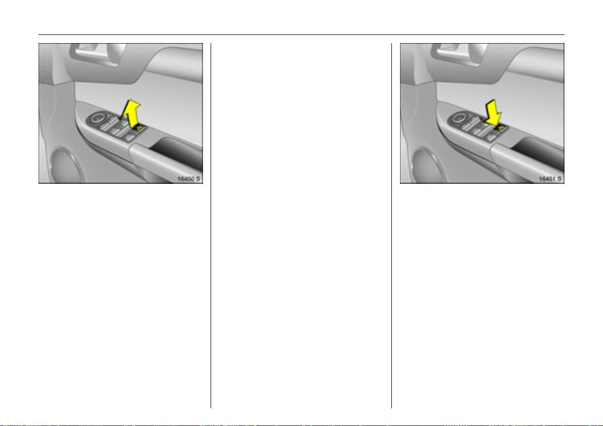
Operation
To operate window in stages, briefly pull or
push relevant window switch. For
automatic opening or closing, pull or push
switch longer; push or pull switch again to
stop movement.
Automatic closing is not possible during
retractable steel roof operation.
When a door is opened, the window of that
door opens slightly. It closes automatically
after the door is closed.
When the retractable steel roof is opened
or closed, the windows open slightly. They
close automatically once the retractable
steel roof is completely opened or closed.
Safety function
If the window glass encounters resistance
above the middle of the window during
automatic closing, it is immediately
stopped and the window opened again.
If the windows do not move easily because
of frost, for example, repeatedly tap the
switch for the window in question until the
window has been closed in stages.
33Keys, Doors, Windows, Retractable Steel Roof
Closing windows from outside
Press button p on the remote control until
the windows are fully closed.
Page 38

34 Keys, Doors, Windows, Retractable Steel Roof
Heated rear window
Heating is activated or deactivated by
pressing the Ü button when the ignition
is on.
Climate control 3 92.
Overload
If the windows are repeatedly operated at
short intervals, the power supply is briefly
cut off.
Fault
If the windows cannot be opened and
closed automatically, activate the window
electronics as follows:
1. Close doors.
2. Switch on ignition.
3. Close the window completely and hold
the button depressed at least 5 seconds
longer.
4. Open the window completely and hold
the button depressed at least 1 second
longer.
5. Repeat for each window.
Retractable steel roof
The retractable steel roof, a foldable steel
top, enables the Tigra to combine the
attributes of a coupe and a convertible.
9 Warning
Exercise care when operating the roof.
Risk of injury.
Pay close attention to the roof’s
movement zone during operation. Make
sure that nothing could become
trapped.
Make sure no one is in the movement
zone during roof operation. Risk of
injury.
Before operating the roof in garages,
parking garages or the like, check the
amount of vertical clearance available.
Vehicle passengers should be informed
accordingly.
Before leaving the vehicle, remove the
ignition key in order to prevent
unauthorised operation of the windows
and sun roof.
Page 39

35Keys, Doors, Windows, Retractable Steel Roof
Opening the roof
Only with vehicle stationary.
Apply handbrake.
Engage the luggage compartment
partition in the rear position.
Place no objects in front of the rear window
or in front of the luggage compartment
partition.
Close the boot lid 3 26.
Release the locking levers on upper right
and left of the window frames, pulling both
levers all the way down. Both retaining
hooks must unhook.
Page 40

36 Keys, Doors, Windows, Retractable Steel Roof
Press S until the roof and boot lid are
completely closed.
An acoustic signal sounds at the beginning
and end of the procedure.
If button S is actuated when the
handbrake is not applied, a warning
buzzer sounds and the roof remains open.
Switch on ignition.
Pull S until the roof is completely open
and the boot lid is closed.
An acoustic signal sounds at the beginning
and end of the procedure.
If the handbrake is not applied, the roof
lock is not released or the luggage
compartment partition is not folded back
when button S is actuated, a warning
buzzer sounds and the roof does not open.
Closing the roof
Only with vehicle stationary and boot lid
closed.
The luggage compartment partition must
be engaged in its rear position. Do not
place any objects in front of the luggage
compartment partition.
Apply handbrake.
Switch on ignition.
Page 41

37Keys, Doors, Windows, Retractable Steel Roof
Push the locking levers on the right and left
side of the window frame all the way up.
The retaining hooks engage in the
corresponding recesses and the roof locks
securely.
Note
z A warning buzzer sounds for 5 seconds
after the handbrake is released and the
vehicle starts off if the roof has not been
properly closed or opened. Remedy this
by stopping the vehicle and repeating
the closing or opening procedure.
z Frequent operation of the roof with the
engine switched off will discharge the
battery.
Fault
Automatic roof operation is only
functional if the roof has been properly
closed or opened beforehand.
Check if:
z the handbrake is applied,
z the ignition is on,
z the luggage compartment partition
is locked in the rear position,
z the boot lid is completely closed,
z the locking levers are unlocked.
If a fault occurs while the roof is opening
or closing, the roof stops in its current
position. A warning buzzer sounds after
2 minutes. After an additional minute,
power to the system is cut-off. The roof
then moves automatically back to the
luggage compartment or toward the
windscreen frame. In order to close
completely, open both windows, remove
the key and carry out the missing steps of
the following description for loss of
automatic drive.
If there is a fault in the automatic drive or
loss of battery power, the fully opened roof
can be manually closed as follows:
1. Park the vehicle and apply the
handbrake.
2. Open both windows or open the doors.
3. Switch off the ignition and remove the
key.
4. Open the luggage compartment. If the
battery has become discharged or there
is a malfunction in the boot lid, the lid
must be opened manually 3 27.
9 Warning
Exercise care when operating the roof.
Risk of injury. Risk of pinching.
Make sure that nothing could become
trapped.
Vehicle passengers should be informed
accordingly.
Closing the roof manually requires
2 persons and the use of great care.
Page 42

38 Keys, Doors, Windows, Retractable Steel Roof
5. Fold down the seat backrest. The tool is
fastened underneath the seat.
6. Turn the tool 90° to the right to remove.
7. Pull the front of the tool upward and out
of the flooring.
8. Pull the tool forward out of the flooring.
Page 43

39Keys, Doors, Windows, Retractable Steel Roof
9. Use the tool to forcefully pull the lock bar
to unlock the cover in front of the rear
window. The lock bar is on the right side
of the vehicle below the cover.
10. With the lock bar pulled, have a helper
pivot the cover upward by hand. The
noise arising from this is normal.
11. Press the button below the boot lid until
the lid is completely closed 3 26.
If this is not possible, force the boot
lid closed again as illustrated; it must
completely engage in the rear lock.
Page 44

40 Keys, Doors, Windows, Retractable Steel Roof
12. Release the front catches of the boot lid
using the tool by inserting the tool in the
guide and pressing the upper end
inward; see illustration above. At the
same time, pull the boot lid slightly
upward out of the catch. Carry out the
procedure on the right and left.
13. With two people working
simultaneously on the right and left,
open the boot lid rearward to its end
position. Do not twist or tilt the boot lid
when doing so.
9 Warning
Luggage compartment does not remain
in open position.
14. Release the roof retainer at the rear left
of the luggage compartment partition
by raising the release lever.
Page 45

41Keys, Doors, Windows, Retractable Steel Roof
15. With the aid of a second person,
carefully and slowly pull the roof
upward. Grip the roof at the sides and
pull forward. Make sure that the boot
lid is completely open.
9 Warning
Caution. Risk of pinching.
16. Pull the roof up to the windscreen
frame.
17. Push the locking levers on the right and
left side of the window frame all the
way up.
The retaining hooks must engage in the
corresponding recess and the roof must
securely lock.
Page 46

42 Keys, Doors, Windows, Retractable Steel Roof
18. Have a second person help to force the
boot lid closed simultaneously on the
right and left. It must engage in the
locks.
Do not twist or tilt the boot lid. The
closed lid is not locked.
19. Next, if possible open and close the
boot lid once using the button below
the lid. The boot lid is then locked.
20. Press down the cover in front of the rear
window.
It is not possible to open the roof if there is
a malfunction in automatic operation.
Have the cause of the fault eliminated by a
workshop.
Page 47

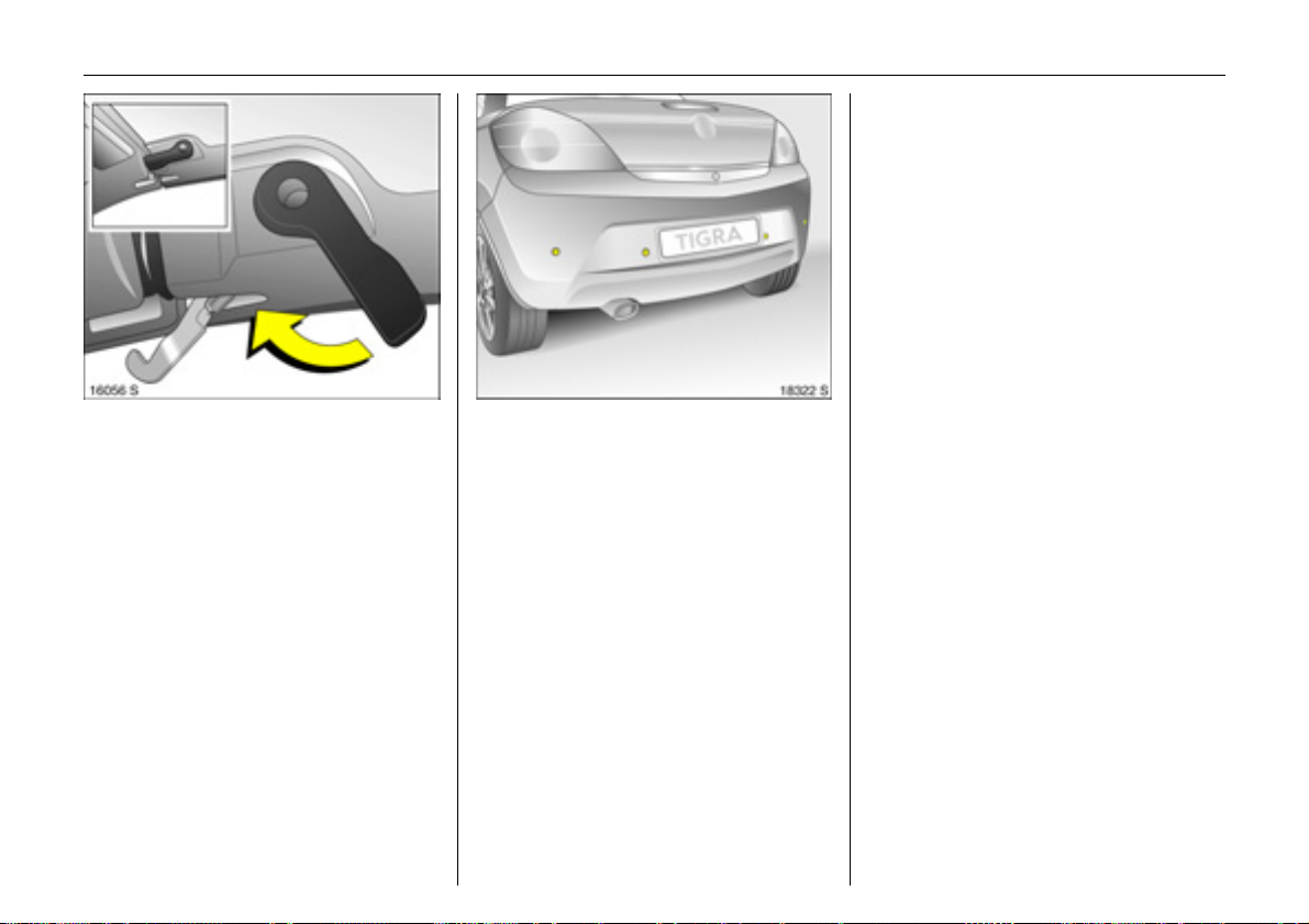
Wind deflector 3
Install the wind deflector to reduce wind
turbulence, draught and noise in the
passenger compartment when the
retractable steel roof is open.
43Keys, Doors, Windows, Retractable Steel Roof
Insert the wind deflector in the opening in
the centre of the rollover protection and
fasten it with the crank.
When removed, store the wind deflector in
the luggage compartment.
Page 48

44 Seats, Interior
Seats, Interior
Front seats ........................................... 44
Head restraints .................................... 46
Luggage compartment partition ....... 47
Three-stage safety system.................. 48
Three-point seat belts ......................... 49
Belt tensioners...................................... 50
Using the belts ..................................... 52
Child restraint systems 3 .................... 53
Airbag system...................................... 54
Cigarette lighter 3............................... 63
Accessory socket 3.............................. 63
Ashtray 3 ............................................. 64
Stowage compartments...................... 64
Coin holder 3 ....................................... 65
Sun visors.............................................. 65
Front seats
9 Warning
Important: Do not sit nearer than
10 inches (25 cm) from the steering
wheel, to permit safe airbag
deployment.
Never adjust seats during driving,
as they can move uncontrollably.
Adjust seat longitudinally
Pull the handle on the front seat, slide the
seat and release the handle.
Adjusting the backrest
Turn side handwheel on the seat while
releasing the pressure on the backrest.
Page 49

45Seats, Interior
Adjusting the seat height
Lift lever and relieve some weight from seat
to raise it or press down on seat with body
weight to lower it.
Fold backrest forward
To fold the back res t fo rwar ds, e .g. to r each
the storage compartment behind the
seats, lift release lever.
Seat position
9 Warning
Only drive with the seat correctly
adjusted.
z Sit with your buttocks as far back against
the backrest as possible. Adjust the
distance between your feet and the
pedals so that your legs are slightly
angled when pressing the pedals.
Slide the passenger seat as far back
as possible.
Page 50

46 Seats, Interior
z Sit with your shoulders as far back
against the backrest as possible. Set
the backrest rake so that you can easily
reach the steering wheel with your arms
slightly bent. Maintain contact between
your shoulders and the backrest when
turning the steering wheel. Do not
angle the backrest too far back.
We recommend a maximum rake
of approx. 25°.
z Adjust the steering wheel 3 5.
z Set seat height 3 high enough to have a
clear field of vision on all sides and of all
display instruments. There should be at
least six inches of clearance between
your head and the headlining. Your
thighs should rest lightly on the seat
without pressing into it.
z Adjust the head restraint.
Heated seats 3
Two pushbuttons ß in the centre console.
For heating with ignition on, press
button ß.
Head restraints
Adjustment
Tilt head restraints forwards, hold and
adjust height. Allow head restraints to
engage after adjustment.
Page 51

47Seats, Interior
Head restraint position
9 Warning
Only drive with the head restraint set to
the proper position.
The middle of the head restraint should be
at eye level. If this is not possible for
extremely tall persons, set to highest
position, and set to lowest position for
small persons.
Removing
Press and release the two catches. Pull and
remove the head restraint.
Stow head restraints securely in luggage
compartment. Do not drive with head
restraints removed if the seat is occupied.
Note
Only approved objects or components
should be attached to the head restraint of
the unoccupied front passenger seat.
Luggage compartment partition
When the retractable steel roof is closed,
the partition can be folded forward to
enlarge the luggage compartment: pull
both catches inward and fold the partition
forward until it engages.
Page 52

48 Seats, Interior
If the retractable steel roof is to be opened,
pull the centre of the partition, release it
and fold it rearward until it engages.
Place no objects in front of the luggage
compartment partition.
Three-stage safety system
Comprising:
z three-point seat belts,
z belt tensioners at the seats,
z airbag systems for driver and front
passenger.
The three stages are activated in sequence
depending on the severity of the accident:
z The automatic seat belt locking devices
prevent the belt strap from being pulled
out and thus ensure that the vehicle
occupants are retained in their seats.
z The seat belts are pulled down at the
belt buckles. This means the belts fit
snugly, the occupants are decelerated
early with the vehicle and the body
loading is reduced.
z The airbag systems are also triggered in
the event of severe accidents and form a
safety cushion for the occupants.
9 Warning
The airbag systems serve to supplement
the three-point seat belts and belt
tensioners. The seat belts must therefore
always be worn. Disregard of these
instructions may lead to injuries or
endanger life. Vehicle passengers
should be informed accordingly.
Always follow the instructions provided
with the child restraint system!
Page 53

Three-point seat belts
The seat belts have an automatic retractor,
so that the belt is spring tensioned and
always lies against the body.
Information on correct seat position 3 45.
The seat belts are locked during heavy
acceleration or deceleration of the vehicle.
This prevents the belt from extending,
keeping the occupant in their seat.
9 Warning
Fasten your seat belt before each trip.
In the event of an accident, persons not
wearing seat belts endanger their fellow
occupants and themselves.
Seat belt control indicator X 3 3 66.
Seat belts are designed to be used by
only one person at a time. They are not
suitable for anyone under 12 years of age
or under 150 cm tall.
For children up to 12 years of age, we
recommend the Vauxhall child restraint
system 3 53.
49Seats, Interior
Testing the seat belts
Check all parts of the belt system
periodically for damage and function.
Replace damaged components. After an
accident, have the seat belts and triggered
belt tensioners replaced by a workshop.
Make sure that seat belts are not damaged
or trapped by sharp-edged objects.
Page 54

50 Seats, Interior
Belt tensioners
The seat belts are pulled down at the
buckles on a front or rear impact above a
certain severity. This tightens the belts.
Actuation of belt tensioners
Indicated by continuous illumination of
control indicator v.
Triggered belt tensioners must be replaced
by a workshop. Belt tensioners can only be
triggered once.
Control indicator v for belt tensioners
The function of the belt tensioners and
airbag systems is monitored electronically
and indicated by the control indicator v.
When the ignition is switched on, the
control indicator illuminates for approx.
4 seconds. If it does not illuminate, or if it
does not go out after 4 seconds, or if it
illuminates whilst driving, there is a fault in
the belt tensioner or airbag systems 3 58.
The systems might not trigger in the event
of an accident.
Deployment of the belt tensioners is
indicated by continuous illumination of v.
Page 55

51Seats, Interior
9 Warning
Have the cause of the fault eliminated
by a workshop immediately.
Self-diagnosis integrated into the system
allows rapid fault identification.
Important
z Do not affix or place accessories or other
objects within the deployment zone of
the belt tensioners. Do not make any
modifications to belt tensioner
components as this will invalidate the
vehicle type approval.
9 Warning
Incorrect handling (e.g. removal or
fitting of seat belts or belt buckles)
can trigger the belt tensioners with risk
of injury.
z The belt tensioner and airbag system
control electronics can be found in the
centre console area. In order to avoid
malfunctions, do not store magnetic
objects in this area.
z We recommend that you have the
front seats removed by a workshop in
the event of triggering of the airbags
and belt tensioners.
z The belt tensioners trigger once only,
indicated by the continuous illumination
of the control indicator v. Have a
workshop replace triggered belt
tensioners.
z When disposing of the vehicle, the
safety instructions given for this must
be observed. Take the vehicle to a
recycling company for disposal.
Page 56

52 Seats, Interior
Using the belts
Fitting seat belts
The seat belt must not be twisted and must
lie snugly against the body. The backrest
must not be tilted back too far (maximum
approx. 25°).
Pull the belt out of the reel, guide it across
the body (making certain it is not twisted)
and engage the latch plate in the buckle.
Tension the lap belt frequently whilst
driving by tugging the shoulder belt.
9 Warning
On pregnant women in particular, the
lap belt must be positioned as low as
possible across the pelvis so as not to
put too much pressure on the abdomen.
Loose or bulky clothing prevents the belt
from fitting snugly. Do not place objects
such as handbags or mobile phones
between the belt and your body.
9 Warning
The belt must not rest against hard or
fragile objects in the pockets of your
clothing.
Removing the belt
To release seat belt, press red button on
belt buckle.
Page 57

53Seats, Interior
Child restraint systems 3
Follow the usage instructions for the child
restraint system.
Always comply with local or national
regulations. In some countries, the use of
child restraint systems is forbidden on
certain seats.
Selecting the right system
Your child should travel facing backwards
in the vehicle for as long as possible. A child
has a very weak cervical spinal column and
in the event of an accident is less likely to
suffer injury in a rearward-facing, semilying position than if seated upright.
9 Warning
Never carry child restraint systems on
your lap, risk of fatal injury.
Permissible options for fitting a child
safety seat
Weight
and
age class
1)
On the front
passenger seat
Group 0: up to 10 kg
or approx. 10 months
Group 0+: up to 13 kg
or approx. 2 years
1
B
Group I: 9 to18 kg
or approx. 8 months
to 4 years
1
B
Group II: 15 to 25 kg
or approx. 3 to 7 years
Group III: 22 to 36 kg
or approx. 6 to 12 years
1
B
B1=Limited,
only with seat occupancy
recognition system and Vauxhall
child restraint system with
transponders 3.
Move seat height 3 to highest
position. Move front passenger seat
back as far as possible.
Note
z Children under 12 years or under 150 cm
tall should only travel in an appropriate
child safety seat.
z When transporting children, use the child
restraint systems suitable for the child’s
weight.
z Check that the child restraint systems
have been correctly installed – see
instructions provided with child restraint
system.
z The covers of Vauxhall child restraint
systems can be wiped clean.
z Do not stick anything on the child
restraint systems and do not cover them
with any other materials.
z A child restraint system which has been
subjected to stress in an accident must
be replaced.
z Secure or remove child restraint systems
carried in the vehicle when not in use.
1)
We recommend the use of each system until
the child reaches the upper weight limit.
Page 58

54 Seats, Interior
Airbag system
Front airbag
The front airbag system consists of one
airbag in the steering wheel and one in the
instrument panel. These can be identified
by the word AIRBAG.
The front airbag system comprises:
z an airbag with inflator in the steering
wheel and a second one behind a trim
panel above the glove compartment,
z the control electronics with impact
sensors,
z control indicator for airbag systems v in
the instrument cluster,
z seat occupancy recognition 3,
z the control indicator for Vauxhall child
restraint systems
in the courtesy lamp.
The front airbag system will be triggered:
z depending on the severity of the
accident,
z depending on the type of impact,
z within the range shown in the illustration,
z independently of the side airbag system.
The ignition must be on.
y with transponders 3
Exception:
Passenger seat with seat occupancy
recognition system 3. The seat occupancy
recognition system deactivates the front
and side airbags for the front passenger
seat if the seat is unoccupied or a Vauxhall
child restraint system with transponders 3
has been fitted to the front passenger seat.
Seat occupancy recognition – 3 58.
Vauxhall child restraint system with
transponders 3 3 59.
Examples of events triggering the front
airbag system:
z Impact against a non-yielding obstacle:
the front airbags are triggered at low
vehicle speed.
z Impact against a yielding obstacle
(such as another vehicle): The front
airbags are only triggered at a higher
vehicle speed.
Page 59

55Seats, Interior
When triggered, the front airbags inflate in
milliseconds and form a safety cushion for
driver and front passenger. Forward
movement is checked and the risk of
injuries to the upper body and head
thereby substantially reduced.
No impairment of view will occur, because
the airbags inflate and deflate so quickly.
9 Warning
Optimum protection is only provided
with the seat in the proper position 3 45.
Keep the area in which the airbag
inflates clear of obstructions.
Wear the three-point seat belt properly
fastened. The front airbag system is
an additional safety device, not a
replacement for your seat belt.
The front airbag system will not be
triggered in the event of:
z the ignition being switched off,
z minor frontal collisions,
z accidents in which the vehicle overturns,
z collisions involving a side or rear impact,
that is to say, if it would not be of benefit
to the occupants.
Page 60

56 Seats, Interior
In addition, the front airbag system
will not be triggered for the front
passenger in versions with seat
occupancy recognition 3 if:
z the front passenger seat is unoccupied,
z there is a properly mounted Vauxhall
child restraint system with
transponders 3 . Seat occupancy
recognition system 3 58. Vauxhall child
restraint system with transponders 3
3 59.
Side airbags
The side airbag system consists of an
airbag in each front seat backrest. This
can be identified by the word AIRBAG.
The side airbag system comprises:
z an airbag with inflator in the back of
the driver’s and front passenger seat
respectively,
z the control electronics,
z the side impact sensors,
z control indicator for airbag systems v in
the instrument cluster,
z seat occupancy recognition 3,
z the control indicator for Vauxhall child
restraint systems
in the courtesy lamp.
y with transponders 3
The side airbag system will be triggered:
z depending on the severity of the
accident,
z depending on the type of impact,
z within the range shown in the illustration
on the driver’s or front passenger side,
z independently of the front airbag
system.
The ignition must be on.
Page 61

Exception:
Passenger seat with seat occupancy
recognition system 3. The seat occupancy
recognition system deactivates the front
and side airbags on the front passenger
seat if the seat is unoccupied or a Vauxhall
child restraint system with transponders 3
has been fitted to the front passenger seat.
Seat occupancy recognition – 3 58.
Vauxhall child restraint system with
transponders 3 3 59.
When deployed, the side airbag inflates
within milliseconds and forms a safety
cushion for the driver or front passenger
in the respective front door area. This
substantially reduces the risk of injury to
the upper body and pelvis in the event
of a side-on collision.
57Seats, Interior
9 Warning
Keep the area in which the airbag
inflates clear of obstructions.
The side airbags will not be triggered in the
event of:
z the ignition being switched off,
z frontal collisions,
z accidents in which the vehicle overturns,
z collisions involving a rear impact,
z collisions involving a side impact outside
the passenger cell.
In addition, the side airbag system will not
be triggered for the front passenger in
versions with seat occupancy recognition 3
if:
z the front passenger seat is unoccupied,
z there is a properly mounted Vauxhall
child restraint system with
transponders 3 . Seat occupancy
recognition 3 58. Vauxhall child restraint
system with transponders 3 3 59.
Page 62

58 Seats, Interior
Control indicator v for airbag systems
The function of the airbag systems is
monitored electronically together with the
seat occupancy recognition 3 and the belt
tensioners, and indicated by the control
indicator v . When the ignition is switched
on, the control indicator illuminates for
approx. 4 seconds. If it does not illuminate,
does not go out after 4 seconds or
illuminates whilst driving, there is a fault in
the airbag systems, seat occupancy
recognition 3 or in belt tensioners 3 50.
The systems may fail to trigger in the
event of an accident.
Deployment of the airbags is indicated by
continuous illumination of v.
9 Warning
Have the cause of the fault eliminated
by a workshop immediately.
Self-diagnosis integrated into the system
allows rapid fault identification.
Seat occupancy recognition 3
The seat occupancy recognition system
deactivates the passenger front and side
airbags if the front passenger seat is
unoccupied or a Vauxhall child restraint
system with transponders 3 has been
fitted to the front passenger seat.
Control indicator
recognition is located in the courtesy lamp.
If control indicator
approx. 4 seconds when the ignition is
switched on, the vehicle is equipped
with seat occupancy recognition 3 58,
Fig. 12097 S.
If a Vauxhall child restraint system with
transponders 3 is fitted, the control
indicator
the ignition is switched on as soon as the
system has detected the child restraint
system. Only then may the child restraint
system with transponders 3 be used on
the passenger seat.
y illuminates permanently after
y for seat occupancy
y illuminates for
Page 63

Vehicles with seat occupancy recognition
can also be identified from the sticker on
the passenger seat.
Vauxhall child restraint systems with
transponders 3 are automatically
detected if correctly fitted to the front
passenger seat. The front and side airbag
systems for the front passenger seat are
deactivated when these child restraint
systems are used. It is essential to observe
the seat occupancy recognition 3 control
indicator 3 58.
9 Warning
Only Vauxhall child restraint systems
with transponders 3 should be fitted on
the front passenger seats. Use of
systems without transponders poses a
risk of fatal injury.
Vauxhall child restraint systems with
transponders 3 can be identified by a
sticker or badge.
Control indicator
restraint systems with transponders 3
The presence of a Vauxhall child restraint
system with transponders 3 is indicated
after the ignition has been switched on by
continuous illumination of the control
indicator
as the seat occupancy recognition system
has detected the child restraint system.
y in the courtesy lamp, as soon
y for Vauxhall child
59Seats, Interior
If the control indicator does not illuminate
during driving, the front and side airbags
for the front seat passenger are not deactivated and there is a risk of fatal injury
to the child. Have a workshop eliminate the
cause of the fault.
If the child restraint system is not correctly
installed or the transponders are defective,
the turn signal lamp will flash. Check for
correct child restraint system installation.
For installation of child restraint system
with transponders 3 – see instructions
provided with child restraint system.
Page 64

60 Seats, Interior
If the control indicator flashes when the
child restraint system with transponders 3
is correctly fitted, there is a fault and a
danger to the child. Have the cause of
the fault eliminated by a workshop.
If no Vauxhall child restraint system with
transponders 3 is fitted, the control
indicator must not illuminate or flash as the
passenger airbag systems would not
deploy. Have the cause of the fault
eliminated by a workshop.
9 Warning
If the Vauxhall child restraint system
with transponders 3 has been fitted
according to the instructions, the control
indicator for Vauxhall restraint systems
with transponders must illuminate in the
courtesy lamp when the ignition is
switched on.
If the control indicator does not
illuminate during driving, the front
passenger airbag systems are not deactivated and there is a risk of fatal
injury. Have a workshop eliminate the
cause of the fault.
Important
z Owing to the risk of injury when the
airbags deploy, accessories and objects
must not be placed within the expansion
range of the airbag systems.
z Do not place any objects between the
airbag systems and the vehicle
occupants; danger of injury.
9 Warning
Never carry child restraint systems or
other objects on your lap - risk of fatal
injury.
z The airbag systems and belt tensioner
control electronics can be found in the
centre console area. In order to avoid
malfunctions, do not store magnetic
objects in this area.
z Do not stick anything on the steering
wheel, instrument panel, seat backrests
or roof frame in the vicinity of the
airbags, or on the front passenger’s seat
cushion, or cover any of those areas with
other materials.
z Use only a dry cloth or interior cleaner
to clean the steering wheel, instrument
panel, seat backrests and seat cushion
of the front passenger seat. Do not use
any aggressive cleaning agents.
z Only protective covers which are
approved for your vehicle with side
airbag may be fitted on the seats. When
fitting the protective covers, make sure
that the airbag units on the outboard
sides of the seat backrests are not
covered.
z The airbag systems are triggered
independently of one another
depending on the severity of the
accident and type of impact.
z Each airbag deploys once only. Have
a workshop replace deployed airbags
immediately.
z The speeds, directions of movement and
deformation properties of the vehicles,
and the properties of the obstacle
concerned, determine the severity of the
accident and triggering of the airbags.
The degree of damage to your vehicle
and the resulting repair costs alone are
not indicative that the criteria for
triggering of the airbags were met.
Page 65

61Seats, Interior
z Do not perform any alterations on the
components of the airbag system, as this
would render the vehicle unroadworthy.
9 Warning
If handled improperly the airbag
systems can be triggered in an explosive
manner – risk of injury!
z We recommend entrusting removal of
the steering wheel, the instrument panel,
all panelling parts and the seats to a
workshop in the event of triggering of the
airbags and belt tensioners.
z When disposing of the vehicle, the safety
instructions given for this must be
observed. Take the vehicle to a recycling
company for disposal.
z In vehicles with seat occupancy
recognition 3 persons weighing less than
35 kg must not be transported. This does
not apply to children that are being
transported in child restraint systems
with transponders 3.
z In vehicles with seat occupancy
recognition 3, do not place any heavy
objects on the front passenger seat
otherwise the airbag systems for the
front passenger seat may be triggered in
the event of an accident.
z In vehicles with seat occupancy
recognition 3, to prevent malfunctions
do not use protective covers or seat
cushions on the front passenger seat.
z When using a Vauxhall child restraint
system with transponders 3 on the front
passenger seat, in order to prevent
malfunctions, no objects (e.g. plastic
sheet, stickers or heated mats) may be
placed under the child restraint system.
9 Warning
Passengers must never carry child
restraint systems and other objects on
their laps. If carried in this way, child
restraint systems with transponders 3
in vehicles with seat occupancy
recognition 3 could prevent the front
passenger airbag systems from being
triggered in the event of an accident.
Page 66

62 Seats, Interior
Use of child restraint systems 3 on the
front passenger seat of vehicles without
seat occupancy recognition 3
9 Warning
No child restraint system 3 may be
installed on front passenger seat.
Danger to life.
Seat occupancy recognition 3 3 58.
Use of a child restraint system 3 on the
front passenger seat of a vehicle with seat
occupancy recognition 3
9 Warning
Only Vauxhall child restraint systems
with transponders 3 can be fitted on the
front passenger seats. Use of systems
without transponders poses a risk of
fatal injury.
Vehicles with seat occupancy recognition
can be identified by control indicator
the courtesy lamp. If control indicator
illuminates for approx. 4 seconds when
the ignition is switched on, the vehicle is
equipped with seat occupancy
recognition 3 58.
Seat occupancy recognition in a vehicle is
also indicated by a sticker on the front
passenger seat – see page Fig. 12106 A.
The seat occupancy recognition system
detects Vauxhall child restraint systems
with transponders 3 and deactivates the
front and side airbags for the front
passenger seat. Seat occupancy
recognition 3 58.
Vauxhall child restraint systems with
transponders 3 can be identified by
a sticker or badge.
y in
y
Page 67

63Seats, Interior
Do not exceed the maximum power
consumption of 120 watts.
Electrical accessories connected to
the socket must comply with the
electromagnetic compatibility
requirements laid down in DIN VDE 40 839,
otherwise vehicle malfunctions may occur.
Do not connect any current-delivering
accessories, e.g. electrical charging
devices or batteries.
Cigarette lighter 3
The cigarette lighter is in the centre
console.
Press in cigarette lighter with ignition
switched on. Switches off automatically
when element is glowing. Withdraw
cigarette lighter.
Accessory socket 3
The accessory socket is in the centre
console.
The accessory socket is ready for use when
the ignition is switched on. Use of the
socket while the engine is not running will
drain the battery.
Caution
Do not damage the sockets by using
unsuitable plugs.
Page 68

64 Seats, Interior
Ashtray 3
Caution
To be used only for ash and not for
combustible rubbish.
Open the ashtray cover to the resistance
point.
To empty, open the ashtray cover fully
beyond its resistance point, causing the
insert to lift. Grip both sides of the ashtray
insert and pull upwards.
To enlarge the storage compartment
remove the ashtray completely.
Stowage compartments
Stowage compartment behind the seats
The compartment is only suitable for
stowing light objects. Maximum load:
10 kg.
9 Warning
Secure objects to prevent them from
falling out and causing injury while
driving.
The load must not hinder pedal,
handbrake or gearshift operation or
impair the driver in any way.
Page 69

65Seats, Interior
Sun visors
Use the sun visor to protect from glare by
pulling it down and swivelling it to the side.
Glove compartment
To open, pull handle upwards.
Can be locked with the vehicle key.
On the inside of the glove compartment
cover there is a pen holder.
The glove compartment should be closed
while the vehicle is in motion.
Coin holder 3
In the centre console.
Page 70

66 Instruments, Controls
Instruments, Controls
Control indicators ................................ 66
Instrument display............................... 72
Information display ............................. 74
Warning buzzers.................................. 84
Windscreen wipers............................... 85
Control indicators
The control indicators described here are
not present in all vehicles. The descriptions
however, apply to all instrument versions.
The control indicator colours mean:
z Red
z Yellow
z Green
z Blue
Danger, important reminder,
Warning, note, fault
On confirmation,
On confirmation,
X
Seat belt 3
Control indicator illuminates red.
Illuminates after turning on the ignition
(with warning tone) until the seat belt is
applied.
Fasten seat belt 3 52.
>
Front fog lamps 3
Control indicator illuminates green.
Illuminates when the front fog lamps are on
3 87.
Page 71

A
Engine electronics, transmission
electronics, immobiliser, diesel fuel filter 3
Control indicator illuminates or flashes
yellow.
It illuminates for a few seconds when the
ignition is switched on.
Illuminate
Fault in engine or transmission electronic
system. Electronics have switched to
the emergency running programme.
Fuel consumption may be increased
and the vehicle’s driveability reduced,
see page 3 112. If the fault cannot be
eliminated by restarting, contact a
workshop immediately.
d when the engine is running
For vehicles with diesel engine, the diesel
fuel filter may need to be drained of water
3 162.
ashes when the ignition is on
If it fl
Fault in the electronic immobiliser system;
the engine cannot be started 3 21.
67Instruments, Controls
Z
Exhaust emission
Control indicator illuminates or flashes
yellow.
It illuminates when the ignition is switched
on and goes out shortly after the engine
starts.
Illuminate
Fault in emission control system. The
permitted emissions may be exceeded.
Contact a workshop immediately.
If it flashes when the engine is running:
Fault that could lead to catalytic converter
damage. Ease up on the accelerator pedal
until the flashing stops 3 112. Seek the
immediate assistance of a workshop.
d when the engine is running
Page 72

68 Instruments, Controls
v
Airbag systems 3, Belt tensioners
Control indicator illuminates red.
Illuminate
Fault in the airbag or belt tensioner
systems 3 50, 3 58.
d when the engine is running
I
Engine oil pressure
Control indicator illuminates red.
Illuminates when the ignition is switched on
and goes out shortly after the engine
starts.
Illuminate
Engine lubrication may be interrupted.
This may result in damage to the engine
and/or locking of the drive wheels.
d when the engine is running
Caution
1. Move out of the flow of traffic as quickly
as possible without impeding other
vehicles.
2. Depress clutch.
3. Move gearshift lever to neutral, or with
Easytronic 3 place selector lever in N.
4. Switch off ignition.
9 Warning
When the engine is off, considerably
more force is needed to brake and steer.
Do not remove key until vehicle has
come to a standstill, otherwise the
steering column lock could engage
unexpectedly.
Check engine oil level before contacting a
workshop.
Page 73

O
Turn signal lamps
Control indicator flashes green.
The control indicator flashes if a turn signal
or the hazard warning lamps are
activated.
Rapid flashing: failure of a turn signal lamp
or associated fuse.
Replacing bulbs 3 144. Fuses 3 140.
C
Main beam
Control indicator illuminates blue.
Illuminated when main beam is on and
during headlamp flash 3 9, 3 87.
j
Easytronic 3, Start engine
Control indicator illuminates yellow.
The engine can only be started if the
footbrake is depressed. If the footbrake is
not depressed, the control indicator
illuminates 3 101.
69Instruments, Controls
!
Preheating for diesel engines 3
Control indicator illuminates yellow.
Preheating activated. Only activates when
outside temperatures are low.
T
Winter programme of Easytronic 3
Control indicator illuminates yellow.
Control indicator is illuminated when
Winter programme is enabled 3 103.
r
Fog tail lamp
Control indicator illuminates yellow.
Illuminates when the fog tail lamp is on
3 87.
p
Alternator
Control indicator illuminates red.
Illuminates when the ignition is switched on
and goes out shortly after the engine
starts.
Illuminate
Stop, switch off engine. Battery is not
charging. Contact a workshop
immediately.
d when the engine is running
Page 74

70 Instruments, Controls
R
Brake system, clutch system
Control indicator illuminates or flashes red.
Illuminated
Illuminates when the ignition is switched on
if the handbrake is applied 3 119.
Illuminates when the handbrake is released
if the fluid level for the brake or clutch
system is too low 3 164.
9 Warning
Stop. Do not continue your journey.
Consult a workshop.
Flashes
On vehicles with Easytronic 3 , control
indicator R flashes for a few seconds after
the ignition is switched off if the handbrake
has not been applied.
u
Anti-lock Braking System (ABS) 3
Control indicator illuminates red.
Illuminate
d while driving
Fault in ABS 3 120.
S
Engine oil level 3
Control indicator illuminates yellow.
The engine oil level is checked
automatically.
Illuminate
d when the engine is running
Engine oil level too low. Check engine oil
level and top up engine oil if necessary
3 160.
1)
EPS
Electric Power-assisted Steering (EPS)
Control indicator illuminates yellow.
Fault in EPS. Vehicle can still be driven, but
greater force is required for steering.
Contact a workshop immediately.
1)
EPS = Electric Power-assisted Steering.
Page 75

71Instruments, Controls
v
Electronic Stability Programme
Plus
(ESP®
Control indicator flashes or illuminates
yellow.
Flashing during driving
System engages 3 114.
Illuminate
Fault in system 3 114.
) 3
d while driving
Y
Fuel level
Control indicator illuminates or flashes
yellow.
Illuminated
Fuel level in fuel tank is too low. Refuel.
Flashing
Fuel supply exhausted, refuel immediately.
Never let the tank run dry!
Erratic fuel supply can cause catalytic
converter to overheat 3 112.
Diesel engines: Bleed fuel system after
running empty 3 126.
y
Seat occupancy recognition 3
3 58, 3 59.
Page 76

72 Instruments, Controls
Instrument display
Tachometer
Displays the engine rpm.
Drive in a low engine speed range for each
gear as much as possible.
Caution
If the pointer is in the warning zone, the
maximum permitted engine speed is
exceeded. Engine at risk.
Speedometer
Speed display.
Mileage display
If the ignition is off, the mileage is
displayed for approx. 15 seconds by briefly
pressing the reset knob.
Top line:
Trip odometer
Display of miles covered since reset.
To reset, hold the reset knob depressed for
a few seconds with the ignition on.
Bottom line:
Odometer
Records the miles counted.
Service and maintenance 3 152.
Coolant temperature display
Coolant temperature display.
Pointer in
zone at left
Pointer between
the zones
Pointer in red
zone
For physical reasons, the engine
temperature gauge shows the coolant
temperature only if the coolant level is
adequate.
During operation the system is pressurised.
The temperature may therefore rise briefly
to over 100 °C.
= Engine operating
temperature not
yet reached
= Normal operating
temperature
= Temperature too
high: Stop vehicle and
switch off engine.
Danger to engine.
Check coolant level
3 163.
Page 77

73Instruments, Controls
Fuel gauge
Display of fuel level in tank
When fuel level is low, control indicator Y
illuminates. If the if control indicator
flashes, refuel immediately.
Never run the tank dry!
Because of the fuel remaining in the tank,
the amount of fuel required to fill the tank
may be less than the specified tank
capacity.
Transmission display 3
Display of current gear or mode with
Easytronic 3:
R Reverse gear.
N Neutral.
A Automatic mode on Easytronic.
1-5 Manual mode, current gear on
Easytronic.
Easytronic 3 3 100.
Service display 3
When the indicator InSp in the odometer
display illuminates, make a service
appointment with a workshop as soon as
possible.
Service and maintenance 3 158.
Page 78

74 Instruments, Controls
12:01 17,0°C
FM 3 90,6MHz
REG AS RDS TP
Ü Board Computer 19,5° 19:36
BC 1 All values
BC 2
Timer
1111
8888
257.0 miles
Ø40mph
7.0 gal
Ø 48.0 miles/gal
Some information appears in the display in
an abbreviated form.
Information display
Triple information display 3
Display of time, outside temperature and
date/Infotainment system (when it is on).
When the ignition is off, the time, date and
outside temperature can be displayed by
briefly pressing one of the two buttons
adjacent to the display.
Graphical Information Display 3
Display of time, outside temperature and
date/Infotainment system (when it is on).
The type of information and how it is
displayed depend on the equipment of the
vehicle and the settings made.
Page 79

8:56 -5,5°C
07.04.2008
75Instruments, Controls
9 Warning
Caution: The road surface may already
be icy even though the display indicates
:
a few degrees above 0 °C.
Slippery road
-2,5°C
OK
Outside temperature
A fall in temperature is indicated
immediately and a rise in temperature
after a time delay.
If the external temperature falls to 3 °C, to
warn of ice on the road the symbol :
appears in the triple information display.
When the temperature climbs, the
symbol : goes out above 5 °C.
In vehicles with graphical information
display 3, the warning message Slippery
road is shown in the display as a warning
for icy road surfaces. No message is
displayed at temperatures below -5 °C.
Page 80

76 Instruments, Controls
8:56 5,5°C
07.04.2008
Triple information display
Set date and time
The Infotainment system 3 must be off.
Activate setting mode by holding
the Ö button depressed for approx.
2 seconds. The flashing value is adjusted
using the ; button. The Ö button is used
to switch to the next unit and to exit
setting mode.
Automatic time synchronisation
The RDS signal of most VHF transmitters
automatically sets the time. This can be
identified by } in the display.
Some transmitters do not send a correct
time signal. In such cases, we recommend
that you switch off automatic time
synchronisation.
Activate setting mode and set it to year
setting. Hold the Ö button depressed
approx. 3 seconds until } flashes in the
display and “RDS TIME" appears.
The function is activated (RDS TIME 1)
or deactivated (RDS TIME 0) with
the ; button. Exit setting mode using
the Ö button.
3
FM [TP] CDin
90.6
MHz
19,5° 19:36
Graphical information display 3,
Selecting functions
The graphical information display depicts
functions and their menus.
These functions are marked or executed in
the menu display via the four-way switch,
the multifunction knob 3 on the
Infotainment System or buttons 3 on the
steering wheel.
Page 81

77Instruments, Controls
To select with four-way button
Select menu items via menus and with the
buttons/four-way button of the
Infotainment system.
Selection with the multifunction knob 3
Turn the multifunction knob to highlight
menu items or commands and to select
function areas.
Press the multifunction knob to select the
highlighted item or confirm a command.
To exit a menu, turn the multifunction knob
left or right to Return or Main and select.
Selection using buttons 3 on steering
wheel
Select menu options via menus and with
the buttons.
Page 82

78 Instruments, Controls
FM [TP] CDin
90.6
MHz
19,5° 19:36
Function areas
For each functional area there is a main
page (Main), which is selected at the
top edge of the display (not with the
Infotainment System CD 30 without the
hands-free mobile phone system):
z Audio,
z Navigation 3,
z Telephone 3,
z Trip computer 3.
Function areas audio, navigation 3 and
telephone 3 – see Infotainment system
instructions.
7777 Settings 19,5° 19:36
Time, Date 19:36
Language
Units 10 . 07 . 2008
Contrast
Day / Night
6666 Ign. logic
System settings
The settings are accessed via the
Settings menu.
Press the Main button 3 (not found on
all Infotainment systems) on the
Infotainment system (call up main display).
Press the Settings button on the
Infotainment system. For Infotainment
System CD 30, no menu may be selected.
The Settings menu is displayed.
7777 Time, Date 19,5° 19:36
Time 19:36
Date 10 . 07 . 2008
6666 Synchron. clock automatical.
Setting the date and time 3
Select menu item Time, Date, from the
Settings menu.
The menu for Time, Date is displayed.
Select the required menu item and make
setting.
Page 83

Automatic time synchronisation 3
The RDS signal of most VHF transmitters
automatically sets the time.
Some transmitters do not send a correct
time signal. In such cases, we recommend
that you switch off automatic time
synchronisation.
On Infotainment systems with
navigation 3, time and date are also
harmonised upon receipt of a GPS satellite
signal.
The function is activated by ticking the field
in front of Synchron. clock automatical. in
the Time, Date menu.
7777 Settings 19,5° 19:36
Time, Date
Language English
Units Deutsch
Contrast Español
Day / Night Nederlands
6666 Ign. logic Français
Language selection
You can select the display language for
some functions.
Select menu item Language from the
Settings menu.
The available languages are displayed.
79Instruments, Controls
7777 13 Languages 19,5° 19:36
X English
Deutsch
Español
Nederlands
Français
Italiano
Select the required language.
Selections are indicated by a 6 in front of
the menu item.
In systems with voice output 3, when
the language setting of the display is
changed the system will ask whether the
announcement language should also be
changed – see Infotainment system
instructions.
Page 84

80 Instruments, Controls
7777 Settings 19,5° 19:36
Time, Date
Language
Units
Contrast
Day / Night
6666 Ign. logic
Setting units of measure
Select menu item Units from the
Settings menu.
The available units are displayed.
Select the required unit.
Selections are indicated by a o in front of
the menu item.
~ Europe-SI
| Japan
| Great Britain
| USA
7777 Contrast 19,5° 19:36
12
Adjust contrast
Select menu item Contrast from the
Settings menu.
The menu for Contrast is displayed.
Confirm the required setting.
Setting display mode 3
Display brightness is independent of
vehicle lighting. Settings are made as
follows:
Select menu item Day / Night from the
Settings menu.
The options are displayed.
Automatic: adapted based on vehicle
lighting.
Always day design: Black text on light
background.
Always night design: White text on dark
background.
Selections are indicated by a o in front of
the menu item.
Ignition logic 3
Adjustment, see Infotainment system
instructions.
Page 85

Ü Board Computer 19,5° 19:36
BC 1 All values
BC 2
Timer
1111
8888
257.0 miles
Ø40mph
7.0 gal
Ø 48.0 miles/gal
Range
Aver. Consump.
Inst. Consumpt.
19,5° 19:36
199
48.0
46.0
miles
miles/gal
miles/gal
81Instruments, Controls
Range
23miles
OK
Graphical information display 3,
Trip computer 3
The trip computers provide information on
driving data, which is continually recorded
and evaluated electronically.
The on-board computer main page gives
information on range, momentary
consumption and average consumption 3.
To display the other trip computer driving
information, press BC button on
Infotainment system 3 or select trip
computer menu on display.
For vehicles with Infotainment System
CD 30 3 and steering wheel remote
control 3 , the left steering wheel buttons
only operate the trip computer.
Range
Range is calculated from current fuel tank
content and instantaneous consumption.
The display shows average values.
After refuelling, the vehicle updates the
range automatically after a brief delay.
If the fuel in the tank will allow less
than 30 miles (50 km) of travel, the
message Range appears in the display.
If the fuel in the tank will allow less than
20 miles (30 km) of travel, the message
Please refuel! 3 appears in the display.
Acknowledge warning message 3 76.
Page 86

82 Instruments, Controls
Instantaneous consumption
Display of current consumption. At low
speeds, consumption per hour is displayed.
Distance travelled
Display of distance travelled. The
measurement can be reset at any time.
Average speed
Display of average speed. The
measurement can be reset at any time.
Stoppages in the journey with the ignition
off are not included in the calculations.
Effective consumption
Display of fuel consumed. The
measurement can be reset at any time.
Average consumption
Display of average consumption. The
measurement can be reset at any time.
Page 87

83Instruments, Controls
Ü Board Computer 19,5° 19:36
BC 1 All values
BC 2
Timer
1111
8888
Restart trip computer
The measurement or calculation of the
following trip computer information can be
restarted:
z distance travelled,
z average speed,
z effective consumption,
z average consumption.
Select BC 1 or BC 2 from the trip computer
menu.
257.0 miles
Ø40mph
7.0 gal
Ø 48.0 miles/gal
Ü Reset BC 1 19,5° 19:36
All values
257.0 miles
Ø40mph
7.0 gal
Ø 48.0 miles/gal
The information of both trip computers can
be reset separately and therefore provides
a facility for evaluating information over
different time periods.
Select the required trip computer
information and confirm.
The value for the selected function will
be reset and recalculated.
Ü Reset BC 1 19,5° 19:36
All values
257.0 miles
Ø40mph
7.0 gal
Ø 48.0 miles/gal
To reset all information of a trip computer,
select menu item All values.
After resetting, "- - - " is displayed with the
trip computer information selected. The
recalculated values are displayed after a
brief delay.
Interruption of power supply
If the power supply has been interrupted or
if the battery voltage has dropped too low,
the values stored in the trip computer will
be lost.
Page 88

84 Instruments, Controls
Ü Board Computer 19,5° 19:36
BC 1
BC 2
Timer
00:00:00
Start
Reset
Options
Stop watch
Select menu item Timer from the Board
Computer menu.
The Timer menu is displayed.
To start, select menu item Start. To stop,
select menu item Stop.
To reset, select menu item Reset.
The stop watch information to be displayed
can be selected via menu Options 3:
Driving Time excl. Stops
Measurement of the time the vehicle is in
motion. Stationary time is not included.
Driving Time incl. Stops
Measurement of the time the vehicle is in
motion. The time the vehicle is stationary
with the key in the ignition switch is
included.
Travel Time
Measurement of the time from manual
activation via Start to manual deactivation
via Reset.
Warning buzzers
When starting the engine or whilst
driving:
z if seat belt 3 is not fastened;
z upon operation of retractable steel roof
or boot lid if the handbrake is not
applied;
z upon operation of retractable steel roof
if the roof lock is not released;
z upon operation of retractable steel roof
if luggage compartment partition is not
folded back;
z when starting off if retractable steel roof
is not completely open or closed;
z when starting off if the boot lid is not
completely closed;
z if the vehicle is equipped with Easytronic
transmission 3 and the driver’s door is
opened when the engine is running, a
gear is engaged and the footbrake is not
depressed.
When the vehicle is parked and the
driver’s door is opened:
z with the key in the ignition,
z with parking lamps or dipped beam on,
z If the turn signal stalk is engaged.
Page 89

Adjustable wiper interval 3
Setting wiper interval to a value between
2 and 15 seconds:
Stalk to timed interval wipe $ , move stalk
to position §, wait until wiping frequency
reaches the required interval time, stalk
back to timed interval wipe $.
The interval time selected remains stored
until it is next changed or until the ignition
is turned off.
After turning on the ignition and setting the
stalk to $ , the interval is set to 7 seconds.
85Instruments, Controls
Windscreen wipers
To activate, move stalk briefly up.
& =Fast
% =Slow
$ = Adjustable timed interval wipe
§ =Off
Windscreen washer system
Pull stalk towards steering wheel. Washer
fluid sprays onto the screen and the wipers
are engaged for a few wipe movements.
Page 90

86 Lighting
Lighting
Exterior lights ....................................... 86
Main beam, headlamp flash .............. 87
Turn signal lamps ................................ 87
Reversing lamps................................... 87
Front fog lamps >3 ........................... 87
Fog tail lamp r ................................... 87
Hazard warning lamps ....................... 88
Headlamp range adjustment ?......... 88
Door-to-door lighting 3 ...................... 88
Instrument illumination k ................... 89
Information display illumination 3..... 89
Courtesy lamp 0 ................................ 89
Battery discharge protection 3.......... 89
Misted lamp covers ............................. 89
Headlamps when driving abroad ...... 89
Versions with daytime running lamps 3
With ignition on and light switch to 7,
the dipped beam is switched on without
instrument panel lighting.
The daytime running lamps switch off
when the ignition is switched off.
Follow the regulations of the country in
which you are driving when using daytime
running lamps and front fog lamps 3.
Driving abroad 3 89.
Exterior lights
Turn light switch:
7 =Off
8 = Parking lamps
9 = Dipped beam or main beam
In positions 8 and 9, the tail lamps
and number plate lamps are also on.
If the ignition is switched off with the
dipped beam or main beam on, the
parking lamps illuminate 3.
Page 91

87Lighting
Main beam, headlamp flash
To switch from dipped to main beam, push
stalk forwards
To switch to dipped beam, push stalk
forwards again.
To activate the headlamp flash, pull stalk
on steering wheel. Main beam is engaged
for the duration of activation.
Turn signal lamps
Stalk up = Turn signal
lamp right
Stalk down = Turn signal
lamp left
If the stalk is moved past the resistance
point, the turn signal lamp remains on.
When the steering wheel moves back
toward the straight-ahead position, the
turn signal lamp is automatically
deactivated.
Brief flash: push stalk to resistance point
and release.
The turn signal lamps can be deactivated
manually by returning the stalk to the
centre position.
Front fog lamps >3
The front fog lamps can only be switched
on when both the ignition and headlamps
are on.
Operated with the > button.
Fog tail lamp r
The fog tail lamp can only be switched
on both the ignition and dipped beam/
parking lamps are on.
Operated with the r button.
Reversing lamps
The reversing lamps come on when the
ignition is on and reverse gear is engaged.
Page 92

88 Lighting
Hazard warning lamps
Operated with the ¨ button.
To aid location of the pushbutton, the red
surface is illuminated when the ignition
switched on. When the button is pressed,
its control indicator flashes in time with the
hazard warning lamps.
Headlamp range adjustment ?
Adjust headlamp range to the vehicle load
with dipped beam switched on:
Turn adjuster wheel to required position.
Adjustment positions
0 = Driver’s seat occupied
1 = Seats occupied
2 = Seats occupied and full load
in luggage compartment
Position 3 is not used.
Door-to-door lighting 3
Dipped beam illuminates for approx.
30 seconds after switching on and closing
the driver’s door.
To activate
1. Switch off ignition.
2. Remove ignition key.
3. Open driver’s door.
4. Pull turn signal stalk toward steering
wheel.
5. Close driver’s door.
If the driver’s door is left open, lighting will
go out after two minutes.
The lighting goes out immediately if the
ignition key is inserted or the turn signal
stalk on the steering wheel is pulled again.
Page 93

89Lighting
Battery discharge protection 3
Some consumers such as the interior
lighting switch themselves off after approx.
30 minutes if the ignition is off in order to
protect the battery charge.
Misted lamp covers
The inside of the lamp covers may briefly
mist up under unfavourable wet/cold
weather conditions, during heavy rain or
after the vehicle has been washed. The
misting disappears of its own accord after
a short time, but can be accelerated by
switching on the headlamps.
Instrument illumination k
Comes on with headlamps. Brightness can
be adjusted with adjuster wheel.
Information display illumination 3
Comes on when the ignition or
Infotainment system is on. Brightness can
be adjusted with adjuster wheel.
Courtesy lamp 0
Automatic interior lamp
Activates automatically when a door is
opened.
Goes off automatically after a delay 3
when the doors are closed or immediately
when the ignition is switched on 3.
Front courtesy lamp
Manual operation from inside with doors
closed:
On = Press light switch 0
Off = Press light switch 0 again.
Luggage compartment 3
The luggage compartment lighting comes
on when the luggage compartment is
open.
Headlamps when driving abroad
The asymmetrical dipped beam increases
the field of vision on the passenger side of
the lane.
This causes glare for oncoming traffic if
the vehicle is driven in countries where
traffic drives on the opposite side of the
road.
To avoid dazzle, have a workshop convert
the headlamps.
Page 94

90 Infotainment system
Infotainment system
Radio reception 3................................ 90
Remote control on steering wheel 3.. 90
AUX input 3......................................... 91
Infotainment system 3........................ 91
Mobile telephones and radio
equipment (CB) 3 ............................. 91
Radio reception 3
Radio reception may be disrupted by
static, noise, distortion or loss of reception
due to
z changes in distance from the
transmitter,
z multi-path reception due to reflection
and
z shadowing.
Remote control on steering
wheel 3
The functions of the Infotainment system 3
and the information display can be
operated with the buttons on the steering
wheel.
Further information 3 76, and the
Infotainment system instructions.
Page 95

91Infotainment system
AUX input 3
The AUX input is in the centre console
between the seats.
An external audio source such as portable
CD player can be connected using a
3.5 mm jack plug via the AUX input.
Always keep the AUX input clean and dry.
Further information in the Infotainment
system instructions.
Infotainment system 3
The Infotainment system is operated as
described in the operating instructions.
Mobile telephones and radio
equipment (CB) 3
The Vauxhall installation instructions and
the operating guidelines provided by the
telephone manufacturer must be observed
when fitting and operating a mobile
telephone. Failure to do so could
invalidate the vehicle’s operating
permit (EU Directive 95/54/EC).
Prerequisites for fault-free operation:
z professionally installed exterior antenna
to obtain the maximum range possible,
z maximum transmission power 10 Watts,
z installation of the telephone in a suitable
spot (see information 3 60).
Seek advice on predetermined installation
points for the external antenna or
equipment holder and ways of using
devices with a transmission power
exceeding 10 Watts.
We recommend using your Vauxhall
Authorised Repairer who keeps consoles
and various fitting kits in stock as
accessories and will fit these professionally.
Use of a hands-free attachment without
external antenna with mobile telephone
standards GSM 900/1800/1900 and UMTS
is only permitted if the maximum
transmission power of the mobile
telephone is 2 Watts for GSM 900 or 1 watt
for the other types.
For reasons of safety, we recommend that
you do not use the phone while driving.
Even use of a hands-free set can be a
distraction while driving. Be sure to observe
any country-specific regulations.
9 Warning
Mobile phones which do not comply with
the above standards, and radios, may
only be used with antennae installed on
the outside of the vehicle.
Caution
Mobile phones and radios can cause
malfunctions of the vehicle electronics
when operated inside the vehicle
without an external antenna unless the
instructions above are observed.
Page 96

92 Climate control
Climate control
Heating and ventilation system,
air conditioning system 3................. 92
Air vents ............................................... 92
Heating and ventilation system ......... 94
Air conditioning system 3................... 96
Air intake .............................................. 99
Pollen filter ........................................... 99
Regular operation ............................... 99
Service .................................................. 99
Heating and ventilation system,
air conditioning system 3
Ventilation, heating and cooling 3 are
combined into one unit that is designed to
provide comfort regardless of the season,
weather or outside temperature.
When cooling 3 is activated, the air is
cooled and dried.
The heating unit heats the air as required in
all operating modes depending on the
position of the temperature rotary knob.
The air supply can be adjusted to suit
requirements by means of the fan.
The buttons for cooling n and air
recirculation 4 are only found on
versions with air conditioning system 3.
Air conditioning system 3 3 96.
Air vents
At least one air vent must be open while
cooling 3 (air conditioning compressor) is
on, in order to prevent the evaporator from
icing up due to lack of air movement.
The interior ventilation can be adjusted
to a comfortable level by adjusting the
temperature rotary knob.
To increase the air supply, turn the fan all
the way up and set the air distribution
rotary knob to M or L.
Page 97

93Climate control
Centre and side (1) air vents
Direct the flow of air by tilting and
swivelling the slats.
Temperature rotary knob in central area:
that air that comes out of the centre air
vents is cooler than the air coming out of
the side air vents.
Additional air vents
Located beneath the windscreen and the
side windows, and also in the footwell.
To close the air vents, push the slider
towards the centre of the vehicle.
Windscreen defroster nozzles (2)
Air distribution rotary knob set to V or J:
Air is directed onto the windscreen and
door windows.
Page 98

94 Climate control
Heating and ventilation system
Temperature
Adjustment with left-hand rotary knob.
Red area = Warm
Blue area = Cold
The amount of heat is dependent on the
coolant temperature and is thus not fully
attained until the engine is warm.
Air flow
Adjustment with central rotary knob.
x Off
1-4 Selected fan speed
The rate of air flow is determined by the
fan. The fan should therefore also be
switched on during a journey.
Air distribution
Adjustment with right-hand rotary knob.
V Towards windscreen and door
windows
J Towards windscreen, door windows
and footwell
K Towards footwell
L Towards head area and footwell
M Towards head area
Open the air vents when the rotary knob is
set to L or M.
Page 99

Ventilation
z Set the temperature to the required
setting,
z switch on fan, adjust fan setting as
required,
z for maximum ventilation in head area:
Set air distribution rotary knob to M and
open all air vents,
z for ventilation to footwell:
Set air distribution rotary knob to K,
z for simultaneous ventilation to the
head area and the footwell:
Set air distribution rotary knob to L.
Heating
For rapid warming of the passenger
compartment:
z Turn the temperature rotary knob
clockwise as far as it will go (warm),
z set the fan speed to 3,
z set air distribution rotary knob to
required position, preferably position J
3 94.
The comfort and general well-being of
the vehicle occupants are to a large extent
dependent on a suitable ventilation and
heating setting.
To achieve a stratification of temperature
with a pleasant "cool head and warm feet"
effect, set the rotary air distribution rotary
knob to K, J or L, set temperature rotary
knob to any position (in centre range for
best temperature stratification effect).
95Climate control
Heating the footwell
z Set the temperature rotary knob to the
right-hand zone.
z Switch on fan.
z Set air distribution rotary knob to K.
Page 100

96 Climate control
Demisting and defrosting windows
9 Warning
Disregard of the instructions could lead
to misting or icing of the windows and
subsequent accidents due to impaired
visibility.
In the event of misted or icy windows, such
as in damp weather, from wet clothes or
when outside temperatures are low:
z Turn the temperature rotary knob
clockwise as far as it will go (warm).
z Set fan speed to 3 or 4,
z Set air distribution rotary knob to V.
z Activate heated rear window Ü,
z Open side air vents as required and
direct them towards door windows.
z For simultaneous footwell heating, set
air distribution rotary knob to J.
Air conditioning system 3
As a supplement to the heating and
ventilation system, the air conditioning
system cools and dehumidifies (dries)
inflowing air.
If cooling or dehumidification is not
required, switch off cooling in order to
save fuel.
Cooling switches off automatically at
low outside temperatures.
 Loading...