

Page 1
TIGRA
Operation, Safety and Maintenance
Owner’s Manual
Page 2

VA UXH A LL T igra
Operation, Safety, Maintenance
Page 3

Data s p ecific to your v ehicle
Please enter your vehicle’s data here to keep it easily accessible.
This information is available under the section "Technical data" as well as on the identification plate and in the Service Booklet.
Fuel
Designation
Engine oil
Grade
Viscosity
Tyre pressure
Tyre size for load with 1 person and
light luggage
Summer tyres Front Rear Front Rear
Winter tyres Front Rear Front Rear
with full load
Weights
Permissible gross vehicle weight
– EC kerb weight
=Loading
Page 4

Your Tigra
is an intelligent combination of forwardlooking technology, impressive safety,
env ironmental friendliness a nd economy.
The Retractable steel roof also gives you
the opportunity to enjoy your Tigra as a
coupe or aconvertible .
It no w li es with you to drive your vehicle
safely and ensur e that it performs
perfectly. T his Owner’s Manual provides
you with all the necessary information to
that end.
Make sure yo ur passengers are aware
ofthe possibl e risk of ac ci dent and injury
which may result from imprope r use of the
vehicle.
You must always comply with the specific
laws of the country that you are travelling
th ro ug h. These laws may differ from the
informatio n in this Owner’s Manual.
When this Manual re fers to a workshop
visit, we re commend your Vauxhall
Authorised Repairer.
A ll Vauxhall Authorised Repairers provide
first class se rvice at reasonable prices.
You will receive quick, reliable and
in dividual service.
Experienced mechanics, trained by
Vauxhall, work according to specific
Vauxhall instructions.
T he Owner’s Man ual should always be kept
in t he vehicle: Rea dy to hand in the glove
compartment.
Make use of the Owner’s Manual:
z The "In Brief" se ctio n will give you an
initial overview.
z The table of contents at the beginning
of the owner’s manual and within the
individual chapters will sho w y o u where
everything is.
z Its index will help you find what you
want.
z It will familiarise you with the
sophisticated technology.
z It will in crease yo ur pleasu re in your
vehicle.
z It will help you to handl e your vehicle
expertly.
T he Owner’s Manual is designed to be
clearly laid out and easily un derstood.
This symbol signifies:
6 Continue read ing on next page.
3 Items marked with an asterisk are not
fitted to all vehicles (model vari ants,
engine options, models specific to one
country , optional equi pment, Genuine
Vauxhall Parts and Accessories).
9 Wa r n ing
Text marked 9 Warnin g provides
in formation on risk of accident or in jury.
Disregard of the in structions may lead to
injuries or endanger life.
Inf orm your passengers accordingly.
Yellow arrows in the illustrations serve as
points of re ference or indicate some ac ti on
to be performed.
Black arrows in the illustrations indicate
a reaction or a second action to be
per f ormed.
Directional data, e.g. left or right, or front
or back, in the descriptions always relate to
the direction of travel.
Thank you for choos ing a Vauxhall. We
wish you many hours of pleasurabl e
driving.
Your Vauxhall Team
Page 5

Contents
Comm itment to c ustomer
satisfaction:
Our aim: to keep you happy with your
vehicle. All Vauxhall Aut horised Repairers
offer first-class service at comp etitive
prices. Experienced, factory-trained
technicians work according to factory
in structions. Your Author ised Repair er can
supply you with GENUINE VA UXHALL-
A PPROVED PARTS, which have undergone
stringent quality and precision checks, and
of course useful and a ttractive
VAUXHALL-APPROVED ACCESSORIES.
Our name is your guarantee!
For details of the
Vauxhall Authorised Repairer Netw ork,
please ring this number; 0845 090 2044
In Brief ....................................................... 2
Keys, doors, w indows,
Retractable steel roof ........................ 20
Seats, Interior .......................................... 46
Instruments, Control s ............................ 68
L igh ting ..... .... ..... .... .... ......... ..... .... ..... ...... 88
Infotainment system ............................. 92
Climate control ...................................... 94
Driving and Operation ........................ 102
Self-help, vehicle care .......................... 132
Technical data .................................... 162
Service, Maintenance .......................... 175
Index ...................................................... 190
Page 6
2In Brief
In B rief
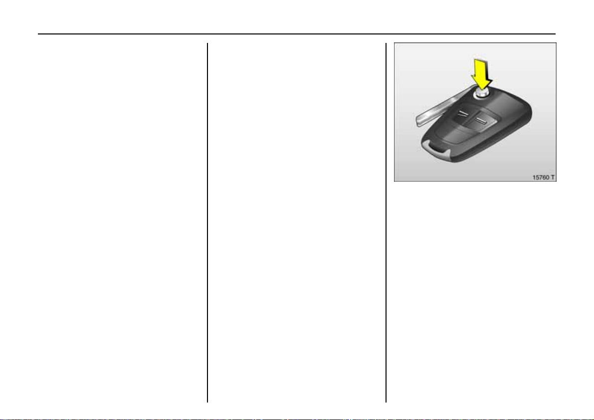
To unlock and open driver’s door:
Pres s bu tton q,
pull door ha ndle
6 Door locks, child safety locks – see
page 22,
key – see page20,
electronic immobilizer – s ee page 21,
ra dio remote control 3 – see page22,
central locking 3 – see page 24,
V aux hall alarm sy stem 3 – see page 31.
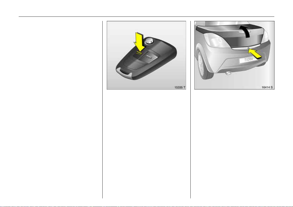
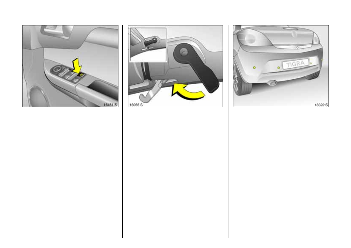
To unlock and open luggage
compartment:
Press button q
of remote control twice,
press butto n be n e ath t he boot lid
The vehicle is unlocked and the luggage
compartme nt opens automatically.
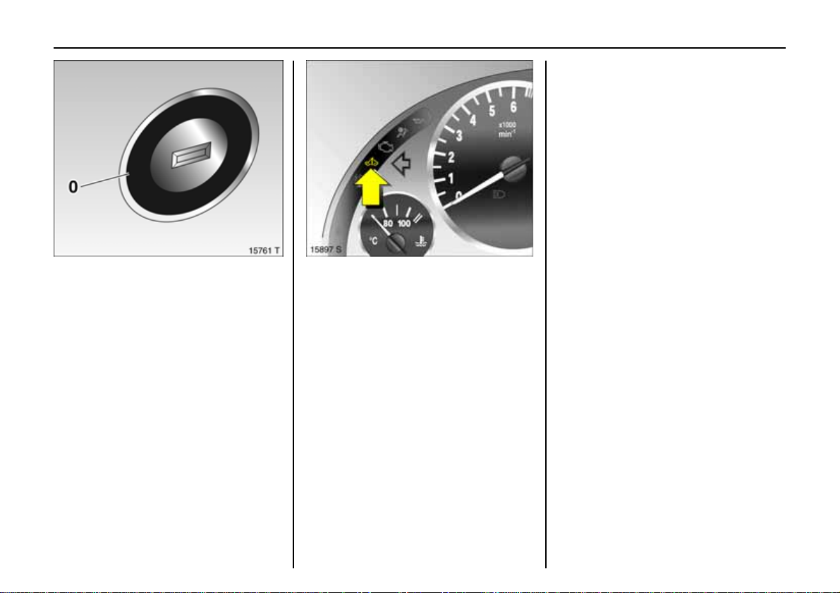
To unlock with but t on on driv er’s door:
With veh icle unlocked, ignition on and
hand brake applied, briefly pull button R.
6 Luggag e co mp artm ent – see page 27,
radio remote control – s ee page 22.
Page 7
3In Brief
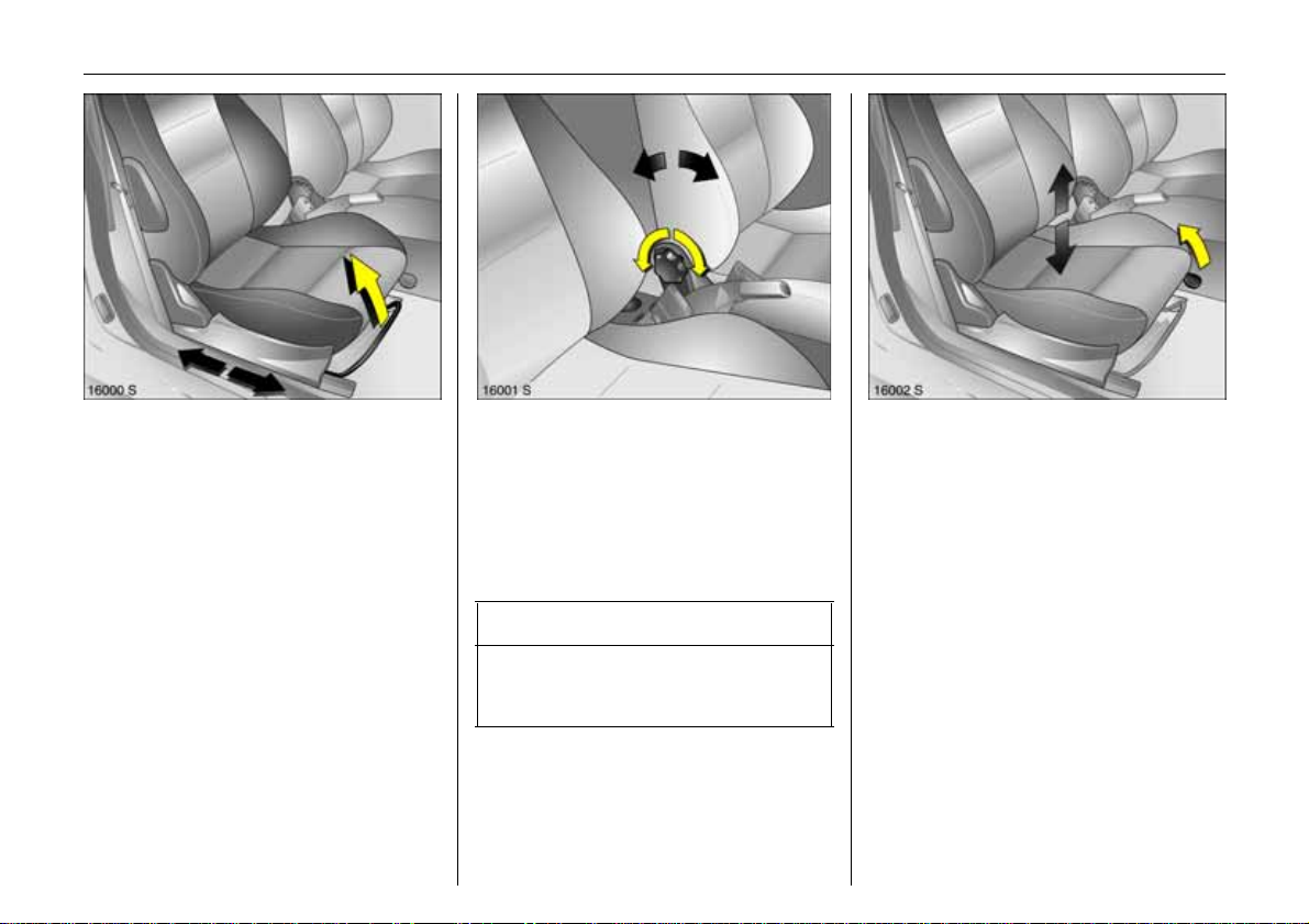
To adjust seat:
Pull handle,
slide seat,
release handle
6 Seats – see page 46,
seat position – see page 47 .
Adjusting seat back rest:
Turn handwheel
Move s eat backrest to su it seating position.
Do not lean on seat backrest whilst
adjusting it.
6 Seats – see page 46,
seat position – see page 47.
9 Wa r n i n g
Important: Do not sit nearer than 10
inches (25 cm ) from the steering wheel, to
permit safe airbag deplo yment.
T o adj u st seat he ig h t :
Pull fro nt lev er at side
Lift lever and relieve some weight from sea t
to raise it or press down on seat with body
weight to lower it.
6 Seats – see page 46,
seat position – see page 47.
Page 8
4In Brief
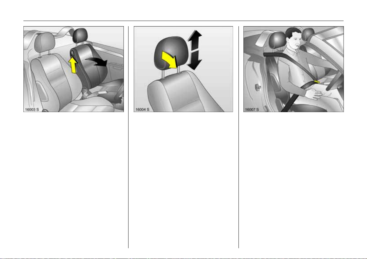
F old in g dow n t he se at backrests:
Rai se release lever
To access the stowage compartment
behind the seats, fold the front seat
backrests forward.
6 Seats – see page 46,
seat position – see page 47 .
To adj ust head r e s t r ain t height :
To rel ease c atch gri p h e ad
restra in t at sides,
ti lt forward,
hold and adjust height,
engage
6 Head restraints – page48,
h ead res traint position – page 48,
h ead res traint removal – page 48.
To fit sea t be lt:
Draw seat belt smoothly
frominerti a reel,
gui de over should er
a n d e n ga ge in bu ckle
The seat belt mu st not be twisted at an y
point. The lap belt mus t lie snu gly against
the body. The backrests must not be tilted
back too far (recommended tilting angle
appr ox. 25°).
To rel ease belt, press red button on belt
buckle .
6 Three-point safety belts – see page50,
airbag system – see page 56,
seat position – see page 47.
Page 9
5In Brief
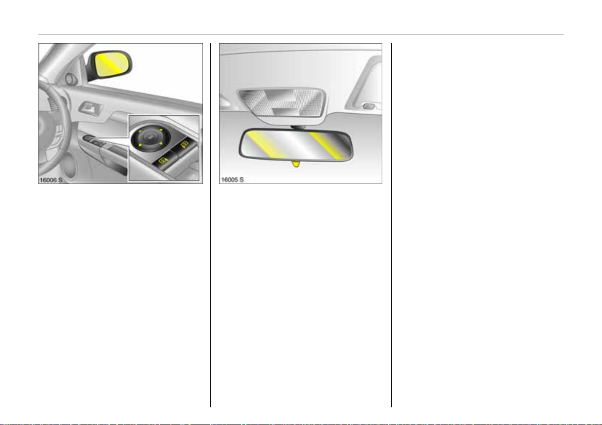
To adjust exterior mirrors:
Four-wa y swi tch on drive r’s d oor
Press mirro r switch right or left: Four-way
switch adjusts corresponding mirror.
6 Mir rors – page 34,
aspherical exterior mirror – page 34,
heated exterior mirror – pages 12, 95.
Adjusting interior mirror:
Swivel mirror hous ing
Swivel lever on underside of m irro r housing
to reduce dazzle at night.
6 M irrors – page 3 4.
Page 10
6In Brief
Page 11

7In Brief
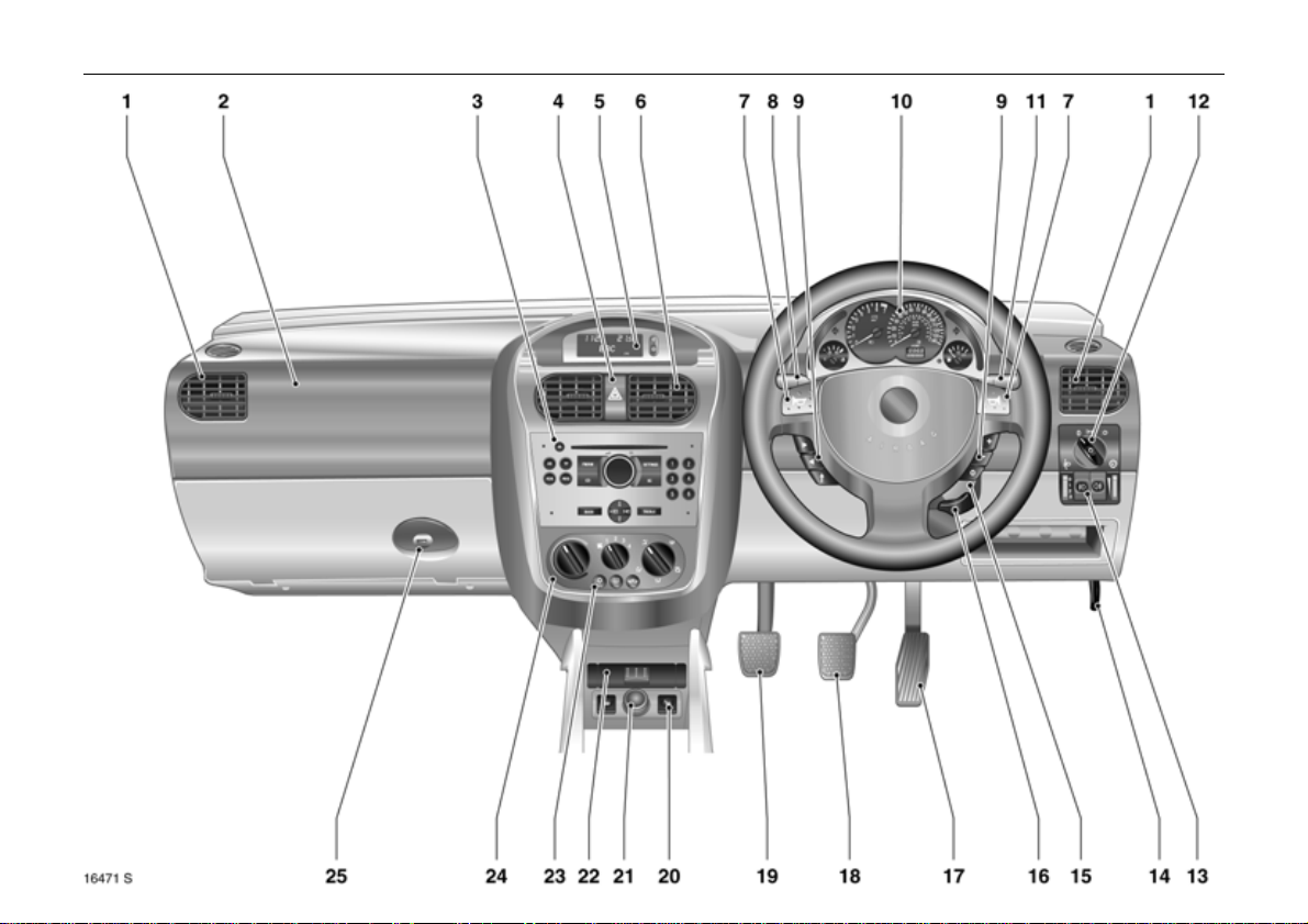
Page
1 Side air vents ................................... 94
2 Fr ont passenger airbag .................. 56
3 In fotainment sy stem 3 ..... ........ 76, 93
4 Hazard warning lights .............. 10, 90
LED for anti-theft alarm s ystem 3...32
5 Informat ion display
for time, date,
outside temperature,
Infotainment System 3 . ........ ..... .... . 76
Trip computer 3 ... .... ..... ........ ..... .... . 8 3
6 Centre air vents ................................94
7 Horn ............. ......... ......... ........ ...........11
Dr ive r’ s Airb ag ..... .... ..... .... .... ......... . 5 6
8 Tu rn sign al l igh ts ,.. .... ......... .... ..... 10, 8 9
hea d lig ht flas h, .... .... ..... .... .... ..... 10, 8 9
Dipped beam, high beam ........... 9, 89
Door-to-door l ight funct ion 3......... 90
Cruise control3 ........ ..... .... .... ..... .... 120
9 Remote c ontrol on
stee ring wheel 3 .. ...................... ..... 92
10 Instruments................................. 68, 74
Pa ge
11 Windscreen wiper ..................... 11, 87
Windscreen wash system ..........11, 87
12 Park ing lights, dipped beam ... ... 9, 88
13 Headlight range adjustment .......... 90
Fog tail light ..................................... 89
Fog lights 3 ...................................... 89
Instrument illumination .. ................. 91
14 Bonne t rele a se lev er . ........ ..... .... .... 1 3 2
15 S ta rter switch with steering
wh ee l loc k ... ..... .... ......... .... ..... .... ..... ... 9
16 Steering wheel adjustm ent 3 ... ..... ... 9
17 Ac cel era t or pedal .... .... .... ..... 108 , 1 10
Page
18 Brake pedal ..................... 72, 108, 123
19 Clut ch p ed al 3 ... ..... .... ......... ..... .... 108
20 Heated seats 3 .. ..... .... ..... .... ......... .. 95
21 Accessory socket or
cigarette lighter .............................. 65
22 Ashtray 3 ......................................... 66
23 Air conditioning s ystem 3 ... ..... .... .. 98
Heated rear window .................. 12, 95
Air recircul a ti on system 3............... 99
24 Climate control ............................... 94
25 Glove compartment ........................ 67
Page 12

8In Brief
Control indicators
X
>
A
Z
v
Seat belt3,
see pages 68 , 50.
Fog lights 3,
see pages 68 , 89.
Engine elec tronics,
Immobilizer,3,
Easyt ronic3,
Fault,
see pages 21, 69, 1 02,114.
Exhaust emission 3,
see pages 69 , 114.
A irbag systems,
Be lt tensio ne rs,
see pages 52 , 60.
I
O
C
!
j
T
r
Engine oil pressure,
see page 70.
Turn signal lights,
see pages 10, 71, 89.
Main bea m,
see pages 9, 71,89.
Glow plugs 3,
see page 70.
Easytronic3,
Start engine 3,
see pages 71, 103.
Easytronic 3,
Winter progr amme,
see page 105.
Fog tail light,
see pages 71, 89.
p
R
u
S
EPS
v
Y
y
Alternator,
see page 71.
Brake system,
Clutch system,
see pages 72, 18 3.
Anti-lock Brake System3 ,
see page 125.
Engin e oil level 3,
see pages 72, 17 9.
Electric power steering3,
see page 72.
Electronic Stability Program
Plus
(ESP®
see pages 73, 11 8.
Fue l level,
see pages 73, 11 3.
Seat occupancy recognition 3,
see pages 73, 61 .
) 3,
Page 13
9In Brief
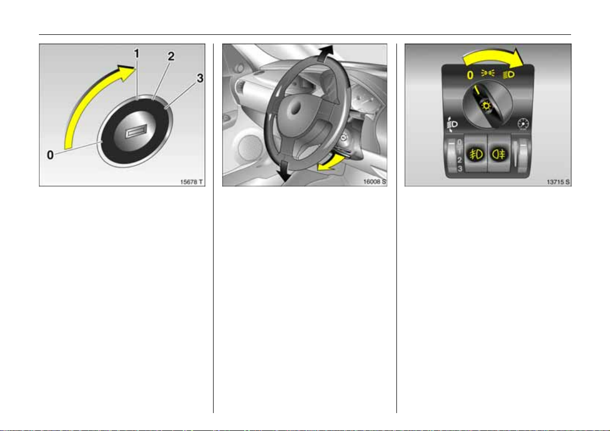
St eering wheel lock and ignit ion:
Turn key to position 1
M ove stee r ing wheel s om e wh at
to release lock
Positions:
0=Ignitionoff
1 = Steering free, ignition off
2=Ignition on,
for diesel engine: preheat
3=Starting
To lock the steering wheel, switch ignition
off, remo ve ke y and engage steering wheel.
6 Starting – page 13,
ele ctro nic immobilizer – pag e 2 1,
parking the veh icle – page 14.
Steering wheel ad ju stment 3:
Swivel lever d o wn,
adjust heig ht,
s wiv el lever up,
engage
Adjust steering wheel only when vehicle is
stationary and steering column lock is
relea sed.
6 Airbag systems – page 56.
Light switch
7 =Off
8 = Par king li ght s
9 = Di ppe d be am
or main beam
Press button:
> =Fog lights3
r = Fog tail light
0 = Cou rtesy light
6 Lighting – page 88,
headlight control indicator – pages 14, 86.
Page 14
10 In Brief
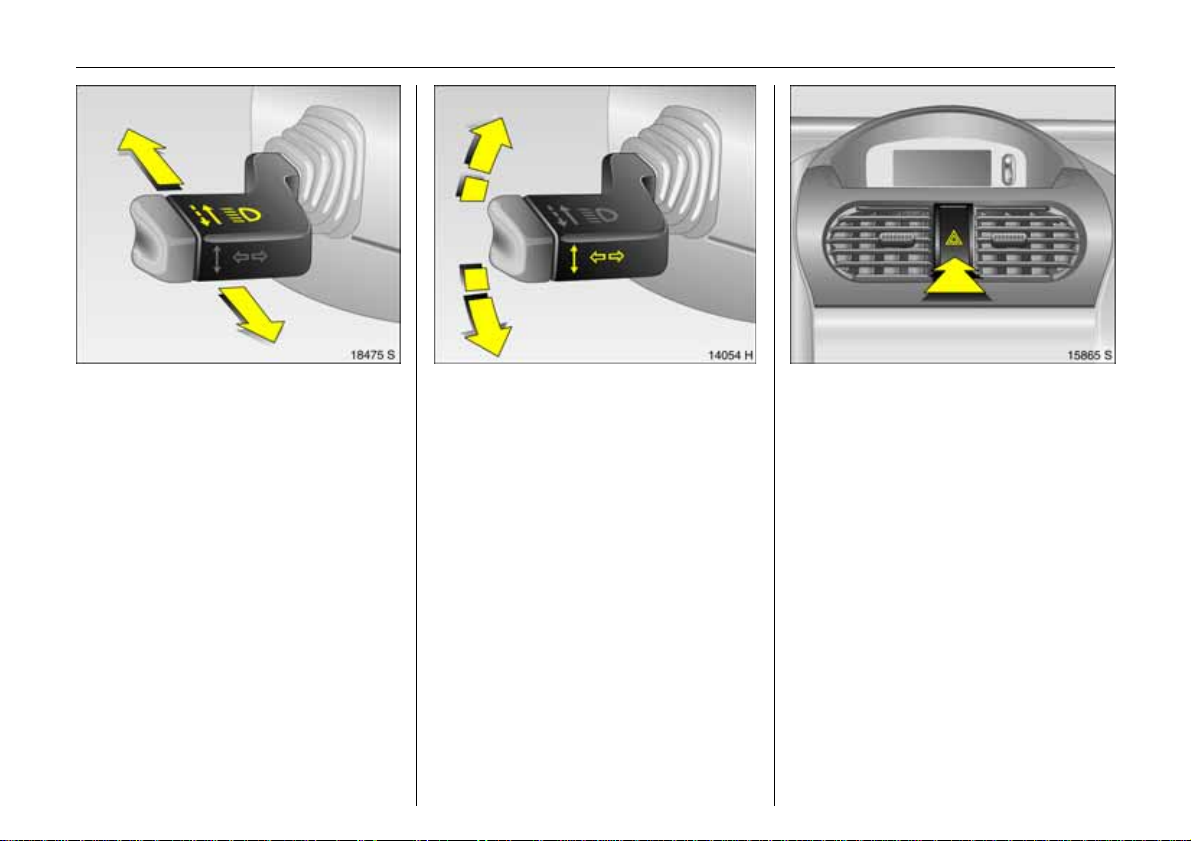
Headlight flash, main beam and
dippe d be am :
Headlight
flash
= pu ll stalk
towards
s t eering wheel
M ai n beam = st a lk for war ds
Di ppe d be am = stalk for w ar ds
again
Main beam, h eadlight flash – page 89.
S w itch on t u r n signal light s:
right = stalk up
left = stalk down
6 Turn s ignal lights – page 89.
Hazard warning li ghts:
on = press ¨
off = press ¨ agai n
6 Hazard warning lig hts – page 90.
Page 15
11In Brief
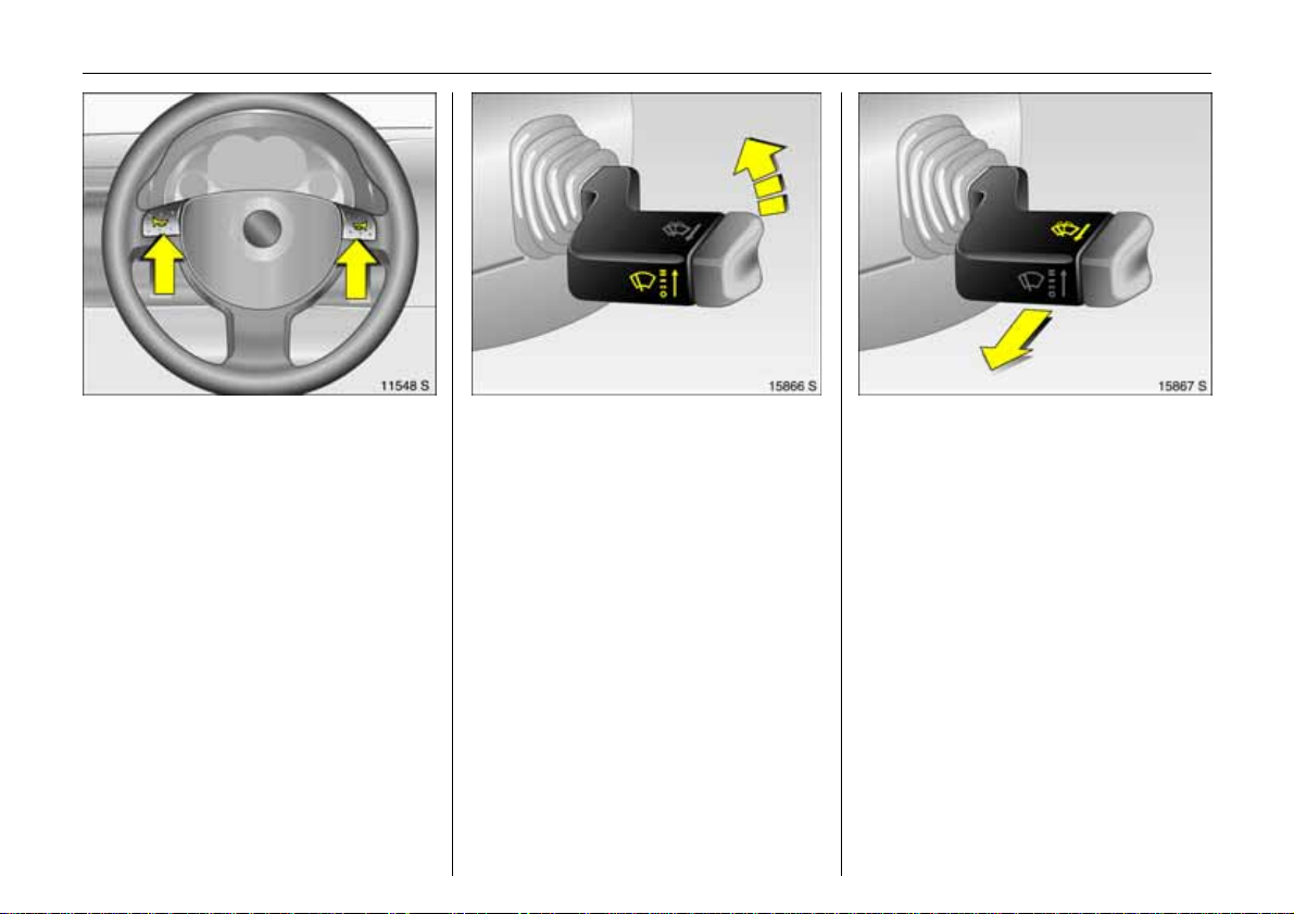
O per at e h orn:
j press right or left
6 A irbag sys tem – page 56,
remote control on steering wheel 3 –
page 92.
Wiper:
Move stalk up
§
=off
$
= adjustable tim ed interval
wipe
%
=slow
&
=fast
6 wiper – page 87,
adjustable timed interval wipe 3 –
page 87,
further notes – pages 1 60, 185.
Operating windscreen system:
Move stalk towa r d steering w heel
The wiper will swipe for a few str okes.
6 Screen wash system – page 87,
further notes – page s 160, 185.
Page 16
12 In Brief
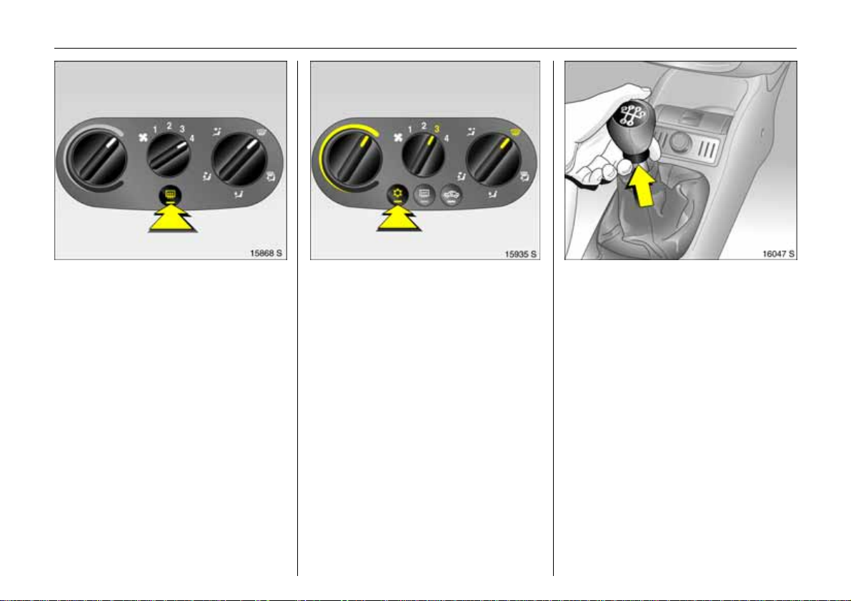
Heated rear window,
heat ed exterior mirrors:
on = press Ü
off = pre ss Ü again
6 A ir conditioning – page94,
heated rear window – page 95.
To c lea r misted or ic y wind ow s:
Turn rot ar y switch for
tempera t ure and air flo w
clockwise,
set air distributi on to V;
Air conditi oning system 3:
A l so pr e s s butt o nn
6 Climate control system 3 – page 94.
Man ual transmission:
Reverse gear: with vehicle stationary, three
seconds after de-clutching pull the ring up
and engage gear.
If the gear does not engage, s et the leve r
in neutral, r elease the clutch pedal and
depress again; then repeat gear selection.
Page 17
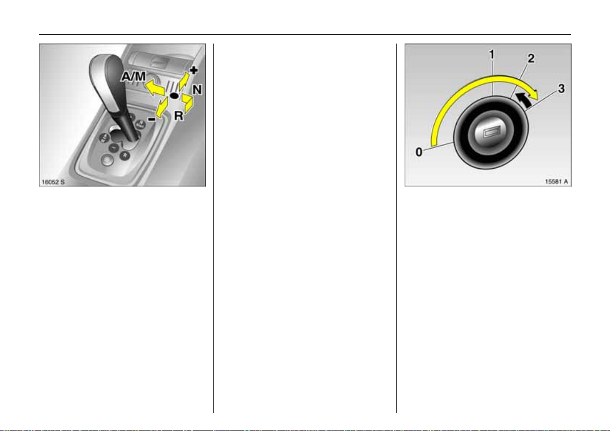
Easytronic 3:
N = Idle/start position
o
=Drive position
(centre position)
+ = Higher gear
-=Lower gear
A/ M = Swi t ch between
Auto m at i c an d
Manua l mode.
R = Rever se gear
(withselector lever lock)
To move the selector lever from N to R
press the button on the lever.
Only star t in N with foot brake applied.
6 Easytronic 3 – page 102.
Before starting off, check:
z Tyre pressure and tyre condition, see
pages 126, 170.
z Engine oil level and fluid levels in engine
compartment, see pages 1 79 to 185.
z All windows, mirrors , exterior lighting
and number plates ar e free from dirt,
snow and ice and operational.
z Do not place any objects in fr ont of the
rear wi ndow, on t he instr ument panel or
in the area in which the airbags inflate.
z Seats, seat belts and mirrors are
correctly adjusted.
z Check brakes.
13In Brief
To start e ng ine:
Operate clutch and brake,
Easytronic 3 in N,
do not accelerate,
petrol engine: key to 3 ;
diesel engine: key to 2, when
con t rol indicator ! goe s o ut1),
key to 3;
relea se key once engine is
running
Before restarting or switching off the
engine, turn key ba ck to 0.
To switch on the ignition, only turn the key
to 2.
6 Electronic immobilizer – Page 21,
Diesel fuel system – Pa ge 132.
1)
Preheating system switches on o nly if outside
temperature is low.
Page 18
14 In Brief
Advice when parking:
z Do not park the vehicle on flammable
ground as combustion could occur due
to th e high exhaus t temperatures.
z Always apply th e hand brake firmly.
Apply the hand brake as firmly as
possible on uphill or downhill slopes.
To reduce operating forces, depress
foot brake at the same time.
z Close w indo ws and Retrac table steel
roof.
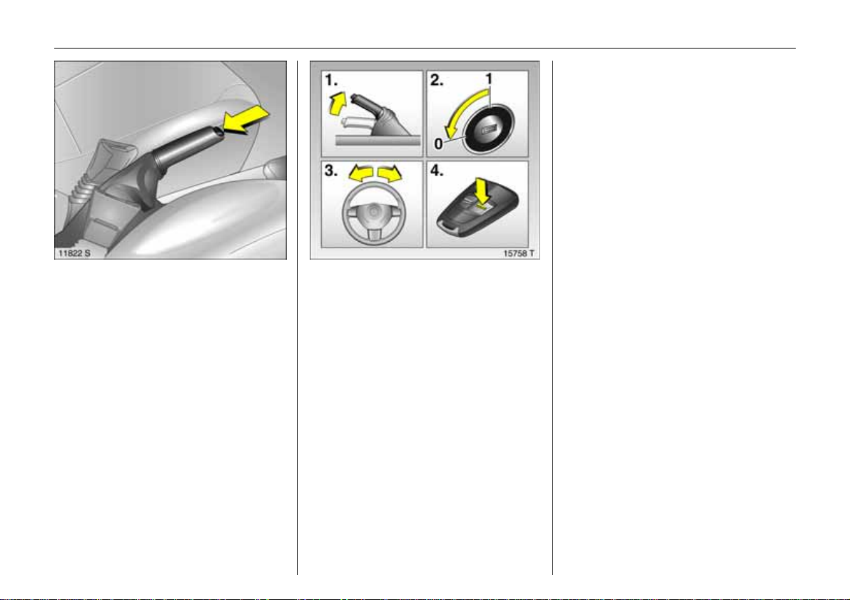
Releasing the hand brake:
Rai se lever slig h tly,
press lock button,
l o wer lever fu lly
6 Hand brake – page 124.
Parking the vehicle:
Apply hand br ake firmly,
engine off,
remove key,
lock steering wheel,
lo ck v eh icle
T o lock and activate the Vauxhall alarm
system 3, pres s bu tton p. To activate the
anti-theft lock ing system 3 and Vauxh all
alarm system 3, press button p twice.
6 F urther informatio n – see p ages 2 1, 1 08,
radio remote control – see page 22,
central locking system – see page 24,
V aux hall alarm sy stem 3 – see page 31,
vehicle deco mmissioning – see page 187.
Page 19
15In Brief
z With man u al transmissi on, select f irs t
gear or reverse gear , with Easytronic 3
move s elector lever to centre position
before switching ignition off.
z On vehicles with Easytronic 3 control
indica to r R flashes for a few sec onds
after the ign ition is switched off if the
hand brake has no t been applied– see
page 106.
z Turn steeri ng wheel until lock is felt to
engage (anti-the ft protection) after first
withdraw ing the ignition key.
z The engine cooling fans may run after
the engine has been switc hed off, see
page 178.
6 Further information – see pages186, 187.
9 Wa r n i n g
Carry out regularly the checks
recommended in the individual sections
of this Owne r’s Man ua l.
Ensure that your vehicle is serviced at the
service intervals specif ied in the Service
Booklet. We recommend that you entrust
this wor k to your Vauxhall Authorised
Repairer.
Have faults remedied without delay!
Consult a workshop. We recom mend your
Vauxhall Authorised Repairer. If
ne cess ary, i nterrupt your jo urney.
6 Maintenance – see page 162.
That was the most i mportant
information for your first drive
inyour Tigra in brief.
Th e ot h e r p age s of th i s ch ap t e r
contain a des cription of some
interesting fun ction s in your
vehicle.
T h e remain ing ch apters
of the Owner’s Ma nual
co ntain im p or t ant info rm a t ion
on op era tion, sa fety and
ma intenance as well as
a com plete index.
Page 20
16 In Brief
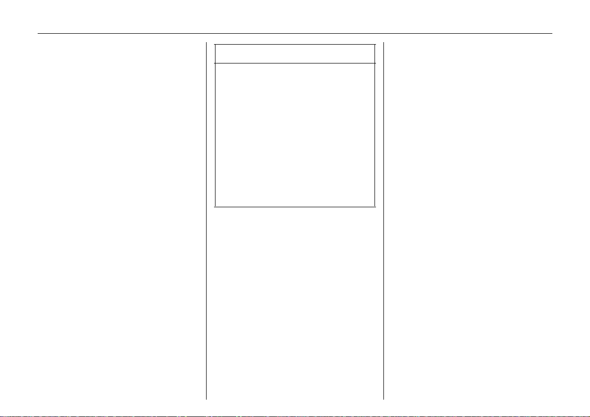
Airbag System
The airbag system co nsist s of several
separate systems.
Front airbag system
The front airbag system will be triggered
in the event of a serious accident involving
a frontal impact an d forms safety cu shions
for the driver and front passenger. The
forward movement of the driver and front
passenger is checked and the risk of
injuries to the uppe r body a nd head
thereby substantially reduced.
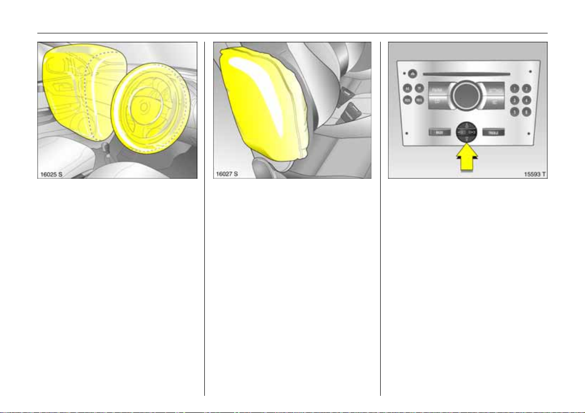
Side airbag system
T he side airbag is triggered in the even t of
a side-on collision to form a safety cushio n
for the driver or front passenger in the
respective door area. This substantially
reduces the risk of i njury to the upper body
and pelvis.
6 Airbag systems – page 56.
Oper at in g menusin
t h e info rma t ion d ispla y 3
Menu options are sel ected using menus and
using the buttons /four-way button or the
multi-functio n button o f the In fotainment
system 3 or the button s 3 on the steering
wheel. The respective menu options are
sh own on the displ ay.
Selection using four-way button:
pres s four-way button at top, bottom, left
or rig ht .
Page 21
Ü Board Computer 19,5° 19:36
BC 1 All values
BC 2
Timer
1
257.0 miles
Ø40mph
6.0 ga l s
8
Ø 7.0 miles/gal
17In Brief
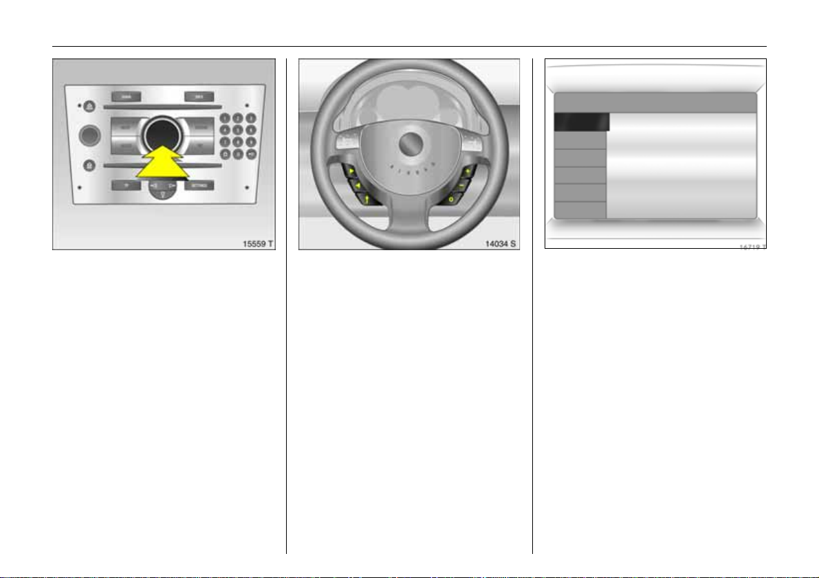
Selection using mu lti-f unctio n button 3:
rotate and press multi-function button.
To exit a menu, turn the multi-fun c tion
button left or rightto Return or Main
and select.
To select wi th steering wheel buttons 3
Select menu options vi a the menus a nd
the buttons.
6 Information Display – page 76.
Trip computer 3
The trip compu ters provide information on
driving data, which is continually recorded
and evaluated electronically.
Functions:
z Range
z Instantaneous cons umpt ion
z Distance travelled
z Average speed
z Effective consumption
z Average consumption
z Stop watch
6 Board computer – see page 83.
Page 22
18 In Brief
Opening Retractab le steel roof
Only with vehicle stationary.
z Engage hand brake.
z Engage the luggage compartment
partit ion in the rear position.
z Place no obj ect s in front of the rear
wind ow or in front of the lugg age
compartment partition.
z Clo se t h e boot lid .
z Release the locking levers on upper right
and left of th e window frames, pulling
both levers all the way down. The
retai ni ng hook must unhook.
z Switch on ignition.
z Pull S until the roof is completely open
and the boot lid is closed.
An acousti c si gna l soun ds at the
beginning and end of the pro cedure.
If the hand brake is not engaged, the
roof lock is not released or the luggage
compartme nt part ition is not folded back
when button S is actuated, a warning
buzzer sounds and the roof does not
open.
6 Retractable steel roof – see page 37.
Page 23
19In Brief
Closing Retractable steel roof
Only with stationary vehicle and closed
boot l id.
The luggage compartment partition must
be engaged in its rear position. Do not
place any objects in front of the luggage
compartment partition.
z Engage hand brake.
z Switch on ignition.
z Press S until the roof and boot l id are
co mpletely closed.
An acousti c si gna l soun ds at the
beginning and end of the procedure.
If button S is actua ted when the h and
brake is not engaged, a warning buzzer
sounds and the roof r emains open.
z Move the locking levers on right and left
of the window frames al l the way up.
Each retaining hook must engage and
the roof must lock securely .
6 Retr actable steel roof – see page 37.
Parkin g distance sensor 3
Whe n reverse gear is selected, the Parkin g
distance sensor switches itself on
automatically.
If the vehicle approaches an obstacle when
reversing, a series of signals can be heard in
the vehicle interior. The interval between
the signals becomes shorter as the distance
is reduced. If the distance is less than 30 cm,
the signal will be con tinuous.
6 P ar king distance s ens or3 – page 122.
Page 24
20 Keys, doors, windows, Retractable steel roof
Keys, doors,
windows, Retractable
steel roof
Replacement keys ............................... 20
Ca r Pass ... .... .... ..... ......... .... ..... .... .... ...... 2 0
Key with re tractable key blade 3 ...... 20
Electronic immobilizer ......................... 21
Radio remote control .......................... 22
Central locking system ........................ 24
Operating central lo cking system with
key in driver’s door lock.................... 27
Lug gage compartment ....................... 27
Vauxhall alarm system 3.................... 31
Exterior mirrors..................................... 34
Interior mirror....................................... 34
Electric windows................................... 35
Retractable steel roof.......................... 37
Wind deflector3.................................. 45
Replacement keys
The key numb er is spec ified in the vehicle
documents and in the Car Pass 3.
The key is a constituent of the elec tronic
immobilizer. Ordering keys from a Vauxhall
A uthorised Repairer guarantees problemfree operation of the electronic
immobilizer.
Keep the spare k ey in a safe spot.
Locks, see p age160.
C ar Pass
The Car Pass contains all of the vehicle’s
data and should therefore not be kept in
th e vehicle.
Have your Car Pass on hand w hen
consulting a Vauxhall Authoris ed Repairer.
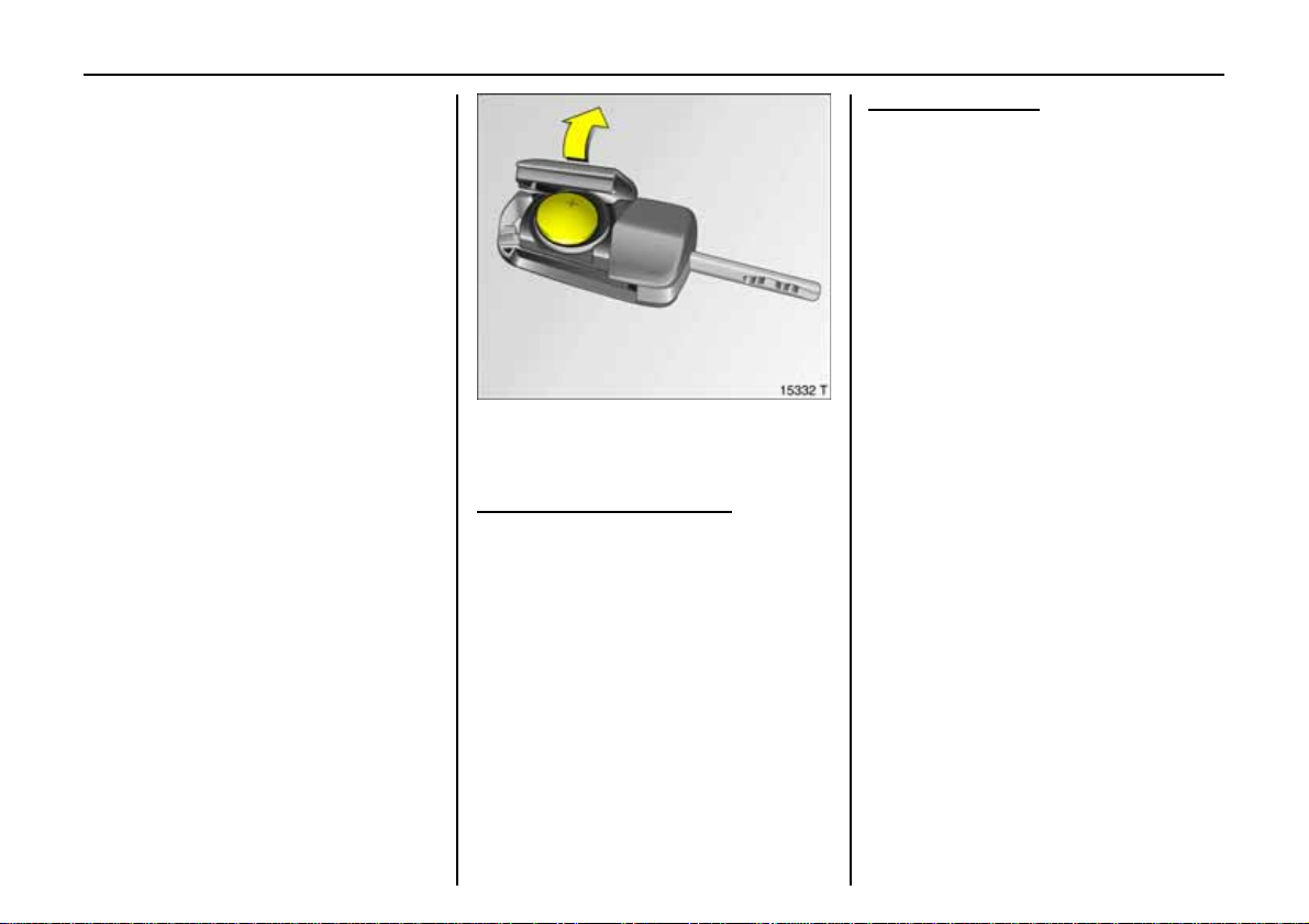
Key with retractable key blade 3
Press button to extend. Press button to
retract; key section engages audibly.
Page 25
21Keys, do ors, windo ws,R etractab le steel roof
If co ntrol indicator A illumin ates a fter
the engine is started, there is a fault in
the engine elec tronics or transmission
electronics 3 (see pages69, 107, 115)
orthere is w ater in the diesel f uel filter 3,
see page 181.
Note
The immobilizer does not lock the doors.
Therefore, always lock vehicle befo re
leaving unattended and enable Vauxhall
alarm system 3 see p age 24.
Electronic immo bilizer
Using a tra nspon d er housed in the key, the
system checks whether the vehicl e may be
started us ing the key that has be en
inserted. If the key is recognised as
"authorised" the e ngine ca n be s tarted.
The electronic immobilizer activates
automatically whe n the k ey is re moved
from the starter switch.
The c ode number of the electronic
immobilizer is given in the Car Pas s.
Control indicator for immobilizer A
Con trol ind ica tor A illuminates briefly
when the ignition is switched on.
If the control indicator flashes when the
ign ition is on, there is a fault in the s ystem;
the engi ne c annot be st arted . Switch off
th e ignition an d then repeat the s ta rt
attempt.
If the control indicator A cont inues to
flash, try to s ta rt the engine using the
second key and contact a workshop f or
assistance.
Page 26
22 Keys, doors, windows, Retractable steel roof
Ra di o remo te con tr ol
Depending on eq ui pment l evel, the veh icl e
comes equipped with one of the remote
controls depicted on this page.
The radio remote control is integrated in
the key.
Us ed to op er at e :
z central locking system,
z mechanical anti-theft locking system 3,
z Va uxhall a lar m system 3 .
The w indows can also be closed using the
radio remote control.
The radio remote control has a range
o f approx. 5 metres. This range can be
affected by outside influences. Aim the
remote con trol at the vehicle to operate.
Handle the radio remote control with
care , protect it from moisture and high
temperatures and avoid unnecessary
op eration.
The hazard warning lights come on
to indicate that the rem ote control is
operational.
Central locking system,
see page 24.
Mechanical anti-theft locking system 3 ,
see page 25.
Vauxhall alarm system 3,
see page 31.
Electric windows,
see page 35.
Page 27
23Keys, do ors, windo ws,R etractab le steel roof
Fault
If the central locking system cannot be
operated with the radi o remote control,
it may be due to the follo wing:
z The range of the radio remote control
has been exceed ed.
z Radio remote control battery voltage is
too low.
z F requent, repeated operation of
the radio remote control out side the
reception range of the ve hicle (e.g. too
far from ve hicl e, remote control is th en
n o longer recognised). See remote
control synchr onisat ion.
z If the central locking system is
o verloaded as a result of repeated
o peration at short intervals. The power
s upply is cut off for a brief peri od .
z Interference from higher-power radio
waves fr om other sources.
To eliminate the cause of a fault, we
recommend contacting a workshop
for assistance.
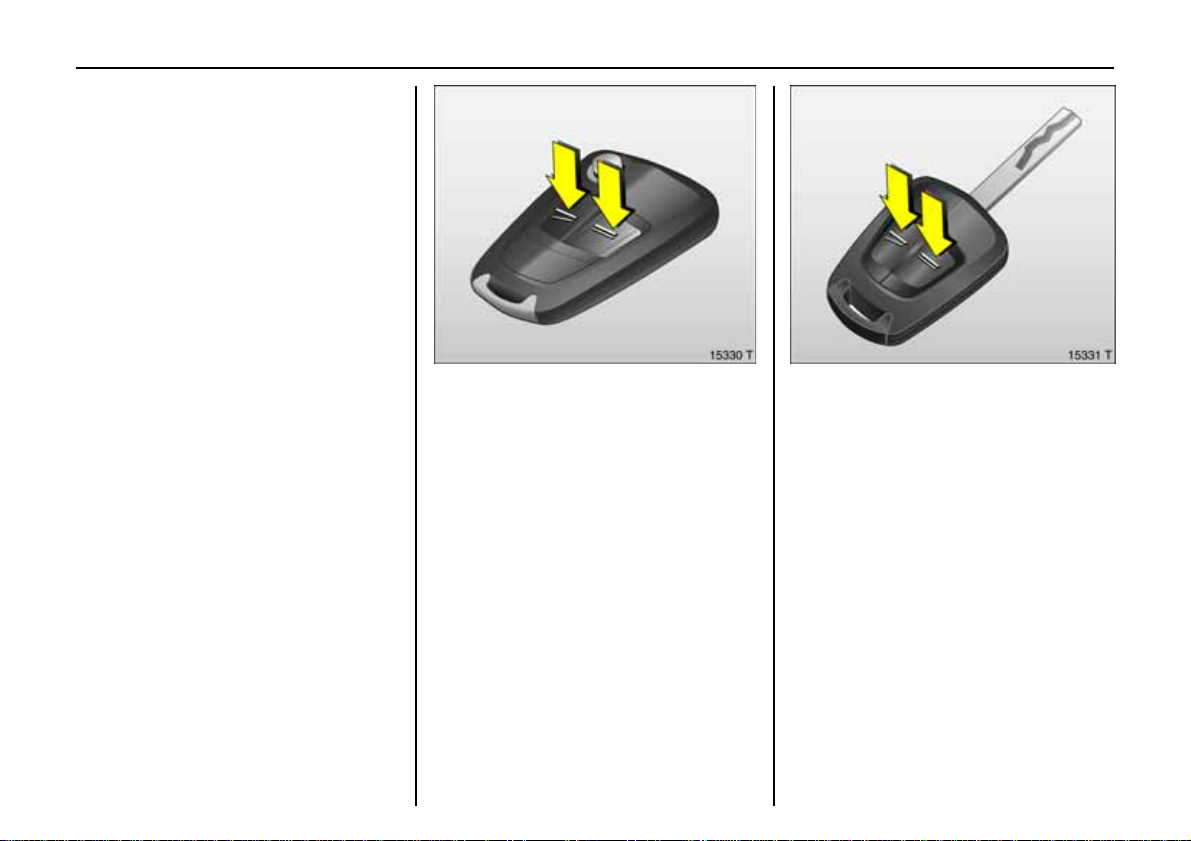
Open driver’s door with key – see page 27.
K ey with fix ed blade, see Fi g. 15331 T o n
previous page.
Have the workshop change the battery.
In t he event of a functional i ty p roblem
or battery replacement, sy nchronize the
radio remote co ntrol.
After changing the battery, unlock the
door using the key in the lock, see overleaf.
The radio remote control i s synchr o nized
by inserting th e key in the ignit ion lock.
Remote control battery replacement
Replace the battery as soon as the range of
the radio remote control begins to shrin k.
Ke y with re trac ta ble k ey blade,
seeFig. 15330 T on previous page.
Extend key, see page 20. Open radio
remote control. Replace battery (batte ry
type, see page 172) not ing installation
position. Close radio remote contr ol.
Mak e sure that you dispose of old batteries
in accordan ce with environmental
protection regulations.
Page 28

24 Keys, doors, windows, Retractable steel roof
Cen tra l locking system
For doors, boot lid/tailgate and tank flap.
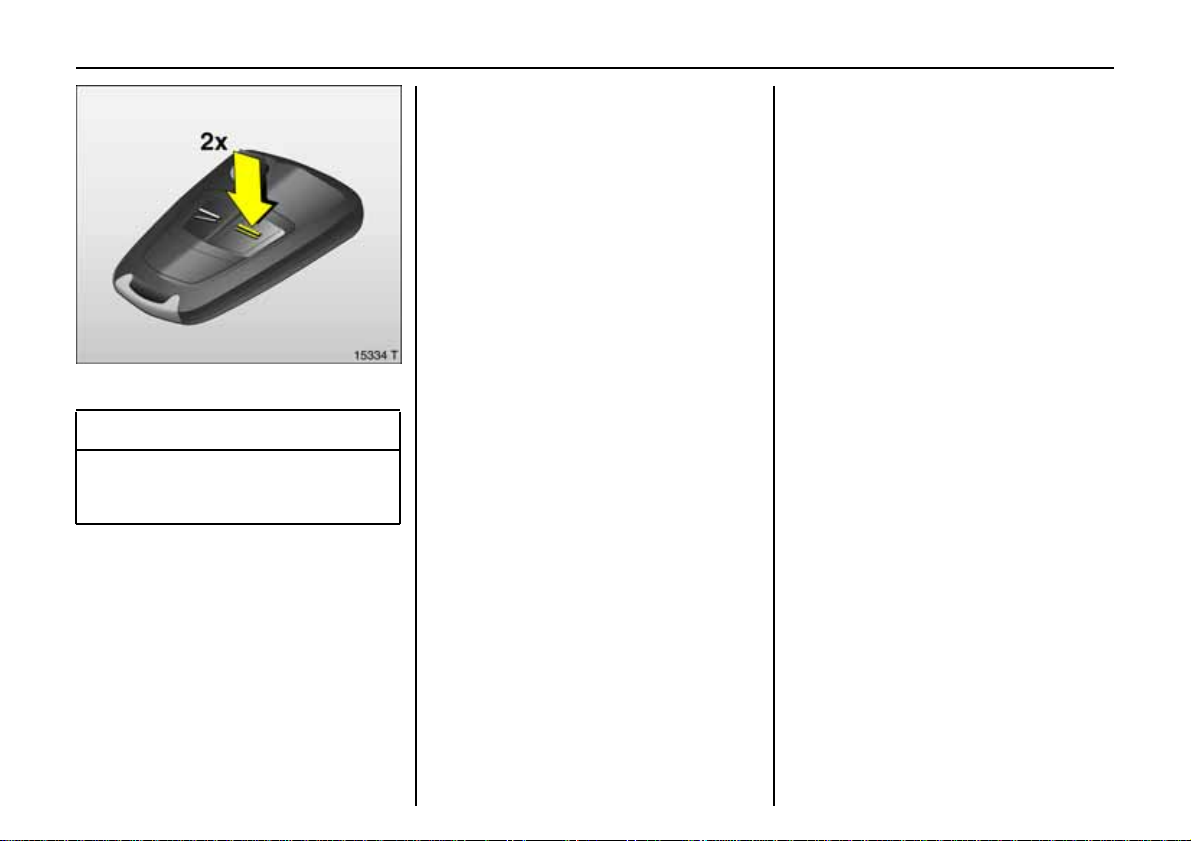
To unlock
Unlock driver’s door only
Press button q on remote control once .
Unlock entire car
Press button q on remote control twice.
The veh icle can also be unlocked by pulling
the door handles if the anti-theft locking
sy stem is disabled.
To lo c k
Close doors, luggage compartment and
tank flap.
Press button p on radio remote con trol.
– or from the inside –
Press button m in the door.
The vehicle can be locked even if the driver’s
door is open. Risk of being locked out.
Page 29
25Keys, do ors, windo ws,R etractab le steel roof
Mechanical anti-theft locking system 3,
9 War n ing
Do not use the system if t here are people
in the vehicl e! The doors cannot be
u nlocked from inside.
All d oors must be closed. No more than
10 seconds after locking, pres s button p
on the r adio r emot e cont rol again.
Lo ck but t ons on all door s are pos itioned
such that doors cannot be opened.
If the ignition was on, the driver’s door
must be opened and closed once so that
the vehicle can be s ecured.
Note
z 30 seconds af ter unlocking using the
radio remote control the doors lock
again automatically if no door is
opened.
z To lock the doors from inside (e.g. to
prevent unwanted entry from outside),
pre ss central lock ing switch m in the
door tr im.
z The vehicle can be locked without the
n eed for the key. With the driver’ s door
open, press central locking switch m in
the d oor t rim and then close the driv er’s
door . Note that un i ntentional actuation
could cause one to be locked out.
z Locked doors and luggage compartment
u nlock a utomatical ly in the event of an
accident of a certai n severity (to permit
outside assistance). Prerequisite: Ignition
must not be switched off.
Page 30
26 Keys, doors, windows, Retractable steel roof
Closing windows from outside
9 War n ing
Exer cise care when operati ng electric
wind ows. Risk of injury, especially for
children.
Vehicle passengers shoul d be informed
according ly.
Keep a close wat ch on the wi ndows
whenclosing them. Ensure tha t nothing
becomes trapped in them as they move.
Fault
If the central locking cannot be operated,
this can be for one of the following reasons:
z If the central locking system is
overloaded as a result of repeated
operation at short intervals. The power
supply is cut off for a brief period.
z Defective fuse in fuse box, see page 148.
To eliminate the cause of a fault, we
recommend contacting a workshop for
assistance.
Operate driver’s door with key, see overleaf.
The windows c an be closed from outside:
hold button p on the remote control
depressed until the w indo ws ar e
completely closed.
Further information on electric windows,
see page 35.
Page 31

To lo c k
W ith doors closed, turn key towards rear of
vehicle as far as it will go. Turn key back to
vertical position and remove.
27Keys, do ors, windo ws,R etractab le steel roof
Ope rating centra l lo c king sys t em
w ith k ey in driver’s do o r lo ck
To unlock
Turn key forward in lock as far as it will go.
Tur n key back to vertical position an d
remove.
If th e anti-the ft locking sy stem 3 is
engaged, only the driver’s door will unlock.
To unlock the entire car: switch on the
ignition, press central locking switch m
and pull the driver’s door handle.
Luggage com partment
To open with the button in the door
1.Unlock entire vehicle – see page24.
2.App ly hand brake .
3. Switch on ignition.
4. Briefly pres s button R. The opening
process begins after a slight delay.
A s ec on d pr es s of t he b utt on st op s th e bo ot
lid from openin g.
If the hand brake is not engaged when the
button is pressed, a warning buzzer soun ds
and the luggage compartment remains
clos ed.
Page 32

28 Keys, doors, windows, Retractable steel roof
A tone sounds when the boot lid is
completely closed. Locking of the boot lid is
indicated by a single flash of th e hazard
warning lights.
To open with the button beneath the
bootlid
1. Unlock entire vehicle – see page 24.
2. Briefly press the button bene ath the
boot lid. The opening process begins
after a slight delay.
A second press of the button stops the
bootlid f r om opening.
If the ignition is on but the hand brake is
not applied when the button is pressed,
a warning buzzer sounds and the luggage
compartment remains closed.
To cl o s e
P ress the button below the boot lid until
the boot lid is completely closed.
If the ignition is o n but the hand brake is
n ot applied when the button is pressed,
a warning buzzer sounds and the luggage
compartment close s.
Page 33

29Keys, do ors, windo ws,R etractab le steel roof
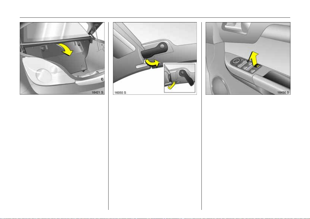
Fault
The luggage compartment lid can only be
operated if t he roof has been full y and
correctly closed or open ed beforehand.
In the eve nt of automatic drive malfunction
or loss of ba ttery p ower, the boot lid is
manually opened as follo ws:
1.Open the d riv er’s door.
2. Fold down the driver’s s eat backrest. The
tool is fastened underneath the seat.
3.Turn the tool 90° to the right to remove .
4.Pull the front of th e too l upward and out
of the floori ng.
5. Pull the tool forward out o f the flooring.
Page 34

30 Keys, doors, windows, Retractable steel roof
6. Open and fold down the cover of the
emergen cy release cab le. Pul l the cable
o ut slightly.
7. Inser t the tool through the eye of the
emergen cy release cab le. Supp or t the
rounded end of the tool on the cover
as illustrated. The eye of the emergency
release cab le must l ie in the groove on
the tool.
8. Have a second person hold the rear of
the boot lid down. Pull the tool forward
to release the boot lid in the rear.
9.Carefully open the boot lid by hand.
Refit the emergency release cable in the
o pening and refit t he cover. Do not close
the c ar door i f the c over is open.
To close the boot lid, have a second p erson
help you press it down and engage it in the
lock.
Have the cause of the fault eliminated by
aworkshop.
Page 35

Va uxhall alarm system 3
monito rs
z doors, luggage compartment, bonnet
z the pass enger compartment
z vehicle tilt, e.g. if it is raised
z the ignition.
9 War n ing
Do not use the system if t here are people
in the vehicl e! The doors cannot be
u nlocked from the inside.
31Keys, do ors, windo ws,R etractab le steel roof
To activ ate
All doors, window s, Re tractable steel roof,
lu ggage compartment and bonnet must
be closed. Press button p on the remote
con trol to lock all the doors and activate
the Vaux hall al arm system 3.
If the ignition was switched on, the driver’s
door must be op ened and closed once so
that the Vauxhall alarm system can be
switche d on.
Activation witho ut monitoring of
passenger compartment and vehicle tilt
e.g. if animals are to be left in the vehicle.
1. Th e luggage compartment, Retractable
steel r oof and bonnet must be c losed.
2. Press the button in front of the courtesy
light (with ignition off); LED in hazard
warning light button flashes a maximum
of 10 seconds. See next page.
3.Cl ose doors.
Page 36

32 Keys, doors, windows, Retractable steel roof
4. Activate the Vauxhall alarm system. The
LED in the hazard warning light button
illuminates. After approx. 10 seconds,
the Vauxhall alarm system is activated
with out monitorin g of the passenger
compartment or vehicle til t. The LED in
the wa rning light b utton flashes until the
Vauxhall alar m system is deactivated.
Pass en ger compartment monitoring is
deactivate d if the Retractable steel roof is
open to prevent false alarms.
Light emitting diode (LED)
During the fi rst 10 seconds o f Va uxhall
alarm system activation :
z LED come son
z LED flashes
quickly
= Test, switch-on delay,
= Door, luggage
compa rtment
or bonnet open,
sy stem fault.
After the fi rst 10 se c onds of Vaux hall a l arm
system activation:
z LED flashes
slowly
z LED comes on
for approx.
1second
If a system fault occurs, contact
a works hop for assistance.
=System switched on,
= Switc h-off function.
Page 37

33Keys, do ors, windo ws,R etractab le steel roof
To deactivate
Press button q of the rad io remote control
– or –
turn on ignition.
If there is a fault in the radio remote control,
unlock vehicle as described on page 27.
If the alarm is triggered when the driver’s
door is ope ned, deactivate the Vauxhall
alarm system by switching on the ignition.
Note
z Changes to the vehicle in terior, such as
th e us e o f se at co ve r s, co uld imp ai r th e
function of passenger compartment
monito r ing.
Alarm
An alarm can be triggered whilst the
Vauxhall alarm system is switched on:
z an acoustic signal (horn) and
z a visual signal (hazard warning lights ).
The number of alarms and t he duration
th er e o f are st ipu l at ed b y la w .
The alarm can be silenced by pressing
a button of the radio rem ote control or
by switching on the ignition. The Vau xhall
alarm system is deactivated at the same
time.
Page 38

34 Keys, doors, windows, Retractable steel roof
Exterio r mirrors
Adjustment using the fou r-way switch in
the driver’s door. Press mirror switch right
or lef t: Four -way switch ad jus ts
corresponding mirror.
Aspherical exterior mirror 3
increases the field of view. Estimating the
distance away of vehicles following you is
only possible to a limited extent because
of sl ight dis tortion.
Swinging in exterior mirror
For the safety of pedestrians, the exterior
mirrors will swing out of their normal
mounting position if they are bumped with
sufficient force. Reposition the mirror by
applying slight pressure to the mirror
housing.
Interior mirror
To adjust, swivel mirror housing.
Swivel lever on underside of mirror hou sing
to reduce dazzle at night.
Page 39

35Keys, do ors, windo ws,R etractab le steel roof
Elect r ic window s
9 War n ing
Exer cise care when operati ng electric
wind ows. Risk of injury, especially for
children.
Vehicle passengers shoul d be informed
according ly.
Keep a close wat ch on the wi ndows
whenclosing them. Ensure tha t nothing
becomes trapped in them as they move.
Ready for operation when the ignition ison.
Operation wit h two switches in the drive r’ s
door handle for the driver’s and passenger
window. Additional switch in passenger
door ha nd l e .
T o operate window in stages, brie fly pull or
pu sh re leva nt wind o w swi tc h. F or autom ati c
o pening or closing, pull or push switch
longer; push or pull switch again to stop
movement.
A utomatic closing is not possible during
Retrac tab l e steel ro of operation.
When a door is opened, the window of that
door opens a sli t. It cl oses automatic ally
after the door is closed.
When the Retractable steel roof is opened
or closed, the windows open a slit. They
close automatically once the Retra c table
steel roof is completely opened or closed.
Safety function
If the window glass encounters resistance
abov e the middle of the window during
automatic closing, it is immediately
stopped and the window opened again.
If the windows do not move easily because
of frost, for example, repeatedly tap th e
switch for the window in qu estion until the
window has bee n closed in sta ges.
Page 40

36 Keys, doors, windows, Retractable steel roof
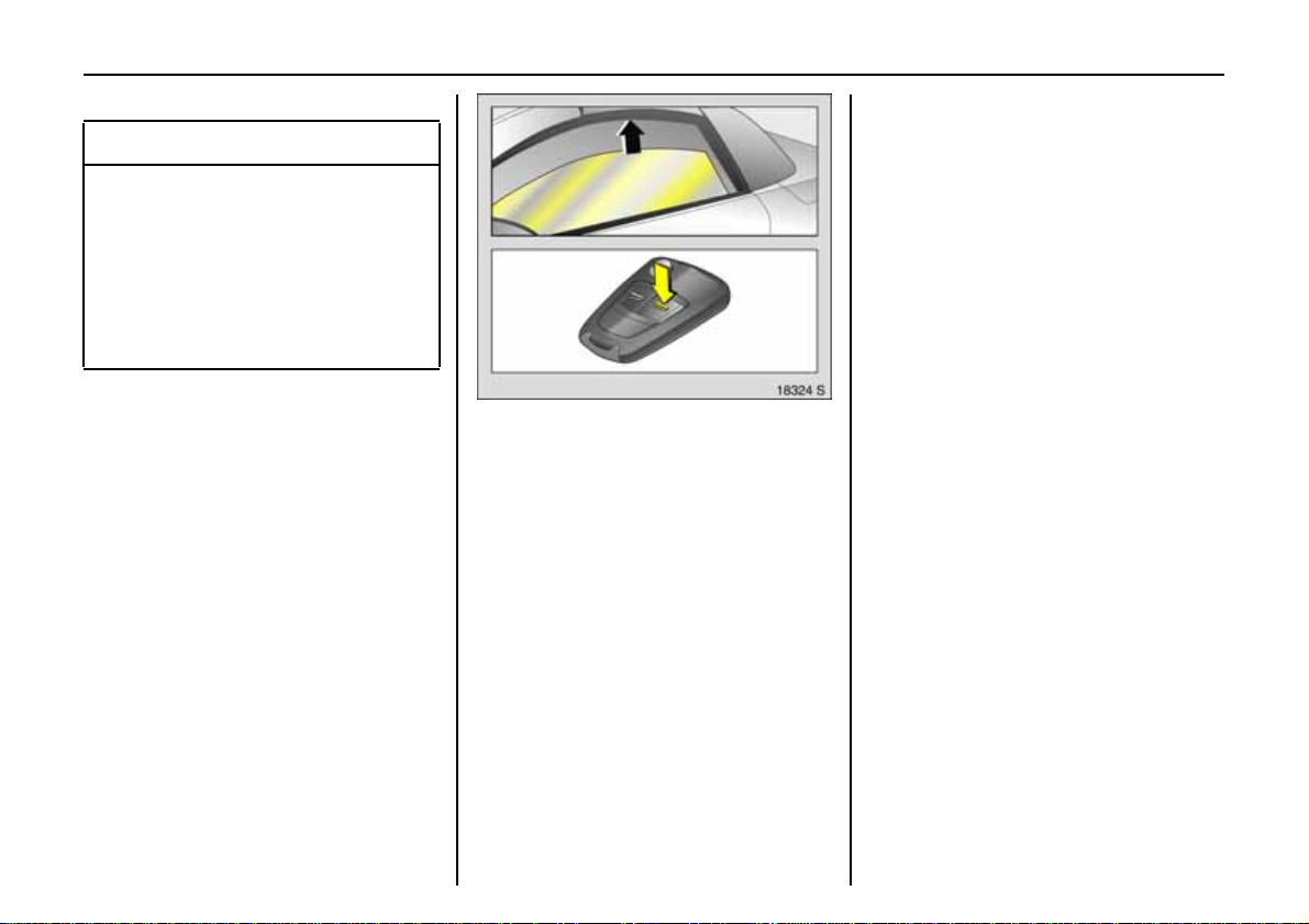
Closing windows from outside
Press button p on the remote control until
the window s ar e closed.
Overloa d
If the windows are repeatedly operated at
short intervals, the power supply is b riefly
cut off .
T he sy ste m is pro tec te d by fuse s i n the fu se
box, see page 148.
Fault
The wind ow s c annot be automatically
opened or closed.
Activate electronic windows as follows:
1.Cl ose doors.
2. Switch on ignition.
3. Windo w com pletely ope n.
4.Cl ose the wind ow s and hold the switch
pressed for at least another s econd.
5. Repeat for each window.
Page 41

Ret ra cta b le st eel roof
The Retractable steel roof, a foldable steel
top, enables the Tigra to combine the
attributes of a coupe and a con vertible.
9 War n ing
Exercise care when opera t ing the roof.
Risk of in jury.
Pay close attention to the roof’ s
movement z o ne during opera tion. Make
sure that nothin g could become trapped.
Make sure no on e is in th e movement
zone during roof operation. Risk of injury.
Before operating the roof in garages,
parking garages or the like, check the
amount of vertical clearance available.
Vehicle passengers shoul d be informed
according ly.
Before l eaving the vehicle, remove the
ignition key in order to prevent
unauthorised ope r ation of the win dows
and s un roof.
Opening the roof
Only with vehicle stationary.
Apply hand brake.
37Keys, do ors, windo ws,R etractab le steel roof
Engage the luggage compartment
partition in the rear position.
Place no ob je cts in front of the rear w indow
or in front of the luggage compartment
partition.
C lose lug gage compartme nt lid , s ee
page 27.
Page 42

38 Keys, doors, windows, Retractable steel roof
Release the locking levers on upper right
and left of the window frames, pulling both
levers all the way down . Both retaining
hooks must unhook.
Switch on ignition.
Pull S until the roof is completely open and
the boot lid is closed.
A n acoustic signal sounds at the beginning
and end of the proced ure .
If the hand brake is not engaged, the roof
lo ck is not released or the luggage
compartment partit ion is not folded back
when button S is actuated, a war ning
buzzer sounds and the roof does not open.
Closing the roof
Only with st ati onary vehicle and close d
boot l id.
The luggage compartme nt p artition mus t
be engaged in its rear position. Do not
place any objects in front of the luggage
compartme nt partition.
Apply hand brake.
Switch on ignition.
Page 43

39Keys, do ors, windo ws,R etractab le steel roof
Press S until the roof and boot lid are
comple tely closed.
An acoustic signal sounds at the beginning
and end of the pr ocedure.
If button S is actuated when the hand
brake is not engaged, a warning buzzer
sounds an d th e r oof remains o pen.
P ush the locking levers on the right and left
side of the wi nd ow frame all the way up.
T he retaining hooks must engage in the
corresponding recess an d the roof must
securely lock.
Note
z A warning buzzer sounds for 5 seconds
after the hand brake is released and the
vehicle starts off if the roof has not been
properly closed or opened. Remedy this
by s topping t he vehi cle and repeating
the closing or opening pro cedure .
z Frequent operation of th e roof with the
engine switched off will discharge th e
battery.
Fault
Automatic roof operation is only functional
if the roof has been properly closed or
opened beforehand.
Check if:
z the hand brake is applied
z the ignition ison
z the luggage compartment partition is
loc ked in the rea r position
z the boot lid is completely closed
z the locking levers are unlocked.
If a f ault occurs while the roof is opening or
closing, t he roof stops in its current position.
A warning buzzer sound s afte r 2minutes.
After an additional minute, power to the
system is cut-off. The roof then moves
automatically back to the luggage
compartment or toward the windscreen
fra me. In order to close compl etely, open
both windows, remove the key and carry
out the missing steps of t he fol lowing
description for loss of automatic drive.
Page 44

40 Keys, doors, windows, Retractable steel roof
If there is a fault in the automatic drive or
loss of battery power, the f ul ly ope ned roof
can be manually closed as follows:
1. Park the vehicle and apply the hand
brake.
2 . O pe n b o t h w i n d o w s or op e n t h e d oo r s.
3. Switch off the ignit ion and remo ve the key.
4.Open the luggage compartment. If the
battery has become discharged or there
is a malfuncti on in boot lid operation, the
boot lid mu st be opened manually; see
page 29.
9 Wa r n i n g
Exe rcise care wh en operating the roof.
Risk of i njury. Risk o f pinching .
Make sure that nothin g could become
trappe d.
Vehicle passengers should be informed
accordin gly.
Closing the roof manually requires
2 perso ns and the use of great care.
5. Fold down the driver’s seat backrest. The
tool is fastened un derneath the seat.
Page 45

41Keys, do ors, windo ws,R etractab le steel roof
6. Turn the tool 90° to the right to remove.
7.Pull t he front of t he tool upwar d and out
of the flooring.
8.Pull the tool forw ard out of t he flooring.
9. Us e the tool to forcefully pull the lock bar
to unlock the cover in front of the rear
window. The lock bar is on the right side
of the car below the cover.
Page 46

42 Keys, doors, windows, Retractable steel roof
10.With the lock bar pulled, have a helper
pivot the cover upward by hand. The
noise aris ing from this is normal.
11.Pres s the button below the boot lid until
the boot lid is completely closed. See
page 28.
If this is not possible, force the boot lid
closed again as illustrated; it mu st
completely engage in the rear lock.
12.Release the front catches of th e boot lid
using the tool by inserting the tool in the
guide and pressing the upper end
inward; see figure. At the same time,
pull the boot lid slightly upward out of
the catch. Carry out the procedure on
the right and left.
Page 47

43Keys, do ors, windo ws,R etractab le steel roof
13.With two people wo rking simultaneously
on the right and l eft, open the boot lid
rearward to its end position. Do no t twist
or tilt the boot lid when doing so.
9 War n ing
Luggage compartment does not remain
in open position.
14.Relea se the roof retaine r a t the rear l eft
of the lug gage compartme nt partition
by raising th e release lever.
15.With the aid of a second person,
carefully an d slowly pull the roof
upward. Grip the roof at the sides and
pull forward. Make sure t hat the boot
lid is completely o pen.
9 Wa r n ing
Cauti on. Risk of pinching.
Page 48

44 Keys, doors, windows, Retractable steel roof
16.Pull the r oof up to the wi ndscre en frame . 17.Push the locking levers on the r i ght and
left side of the window frame all the
way up.
The retaining hooks must engage in the
correspond ing recess and the r oof must
securely lock.
18.Have a second person help to force the
boot lid closed simultaneously on the
right and left. It must engage in the
locks.
Do not twist o r tilt the boot lid.
The closed boot lid is not locked.
Page 49

45Keys, do ors, windo ws,R etractab le steel roof
19.N ext, if possible open and cl ose the
boot lid once using the button below
the boot lid. The boot lid is then locked.
20.Press down the cov er in front of the rear
window.
It is not poss ible to open the roof if there is
a malfunctio n in automatic operation.
Have the cause of the fault e li m inated by
aworkshop.
Win d deflector 3
Install the wind deflec tor to reduce wind
turbulence, draught and noise in the
passenge r co mpartment when the
Retrac t able stee l roof is open.
Insert the wind def l ector in the opening in
the ce ntre of the rollover protection and
fasten it with the crank.
When removed, store the wind deflector
in the lugg age compartme nt.
Page 50

46 Seats, Interior
Se ats, Interi or
Fr ont seats ........................................... 46
Head restraints .................................... 48
Lug gage compartment partition. ...... 49
Three-stage safety system.................. 50
Three-point seat belts ......................... 50
Be lt ten sion e rs. ..... .... ......... ..... .... .... ..... . 5 2
Using the belts ..................................... 54
Child res traint systems 3 .................... 55
Airbag System...................................... 56
Cigarette lig hter 3............................... 65
Accessory socket 3.............................. 65
Ashtray 3 ............................................. 66
Stowage compartments...................... 66
Coin holder 3....................................... 67
Sun visors.............................................. 67
Fr o n t seat s
9 Wa r n i n g
Never adjust seats during driving, as they
ca n move unc ontrollably.
Adjust seat longi tudinally
To adjust, pu l l the handle on the front seat,
slide the seat and release the handle.
9 Wa r n i n g
Adjusting the backrest
To adjust, turn side ha ndwheel on the seat
while releasing the load on the backrest.
Mov e seat b ackre st t o s uit seati ng positi on.
Do no t sit nearer than 10 inches (2 5cm)
from the steering wheel, to permit safe
airbag deploy ment.
Page 51

47Seats, Interior
Adjusting the seat height
To adjust, lift lever and relieve some weight
from seat to raise it or press down on seat
with body weight to lower it.
Fold backrest forward
To fold the backrest forwards, e.g. to re ach
the storage c ompartment behind the seats ,
lift release lever.
Sea t position
Adjust driver’s seat such th a t with the drive r
sitting upright th e steering wheel is held in
the area of its upper spokes with the driver’s
arms slightly bent.
Push passenger seat as far back as
pos sible.
The seat backrests mu st not be t ilted too
far back (recommended tilting angle
appr ox. 25°).
9 Wa r n ing
Failure to observe the descriptions could
lead to in juries which could be fatal.
Vehicle passengers should be informed
accordingly before starting off.
Page 52

48 Seats, Interior
Head restraints
Adjustment
To adjust the head restraints, hold at side,
tilt f orwards, hold and adjust height. Allow
head restraints to engage afte r adjustment.
Head restraint position
The middle of t he head restra int sh ould
beat eye level . If this is not possible for
extremely tall persons, set to highe st
positi on, and se t to lowest position for
sma ll per s o ns .
9 Wa r n i n g
Failure to observe the descripti ons can
lead to in juries whic h could be fata l.
Vehicle passengers should be informed
accordin gly before moving away.
Removing the head restraints
To remove h ead restraints, release both
spri ngs by pressing and detach he ad
restraint upwards.
Note
Only approved objects or components
should be attached to the head rest ra i nt
of the unoccupied front passenger seat.
Page 53

Place no objects in front of the luggage
compartme nt partition.
49Seats, Interior
Lu ggage compart m e n t partit i on
When the Retractable steel roof is closed,
the partition can be fo lded fo rward to
enlarge the lu gg age com par tment: pull
both catches inward and fold the partition
forward until it engages.
If the Retractable steel roof is to be
opene d, pull the centre of the partition,
release it and fold it rearward until it
engages.
Page 54

50 Seats, Interior
Thr ee-stage sa fet y syste m
Com pri sing:
z Three-point seat belts.
z Belt tensioners at the seats.
z Airbag sy stems for driver and front
passenger.
The three stages are activated in sequence
depending on the severi ty of the accident:
z The automatic seat belt locking devices
prevent the belt strap from being pulled
out and thus ensure that the ve hicl e
o c cupants are retained in their seats.
z The seat belts are pulled down at the
belt buckles. This means the belts fit
snugly, th e occupants are d ecelerated
early with the vehicle and the body
load ing is reduced .
z The airbag systems are also triggered in
the event of severe accidents and form
a safety cushion for the occupants.
9 Wa r n i n g
The airbag sy stems serve to supplement
the three-point seat belts and belt
tensioners. The seat belts must therefore
always be worn. Disregard of these
instructions may lead to injuries or
endanger life. Vehi cle passengers should
be informed accordingly.
A lways read the instructions provided with
the child restraint system!
Three-point sea t b elts
The ve hicle is equipped with three-point
seat belts with automatic retractors and
locking devices, allowing freedom of body
movement although the spring tensioned
belts always ensure a snug fit.
For information on correct seating position
– see pages 4 7 , 4 8, 56.
The belt has a "vehicle sensitive retractor"
which is designed to lock during heavy
accel eration or d eceleration in any
dire ction.
Page 55

51Seats, Interior
9 War n ing
Put on your seat belt befor e each trip –
even in urban traffic – it can s ave your life!
Pregnant women must always wear
a seat belt – see page54.
In the e vent of an accident, persons not
wearing seat belts endanger their fellow
occupan ts and t hemselv es.
Control indicator X 3 for the seat belt –
see page 68.
Seat belts are designed to be used by only
o ne person at a time. They are not s uitable
f or anyone un der 12 years of age or 150 cm.
For children up to 12 years of age, we
recommend the Vauxhall child restraint
system – see pa ge 55.
Testing th e belts
Check all parts of the belt system
periodically for damage and function.
Replace damaged components. After an
acciden t, h ave the belts and triggered be lt
tensioners replace d by a workshop.
Do not perf orm any al terations on the
belts, their anchorages, the automatic
retractors or the belt buckles.
Make sure that belts are n ot damaged
or trapped by sharp-edged objects.
Page 56

52 Seats, Interior
Belt tensi one rs
The se at belts are fitted with belt tensioners.
The seat belts are pulled down at the
buckles on a front or rear impact above
a certain sev erity. Thi s tightens the belts.
Actuation of b elt tensioners
is indicated by illumination of control
indicator v, see next column.
If the belt te nsion ers are triggered, they
must be replaced by a workshop.
Further information – see page 53.
Control indicator v fo r belt tensioners
The function of the belt tension ers an d
airbag systems is monitored electronically
and indicated by the control indicator v.
Whe n the igniti on is turned on, the control
indicato r co mes on fo r a pprox. 4 s econds.
If it does not come on , or if it do es not go
out after 4 seconds, or if it comes on while
driving, there is a fault in the belt te nsioner
or airbag sys tems, see page 60.
The systems might not trigger in the ev ent
of an accident.
Deployment o f the belt tensioners is
indicated by continuous illumination of v.
Page 57

53Seats, Interior
9 War n ing
Have t he cause o f the fault eliminated
im m e d ia t e l y b y a w o rk sho p .
Self-diagnosis integrated into the system
allows rapid fault identification.
Important
z Do not fit accessories not specifically
released for your vehicle type or store
objects in the belt tensioner operating
area (in the area of the belt ten s ioners)
due to the risk of injury in the event the
belt tensioners are triggered.
z Do not make any modifications to the
components of the belt tensioners, as
this will render the vehicle unroadworthy.
9 Wa r n i n g
Incorrec t handling (e.g. removal o r fi tting
of seat belts or belt buckles) can trigger
the be l t tensioners with risk of injury.
z The belt tensioner and airbag sys tem
control electronics can be fo und in the
centre console area. In order to av oid
malfunctions, do not store magneti c
objects in this area.
z We recommend that you have the front
seats removed by a workshop.
z The belt tensioners trigger once only,
in dicated by the illumination of the
control indicator v. Have a workshop
replace trigger ed belt tensioners.
z When disposing of the vehicle, the
safety instructions given for this must
be observed. Take the vehicle to
a recycling company fo r disposal.
Page 58

54 Seats, Interior
Using the belts
F itting seat bel ts
Pull the belt out of the retractor and guide
it across the body, making certain that it is
not twisted.
Insert latch plate into buckle. Backrest must
not be tilted too far back as this would
affect the operation of the seat belts;
recomm ended tiltin g an gle approx. 25°.
The lap belt must be straight and lie snugly
against th e bo dy. Tight en lap belt at
frequent intervals whilst driving by tuggin g
diagonal part of belt.
9 Wa r n i n g
On pregnant women in particul ar, the
lap belt must be positioned as low as
poss ible across the pelvis so as not to
puttoo much p r essure on the abdomen.
Bu l ky clothing prevents th e be l t from fitting
properly. The belt mus t not res t against
h ard or fragile objects in the pockets of
you r clot hing ( e .g. ba llp oi nt pens , keys ,
spectacles) because these could cause
injury. Do not place any objects ( e.g.
h andbags , mobile phones) between the
belt an d your body.
Removing the belt
To remove the belt, depress the red
pushbutton on the bu ckle; the belt will
retract automatically.
Page 59

55Seats, Interior
Chi ld restrai n t sy stems3
When using a child restraint system, follow
the instructions for installation and use.
The country in which yo u are travelling
may not permi t the use of child restraint
sy stems on certain seats. Always comply
with the local or national regulations.
Selecting the right system
Your child s hould travel facing backwa rd s
in the c ar for as lon g as possible. A ch ild
has a very weak neck area and in the event
of an accident is less likely to s uffer injury in
a rearward-facing, semi-lying posit ion
than if seated upright.
9 War n ing
Ne ver carry child re straint systems on
you r lap, risk of fatal injury.
Permissible option s for fitting a chil d
sa fety seat
Weight
and
age class
1)
front passenger seat
On
the
0:
to 10 kg
and approx.
10 months
1
B
0+:
to 13 kg
and approx.
2 yea r s
I:
9 to 18 kg
or approx.
1
B
8 mo nt h s to
4years
II:
15 to 25 kg
and approx.
3 to 7 y ear s
B1
III:
22 to 36 kg
and approx.
6 to 12 ye a rs
B1= Limited, only with seat occupancy
recognition and Vauxhall child
restraint s ystem with transponders.
Move seat 3 to highest posi tion.
Move front passenger seat back
as far as possible.
Note
z Childr en under 12 years or unde r 150 cm
tall should only travel in an appropriate
child saf ety seat .
z When tra nsp orting ch ild ren, use th e child
restraint s ystem s su itable for the child’s
weight.
z Check that the chi ld restraint syste ms
ha ve been correctly installed – see
in structions provided with child restraint
system.
z The covers o f Vauxhall child res traint
systems can be wipe d clea n.
z Do not stick anything on the child
restraint systems and do no t cov er
th em with any other materials.
z A child restraint system which has been
subjected to stress in an accident must
be re place d.
z Secure or remove child restraint systems
carried in t he vehicl e when not in use.
1)
We recommend the use of each system
until the c hild r eaches the upper w e ight
limit.
Page 60

56 Seats, Interior
Airbag System
Front airbag
The front airbag system is identified by the
word AIRBAG on the steering wheel and
above the glove compartment.
The front airbag s yste m co mprises:
z an airbag with inflator in the steering
wheel and a second o ne in the
instrument panel,
z the control electronics with impact
sensor,
z co ntrol indicator for airbag systems v in
instrument panel,
z seat occupancy recognition 3,
z the control indicator for Vauxhall child
re str aint syst em s y with transponders 3
in the courtesy light.
The front airb ag system will be trigg ered :
z depending on the severity of the
accident
z depending on the type of impact
z within th e range shown in the illustration
z independently of the side airbag system.
Exception:
Pass enger seat with seat occupancy
recognition system 3. The seat occupancy
recognition system de a c tivates the front
and side airbags on the passenger side if
the front passenger seat is unoccupied or a
Vauxhall child restraint system with
transponders 3 h as been fitted to the front
passenger seat. Seat occupan cy
recognition – see page 60. Vauxhall child
restraint system with transponders 3 –
see page 61.
Examples of ev ents trig g ering the front
airbag system:
z Impact agains t a non-yielding obstacle:
the front airbags are triggered at low
vehicle speed.
z Impact against a yielding obstacle (such
as another vehicle): The front airbags are
only triggered at a higher vehicle speed.
Page 61

57Seats, Interior
When triggere d, the f ront airbags inflate in
milliseconds and form a safety cushion for
driver and front passenger. Forward
movement is checked and the risk of
injuries to the uppe r body a nd head
thereby substantially reduced.
No impairment of view will occur, because
the air bags in flate and deflate so quickly
that it is often not eve n no tic ed in an
accident.
9 Wa r n i n g
The fron t airbag sy stem provides
optimum pr ot ect ion when the seat,
backrest and head restraint are correctly
ad ju s t ed: A dj us t th e d ri ver ’s s ea t
according to the occupant’s height so
that when the driver is sitti ng upright, the
steering wheel is held in the area of its
upper sp okes with the d river’s arms
slightly bent. The passenger seat sh ould
be as far back as possible, with the
backrest upright ( see pages 46, 47, 48).
Do not place the head, bo dy, hands or
feet on the covers of the airbag systems.
Do not place any objects in the area
in which the airbags inflate. Important
informatio n – see page 62.
9 Wa r n ing
The th ree-p oint seat belt must be
correctly fitted – see p age 54.
The front airbag system will not be
triggered in the eventof
z the ignition is switched off
z minor front al co llision s
z accidents in which the vehicle overturns
z collisions involving a side or rear impact
that is to say, if it would not be of ben efit to
the oc cup ants.
Page 62

58 Seats, Interior
9 War n ing
S ea t be lt s mu st t her efore alwa ys b e worn.
The front airbag system serves t o
suppl ement the three-point seat belts. If
you do not wear your seat belt you risk
bei ng se riously injured, or even thrown
from the vehicle, in the ev ent of an
accident.
In the event of an accident the belt helps
to k eep you in the correct seating
position, so that the front airbag s ystem
can provide you wi th effective protection.
In addition, the front airbag sys tem will not
be triggered for the front passenger in
versions with seat occupancy
recognition 3 if
z the fron t passenger seat is unoccupied
z there is a properly fitted Vau xhall child
restraint system with transpon ders3.
Seat occupancy recognition – see
page 60. Vauxhall child restraint system
with transpo nders 3 – see page 61.
Side airbags
The si de airbag system is identifi ed by the
word AIRBAG on the outboard sid es of the
seat backrests.
The side airbag system co mpr ises:
z an airbag with inflator in the back of
the driver’s and f ront passenger s eat
respectively,
z th e c ont ro l el ect ro n ic s,
z th e sid e imp a ct se n so r s,
z control i ndic a tor for airbag systems v in
instrume nt panel,
z seat occupancy recognition 3,
z the control indicator for Vauxhall child
re str aint syst em s y with transponders 3
in the courtesy light.
The side airbag sys tem will be triggered:
z dependin g on the severity of t he acciden t
z depending on the type of impact
z within the range shown in the illustration
on the driver’s or front passenger side
z independently of the front airbag system.
Page 63

59Seats, Interior
Excep tion:
Passenger s eat with seat occupancy
recognition system 3. The seat occupancy
recognition system d eactivates the
passenger front and side airbags if the
passenger seat is unoccupied or a Vauxhall
child restraint system with tr anspon d ers 3
has been fitted to th e passenger seat. Seat
occupancy recognition – see page 60 .
Vauxhall child restraint system with
transponders 3 – s ee page 61.
When deployed, the side air bag inflates
within milliseconds and forms a safety
cu shion for the driver or fro nt passenger
inthe respect ive front d oor area. Thi s
substantially reduces the risk of injury to
the upper body and pelvis in the event of
a side-on collision.
9 Wa r n ing
There must be no objects in the area in
which the airbag inf lates or in the area
between the seat backs and the vehicle
body. Do not place the h ands or arms
on the covers of the airbag systems.
Important inf ormation – see page 62.
The three-point seat belt must always be
correctly fitted – see p age 54.
The side airbags will not be triggered in the
event of
z the ignition is switched off
z frontal collisio ns
z accidents in which the vehicle overturns
z collisions involving a rear impact
z collisions involving a side impact outside
the passenger cell.
In additi on, the s ide airbag system will not
be triggered for the f ront passenger in
versions with s eat occupancy
re co gnition 3 if
z the front passenger seat is unoccupied
z there is a properly fitted Vauxhall child
restraint system with transponders3.
Seat occupancy recognition – see
page 60. Vauxhall child restraint system
with transponders 3 – see page 61.
Page 64

60 Seats, Interior
Control indicator v for airbag systems
T h e fu n c t io n o f t he ai r ba g sy st e m s i s
monitored electronically together with the
seat occupancy detection 3 and the belt
tensioners. Their oper ational readiness is
indicated by control indicator v in the
instrument panel. When the ignition is
switched on, the control i ndicator
illuminates for approx. 4seconds. If it does
not illuminate, does not go out after
4 seconds or illuminates whilst driving,
there is a fault in the airba g systems, the
seat occupancy detection 3 or in the belt
tensioners, see also p age 52. The systems
may fail to trigger in the event of an
accident.
Deployment of the airbags is indicated by
continuou s illumin ation of v.
9 Wa r n i n g
Have the cause of the fault eliminated
immediately by a workshop.
Self-diagnosis in te grated int o the sy ste m
allo ws rapid fault identification.
Seat o ccupancy recognition 3
The seat occu pancy recogn ition s ystem
deactivates the passenger front and side
airbags if the front passenger seat is
uno ccupied or a Vauxh all child restraint
system with tra nsponders 3 ha s be e n
fitted to the front passenger s eat.
Control indicator y for seat occupancy
recognition is located in the courtesy light.
If co ntrol indicator y illuminates for
approx. 4 seconds when the ignition is
switched on, the vehicle is equipped with
seat occupancy recognition – see page 61,
Fig. 16409 S.
If a Vaux ha ll child restraint system w ith
transponders 3 is fitted, the control
indicator y illuminates permanently after
the ignition is switched on as soon as the
sy stem h as detected the child restraint
system. Only then may the child restraint
system with tra nsponders 3 be used on
the passenger seat.
Page 65

Seat occupancy recognitio n in a vehicle is
also indicated by a s ticker on the front
passenger seat – see Fig. 12106 A.
Vauxhall child restraint systems with
transponders 3 are automatically
detected if corrected fitted to the front
passenger seat. The front and side airbag
sy stems f o r th e front passenge r seat ar e
deactivate d when these child restraint
systems are us ed. Pay attention to the seat
occupan cy re cogn ition 3 control indicator
– see pa ge 60 .
9 Wa r n i n g
Only Vauxhall child restr aint s ystems with
transponders 3 can be fitted on the front
passeng er seat s. Use of systems without
tr a n sp on der s po se s a r isk o f fa t al in ju r y.
Vauxhall child restraint systems with
tra nsponders 3 c an be i den t if ied by a
sticker or badge.
Control indicator y for Vauxhall child
restraint systems w ith transponders3
T he presence of a Vauxhall child restraint
system with transponde rs 3 is indicated
after the ignition has been switched on
by permanent illumination of the control
indicator y in the courtesy light, as so on
as the seat occupancy recognition system
has d etec ted the child restraint sy stem.
61Seats, Interior
If the control indicator does not illuminate
during driving, the front and side airbags
for the front seat passenger are not
deactivated and there is a risk of fatal
injury to the child. Have a workshop
eliminate the cause of the fault.
If the child restraint system is not correctly
installed or the transponders are defective,
the indic ator lig ht w ill flash. C heck for
correct child restraint sy stem installation.
For in stallation of child restraint system
with transponders 3 – see inst ruc tion s
provided with child restraint system.
Page 66

62 Seats, Interior
If the control indicator flashes when the
child restraint system with transponders3
is correctly fitted, there is a fault and a
danger to the child. Have the cause of
the fault eliminated by a workshop.
If no Vauxhall child restraint system with
transponders 3 is fitted, the c ontrol
indicator mu st not il luminate or fla sh as the
passenger airbag systems would not
deploy. Have the cause of the fault
eliminated by a workshop.
9 War n ing
If th e Vauxhall child restraint system with
transp on ders 3 has b een fitted acc or ding
t o the instru ctions, the contr ol indicator fo r
V aux hall restraint systems with
transponders must illuminate in the
co urtesy light when the ign ition is switched
on.
If the control indicator does not illuminate
du ring driving, the front passenger airbag
systems are not dea c ti vated and there is
a risk of fatal injury. Have a workshop
eliminate the cause of the fault.
Important
z Due to ris k of injury whe n the airbag s
deploy, accessories and objects should
not be placed within the expansion
range of t he a irbag systems .
z Do not place any objects between
theai rbag syste ms a n d th e vehicle
occu pan ts ; dang e r of injury.
9 Wa r n i n g
Never carry child restrai n t systems or
othe r objects on you r lap - risk of fatal
injury.
z The airbag systems and belt tensioner
control el ectronics can be found in the
centre console area. In order to av oid
malfunctions, d o not store magnetic
objects in this area.
z Do not stick anythi ng on the steering
wheel, inst rume n t panel, seat backrests
or roof frame in the vicini t y of the
airbags, or on the front passenger’s seat
cushion, or co ver any of those are as with
other mate ri al s.
z Use only a dry cloth or interior cleaner
toclean the steering whee l, instrum ent
panel, s eat backrests and seat cushion
of the front passe nger seat. Do n ot use
any aggr essive cleaning agents.
z Onl y prote ctive co vers which are
approved for your vehicle with side
airbag may be fitted on the seats.
When fitting the prote c tive covers,
make sure that the airbag units on
the outboard sides of the seat
backres tsare not covered.
z The airbag systems are tr iggered
independently of one another
dep ending on the se verity of the
accident and type of impact.
z Each airbag d epl oys once only. Have
a workshop replace deployed airbags
immediately.
z The speeds, directi ons of movement and
deformation properties of the vehicles,
and the properties of the obstacle
con cerned, determine the severity of the
accident and triggering of the airbags.
The degree of damage to your vehicle
and the resulting repair costs alone are
n ot indicat i ve that the criteria for
triggering of the airbags were met.
Page 67

63Seats, Interior
z D o not perf orm any alterations on the
co mponents of the airbag s ystem, as this
would render the vehicle unroadworthy .
9 War n ing
T he systems can be triggered abruptly
an d caus e injury if they are handled
im properly.
z We recomme nd entrusting re moval of
the steer ing wheel, the instrument panel ,
all panelling parts and the seats to a
work shop.
z W hen disposin g of the vehicle, the safety
instruct i ons given for this must be
o bserved. Take the veh icle to a recycling
co mpany for disposal.
z In vehicles with seat occu pancy
recognition 3 per sons wei ghing l ess tha n
35 kg must not be transported. This does
not apply to children that are being
transported in child restraint systems
with transponders 3.
z In vehicles with seat occu pancy
recognition 3, do not place any heavy
object s on the front passenger seat
otherwise the airbag systems for the
front passenger seat may be triggered in
th e even t o f an ac cid e n t.
z In vehicles with seat occu pancy
recognition 3, to prevent malfunctions
do not use protectiv e covers or seat
cush ions on the front passenger seat.
z Whe n using a Vauxhall c hild res traint
system with transponders 3 on the front
passenger seat, in order to prevent
malfunctions, no objects ( e.g. plasti c
sheet, stick ers or heated mats) may be
placed un der the child restrain t system.
9 Wa r n ing
Child restraint s ystems as well as other
objects must never be c a rri ed on th e
la p o f pa s se ng er s; ri sk of fat a l in j u ry . I f
carried in this wa y, child restraint systems
with transponders 3 in vehicles with seat
occupancy recognition 3 could lead to
front passenger airbag systems not be ing
triggered in the event of an accident.
Page 68

64 Seats, Interior
Use of child restraint systems 3 of the
front p assenger seat of vehicles without
seat occupancy recognition 3
9 War n ing
Use of a child restraint system 3 on the
front passenger seat of a vehicle with seat
occupancy recognition 3
9 Wa r n i n g
Vehicles with seat occupancy recognition
can be identified by control indicator y in
the courtesy light. If control indicator y
illuminates for approx. 4 seconds when
the ignition is switched on, the vehicle is
equipped with seat occupancy recognition
– see page 60.
Seat occupancy recognition in a vehicle
is also indicated by a sticker on the front
pass enger seat – see p age Fig. 12 106 A.
The seat occu pancy recogn ition s ystem
detects Vauxhall child restraint systems
with transponders 3 and deactivates the
front and side airbags for the front
passenger seat. Seat occupan cy
recognition – see page 60.
Vauxhall child restraint systems with
transponders 3 can be id entifi ed by a
sticker or badge.
No child restraint system 3 may be
installed on front passenger seat.
Danger to life.
Seat occupancy recognition 3 – see
page 60.
Only Vauxhall child restr aint s ystems with
transponders 3 can be fitted on the front
passeng er seat s. Use of systems without
tr a n sp on der s po se s a r isk o f fa t al in ju r y.
Page 69

65Seats, Interior
The maximum power c onsu mption of
electrical accessories must not exceed
120 w atts.
Do not connect any current-delivering
accessories, e.g. electrical charging
devices or batteri es.
Electrical accessories connected to the
socket must comply with the electro-
magnetic compatibility requirements laid
down in DIN VDE 40 839, othe rwise vehicle
malfunctions may o ccur .
Cigarette lighter 3
The cigarette ligh ter is in the centre console.
Press in cigarette lighter with ignition
switched on. Switches off automatically
when element is glowing. Withdraw
cigarette lighter.
Access ory soc ket 3
T he accessory socket is in the centre
console.
T he accessory socket or cigarette lighter
socket can be use d to connect electrical
accessories. The socket is o perational
when the ignition is switched on. Us e of the
socket discharg es th e battery if t he engine
is not running. Do not dama ge the s o cket
by using unsuitable plugs.
Page 70

66 Seats, Interior
Ashtray 3
To be used onl y for ash and no t for
combustible rubbish.
Failure to observe the se descriptions
can lead to in juries which may be fatal.
Vehicle passengers shoul d be informed
according ly.
Open the ash tray cover to the resis ta nce
point.
To em pty, open the ashtray cover f ully
beyond its resistance point, causing the
insert to lift. Grip both sides of the ashtray
in sert and pull upwards.
To en la rg e the st ora g e c om p ar tm en t
remove the ashtray com pletely.
Stowage compartments
Stowage compartment beh ind the seats
The compartme nt is only suit able for
stowin g light objects. Maximum load:
10 kg. 9 War n ing
9 Wa r n ing
Secu re objects to prevent them from
falling out and causing injury while
driving.
The loa d must not hind er pedal, hand
brake or gearshift operation or impair
th e driver in any way.
Page 71

67Seats, Interior
Sun visors
Use the sun vis or to protect from glare by
pulling it down and swivelling it to the side.
Glove compartment
To open, pull handle upwards.
Ca n be lock ed w ith the vehicle key.
On the inside of the glove compartment
cover there is a pen holder.
The g love compartment should be closed
whilst driving .
Coin holder3
In the centre console.
Page 72

68 In struments, Controls
Instruments,
Controls
Control indicators ................................ 68
Instrument display............................... 74
In fo rma tio n displa y . ......... ..... .... .... ..... . 7 6
W arn ing b uzz ers .. .... ..... .... ..... ........ ..... . 8 6
Windscreen wiper ................................ 87
Windscreen wash system.................... 87
Control indicators
T he control indicato rs described here are
n ot present in all vehicles. The description
applies to all instrument versions.
The control indica tor colo urs m ean:
z Red
z Y ellow
z Green
z Blue
Danger, important reminder,
Warning, note, fault,
On confirmation,
On confirmation.
X
Sea t belt 3
Control indicator illuminates red.
This comes on after turning on the ignition
(with warning tone) until th e seat belt is
applied. Apply seat belt – see page 54.
>
Fog lights 3
Control indicator illuminates green.
It is illuminated when the fog lights are on –
see page 89.
Page 73

A
Engine electronics, transmission
electronics, immobilizer, diesel fuel filter 3
Control indicator illuminates or flashes
yellow.
It illuminates for a few seconds when the
ignition is switch ed on.
Illum inates when th e engine is running
Fault in engine or g earbox electronic
sy stem. Electroni cs have switched on
emergency running programme fuel
consumption may be increased and
the v ehicle’s driv eability reduce d,
see page 115. Contact a workshop
immediately.
For vehicles with diesel engine, the diesel
fuel fil ter may need to be drained of water,
see page 181.
Fla shes when the ignit ion ison
Fault in the electronic immobilizer system;
the engine cann ot be started, see page 21.
69In struments, Controls
Z
Exhaust emission
Control indicator illuminates or flashes
yellow.
It illuminates when the ignition is switched
on and goes out shortly a fter the en g ine
starts.
Illuminates when the engin e is run ning
Fault in emission control sy stem. Th e
permitted emissions may be exceeded.
C ontact a workshop immediately.
If it flashes when the engine is running:
Fault which could lea d to damage to the
catalytic converter, see page115. Contact
a workshop imm ediately.
Page 74

70 In struments, Controls
v
Airbag systems 3, Belt tensioners
Control indicator illuminates red.
Illum inates when th e engine is running
Fau lt in the airbag or belt te nsioner
systems, see pages 5 2, 60.
I
Engin e oil pressure
Control indicat or illuminates red.
It illuminates when the ignition is switched
on and goes out shortly after the engine
starts.
Illuminates when the engine is running
Engine lubrication may be interrupted. This
may result in damage to the engine and/or
lo cking of the drive wheels:
1.Move out of the fl ow of t r affic as quickl y
as pos sible, without impeding other
vehicles.
2. Depress clutch.
3. Move gearshift lever to neutral, o r with
Easytronic 3, place selector le ver in N.
4. Switch off ignition.
9 Wa r n ing
When the engine is off, co nsid erably
more force is needed to brake and steer.
Do not r emov e ke y until ve hicl e has c ome
to a standstill, otherwise the steerin g
column lock could engage unexpectedly.
C ontact a workshop.
!
Preheating system 3
Control indicator illuminates yellow.
Preheating system active, switches on only
if outside temperature is lo w.
Page 75

O
Turn signal lights
Control indica tor fl ashes green.
The corresponding control indicator
flashes on the side of the directi on
indicato rs se lected.
Both control indicators flash with the
hazard warning lights o n.
Rapid flashing: fa ilure of a di re cti o n
indicator light or associated fuse.
Change bulbs, see page 152. Fuses,
see page 148.
C
Main beam
Control indicat or illuminates blue.
It is illuminated when main beam is on and
during headligh t flash, se e pages 1 0, 8 9.
j
Easytronic 3, start engin e
Control indicat or illuminates yellow.
It illuminates if the foot brake is not
o perated. The indicator goes off as soon as
the foot brake is operated. The engine
can only be started with the foot brake
o perated, see page 10 3.
71In struments, Controls
T
Easytronic winter programme 3
Symbol illuminates in gear display wi th
Winter programme engaged.
Easy tronic, se e page 102.
r
Fog tail lig ht
Control indicator illuminates yellow.
It is illuminated when the rear fog lights are
on, see page 89.
p
Alternator
Control indicator illuminates red.
It illuminates when the ignition is switched
on and goes out shortly a fter the en g ine
starts.
Illuminates when the engin e is run ning
Stop, switch off engine. Battery is not
charging. Contact a workshop immediately.
Page 76

72 In struments, Controls
R
Brake sy stem , clu t ch syste m
Control indicator illuminates or flashes red.
It illuminates after the ignition is turned on,
when the hand brake is applied or if the
brake or clutch fluid level is too low. For
further inf ormation see pages 1 23, 183.
9 War n ing
If it Illuminates when the hand brake is
n ot applied. Stop driving an d contact a
workshop immediately. We recommend
you r Vauxhall Authorised Repairer.
On vehicles with Easytronic 3 control
indicator R flashes for a few second s
aft er the ignition is switched off if the
hand brake has not b een applied.
u
Anti-lock Brake System3
Control indicat or illuminates red.
Illum inates while driving
Fau lt in a n ti-lock b rake system, see
page 125.
S
Engine oil level 3
Control indicator illuminates yellow.
The engine oil level is checked
automatically.
Illuminates when the engin e is run ning
Engine oil level too low. Check engine oil
level and top up en gine oil if necessary,
see page 179.
1)
EPS
Electric power steering
Control indicator illuminates yellow.
Fault in e lectrical power stee ring . Vehic le
can still be driven, but greater force is
required for steeri ng. Contact a workshop
immediately.
1)
EPS = Electric Power Steering.
Page 77

73In struments, Controls
v
Electronic St ability P rogram (ESP®
Control indicator flas hes or illuminates
yellow.
Flashing during dri ving
System actively engaged, see page 118.
Illuminates while driving
Faul t in electronic stability programme, see
page 118.
Plus
)3
Y
Fue l level
Control indicat or illuminates or flashes
yellow.
lig hts
Low fuel lev el, fuel gauge in res erve area.
Flashing
Fuel supply exhausted, refuel immed iately.
Ne ver let the tank run dry!
Erratic fuel supply can cause catalytic
converter to ov erheat, see page 114.
Diesel eng ines: If the tank is run dry, bleed
the fuel system as described on page 132.
y
Seat o ccupancy recognition 3
see pages 60, 61.
Page 78

74 In struments, Controls
Instrum ent display
Tachometer
Indicate s engine spe ed.
Warning zone: Maximum permissible
engine sp eed exceeded ; danger to engine.
Speedometer
Speed display.
Mileage displ ay
If the ignition is off t he mileage is displayed
for approx. 15 seconds by briefly pressing
th e reset knob.
Top line:
Trip odometer
Display of miles cov er ed since reset.
To reset, hold the reset knob depressed fo r
a few se c o n ds w i th th e ig n it i on on .
Bottom line:
Odometer
Records the miles counted.
Coolant temperature display
Pointer in
zon e at l eft
Pointer
bet ween
the zones
Pointer in
red zone
For physical reasons, the engine
temperature gauge shows the coolant
temperature on ly if the coolant level is
adequate.
During operation th e system is pressurised.
The temperature may ther efo re ris e briefly
to o ver 10 0 °C.
= Engine o perating
temperature not
yet reached
= Normal operating
temperature
= Temperature too high:
Stop vehicle and switch
off engine. Da nger to
engine. Check c oolant
level im mediately, see
page 182.
Page 79

75In struments, Controls
Fuel gauge
Pointer in red
warning zone
or Y illuminated
Pointer in red
warning zone
or Y flashing
Never run the tank dry!
Diesel engi nes: If the tank is run dry, bleed
the fuel system as described on page 132.
Because of the fuel remaining in the tank,
th e a mo unt of fu el req u ir ed t o fill the tan k
may be less than the specified tank
capacity .
= Reser ve level
= Refuel immedia tely
– see page 113
Tr ansmissi on disp lay 3
Di splay of current gear or mode with
Easytronic 3:
R Reverse gear.
N Neutral.
A Automatic mode on Easytronic .
1-5 Manual mo de, current gear on
Easytronic.
Easytronic 3 – see page 102.
Service Display 3
When the in dicator in the display of the
odometer comes on, make a s ervice
appointment with a workshop as soon
as possible.
Ma inten ance, insp ection system –
see page 177.
Page 80

76 In struments, Controls
12:01 17,0°C
FM 3 90,6MHz
REG AS RDS TP
Ü Board Computer 19,5° 19:36
BC 1 All values
BC 2
Timer
1
257.0 miles
Ø40mph
6.0 ga l
8
Ø 7.0 miles/g al
For Infotainme nt system see Infotainm ent
system guide.
Display F in the display indicates a fault.
Have the cause eliminated by a workshop.
Information display
Tripl e information display 3
Display of time, outside tempe rat ure and
date/ Infotainme nt system (when it is on).
When the ignition is off, the tim e, date and
outside temperature can be made to
appear for approx. 15 seconds by briefly
pressing one of the two buttons adjacent
to the dis p l ay.
Display F in the display indicates a fault.
Have the cause eliminated by a workshop.
Grap hical Informa tion Display 3
Display of time, outside temperature and
date/Infotainment system (w hen it is on).
T he information that is displayed depends
on the I nf o tain ment system configurati o n.
Some information appears in the display in
an abbreviated form.
Page 81

8:56 -5,5°C
07.04.2004
77In struments, Controls
9 Wa r n ing
Caution: The road surf ace may already
be icy even though the display indicates
:
Sl ippe ry road
-2,5°C
OK
a few degrees above 0 °C.
Outside tempe rature
A fall in temperature is indicated
immediately and a ris e in temperature
after a t ime delay.
If the external temperature falls to 3 °C,
to warn of ice on the road the symbol:
appear s in the Triple Info display. Wh en
the temperatu re climbs, the symbol :
goes out above 5 °C.
In vehicles with graphical inform ation
display 3, a warning message is shown
in the display as a warning for icy road
surfaces. No me ssage is displayed at
temper atures b elow - 5°C.
Page 82

78 In struments, Controls
8:56 5,5°C
07. 04. 2004
Trip le info rmation d isplay
Set d ate and time
In f ot a in m en t s yste m off: p r es s Ö and ; nex t
to the display as follows:
Press Ö for approx. 2 seconds:
Day flashes
;:Set day
Ö:Month flashes
;:Set month
Ö:Year flashes
;:Set year
Ö:Hours flash
;:Set hours
Ö: Minutes flash
;: Set minutes
Ö: Clock is started.
Corre c ti ng time 3
Some RDS transmitters do not send a
correct time signal. If the incorrect time is
displayed on fre quen t occasions,
dea cti vate automatic time
synchronisation 3 – see next column, and
set the time manually.
The automatic setting is indicate d by } in
th e display.
Deactivating/act ivating auto matic time
synchronisation: Infotain ment system off,
pre ss Ö and ; n e xt to th e di s p l a y :
Hold down Ö for approx. 2 sec., clock
display is now in setting mode,
Press Ö twice (until year flashes),
Press Ö and hold down for approx.
3seconds until} fl a s he s i n di spl a y 3
and text "RDS TIME" appears (years
flash during this time ),
Press ; - displ ay shows:
RDS TIME 0 = Off
Press ; - displ ay shows:
RDS TIME 1 = On
Press Ö three tim es.
Page 83

FM AS [TP] REG CDin MP3
1
90.6
MHz
19,5° 19:36
79In struments, Controls
Graphical in fo rma t ion disp la y 3,
Selecting functions
The graphical inf ormation display depicts
functions a nd their menus.
These functions are m arked or executed in
the menu display via the four-way button,
the multi-function knob 3 on the
Infotain ment System or buttons 3 on the
stee ring wheel.
To select with fo ur-way button:
Select menu ite ms vi a menus and with
th e buttons/four-way button of the
In fo t ai n me nt sy st e m .
Selection with the multi-functio n knob 3:
Turn
Marking of menu opt ions or commands,
selection of function ranges ,
Press
Selection of marking, confirmation of
comman ds.
To exit a menu, turn the multi-fun ction
button l eft or rightto Re turn or Main
and se lect.
6
Page 84

80 In struments, Controls
FM AS [TP] REG CDin MP3
1
90.6
MHz
19,5° 19:36
7 Settings 19,5° 19:36
Time, Date 19:36
Language
Units 10 . 07 . 2004
Con trast
Day / Night
6 Ign. logic
Selection using buttons 3 on steering
wheel
Select menu options via menus and with
the buttons.
For each funct iona l area there is a main
page (Main), which is selected at the top
edge of the display (not with the
Inf otainment system CD 30 or the Mobile
Ph o n e Po r t al ) :
z Audio
z Navigation 3
z Telephone 3
z Trip computer 3.
Function areas aud io, navigation 3 and
telephone 3 – see I nfo ta in m e nt Sys t em
Instructions.
System settings
The set tings are acc essed via the Settings
menu.
Press the Ma in button 3 (not found on all
Infotainment s ystems) on the I nfotainment
system (call up main display).
Press the Settings button on the
In fotainment system. For Infotainm ent
sy stem CD30, no menu may be selected.
The Settings menu is dis played.
Page 85

7 Time, Date 19,5° 19:36
Time 19:36
Date 10 . 07 . 2004
6 Synchron. clock automatical.
Corre c ti ng time 3
Some RDS transmitters1) do not send
correct time signals. If the incorrect time
isfrequently displayed, deactivate
automatic time sync hronisa tion 3 an d s et
th e time manually.
To correct time with the help of RDS, select
menu ite m Synchron. clock autom atical.
fr o m t he Time, Date menu.
The box in front of Synchron. clock
automatical. will be ticked –
see Fig. 16713 T.
81In struments, Controls
7 Settings 19,5° 19:36
Time, Date
Language Deutsch
Units English
Contrast Español
Day / Night ...
6 Ign. logic
Setti ng the date a nd time 3
Select menu item Time, Date, from the
Setti ngs menu.
The menu for Time, Date is displayed.
Select the menu items required:
Make the desired se tting.
1)
RDS = Radio Data Sys tem.
Language selection
Yo u can select the di spla y langua ge for
some functions.
S elec t menu ite m Language from the
Settings menu.
The available languages are displayed.
6
Page 86

82 In struments, Controls
7 13 Languages 19,5° 19:36
X Deutsch
English
Español
Nederlands
Français
Italiano
Select t he desired language.
Selections are indicated by a 6 in front of
the m enu item.
In syste ms with voice ou tpu t3, when the
language setting of the display is changed
the system will ask wheth er the
announcement langua ge should also be
chang ed – see Info tainme n t system
instructions.
7 Settings 19,5° 19:36
Time, Date
Language
Units
Con trast
Day / Night
6 Ign. logic
Setting units of measure
Yo u can select which units of measure are
to be used .
Select menu item Units from the Settings
menu.
T he avai lable units are displayed.
Select the desired unit.
Selections are indicated by a o in front of
the menu item.
~ Europe-SI
| Japan
| Great Britain
| USA
7 Contrast 19,5° 19:36
12
Adjust contrast
S elec t menu ite m Contrast from the
Settings menu.
The menu for Contr ast is displaye d.
Confirm the req uired setting.
Page 87

Setti ng display mode 3
The display can be adapted to light
conditions: black text on a light
background or white text on a da rk
background.
Select menu item Day / Night from t he
Setti ngs menu.
The options are displaye d.
Automatic: adapted based on ve hicle
lighting .
Al w ays d a y design: Black text on light
background.
Always night design: White text on dark
background.
Selections are indicated by a o in front of
the m enu item.
Ignition logic 3
Se e In fo ta i n me nt sy st e m in st r u ct i o n s.
Ü Board Computer 19,5° 19:36
BC 1 All values
BC 2
Timer
1
257.0 miles
Ø40mph
6.0 ga l
8
Ø 31.0 miles/g al
Graphical in for ma t ion dis pla y3,
Tr ip computer 3
T he trip computers provide information o n
driving data, which is continually recorded
and evaluated electronically.
T he on-board computer main page gives
in formation on range, momentary
consumption and average consumption 3.
T o display the other trip computer dr iving
in formation, press BC button on
In fo t ai n me nt sy st e m 3 or s e l ec t trip
com puter menu on display.
For vehicles with Infotainment System
CD 30 3 and steering whe el remove
control 3 , the left steering wheel buttons
only operate the trip c omputer.
83In struments, Controls
Range
Ins t . Co ns um p.
Aver. Co ns um p.
19,5° 19:36
Range
Range is ca lcula ted from c urrent fuel tank
content and instantaneous consumption.
The display sh ows average values.
After refuelling, the vehicle updates the
range automatically after a brief delay.
257
30.0
31.0
miles
miles/gal
miles/gal
Page 88

84 In struments, Controls
Range
30miles
OK
If less than 30 miles (50 km) can be driven
with the fuel re mai ning in the tank, the
warning "Range" appears on the display.
If less than 20 miles (30 km) can be driven
with the fuel re mai ning in the tank, the
warning "Please refuel!" 3 appears on the
display.
Acknowledge the menu item as described
on page 79.
Instantaneous consumption
Di splay changes depending on speed:
Display in gal/h below 8 mph
(1 3 km/h).
Di splay in mpg above 8 mph
(1 3 km/h).
Distance travelled
Di splay of miles travelled. The
measur ement can be re set to zero at
anytim e and restarted, see "Reset".
Average speed
Calculation of average speed. The
measur ement can be re set to zero at any
tim e a nd res t ar t ed, se e "R es et".
Stoppages in the journey with the ignition
o ff are not included in the calculations.
Effec tive consumption
Displ ay o f f uel used. The mea surement c an
be reset to zero at any time and restarted,
see "Reset".
Average consumption
Calculation of avera ge consumption. The
measurement can be reset to zero at any
time and restarted, see "Reset".
Page 89

85In struments, Controls
Ü Board Computer 19,5° 19:36
BC 1 All values
BC 2
Timer
1
257.0 miles
Ø40mph
6.0 ga l
8
Ø 31.0 miles/g al
Reset: Reset trip computer info rmation
The following trip computer information
can be reset (restart mea surem ents):
z Distance tra velled,
z Average speed,
z Eff ective consumption,
z A verage consumption.
Select BC 1 or BC 2 from the trip computer
menu.
Ü Reset BC 1 19,5° 19:36
All values
257.0 miles
Ø40mph
6.0 gal
Ø 31.0 miles/gal
T he information of both trip computers can
be reset separately and therefore provides
a facility for evaluating information over
different time periods.
Select the de sired trip computer information.
T he value for th e selected function will be
res et and re calculated .
Ü Reset BC 1 19,5° 19:36
All values
257.0 miles
Ø40mph
6.0 gal
Ø 31.0 m iles/gal
To reset all information of a trip computer,
select menu item All values.
After resettin g, "- - -" is displayed with the
trip computer inf ormation selected. The
recalculated values are displayed after
abrief delay.
Interr uption of pow er supply
If the power supply has been interrupted or
if the battery voltage has dropped too low,
the values stored in the trip computer will
be lost.
Page 90

86 In struments, Controls
Ü Board Computer 19,5° 19:36
BC 1
BC 2
Timer
Stop watch
Select menu item Timer from the Board
Computer menu.
The Timer menu is displayed.
To st art, select me n u item Start.
To r eset, se lect menu item Reset.
00:00:00
Start
Reset
Options
T he stop watch i nformation to be displayed
can be selected via menu Options 3:
Driving Ti me excl. Stops
Measurement of the time the vehicle is in
motion. Stationary time is not include d.
Driving Ti me incl. Stop s
Measurement of the time the vehicle is in
motion. Th e time the vehicle is stationary
with th e key in the s tarter s wi tch is
included.
Tr avel Time
Measurement of the time from manual
activati on via Sta rt to manual deactivation
via Reset.
Warning buzzers
When starting the engine or whils t driving:
z if seat belt is n ot fastened 3,
z upon operati on of Re trac t able stee l roof
or boot lid if th e h and brake is n ot
applied,
z upon o peration of the Retractable steel
roof if the roo f lock is not released,
z upon o peration of the Retractable steel
roof if lu ggage compartment partition is
no t fo ld ed ba c k ,
z when starting off if the Retractable steel
roof is not completely open or closed,
z when starting of f if the boot lid is not
completely closed,
z for Easytronic 3 - if A, M or R is s elected
while the engine is running and the
driv er’s door is opened but t he foot
brake is not depressed.
When the vehi cle is p arked and the driver’s
door is op ened:
z with the key in the igniti on,
z with parking lights or dipped beam
switche d on,
z if the turn signal stalk is e n gaged.
Page 91

Adjustable wipe interval 3
Setting wiper interval to a value between
2 and 1 5 seconds:
Stalk to timed interval wipe $,
sta l k t o §,
wait for desired interval,
sta lk back to timed interval wipe $.
The interval time selected re mains stored
u ntil it is next changed or until the igni tion
is turned of f.
A fter turning on the ignit ion and setting the
lever to $, the interval is set to 7 seconds.
87In struments, Controls
Windscreen wiper
To activate, move stalk briefly up.
$ = adjustable timed interval wipe
% =slow
& =fast
Windscreen wash sy stem
To activate, pull stalk on steering wheel.
The wiper will swipe for a few str okes. § =off
Page 92

88 Lighting
Lighting
Exterior lights ....................................... 88
Main beam, headlight flash ............... 89
Tu rn sign al l igh ts . .... ..... .... ......... .... ..... . 89
Reversing lights.................................... 89
Fog lights>3..................................... 89
Fog tail light r .................................... 89
Hazard warning lights......................... 90
Head lig ht range adjustm ent? .......... 90
Door-to-door l ight funct ion 3............. 90
Instrument illumination k ................... 91
Informat ion display illumination 3..... 91
Cou rt es y lig ht 0.................................. 91
Battery discharge protection 3.......... 91
Headlights when driving abroad ....... 91
Vehicl es with dayt ime running light s3:
With the ignition on and the li g ht switch
on 7, dipped beam without instrumen t
illuminat ion is on.
The daytime running lights switch o ff
when th e ignition is switched off.
Follow th e regulations of the country in
which you are driving when using daytime
running lights and fog lights 3.
Driving abroad – see page 91.
Exterior lights
T urn light switch:
7 =Off
8 = Park in g lights
9 = Dip ped beam
or m ai n be am
In positions 8 and 9, the tail lights
and number plate lights are also on.
If the ignition is switched off with the
dipped beam or main beam on, the
parking lights il luminate 3.
Page 93

89Lightin g
Main beam, headlight flash
To switch from dipped to main beam, press
stalk forwards
To switch to dipped beam, pr ess stalk
forwar ds again.
To activate the headlight flash, pull s talk
towards the steering wheel. Main beam is
engaged for the duration o f activation.
When the main beam or head light flash
is activated, the blue control indicator C
lights.
Turn signal lights
To activate, press s tal k up or down.
Stalk up = Turn signal light right
Stalk down = Turn signal light left
If the stalk is moved past the resis tance
poin t, the turn s ig nal li ght remains on.
When the steering wheel moves ba ck
toward the straight-ahea d position,
the turn signal light is automatically
deactiv ated.
Brief flash: press stalk to perceptible
resistance and release.
Reversin g li ghts
Come on when reverse gear is engaged
and ignition is switched on.
Fog lights>3
On = press>, > lights in
ins tr ument pan el
Off = press > again or s witch off
ignition or light.
The fog lights can only be switched on
when both the ignition and lights are on.
Fog tail light r
On = pressr, r lights in
ins tr ument pan el
Off = press r again or switch off
ignition or light.
The fog tail light can onl y be s witched on
both the ignition and dipped beam/parking
lights are on.
Page 94

90 Lighting
Hazard warning lig hts
To activate, pre ss button ¨, to deactiv ate
press button ¨ again.
To aid location of the pushbutton, the red
surface is illuminated when the ignition
sw itched on. When the button is pressed,
its control indicator flashes in time with the
hazard warning lights.
H e adlight ra nge ad j ustm e n t?
Adjust headlight range to the vehicle
lo ad with dipped beam switched on:
turn ad juster wheel to desired p ositio n.
Correct adjustment of the headlig ht range
redu ce s d azzle for other roa d u se rs.
Dr iver’s seat occupied = 0
Seats occupied = 1
Seats occupied and
full lo ad in lugg age
compartment
Position 3 i s not used.
=2
Door-to-door light function 3
As door-to-door light ing, the dipped beam
illuminates for approx. 30 seconds after
leaving the vehicle and closing the driver’s
door.
To activate
1. Switch off ignition.
2.Remo ve ignition key .
3.Open d riv er’s door .
4. Pull turn signal stalk toward steeri ng
wheel.
5. Close driver’s door.
If the driver’ s door is le ft open, the lights will
go out after two minutes.
The lights go out immedi ately if the ignition
key is inse rted or the turn signal stalk on the
stee ring wheel is pulled again.
Page 95

91Lightin g
Batter y discharge protection 3
Some consumers such as t he interi or lighting
switch themselves off after approx. 30
minutes if the ignition is off in order to
protect the b a ttery charge.
Light covers
The inside of t he light co vers may b riefly
mist up under unf av ourab le wet/cold
weather conditio ns, during hea vy rain o r
after the vehicle has been washed. The
misting disappear s of its own accord after
a short time, but can be accelerated by
switch ing on t he lights.
Instrument illumination k
Comes on with exterior driving lights.
Brightness c an be adjusted with adjuster
wheel.
Informa tion display illumination 3
Come s on when the ignition or Infotainment
sy stem is on. Brightness can b e adjuste d
with adjuste r wheel.
Cou r t esy ligh t 0
Au tomatic interior lig ht
A ct i vates automatically when a door is
opened.
Go es off automatically after a delay3
whe n t he doors are closed or i mmedia tely
when the ignition is switched on 3.
Front c ourte sy light
Manual operat ion from inside with doors
closed:
On = Pr ess lig ht sw itc h 0
Of f = P re s s light sw i t ch 0 again.
Luggage co mp artment 3
Comes on when the boot lid/tailgate is
opened.
H e adl i gh t s whe n dr i vi n g abr oad
The asymme trica l dipped beam increa ses
the f ield of v ision on the passenge r si de of
the lane .
This causes glare for oncoming traffic if the
vehicle is driven in coun tries where traffic
drives on the opposite side of the road.
To avoid dazzle, have a workshop convert
the he adlights.
Page 96

92 In fotain ment system
Infota inment system
Radio reception 3................................ 92
Remote control on steering wheel 3.. 92
AUX input3......................................... 93
In fotainment sy stem 3........................ 93
Mobile telephone s a nd
radio equipment (CB) 3 ................... 93
Radio reception 3
Car rad i o recept i on differs from domestic
ra dio rece ption:
A s the vehicle antenna is relatively near
the gro und, the broadcas ting compan ies
cannot guarantee the same quality of
reception as obtained with a domestic
radio using an overhead antenna.
z Changes in distance fr om the transmitter,
z multi-path reception due to reflection
and
z shadowing
may cause hissing, no ise, distort ion o r lo ss
of re ception a ltoge ther.
Remote control on steering
wheel3
The functions of the infotain ment system 3
and the information display can be
operated on the steering w heel.
Further information – see page 79 and the
relevant operating instructions.
Page 97

93Infotain m en t sy st em
AUX input 3
The AUX input is in the centre console
between the seats.
An external audio source, e.g. a portable
CD player, can be connected via th e AUX
input .
Always keep the AUX input clean and dry.
Further information is available in the
infotainment system operating
instructions.
Infotainment system 3
The infotainment system is operated as
described in the operating instructions.
Mobile t ele p h o nes a n d
rad io e qu ip men t ( CB ) 3
T he Vauxhall ins tallation instructions and
the operating guidelines provided by the
telephone ma nufacturer must be observed
when fitting and operating a mobile
tele phone. Failure to do s o could invalidate
the vehicle’s operating permit (EU Directive
95/54/EG).
Prerequisites for fault-free operation:
z Professionally installed exte rior antenna
to obtain the maximum range p ossible,
z Maximum transmis sion power 10 Watt,
z Installation of the te lephone in a suitable
spot (see information on page 62).
Ob tain a dvi ce on predetermined
installation locations for the external
antenna and equipment holder and ways
o f us ing devices with transmission power of
more than 10 Watts. We recommend that
you consult your Vaux hall Authorised
Repairer, who will have brackets and
various installation kits available as
accessories and will ins tall them in
accordan ce with regu lations.
Op eration of a hands free device withou t
external antenna, with mobile phon e
standar d GSM 900/1800/1900 and UMTS, is
permit ted only if the maximum tran smis sion
power of the phone does not exce ed 2 Watt
for GSM 900 and ot h erwise 1 Watt. The
instructions of the manufactur er of the
telephone an d handsfree device must be
observed in all cases.
For reasons of safety, we recommend that
you do not use th e phone while driving.
Even use o f a handsfree set can be a
distraction while driv ing. Be sure to observe
any country-spe cific regulations.
9 Wa r n ing
Mobile phones and radios can cause
malfunctions of the vehicle electronics
when op erat ed inside the vehicle without
an external antenna unless th e
instructions a bove are observed .
Mobile phones which do not comply with
the above standards, and radios, may
only be used with antennae installed on
th e outside of the vehicle.
Page 98

94 C lima t e contro l
Clima te control
Heating and venti lation system,
air conditioning system 3................. 94
Air vents ............................................... 94
Heated re ar win dow,
heated exterior mirrors..................... 95
Heated seats 3.................................... 95
Heating and ventilation system ......... 96
Air condi tioning system 3................... 98
Air intake .............................................. 101
Pollen filter ........................................... 101
Note ...................................................... 101
Maintenance ........................................ 101
H e ati n g and ve ntilat io n syste m ,
air conditioning system 3
Ventilation, heating and cooling 3 are
combined into one unit that is designed to
provide comfort regardless of the season,
weather or outside temperature.
When cooling 3 is activated, the air is
cooled and dried.
T he heating unit heats the air as required
inall operating modes depending on the
posit ion of the temper ature sw itch. The air
supply can be adjusted to suit requirements
by means of the fan.
The button s for cooling n and air
recirculation 4 are on ly found on
versions with optional air conditioning
system 3.
Air conditionin g s ystem 3 - see page 98.
Air vents
The interior ventilation can be adjusted to
a comfortable level by adjusting th e
temperature switch.
To increas e the air supply, tur n the fan all
the way up and set the air distri bution
switch toM or L.
Centre and side (1) air vents
The air flow can be directed as desi red by
tilting and swivelling the slats .
Temperature switch in cen tral area: that air
that comes out of the centre air vents is
cooler than the air coming out of t he sid e
air vents.
Page 99

95Climate control
To close the vents, push the slider towards
the centre of the vehic l e.
Windscreen defroster nozzles (2)
Air distribution switch set to V or J:
Air is directed onto the windscreen and
door windows.
Additional vents
ca n be found beneath the windscreen and
the si de windows, and a lso in the footwell.
Heated rear window,
hea ted exterio r mirrors
With the igni tion on, the rear screen and
exterior mirror heating is switched on by
pressing bu tton Ü:
LED Ü illuminates: rear screen and e xterior
mirror heating.
LED Ü does not illuminate: rear screen and
exterior mirror heating is switched off.
Heated seats3
Two pushbuttons ß in the centre console.
When the ignition is switched on, the seat
hea ting is a ctivated by pu sh ing the
button ß:
LED illuminates : seat heating on.
LED not illuminated: seat heating of f.
Page 100

96 C lima t e contro l
H ea t ing an d vent i l at i on sy ste m
Left-hand rotary switch: Temperatu re
red area = warm
blue area = cold
Centre rotary switch: Quan tity of air
Four fan speeds:
x off
4 maximum rate of air flow
The rate of air flow is determined by the
fan. The fan should therefore also be
switche d on during a journey.
Right-hand rotary switch: Air distribution
V towards windscreen and door
windows
J towards windscreen, door wind ow s
and foot w ell
K towards foo twell
L to wards head area and foo twell
M to wards head area
Open the a ir v ents when the swit ch is
setto L or M.
 Loading...