

Page 1
SIGNUM
Operation, Safety and Maintenance
Owner’s Manual
Page 2

VAUXHALL Signum
Operation, Safety, Maintenance
Page 3
Data specific to your vehicle
Please enter your vehicle’s data here to keep it easily accessible.
This information is available under the section "Technical data" as well as on the identification plate and in the Service Booklet.
Fuel
Designation
Engine oil
Grade
Viscosity
Tyre pressure
Tyre size with up to 4 persons with full load
Summer tyres Front Rear Front Rear
Winter tyres Front Rear Front Rear
Weights
Permissible gross vehicle weight
– EC kerb weight
=Loading
Page 4

Your Signum
is an intelligent combination of forwardlooking technology, impressive safety,
environmental friendliness and economy.
It now lies with you to drive your vehicle
safely and ensure that it performs
perfectly. This Owner’s Manual provides
you with all the necessary information to
that end.
Make sure your passengers are aware of
the possible risk of accident and injury
which may result from improper use of the
vehicle.
You must always comply with the specific
laws of the country that you are travelling
through. These laws may differ from the
information in this Owner’s Manual.
When this Manual refers to a workshop
visit, we recommend your Vauxhall
Authorised Repairer.
All Vauxhall Authorised Repairers provide
first-class service at reasonable prices.
You will receive quick, reliable and
individual service.
Experienced mechanics, trained by
Vauxhall, work according to specific
Vauxhall instructions.
The Owner’s Manual should always be kept
in the vehicle: ready to hand in the glove
compartment.
Make use of the Owner’s Manual:
z Its "In Brief" section will give you an initial
overview.
z The table of contents at the beginning of
the Owner’s Manual and within the
individual chapters will show you where
everything is.
z Its index will help you find what you
want.
z It will familiarise you with the
sophisticated technology.
z It will increase your pleasure in your
vehicle.
z It will help you to handle your vehicle
expertly.
The Owner’s Manual is designed to be
clearly laid-out and easily understood.
This symbol signifies:
6 Continue reading on next page.
3 Items marked with an asterisk are not
fitted to all vehicles (model variants,
engine options, models specific to one
country, optional equipment, Genuine
Vauxhall Parts and Accessories).
9 Warning
Text marked 9 Warning provides
information on risk of accident or injury.
Disregard of the instructions may lead to
injuries or endanger life. Inform your
passengers accordingly.
Yellow arrows in the illustrations serve as
points of reference or indicate some action
to be performed.
Black arrows in the illustrations indicate a
reaction or a second action to be
performed.
Direction references such as left or right,
forwards or backwards in the descriptions
always indicate the direction of travel.
Thank you for choosing a Vauxhall. We
wish you many hours of pleasurable
driving.
Your Vauxhall Team
Page 5

Page 6

Contents
Commitment to customer
satisfaction:
Our aim: to keep you happy with your
vehicle. All Vauxhall Authorised Repairers
offer first-class service at competitive
prices. Experienced, factory-trained
technicians work according to factory
instructions. Your Authorised Repairer can
supply you with GENUINE VAUXHALLAPPROVED PARTS, which have undergone
stringent quality and precision checks, and
of course useful and attractive
VAUXHALL-APPROVED ACCESSORIES.
Our name is your guarantee!
For details of the
Vauxhall Authorised Repairer Network,
please ring this number; 0845 090 2044
In brief ....................................................... 2
Keys, doors, windows, sun roof ............ 26
Seats, interior .......................................... 48
Instruments, controls ............................. 98
Lighting ................................................. 128
Infotainment system ........................... 137
Climate control .................................... 140
Driving and operation ........................ 168
Self-help, vehicle care .......................... 226
Service plan, maintenance ................. 264
Technical data .................................... 278
Index ...................................................... 298
Page 7
2 In brief
In brief
To unlock and open vehicle:
Press button q, pull door handle
6 Door locks, child safety locks –
see page 37,
keys – see page 26,
electronic immobiliser – see page 27,
remote control – see page 28,
central locking – see page 30,
anti-theft locking system 3 – see page 30,
Vauxhall alarm system 3 – see page 35.
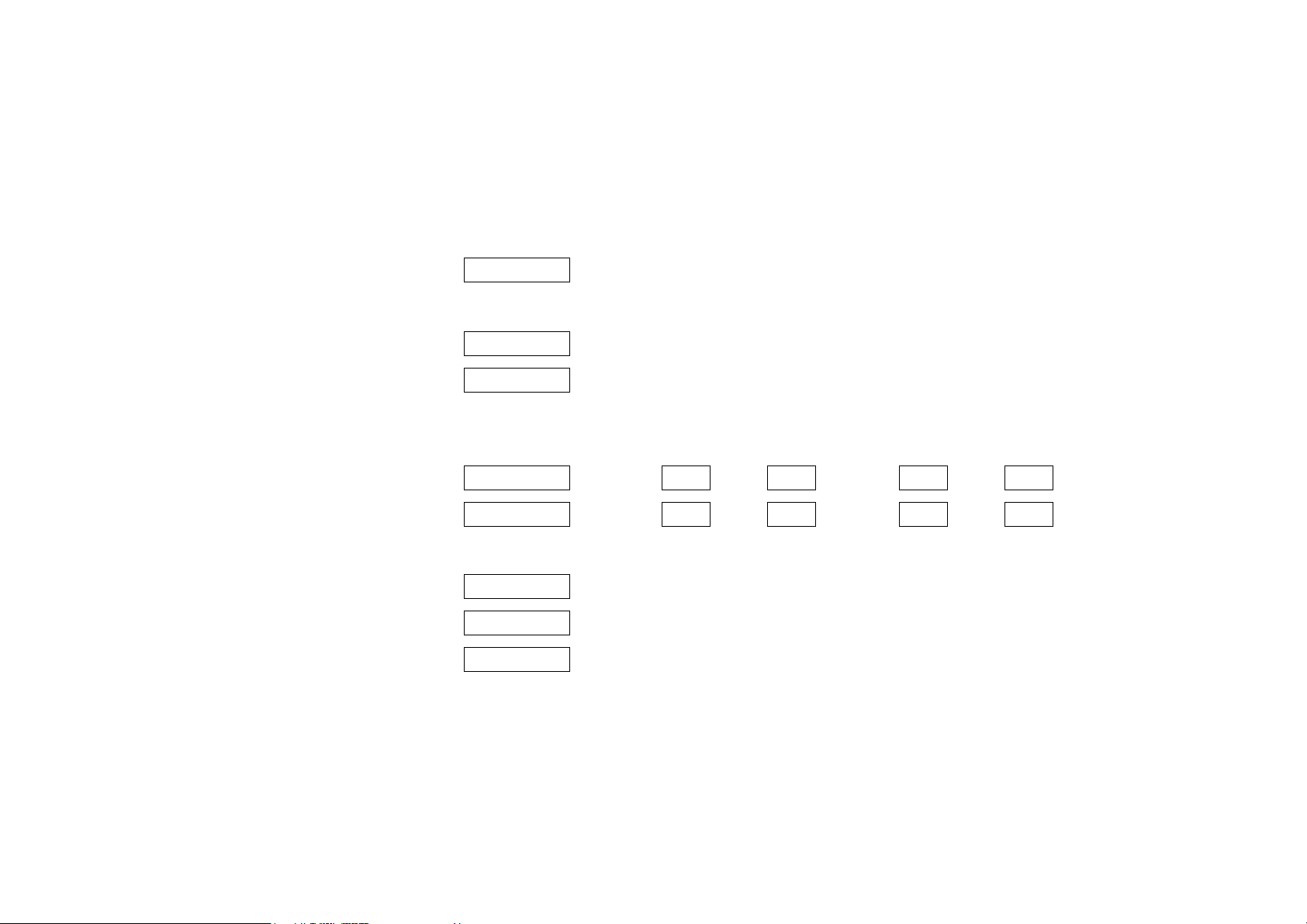
To unlock and open the luggage
compartment:
Press button q on remote control
and pull catch beneath handle
6 Remote control – see page 28, central
locking – see page 30,
Vauxhall alarm system 3 – see page 35.
Page 8
3In brief
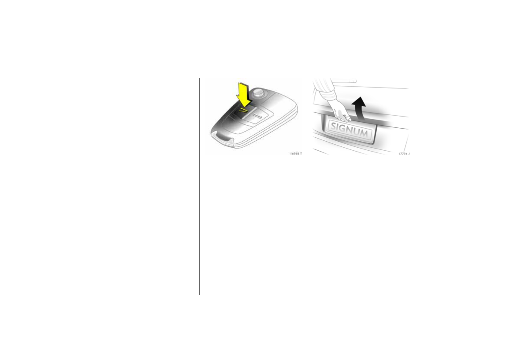
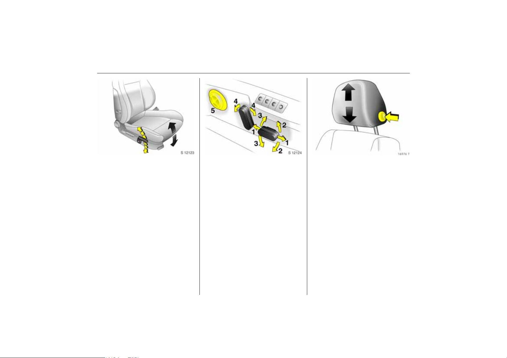
To adjust front seats:
Pull handle, slide seat,
release handle
6 Seats – see page 48,
seat position – see page 50,
electrically adjustable front seats –
see page 50,
adjusting rear seats – see page 56.
9 Warning
Important: Do not sit nearer than 10
inches (25 cm) from the steering wheel, to
permit safe airbag deployment.
To adjust front seat backrests:
Turn handwheel
Move backrest to suit seating position.
Do not lean on seat backrest whilst
adjusting it.
6 Seats – see page 48,
seat position – see page 50,
folding over front passenger seat
backrest – see page 67,
electrically adjustable front seats –
see page 50,
adjusting rear seats – see page 56.
To adjust front seat height 3:
Operate lever on outboard side of
seat
Pump action of lever
Upwards: Seat higher
Downwards: Seat lower
6 Seats – see page 48,
seat position – see page 50,
electrically adjustable front seats
– see page 50.
Page 9
4 In brief
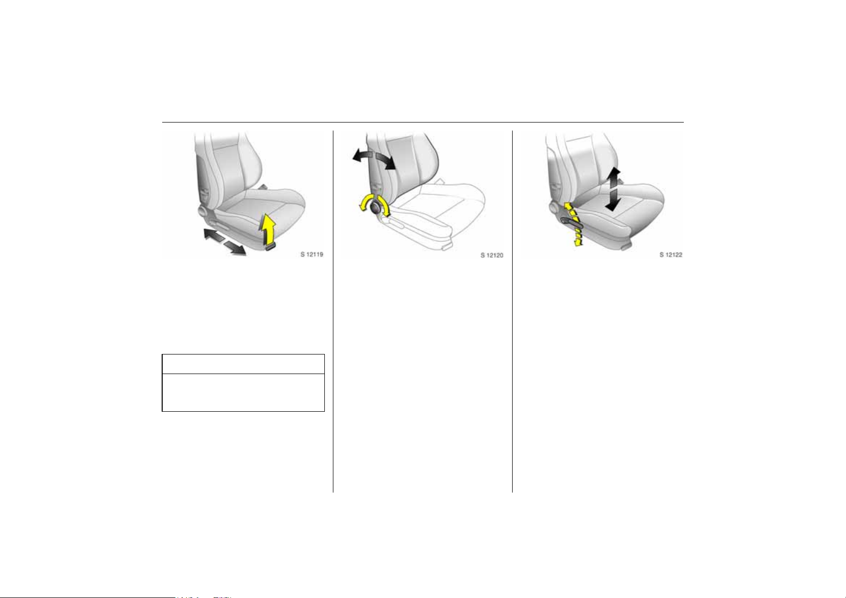
Adjusting front seat inclination 3:
Operate front lever on outboard
side of seat
Pump action of lever
Upwards: Seat steeper
Downwards: Seat flatter
6 Seats – see page 48,
seat position – see page 50,
electrically adjustable front seats –
see page 50.
Electric seat adjustment 3:
Operate switch on outboard side
of seat
1 Adjusting the longitudinal position
2 Adjusting the inclination
3 Height adjustment
4 Seat backrest adjustment
5 Lumbar support 3
6 Seats – see page 48,
seat position – see page 51,
electrically adjustable front seats –
see page 50.
To adjust head restraint height of
front and rear outboard seats 3:
Press button to release,
adjust height,
engage in position
6 Head restraints – see page 53,
head restraint position – see page 55,
adjusting centre rear head restraint –
see page 55.
Page 10
5In brief
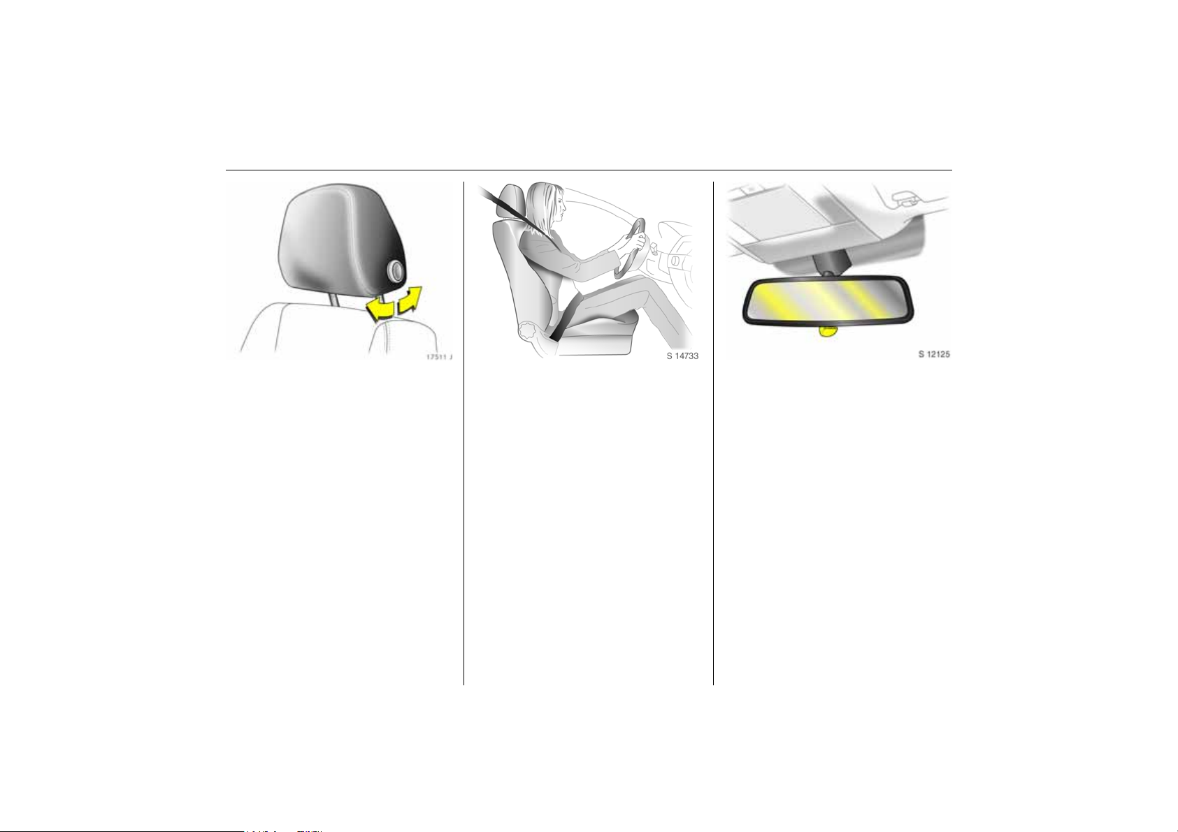
To adjust head restraint angle of
front and outboard rear seats 3:
Swivel bottom edge of head
restraint forward or rearward
6 Head restraints – see page 53,
head restraint position – see page 54,
rear head restraints – see page 54.
To put on seat belt:
Pull out seat belt without
jerking it, pass it over
the shoulder and click into
the belt buckle
The seat belt must not be twisted at any
point. The lap belt must lie snugly against
the body. The backrests must not be tilted
back too far (recommended maximum
tilting angle approx. 25 °).
To release belt, press red button on belt
buckle.
6 Three-point seat belts – see page 71,
airbag systems 3 – see page 81,
seat position – see page 50.
Adjusting interior mirror:
Swivel mirror housing
Swivel lever on underside of mirror housing
to reduce dazzle at night.
6 Mirror – see page 41,
automatic anti-dazzle interior mirror – see
page 41.
Page 11
6 In brief
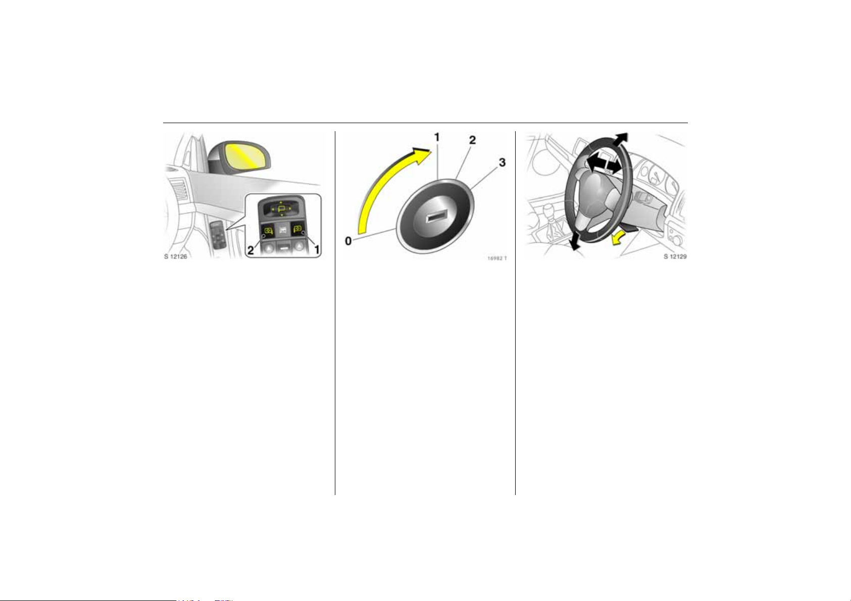
To adjust exterior mirrors:
Four-way switch in driver’s door
If the outer mirror switch is pressed 1 the
four-way switch operates the driver and
front passenger mirrors 3, and if the inner
mirror switch is pressed 2 it only operates
the front passenger mirror.
6 Mirrors – see page 40,
aspherical exterior mirrors 3 – see page 40,
automatic anti-dazzle exterior mirrors –
see page 41,
heated exterior mirrors – see page 13,
electric seat adjustment 3 – see page 50.
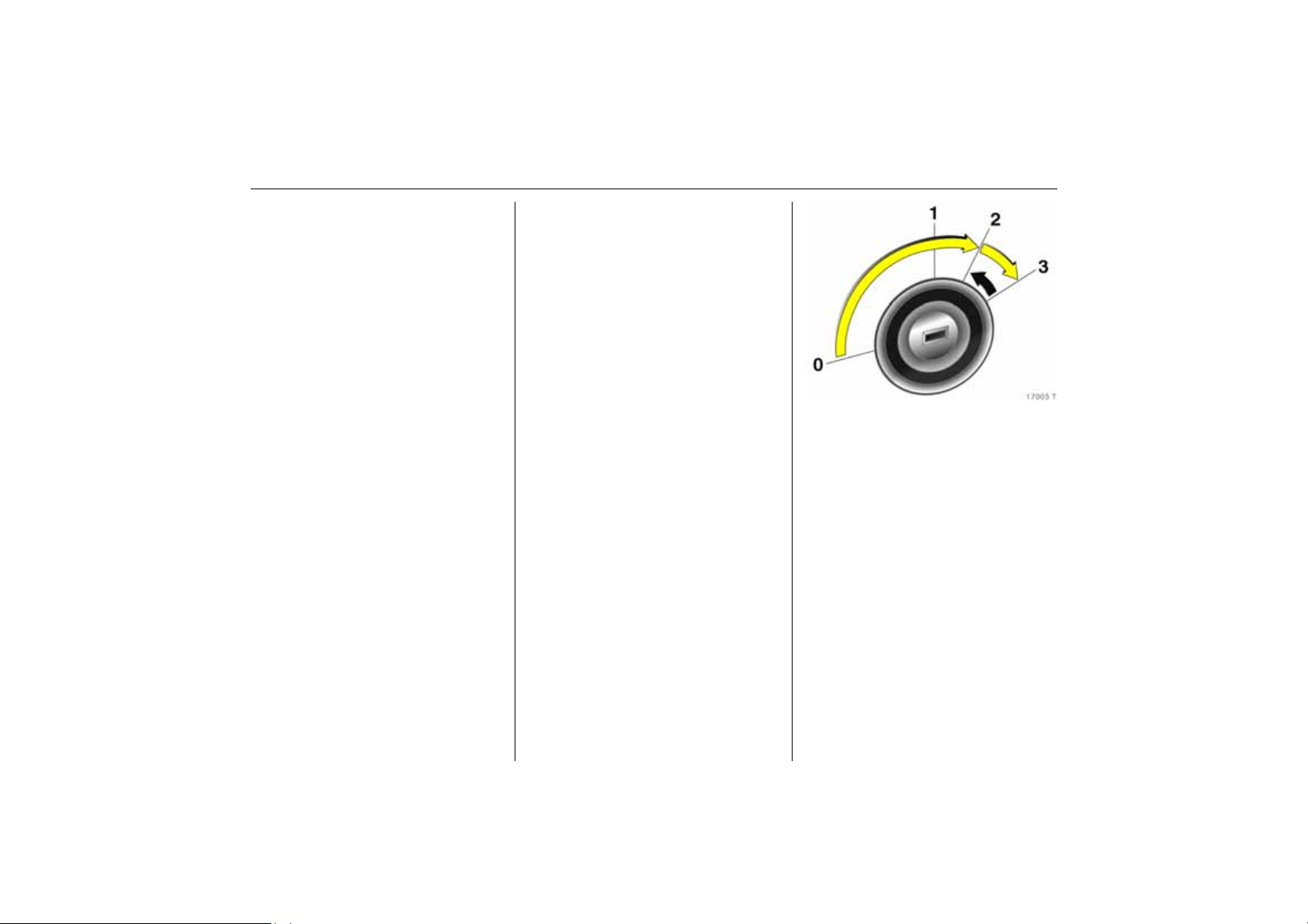
Steering column lock and ignition:
Turn key to position 1;
move steering wheel a little to
release steering lock
Positions:
0 = Ignition off
1 = Steering free, ignition off
2 = Ignition on, for diesel engine:
preheating
3=Starting
6 Starting – page 15,
electronic immobiliser – page 27,
parking the vehicle – page 16.
Steering wheel adjustment 3:
Move lever down,
adjust height and distance,
move lever up,
engage
Adjust steering wheel only when vehicle is
stationary and steering column lock is
released.
6 Airbag systems 3 – see page 81.
Page 12
7In brief
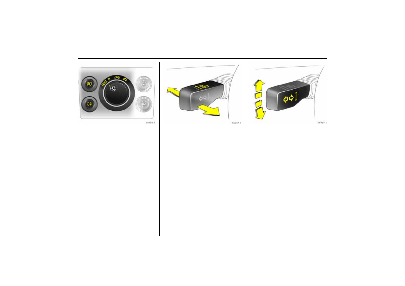
Turn light switch:
7 =Off
8 = Parking lights
9 = Dipped or main beam
AUTO = Automatic dipped
beam activation
3
Push button:
> =Fog lights 3
r = Fog tail light
6 Lighting – see page 128,
headlight control indicator
– see pages 16, 126.
Headlight flash, main beam and
dipped beam:
Headlight
flash = Pull stalk
towards
steering wheel
Main beam = Stalk forwards
Dipped beam = Lever forward
again or toward
steering wheel
6 Main beam, headlight flash
– see page 129.
Switch on turn signal lights:
Right = Stalk up
Left = Stalk down
6 Turn signal – see page130.
Page 13
8 In brief
Page 14

9In brief
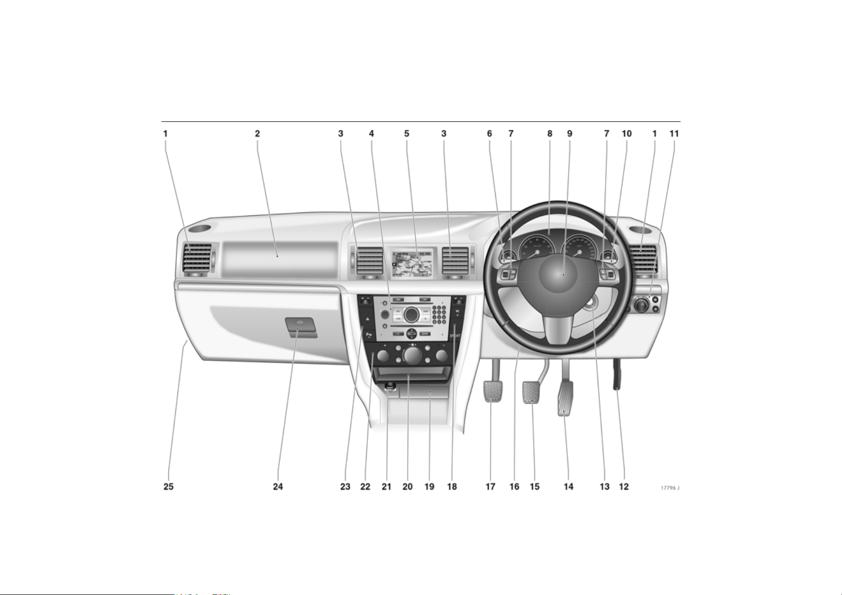
1 Side air vents .................................. 142
Page
2 Front passenger airbag .................. 81
3 Centre air vents ............................. 142
4 Infotainment system 3 ................. 137
5 Central information display for
time, date, outside temperature
Infotainment System 3,
Check-Control 3,
Trip computer 3,
Automatic air conditioning 3 ...... 108
6 Turn signal lights................................. 7
Headlight flash,
Dipped beam, main beam ................ 7
Door-to-door light function 3 .......133
Parking lights ................................. 134
Cruise control 3 .............................. 200
7 Steering wheel remote control 3 ..137
8 Instruments ....................................... 98
9 Horn .................................................. 11
Driver’s Airbag ................................ 81
10 Windscreen wiper,
Page
Windscreen wash system,
headlight wash system 3 and
rear window wash system 3 ........... 12
11 Parking lights, dipped beam ........ 128
Instrument illumination ................. 134
Fog tail light ................................... 131
Fog lights 3 .................................... 130
Headlight range adjustment 3 ..... 131
12 Unlocking the bonnet .................... 226
13 Ignition lock with steering
column lock ....................................... 6
14 Accelerator pedal ......................... 184
15 Brake pedal ........................... 185, 208
16 Steering wheel adjustment .............. 6
17 Clutch pedal 3............................... 185
18 Right heated seat 3 and
seat climate control 3 ................... 144
Vauxhall alarm system 3 ............... 35
SPORT mode 3 ............................. 198
19 Ashtray 3 ........................................ 95
20 Stowage compartment
Page
with AUX input 3 .......................... 138
21 Cigarette lighter 3 or socket 3 ...... 94
22 Climate control ............................. 140
23 Heated seat (left) 3 or
seat climate control 3 .................. 144
Hazard warning lights ................... 11
Parking distance sensor 3 ........... 202
24 Glove compartment ............... 96, 143
25 Fuse box ......................................... 243
Page 15

10 In brief
Control indicators
O
I
R
p
v
W
8
1
T
(
j
Turn signal lights,
see pages 7, 98.
Engine oil pressure,
see page 98.
Brake system, clutch system,
see pages 99, 208, 272.
Alternator,
see page 99.
Airbag systems, belt tensioners,
see pages 72, 81.
Coolant temperature,
see pages 100, 106.
Exterior lights,
see pages 100, 128.
Sport program of automatic
transmission 3,
see pages 171, 178.
Winter program of automatic
transmission 3 or Easytronic 3,
see pages 172, 180.
Door open 3,
see page 100.
Easytronic 3, starting the
engine 3,
see page 169.
t
s
>
C
r
r
u
X
A
!
H Coolant level,
Bulb replacement 3,
see pages 100, 249.
Open luggage compartment,
see pages 34, 101.
Fog lights 3,
see pages 101, 130.
Main beam,
see pages 7, 101.
Fog tail light,
see pages 101, 130.
Parking distance sensor 3,
fault,
see page 202.
Continuous Damping Control 3,
fault,
see page 198.
Seat belt 3,
see page 101.
Engine electronics, immobiliser,
transmission electronics 3,
diesel fuel filter 3, fault,
see pages 101, 182, 192.
Preheating system 3,
diesel particle filter 3,
see page 102.
see pages 102, 271.
u
p
v
y
S Engine oil level,
m
Y
Z
w
B
Anti-lock Braking System,
see page 210.
Electro-hydraulic power
assisted steering, fault,
see page 103.
Electronic Stability Program
Plus
(ESP®
see page 196.
Seat occupancy recognition 3,
see page 87.
see pages 103, 268.
Cruise control 3,
see page 200.
Fuel level,
see pages 103, 106, 189.
Exhaust gases 3,
see pages 104, 192.
Tyre pressure monitoring
system 3,
see pages 104, 204.
Adaptive Forward Lighting
(AFL) 3, fault,
see pages 104, 132.
) 3,
Page 16
11In brief
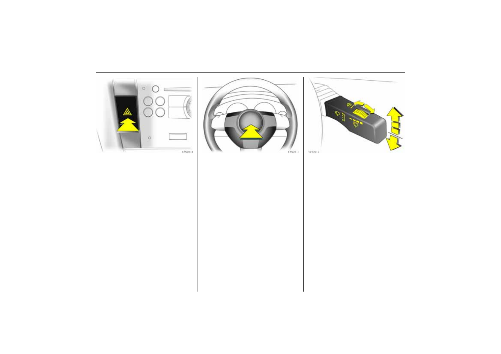
Hazard warning lights:
On = Press ¨
Off = Press
6 Hazard warning lights – page 131.
¨ again
To operate horn:
Press j in middle of steering
wheel
6 Airbag systems 3 – see page 81,
remote control from steering wheel 3 –
see page 137.
Windscreen wiper:
Gently tap lever upwards
§ =Off
$ = Adjustable timed interval
wipe
% =Slow
& =Fast
Press the stalk down from position §:
Single swipe.
6 Windscreen wipers – see page 126,
adjustable wipe interval 3 – see page 126,
wiper blades – see pages 273, 274,
car care – see page 260.
Page 17
12 In brief
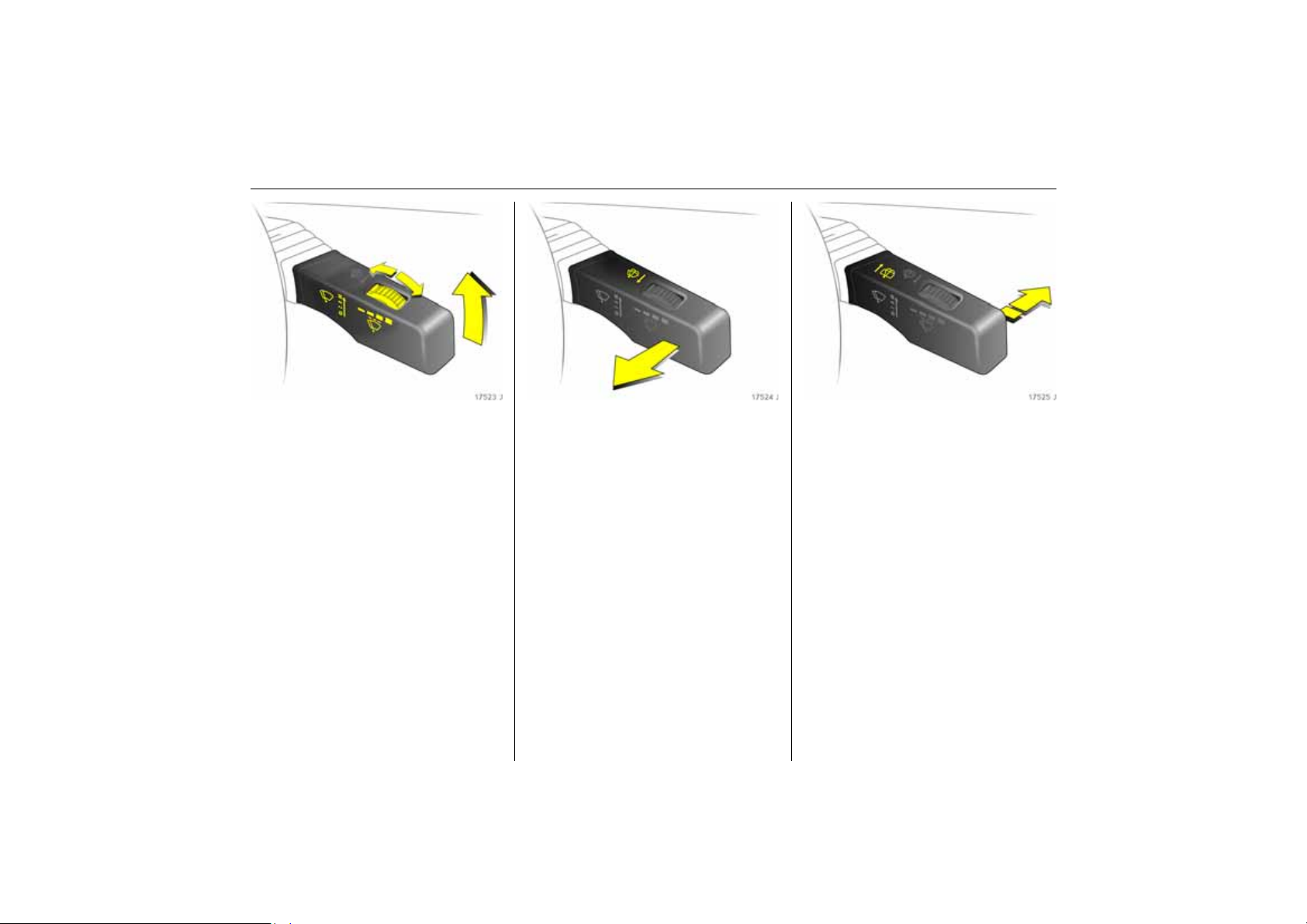
Automatic wiping with rain
sensor 3:
Gently tap stalk upwards
$ = Automatic wiping with
rain sensor
§ =Off
Automatic wiping $:
Low sensitivity: To the left
High sensitivity: To the right
6 Windscreen wiper – see page 126,
wiper blades – see pages 273, 274,
car care – see page 260.
Operating windscreen and
headlight wash systems 3:
Pull stalk towards steering wheel
6 Windscreen wash system and headlight
wash system – see page 127, further notes
– see pages 260, 273.
Operating rear screen wiper 3
and wash system 3:
Wipers on = Stalk forwards
Wipers off = Stalk forwards
again
Washing = Hold stalk pushed
fully forwards
6 Rear screen wash/wipe system
– see page 127,
further notes – see pages 260, 273.
Page 18
13In brief
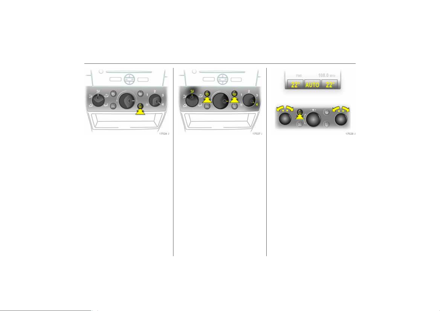
Heated rear window,
heated exterior mirrors:
On = Press Ü
Off = Press Ü again
6 Air conditioning – see page 140,
heated rear window – see page 143.
To demist or defrost windows:
Set air distribution to l,
rotary switch for temperature and
air flow clockwise;
Air conditioning system 3:
Press buttons n and V;
Automatic climate
control system 3:
Press buttons n and V,
turn rotary switch for
temperature clockwise,
air flow to A;
Climate control system 3:
Press button V
6 Climate control – see page 140.
Setting automatic mode of
climate control system 3:
Press AUTO button,
set temperature for driver and
passenger sides using left and
right rotary knobs
6 Climate control system 3 – see page 156.
Page 19
14 In brief
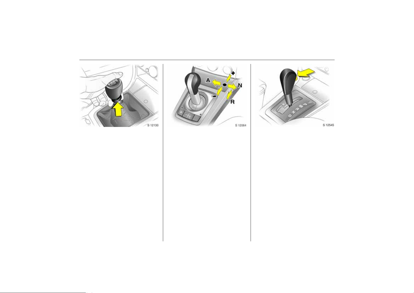
Manual transmission:
Reverse gear: with vehicle stationary, pull
the ring up three seconds after
de-clutching and engage gear.
If the gear does not engage, set the lever in
neutral, release the clutch pedal and
depress again; then repeat gear selection.
Easytronic 3:
N=Idling
o = Drive position
+ = Higher gear
-=Lower gear
A/M = Switch between
automatic and manual
mode
R=Reverse gear (with
selector lever lock)
The selector lever must always be moved in
the appropriate direction as far as it will
go. Upon release, it automatically returns
to the centre position. Pay heed to the
gear/mode indicator in the transmission
display.
The foot brake must be depressed when
starting.
6 Easytronic 3 – see page 168.
Automatic transmission 3:
P=Park position
R = Reverse gear
N = Neutral position (idling)
D = Automatic gear selection
Selector lever in D to the left:
Manual mode
+ = Higher gear
- = Lower gear
P or N must be engaged when starting.
Page 20
15In brief
In order to leave P switch on ignition,
operate foot brake and press button on
selector lever.
To engage P or R, push button on selector
lever.
P Only with vehicle stationary, apply
handbrake beforehand
R Only if vehicle is stationary
6 Automatic transmission 3 – see
page 176.
Before starting off, check:
z Tyre pressure and condition – see
pages 204, 211, 288.
z Engine oil level and fluid levels in engine
compartment – see pages 267 to 275.
z All windows, mirrors, exterior lighting
and number plates are free from dirt,
snow and ice and operational.
z Do not place any objects in front of the
rear window, on the instrument panel or
in the area in which the airbags inflate.
z Seats, seat belts and mirrors are
correctly adjusted.
z Brake function.
To start engine:
Operate clutch and brake,
automatic transmission 3
in P or N,
Easytronic 3: Depress brake,
do not accelerate;
Petrol engine: Turn key to 3;
Diesel engine: Turn key to 2,
when control indicator !
goes out1), turn key to 3;
release key once engine is
running
To restart or switch off the engine, turn key
back to 0.
To switch on the ignition, only turn the key
to 2.
6 Electronic immobiliser – see page 27,
diesel fuel system – see page 226.
1)
Preheating system switches on only if outside
temperature is low.
Page 21
16 In brief
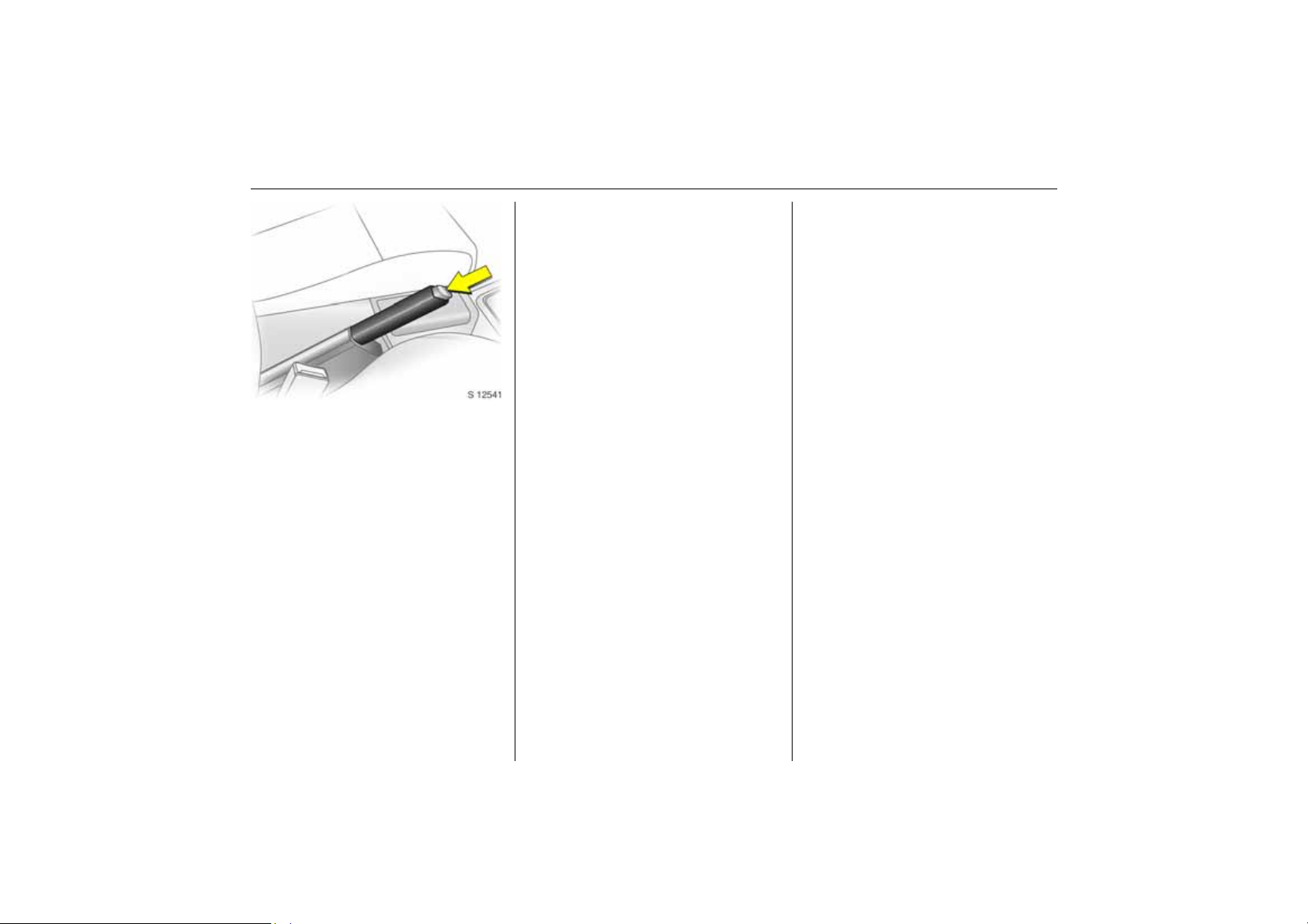
Releasing the hand brake:
Raise lever slightly,
press release button,
lower lever fully
6 Handbrake – see page 209.
Parking the vehicle
z Always apply the handbrake firmly
without actuating the release knob; to
do this fold up the armrest 3. Apply as
fully as possible on an uphill or downhill
incline. To reduce the amount of force
required to activate the brake, depress
the foot brake at the same time.
z Switch off the engine - to do this, turn the
ignition key to 0. Remove the ignition key
and turn the steering wheel until the
steering lock (anti-theft protection)
engages. In cars with automatic
transmission 3, the key can only be
removed when the selector lever is in P.
z If the vehicle is on the flat or an uphill
incline engage first gear before
switching off the ignition if you have
manual transmission or Easytronic 3;
if the vehicle has automatic
transmission 3, place the selector
lever in P. On an uphill incline also turn
the front wheels away from the kerb.
If the vehicle is on a downhill incline,
engage reverse gear before switching off
the ignition if you have manual
transmission or Easytronic 3; if the
vehicle has automatic transmission 3,
place the selector lever in P. Also turn the
front wheels towards the kerb.
z Lock the doors and luggage
compartment by pressing button p on
the remote control. To activate the
anti-theft locking system 3 and
anti-theft warning system 3, press
button p twice.
Advice when parking:
z Do not park vehicle on easily ignitable
surfaces, since the hot exhaust system
temperatures could cause the surface to
ignite.
z On vehicles with Easytronic 3 control
indicator R flashes for a few seconds
after the ignition is switched off if the
hand brake has not been applied – see
page 174.
z Closing windows and sun roof 3.
z The engine cooling fans may run after
the engine has been switched off – see
page 267.
6 Remote control – see page 28, central
locking – see page 30,
Vauxhall alarm system 3 – see page 35,
vehicle decommissioning – see page 277.
Page 22

That was a brief overview of the
most important information for
your first trip in your vehicle.
The other pages of this chapter
contain a summary of the
interesting functions in your
vehicle.
The remaining chapters of the
Owner’s Manual contain
important information on
operation, safety and
maintenance as well as a
complete index.
17In brief
Page 23
18 In brief
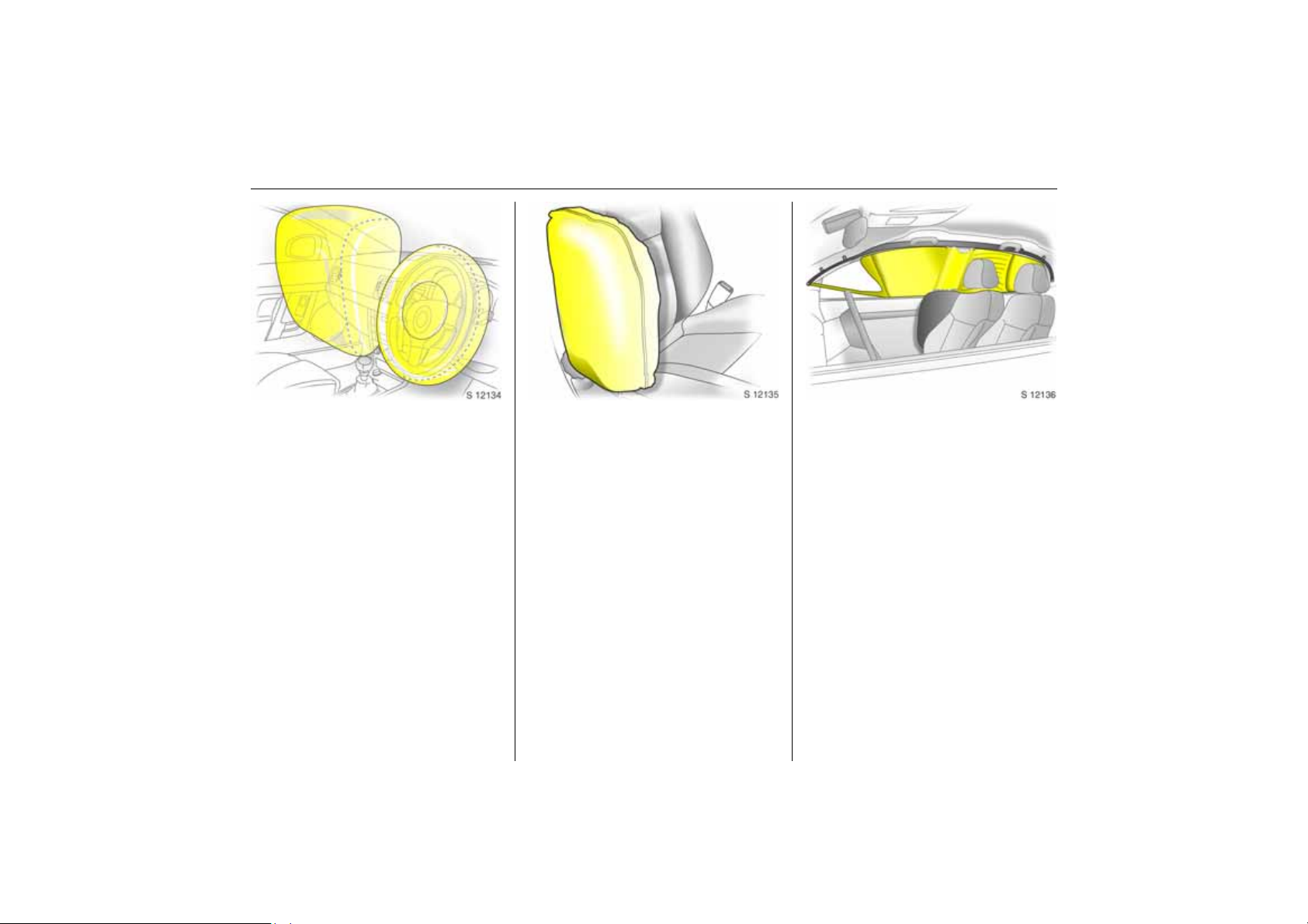
Airbag System
The airbag system consists of several
separate systems.
Front airbag system
The front airbag system will be triggered in
the event of a serious accident involving a
frontal impact and forms safety cushions
for the driver and front passenger. The
forward movement of the driver and front
passenger is checked and the risk of
injuries to the upper body and head
thereby substantially reduced.
Side airbag system 3
The side airbag system triggers when a
side-on collision occurs and provides a
safety barrier for the driver and/or
passenger in the respective front door
area. This reduces the risk of injury to the
upper body considerably in case of a side
impact.
Curtain airbag system 3
The curtain airbag system triggers in case
of a side-on collision and provides a safety
barrier in the head area on the respective
side of the vehicle. This reduces the risk of
injury to the head considerably in case of a
side-on collision.
6 Airbag systems 3 – see page 80.
Page 24
19In brief
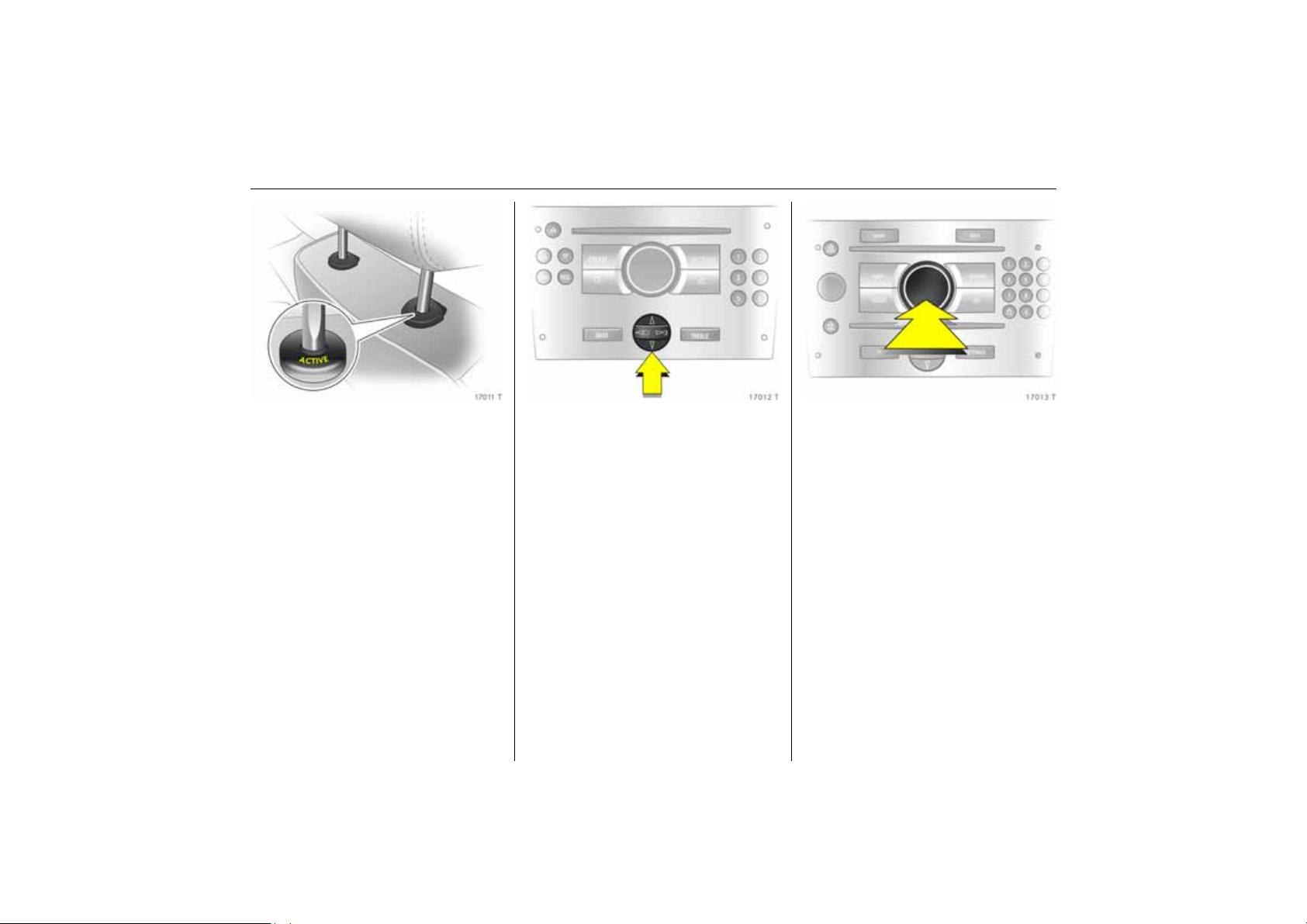
Active head restraints 3 at front
seats
In the event of a rear-end impact, the
active head restraints tilt forward a little.
The head is more effectively supported by
the head restraint and the danger of
injuries caused by whiplash in the area of
the neck is reduced.
Active head restraints are identified by the
lettering ACTIVE on the head restraint
guide sleeves.
6 Head restraints – see page 53.
Operating menus in the
information display 3
Menu options are selected using menus
and using the buttons/four-way button
or the multifunction button of the
Infotainment system 3 or the left-hand
adjuster wheel 3 on the steering wheel.
The respective menu options are shown on
the display.
To select with four-way button:
Press the four-way button up, down, right
or left.
Selection using multifunction button: rotate
and press multifunction button.
To exit a menu, turn the multifunction
button left or right to Return or Main and
select.
Page 25

20 In brief
Ü Board Computer 19,5° 19:36
BC 1 All values
BC 2
Timer
Tyres
1
8
257.0 miles
Ø40mph
11.0 gals
Ø 7.0 miles/gal
Coolant level
check
OK
Selection using left-hand adjuster wheel on
steering wheel: rotate and press adjuster
wheel.
6 Info Display – see page 108.
Trip computer 3
The trip computers provide information on
driving data, which is continually recorded
and evaluated electronically.
Functions:
z Range
z Instantaneous consumption
z Distance travelled
z Average speed
z Effective consumption
z Average consumption
z Stop watch
z Tyre pressure 3
6 Trip computer 3 – see pages 114, 120.
Check control 3
The check control software monitors
z Fluid levels
z Tyre pressure 3
z Remote control battery
z Vauxhall alarm system 3
z Important exterior lighting lights,
including cables and fuses.
6 Check control 3 – page 124.
Page 26
21In brief
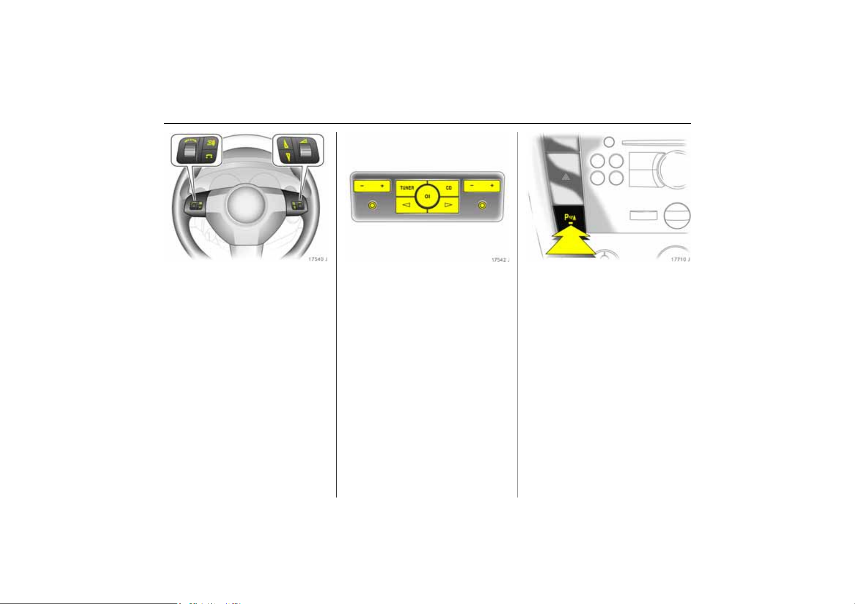
Remote control on steering
wheel 3
The functions of the infotainment system 3
and the information display can be
operated with the buttons and adjuster
wheels on the steering wheel.
Further information is available in the
infotainment system operating
instructions.
6 Remote control on steering wheel 3
– see page 137,
Infotainment system – see pages 108, 137.
Twin Audio 3
Twin Audio allows rear seat occupants the
choice between the audio source played on
the infotainment system or a separate
audio source.
Only an audio source that is not currently
active on the infotainment system can be
controlled using Twin Audio.
Two headphone connections are available,
with separate volume controls.
Further information is available in the
infotainment system operating
instructions.
6 Twin Audio 3 – see page 138.
Parking distance sensor 3
When reverse gear is selected, the parking
distance sensor switches itself on
automatically.
The parking distance sensor can also be
activated at speeds of less than 15 mph
(25 km/h) by pressing the
the instrument panel.
If the vehicle approaches an obstacle to
the front or rear, an series of signals is
sounded in the vehicle interior. The interval
between the signals becomes shorter as
the distance is reduced. If the distance is
less than 30 cm, the signal will be
continuous.
6 Parking distance sensor 3
– see page 202.
r button on
Page 27
22 In brief
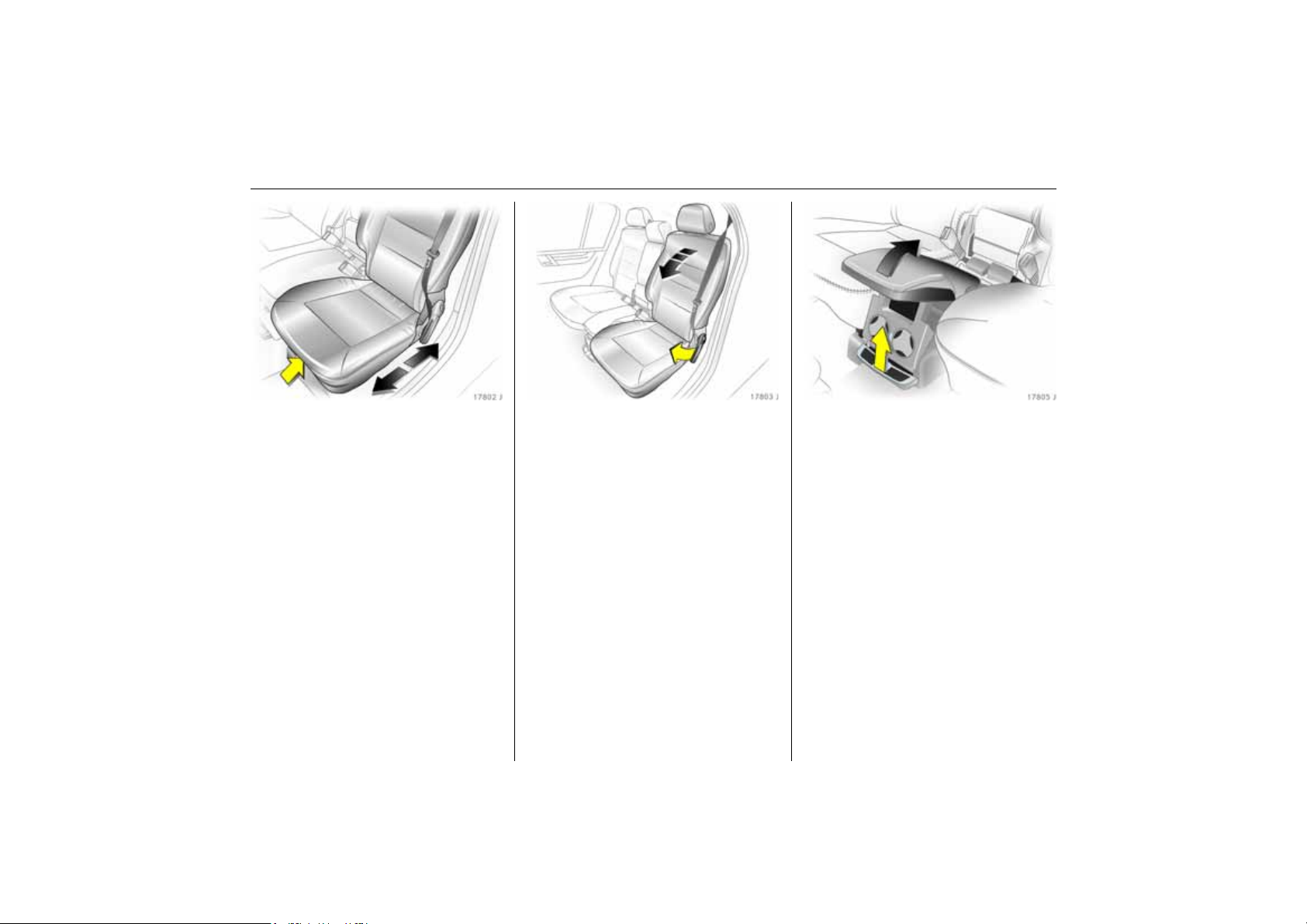
Rear seats
To adjust outboard seats
z Pull handle beneath seat.
z Slide seat forward or rearward.
z Release handle and audibly engage seat
in position.
To adjust or fold outboard seat backrest
z When folding the seat, guide the seat
belt through the side retainer.
z Pull handle on outboard side of seat.
z Adjust backrest forward or rearward or
until it engages on the seat cushion.
Folding the centre seat cushion
z Pull handle beneath seat.
z Raise the seat.
z Fold the seat rearward 180° until the
cushion points down.
6 Rear seats – see page 56.
Page 28
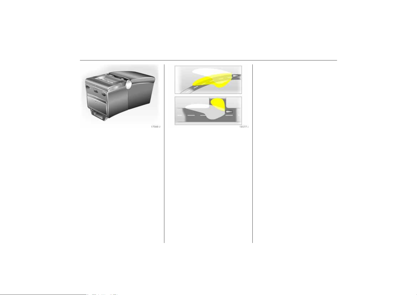
Travel Assistant 3
The Travel Assistant Contains
z Armrest
z Stowage compartments
z Waste container
z Drink holders
z Accessory sockets
z Connection console
e.g. for DVD-player 3
z Electric cool box
z Tables
z Twin Audio (rear audio module) 3 or
stowage compartment
The Travel Assistant is installed on a
console above the middle seat in the rear.
6 Travel Assistant 3 – see page 58.
Adaptive Forward Lighting
(AFL) 3
On vehicles with Bi-Xenon headlights,
improves illumination of
z curves (curve lighting)
z intersections and tight turns (turn
lighting)
23In brief
Curve lighting
The Xenon light beam pivots based on
steering wheel position and speed (from
approx. 6 mph /10 km/h).
The headlights shine at an angle of up
to 15° to the right or left of the direction of
travel.
Turn lighting
An additional light comes on at certain
steering wheel settings (after approx. 90°),
turn signal settings and speeds (up to
approx. 25 mph / 40 km/h).
The light beam projects at a 90° angle to
the left or right of the vehicle up to a
distance of approx. 30 metres.
Motorway lighting
At higher speeds and continuous straight
ahead travel, the dipped beam
automatically raises slightly, thereby
increasing headlight range.
6 Adaptive forward lighting 3
– see page 132.
Page 29
24 In brief
Damping and steering 3 become more
direct and provide better contact with the
road surface. The engine reacts more
quickly to accelerator movements.
With automatic transmission 3, the shift
times are reduced and gear changes occur
at higher engine speeds (not when cruise
control 3 is active).
6 Sport mode 3 – see page 198.
Ü Board Computer
BC 1
BC 2
Timer
Tyres
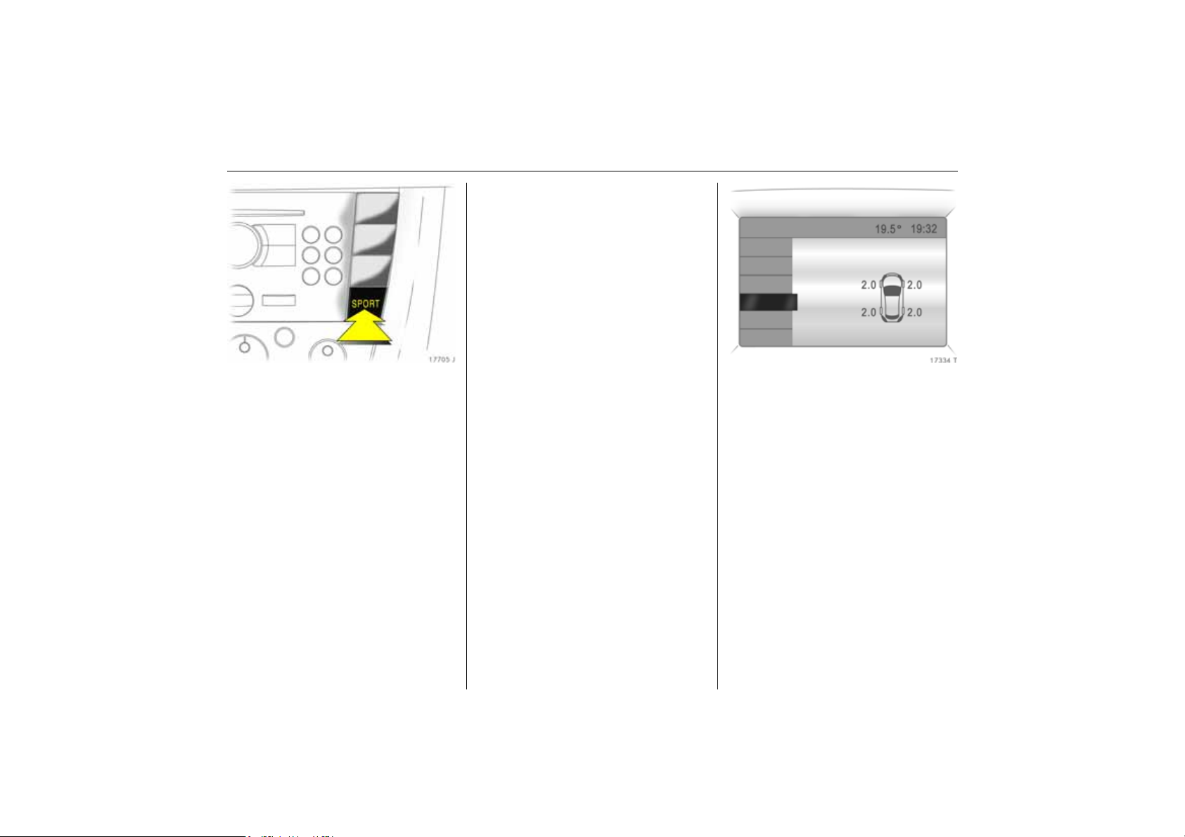
SPORT mode 3
To activate
Press the SPORT button. The LED in the
button illuminates.
SPORT mode is used to change
damping 3, steering 3, throttle application
and the shifting times and shifting points
for Easytronic 3 and automatic
transmission 3 while driving.
Tyre pressure monitoring
system 3
The tyre pressure monitoring system
continuously monitors the pressure of all
four tyres while the vehicle is being driven.
A pressure sensor is installed in each wheel.
The inflation pressures of the individual
tyres are transmitted to a controller, where
they are compared.
The current tyre pressures can be
displayed on the graphical information
display or the colour information display 3.
Deviating tyre pressures are displayed in
the form of messages on the information
display whilst driving.
6 Tyre pressure monitoring system 3 –
see page 204.
Page 30
Diesel particle filter 3
The diesel particle filter system removes
polluting soot particles out of the engine
exhaust gases. The system includes a
self-cleaning function that operates
automatically while driving. The filter is
cleaned by burning the trapped soot
particles at a high temperature. There may
be an increase in fuel consumption,
exhaust smell, and engine cooling fan
operation 3 during the self-cleaning
operation.
The self-cleaning function can not operate
automatically during certain driving
situations where the engine does not reach
its normal operating temperature. An
example of this would be driving only short
distances in cold weather.
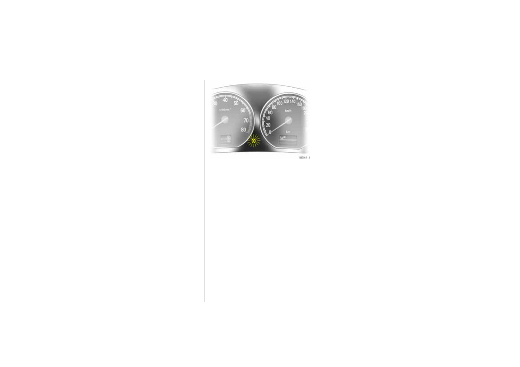
If the filter needs cleaning and recent
driving situations did not allow the function
to automatically operate, then the control
indicator
you may continue to drive the vehicle
normally. The vehicle will not be damaged
and does not require service.
The self-cleaning function will
automatically operate while driving after
the engine has reached its normal
operating temperature. The control
indicator
self-cleaning operation is complete. This
may take up to 20 minutes of driving. The
time will be shorter at higher vehicle
speeds.
6 Diesel particle filter – see page 194.
! will flash. If this occurs, then
! will continue to flash until the
25In brief
Page 31

26 Keys, doors, windows, sun roof
Keys, doors, windows,
sun roof
Replacement keys ............................... 26
Car Pass 3............................................ 26
Key with foldaway key section 3 ....... 26
Electronic immobiliser.......................... 27
Store and activate personal vehicle
settings using the remote control .... 28
Remote control .................................... 28
Central locking system ........................ 30
Fault when locking or unlocking......... 33
Luggage compartment....................... 34
Vauxhall alarm system 3.................... 35
Child safety locks................................. 37
Universal remote control in mirror
housing 3........................................... 38
Exterior mirrors..................................... 40
Interior mirror ....................................... 41
Electric windows................................... 42
Windows in rear doors ........................ 44
Sun roof 3 ............................................ 45
Roller blinds at rear door windows 3. 47
Replacement keys
The key number is specified in the vehicle
documents and in the Car Pass 3.
The key is a constituent of the electronic
immobiliser. Ordering keys from a Vauxhall
Authorised Repairer guarantees problemfree operation of the electronic
immobiliser.
Keep the spare key in a safe spot.
Locks, see page 262.
Car Pass 3
The Car Pass contains all of the vehicle’s
data and should therefore not be kept in
the vehicle.
Have your Car Pass on hand when
consulting a Vauxhall Authorised Repairer.
Key with foldaway key section 3
Press button to extend. Press button to
retract and audibly engage key section.
Page 32

27Keys, doors, windows, sun roof
If control indicator A illuminates after the
engine is started, there is a fault in the
engine electronics or transmission
electronics 3 (see pages 174, 182, 192) or
there is water in the diesel fuel filter 3, see
page 270.
Note
The immobiliser does not lock the doors.
Therefore, after leaving the vehicle always
lock it and switch on the Vauxhall alarm
system 3 – see pages 30, 35.
Electronic immobiliser
The system checks whether the vehicle may
be started using the key that has been
inserted. If the key is recognised as
"authorised" the vehicle can be started.
The check is carried out via a transponder
in the key.
The electronic immobiliser activates
automatically when the key is removed
from the ignition switch.
The code number of the electronic
immobiliser is given in the Car Pass.
Control indicator for immobiliser
Control indicator A illuminates briefly
when the ignition is switched on.
If the control indicator flashes when the
ignition is on, there is a fault in the system;
the engine cannot be started. Switch off
the ignition and then repeat the start
attempt.
If the control indicator A continues to
flash, try to start the engine using the
second key and contact a workshop for
assistance.
Page 33

28 Keys, doors, windows, sun roof
Store and activate personal
vehicle settings using the remote
control
The last settings selected for
z the instrument illumination,
z the central locking,
z the memory function 3 for driver’s seat
and mirror,
z the climate control system 3
are automatically stored depending on the
vehicle key used.
Different settings are stored for each
remote control. Use of a remote control will
activate the settings associated with it.
The settings for five remote controls can be
stored.
Remote control
The remote control is integrated in the key.
Used to operate:
z central locking system,
z mechanical anti-theft locking system 3,
z Vauxhall alarm system 3,
z tailgate,
In addition, electric windows 3 can be
closed using the remote control. The
electric sun roof 3 can be closed using the
remote control.
The remote control has a range of approx.
5 metres. This range can be affected by
outside influences. Aim the remote control
at the vehicle to operate.
Handle the remote control with care,
protect it from moisture and high
temperatures and avoid unnecessary
operation.
The hazard warning lights come on to
indicate that the remote control is
operational.
Central locking system,
see page 30.
Mechanical anti-theft locking system 3,
see page 30.
Tailgate,
see page 34.
Vauxhall alarm system 3,
see page 35.
Electric windows 3,
see page 42.
Electrically operated sun roof 3,
see page 45.
Page 34

29Keys, doors, windows, sun roof
Fault
If the central locking system cannot be
operated with the remote control, it may be
due to the following:
z The range of the remote control has
been exceeded.
z Remote control battery voltage is too
low. Battery replacement - see next
page.
z Frequent, repeated operation of the
remote control outside the reception
range of the vehicle (e.g. too far from
vehicle, remote control is then no longer
recognised). Remote control
synchronisation – see next page.
z If the central locking system is
overloaded as a result of repeated
operation at short intervals. The power
supply is cut off for a brief period.
z Interference from higher-power radio
waves from other sources.
To eliminate the cause of a fault, we
recommend contacting a workshop for
assistance.
Manual unlocking and locking using the
vehicle key, see page 33.
Make sure that you dispose of old batteries
in accordance with environmental
protection regulations.
Remote control synchronisation
After a battery change, unlock door with
key in lock, see page 33. Inserting the key
into the lock synchronises the remote
control.
Remote control battery replacement
Replace the battery as soon as the range
of the remote control begins to shrink.
Extending the key – see page 26.
Open the remote control. Replace the
battery (battery type – see page 293),
noting installation position. Close the
remote control.
Page 35

30 Keys, doors, windows, sun roof
Central locking system
For doors, boot lid/tailgate and tank flap.
To unlock
Press button q on remote control.
To lock
Press button p on remote control.
Mechanical anti-theft locking system 3
9 Warning
Do not use the system if there are people
in the vehicle! The doors cannot be
unlocked from inside.
All doors must be closed. Press button p
on remote control again no more than
15 seconds after locking.
Lock buttons on all doors are positioned
such that doors cannot be opened.
If the ignition was on, the driver’s door
must be opened and closed once so that
the vehicle can be secured.
Page 36

31Keys, doors, windows, sun roof
Programming unlocking mode
When the vehicle is delivered from the
factory, the remote control is preset so that
a single press of the q button opens all of
the doors and the luggage compartment.
The unit can be configured so that a single
press of the q button unlocks the entire
vehicle or just the driver’s door.
Change to presetting:
Hold button q on the remote control and
m in the driver’s door depressed
button
simultaneously until a double buzzer
sounds. Afterwards, only the driver’s door
will be unlocked when button q is pressed
once.
The entire vehicle is then unlocked by
pressing button q on the remote control
twice.
To restore the original settings, hold
button q of the remote control and
m in the driver’s door depressed
button
simultaneously until a buzzer sounds.
The current setting is stored for the remote
control, see page 28.
Central locking switch for locking and
unlocking the doors from inside the
vehicle
Press button
m in the driver’s door: Doors
and luggage compartment are locked.
Press button
) in the driver’s door: Doors
and luggage compartment are unlocked.
When the mechanical anti-theft locking
system is active 3, see page 30, the doors
cannot be unlocked with this button.
If the vehicle is locked using the remote
control, buttons
m and ) in the driver’s
door are inoperable.
Automatic locking 3
The central locking can be set to lock
automatically at a certain speed.
To activate the function, hold button p of
the remote control and button
m in the
driver’s door depressed simultaneously
until a double buzzer sounds.
The doors and luggage compartment are
unlocked by switching off the ignition or by
pressing button
) in the driver’s door.
Individual doors can be unlocked by
pulling on the lock button.
To deactivate the function, hold button p
of the remote control and button
m in the
driver’s door depressed simultaneously
until a buzzer sounds.
The current setting is stored for the remote
control, see page 28.
Page 37

32 Keys, doors, windows, sun roof
Note
z If the driver’s door is not closed properly,
the central locking system will unlock
again immediately after locking.
z 30 seconds after unlocking using the
remote control the doors automatically
lock again 3 if neither a door nor the
luggage compartment has been
opened.
z To lock the doors from within (e.g. to
prevent undesired access from outside),
press the central locking switch
z If they are locked, the doors and the
luggage compartment unlock
automatically in the event of an accident
of a certain severity (to permit outside
assistance). Prerequisite: Ignition must
not be switched off.
m.
Closing the windows and sun roof 3 from
outside
9 Warning
Take care when operating the electric
windows and the sun roof 3. Risk of
injury, particularly to children.
Vehicle passengers should be informed
accordingly.
Keep a close watch on the windows and
sun roof 3 when closing them. Ensure
that nothing becomes trapped in them as
they move.
In vehicles with electronic windows, the
windows can be closed from outside: hold
down button p on the remote control until
all windows are closed.
The sun roof 3 can be closed from outside:
hold down button p on the remote control
until the roof is fully closed.
Vehicle with electrically retractable exterior
mirrors 3: When closing the windows using
the remote control, the exterior mirrors will
also be retracted. The mirrors will be folded
back out when the vehicle is unlocked using
the remote control.
If the mirrors are retracted using the button
in the driver’s door, they remain in this
position when the doors are unlocked.
Page 38

33Keys, doors, windows, sun roof
Automatic closing 3
If the mechanical anti-theft locking
system 3 is activated, the electronic
windows and sun roof 3 are automatically
closed and the electrically retractable
exterior mirrors 3 are automatically
retracted as soon as the rain sensor 3
detects water on the windscreen.
To safeguard the battery from discharge
by the rain sensor 3, after four hours the
windows and sun roof 3 are automatically
closed and the electrically retractable
exterior mirrors 3 are automatically
retracted.
For further information on windows and
the sun roof – see pages 42, 45.
Fault
If the central locking system cannot be
operated with the remote control, it may be
due to the following:
z If the central locking system is
overloaded as a result of repeated
operation at short intervals. The power
supply is cut off for a brief period.
z Defective fuse in fuse box – see
page 243.
Seek the assistance of a workshop to rectify
the cause of the fault. To open the driver’s
door with the key, see the following section.
Fault when locking or unlocking
Remote control fault
To unlock
Insert key into lock in driver’s door and turn
forwards as far as it will go. Turn key back
to vertical position and remove from lock.
Unlock driver’s door with central locking
switch, see page 31.
The mechanical anti-theft locking system 3
is deactivated when the key is inserted in
the ignition switch.
To lock
Open front passenger door, close driver’s
door, lock vehicle using central locking
switch, see page 31, close front passenger
door.
Malfunction in central locking system
To unlock
Insert key into driver’s door lock and turn
forwards as far as it will go. Turn key back
to a vertical position and remove. The
other doors can be unlocked by pulling the
interior lock button (unless the mechanical
anti-theft locking system has been
enabled 3). The luggage compartment
and the fuel filler cap remain locked.
To lock
Lock front passenger door and rear doors
by pushing the interior lock button. Lock
driver’s door with key in lock. Turn key
towards rear of vehicle as far as it will go,
turn key to a vertical position and remove.
The unlocked fuel filler cap and the
luggage compartment cannot be locked.
Page 39

34 Keys, doors, windows, sun roof
Luggage compartment
To unlock
Press button q on remote control.
To open
The luggage compartment can be opened
by pulling the catch beneath the handle.
Illumination of
luggage compartment is open.
Pay attention to instructions concerning
open tailgate, see page 35.
s indicates the the
To close
There is a handle on the inside of the
tailgate for closing the luggage
compartment.
Page 40

To lock
Press button p on the remote control
– or –
central locking switch
press when doors are closed.
Open tailgate
m in driver’s door -
9 Warning
Do not drive with the luggage
compartment open, e.g. when
transporting bulky objects, since toxic
exhaust gas could penetrate the interior.
Also, the number plate cannot be clearly
read unless the luggage compartment is
closed.
Vauxhall alarm system 3
Monitors
z the doors, luggage compartment,
bonnet,
z the passenger compartment,
z vehicle tilt, e.g. if it is raised,
z the ignition.
9 Warning
Do not use the system if there are people
in the vehicle! The doors cannot be
unlocked from the inside.
35Keys, doors, windows, sun roof
To activate
All doors, windows, the sun roof 3 and the
bonnet must be closed. Within no more
than10 seconds of locking, press button p
on the remote control again.
If the ignition was switched on, the driver’s
door must be opened and closed again so
that the Vauxhall alarm system can be
activated again.
Fitting of accessories on the tailgate will
increase its weight. If it becomes too heavy,
the tailgate will then not stay open.
Page 41

36 Keys, doors, windows, sun roof
After the first 10 seconds of the Vauxhall
alarm system activation:
z LED flashes
slowly
z LED comes
on for approx.
1 second
If a system fault occurs, contact a
workshop for assistance.
=System switched on
= Switch-off function
Activation without monitoring of
passenger compartment and vehicle tilt
Activate e.g. when animals are left in the
vehicle.
1. Close tailgate and bonnet.
2. Press button Ä, LED in button flashes
(maximum of 10 seconds), see next
column.
3. Close doors.
4. Switch on the Vauxhall alarm system.
LED illuminates. After approx. 10
seconds the system is activated, without
monitoring of the passenger
compartment or vehicle tilt. LED flashes
until system is switched off.
Light emitting diode (LED)
During the first 10 seconds of the Vauxhall
alarm system activation:
z LED comes on
z LED flashes
quickly
= Test, switch-on delay
= Door, luggage
compartment, open
bonnet or system
faults
Page 42

To deactivate
Press button q of the remote control
– or –
turn on the ignition.
If there is a fault in the remote control,
unlock vehicle as described on page 33.
If the alarm is triggered when the driver’s
door is opened, deactivate the Vauxhall
alarm system by switching on the ignition.
Note
z Changes to the vehicle interior, such as
the use of seat covers, could impair the
function of passenger compartment
monitoring.
z Disable interior monitoring if the interior
of the vehicle switched off is being
heated.
Alarm
An alarm can be triggered whilst the
Vauxhall alarm system is active:
z an acoustic signal (horn) and
z a visual signal (hazard warning lights).
The number of alarms and the duration
thereof are stipulated by law.
The alarm can be silenced by pressing a
button of the remote control or by
switching on the ignition. The Vauxhall
alarm system is deactivated at the same
time.
37Keys, doors, windows, sun roof
Child safety locks
9 Warning
Use the child safety lock whenever
children are occupying the rear seats.
Disregard may lead to injuries or
endanger life. Vehicle passengers should
be informed accordingly.
Turn rotary knob at rear door lock from the
vertical position using key: door cannot be
opened from inside.
Page 43

38 Keys, doors, windows, sun roof
Universal remote control in mirror
housing 3
to operate up to 3 different remotely
operated systems (e.g. garage door,
domestic alarm system, domestic exterior
lighting).
The programmed universal remote control
can replace the individual remote control
units of the systems to be operated. Three
buttons on the underside of the mirror
housing can be used to operate various
systems.
Consult your Vauxhall Authorised Repairer
for details on compatible systems.
9 Warning
Ensure that no persons, animals or
objects are in the movement zone of the
system to be operated (e.g. a garage
door). Vehicle passengers should be
informed of the hazards.
Basic programming of the universal radio
control system
1. Switch on ignition.
2. When programming for the first time,
press both outer buttons under the
mirror housing, until the control indicator
alongside the buttons flashes rapidly.
3. Hold the manual remote control unit at a
distance of 0 to 30 cm from the control
button area of the mirror housing.
4. Press the button on the manual remote
control unit while pressing and holding
the desired button of the universal
remote control.
5. The control indicator in the mirror
housing will flash slowly at first. As soon
as it flashes rapidly, release both
buttons. The universal radio control
system is now programmed for the
chosen system.
6. To program other buttons with other
systems, repeat steps 3 to 5.
If a system cannot be operated after
repeated programming, and the control
indicator flashes rapidly for a short time
after the relevant button has been pressed
and then illuminates for 2 seconds, the
receiver may be equipped with a variable
code system, see next page.
Page 44

39Keys, doors, windows, sun roof
Programming the universal radio control
system for variable code systems
1. Perform basic programming – see
previous page.
2. Activate synchronisation mode of
system (see system manufacturer’s
system operating manual) and briefly
press the pre-programmed button on
the universal remote control three times
within 30 seconds.
3. The radio control system is now
programmed for variable code systems.
To program other systems for variable
codes, repeat steps 1 and 2 for the other
buttons of the universal remote control
system.
Using the universal radio control system
With the ignition on, press the required
universal radio control button, and the
control indicator in the mirror housing will
illuminate. The pre-programmed system
can now be operated using the universal
radio control system.
Reprogramming individual button
settings
If a button that has already been
programmed is to be used for a different
system, repeat steps 3 to 5 of the basic
programming procedure described
previously.
Clearing down all programmed button
settings
Before selling the vehicle, it is a good idea
to erase button settings.
Button settings can only be erased all at
once. It is not possible to erase individual
button settings. Buttons can, however, be
individually reprogrammed, see
"Reprogramming individual button
settings".
In order to erase the programming of all
3 buttons, press both outer buttons and
release as soon as the LED begins to flash
(after approx. 20 seconds). All button
settings have now been cleared and can be
programmed anew at any time.
Note
Keep replaced manual transmitters for
possible reprogramming. The manual
transmitters can also continue to be used.
If, after repeated attempts at execution of
the above steps, a system cannot be
actuated with the universal remote control,
seek the assistance of a workshop.
During programming, the vehicle should be
within the range of the receiver. Under no
circumstances should the vehicle be in the
movement zone of a system (e.g. garage
door).
Do not program a system without an
automatic safety stop (manufactured
before April 1982).
Take note of the system manufacturer’s
safety instructions for drives and manual
remote control units.
Page 45

40 Keys, doors, windows, sun roof
Exterior mirrors
Adjusting exterior mirrors 3
Adjustment using the four-way switch in
the driver’s door: If the outer mirror
switch 1 is pressed, the four-way switch
operates the driver and passenger
mirrors 3, if the inner mirror switch 2 is
pressed, it only operates the passenger
mirror.
The glass of the mirror is adjusted in the
relevant direction in accordance with the
operation of the four-way switch.
Electrical seat adjustment with Memory
function 3:
If the inner mirror switch 2 is pressed, the
passenger-side exterior mirror is pointed
automatically at the rear tyres after
reverse gear is engaged in order to assist
parking (not if towing a trailer) 3.
Swinging in exterior mirror
Manual: The exterior mirrors can be folded
in by gently pressing the outer edge of the
housing.
Electric 3 (both mirror switches must not be
latched into position):
Push four-way switch to the right: outside
rear view mirrors swivel in.
Push four-way to the left: outside rear view
mirrors swivel out.
Return the mirrors to the driving position
before starting off.
The mirrors can be retracted from the
outside: Press button p on the remote
control approx. 1 second. The mirrors will
be extended the next time the vehicle is
unlocked.
Swivelling only allowed at speeds of up to
4 mph (7 km/h).
For the safety of pedestrians, the exterior
mirrors will swing out of their normal
mounting position if they are bumped with
sufficient force. Reposition the mirror by
applying slight pressure to the mirror
housing.
Aspherical exterior mirror 3
The aspherical mirror glass makes the blind
angle smaller. The curvature makes objects
look smaller, making it more difficult to
estimate how far away following vehicles
are.
Page 46

Automatic anti-dazzle exterior mirrors 3
on the driver’s side
Dazzle from following vehicles at night is
automatically reduced.
The mirror does not reduce dazzle when:
z the ignition is switched off,
z reverse gear is engaged or selector lever
set to R,
z the interior lights are on,
z a door is open.
41Keys, doors, windows, sun roof
Interior mirror
To adjust, swivel mirror housing.
Swivel lever on underside of mirror housing
to reduce dazzle from following vehicles at
night.
Automatic anti-dazzle interior mirror 3
Dazzle from following vehicles at night is
automatically reduced.
The sensor is located at the bottom of
the housing. In the case of vehicles with
a position memory for electrically operated
front seats 3 or a universal remote
control 3, the sensor is located at the top
right of the mirror glass.
The mirror does not reduce dazzle when:
z the ignition is switched off,
z reverse gear is engaged or selector lever
set to R,
z the interior lights are on,
z a door is open.
Page 47

42 Keys, doors, windows, sun roof
Electric windows
9 Warning
Take care when operating the electronic
windows. Risk of injury, especially for
children. Vehicle occupants should be
informed accordingly.
If there are children on the rear seat,
switch on the child safety system 3 for
the electric windows.
Keep a close watch on the windows when
closing them. Ensure that nothing
becomes trapped in them as they move.
The electric windows can be used
z with ignition on,
z within 10 minutes of switching ignition
off,
z within 10 minutes of opening or closing
the driver’s door,
z within 10 minutes of inserting or
removing the ignition key.
Readiness for operation stops when the
vehicle is locked.
Operation via 2 rocker buttons in the
driver’s door. Additional rocker buttons in
the front passenger door and the rear
doors 3.
To operate window in stages, tap switch.
For automatic opening or closing, keep
switch pressed for slightly longer; to stop
window movement, tap switch again.
Vehicles with rear 3 electric windows have
a slide switch between the buttons in the
driver’s door
z up: the front windows can be operated
using the buttons,
z down: the rear windows can be operated
using the buttons.
Page 48

Safety function
If the window glass encounters resistance
above the middle of the window during
automatic closing, it is immediately
stopped and the window opened again.
If the windows do not move easily (e.g. on
account of frost), keep pressing the switch
for the window in question until the window
has been closed in stages.
43Keys, doors, windows, sun roof
Child safety system for rear windows 3
z in the driver’s door
Switch
z press (switch
windows cannot be operated using the
buttons in the rear doors,
z press again (switch
illuminates in red): rear windows can be
operated using the buttons in the rear
doors.
z illuminates in red): rear
z no longer
Closing windows from outside
The windows can be closed from
outside using the remote control: Depress
the p button until the windows are closed.
Page 49

44 Keys, doors, windows, sun roof
Automatic closing 3
see page 33.
Overload
If the windows are repeatedly operated at
short intervals, the power supply is briefly
cut off.
The system is protected by fuses in the fuse
box – see page 243.
Fault
If the windows cannot be opened and
closed automatically, activate the window
electronics as follows:
1. Close doors.
2. Switch on ignition.
3. Window completely open.
4. Close window and press on button for at
least 3 seconds.
5. Repeat for each window.
Windows in rear doors
Turn hand crank 3 towards the front or
rear.
Page 50

45Keys, doors, windows, sun roof
Sun roof 3
9 Warning
Caution when operating the sun roof.
Risk of injury, particularly to children.
Vehicle passengers should be informed
accordingly.
Keep a close watch on the sliding roof
when closing it. Ensure that nothing
becomes trapped as it moves.
The electric sun roof can be operated
z with ignition on,
z within 10 minutes of switching ignition
off,
z within 10 minutes of opening or closing
the driver’s door,
z within 10 minutes of inserting or
removing the ignition key.
Readiness for operation stops when the
vehicle is locked.
Operated using rotary switch in the
overhead control panel.
To open
Turn the rotary switch to any position
between
automatically move to the desired position.
When the switch is in position ü, the sun
roof is fully opened.
Comfort position
Set rotary switch to position
roof in this position, wind noise is reduced.
To close
Turn rotary switch to
d and ü. The sun roof will
f. With the
d.
To raise
Turn the rotary switch to any position
between
automatically move to the desired position.
When the switch is in position
roof is fully raised.
To lower
Turn rotary switch to
Position memory
After the ignition has been switched on, the
sun roof can be automatically returned to
its last position by briefly pressing the
rotary switch.
d and e. The sun roof will
e, the sun
d.
Page 51

46 Keys, doors, windows, sun roof
Safety function
If the sun roof encounters resistance during
automatic closing, it is immediately
stopped and opened again, as long as the
vehicle is stationary.
9 Warning
If when the vehicle is being driven the sun
roof encounters resistance during
automatic closing, because of the higher
closing forces involved the protective
function cannot be guaranteed, and
there is a risk of injury.
If the s un roof movemen t is sti ff, e.g . due to
frost, turn rotary switch to
pressed until the sun roof is closed.
d and keep it
Automatic closing 3
see page 33.
Sun shade
To reduce the sunlight in the interior with
the sliding roof closed or raised.
Open or close sun shade as required.
When the sun roof is opened, the sun shade
is also opened.
Closing sun roof from outside
To close the sun roof from outside with the
remote control: Press button p until the
sun roof is closed.
If the windows are to be closed from
outside the vehicle, but the sun roof is to be
left open, briefly press the rotary switch
before switching off the ignition.
Page 52

47Keys, doors, windows, sun roof
Overload
If the system is overloaded, the power
supply is automatically cut off for a short
time.
Fault
If the sun roof no longer assumes the
desired position automatically, program
sun roof electronics as follows:
1. Switch on ignition.
2. Press the rotary switch until the sun roof
is shut, then keep it pressed for at least a
further 3 seconds.
3. Turn rotary switch to ü and keep it
depressed until the sun roof is open.
4. Turn rotary switch to
depressed until the sun roof is closed.
5. Turn rotary switch to
until the sun roof is fully raised.
6. Turn rotary switch to
depressed until the sun roof is closed.
d and keep it
e and leave there
d and keep it
Roller blinds at rear door
windows 3
To reduce sunlight at the rear seats.
Pull the blind upwards using the grip and
engage it at the top in the door frame.
Page 53

48 Seats, interior
Seats, interior
Manually adjustable front seats ........ 48
Electrically adjustable front seats 3 .. 50
Head restraints .................................... 53
Armrest 3 between the front seats.... 55
Armrest between rear seats ............... 56
Rear seats............................................. 56
Travel Assistant 3 ............................... 58
Luggage compartment extension ..... 65
Luggage compartment cover ............ 67
Safety net 3 ......................................... 68
Lashing eyes ........................................ 69
Notes on loading the vehicle.............. 70
Three-stage safety system.................. 71
Three-point seat belts ......................... 71
Belt tensioners...................................... 72
Operating the seat belts..................... 75
Child restraint system 3 ...................... 77
Airbag System...................................... 80
Cigarette lighter 3............................... 94
Accessory socket 3.............................. 94
Ashtray ................................................. 95
Stowage compartments...................... 96
Drink holders........................................ 97
Sun visors.............................................. 97
Manually adjustable front seats
9 Warning
Never adjust seats during driving, as they
can move uncontrollably.
Adjust seat longitudinally
To adjust seat position, pull handle at front
of seat, move seat and then release
handle.
Adjusting the backrest
To adjust, turn side handwheel on the seat
while releasing the load on the backrest.
Move backrest to suit seating position.
Page 54

49Seats, interior
Adjusting the seat height 3
To adjust height of seat, operate lever on
outboard rear side of seat.
Pump action of lever
Upwards: Seat higher
Downwards: Seat lower
To adjust seat incline 3
Pump action of lever
Upwards: Seat steeper
Downwards: Seat flatter
Adjusting the lumbar support 3
To adjust, activate the lever on the
backrest, relieving pressure on the backrest
as you do so.
Adjust lumbar support to suit personal
requirements.
Page 55

50 Seats, interior
To adjust thigh support 3 on the sports
seats 3
To adjust, press button in recessed grip
located in the centre beneath the adjusting
cushion and move the thigh support.
Adjust thigh support to suit personal
requirements.
Seat position
Adjust driver’s seat such that with the
driver sitting upright the steering wheel is
held in the area of its upper spokes with the
driver’s arms slightly bent.
Push passenger seat as far back as
possible.
The seat backrests must not be tilted too
far back (recommended tilting angle
approx. 25°).
9 Warning
Electrically adjustable front
seats 3
9 Warning
Care must be taken when operating the
electrically adjustable seats. There is a
risk of injury, particularly for children, and
a danger that articles could become
trapped.
Keep a close watch on the seats when
adjusting them.
Vehicle passengers should be informed
accordingly.
Adjustment
The seat position can be adjusted by
means of switches on the outboard side of
the seats.
Adjusting the inclination
Move switch 1 upwards/downwards at
front.
Failure to observe the descriptions could
lead to injuries which could be fatal.
Vehicle passengers should be informed
accordingly before starting off.
Page 56

51Seats, interior
Adjusting the longitudinal position
Move switch 1 forwards/backwards.
Height adjustment
Move switch 1 upwards/downwards at rear
Seat backrest adjustment
Turn switch 2 forwards/backwards.
Operate switch until desired seat position is
reached. Seat position – see page 51.
After adjusting the seat, adjust height of
seat belt – see page 75.
Electrically operated lumbar support 3 on
driver’s seat
Adjust lumbar support using four-way
switch on outboard side of driver’s seat.
Adjust lumbar support to suit personal
requirements.
Moving support up and down: push button
up or down.
Increasing and decreasing support: push
button forward or backward.
Thigh support 3 on driver’s seat
see page 50.
Seat position
Adjust driver’s seat such that with the
driver sitting upright the steering wheel is
held in the area of its upper spokes with the
driver’s arms slightly bent.
Push passenger seat as far back as
possible.
The seat backrests must not be tilted too
far back (recommended tilting angle
approx. 25°).
9 Warning
Failure to observe the descriptions could
lead to injuries which could be fatal.
Vehicle passengers should be informed
accordingly before starting off.
Page 57

52 Seats, interior
Memory function 3 for electrically
adjustable driver’s seat and exterior
mirrors
Three different seat and mirror settings can
be stored (e.g. for three drivers).
Readiness for operation
z with ignition on,
z within 10 minutes of switching ignition
off,
z within 10 minutes of opening or closing
the driver’s door,
z within 10 minutes of inserting or
removing the ignition key.
Readiness for operation stops when the
vehicle is locked.
Storing settings
1. adjust seat,
2. to adjust exterior mirror, see pages 6, 40,
3. press memory button M and the position
button to be used (1, 2 or 3)
simultaneously, and storage is
acknowledged by an acoustic signal.
Page 58

53Seats, interior
Retrieving settings
Keep position keys 1, 2 or 3 pressed until
the stored seat and mirror positions have
been reached.
For reasons of safety, seat adjustment
stops immediately if the position button is
released or one of the setting buttons is
operated.
Adjustments may only be performed with
vehicle stationary.
Store and activate the settings using the
remote controls 3
When the vehicle is locked using the remote
control the current driver’s seat and
exterior mirror positions are stored, see
page 28.
The seat adjusting procedure can be
stopped immediately by operating a
setting button.
Passenger side mirror with mirror parking
assistance 3
see page 40.
Overload
If the seat setting is electrically overloaded,
the power supply is automatically cut off
for a short time.
The system is protected by fuses in the fuse
box – see page 243.
Head restraints
Adjusting the front head restraints and
the rear outboard head restraints 3
To adjust, press button on side and adjust
height.
In order to increase the size of the luggage
compartment or if they are not being used,
push rear head restraints down as far as
possible, see page 65.
When the seats are occupied, adjust the
height according to the body size of the
occupant.
Page 59

54 Seats, interior
To adjust the incline, swivel the bottom
edge of the head restraint forward or
rearward
Adjusting the rear, centre head
restraint 3
To adjust head restraints, pull forwards
with both hands and slide up or down.
To improve visibility if the middle seat is
unoccupied or to increase the size of the
luggage compartment, push headrest
down as far as possible.
If seat is occupied, pull head restraint
upwards.
Head restraint position
The middle of the head restraint should be
at eye level. If this is not possible for
extremely tall persons, set to highest
position, and set to lowest position for
small persons.
9 Warning
Disregarding the instructions can lead to
injuries which could be fatal. Vehicle
passengers should be informed
accordingly before setting off.
Page 60

55Seats, interior
Active head restraints 3
In the event of a rear-end impact, the
active head restraints tilt slightly forwards.
The head is more effectively supported by
the head restraint and the danger of
whiplash in the area of the neck.
Active head restraints are identified by the
lettering ACTIVE on the head restraint
guide sleeves.
Removing the head restraints
Press and release the two catches. Pull and
remove the head restraint.
In order to increase the size of the luggage
compartment or if they are not being used,
push rear head restraints down as far as
possible, see page 65.
Note
Only approved objects or components
should be attached to the head restraint of
the unoccupied front passenger seat.
Armrest 3 between the front seats
The armrest can be pushed forward. If the
armrest is not required, push it back and
fold it up.
Page 61

56 Seats, interior
The armrest contains a stowage
compartment: to open, slide armrest back,
press button at front and lift.
Armrest between rear seats
The armrest can be folded down.
If the rear centre seat is being used or the
rear seats are being folded down, fold
armrest upward.
Rear seats
Move seat
Pull handle beneath seat and slide seat
forward or backward. Release handle and
allow seat to audibly latch.
Page 62

57Seats, interior
Adjusting backrest
Pull handle at outboard side of seat and
move backrest forward or backward.
Release handle and allow seat to audibly
latch.
Centre rear seat The underside of the centre seat cushion
9 Warning
The centre rear seat may only be
occupied by persons between
1.50 metres and 1.75 metres tall.
When this seat is in use, both outboard
seats must be slid all the way back with
their backrests flush with the centre seat
backrest.
Child restraint systems are not to be
mounted on the centre rear seat.
houses a console with stowage
compartments and drink holders.
Fold up the centre seat cushion to access
the console. This is done by pulling the
handle beneath the seat, lifting the seat
and swivelling it 180° rearwards until the
seat cushion faces down.
Page 63

58 Seats, interior
Travel Assistant 3
The Travel Assistant Contains
z Armrest
z Stowage compartments
z Waste container
z Drink holders
z Accessory sockets.
z Connection console
e.g. for DVD player 3
z Electric cool box
z Tables
z Twin Audio (rear audio module) 3 or
stowage compartment.
The Travel Assistant and the connecting
console are installed above the folded-over
centre seat cushion.
Installing the Travel Assistant
The centre seat cushion must face down.
This is done by pulling the handle beneath
the seat, lifting the seat and swivelling
it 180° rearwards – see page 65.
Swivel the locking lever on the console
upwards.
Insert both hooks of connecting console
into recesses beneath centre rear seat
backrest.
Swivel open and hold cover of front
attachment points in floor in front of
console.
Swivel connecting console downward and
engage in attachment points.
Page 64

59Seats, interior
Swivel the locking lever downwards.
Check the locking position of the Travel
Assistant: The red mark (see Fig. 17566 J)
must not be visible. Otherwise, lock using
the key – see page 63, Fig. 17575 J.
Remove cap 3 from plug at securing
bracket.
To lock, insert Travel Assistant into recesses
in connecting console and slide back as far
as possible.
If it is correctly locked, the red mark must
no longer be visible in the window,
otherwise the procedure must be repeated.
9 Warning
If it is not correctly locked, the Travel
Assistant could be propelled forward with
considerable force when hard braking
occurs, risk of injury.
Page 65

60 Seats, interior
Drink holder and accessory sockets
Open the drink holder by pressing the
marking.
Only accessories with maximum power
consumption of 120 Watts must be
connected to the accessory sockets.
For notes – see page 94.
Stowage compartments
The lower stowage compartment is opened
by pressing the mark. The underside of the
compartment has an opening through
which objects in the compartment can be
raised.
The upper stowage compartment is
located under the armrest. To open, press
the button and fold the armrest upwards.
Connecting console for DVD player 3
When not in use, pull connecting console
upward, press button and slide downward.
Page 66

61Seats, interior
Swivel up the display holder, slide DVD
player display into bracket from below and
fix in position with bracket.
Maximum load: 1 kg.
Electric cool box
To open, fold open the armrest together
with the stowage compartment.
Switch on the cool box as needed.
Page 67

62 Seats, interior
Set required clearance by adjusting
longitudinal position of table (4).
Swivel armrest down.
Tables
Fold armrest upward (1).
Use recessed grip to pull table upwards as
far as it will go (1), swivel table forward (2)
and fold downwards (3).
Page 68

63Seats, interior
To fold away the table, swivel the armrest
up.
Push the table forward as far as it will
go (1).
Fold the table upwards passed the
resistance point (2), swivel it rearwards and
insert in the Travel Assistant (3).
Swivel armrest down.
Dismantling the Travel Assistant
Open catch using key, red mark appears in
window.
Page 69

64 Seats, interior
Pull the Travel Assistant to the front on the
connecting console and remove.
Fit cap 3 to plug on securing bracket.
Press the locking lever down, press the
button on the front of the connecting
console and swivel the locking lever
upwards.
Swivel connecting console upward and pull
out of recesses.
Page 70

Luggage compartment extension
The maximum amount of luggage space is
obtained by folding down the centre seat
and the two outboard seats and the
passenger seat backrest 3 and removing
the luggage compartment cover, see
following description.
9 Warning
The load must not obstruct operation of
the pedals, handbrake and gearshift, or
the freedom of movement of the driver.
Do not leave unsecured objects in the
interior. Note instruction on page 70.
Fold down middle rear seat cushion
Remove luggage compartment cover if
necessary – see page 67.
Remove Travel Assistant 3 – see page 63.
Pull the handle beneath the seat, lift the
seat and swivel it 180° rearwards until the
seat cushion faces down.
65Seats, interior
To fold out the seat cushion, pull handle
beneath seat, lift at rear handle and tilt
forwards by 180°.
Page 71

66 Seats, interior
Fold down outboard rear seat backrests.
Remove luggage compartment cover if
necessary – see page 67.
Push rear head restraint down as far as
possible – see page 54.
Slide rear seat back.
Fold down centre backrest
Fold middle rear seat cushion, see left
column.
Slide down middle head restraint
– see page 54.
Pull the strap located on the back of the
centre seat backrest and fold the backrest.
The outer seats can continue to be used.
To move upright, pull loop and audibly
engage backrest.
If fitted, remove the push-on sleeves 3
for attaching the ISOFIX child restraint
system 3; see accompanying instructions
for the ISOFIX child restraint system.
Pull handle on outboard side of seat and
fold rear seat backrest onto seat cushion.
Push down rear seat backrest until it
audibly latches.
If so desired, fold down the second rear
seat backrest and the centre rear seat.
Page 72

67Seats, interior
To move the rear seat backrest upright,
pull handle on outboard side, move rear
seat backrest upright and audibly latch.
Folding down the front passenger seat 3
Push head restraint on front passenger’s
seat down as far as it will go.
Slide front passenger seat backwards.
Fold front passenger seat forward by
raising release lever.
To restore, press the release lever forward,
restore the front seat backrest to an
upright position and audibly engage.
Notes on loading
see page 70.
Luggage compartment cover
To close
Pull luggage compartment cover towards
rear of vehicle using handle and hook into
side retainers.
Do not place any heavy or sharp-edged
objects on the cover.
To open
Remove luggage compartment cover from
side brackets. It rolls up automatically.
Page 73

68 Seats, interior
Safety net 3
The safety net is installed behind the front
seats.
Passengers must not be carried behind the
safety net.
Removing
Open luggage compartment cover.
Raise the release lever on the right of the
luggage compartment cover. Remove
cover from the brackets by lifting first on
the right, then on the left.
Fitting
Fit the luggage compartment cover in the
bracket on the left-hand side, fold up the
release lever on the right-hand side, fit the
luggage compartment cover in the bracket
on the right-hand side, engage and press
the release lever closed.
Fitting
Open the zipper and unroll the safety net.
Press the safety knobs onto the joints and
unfold both net rods until they engage –
see next page, Fig. 17818 J.
There are two brackets in the roof frame 3.
Hook the net rods into the brackets on one
side and then the other. Slide forward to
engage.
Page 74

69Seats, interior
Hook belts into lashing eyes 3 in floor
behind front seats and tension.
Removing
Unhook belts from lashing eyes in floor.
Unhook rods from brackets in roof frame.
Press retaining knobs on joints and
collapse rods. Roll up net and stow in
attached bag.
Lashing eyes
In the luggage compartment, secure items
being transported against slipping by
attaching lashing straps 3 or a luggage
net 3.
Page 75

70 Seats, interior
Notes on loading the vehicle
z Heavy objects in the luggage
compartment should be placed against
the engaged rear seat backrests or, if the
rear seat backrests are folded down,
against the front seat backrests. If
objects are to be stacked, the heavier
objects should be placed at the bottom.
Unsecured objects in the luggage
compartment would be thrown forward
with great force in the event of heavy
braking, for example.
z Secure objects with lashing straps 3
attached to lashing eyes – see page 69.
If heavy loads slip when the vehicle is
braked heavily or driven around a bend,
the handling of the vehicle may change.
z Fit safety net 3 when transporting
articles in luggage compartment – see
page 68.
z Loose objects in the luggage
compartment should be secured against
slipping using a luggage net 3 – see
page 69.
z If the backrests are not folded down
when transporting objects in the
luggage compartment, they must be
engaged in their upright position – see
page 65.
z Close luggage compartment cover – see
page 67.
z Do not allow the load to protrude above
the upper edge of the rear seat
backrests, or above the upper edge of
the front seat backrests if the rear seat
backrests are folded down.
z The warning triangle 3 and first-aid kit 3
must always be freely accessible.
z Do not place any objects in front of the
rear window or on the instrument panel.
They are reflected in the glass, obstruct
the driver’s view and will be thrown
through the vehicle, for instance in the
event of heavy braking.
z Objects must not be stored in the airbag
inflation area, because they could cause
injury if the airbag inflates.
z The load must not obstruct the operation
of the pedals, the handbrake or the
gears or restrict the driver’s freedom of
movement. Do not place loose objects in
the interior.
z Do not drive with luggage compartment
open when transporting bulky objects,
for example, since toxic exhaust fumes
could penetrate the interior.
z Weights, payload and roof load – see
page 285.
z Driving with a roof load, see
pages 184, 187, 218, increases the
sensitivity of the vehicle to cross-winds
and has a detrimental effect on vehicle
handling owing to the vehicle’s higher
centre of gravity.
9 Warning
Failure to observe these descriptions can
lead to injuries which may be fatal.
Vehicle passengers should be informed
accordingly.
Page 76

71Seats, interior
Three-stage safety system
Comprising:
z three-point seat belts,
z belt tensioners at the front seats and the
rear outer seats,
z airbag systems for driver, front
passenger and outboard rear seats 3.
The three stages are activated in sequence
depending on the severity of the accident:
z The automatic seat belt locking devices
prevent the belt strap from being pulled
out and thus ensure that the vehicle
occupants are retained in their seats.
z The front seat belts are pulled down at
the belt buckles. This means the belts fit
snugly, the occupants are decelerated
early with the vehicle and the body
loading is reduced.
z The airbag systems are also triggered in
the event of serious accidents and form a
safety cushion for the occupants.
Depending on the severity of the
accident, the front airbags inflate in two
stages.
9 Warning
The airbag systems serve to supplement
the three-point seat belts and belt
tensioners. The seat belts must therefore
always be worn. Disregard of these
instructions may lead to injuries or
endanger life. Vehicle passengers should
be informed accordingly.
Please read the instructions provided with
the child restraint system!
Three-point seat belts
The vehicle is equipped with three-point
seat belts with automatic retractors and
locking devices, allowing full freedom of
body movement although the spring
tensioned belts always ensure a snug fit.
For information on correct seating
position – see pages 50, 75, 81.
The seat belts lock during heavy
acceleration or deceleration.
Page 77

72 Seats, interior
9 Warning
Always wear your seat belt, and that
means also in urban traffic and when you
are a rear seat passenger. It can save
your life!
Pregnant women must always wear a
seat belt – see page 75.
In the event of an accident, persons not
wearing seat belts endanger their fellow
occupants and themselves.
Control indicator X for the seat belt – see
page 101.
Seat belts are only intended for one person.
They are not suitable for anyone under
12 years of age or under 150 cm tall.
For children up to 12 years of age, we
recommend the Vauxhall child restraint
system – see page 77.
Belt force limiters
on the front seat belts reduce stresses on
the body by releasing the seat belt gently
during an impact. This allows the body to
move slightly in anticipation of the impact.
Testing the seat belts
Check all parts of the belt system from time
to time for damage and to ensure function.
Replace damaged parts. Following an
accident, have the seat belts and actuated
belt tensioners replaced by a workshop.
Do not make alterations to the seat belts,
their anchorages, their automatic
retractors and the belt buckles.
Do not damage the seat belt with sharp
objects, and do not get it trapped.
Belt tensioners
The front seat belt systems are fitted with
belt tensioners. The seat belts are pulled
down and tensioned at the belt buckles in
the event of frontal and rear collisions,
depending on the severity of the accident.
This tensions the seat belts.
Page 78

73Seats, interior
Actuation of belt tensioners
is indicated by illumination of control
indicator v, see next page.
If the belt tensioners are triggered, they
must be replaced by a workshop.
Important information – see page 72.
9 Warning
Have the cause of the fault eliminated
immediately by a workshop.
The system’s integrated self-diagnostics
allows faults to be quickly remedied.
If control indicator v in the instrument
panel fails, for reasons of safety, the
text AIrbAG appears in the odometer
display. Pressing the reset button will cause
the text to disappear. It then reappears in
the odometer display 10 seconds later.
Control indicator v for belt tensioners
The operation of the belt tensioners is
electronically monitored together with the
airbag systems and indicated on the
instrument panel by the control
indicator v. When the ignition is switched
on, the control indicator illuminates for
approx. 4 seconds. If it does not illuminate,
does not go off after 4 seconds or
illuminates whilst driving, there is a fault in
the belt tensioner system or the airbag
systems, see page 86. The belt tensioner or
the airbag systems may not activate if an
accident occurs.
Deployment of the belt tensioners is
indicated by continuous illumination of v.
Page 79

74 Seats, interior
Important
z Do not fit accessories not specifically
released for your vehicle type or store
objects in the belt tensioner operating
area (in the area of the belt buckles) due
to the risk of injury in the event the belt
tensioners are triggered.
z Do not make any modifications to the
components of the belt tensioners, as
this will render the vehicle unroadworthy.
9 Warning
Incorrect handling (e.g. removal or fitting
of seat belts or belt buckles) can trigger
the belt tensioners with risk of injury.
z The belt tensioner and airbag system
control electronics can be found in the
centre console area. In order to avoid
malfunctions, do not store magnetic
objects in this area.
z When using the rear seats, make sure
that the components of the front seat
belts are not damaged by shoes or other
objects. Do not allow dirt to enter the
automatic seat belt retractor.
z We recommend that you have the front
seats removed by a workshop.
z The belt tensioners trigger once only,
indicated by the lighting of the control
indicator v. Have a workshop replace
triggered belt tensioners.
z When disposing of the vehicle, the safety
instructions given for this must be
observed. Take the vehicle to a recycling
company for disposal.
Page 80

75Seats, interior
Operating the seat belts
Fitting seat belts
Pull the seat belt out of the retractor and
place it across the body, making sure it is
not twisted.
Insert the latch plate into the buckle. The
front seat backrest must not be tilted back
too far or the seat belt will not operate
properly. The recommended angle of
inclination is 25°. Make sure that the lap
belt is not twisted and that it fits snugly
across the body. Tension the belt
frequently while driving by tugging the
diagonal part of the belt.
9 Warning
On pregnant women in particular, the lap
belt must be positioned as low as
possible across the pelvis so as not to put
too much pressure on the abdomen.
Bulky clothing will impede the snug fit of
the seat belt. The seat belt must not be
placed over hard or breakable objects in
the pockets of your clothing (e.g. pens,
keys, spectacles) as this may cause injury.
Do not place any objects, such as
handbags or mobile telephones, between
the seat belt and your body.
Height adjustment
Height adjustment of upper anchorage
point for front seat belts:
1. Pull out the seat belt slightly.
2. Front seat belts: Push the button down or
push the belt guide up.
Rear seat belts: Press the belt guide and
push up or down.
3. Set desired height.
4. Allow belt guide to audibly engage.
Do not adjust height while driving.
Page 81

76 Seats, interior
Adjust height such that the belt passes
over the wearer’s shoulder and rests
against the shoulder. It must not pass over
the neck or upper arm.
Removing the belt
To release belt, press red button on belt
buckle; the seat belt retracts by itself.
Three-point seat belt on centre rear seat
Slide open cover in roof and remove seat
belt latch plates from roof.
Page 82

77Seats, interior
Engage lower latch plate into left-hand
buckle (1) of the centre seat. Guide the seat
belt by the upper latch plate over the
shoulder and abdomen (avoid twisting)
and engage in right-hand buckle (2) of the
centre seat.
If the centre seat is being used, both outer
seats must be slid back with their backrests
flush with the centre seat backrest.
To release belt, press button on belt
buckle (2). If the centre seat is folded, press
button on belt buckle (1). The seat belt
retracts by itself. Engage upper latch plate
in bracket and attach lower latch plate to
magnetic bracket on roof. Push cover shut.
Child restraint system 3
When using a child restraint system, follow
the instructions for installation and use.
The country in which you are travelling
may not permit the use of child restraint
systems on certain seats. Always comply
with the local or national regulations.
Selecting the right system
Your child should travel facing backwards
in the car for as long as possible. A child
has a very weak cervical spinal column and
in the event of an accident is less likely to
suffer injury in a rearward-facing, semilying position than if seated upright.
9 Warning
Never carry child restraint systems on
your lap, risk of fatal injury.
Page 83

78 Seats, interior
Permissible options for fitting a child safety seat
Weight and
age class
On front passenger
2)
seat
On outboard rear seats On centre rear seat
Group 0:
up to 10 kg
or approx.
10 months
1
, + U, + X
B
Group 0+:
up to 13 kg
or approx.
2 years
Group I:
9 to 18 kg
or approx.
2
, + U, + X
B
8months to
4years
Group II:
15 to 25 kg
or approx.
3 to 7 years
Group III:
XU X
22 to 36 kg
or approx.
6to 12 years
1)
B1= Limited, only with seat occupancy
recognition and Vauxhall child
restraint system with transponders.
If the child restraint system is being
secured using a three-point seat
belt, move seat height adjustment 3
to uppermost position. Move front
passenger seat as far back as
possible and move front passenger
seat belt anchorage point to lowest
position.
2
= Limited, only with seat occupancy
B
recognition and Vauxhall child
restraint system with transponders.
If the child restraint system is being
secured using a three-point seat
belt, move seat height adjustment 3
to uppermost position. Move front
passenger seat as far back as
possible so that vehicle safety belt
runs from anchorage point towards
the front.
1)
For reasons of safety, we recommend that child safety seats be fitted to one of the outboard
rear seats.
2)
We recommend the use of each system until the child reaches the upper weight limit.
Page 84

79Seats, interior
U = Can be used universally in
combination with a three-point seat
belt.
+ = Vehicle seat available with ISOFIX
fixings. When using ISOFIX, only
ISOFIX child restraint systems
approved for the vehicle may be
used.
X = No child restraint system permitted
in this weight class.
Note
z Children under 12 years or under 150 cm
tall should only travel in an appropriate
child safety system.
z When transporting children, use the child
restraint systems suitable for the child’s
weight.
z Ensure that the child restraint system has
been correctly fitted, see instructions
provided with child restraint system.
z The covers of the Vauxhall child restraint
system can be wiped clean.
z Do not stick anything on the child
restraint systems and do not cover them
with any other materials.
z Only allow the child to enter and exit on
the side of the vehicle facing away from
the road.
z A child restraint system which has been
subjected to stress in an accident must
be replaced.
z Secure or remove child restraint systems
carried in the vehicle when not in use.
Mounting brackets 3 for ISOFIX child
restraint systems
The brackets located between the backrest
and seat cushion are used for mounting
ISOFIX child restraint systems.
Please follow the instructions
accompanying the ISOFIX child restraint
system.
Only ISOFIX child restraint systems
approved for the vehicle may be used.
Page 85

80 Seats, interior
Airbag System
The airbag system consists of several
separate systems.
Front airbag system
The front airbag system will be triggered in
the event of a serious accident involving a
frontal impact and forms safety cushions
for the driver and front passenger. The
forward movement of the driver and front
passenger is checked and the risk of
injuries to the upper body and head
thereby substantially reduced.
Side airbag system 3
The side airbag is triggered in the event of
a side-on collision to form a safety cushion
for the driver or front passenger in the
respective door area. This substantially
reduces the risk of injury to the upper body
and pelvis.
Curtain airbag system 3
The curtain airbag system triggers in case
of a side-on collision and provides a safety
barrier in the head area on the respective
side of the vehicle. This reduces the risk of
injury to the head considerably in case of a
side-on collision.
Page 86

Airbag system
Front airbag
The front airbag system is identified by the
word AIRBAG on the steering wheel and
above the glove compartment.
The front airbag system comprises:
z an airbag with inflator in the steering
wheel and a second one in the
instrument panel,
z control electronics with impact sensors,
z control indicator for airbag systems v in
instrument panel,
z seat occupancy recognition 3,
z the control indicator for Vauxhall child
restraint systems
in the instrument panel.
The front airbag system will be triggered:
z depending on the severity of the
accident,
z depending on the type of impact,
z within the range shown in the illustration,
z independent of side airbag and curtain
airbag system 3.
y with transponders 3
81Seats, interior
Exception:
Passenger seat with seat occupancy
recognition system 3. The seat occupancy
recognition system deactivates the front
and side airbags 3 on the front passenger
side if the front passenger seat is
unoccupied or a Vauxhall child restraint
system with transponders 3 has been fitted
to the front passenger seat. Seat
occupancy recognition, see page 87.
Vauxhall child restraint system with
transponders 3, see page 77.
Examples of events triggering the front
airbag system:
z Impact against a non-yielding obstacle:
the front airbags are triggered at low
vehicle speed.
z Impact against a yielding obstacle:
(such as another vehicle): the front
airbags are only triggered at a higher
vehicle speed.
Page 87

82 Seats, interior
When triggered, the front airbags inflate in
milliseconds to form a safety cushion for
the driver and front passenger. The
forward movement of the front seat
occupants is checked, thereby
substantially reducing the risk of injury to
the upper body and head.
No impairment of view will occur, because
the airbags inflate and deflate so quickly
that it is often not even noticed in an
accident.
9 Warning
The front airbag system provides
optimum protection when the seat,
backrest and head restraint are correctly
adjusted: Adjust the driver’s seat
according to the occupant’s height such
that with the driver sitting upright the
steering wheel is held in the area of its
upper spokes with the driver’s arms
slightly bent. The front passenger’s seat
should be as far back as possible, with
the backrest upright – see pages 3, 48.
Do not place the head, body, hands or
feet on the covers of the airbag systems.
Do not place any objects in the area in
which the airbags inflate. Important
information – see page 89.
9 Warning
The three-point seat belt must be
correctly fitted – see page 71.
The front airbag system will not be
triggered in the event of
z the ignition is switched off
z minor frontal collisions
z accidents in which the vehicle overturns
z collisions involving a side or rear impact
that is to say, if it would not be of benefit to
the occupants.
Page 88

9 Warning
Seat belts must therefore always be worn.
The front airbag system serves to
supplement the three-point seat belts. If
you do not wear your seat belt you risk
being seriously injured, or even thrown
from the vehicle, in the event of an
accident.
In the event of an accident the seat belt
helps to keep you in the correct seating
position, so that the front airbag system
can provide you with effective protection.
In addition, the front airbag system will not
be triggered for the front passenger in
versions with seat occupancy recognition 3
if
z the front passenger seat is unoccupied,
z there is a properly fitted Vauxhall child
restraint system with transponders 3.
Seat occupancy recognition – see
page 87. Vauxhall child restraint system
with transponders 3 – see page 77.
Side airbag 3
The side airbag system is identified by the
word AIRBAG on the outboard sides of the
front seat backrests.
The side airbag system comprises:
z an airbag with inflator in the back of the
driver’s and front passenger seat
respectively,
z the control electronics,
z the side impact sensors,
z control light for airbag systems v in
instrument panel,
z seat occupancy recognition 3,
z the control indicator for Vauxhall child
restraint systems
in the instrument panel.
y with transponders 3
83Seats, interior
The side airbag system will be triggered:
z depending on the severity of the
accident,
z depending on the type of impact,
z within the range shown in the illustration
on the centre door pillar of the driver’s or
front passenger side,
z independently of the front airbag
system.
Exception:
Passenger seat with seat occupancy
recognition system 3. The seat occupancy
recognition system deactivates the front
and side airbags 3 on the front passenger
side if the front passenger seat is
unoccupied or a Vauxhall child restraint
system with transponders 3 has been fitted
to the front passenger seat. Seat
occupancy recognition – see page 87.
Vauxhall child restraint system with
transponders 3 – see page 77.
Page 89

84 Seats, interior
When triggered, the side airbag inflates
within milliseconds to form a safety cushion
for the driver or front passenger in the
respective door area. This substantially
reduces the risk of injury to the upper body
and pelvis in the event of a side-on
collision.
9 Warning
There must be no objects in the area in
which the airbag inflates or in the area
between the seat backrests and the
vehicle body. Do not place the hands or
arms on the covers of the airbag systems.
Important information – see page 89.
The three-point seat belt must always be
correctly fitted – see page 71.
The side airbags will not be triggered in the
event of
z the ignition is switched off
z frontal collisions
z accidents in which the vehicle overturns
z collisions involving a rear impact
z collisions involving a side impact outside
the passenger cell.
In addition, the side airbag system will not
be triggered for the front passenger in
versions with seat occupancy recognition 3
if
z the front passenger seat is unoccupied
z there is a properly fitted Vauxhall child
restraint system with transponders 3.
Seat occupancy recognition – see
page 87. Vauxhall child restraint system
with transponders 3 – see page 77.
Page 90

85Seats, interior
Curtain airbag 3
The curtain airbag system is identified by
the word AIRBAG on the roof pillar trim.
The curtain airbag system comprises:
z an airbag with inflator in the roof frame
on the driver’s and front passenger side
respectively,
z the control electronics,
z the side impact sensors,
z the control indicator for airbag
systems v in the instrument.
The curtain airbag system will be triggered:
z depending on the severity of the
accident,
z depending on the type of impact,
z within the range shown in the illustration
on the centre door pillar of the driver’s or
front passenger side,
z together with the side airbag system
z irrespective of seat occupancy
recognition,
z independently of the front airbag
system.
When the curtain airbag is triggered it
inflates within milliseconds and provides a
safety barrier in the head area on the
respective side of the vehicle. This reduces
the risk of injury to the head considerably in
case of a side impact.
Page 91

86 Seats, interior
9 Warning
There must be no objects in the area in
which the airbag inflates. Do not place
the hands or arms on the covers of the
airbag systems. Important information –
see page 89.
The three-point seat belt must always be
correctly fitted – see page 71.
The curtain airbags will not be triggered in
the event of
z the ignition is switched off
z frontal collisions
z accidents in which the vehicle overturns
z collisions involving a rear impact
z collisions involving a side impact outside
the passenger cell.
Control indicator v for airbag systems
The operation of the airbag systems is
electronically monitored together with the
seat occupancy recognition systems 3 and
the belt tensioners and indicated on the
instrument panel by the control
indicator v. When the ignition is switched
on, the control indicator illuminates for
approx. 4 seconds. If it does not illuminate,
does not go off after 4 seconds or
illuminates whilst driving, there is a fault in
the airbag systems, the seat occupancy
recognition system 3 or the belt tensioners,
see page 73. The systems may not activate
if an accident occurs.
Deployment of the airbags is indicated by
continuous illumination of v.
9 Warning
Have the cause of the fault eliminated
immediately by a workshop.
The system’s integrated self-diagnostics
allows faults to be quickly remedied.
If control indicator v in the instrument
panel fails, for reasons of safety, the
text AIrbAG appears in the odometer
display.
The text is acknowledged by pressing the
reset button. It then disappears from the
odometer display 10 seconds later.
Page 92

87Seats, interior
Seat occupancy recognition 3
The seat occupancy recognition system
deactivates the front and side airbags for
the front passenger if the front passenger
seat is not occupied or a Vauxhall child
restraint system with transponders 3 is
fitted on the front passenger seat. The
curtain airbag system 3 remains activated.
The control indicator for seat occupancy
recognition
panel. If control indicator
approx. 4 seconds when the ignition is
switched on, the vehicle is equipped with
seat occupancy recognition – see page 88,
Fig. S 12161.
If a Vauxhall child restraint system with
transponders 3 is fitted, the control
indicator
the ignition is switched on as soon as the
system has detected the child restraint
system. Only then may the child restraint
system with transponders 3 be used on the
passenger seat.
y is located in the instrument
y illuminates for
y lights up continuously after
Vehicles with seat occupancy recognition
can also be identified by the sticker on the
side of the instrument panel, see figure
above.
Vauxhall child restraint systems with
transponders 3 are automatically
detected if correctly fitted to the front
passenger seat. When these child restraint
systems are being used on the front
passenger seat, the front and side airbag
systems for the front passenger seat are
deactivated. The curtain airbag system
remains activated. Pay attention to control
indicator
recognition 3 – see page 88.
y for seat occupancy
9 Warning
Only Vauxhall child restraint systems with
transponders 3 can be fitted on the front
passenger seats. Use of systems without
transponders poses a risk of fatal injury.
Vauxhall child restraint systems with
transponders 3 can be identified by a
sticker.
Page 93

88 Seats, interior
Control indicator y for Vauxhall child
restraint systems with transponders 3
The presence of a Vauxhall child restraint
system with transponders 3 is indicated
after the ignition has been switched on by
permanent illumination of the control
indicator
soon as the seat occupancy recognition
system has detected the child restraint
system.
y in the instrument panel, as
If the control indicator flashes when the
child restraint system with transponders 3
is correctly fitted, there is a fault with risk of
injury to the child. Fit the child restraint
system on the rear seat. Have the cause of
the fault eliminated by a workshop.
If the control indicator does not come on
while driving, the front and side airbags for
the passenger are not de-activated and
there is a risk of injury or death to the child.
Fit child restraint systems on the rear seat.
Have the cause of the fault eliminated by a
workshop.
If the child restraint system is not correctly
fitted or the transponders are defective the
control indicator flashes. Check that child
restraint system is correctly fitted. For
fitting child restraint system with
transponders 3, see instructions provided
with child restraint system.
Page 94

89Seats, interior
If no Vauxhall child restraint system with
transponders 3 is fitted, the control
indicator must not light or flash as the
passenger airbag systems would not
deploy. Have the cause of the fault
eliminated by a workshop.
9 Warning
If the Vauxhall child restraint system with
transponders 3 has been fitted
according to the instructions, the control
indicator for Vauxhall child restraint
systems with transponders must
illuminate in the instrument panel when
the ignition is switched on.
If the control indicator does not come on
while driving, the passenger airbag
systems are not de-activated and there is
a risk of injury or death. In this case fit
child restraint systems on the rear seat.
Have the cause of the fault eliminated by
a workshop.
Important
z Do not fit accessories or place objects in
the expansion zone of the airbag
systems - risk of injury if airbags are
deployed.
z Do not place any objects between the
airbag systems and the vehicle
occupants; danger of injury.
9 Warning
Never carry child restraint systems or
other objects on your lap - risk of fatal
injury.
z Use the hooks in the roof frame only to
hang up light articles of clothing or coat
hangers. Do not place any objects in the
pockets of the hanging items – risk of
injury.
z The airbag systems and belt tensioner
control electronics can be found in the
centre console area. In order to avoid
malfunctions, do not store magnetic
objects in this area.
z Do not stick anything on the steering
wheel, instrument panel, front seat
backrests or roof frame in the vicinity of
the airbags, or on the front passenger
seat cushion, or cover any of those areas
with other materials.
z Use only a dry cloth or interior cleaner to
clean the steering wheel, instrument
panel, front seat backrests, roof frame
and seat cushion of the front passenger
seat. Do not use any aggressive cleaning
agents.
z Only protective covers which are
approved for your vehicle with side
airbag 3 may be fitted on the front
seats. When fitting the protective covers,
make sure that the airbag units on the
outboard sides of the front seat
backrests are not covered.
Page 95

90 Seats, interior
z The airbag systems are triggered
independently of each other based on
the severity of the accident and the type
of impact. The side airbag system 3 and
the curtain airbag system 3 are
triggered together.
z Each airbag deploys once only. Have a
workshop replace deployed airbags
immediately.
z The speeds, directions of movement and
deformation properties of the vehicles,
and the properties of the obstacle
concerned, determine the severity of the
accident and triggering of the airbags.
The degree of damage to your vehicle
and the resulting repair costs alone are
not indicative that the criteria for
triggering of the airbags were met.
z Do not perform any alterations on the
components of the airbag system, as this
would render the vehicle unroadworthy.
9 Warning
The systems can be triggered abruptly
and cause injury if they are handled
improperly.
z We recommend having the steering
wheel, the instrument panel, all panelling
parts, the door seals, the handles and
the seats removed by a workshop.
z When disposing of the vehicle, the safety
instructions given for this must be
observed. Take the vehicle to a recycling
company for disposal.
z Persons weighing less than 35 kg should
only travel on the rear seats. This does
not apply to children who are travelling
in child restraint systems with
transponders 3.
z In vehicles with seat occupancy
recognition 3, do not place any heavy
objects on the front passenger seat
otherwise the airbag systems for the
front passenger seat may be triggered in
the event of an accident.
z In vehicles with seat occupancy
recognition 3, to prevent malfunctions
do not use protective covers or seat
cushions on the front passenger seat.
Page 96

91Seats, interior
z In order to prevent malfunctions when
using a Vauxhall child restraint system
with transponders 3 on the front
passenger seat, no objects (e.g. plastic
sheet, stickers or heated mats) may be
placed under the child restraint system.
9 Warning
Child restraint systems as well as other
objects must never be carried on the lap
of passengers; risk of fatal injury. If
carried in this way, child restraint systems
with transponders 3 in vehicles with seat
occupancy recognition 3 could lead to
front passenger airbag systems not
being triggered in the event of an
accident.
9 Warning
Vehicles with passenger airbag and no
side airbag 3: child seats facing the rear
of the vehicle must not be fitted to the
passenger seat, risk of fatal injury. Child
seats facing the front (child safety seats
for weight ranges I, II and III – see
following pages) are permitted on the
passenger seat, providing that it is
pushed back as far as possible and the
backrest has been adjusted so that the
lap belt fits snugly.
Use of child restraint systems 3 on the
front passenger seat in vehicles with
airbag -systems, but without seat
occupancy recognition 3
Page 97

92 Seats, interior
Vehicles with front passenger airbag can
be recognised by the word AIRBAG above
the glove compartment and the warning
sticker on the sun visor of the passenger
seat – see Fig. 17424 T. In some versions
the warning sticker may be on the side of
the instrument panel – see Fig. 17118 T.
1)
Country-specific version.
1)
9 Warning
Vehicles with side airbag 3: No child
restraint system 3 may be fitted on the
,
front passenger’s seat; risk of fatal injury.
A vehicle with side airbags can be
identified by the word AIRBAG on the
outboard sides of the front seat backrests.
Seat occupancy recognition 3
– see page 87.
Use of child restraint systems 3 on front
passenger seat in vehicles with airbag
systems 3 and with seat occupancy
recognition 3
9 Warning
Only Vauxhall child restraint systems with
transponders 3 can be fitted on the front
passenger seats. Use of systems without
transponders poses a risk of fatal injury.
Page 98

The seat occupancy recognition system
detects Vauxhall child restraint systems
with transponders 3 and switches off the
front and side airbag systems for the front
passenger’s seat. The curtain airbag
system remains activated. Seat occupancy
recognition – see page 87.
93Seats, interior
Vehicles with seat occupancy recognition
can be identified by control indicator
the instrument panel. If control indicator
illuminates for approx. 4 seconds when the
ignition is switched on, the vehicle is
equipped with seat occupancy recognition,
see page 87.
Vehicles with seat occupancy recognition
can also be identified by the sticker on
the side of the instrument panel
– see Fig. 17625 J.
y in
y
Vauxhall child restraint systems with
transponders 3 can be identified by a
sticker or badge, see illustration.
Page 99

94 Seats, interior
Cigarette lighter 3
The cigarette lighter is in the front centre
console.
Press in cigarette lighter with ignition
switched on. Switches off automatically
when element is glowing. Withdraw
cigarette lighter.
Accessory socket 3
The socket in the centre console and the
cigarette lighter socket can be used to
connect electrical accessories. The sockets
are ready for operation when the ignition is
switched on. If the engine is not running the
battery will be discharged. More accessory
sockets 3 can be found in the centre
console beneath the rear air vents and in
the Travel Assistant 3.
Do not damage the sockets by using
unsuitable plugs.
The maximum power consumption
of electrical accessories must not
exceed 120 watts.
Do not connect any current-delivering
accessories, e.g. electrical charging
devices or batteries.
Electrical accessories connected to the
socket must comply with the
electromagnetic compatibility
requirements laid down in DIN VDE 40 839,
otherwise vehicle malfunctions may occur.
Accessory sockets in the Travel
Assistant 3 – see page 60.
Page 100

95Seats, interior
Ashtray
To be used only for ash and not for
combustible rubbish.
9 Warning
Failure to observe these descriptions can
lead to injuries which may be fatal.
Vehicle passengers should be informed
accordingly.
Front ashtray
The ash tray is in the front centre console
beneath a cover.
The cover opens when pressed at the point
indicated.
To empty, grip both sides of the ashtray
insert at the spots illustrated and pull
upwards.
Rear ashtray 3
The ash tray is in the rear centre console.
The cover opens when pressed at the point
indicated.
To empty: open the ashtray, press the
spring (arrow) and pull out the ashtray.
 Loading...