

Page 1
MERIVA
Operation, Safety and Maintenance
Owner’s Manual
Page 2

VAUXHALL Meriva
Operation, Safety, Maintenance
Page 3
Data specific to your vehicle
Pleas e en ter your vehicle ’s data he re to ke ep it ea sily acces sible.
This information is available under the section "Technical da ta" as well as on the ide ntification plate and in the Service Booklet.
Fuel
Designati on
Engine oil
Grade
Viscosity
Tyre pressure
Ty re size wi th u p to 3 pe rsons wi th full load
Summer tyre s Front Rear Front Rear
Winter tyres Front Rear Front Rear
Weights
Permissible Gross Vehicle Weight
– EC kerbweight
=Loading
Page 4

Your Mer iva
is an intelligent combination of forwardlooking technology, impressiv e safety,
environmental friendliness and economy.
It now lies with you to drive your vehicle
safely and ensure that it performs
perfectly. This Owner’s Manual provides
you with all the necessary information to
that end.
Make sure your pa ssengers are aware
of the possible risk of accident and injury
which may result from improper use of the
vehicle.
You must always comply w ith the specific
laws of the country that y ou are travelling
through. These laws may differ from the
information in this Ow ner’s Manual.
When this Manual refers to a workshop
visit, we recommend your Vauxhall
Authorised Repairer.
All Vauxhall Authorised Re pairers provide
first-class service at reasonable prices.
You will receive quick, reliable and
individual service.
Experienced mechanics, trained by
Vauxhall, work according to specific
Vauxhall instructions.
The Own er’s Ma nual shou ld alwa ys be ke pt
in the vehicle: Ready to hand in the glove
compartment.
Make use of th e Own er’s Manual:
z The "In Brief" se ction will give you an
initial overview.
z The ta ble of contents at the beg inning
of the owner’s manual and within the
individual chapters will show y ou where
everything is.
z Its index will help you find what you
want.
z It will familiarise you with the
sophisticated technology.
z It will increase your pleasure in your
vehicle.
z It will help you to handle your vehicle
expertly.
The Owner’s Manual is designed to be
clearly laid-out and easily understood.
This symbol s ignifies :
6 Continue reading on next page.
3 Items m arked with an asterisk are not
fitted to all vehicles (model variants,
engine options, models specific to one
country, optional equipment, Genuine
Vauxhall Parts and Accessories).
9 Warnin g
Text marked 9 Warning provides
information on risk of accident or injury.
Disregard of the instructions may lead to
inju ries or e ndanger life.
Inform your passengers accordingly.
Yellow arrows in the illustrations serve as
points of reference or indicate some action
to be performed.
Black arrows in the illustrations indicate
a reaction or a second action to be
performed.
Directional data, e.g. left or right, or front
or back, in the descriptions always relate to
the direction of travel.
We wish you many hours of pleasurable
driving
Your Vauxhall Team
Page 5

Page 6

Contents
Commitment to customer
satisfaction:
Our ai m: to keep you happy with your
vehicle. All Vauxhall Authorised Repairers
offer first-class service at competitive
prices. Experienced, factory-trained
technicians work according to factory
instructions. Your Authorised Repairer can
supply you with GEN UINE VAU XHALL -
APPROVED PARTS, which have undergone
stringent quality and precision checks, and
of course useful and attractive
VAUXHALL-APPROVED AC CESSORIES.
Our name is your guarantee!
For d eta ils of the
Vauxhall Authorised Rep airer Netw ork,
please ring this number; 0845 090 2044
In Brief ....... ......... ........ ......... ......... ......... ..... 2
Keys, Doors, Win dows .... .... ..... .... ........... 26
Seats , Interior ..... .... .... ......... ......... ......... .. 43
Instrum ents, Controls .................. ..... .... .. 84
Lighting ..... ............. .... ..... .... .............. .... 105
Infotainment System ...... ......... ......... .... 114
Climate Control . ........ ......... ......... ......... 117
Drivin g and Operation ... ............. ..... .... 132
Self-help, Vehicle Care ... .... ..... .... ......... 170
Te chnical Data .......... ..... .... ..... .... ......... 206
Service, Mainte nance ..... .... ......... ......... 224
Index ..... ..... .... ......... ......... ......... ......... .... 238
Page 7
2In Brief
In Brief
Picture no: 15335T.tif
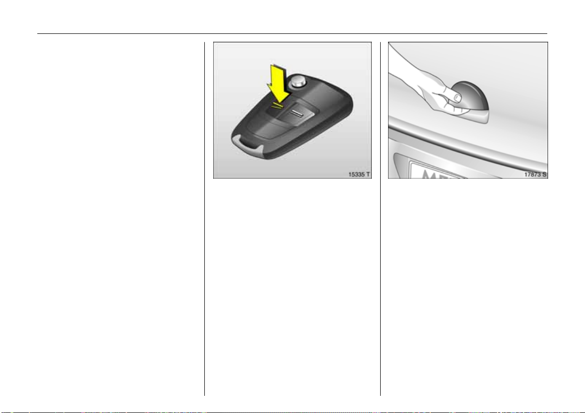
To unlock and open the doors:
Press button q and lift door
handle
All doors and the luggage compartment
are unlocked.
Country-specific version 3:
Pressing once unlocks the driver’s door,
and pres s ing twice unlocks the entir e
vehicle.
6 Door locks – see page 26,
keys – see page 26,
electronic immobiliser – see page 27,
ra dio frequency rem ote control –
see page 28,
central locking – se e page 30,
Vauxhall alarm system 3 – see page 34.
Picture no: 17873s.tif
To unlock and open the luggage
compartment:
Press button q on remote control
and operate button beneath
handle
6 Radio frequency remote control –
see page 28,
central locking – see page 30,
Vauxhall alarm system 3 – see page 34.
Page 8
3In Brief
Picture no: 13977s.tif
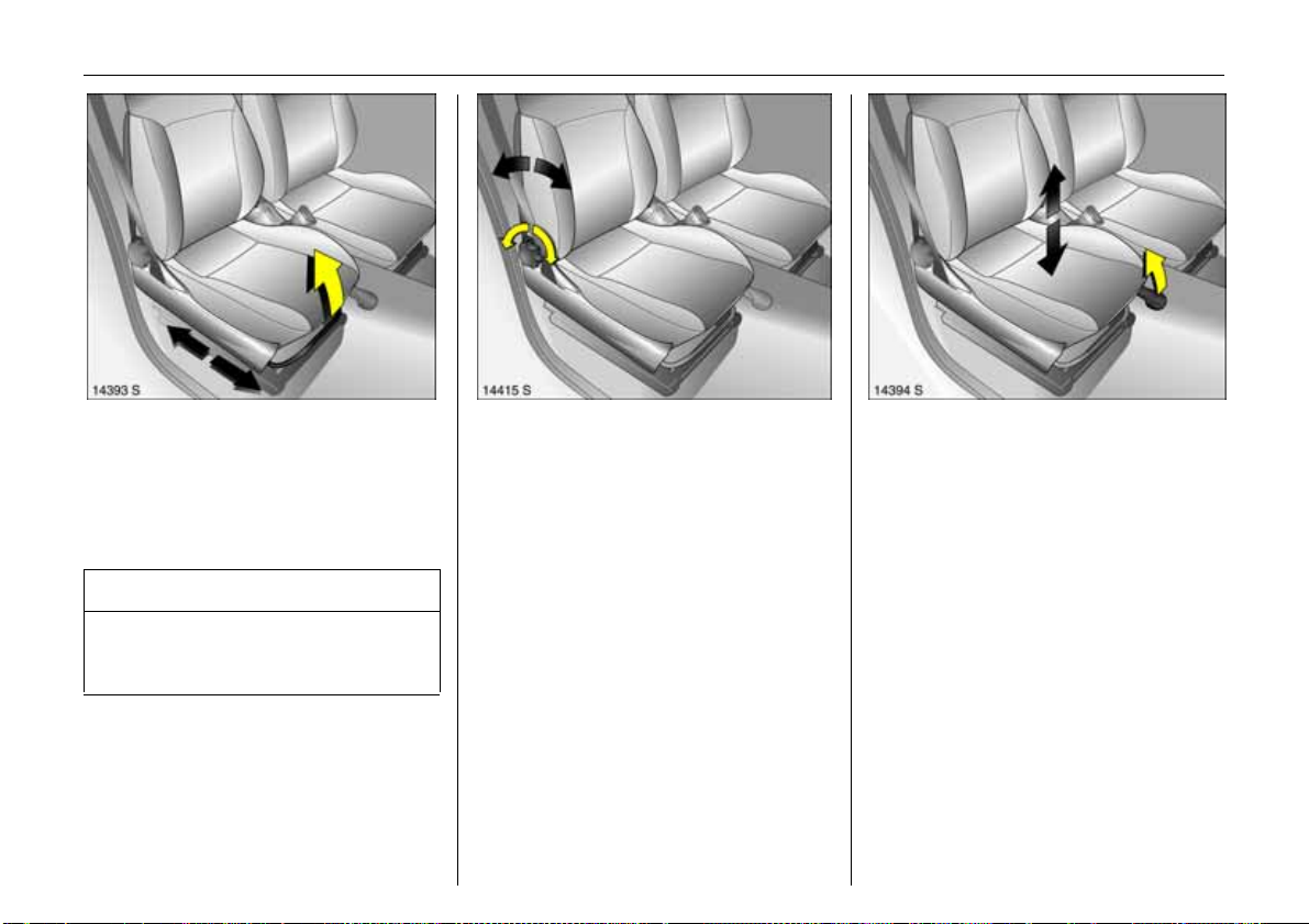
To adjust front seats:
Pull handle,
slide seat,
release handle
6 Seats – see page 43,
seat position – see page 44.
9 Wa rning
Important: Do not sit nearer than
10 in ches (25 cm ) from the stee ring
wheel, to permit safe airbag de ployment.
Picture no: 13978s.tif
Adjust front seat backrests:
Turn handwheel
Move backrest to suit seating position.
Do not lean on seat backrest while
adjusting it.
6 Seats – see page 43,
seat position – see page 44.
Picture no: 13979s.tif
To adjust fron t seat height:
Pull front lever at side
Lift lever and relieve some weight from seat
to rais e it or pres s down on seat cushion
with body weight to lower it.
6 Seats – see page 43,
seat position – see pag e 44.
Page 9
4In Brief
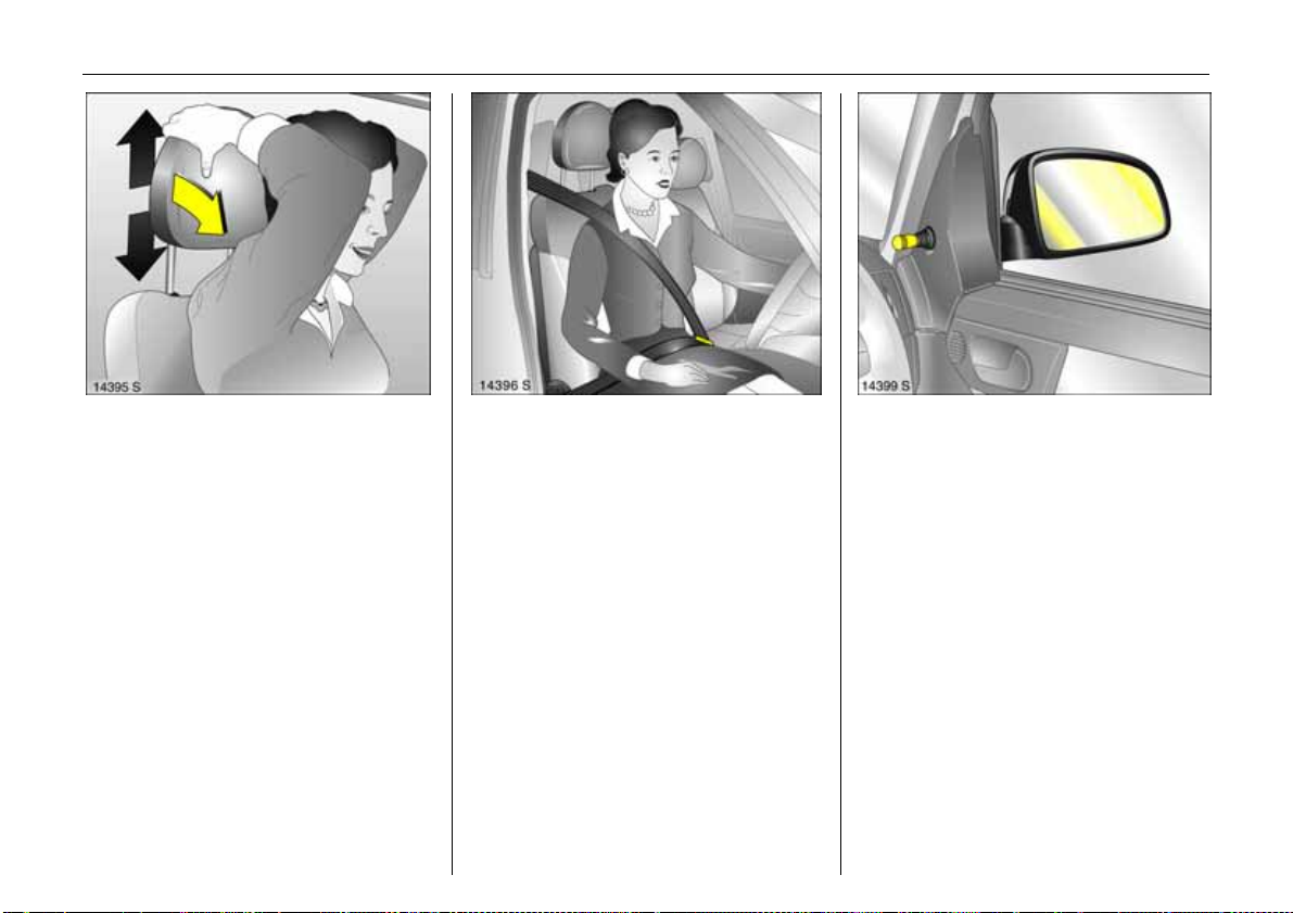
Picture no: 13980s.tif
To adjust head restraint height of
front a nd rear ou tboard seats:
Tilt he ad restra in t f orw ard to
release,
hol d and adjust h eight,
engage
6 H ead restraints – see page 45,
rear centre he ad restraint – see page 45,
head restraint position – see pag e 46,
head restraint removal – see page 46.
Picture no: 13982.tif
To fit seat belt:
Draw seat belt smooth ly from
inertia reel, guide over shoulder
and eng age in b uckle
The seat belt must not be twisted at any
point. The lap belt must lie snugly a gainst
the body . The front seat backrests mu st n ot
be tilted back too far (recommended
maximum tilting a ng le approx. 25°).
To release be lt, press red button on belt
buckle.
6 Three-point seat belts – see page 58,
airbag system – see page 67,
seat position – see page 44.
Picture no: 13985s.tif
To adjust exterior mirro rs:
From inside,
swivel lever in required direction
6 Mirrors – see p age 37,
further information, aspherical exterior
mirror 3 – see page 37.
Page 10
5In Brief
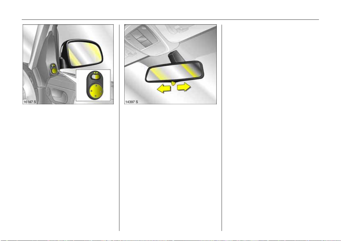
Picture no: 16099s.tif
To adjust electrically adjustab le
exterior mirrors 3:
Four-way switch in driver’s door
Toggle rocker switch to left or right:
Four-way switch moves appropriate mirror.
6 M irrors – see pag e 37,
fold-in exterior mirrors – see page 37,
further information, aspherical exterior
mirror, heated exterior mirrors 3 –
see page s 12, 37, 119.
Picture no: 14300s.tif
Adjusting in terior mirror:
Swivel mirror housing
Swivel lever on underside of mirror housing
to reduce dazzle at night.
6 Interior mirror – see page 38,
automatic anti-dazzle interior mirror 3 –
see page 38.
Page 11
6In Brief
Page 12

7In Brief
Page
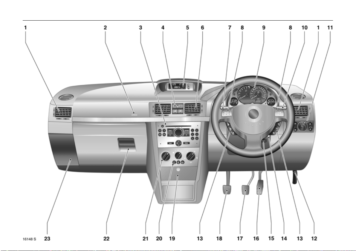
1 Side air v ents ................. .... ......... .... 118
2 Fron t pa ssenge r’s airbag . ......... ..... 6 7
3 Infotainment system 3 . .... ............ 114
4 Haza rd warning lights ...... .... .. 10, 107
LED for
Vauxhall alarm system 3 .......... .... ..34
Heated seats 3 ................. .... ..... ... 119
5 Central information display
for time, date,
outside temperature,
Infotainment system 3 . .... ............. . 92
6 Centre air v ents .... .... ......... ......... .... 118
7 Turn signal light, headlight flash,
dipped beam, hig h beam . ............. . 10
Door-to-door lighting func tion ..... 110
Cruise control 3 .... ............. .... ..... .... 151
8 Horn ........ ..... .... ..... ................. ..... .... .. 11
9 Instruments ...... ..... .... ..... .... ............. . 84
Pa ge
10 Windscreen wiper,
windscreen wash system,
headlight wash system 3 and
rear window wash system 3 ... 11, 103
11 Park ing lights, dipped beam ... ..... 105
Courtesy light ........... .... ......... ......... 111
Instrument illumination ........ ......... 1 11
Fog tail light ........ ..... .... ......... ......... 1 07
Front fog lights 3 ......... ......... ......... 1 06
Head lig ht range adjustment .... ..... 107
12 Bonnet release lever .... ............. .... 170
13 Remote control on steering
wheel ........... ..... .... ..... ............. .... .... 114
14 Starter switch
with steering co lu mn lock ......... ........ 9
15 Stee ring wheel adjustm ent 3 ... ..... ... 9
16 Ac celera tor pedal ............ ..... 138 , 139
17 Brake peda l .............. .... .... ..... 138, 154
Page
18 Clutch pedal 3 ... ..... ............. ..... .... 138
19 As htray .. ..... .... .... .............. .... ..... .... .. 80
Accessory socket and
cigare tte lighter ...... ......... ......... ...... 7 9
20 Air conditioning system 3 ... ..... .... 117
He ated rear w in dow ........ ........ 1 2, 119
Air recirculation system 3 ......... .... 123
21 C lim ate c ontrol .. ..... ......... ......... .... 117
22 Glove compartment ... ..... ......... ...... 8 1
23 Fusebox ...... .... .... ..... ............. ..... .... 188
Page 13

8In Brief
Control indicators
X
B
>
A
Z
v
S eat belt w arning device 3,
see page 84.
A dapti ve Forw ard
Lighting (AFL) 3,
see pages 84, 109.
Front fog lights 3,
see pages 85, 106.
Engine electronics,
transmission el ectronics,
immobi liser,
diesel fuel filter 3,
Easytronic3,
fault,
see pages 85, 27, 147.
Exhaust emissi on 3,
see pages 85, 147.
A irbag system s 3,
belt tensioners,
see pages 60, 72.
I
O
C
!
j
T
m
r
p
Engine oil pressure,
see page 86.
Turn signal l ights,
see page s 10, 86.
Headlight main beam,
see page s 9, 86.
Preheating system for
diesel engines 3,
diesel part icle filte r 3 ,
see page 88.
Easytronic 3,
start engine 3,
see page 133.
Easytronic 3,
winter program me ,
see page 135.
Cruise control 3,
see page 151.
Fog tail light,
see page s 87, 107.
Alternator,
see page 87.
R
u
S
EPS
v
Y
y
Brake system,
clutch system 3,
see page 87.
Anti-lock Brake System (ABS),
see page 156.
Engine oil level 3,
see page 88.
Electric Power Steering (EPS) 3,
see page 88.
Electronic Stability Program me
Pl us
(E SP ®
see page 149.
Fuel level,
see pages 88, 143.
Seat occup ancy r ecog nition 3,
see pages 73, 74.
) 3,
Page 14
9In Brief
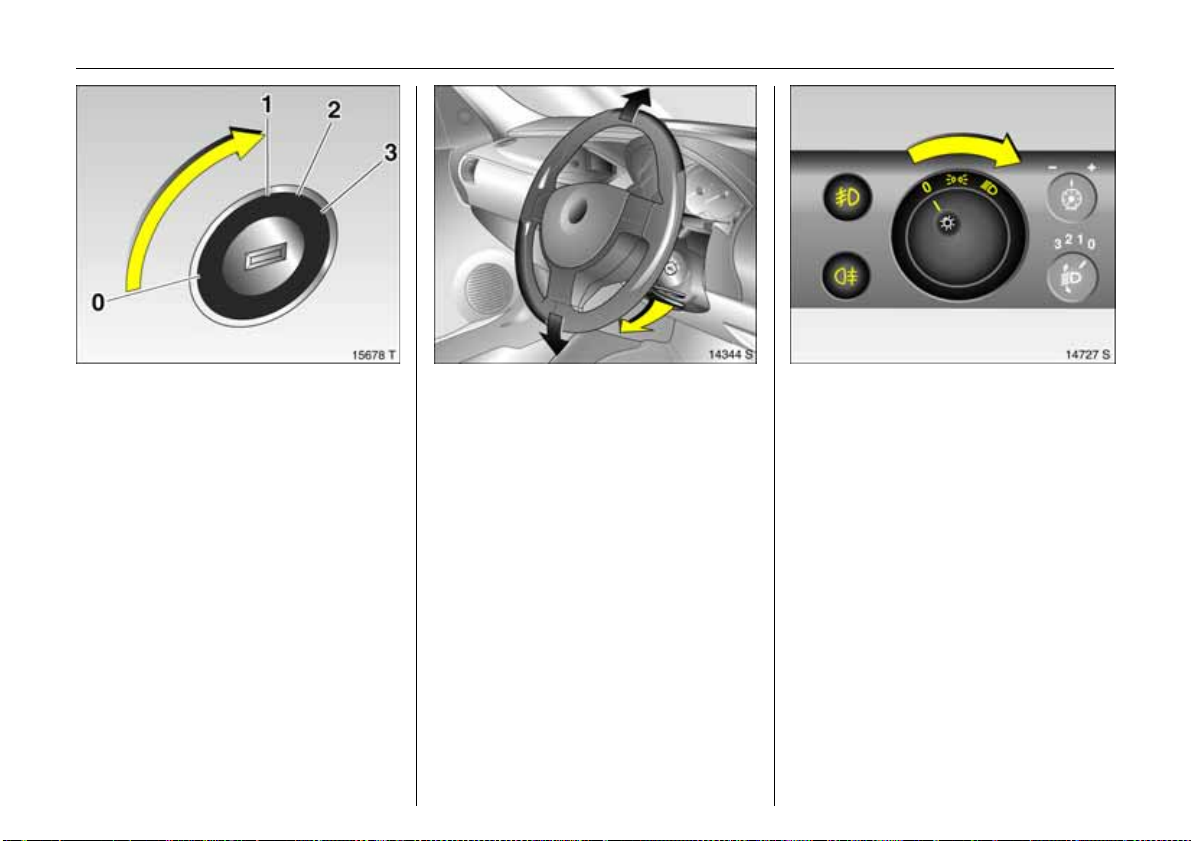
Picture no: 15678t.tif
Steering column lock and ignition:
Turn key to position 1;
Move st e e rin g wh ee l slig ht ly
to release lock
Posit ions:
0= Ignitionoff
1 = Stee rin g free , ignitio n off
2= Ignition on,
for diesel engines: preheating
3= Starting
6 Starting – see page 14,
electronic immobiliser – see page 27,
parking the vehicle – see page 15.
Picture no: 13981s.tif
Steering wheel adju stment 3:
Sw iv e l le v e r dow n,
adjust height,
swivel lever up,
engage
Adjus t stee ring wheel only when vehicle is
stationary and ste ering column lock is
re l ea s e d.
6 Airbag system – see page 67.
Picture no: 14727s.tif
Tur n li gh t sw it ch:
7
=Off
8
= Parking lights
9
= Dip ped be a m
or main beam
Press button:
>
= Front fog lights 3
r
= Fog tail light
0
= Courtesy light
6 Lighting – see p age 105,
headlight warning device – see page 103.
Page 15
10 In Brief
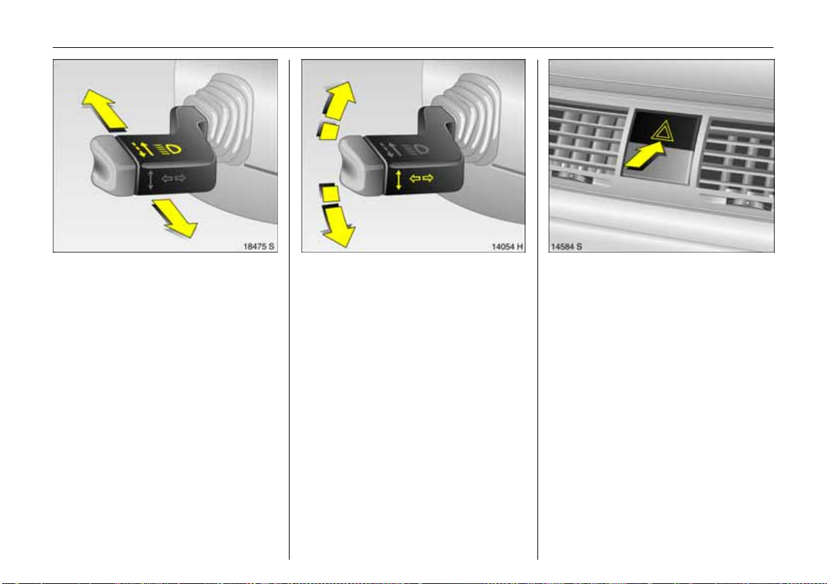
Picture no: 18475s.tif
Headlight flash, m ain b eam and
dip ped be a m:
Headlight
flash
=Pull stalk
towards
steering wheel
Main beam = Push stalk
fo rwa rd s
Dipped beam = Push stalk
forwards again
Main beam, headlight flash – see
page 106.
Picture no: 14054h.tif
Switch on turn signal lights:
Right = Stalk up
Left = S tal k down
6 Turn signal lights – see page 106.
Picture no: 14303s.tif
Hazard warning lights:
On = Press ¨
Off = Press ¨ ag ain
6 Hazard warning lig hts – see p age 107.
Page 16
11In Brief
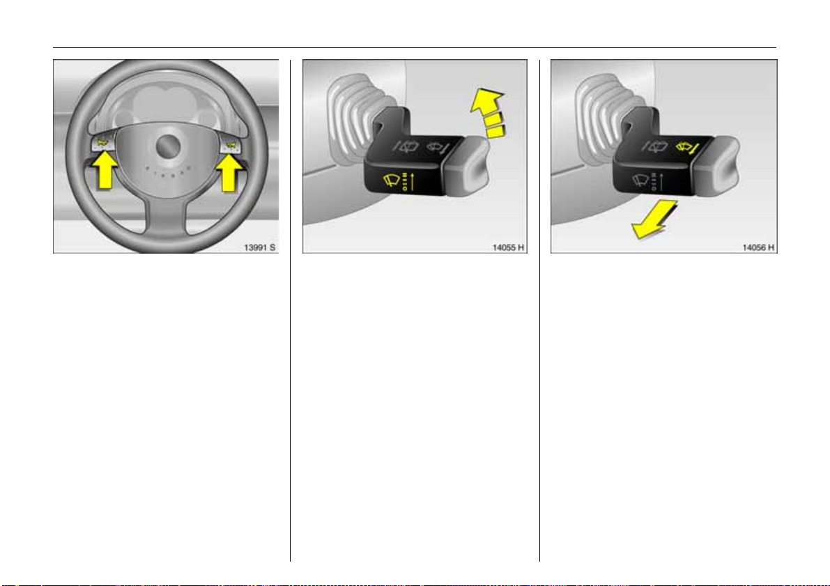
Picture no: 13991s.tif
Horn operation:
Press j
6 Airbag syste m 3 – see page 67,
remote control on steering wheel 3 –
see page 114.
Picture no: 14055h.tif
Windscreen wiper:
Stalk up
§
=Off
$
= Adjustable timed interval
wipe
%
=Slow
&
=Fast
6 Windscreen wiper – see page 103,
adjustable time d interval wipe 3 –
see page 103,
further information – see pages 204, 233.
Picture no: 14056h.tif
Operating windscreen and
headlight wash systems3:
Pull stalk towards steering wheel
The wiper will swipe for a few strokes.
The headlight wash system 3 can be
ope rated w hen the lights are on.
6 Windscreen wash system –
see page 104,
further information – see pages 204, 234.
Page 17
12 In Brief
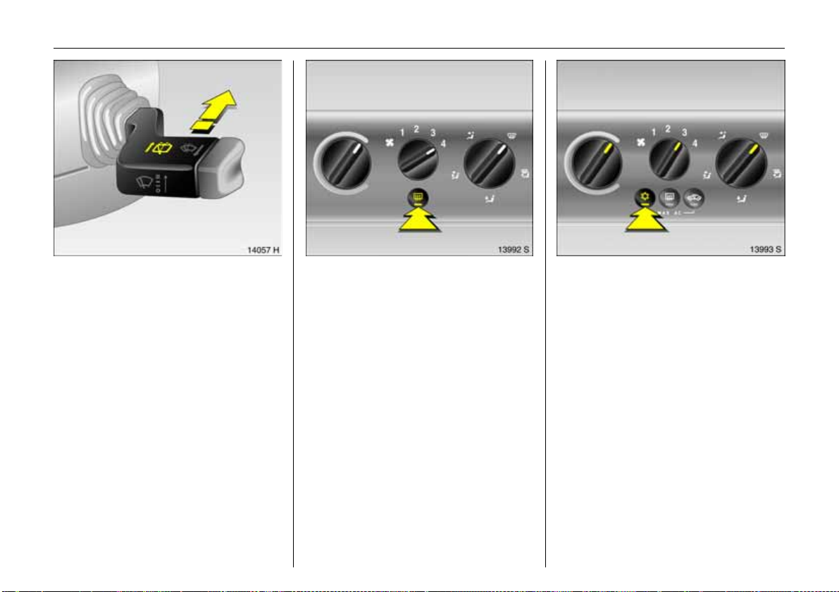
Picture no: 14057h.tif
Activate rear window wiper and
was h sy ste m:
Wiper on = Push stalk
forwa rds
Wiper off = Pull stalk
towards
steering wheel
Washer = Push stalk fully
forwa rd s an d
hold
6 R ear window w ash / wipe system –
see page 104,
further information – see pages 204, 235.
Picture no: 13992s.tif
Heated rear wind ow,
heated exterior mirrors 3:
On = Press Ü
Off = Press Ü again
6 Air conditioning – see page 117,
heated rear w indow – see page 119.
Picture no: 13993s.tif
To defrost misty or icy windows:
Turn rotary knob for temperature
and airflow clockwise,
air distribution to V;
Air conditioning system 3:
Press button n;
Electronic Climate Control
system 3:
Press button V
6 Climate control – see page 117,
air conditioning system 3 – see page 123,
Electronic Climate Control system 3 –
see page 126.
Page 18
13In Brief
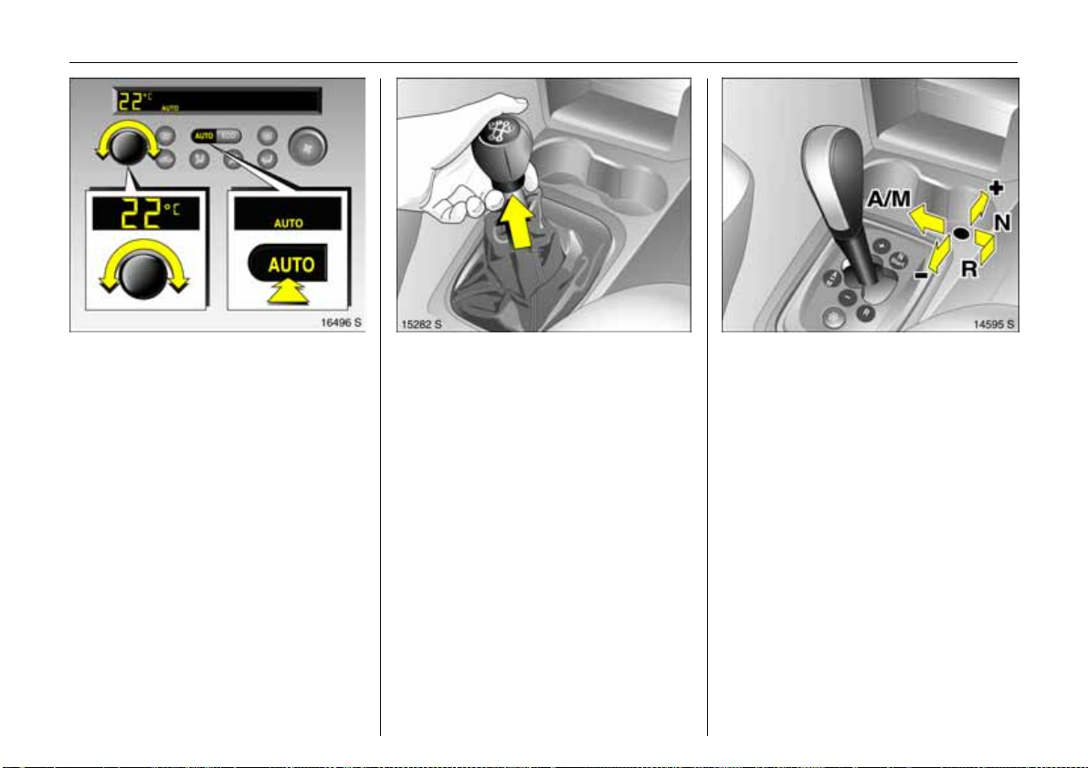
Picture no: 16496s.tif
To set automatic mode of
Electronic Climate Control
system 3 :
Press AUTO button,
set temperature using
left-hand rotary knob
6 E lectronic Clim ate C ontrol sys tem 3 –
see page 126.
Picture no: 15270s.tif
Manual transmission:
Reverse gear: with vehicle stationary,
three seconds after declutching pull the
ring up and e ngage gear.
If the gear d oes not e ngage , se t the lever in
neutral, release the clutch pedal and
depress again; then repeat gear selection.
Picture no: 14175s.tif
Easytronic 3:
N = Idle / start position
o
=Drive position
(c entre position)
+ = Higher gear
-=Lower gear
A/M = Switch between
Automatic mode and
Manual mode
R=Reverse gear
(with selector lever lock)
To move the selector lever from N to R,
press the button on the lever.
Only startin N with footbrake applied.
6 Eas ytron ic 3 – se e page 132.
Page 19
14 In Brief
Before starting-off, check:
z Tyre pressure and tyre condition,
see pages 160, 216.
z Engine oil level and fluid levels in engine
compartment, see pages 228 to 235.
z All windows, mirrors, exterior lighting
and num ber p la tes are fre e from dirt,
snow and ice and are operational.
z No obje cts are placed in front of the re ar
window, on th e ins trume nt panel or in
the area in which the airbags inflate.
z Seats, seat belts and mirrors are
correctly adjusted.
z Brake op eratio n.
To switch on the ignition, only turn the key
to position 2.
6 Electronic imm obiliser – see page 27,
diesel fuel system – see page 170,
further information – see pages 138, 171.
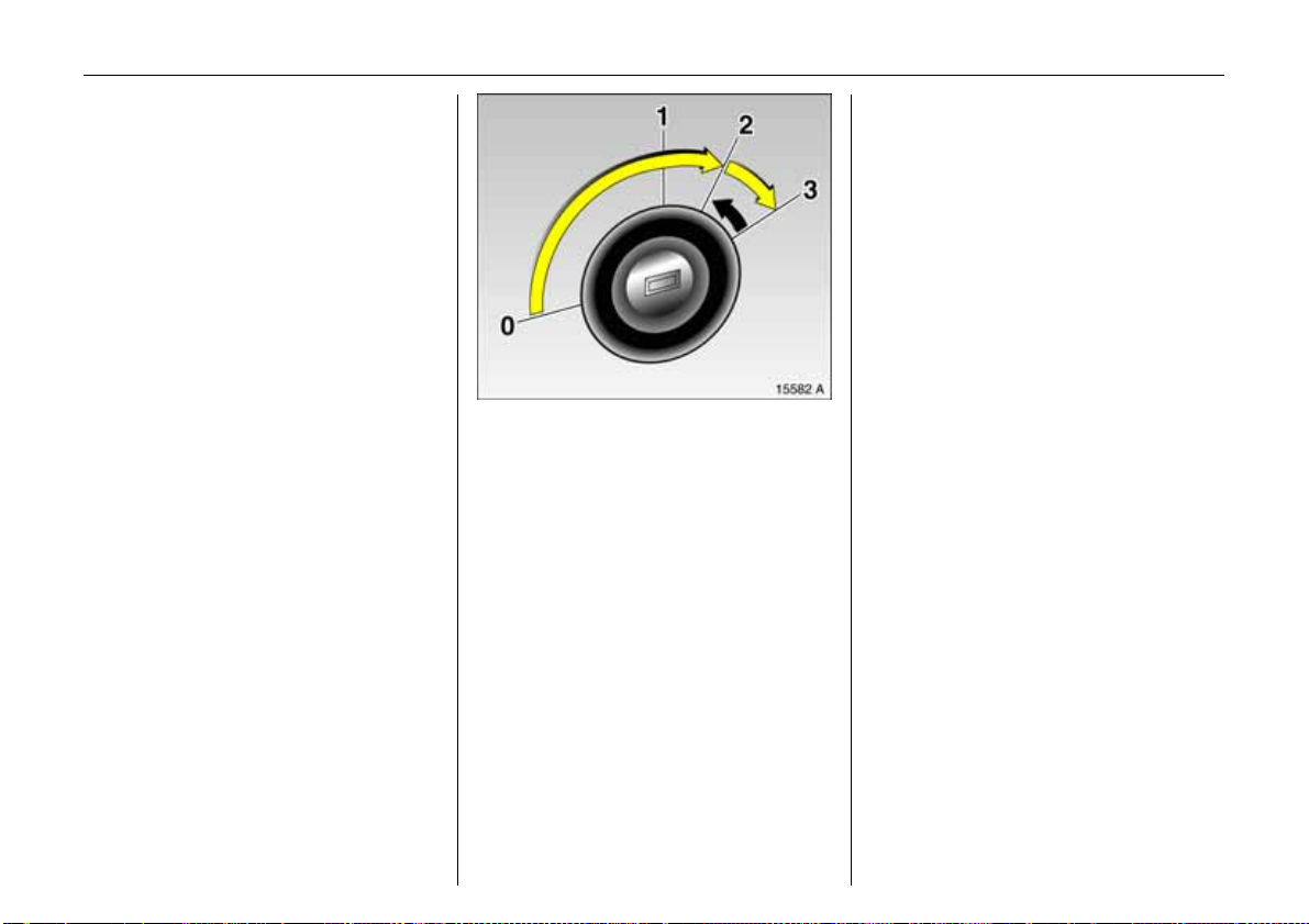
Picture no: 15582a.tif
To start engine:
Operate clutch and brake,
Easytronic 3 in N,
do not accelerate,
Petrol engines: key to 3;
Diesel engines: key to 2,
when control indic ator ! goes
out1), turn key to 3;
release key once engine is
run ning
Before restarting or when switching off the
engine, turn key back to position 0.
1)
Preheating system switches on only if outside
temperature is low.
Page 20
15In Brief
6 Further information – see pages 27, 138,
radio frequency remote control –
see page 28,
central locking system – see page 30,
Vauxhall alarm system 3 – see page 34,
vehicle decommissioning – see page 237.
Picture no: 14714s.tif
Releasing th e handbrake:
Raise lever slightly,
press lock button,
lower lev er fully
6 Handbrake – see pag e155.
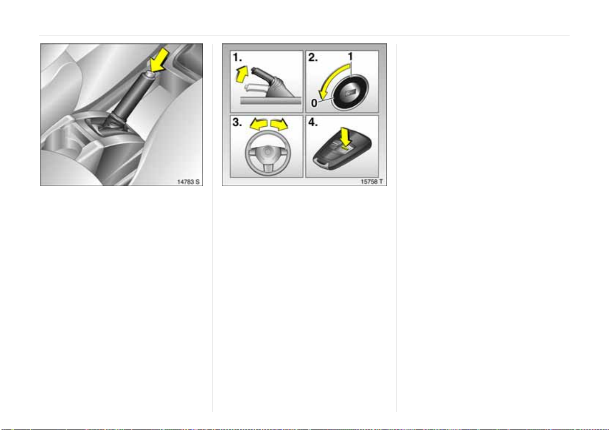
Picture no: 15758t.tif
Parking the vehicle:
Apply handbrake firmly,
switch engine off,
remov e k e y,
lock steering wheel,
loc k ve h i cle
To lock vehicle and arm the Vauxhall alarm
sy ste m 3, press button p.
To activate the mechanical anti-theft
lock ing syste m, p res s b utton p twice.
Page 21

16 In Brief
Advice when parking:
z Do not park the vehicle on flammable
surfaces as combustion could occur due
to th e h ig h ex ha us t te mp erat u re s.
z Always apply the handbrake firmly.
Apply the handbrake as firmly as
possible on uphill or downhill slopes. To
reduce operating forces, a pply
footbrake at the same time.
z Close windows, sliding roof 3 and tilting
roof 3.
z With manual transmission, select first
gear or reverse gear. With Easytronic 3,
move selector le ver to c entre position
before switching ignition off.
z On vehicles with Easytronic 3, control
indicator R flashes for a few second s
after the ignition is switched off if the
handbrake has not been applied.
z Turn steering wheel until lock is felt to
engage (anti-theft protection) after first
withdrawing the ignition key.
z The engine cooling fans may run after
th e engine has be en switched off,
see page 227.
6 Further information –
see pages 235, 237.
Page 22

That was the most important
information for your first drive
in your Meriva in brief.
The othe r pages of this chapter
contain a d escription of some
interesting functions in your
vehicle.
The re ma in ing ch apte rs of the
Owner’s Manual contain
important information on
operation, safety and
maintenance as well as a
com plete index.
17In Brief
Page 23
18 In Brief
Flex ible Seat System (FlexSpace)
The rear row of seats in your vehicle offers
three seats or, with the centre seat lowered,
two seats with more seating space . The
outboard seats can be lowered to obtain a
level loading surface.
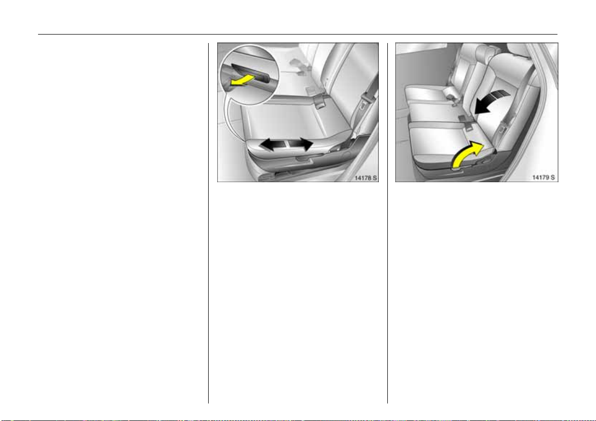
Move rear outboard sea ts
Picture no: 14178s.tif
z Pull handle under seat,
z Slide seat,
z Re lease handle and a llow seat to
engage in p osition.
The backrests must not be in the rearmost
position when the seats are moved ba ck, in
order to prevent damage.
Adjust or fold backrest of outboard seats
Picture no: 14179s.tif
z Pull handle on outboard side of seat,
z Guid e backrest in to the relevant position,
z Release h andle and allow s eat to audibly
engage in position.
Page 24
The b ackrest can engage in several
positions. In addition, the backrest can be
folded all the way down to the seat cushion
when extending the luggage
compartment.
9 Wa rning
To prevent injur ies, a lways hold s eat
backrest firmly and guide downwards
when folding.
19In Brief
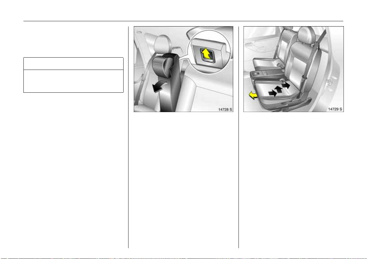
Low er c entr e seat
Picture no: 14728s.tif
z Ho use centre seat belt in the belt re ta iner
in the roof,
z Insert seat belts into recesses in seat
cushion,
z Slide centre rear seat head restraint all
the way down,
z Pull release handle at rear of centre seat
backrest. Tilt back rest forwa rds and
engage.
Two r ear seat s w ith more se ating space
Picture no: 14729s.tif
z Lower centre seat,
z Adjust backrest to centre position,
z Pull handle beneath seat.
z Slide seat all the way back, then towards
the centre of the vehicle and then further
rearwards to the desired position,
z Release handle and allow seat to
engage in position.
Page 25
20 In Brief
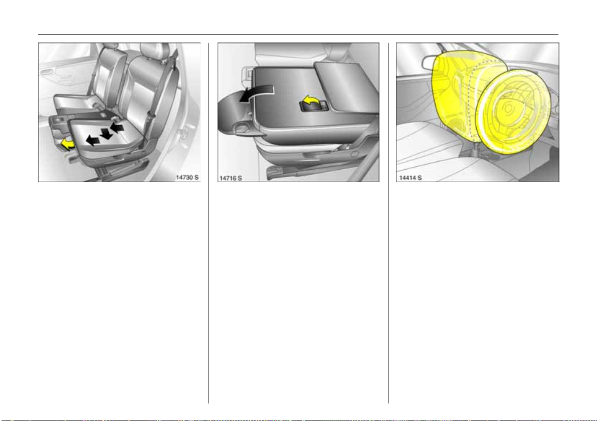
Three seats
Picture no: 14730s.tif
z Adjust backrest to centre position,
z Pull handle beneath seat.
z Slide seat all the way forwards, then out
towards the door and then further
forwards to the desired position.
z Release handle and allow seat to
engage in position,
z Raise centre seat.
Fold ing down out board seats
Picture no: 14716s.tif
z Pull seat belt from belt guide on
backrest,
z F o l d d o w n o u tb o a r d r e a r s e a t b a c k r e s t s ,
z To achieve a level loading surface, pull
release handle on back of backrest and
push seat down until it latches into
position.
Picture no: 14125s.tif
Airbag system
The airbag system consists of several
separate systems.
Front airb ag system
The front airbag system will be triggered in
the event of a serious accident involving a
frontal impact and forms safety cushions
fo r th e d riv er an d front passenger. The
forward movement of the driver and front
passenger is checked and the risk of
injuries to the upper body and head are
thereby substantially reduced.
Page 26
21In Brief
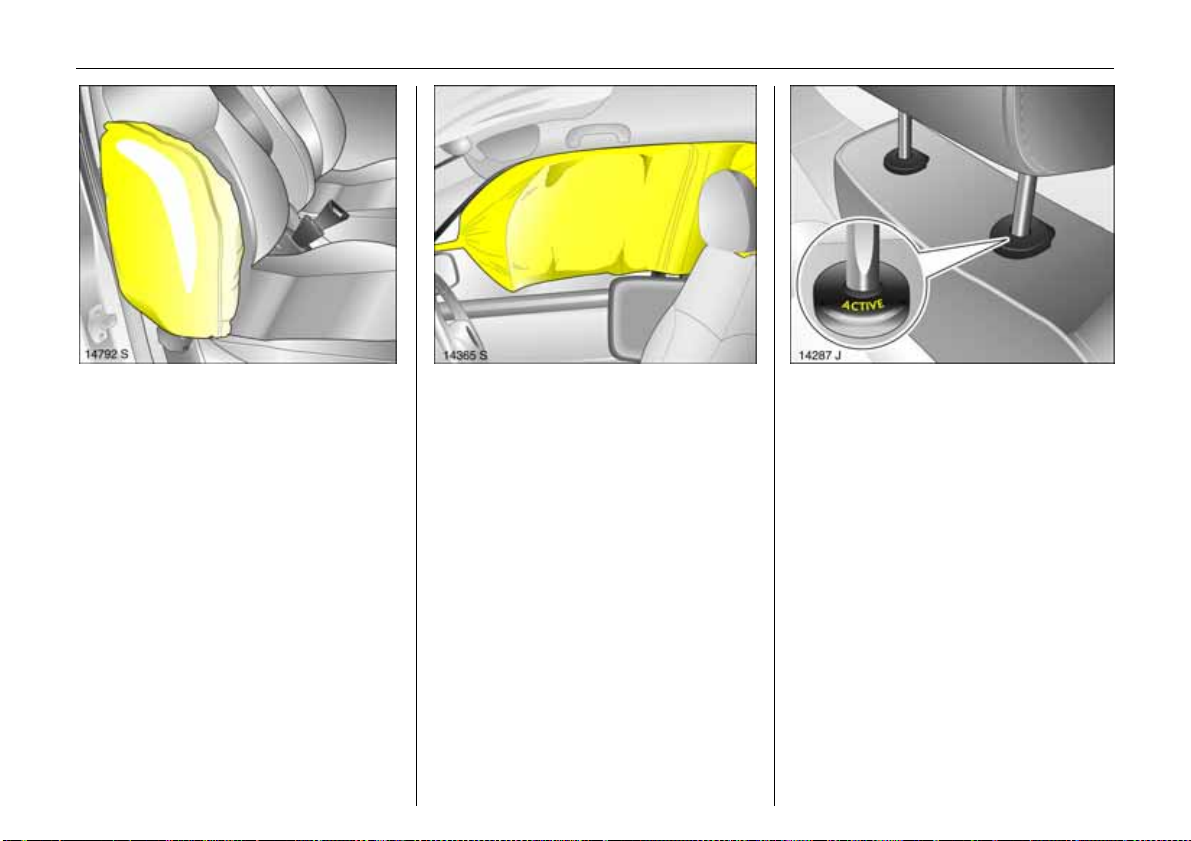
Sid e airbag sy stem 3
Picture no: 14742s.tif
Th e side airbag is trigg ered in the ev en t of
a side-on collision to form a safety cushion
for the driver or front passenger in the
respective door area. This substantially
reduces the risk of injury to the upper body
and pelvis.
Curtain airbag system 3
Picture no: 14127s.tif
The curtain airbag system triggers in case
of a side-on collision and provides a safety
barrier in the head a rea on the respective
side of th e v ehicle. This re du ces the risk of
injury to the head considerably in case of a
side-on collision.
6 Airbag systems – see page 67.
Picture no: 14287j.tif
Active head restraints 3 on front
seats
In the event of a rear-end impact, the
active head restraints automatically tilt
forward a little. The head is more
effectively supported b y the head re straint
and the danger of injuries caused by
whiplash in the neck area is reduced.
Active head restraints are identified by the
lettering ACTIVE on the head restraint
guide sleeves.
Page 27
22 In Brief
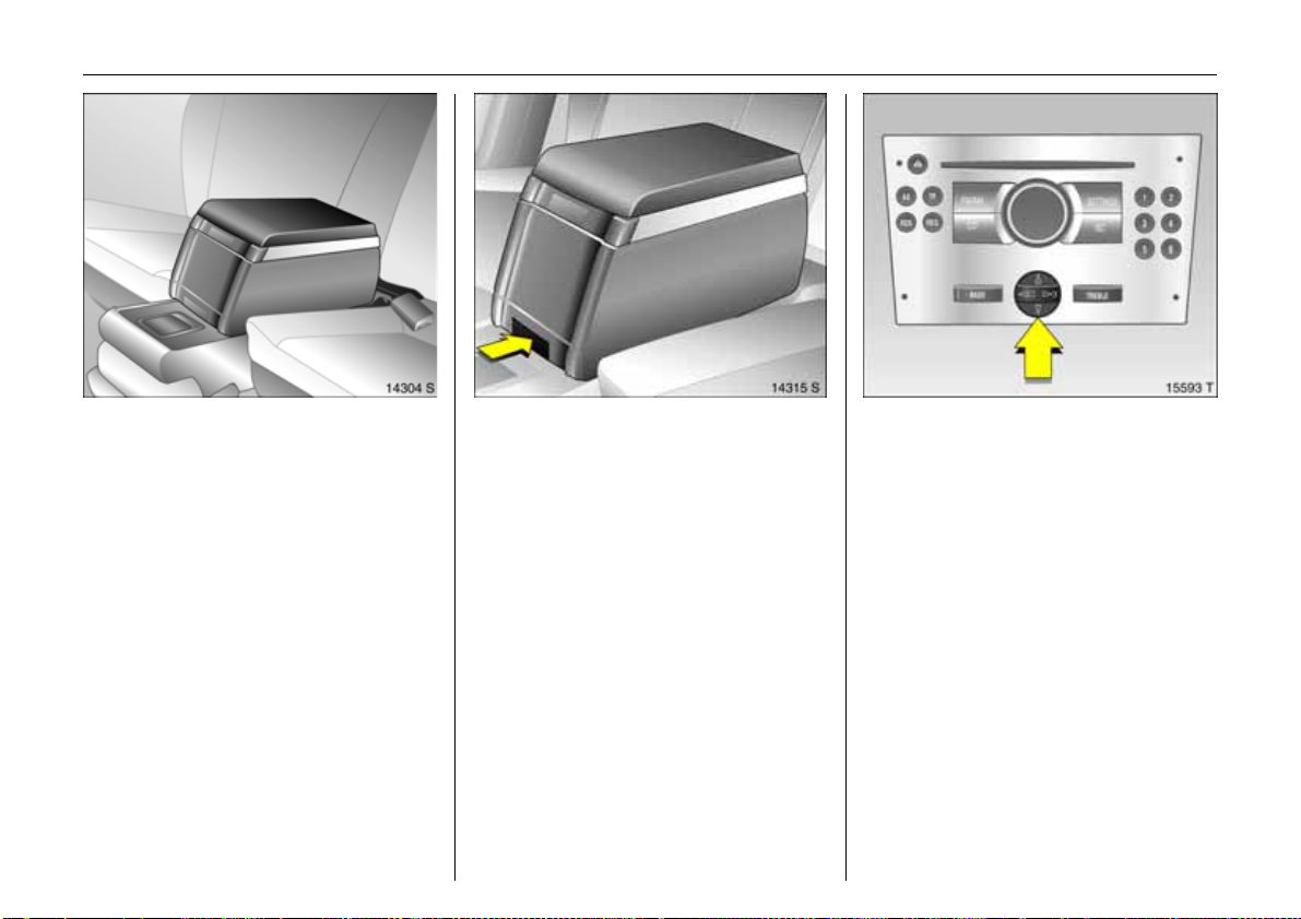
Picture no: 14304s.tif
Travel Assistant 3
The Trav el Assistant contains:
z Ar m res t,
z Tr ay ,
z Drink holders.
The Travel Assistant is mounted on the
lowered ce ntre seat (see pag e 19).
Dismantling the Travel Assistant
Picture no: 14315s.tif
z Press lower button on the Travel
Assistant,
z Pull Travel Assistant upwards out of
recesses,
z There is a carrying handle on the b ack to
facilitate transport.
Picture no: 15593t.tif
Operating menus in the
information display 3
Menu op tions are selected using menus
and using the buttons / four-way button or
the multi-function knob of the Infotainment
system 3 or the buttons 3 on the steering
wheel. The respective menu options are
s h ow n on t h e dis pl a y.
Selection using four-way button:
press four-way button at top, bottom , left
or right.
Page 28
Ü Board Computer 19,5° 19:36
BC 1 All values
BC 2
Timer
1111
257.0 miles
Ø40mph
7.0 gal s
8888
Ø 31.0 mp g
23In Brief
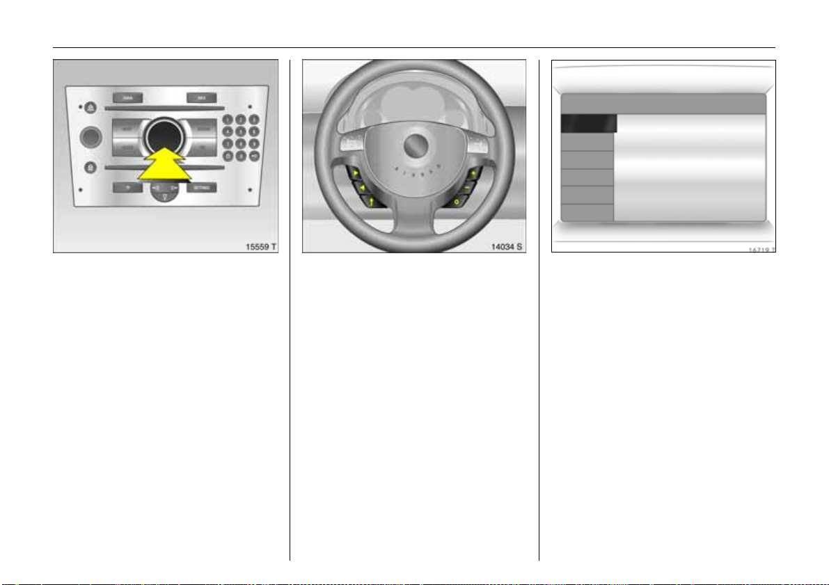
Selection using multi-function knob 3:
Picture no: 15559t.tif
Rotate and press multi-function knob.
To exit a menu, turn the multi-function
knob left or right to Return or Main and
select.
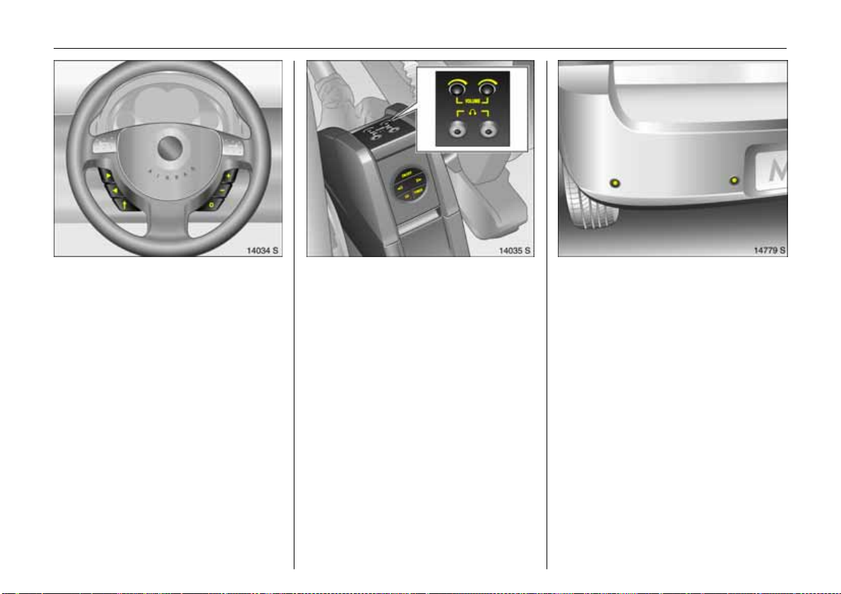
To select with steering wheel buttons:
Picture no: 14034s.tif
Select menu options via the menus and the
buttons.
6 Information display – see p age 92.
Picture no: 16719t.tif
Trip computer 3
The trip comp uters provide information on
driving da ta, which is continually recorded
and evaluated electronically.
Functions:
z Range,
z Instantaneous consumption,
z Distance travelle d,
z Average spee d,
z Effective consumption,
z Average consumption,
z Sto p watch.
6 Trip computer – see page 99.
Page 29
24 In Brief
Picture no: 14034s.tif
Remote control on steering
wheel 3
The functions of the Infotainment system
and the information display can be
operated with the buttons on the steering
wheel.
Further information is available in the
Infotainment system operating
instructions.
Picture no: 14035s.tif
Twin Audio 3
Twin Audio p rov ides rear seat occupants
with the opportunity to listen to a different
audio source than the one selected by the
driver on the Infotainment system.
Only an audio source tha t is not currently
active on the radio system can be
controlled using Twin Audio.
Two headphone connections are available,
with se parate volume controls.
Further information is available in the
In fotainment sy ste m op e ra tin g
instructions.
Picture no: 14779s.tif
Parking distance sensors 3
When rev erse ge ar is selecte d, th e p arkin g
dis tance se nsors switch on au t o mat ica lly .
If the vehicle approaches an obstacle when
reversing, a series of signals can be heard
in the vehicle interior. The interval between
the signals becomes shorter as the
distance is reduced. If the distance is less
than 30 cm, the signal will be continuous.
6 Parking distance sensors 3 –
see page 153.
Page 30
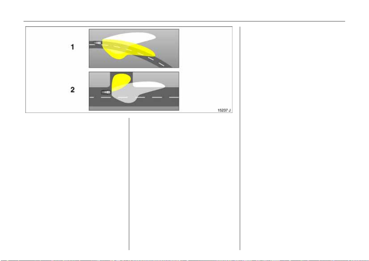
Picture no: 15209j.tif
Adaptive Forward Lighting
(AFL) 3
AFL im proves illumination of:
z Curves (curve lighting),
z Intersections and tig ht turns
(turn lighting).
Curve lig hting ( 1)
Picture no:
The light beam pivots based on steering
wheel position and speed (from approx. 6
mph (10 km/h)).
The headlights shine at an angle of up to
15° to the right or left of the direction of
travel.
25In Brief
Turn lig hting ( 2)
An add itional light illuminates at certain
steering wheel settings (after rotation of
approx. 90°), turn signal settings and
speeds (up to approx. 25 m ph (40 km/h)).
The light beam projects at a 90° angle to
the left or right of the vehicle up to a
distance of a pprox. 30 metres.
Reverse function
Turning the lights on, selecting re verse
gear selected a nd switching on a turn
signal light causes the turn lighting to be
switched on for the respective side.
When th e turn s ignal is sw itc hed off, the
turn lighting continues to illuminate for
app rox . 15 se cond s.
6 Adaptive Forward Lighting (AFL) 3 –
see page 109.
Page 31

26 Keys, Doors, Windows
Keys, Doors, Windows
Re placem ent ke ys ... ..... .... ......... ......... . 26
Lock cylinders .......... ..... .... ......... ......... . 26
Ca r Pass... .... .... ..... .... .............. .... .... ..... . 26
Key with retractable key blade 3 ..... . 26
Electronic immobiliser....... ......... ......... . 27
Radio frequency remote control .. ..... . 28
Central locking sys tem . ......... ........ ...... 30
Fault when locking or unlockin g... ...... 32
Luggage compartment.... ..... .... ......... . 32
Vauxhall alarm system 3.......... .... ..... . 34
Child s afety locks ................... .... ......... . 36
Exterior mirrors ..... ......... ......... ........ ...... 37
Interior mirror .. ......... ......... ......... ......... . 38
Door windows ...... ......... ......... ........ ...... 39
Ele ctric win dows 3 ........ ......... ........ ...... 39
Sunroof and tilting roof 3 ......... ......... . 41
Replacement keys
The key number is specified in the vehicle
documents and in the Car Pass 3.
The key is a constituent of the electronic
immobiliser. Ordering keys fr om a Vau xhall
Authorised Repairer guarantees problem free operation of the electronic
immobiliser.
Keep the spare key in a safe place.
Locks, see page 204.
Lock cylinders
Des igned to free-wheel if they are
forcefully rotated without the correct k ey or
if the correct key is not fully inserted.
To reset, turn cylinder with the correct key
until its slot is vertical, remove key and then
re-insert it. If the cylinder still free-wheels,
turn the key through 180° and repeat
op er at io n .
Car Pass
The Car Pass contains a ll of the vehicle’s
data and s hould therefore n ot be kept in
the vehicle.
Have your Car Pass to hand when
co nsult ing a V aux hall Au thorised Re pa irer.
Picture no: 15760t.tif
Key with retractable key blade 3
Press button to extend. Press button to
retract and audibly engage key blade.
Page 32

27Keys, Doors, Windows
If control indicator A illum inates after the
engine is started, there is a fault in the
engine electronics or transmission
electronics 3, (see pages 85, 137, 147), or
there is water in the diesel fuel filter 3,
(see page 230).
Not e
The immobiliser does not lock the doors.
Therefore, always lock the vehicle before
leaving it unattended and enable Vauxhall
alarm system 3. See page 34.
Picture no: 15761t.tif
Electronic immobiliser
Using a transponder housed in the key, the
system checks whether the vehicle may be
s ta r ted u s ing th e ke y th at has b e en
in serted. If th e k ey is recogn ised as
"authorised" the engine can be started.
The electronic immobiliser activates
automatically when the k ey is removed
from the starter switch.
Th e code numbe r of the electronic
immobiliser is given in the Car Pass.
Control i nd icator fo r imm obilise r A
Picture no: 17880s.tif
Control indica tor A illuminates briefly
wh en th e ig nitio n is sw itch e d on .
If the control indicator flashes when the
ignition is on, there is a fault in the system;
the engine cannot be started. Switch off
the ignition and then repeat the start
attempt.
If the control indicator A continues to
flash, try to start the engine using the spare
key and contact a workshop for assistance.
Page 33

28 Keys, Doors, Windows
Radio frequency remote control
Depending on equipment level, the vehicle
comes equipped with one of the remote
controls illustrated on this page.
The radio frequency remote control is
integrated in the key.
Us ed to op erate:
z Central locking system,
z Mechanical anti-theft locking system,
z Vauxhall alarm system 3.
In vehicles with electric windows in all
doors 3, the remote control can be used to
closed the windows.
The remote control has a range of approx.
Picture no: 15330t.tif
5 metres. This range can be affected by
outside influences. Aim the remote control
at th e v ehicle to op erate.
Handle the remote control with care,
protect it from moisture and high
temperatures and avoid unnecessary
op er at io n .
The hazard warning lights flash to indicate
that the rem ote control is operational.
C entra l locking s yste m,
Picture no: 15331t.tif
see page 30.
Mechanic al anti -theft locking system,
see page 28.
Vauxhall alarm system 3,
see page 34.
Electric windows 3 ,
see page 39.
Page 34

29Keys, Doors, Windows
Fault
If the central locking system cannot be
operated with the remote control, it m ay b e
due to the following:
z The range of the remote control has
been exceeded.
z Remote control battery voltage is too
low. Battery replacement - see next
column.
z If the remote control is frequently and
repeatedly operated outside the
recep tion range of the vehicle (e.g. too
far from vehicle), the remote control will
no longer be recognised. Remote control
synchronisation, see end column.
z If the centra l locking system is
overloaded as a result of repeated
operation at short intervals. The power
supply is cut off for a brief period.
z Interference from h igher-power radio
waves from other sources.
To eliminate the cause of a fault, we
recommend contacting a workshop for
assistance.
Open driver’s door with ke y, see pa ge 32 .
Key with fix ed blade,
see Fig. 15331 T on previous page.
Have the workshop change the battery.
In the event of a functionality problem or
ba ttery r epl acement, synchroni se the
remote control.
After changing the battery, unlock the
door using the key in the driver’s lock
cylinder, see page 32. The remote control is
synchronised by inserting the key in the
starter switch.
Picture no: 15332t.tif
Remote con trol b attery replacement
Replace the battery as soon as the range
of the remote control becomes reduced.
Ke y with re trac ta ble k ey bl ad e ,
see Fig. 15330 T on previous page.
Extend key, see page 26. Open remote
control. Replace battery - battery type, see
page 218 - noting installation position.
Close remote control.
Make sure that you dispose of old batteries
in accordance with environmental
protection regulations.
Page 35

30 Keys, Doors, Windows
Picture no: 15335t.tif
Central locking system
For doors, luggage compartment and tank
flap.
To unlock
Press button q on the remote control
– or, from the ins ide –
pull up lock button on driver’s door.
When the mechanical anti-theft locking
system is enabled, the doors cannot be
unlocked by pulling up the lock buttons.
Country-specific version 3 :
Pressing once unlocks the driver’s door,
and pressing twice unlocks the entire
vehicle.
To lo c k
Picture no: 15333t.tif
Close doors, luggage compartment and
tank flap.
Press button p on the remote control
– or, from the inside –
press lock button on driver’s doo r when th e
doors are closed.
Mechanic al anti -theft locking system
Picture no: 15334t.tif
9 Warnin g
Do not use the system if there are people
in the vehicle! The doors cannot b e
unlocked from inside.
All the doors must be closed.
Press the p button on the remote control
within 10 seconds of locking.
Lock buttons on all doors are positioned
such tha t doors cannot be opened.
If the ignition was on, the driver’s door
must be opened and closed once so that
the vehicle can be secured.
Page 36

31Keys, Doors, Windows
Note
z To prevent the driver from being
inadvertently locked out, the button on
the driver’s door cannot be depressed
when the door is open.
z If the driver’s door is not closed properly,
the central lock ing sy stem will unlock
again immediately after locking.
z Approx. 30 seconds after unlocking
using the remote control, the doors lock
again automatically if no door is
opened.
z To lock the doors from inside (e.g. to
prevent unwanted entry from outside),
press lock button on d riv er’s door when
the doors are closed.
z Locked doors unlock automatically if an
accident of a certain severity occurs (to
permit outside assistance). Prerequisite:
Ignition must not be switched off.
Closing windows 3 from outside
Picture no: 17899s.tif
9 Warning
Exercise care when operatin g e lectric
windows. Risk of injury, especially for
children.
Vehicle passeng ers must be info rmed
accordingly.
Keep a close watch on the windows when
closing them. Ensure that nothing
becomes trapped in the m as they move.
On vehicles with electric windows in all
doors 3, the windows can be closed from
outside:
Hold button p on the remote control
depressed until all of the windows have
closed completely.
Further information on electric windows,
see page 39.
Fault
If the central locking cannot be operated,
this can be for one of the following reasons:
z If the central locking system is
overloaded as a result of repeated
operation at short intervals. The power
supply is cut off for a brief period.
z Defective fuse in fusebox, see page 188.
To eliminate the cause of a fault, we
recommend contacting a workshop for
assistance.
Operate driver’s door with key, see next
page.
Page 37

32 Keys, Doors, Windows
Picture no: 17881s.tif
Fau l t wh e n lo cki n g or u n loc ki ng
Fault in remote control
To unlock
Turn key clockwise in driver’s door lock,
return to the vertical position and remove.
Th e entire vehicle is unloc ked. Switc h on the
ignition to deactivate the Vauxhall alarm
system 3.
To lock
With the driver’s door closed, turn the key
anticlockwise in the lock, return to the
vertical position and remove. The entire
vehicle is locked.
Malfu ncti on i n central lock ing sy stem
To un l o c k
Turn key clockwise in driver’s door lock,
return to the vertical position and remove.
The driver’s door is unlocked. The other
doors can be unlocked by pulling up the
interior lock buttons (not possible if the
mechanical a nti-theft locking system is
enabled). Switch on the ignition to
deactivate the Vauxhall alarm system 3.
To lock
With the driver’s door open, press the
interior lock button of the other doors.
Close the driver’s door. Turn the key
anticlockwise in the lock, return to the
vertical position and remove. The tank flap
cannot be lo cked if the re is a ma lfun ction in
the central locking system.
Note
z The mechanical a nti-theft locking
system and the Vauxhall alarm system 3
cannot be activated with the key.
z To deactivate the Vauxhall alarm
system 3 af ter o pening a d oor, swit ch on
the ig nition.
z To eliminate the cause of a fault, we
recommend contacting a workshop for
assistance.
Picture no: 15335t.tif
Luggag e com partment
To unlock
Press button q on the remote control. The
luggage compa rtment is unlocked
together with the doors and the tank flap.
Country-specific version 3:
Press button q twice on the remote
control; one press unlocks the driver’s door,
two presses unlocks the entire vehicle.
Page 38

33Keys, Doors, Windows
To open
Picture no: 17873s.tif
The lugga ge compartment is opened by
operating the unlocking button beneath
the handle.
9 Wa rning
Do not drive with the luggage
compartment open or ajar, e.g. when
transporting bulky objects, since toxic
exhaust gas could penetrate the interior.
Fitting of accessories on the tailgate will
increase its weight. If it becomes too heavy,
it will then not stay open.
To clo s e
Picture no: 17882s.tif
There are two handles on the inside of the
tailgate for closing the luggage
compartment.
Do not operate the unlocking button
beneath the handle when closing.
Otherwise the luggage compa rtment will
once again b e unlocked.
To lock
Picture no: 15333t.tif
Press button p on remote control.
Page 39

34 Keys, Doors, Windows
Vauxhall alarm system 3
Monitors:
z The doors, luggage compartment,
bonnet,
z The passenger compartment,
z Vehicle tilt, e.g. if it is raised,
z Th e ig ni t i on .
To activate
Picture no: 15334t.tif
All doors, windows, sunroof 3, tilting roof 3
and the bonnet must be closed.
Press button p on the remote control to
activate the Vauxhall alarm system and
lock the doors.
If the ignition was switched on, the driver’s
door must be opened and closed once so
that the anti-theft alarm system can be
swi tch ed on.
Act ivat ion without monitoring of
Picture no: 11575s.tif
passenger comp artment or vehicle tilt
E.g., if animals are to be left in the vehicle.
1. Close luggage comp artm ent and
bonnet.
2. Press button in front of the courtesy light
(with ignition off); LED in the hazard
warning light button flashes for a
maximum of 10 seconds.
3. Close doors.
4. Switch on anti-theft alarm system . LED
illuminates. After approx. 10 seconds,
the anti-theft alarm system is activated
without monitoring of the passenger
compartment or vehicle tilt. The LED
flashes until the system is switched off.
Page 40

After the first 10 seconds of anti-theft
alarm system activation:
z LED flashes
slowly
z L ED illuminates
for approx.
1second
If a system fault occ urs, contact a
wo rk sh o p for as sistan ce.
=System switched on,
= Switch-off function.
35Keys, Doors, Windows
Light emit ting diode (LE D)
Picture no: 14046s.tif
During the first 10 seconds of anti-theft
alarm syste m activation:
z LE D come s o n
z LE D flashe s
quickly
= Test, switch-on de lay,
= Door, luggage
compartment or
bonnet open, or
sys tem fau lt.
To deactivate
Picture no: 15335t.tif
Press button q on remote control unit
– or –
turn on ignition.
If there is a fault in the remote control,
unlock vehicle as described on page 32.
If the alarm is triggered w hen the driver’s
door is opened, deactivate the anti-theft
al arm syst e m by sw itc hing on the ign ition.
Page 41

36 Keys, Doors, Windows
Note
z Changes to the vehicle interior, such as
the use of seat covers, could impair the
function of passenger compartment
monitoring.
Alarm
An alarm can be triggered when the
anti-theft alarm system is switched on,
indicated by:
z An acoustic signal (horn) and
z A visual signal (hazard warning lig hts).
The number of alarms and the duration
th ereof are stipu lated by law.
Th e ala rm can be silenced by pres sing
button q on the remote control or by
switching on the ignition. The anti-theft
alarm system is deactiv ated at the same
time.
Alarm siren
with int egrated ba ttery 3
The alarm siren monitors the on-board
voltage network and triggers an alarm if
this network is manipulated (e.g. if the
vehicle’s battery is disconnected by
unau thorised pe rsons). T he alar m siren has
its own power supply and is therefore not
dependent on the vehicle’s battery.
If the vehicle’s battery is to be
disconnected (e.g. for maintenance work),
the alarm siren must be deactivated as
follows: switch the ignition on then off,
disconnect the vehicle’s battery within
15 seconds.
To sw itch off al arm siren:
Switch ignition on then off.
Picture no: 16102s.tif
Child safety locks
9 Warnin g
Use the child safety lock whenever
children are occupying the rear seats.
Disregard of these instructions may lead
to injuries or e ndanger life . Veh icle
pas se ngers must be informed
accordingly.
Turn rota ry knob in each rear door lock
from v ertical position u sing the ignit ion ke y:
Do or can n ot be opened from th e ins ide.
Page 42

37Keys, Doors, Windows
Picture no: 13985s.tif
Exterior mirrors
Manual
From the inside, move the handle in the
appropriate direction.
Ele ctri c 3
Picture no: 16099s.tif
Four-way switch in driver’s door.
Move rocker switch located above the
four-way switch to the left or right:
Four-way switch controls c orresponding
mirror.
Aspherical ext erior mirror 3
Increases the field of view. Estimating the
distance away from vehicles following you
is only possible to a limited extent because
of slight distortion.
Sw ing-in exterio r mirror s
Picture no: 15279s.tif
Man ually: Pres s lightly.
Electrically: Press button. The mirrors
swing-in to their respective end positions.
If a mirror has been manually adjusted,
swing-in both mirrors by hand and then
press the button.
After electrical operation, there is a
6-second delay before the mirrors can
be operated again.
Page 43

38 Keys, Doors, Windows
For the safety of pedestrians, the exterior
Picture no: 14138s.tif
mirrors will swing out of their normal
mounting position if they are bumped with
sufficient force. Reposition the mirror by
applying slight pressure to the mirror
housing.
Picture no: 14300s.tif
In terior mirror
To adjust, swivel mirror housing.
Swivel lever on underside of mirror housing
to reduce dazzle at night.
Autom atic anti-da zzle interio r mi rror 3
Picture no: 13984s.tif
Dazzle at night is automatically reduced.
The mirror does not reduce dazzle when:
z The ignition is switched off,
z Reverse gear is engaged or the selector
lever is set to R,
z Interior lighting has been switched on.
Page 44

Electric w in dows 3
9 Warning
Take care wh en ope ratin g the e lectric
windows 3. Risk of injury, espec ia lly for
children. Inform vehicle occupants.
If there are children occupying the rear
seats, switch on child safety system for
rear windows 3, see next page .
Keep a close watch on the windows when
closing them. Ensure that nothing
becomes trapped in the m as they move.
39Keys, Doors, Windows
Picture no: 14137s.tif
Door windows
The door windows can be operated with
the crank.
Operable when the ignition key is in
position 1 (see page 9).
Button illumination indicates operational
readiness.
Operational readiness ends when the
driver’s door is opened.
Ope rated with two or four cros s switches in
driver’s door armrest: top cross switches for
driver’s and front passenger’s door
windows, and bottom cross switches 3 for
the rear windows.
There are also cross switches in the front
passenger’s door arm re st and in the rear
door armrests 3.
To operate window in stages, tap
Picture no: 14804s.tif
appropriate switch.
For autom atic opening or closing, keep
switch pressed for slightly longer.
To stop window movement, tap switch
again.
Safety function
If the win dow g las s enco u n te rs res ista n ce
abov e the middle of the windo w d uring
automatic closing, it is immediately
stopped and the window opened again.
If the windows do not move easily (e.g. on
account of frost), repeatedly tap the switch
fo r th e a ppropriate win dow until the
window has been closed in stages.
Page 45

40 Keys, Doors, Windows
Picture no: 14140s.tif
Chil d safety system for rear wind ows 3
Switch b etwe en th e ro ck er switches in the
armrest on the driver’s door:
z To the left (red control indicator visible):
Rear windows cannot be operated with
the rocker buttons in the rear doors,
z To the right (green control indicator
visible): Rear windows can be operated
with the rocker buttons in the rear doors.
Closing windows from outside 3
Picture no: 17899s.tif
On vehicles with electric windows in all
doors, the windows can be closed from
ou ts ide :
Hold button p on the remote control until
all of the windows have closed com pletely.
Overload
If the windows are repeatedly operated at
short intervals, the power supply is briefly
cut off.
Th e sy ste m is protecte d by fuses in the
fusebox, se e page 186.
Fault
The wind ow s c annot be automat ical ly
opened or closed.
Activate electric windows as follows:
1. Close doors.
2. Switch on ignition.
3. Open window completely.
4. Close window and hold down rocker
switch for at least another 5 seconds.
5. Repeat for each window.
Page 46

To op en :
Press button l, sunroof opens.
To stop the movement, press button ag ain.
To close
Press button \ until the sunroof is closed.
To ra ise
With the sunroof closed, press button \
until sunroof is open.
To low er
Press button l until the sunroof is closed.
41Keys, Doors, Windows
Picture no: 14251s.tif
Sunroof and tilting roof 3
9 Wa rning
Take care when opera ting sunroof 3 and
tilting roof 3. Risk of injury, especially for
children. Vehicle occupants must be
informed accordingly.
Keep a close watch on the sliding roof
when closing it. Ensure that nothing
becomes trapped in it as it moves.
Front sliding roo f
Left rocker sw itch l and \ between the
sunvisor s. O perable when the ignition is on .
Rear t ilting roof
Picture no: 14143s.tif
Right rocker switch \ and w b etween the
su nvisors. O pera ble wh en the ignition is on.
To raise
Press button \ until tilting roof has been
raised.
To lower
Press b utton w until tilting roof has closed.
Page 47

42 Keys, Doors, Windows
Sunshade
To re duce the s unlight in th e vehicle interior
with the sliding roof closed or raised.
Open or close sunshade as required.
When the sunroof is opened, the sunshade
is also opened.
Note
z If the top of the roof is wet, raise roof,
allow water to run off and then op en
roof.
z When using a roof rack, check the
clearance of the sunroof, to avoid
damage.
Fau lt
Picture no: 14802s.tif
If the electric d rive fails, the system is
protected by a fuse in the fusebox – see
page 186. Until the fault is remedied,
operate the sunroof as follows:
Push drive cover backwards.
Press the sprung central part of the drive
Picture no: 14803s.tif
shaft in as fa r as possible with a
screwdriver 3 and turn the driveshaft until
the sunroof or tilting roof is closed.
Page 48

Seats, Interior
Fron t s ea ts .. ......... ......... ......... ........ ...... 43
He ad re straints .... .... ......... ......... ......... . 45
Armrest 3 ................. ..... .... ......... ......... . 47
Travel Assistant 3 ... ......... ......... ......... . 47
Re ar seats .... .... ......... ......... ......... ......... . 50
Flexible Seat System (FlexSpace). ...... 51
Luggage compartment extension ..... 52
Luggage compartment cover 3........ . 54
Safe ty ne t 3 .... ..... ......... ......... ........ ...... 55
Lashing eyes 3 .... ......... ......... ........ ...... 56
Bag hangers 3......... ..... .... ......... ......... . 56
Notes on loading the vehic le ........ ...... 56
Three -stage safety system.... ........ ...... 58
Three -point se at belts ................... ..... . 58
Be lt tensioners. ..... .... ..... ............. .... ..... . 60
Using the be lts .................. ..... .... ......... . 62
Mounting brackets 3 for ISO-FIX child
restraint s ystem s ........ ......... ........ ...... 64
Child restraint systems 3 . ......... .... ...... 65
Airbag system ...... ......... ......... ........ ...... 67
Cigarette lighter 3 ................. .... .... ...... 79
Accessory sockets 3 ..... .... ......... ......... . 79
As htray s .......... ..... .... ......... ......... ......... . 80
Foldaway tables 3 ....... .... ..... ........ ...... 82
Stowage comp artments... ......... ......... . 81
Coin holder .................... .... ..... ........ ...... 83
Sun visors.. .... ......... ......... .... ......... ......... . 83
Picture no: 13977s.tif
Front sea ts
9 Warning
Important: Do not sit nearer than
10 inches (25 cm) from the steering
wheel, to perm it safe airbag deployment.
Never adjust the seat while driving.
It could move in an uncontrolled manner
when the handle is pulled.
Adjust seat lo ngi tudinally
To adjust, pull the handle on the front seat,
slide the seat and release the handle.
43Seats, Interior
Picture no: 13978s.tif
Adjust ing the backrest
To adjust, turn hand wheel on outboard
side of seat while releasing the load on the
backrest.
Move se at backre st to suit se ati n g po siti on.
Page 49

44 Seats, Interior
Adjusting the seat height
Picture no: 13979s.tif
To adjust, pull lever up and relieve the load
on the seat cushion, or press the seat
cushion down with your body weight.
Never adjust driver’s seat height while the
vehicle is in motion. Uncontrolled
adjustments could occur when the lever is
pulled.
Adjusting the lum bar supp ort 3
Picture no: 16098s.tif
To adjust , turn s i de ha n dw he el on
outboard side of seat while relieving the
load on the backrest.
Adjust lumbar support to suit personal
re q u ir em e n t s.
Seat position
Picture no: 14100s.tif
Adjust driver’s seat such that with the
driver sitting upright, the steering wheel is
held in the area of its upper spokes with the
driver’s arms slightly bent.
Push front passenger’s seat as far back as
possible.
Page 50

The seat backrests must not be tilted too
far back. Recomme nded m aximum tilting
angle approx. 25°.
9 Wa rning
Failure to observe these descriptions
could lead to injuries which could be
fata l. Ve hicle p assenge rs mu st b e
informed accordingly before starting-off.
45Seats, Interior
Picture no: 13980s.tif
Head restrai nts
Adjusting the front head restraints and
the rea r outboard head restraints 3
To adjust head restraint, tilt forward, hold
and adjust height.
To fold over the rear seats or lower the
front passenger’s seat head restraint all
the way down and remove, see next page.
Ad justing the re ar centre head restraint
Picture no: 14102s.tif
To adjust, pull head restraint upwards,
press springs and push head restraint
down.
To improve visibility, push hea d restraint
down as far as possible if centre seat is
uno ccupied or to increase the size of the
luggage compa rtment.
Fold centre seat – see page 53.
If centre sea t is occupied, pull he ad
restraint upwards.
Page 51

46 Seats, Interior
Head restrai nt position
Picture no: 14101s.tif
The middle of the head restraint should be
at eye level. If this is not possible for
extremely tall persons, set to highest
position, and set to lowest position for
small persons.
9 Wa rning
Failure to observe the descriptions can
lead to injuries which could be fatal.
Vehicle passengers must be informed
according ly before moving a way.
Active head restraints 3
Picture no: 14287j.tif
In the event of a rear-end impact, the
active head restraints automatically tilt
forward a little. The head is more
effectively supported by the head restraint
and the danger of injuries caused by
wh ip la sh i n t he ne ck ar ea i s re du ced .
Active head restraints are identified by the
lettering ACTIVE on th e h ead re stra in t
guide slee ves.
Removing the head restraints
Picture no: 11581s.tif
Press and release the two catches.
Pull and remove the head restraint.
Not e
Only approved objects or components
should be attached to the head restraint of
the unoccupied front passenger’s seat.
Page 52

47Seats, Interior
Picture no: 14738s.tif
Armrest3
Arm res t a t driv er ’s seat
Push raised armrest backwards against
resistance and fold down.
The a rmrest can be moved to different
positions in stages by lifting it.
Picture no: 14304s.tif
Travel Assistant 3
The Travel Assistant contains:
z Armrest,
z Tray,
z Drink holders.
The Travel Assistant is mounted on the
lowered centre seat (see page 53).
Installing T he Travel Ass istant
Picture no: 14310s.tif
Lower the centre seat – se e page 53.
Insert Travel Assistant in rear recesses on
bac k of ce ntre seat.
Page 53

48 Seats, Interior
Fold Travel Assistant down a nd audibly
Picture no: 14311s.tif
engage in front recesses.
9 Wa rning
If it is not correctly engaged, the Travel
Assistant can b e propelled forward with
considerable force if hard braking occurs,
possibly causing injury.
Armrest
Picture no: 14312s.tif
The armrest can be moved and therefore
adapted to the position of the outboard
se ats.
Tray
Picture no: 14313s.tif
There is a tray beneath the armrest.
Open tray by pushing upper button.
Page 54

49Seats, Interior
Drink holders
Picture no: 14314s.tif
Open drink holde r on front by pressing
front fac e.
Dismantling the Travel Assistant
Picture no: 14315s.tif
Press lower button on the Travel Assistant.
Pull Travel Assistant upwards out of
Picture no: 14316s.tif
recesses.
There is a carrying handle on the back to
facilitate transport.
It is not necessary to remove the Travel
Assistant if you wish to raise the centre
seat, however, the armrest must be pushed
forwards. Be careful of any items in the
Travel Assistant.
Page 55

50 Seats, Interior
Picture no: 14178s.tif
Rear seats
Move rear outboard seats
Pull ha ndle u nder s ea t, move se at, r e leas e
handle and allow seat to engage.
The b ackres ts must n ot be in the re armo st
position when the seats are moved back, in
order to prevent damag e.
Adjusting backrests of rear
Picture no: 14179s.tif
outboard seats
Get hold of backrest, pull handle at
outboard side of seat and guide b ackrest
into the relevant position. Release handle
and allow back rest to engage.
The seat backrest engages in several
positions.
9 Warnin g
To prevent injuries, always hold seat
backrest firmly and guide downwards
when folding.
To extend the luggage compartme nt, the
seat can be swivelled down. However, we
recommend always using the seat for
sitting only when in the swivelled-up
position. To extend the lugga ge
compa rtment, see page 52.
Page 56

Flex ible Seat System (FlexSpace)
In the rear row of seats, your vehicle offers
either three seats or two seats with more
seating room, in this case the centre seat
must be folded down. The outboard seat
backrests can be swivelled downwards to
increase the size of the luggage
compartment.
51Seats, Interior
Tw o rear seats with m ore seating space
Picture no: 14729s.tif
Lower centre seat – see page 53.
Move backrest to centre position, pull
ha ndle ben ea t h s eat , slid e s eat b ack wards
as far as possible, then slide inwards to
centre of vehicle and further back into the
desired position.
Release handle and allow seat to engage
in position.
Three seats
Picture no: 14730s.tif
Move backrest to centre position, pull
handle be neath seat, slide seat forwards to
the stop, then slide out towards door and
further forward into the desired position.
Release handle and allow seat to engage
in position.
Raise centre seat – see page 53.
Page 57

52 Seats, Interior
Luggage compartment extension
To increase the size of the luggage
compartment, you can:
z Fold down the outboard rear seat
backrests,
z Lower the centre s eat,
z Swivel down the outboard seats,
z Fold down the front p assenger’s seat
backrest 3.
See following pages for instructions.
The rear seats must be in the outboard
positions, see "Three seats" on the previous
page.
Fold down outboa rd rear s eat b ackrest
Picture no: 14184s.tif
If necessary, remove luggage
compartment cover 3 – see page 54.
Push head restraints down fully see pages 4, 45.
Take seat belt out of the belt guide on the
backrest.
Remove the push-in sleeves 3 for mounting
the IS O-F IX ch ild restra int syste m – see
separate instructions for the ISO-FIX child
restra int system.
Hold the backrest, pull handle at outboard
Picture no: 14182s.tif
side of seat and fold backrest down onto
seat cushion. Release handle and engage
backrest.
9 Warnin g
To prevent injuries, always hold seat
backrest firmly and guide downwards
when folding.
To raise, pull handle on outboard side of
the seat and raise seat backrest. Release
handle and latch.
Insert seat belt into belt guide on backrest.
Page 58

53Seats, Interior
Raise outboard seats
Pull release handle on back of b ackrest
and p ull seat upwards until it engages.
Pull handle on outboard side of rear seat
and m ove rear seat backrest upright.
Release handle and latch into position.
Insert seat belt into belt guide on backrest.
The seat back rests can be righte d even
with the seat swivelled bac k. We
recommend only using the seat for sitting
while in the swivelled-up position.
Lower centre seat
Picture no: 14728s.tif
House ce ntre seat belt in the holder in the
roof – see page 63.
Insert seat belts into recesses in seat
cushions.
Push centre head restraint as far down as it
will go – see page 45.
Pull release handle at rear of c entre
backrest – see illustration. Tilt back rest
forward and engage.
9 Wa rning
Loads must not obstruct the operation of
the handbrake and the gears. Pay
attention to notes on page 56.
Raise centre seat
Picture no: 14716s.tif
Pull release handle, m ove backrest upright
and engag e. Outboard seats must be in
the outer position to do this – see rig hthand column on page 51.
Fold ing down out board seats
Push front seats forwards or rem ove head
restraints on the rear outboard seats –
see page 46.
Fold d own outboard rear seat backrests.
To achieve a le vel loading surface, pull
release handle on ba ck of backrest and
push seat down until it latches into
position.
Page 59

54 Seats, Interior
Folding d own the front pa ssenge r’s
Picture no: 14107S.tif
seat 3
Push front passenger’s seat head restraint
all the way down or remove –
see page s 4, 45, 46.
Push front passenger’s seat backwards.
Raise release lever and fold front
passenger’s seat forwards.
Raise front passenger’s sea t backrest 3
Raise release lever, lift front passenger’s
seat and audibly engage backrest into
position.
Note s on load ing
See page 56.
Picture no: 14735S.tif
Luggage compartment cover3
To op en :
Lift cover at rear and tilt forwards, segment
by segment.
To clo s e:
Tilt top part of cover ba ckwards and latch
into position.
Do not p lace any heavy or sharp-edged
objects on the cover.
Remov ing
Picture no: 15272s.tif
Open cover, disengage towards the rear
and remove from above.
Fitting
Insert the cover from the rear, clip into
place and fold back.
Page 60

55Seats, Interior
Picture no: 14736s.tif
Safety net 3
The safety net is installed behind the front
seats with the rear seat backrests folded
forward.
Passengers must not be carried behind the
safety net.
Fitting
Fold all rear seat backrests forwards – see
luggage comp artment e xtension , page 52.
The roof frame contains two mounting
openings: O pen c overs.
Hang the upper net rod first in one
aperture and then in the other side; clip in
place by pushing rod forwards into smaller
aperture.
Hook tension straps into lashing eyes 3 or
Picture no: 17952S.tif
slo ts 3 at the rear of the outer front seat
bracket and tension.
On the version without lashing eyes, when
the safety net is mounted for the first time,
the slots at the rear of the outer front seat
bracket must first be opened:
Press the marked field at the upper edge
with a blunt object and fold inwards.
Removing
Tilt belt length adjuster upwards and
unhook belts. Unhook top net rods and
close two mounting openings.
Stowage of safety net
Picture no: 16145s.tif
Roll up the removed safety net and secure
it with Velcro strips.
Store the safety net under the floor in the
luggage compa rtment. To open, remove
the luggage compartment cov er 3 , see
page 54, lift the floor covering by the
handle and raise towards the front, see
page 176. Store safety net in front
recesses.
Page 61

56 Seats, Interior
Picture no: 14718s.tif
Lashing eyes 3
Th e lashing ey es in th e lu gg age
compartment are for securing transported
items to prevent them from slipping
around.
Picture no: 14717s.tif
Bag hangers 3
There are two retainers on the back of the
outer rear seat backrests for hanging
carrier bags on. Maximum load: 10 kg per
re t ai n er .
Picture no: 14110s.tif
Notes on lo ad ing the ve h i cl e
z Heavy objects in the luggage
compartment should be placed as far
forward as pos sible ag ainst th e e ngaged
rear seat backrests or, if the rear seat
backrests are folded down, against the
front seat backrests. If objects are to be
sta ck ed, the h ea vier obj e cts sho uld be
placed at the bo tt om. Unsecur ed obje cts
in the luggage compa rtm ent would be
thrown forward w ith g reat force in the
event of heavy braking, for example.
Page 62

57Seats, Interior
z Secure heavy objects with lashing
straps 3 attached to lashing eyes 3 –
see page 56. If heavy loads slip when the
vehicle is braked heavily or driven
around a bend, the handling of the
vehicle may change.
z When transporting objects with rear seat
backrests tilted forward, fit safety net –
see page 55.
z Close th e lu ggage compart ment cover 3
so the rear windo w does no t reflect the
ob je ct s .
z If the bac krests are not folded down
when transporting objects in the
luggage compartment, they must be
engaged in an upright position see page 53.
z Do not a llow the load to protrude above
the upper e dge of the rear seat
backrests, or above the upper edge of
the front seat backrests if the rear seat
backrests are folded down.
z The warning triangle 3 and first-aid kit
(cushion) 3 must always be freely
accessible.
z Do not place any objects in front of the
rear window or on the instrument panel.
Th ey are reflected in th e glass, obstruct
the driver’s view and will be thrown
through th e ve hicle , fo r in s ta nce in t h e
event of heavy braking.
z O bjects must not be stored in the airbag
inflation area, because they could cause
injury if the airbag inflates.
z Lo ads must not o bstr u ct t h e opera tio n of
the pedals, the handbrak e or the gears,
or restrict the driver’s freedom of
movement. Do not place loose objects in
the vehicle interior.
z Do not drive with luggage compartment
open when tra nsporting bulky objects,
for example, since toxic exhaust fumes
could penetrate the interior.
z Weights, payload and roof load –
see page 214.
z A roof load increases the sensitivity of
the vehicle to crosswinds and impairs
vehicle handling due to the vehicle’s
higher centre of gravity. Driving with a
roof load - see pages 138, 141, 163.
9 Warnin g
Failure to observe these descriptions can
lead to injuries which ma y be fatal.
Vehicle pa ssenge rs m ust be inf orm ed
accordingly.
Page 63

58 Seats, Interior
Three-stage safety system
Com prising:
z Three-point seat belts,
z Belt tensioners at the front seats,
z Airbag systems for the driver’s seat and
front passenger’s seat 3 as well as the
outboard rear seats 3.
The three stages are activated in sequence
depending on the severity of the accident:
z The automatic seat belt locking devices
prevent the belt strap from b eing pulled
out and thus ensure that the vehicle
occupants are retained in their seats.
z The front seat belts are pulled down at
the belt buckles. This means the belts fit
snugly, the occupants are d ecelerated
early with the vehicle and the stress
placed on the body is reduced.
z The airbag systems are also triggered in
the event of severe accidents and form a
safety cushion for the occupa nts.
9 Warning
The airbag systems serve to supplement
the three-point seat belts and belt
te ns ione rs. Th e seat b elts mu st th e ref or e
always be w orn. Disreg ard of th ese
instructions may lead to injuries or
end anger life. Veh icle p assen gers must
be informed a ccordingly.
Alw ays read the instructions provided with
the child restraint system!
Picture no: 13982.tif
Three-point seat belts
The vehicle is equipped with three-point
seat belts with automatic retractors and
locking d evices, allowing freedom of body
movement although the spring tensioned
belts always ensure a snug fit.
For information on correct seating
position – see pages 44, 62, 68.
The belt has a "vehicle sensitive retractor"
which is designed to lock during heavy
acceleration or deceleration in any
direction.
Page 64

59Seats, Interior
9 Wa rning
Alwa ys wear your seat be lt, and that
means als o in urban traffic a nd when you
are a rear seat passenger. It can save
your life!
Also, pregnant women must always wear
a seat belt – see page 62.
In the event of an accident, persons not
wearing seat belts endanger their fellow
occupants and themselves.
Control indicator X for the seat belt –
see page 84.
Seat belts are designed to be used by only
one person at a time. They are not suitable
for anyone under 12 years of age or
150 cm.
For childre n up to 12 yea rs of ag e, w e
recommend the Vauxhall child restraint
system – see page 65.
Belt force limi ter s
Belt force limiters on the front seats reduce
the body load, due to dam ped release of
the belt on a collision. This means that the
seat occupants move forward under
control.
Te stin g the be lts
Check all parts of the belt system
periodically for dam age and correct
functioning. Replace damaged
components. After an accident, have the
belts and triggered belt tensioners
replaced by a workshop.
Do not perform any alterations on the
belts, their anchorages, the automatic
retractors or the belt buckles.
Make sure that b elts are not damaged or
trapped by sharp-edged objects.
Page 65

60 Seats, Interior
9 Warnin g
Eliminate the cause of the fault
immediately by a workshop.
Self-diagnosis integrated into the system
allows rapid fault identification.
Picture no: 14719s.tif
Belt tensioners
The front seat belt systems are equipped
with belt tensioners. In the event of a head-
on or rear-end collision of a c ertain
severity, the belt buckles are pulled down,
thus tightening the belts.
Actua tion of belt t ensio ne rs
Indicated by illumination of control
indicator v , see nex t column.
If the belt tensioners are triggered, they
must be replaced by a workshop.
Control i nd icator v for belt tensioners
Picture no: 17885s.tif
The function of the belt tensioners and
airbag systems is monitored electronically
and indicated by the control indicator v.
When the ignition is turned on, the control
indicator illuminates for approx. 4 seconds.
If it does not illuminate, or if it does not go
out after 4 seconds, or if it illuminates while
driving, there is a fault in the belt tensioner
or airbag systems, see page 72. The
systems might not trigger in the event of an
accident.
Deployment of the belt tensioners is
indicated by continuous illumination of v.
Page 66

61Seats, Interior
Im portant
z Do not fit accessories not specifically
released for your vehicle type or store
objects in the be lt tensioner operating
area (in the area of the be lt tensione rs)
due to the risk of injury in the event the
belt tensioners are triggered.
z Do not m ake any modifications to the
components of the belt tensioners, as
this will render the vehicle unroadworthy.
9 Wa rning
Inc orrect handling (e.g. removal or fitting
of se at belts or belt buckles) can trigg er
the belt tensioners; risk of injury.
z The belt tensioner and airbag system
control electronics can be found in the
centre console area . In order to avoid
malfunctions, d o not store magnetic
objects in this area.
z When using the rear seats, ensure that
the front seat belt components are not
damaged by shoes or other objects.
Avoid dirt getting into the belt retractors.
z We recommend that you have the front
se ats remove d by a w orks ho p in the
event of actuation of the belt tensioners.
z The belt tensioners trigger once only,
indicated by the illumination of control
indicator v. Have a workshop re place
triggered belt tensioners.
z Whe n disposin g of th e ve hicle, th e sa fety
instructions given for this must be
observed . Ta ke the ve hicle to a re cyclin g
company for disposal.
Page 67

62 Seats, Interior
Picture no: 14120s.tif
Using the belts
Fitting seat bel ts
Pull the belt out of the retractor and guide
it across the body, making certain that it is
not twisted.
Insert the latch plate into the buckle. The
front seat backrest must not be tilted back
to o far or th e s e at belt will not operate
properly. The recommended angle of
inclination is 25°.
Make sure that the lap belt is not twisted
and that it fits snugly across the body.
Tension the belt frequently while driving b y
tugging the diagonal part of the b elt.
Picture no: 14121s.tif
9 Warning
O n pre gna nt w o me n i n part icular , the lap
belt must be positioned as low as
possible across the pelvis so as not to put
too much pressure on the abdomen.
Bulky clothing prevents the belt from fitting
properly. The be lt must not rest against
hard or fragile objects in the pockets of
your clothing (e.g. ballpoint pens , keys,
spectacles) because these could cause
injury. Do not place any objects (e.g.
handbags, mobile phones) between the
belt and your body.
Height adjustment
Picture no: 14122s.tif
Fo r height adjustmen t of the u pper gu iding
point of the front seat belts:
1. Pull belt out slightly.
2. Push button on sliding adjuster.
3. Set desired height.
4. Allow sliding ad juster to a udibly latch.
Do not adjust height while driving.
Page 68

63Seats, Interior
Adj u st he igh t such th at t h e belt p asses
Picture no: 13982s.tif
over the wearer’s shoulder and rests
against the shoulder. It must not pass over
the neck or uppe r arm.
Removing the belt
Picture no: 14123s.tif
To remove the belt, depress the red
pushbutton on the buckle; the belt will
retract automatically.
Thre e-point se at belt on c entre rear seat
Picture no: 14124S.tif
Pull latch plates out of belt retainer in roof.
Click bottom latch plate into right-hand
buckle (1) on centre seat. Remove top latch
plate from retainer, guide over shoulder
and lap area with belt (do not twist) and
click into left buckle (2) on centre seat.
If using the centre seat, both outboard
seats must be pushed backwards and the
backrests must be flush with the centre
seat backrest, see p age 51.
6
Page 69

64 Seats, Interior
Mounting brackets 3 for ISO-FIX
child restraint systems
The brackets located between the backrest
and seat cushion are used for mounting
ISO-FIX child restraint systems.
Please follow the instructions
accompanying the ISO-FIX child re straint
system.
O n ly ISO -FIX child res traint sy ste ms
approved for the vehicle may be used.
To re move the b elt, press the butto n on the
Picture no: 14739S.tif
left sid e of the buck le (2). If the central seat
is to be lowered, press the button on the
right side of the buckle (1). The belt retrac ts
automatically.
Push the upper latch plate into the holder
for the lower latch plate. Fold over lock ed
together latch plates ag ainst the belt.
Insert in the be lt retainer in the ro of with the
Picture no: 14740S.tif
lower latch plate pointing forwards.
Page 70

65Seats, Interior
Child restraint systems 3
When using a child restraint system, follow
the instructions for installation and use.
The country in which you a re travelling
may not permit the use of child restraint
systems on certain seats. Always comply
with the local or national regulations.
Sele cting the right system
Your child should travel fa cing backwards
in the vehicle for as long as possible.
A child has a v ery weak cervical spinal
column and in the event of an accident is
less likely to suffer injury in a rearwardfacing, semi-lying position than if seated
upright.
9 Wa rning
Never carry child restraint systems on
your lap, risk of fatal injury.
Permissible options for fitting a child safety seat
Weight
and
age class
2)
On
front
passenger’s seat
outboard rear seats
0:
up to 10 kg
or approx.
10 months
B1, + U, + U, ++
0+ :
up to 13 kg
or approx.
2 years
I:
9 t o 18 kg
or approx.
B2, + U, + U, ++
8 mo nths to
4years
II:
15 to 2 5 kg
or approx.
3 to 7 year s
X U U, ++
III :
22 to 3 6 kg
or approx.
6 to 12 years
1)
On
On
centre rear seat
1)
For reason s of safety, we recommend that the child safety sea t be instal led on
one of the outer rear seats.
2)
We recommend the use of each system until the child reaches the upper weight limit.
Page 71

66 Seats, Interior
B1= Conditiona l, without front
passenger’s airbags or with sea t
occupancy recognition and
Vauxha ll child restraint systems with
transponders.
The front passenger’s seat must
also have a height adjusting facility:
Move to highest position, slide front
passenger’s seat all the way back
and move front passenger’s seat
belt anchorage point to lowest
possible position.
B2= Conditiona l, without side airbag
with front pa ssenger’s seat slid all
the way back, or with seat
occupancy recognition and
Vauxha ll child restraint systems with
transponders.
The front passenger’s seat must
also have a height adjusting facility:
Move to highest position and slide
front passenger’s seat all the way
back so that the seat belt runs
towards the front from the
anchorage point.
U = For universal use in combination
with three-point seat belt.
+ = Vehicle seat available with ISO-FIX
fixings. When using ISO-FIX, only
ISO-FIX child restraint systems
approved for the vehicle may be
used.
++ = O nly if bot h outboard re ar se ats are
pushed back and are flush with the
centre seat.
X = N o c hild restraint sy ste m pe rmitt ed.
Not e
z Children under 12 years or under 150 cm
tall should only travel in an ap propria te
child safety seat.
z When transporting children, use the child
restraint systems suitable for the child’s
weight.
z Check that the child restraint systems
have been correctly installed – see
instructions provided with child restraint
sy ste m.
z The covers of the Vauxhall child restraint
sy ste m can b e wiped cle an.
z Do not stick anything on the child
restra int systems and do not cover them
with any other materials.
z Only allow child ren to enter and exit at
the side facing away from the traffic.
z A child restraint system which has been
subjected to stress in an accident must
be replaced.
z Secure or remove child restraint sy stems
carried in the vehicle when not in use.
Page 72

Picture no: 16424s.tif
Airbag system
Front airb ag
Th e front airbag system is identified by the
word AIRBAG on th e s teering whee l an d
above the glove compartment 3.
The front airbag system comprises:
z An airbag with inflator in the steering
wheel and a second behind the trim
panel above the glove compartment,
z The control electronics with impact
se ns or,
z Control indicator for airbag sy stems v in
the instrume nt cluster,
z Seat occupancy recognition 3,
Picture no: 14317s.tif
z The control indicator for Vauxhall child
restraint systems with transponders y 3
in the courtesy light.
The front airb ag system will be trigg ered:
z De pending on the severity of the
accident,
z Depending on the type of impact,
z Within the range shown in the
illustration,
z Inde pendently of the side airbag
system 3 and curtain airbag system 3.
67Seats, Interior
Exception:
Front p assenger’s seat with seat
occupancy recognition system 3.
The seat occupancy recognition system
deactivates the front and side airbags on
the passenger’s side if the front
passenger’s seat is unoccupied, or a
Vauxhall child re straint system with
transponders 3 has been fitted to the front
passenger’s seat.
Seat occupancy recognition – see page 73.
Vauxhall child re straint system with
transponders 3 – see page 74.
Examples of events triggering the front
airbag system:
z Impact against a non-yielding obstacle:
The front airbags are triggered at low
vehicle s peeds.
z Impact aga inst a yielding obstacle (such
as another vehicle):
The front airbags are only triggered at
hig her ve hicle s pee ds .
Page 73

68 Seats, Interior
When triggered, the front airbags inflate in
Picture no: 14125s.tif
milliseconds to form a safety cushion for
th e d riv er an d front passenger. The
forward movement of the front seat
occupants is checked, thereby
substantially reducing the risk of injury to
the upp er body and head.
No im pairment of view will occur, because
the airbags inflate and deflate so quickly.
Picture no: 14100s.tif Picture no: 13982.tif
9 Warning
The front airbag system provides
optimum protection when the seat,
backrest and head restraint are correctly
adjusted: Adjust th e driver’s seat
according to the occupant’s height such
that with the driver sitting upright the
steering wheel is held in the area of its
uppe r sp okes with the d riv er’s arms
slightly be nt.
The front passenger’s seat should be as
far bac k as possible, with the backrest
upright (see pages 3, 44). Do not place
your head, body, hands or feet on the
covers of the airbag systems.
Do not place any objects in the area in
which the airb ags inflate. Im portant
information – see page 75.
9 Warnin g
The three-point seat belt must be
correctly fitted – see page 62.
The front airbag system will not be
triggered in the event of:
z The ignition being switched off,
z Minor frontal collisions,
z Accidents in which the vehicle overturns,
z Collisions involving a side or rear-impa ct,
that is to say, if it w ould not be of benefit to
the oc cupants.
Page 74

69Seats, Interior
9 Wa rning
Seat belts must therefore a lways be worn.
The front airbag system serves to
supplement the three-point seat belts.
If you do not wear your seat belt, you risk
being seriously injured, or even thrown
from the vehic le, in the event of an
accident.
In the event of an accident, the belt helps
to keep you in the correct seating
position, so tha t the front airbag system
can provide you with effective protection.
In a ddition, the front airbag system will not
be triggered for the front passenger in
model variants with seat occupancy
re c ogn iti o n 3 if:
z The front passenger’s seat is
unoccupied,
z There is a properly fitted Vauxhall child
restraint system with transponders 3.
Seat occupancy recognition – see page 73.
Vauxhall child restraint system with
transponders 3 – see page 74.
Picture no: 14741s.tif
Si de airba g 3
The side airbag syste m is iden tified by the
word AIRBAG on the outboard sides of the
fro n t se at b ack res ts.
The sid e airbag sy stem c ompr ises :
z An airbag w ith inflator in the back o f the
driver’s and front passenger’s seat
respectively,
z The control electronics,
z The side-impact sensors,
z Control indicator for airbag sy stems v in
instrument cluster,
z Seat occupancy recognition 3 ,
z The control indicator for Vauxhall child
restraint sy ste ms wit h transp onde rs y 3
in the courtesy light.
6
Page 75

70 Seats, Interior
Exce ption :
Front passenger’s seat with seat occupancy
re co gn iti on syst e m 3. The seat occupancy
recognition system deactivates the
passenger’s front and side airbags if the
front passenger’s seat is unoccupied, or a
Vauxhall child restraint system with
tr an s p o nd e rs 3 has been fitted to the front
passenger’s sea t.
Seat occupancy recognition – see page 73.
Vauxhall child restraint system with
transponders 3 – see page 74.
The side airbag system will be triggered:
Picture no: 14318s.tif
z Depending on the severity of the
accident,
z Depending on the type of impact,
z Within the range shown in the
illustr atio n, from th e ce ntre d oor pillar on
the driver’s or front passenger’s side,
z Independently of the front airbag
sys tem .
When deployed, the side airbag inflates
Picture no: 14742s.tif
within milliseconds to form a safety cushion
fo r th e d riv er or fron t passenger in th e
respective front door area. This
substantially reduces the risk of injury to
the upper body and pelvis in the event of a
side-on collision.
Page 76

9 Wa rning
The re m ust be no objects in the area in
which the airbag inflates or in the area
between the seat backs and the vehicle
body. Do not place the hands or arms on
the covers of the airbag system s.
Important information – see page 75.
The three-point seat be lt m ust always be
correctly fitted – see page 62.
The side airbags will not be triggered in the
eventof:
z The ignition b eing switched off,
z Frontal collisions,
z Accidents in which the vehicle overturns,
z Collisions involving a rear-impact,
z Collisions involving a side-impact outside
the passenger c ell.
In addition, the side airbag system will not
be triggered for the front passenger in
model variants with seat occupancy
recognition 3 if:
z The front p ass enge r’s seat is
unoccupied,
z There is a properly fitted Vauxhall child
restraint system with transponders 3 .
Seat occupancy recognition – see page 73.
Vauxhall child restraint system with
transponders 3 – see page 74.
Curtain airbag 3
Picture no: 14129s.tif
The curtain airbag system is identified by
the word AIRBAG on the roof pillar trim.
The curtain airbag system comprises:
z An airbag w ith inflator in the roof frame
on t he dr iver’ s and fro nt pas sen ger’s side
respectively,
z The control electronics,
z T h e si de-impact s ens ors,
z Control indicator for airbag systems v in
the instrum ent cluster.
71Seats, Interior
Picture no: 14318s.tif
The curtain airbag system will be triggered:
z Depending on the severity of the
accident,
z Depending on the type of impact,
z Within the range shown in the
illustration, from the centre door pillar on
the drive r’s or fron t pa ss en ge r’s side ,
z Together with the side airbag system,
z Irrespective of seat occupancy
recognition,
z Independently of the front airbag
sy ste m.
6
Page 77

72 Seats, Interior
9 Warning
There must be no objects in the area in
which the airbag inflates or in the area
between the seat backrests and the
vehicle body.
Do not place the hands or arms on the
covers of the airbag systems.
Important information – see page 75.
The three-point seat b elt must alw ays be
correctly fitted – see page 62.
When the curtain airbag is triggered, it
Picture no: 14127s.tif
inflates within milliseconds and provides a
safety barrier in the head area on the
respective side of the vehicle. This reduces
the risk o f injury to the he ad c onsiderably in
case of a side-impact.
The curtain airbags will not be triggered in
the event of:
z The ig nition being switched off,
z Frontal collisions,
z Accidents in which the vehicle overturns,
z C ollisions involving a rear-impact,
z C ollisions involving a s ide-impact o utside
the passenger cell.
C ontrol indic ator v for airbag sy stem s
Picture no: 17885s.tif
The function of the airbag systems is
monitored electronically together with the
seat occupancy recognition 3 and the belt
tensioners, and indicated by the control
indicator v .
When the ignition is switched on, the
control indicator illum inates for approx.
4 seconds. If it does not illuminate, does
not go out after 4 seconds or illuminates
while driving, there is a fault in the airbag
systems, seat occupancy recognition 3 or
in belt tensioners. See also page 60. The
systems may fail to trigger in the event of
an ac cident.
Deployed airbags are indicated by
continuous illumination of v .
Page 78

73Seats, Interior
9 Wa rning
Have the cause of the fault eliminated
im m ed ia te l y b y a w o rk sh o p .
Self-diagnosis integrated into the system
allows rapid fault identification.
Seat oc cupancy recognition 3
The se at occupancy recognition system
deactivates the front and side front
passenger’s airbags if the front
passenger’s seat is unoccupied or a
Vauxhall child restraint system with
transponders 3 has been fitted to the front
passenger’s seat. The curtain airbag
system 3 remains activated.
The c ontrol indicator for seat occupancy
recognition y is located in the front
courtesy light. If control indicator y
illuminates for approx. 4 seconds after the
ignition is switched on, the vehicle is
equipped with seat occupancy recognition
– see page 74, Fig. 12135 S.
If a Vauxhall child restraint system
with transponders 3 is fitted, control
indicator y illuminates permanently after
the ignition is switched on, as soon as the
system has detected the child restraint
system. Only then may the child restraint
system with transponders 3 be used on the
front passenger’s seat.
9 Warnin g
Only Vaux hall child restraint systems with
transponders 3 can be fitted on the front
pas se nger’s seat. Use o f sy ste ms w ithout
transponders poses a risk of fatal injury.
Vauxhall child re straint systems with
transponders 3 can be identified by a
sticker or badge.
Picture no: 15844t.tif
Vehicles with seat occupancy recognition
can be identified by the sticker on the front
passenger’s seat or on the side of the
instrument panel.
Vauxhall child restraint systems with
transponders 3 are automatically
detected if correctly fitted to the front
passenger’s seat. When these child
restra int systems are being used on the
front passenger’s seat, the front and side
airbag systems for the front passenger’s
seat are deactivated. The curtain airbag
sy ste m rem ains ac tiv at ed.
Pay attention to the control indicator y
for seat occupancy recognition 3 –
see page 74.
Page 79

74 Seats, Interior
Control indica tor y for V auxha ll child
restraint systems with transponders 3
Th e pres ence of a V auxhall ch ild res train t
system with transponders is indicated after
the ignition has been switched on, by
permanent illumination of the control
indicator y in the front courtesy light, as
soon a s the seat occupancy recognition
system has detected the child restraint
system.
If control indicator y flashes when the
child restraint system with transponders is
correctly fitted, there is a fault, with risk of
fatal injury to the child. In this case, only fit
child restraint systems to the outer rear
seats. Have the cause of the fault
eliminated by a work shop.
If no Vauxhall child restraint system
with transponders is fitted, the control
indicator must not illuminate or flash,
as the front passenger’s airb ag systems
would not deploy in the event of a collision.
Have the cause of the fault eliminated by a
workshop.
Picture no: 12097s.tif
If control indicator y does not illuminate
while driving, the front and side airbags for
the front passenger’s seat have not been
deactivated and there is a risk of fatal
injury to the child. In this case, only fit child
restra int systems to the outer rear seats.
Have the cause of the fault eliminated by a
workshop.
If the child restraint system is not correctly
installed or the transponders are defective,
the control indicator will flash. Check for
correct child re straint system installation.
For installa tion of child restraint system
with transponders 3 – see instructions
provided with child restraint system.
Page 80

75Seats, Interior
9 Wa rning
If a Vauxhall child restraint system with
transponders has been fitted a ccording
to th e in st r u ct i o ns , th e co n t r ol ind i c a t or
for Vauxhall child restraint systems with
tr an s p o n de rs y must illuminate in the
front courtesy light when the ignition is
swi tch ed o n .
If the control indicator does not illuminate
while driving, the front passenger’s
airbag systems have not been
deactivated and there is a risk of fatal
injury. In this case, fit child restraint
systems to the outer re ar seats only. Hav e
the cause of the fault eliminated by a
workshop.
Imp or tant
z Due to risk of injury when the airbags
deploy, accessories and objects should
not be placed within the expansion
range of the airbag systems.
z Do not place any objects between the
airbag systems and the vehicle
occupants; risk of injury.
9 Warning
Never carry child restraint systems or
other objects on your lap - risk of fatal
injury.
z Use the hook s in the roof frame only to
hang up light articles of clothing or coat
hangers. Do not place any objects in the
po cke ts of the han gin g it em s – risk of
injury.
z The airbag systems and belt tensioner
control electronics can be found in the
centre console area . In order to avoid
malfunctions, d o not store magnetic
objects in this area.
z Do not stick anything on the steering
wheel, instrument panel, front seat
backrests or roof frame, in the vicinity of
the airbags, or on the front p assenger’s
seat cushion, or cover any of those areas
with other materia ls.
z Use only a dry cloth or interior cleaner to
clean the steering wheel, instrument
panel, front seat backrests, roof frame
and seat cushion of the front
passenger’s seat. Do not use any
aggressive cleaning agents.
z Only protective covers which are
approved for your vehicle with side
airbag may be fitted on the front se ats.
When fitting the protective covers, make
sure that the airbag units on the
outboard sides of the front seat
backrests are not covered.
z The airbag systems are triggered
independently of each other depending
on the severity of the accident and the
type o f imp act. The side airbag system 3
and the curtain airbag sy stem 3 are
triggered together. See seat occupancy
recognition 3 on page 73 for exceptions.
z Each a irbag deploys once only. Have a
workshop replace deployed airbags
immediately.
Page 81

76 Seats, Interior
z The speeds, directions of movement and
deformation properties of the vehicles,
and the properties of the obstacle
concerned, determine the severity of the
accident and trig gering of the airbags.
The de gree of damag e to your v ehicle
and the resulting repair costs alone are
not indicative that the crite ria for
triggering of the airbags were met.
z Do not perform any alterations on the
components of the airbag system, as this
would render the vehicle unroadworthy.
9 Wa rning
The systems can be triggered ab ruptly
and cause injury if they are handled
im p r o p er l y.
z We reco m mend h aving the s teering
wheel, the instrument p anel, all panelling
parts, the door seals, the handles and
the seats removed by a workshop.
z When disposing of the vehicle, the safety
instructions given for this must be
observed. Take the vehicle to a recycling
compa ny for disposal.
z Persons weighing less than 35 kg should
only travel on the rear seats. This does
not apply to children who are travelling
in child restraint systems with
transponders 3.
z In v ehicles with seat occupancy
recognition 3, do not place any he avy
objec ts on the front passenger’s seat
otherwise the airbag systems for the
front passenger’s seat may be triggered
in th e eve nt of an accide nt.
z In v ehicles with seat occupancy
recognition 3, to prevent malfunctions
do not use protective c ov ers or e xtra seat
cushions on the front passenger’s seat.
z When using a Vauxhall c hild restraint
sy ste m wi th transponder s 3 on the front
passenger’s seat, in order to prevent
malfunctions, no objects (e.g. plastic
sheet, stickers or heated mats) may be
placed under the child restraint sy stem.
9 Warnin g
Child restraint systems as well as other
objects must never be carried on the lap
of passe nge rs; risk of fat al i n jury . If
carried in this way , child restraint systems
with transponders 3 in ve hicles with se at
occupancy recognition 3 could lead to
front passenger’s airbag systems not
being triggered in the event of an
accident.
Page 82

Use of child restraint systems 3 on the
front passenger’s seat in vehicles with
airbag systems 3, bu t w ithout s eat
occupa ncy recog nition 3
9 Wa rning
Vehicles with front passenger’s airbag
without side airbag 3: Child restraint
sys tem s fac ing t he re ar of the ve hicle
must not be installed on the front
passenger’s seat, risk of fatal injury.
Child restraint systems facing the
direction of travel (child restraint systems
for weight classes I, II a nd III, see p age 65)
may be installed on the front passenger’s
seat if the seat has been pushed back as
far as it will g o and the backrest has been
adjusted such that the lap belt fits snugly.
Vehicles with front passenger’s airbag can
Picture no: 11704a.tif
be recognised by the word AI RBAG above
the glove compartment and by the sticker
on the instrum ent panel on the passenger’s
side - see illustration above.
77Seats, Interior
Picture no: 14791s.tif
9 Warnin g
Vehicles with side airbag 3:
No child restraint system 3 may be
fitted on the front passenger’s seat;
risk of fatal injury.
A v ehicle with side airbags can b e
identified by the word AIRBAG on the
outboard sides of the front seat backrests.
Seat occupancy recognition 3 –
see page 73.
Page 83

78 Seats, Interior
The seat occupancy recognition system
detects Vauxhall child restraint systems
with transponders 3 and switches off th e
front and side airbag systems for the front
passenger’s seat. The curtain airbag
system remains activated.
Seat occupancy recognition – se e page 73.
Vauxhall child re straint systems with
transponders 3 can be identified by a
sticker or badge.
Use of child restraint systems 3 on front
Picture no: 15844t.tif
passenge r’s seat in vehicles with airbag
systems 3 a nd with seat occupancy
recognition 3
9 Wa rning
Only Vauxhall child restraint systems with
tr an s p o n de rs 3 can be fitted on the front
passenger’s seats. Use of systems
without transponders poses a risk of fatal
in j u r y.
Vehicles with seat oc cupancy recognition
are identified by a sticker o n th e lower
panel of the front passenger’s seat –
see illustration above.
Vehicles with seat occupancy recognition
Picture no: 12097s.tif
can also be recognised by control
indicator y in the front courtesy light.
If control indicator y illuminates for
approx. 4 seconds after the ignition is
switche d on, the vehicle is equippe d with
seat occupancy recognition - see page 73.
Page 84

Picture no: 14111s.tif
Cigarette lighter 3
The cig arette lighte r is behind the ashtray
cover.
The cover opens when pressed at the
centre point. See Fig. 14354 S on page 80.
Press in cigarette lighter with the ignition
switched on. Switches off automatically
wh en e lem ent is glowing. W ith draw
cigarette lighter.
Picture no: 16111s.tif
Accessory sockets 3
An accessory sock et is located be hind the
ashtray cover. Additional accessory
socke ts 3 can be found in the centre
console in front of the backrests and in the
luggage compartment.
Accessory sockets can be used to connect
electrical accessories.
Acces sory socke ts are ope rable when the
ignition is switched on. Use of the sockets
while the engine is not running w ill drain
the battery.
Do not damage the socket by using
unsuitable plugs.
79Seats, Interior
The maximum power consumption of
electrical ac cessories must not exceed
120 watts.
Do not connect any curre nt-delivering
accessories, e.g. electrical charging
devices or batteries.
Electrical ac cessories connected to the
socket must comply with the
electromagnetic compatibility
requireme nts laid down in DIN VDE 40 839,
otherwise vehicle malfunctions may occur.
If the tyre repair kit is 3 is in operation, no
consumers may be connected to the
auxiliary socket.
Page 85

80 Seats, Interior
Picture no: 14111s.tif
Ashtrays
To be used only for ash and not for
combustible rubbish.
9 Wa rning
Failure to observe these descriptions can
lead to injuries which may be fatal.
Vehicle passengers must be informed
accordingly .
Ashtray, front
The cover opens when pressed at the point
indicated.
To empty, grip both sides of the ashtray
Picture no: 16110s.tif
insert a t the points illustrated and pull
up war ds.
Rear a shtray 3
Picture no: 14114s.tif
In the rear centre console.
To open, pull ashtray towards the rear of
the vehicle.
To e mpty, open the ashtray, pres s the
spring (see arrow in illustration) and pull
out the ashtray.
Page 86

81Seats, Interior
Ashtray 3
Picture no: 17884s.tif
For universal use in vehicle interiors, e.g . in
the front or rear of the centre console or in
foldaway tables 3 (see next page).
Open cover to use.
Picture no: 11699s.tif
Stowag e comp artments
Stowage compartment beneath front
passenger’s seat 3
Lift tray by grasping re cessed edge and
pull forwards. Maximum load: 1 kg.
To close the tray, push it in and lock it in
place.
Glove compar tment
Picture no: 14115s.tif
To open, pull handle upwards.
On the inside of the glove compartment
cover there is a pen holder.
Th e glove compartmen t sho uld be closed
while driving.
Cooled glove compartm ent 3 –
see page 119.
Page 87

82 Seats, Interior
Foldaway tables 3
Located on the front seat backrests.
Open b y pulling upwards until it engages.
Fold away by pressing d ow n past the
resistance point.
Do not place any heavy objects on the
foldaway tables.
Stow age compartment for glasses 3
Picture no: 11701s.tif
Located on driver’s side. Fold down to
open.
Do not store heavy objects in the stowage
compartment.
Stowage compartments in rear footwell 3
Picture no: 16384s.tif
To open, u nclip cove r at recess and lift u p.
Page 88

Picture no: 14116s.tif
Coin holder
Located in the centre console.
83Seats, Interior
Sunvisors
Use the sunvisor to protect from glare, by
pulling it down and/or swivelling it to the
sid e.
While driving, the mirrors in the sunvisors
should be covered.
Page 89

84 Instruments, Controls
Instruments,
Controls
Control indicators .... ..... ......... ........ ...... 84
Instrument display ..................... .... ..... . 89
Information display . ..... .... ............. ..... . 92
Warn ing buzzers........... .... ..... .... .......... 103
Windscre en wipe r ............. ..... .... ......... . 103
Windscreen wash system and
headlight wash system 3 ....... ......... . 104
Rear window wash and wiper system 104
Picture no: 17876s.tif
Control indicators
The control indicators described he re are
not present in all vehicles. The descriptions
however, apply to all instrument versions.
The control indicator colours mean:
z Red
z Y ellow
z Green
z Blue
Danger, important reminder,
Warning, note, fault,
On confirmation,
On confirmation.
X
Picture no:
Seat belt wa rning devic e 3
Control indicator illuminates in red.
Illuminates after turning on the ignition
(with warning tone) until the seat belt is
applied. Apply seat belt, see page 62.
B
Ad aptive Forwa rd Lighting (A FL ) 3
Control indicator illuminates in yellow.
If it is illuminated:
Fault in sy ste m.
Contact a workshop for help.
AFL 3 – see pag e 109.
Page 90

>
Picture no: 18385s.tif
Front fog lig hts 3
Control indicator illuminates in green.
It is illuminated when the front fog lights
are on – see page 106.
A
Engine electronics,
tra nsm iss ion ele ctronic s, immob iliser,
diesel fuel filter 3, Easyt ro nic 3, fault
Control indicator illuminates or flashes in
yellow.
It illuminates for a few seconds when the
ignition is switched on.
Illuminates when the engine is running:
Picture no:
Fault in eng ine or gearbox electronic
sy ste m. E lectr onics hav e s witched to
emergency running programme. Fuel
consumption may be increased and the
vehicle’s driveability reduced, see
page 147. Contact a workshop
immediately.
For vehicles with a diesel engine, the diesel
fuel filter may need to be drained of water,
see page 230.
If it flashes when the ignition is on:
Fault in the electronic im mobiliser system;
the engine cannot be started –
see page 27.
85Instruments, Controls
Z
Exhaust emission
Control indicator illuminates or flashes in
yellow.
It illuminates when the ignition is switched
on and g oes out shortly after the engine
starts.
If it illuminate s when the engine is running:
Fault in emission control system. The
pe rmitted emissions may be excee ded.
Contact a workshop immediately.
If it flashes when the engine is running:
Fault which could lead to damage to the
catalytic converter, see page 147. Contact
a workshop immediately.
v
Airb ag sy stem s 3,
b elt tensioners
Control indicator illuminates in red.
If it illuminate s when the engine is running:
Fault in the airbag or belt tensioner
systems, see pages 60, 72.
Page 91

86 Instruments, Controls
Picture no: 17876s.tif
I
Engine oil pressure
Control indicator illuminates in red.
It illuminates when the ignition is switched
on and goes out shortly after the engine
starts.
If it illuminates when the engine is running:
Engine lubrication ma y be interrupted. This
may result in d amage to th e e ngine a nd/or
locking of the drive wheels:
1. Move out of the flow of tra ffic as quickly
as possible, without impeding other
vehicles.
2. Depress clutch.
3. Mov e gearshift lever to neutral, or with
Picture no:
Easytronic3, place selector lever in N.
4. Switch off ignition.
9 Warning
When the engine is off , con siderably
more force is need ed to brak e and stee r.
Do not rem ov e ke y until ve hicle has come
to a standstill, otherwise the steering
column lock could engage unexpectedly.
Check oil level before contacting a
workshop.
O
Turn signal lights
Control indicator flashes green.
The corresponding c ontrol indicator
flashes on the side selected.
Both control indicators flash with the
hazard warning lights on.
Rapid flashing:
Failure of a turn signal bulb or
associated fuse.
Change bulbs, see page 190.
Fuses, see page 188.
C
Headlight main beam
Control indicator illuminates in blue.
It is illuminated when main beam is on and
during headlig ht flash – se e pages 9, 105.
Page 92

j
Picture no: 18385s.tif
Easytronic 3, start engi ne
Control indicator illuminates in yellow.
It illuminates if the footbrake is not applied
when starting the engine. The indicator
goes off as soon as the footbrake is
applied. The engine can only be started
with the footbrake applied, see page 133.
T
Easytronic winter programme 3
Contro l indicator is illuminate d whe n win ter
programme is e nabled.
Further information – see pa ge 135.
Picture no:
m
Cruise control 3
Control indicator illuminates in gre en.
It is illuminated when the system is on – see
page 151.
r
Fog t ail li ght
Control indicator illuminates in y ellow.
It is illuminated when the fog tail light is on
– see page 107.
p
Alternator
Control indicator illuminates in red.
It illuminates when the ignition is switched
on and goes out shortly after the engine
sta rts.
87Instruments, Controls
If it illuminate s when the engine is running:
Stop, switc h off engine. Battery is not
charging. Check drive belt condition and
tensioning before contacting a workshop.
R
Brake system,
clutch system 3
Control indicator illuminates or flashes in
red.
It illuminates afte r the ignition is turned on,
when the handbrake is applied or if the
brake or clutch fluid level is too low. For
further information, see pages 156, 232.
9 Warnin g
Il lum ina te s wh en th e ha nd br ake is
applied. Stop driving immediately.
Contact a w ork shop imm ediately.
On vehicles with Easytronic 3, control
indicator R fl a s hes for a fe w se co nd s af ter
the ignition is switched off, if the
handbrake has not been applied.
u
Anti-lock Brake System (ABS)
Control indicator illuminates in red.
If it illuminate s while driving:
Fault in ABS, see page 156.
Page 93

88 Instruments, Controls
S
Picture no: 17876s.tif
Eng ine oi l level 3
Control indicator illuminates in yellow.
In vehicles with engine oil level check, the
oil level is checked automatically .
If it illuminate s when the engine is running:
Engine oil level too low. Check engine oil
level and top up engine oil if necessary, see
page 228.
1)
EPS
E lec tric P o we r St ee ri ng
Control indicator illuminates in yellow.
Fault in Electric Power Steering. Vehicle can
still be driven, but greater force is required
for steering. Contact a workshop
immediate ly.
v
Picture no:
Electronic Stability Program me
Pl us
(E SP ®
Control indicator flashes or illuminates in
yellow.
If it flashes during driving:
System actively engaged, see page 149.
If it illuminate s while driving:
Fault in Electronic Stability Programme,
see page 149.
) 3
Y
Fuel level
Control indicator illuminates or flashes in
yellow.
If it illuminates:
Low fuel level, fuel gauge in reserve area.
If it flashes:
Fuel supply exhausted, refuel immediately.
Never let the tank run dry!
Erratic fuel supply can cause catalytic
converter to overheat, se e page 145.
Diesel engines:
If the tank is run dry, blee d the fuel sys tem
as described on page 170.
!
Preheating system for diesel engines 3,
d i ese l par ticle filt er 3
Control indicator illuminates in yellow.
Prehe ating system active, switches on o nly
if outside temperature is low.
If it flashes (with diesel particle filter):
Diesel particle filter must be cleaned.
Continue driving, and as soon as road and
traffic conditions allow, increase speed to
over 25 m ph (40 km/h) to start cleaning of
th e diesel p artic le filter. The con tro l
indicator goes out when cleaning is
complete. We recommend not turning off
the ignition during cleaning.
Further information – see page 148.
1)
EPS = Electric Power Steering.
Page 94

89Instruments, Controls
y
Picture no: 12097s.tif
Seat oc cupancy recognition 3
see page s 67, 73.
Picture no: 17879s.tif
In strument di sp la y
In some versions, the pointers of the
tachometer, the speedometer, the coolant
temperature gauge and the fuel gauge
briefly go to the end stop as a functionality
check.
Ta chometer
Indicates engine speed.
Warning zone: Maximum permissible
engine s peed e xceed ed; danger to e n gine.
Speedometer
Speed d isplay .
Mil ea ge / kilometre di splay
Picture no:
If the ignition is off, the mileage is
displaye d for approx. 15 seconds b y briefly
pressing the reset knob.
Top line:
Trip odometer
Display of miles / kilometres covered since
last reset.
To reset, hold the reset knob d epressed
for a few seconds when the ignition is
switched on.
Bottom line:
Odometer
Records the miles / kilometres driven.
Maintenance, Inspection system -
see page s 91, 226.
Page 95

90 Instruments, Controls
For physical reasons, the engine
temperature gauge shows the coolant
temperature only if the coolant level is
adequate.
During operation, the system is
pressuris ed. The tem perature may
the refo re rise briefly to ov er 100 °C.
Coola nt te mpe rat ure display
Picture no: 17906s.tif
Pointer in zone at
left
Pointer between
the zones
Pointer in zone a t
right
(warning zone)
= Engine operating
temperature not y et
reached.
= Normal operating
temperature.
= Temperature too
high :
Stop vehicle and
switch off engine.
Danger to engine.
Check co olant level,
see page 231.
Picture no: 17907s.tif
Fuel gauge
Pointer in red
warning
zone or Y
illuminated
Pointer in red
warning
zone or Y
flashing
Never run the tank dry!
Diesel engines: If the tank is run dry, bleed
th e fue l sy ste m as de sc rib ed on pag e 170.
Because of the fuel remaining in the tank,
the amount of fuel required to fill the tank
may be less than the specified tank
capacity.
= Reserve level.
= Refu e l imme diately –
see page 143.
Page 96

R Reverse gear.
N Neutral.
A Automatic mode of Easytronic.
1-5 Manual m ode, current gear of
Easytronic.
Easytronic 3 - see page 132.
91Instruments, Controls
Service display 3
Picture no: 17901s.tif
When the indicator in the display of the
odome ter app ears , mak e a Se rvice
appointme nt with a workshop as soon as
possible.
Maintenance, Inspection system see page 226.
Tr an sm is sion dis pla y 3
Picture no: 17878s.tif
Display of current gear or mode with
Eas ytro nic 3.
Page 97

92 Instruments, Controls
12:01 17,0°C
FM 3 90,6MHz
REG AS RDS TP
Ü Board Computer 19,5° 19:36
BC 1 All values
BC 2
Timer
1111
257.0 miles
Ø40mph
7.0 ga ls
8888
Ø 31 . 0 mp g
For Infotainment system, see Infotainment
system op erating instructions.
An F in the display indicates a fault.
Have the cause eliminated by a workshop.
Picture no: 17913s.tif
Information display
Triple Information Display 3
Display of time, outside temperature and
date / Infotainment system (when it is on).
When the ignition is off, the time, date and
outside temperature can be made to
appear for approx. 15 seconds by briefly
pressing one of the two buttons adjacent
to the display.
An F in the display indicates a fault.
Hav e the cau s e e liminated by a workshop.
Graphica l Info rma tion Dis play 3,
Picture no: 16719t.tif
Colour Inform ation D isplay 3
Display of time, outside temperature and
date / Infotainment system (when it is on).
The Graphical Information Display
presents the information in monochrome.
The Colour Information Display presents
the information in c olour.
The information that is displayed depends
on the Infotainm ent system configuration.
Some information appears in the disp lay in
an abbreviated form.
Page 98

8:56 -5,5°C
07.04.2004
93Instruments, Controls
9 Warnin g
Caution: The road surface may already
be icy , even though th e display ind icat es
:
Slippery road
-2,5°C
OK
a few degrees ab ove 0 °C .
Picture no: 17913s.tif
Outside temperature
A fall in temperature is indicated
immediately and a rise in temperature
after a time delay.
If the external temperature falls to 3 °C, to
warn of ice on the road the symbol :
appears in the Triple Information Display.
When the temperature climbs, the
symbol : goes out above 5 °C.
In vehicles with Graphical Information
Picture no: 16707t.tif
Display 3 or Colour Information Display 3,
an icy road surface warning message
appears in the display.
No me ss age is disp la yed if the
temperature is less than -5 °C.
Page 99

94 Instruments, Controls
8:56 5,5°C
07.04.2004
Picture no: 17914s.tif
Triple Information Display
Set d ate and ti me
With Infotainment sy stem off,
press Ö and ; next to the display as
follow s:
Press Ö for approx. 2 seconds:
Day flashes
;:Set day
Ö:Month flashes
;:Set month
Ö:Year flashes
;:Set year
Ö:Hours flash
;:Set hours
Ö: Minutes flash
;: Set minutes
Ö:Clock is started.
Correcting time:
Some RDS transmitters do not send a
correct time signal. If the incorrect time is
displayed on frequent occasions,
deactiv ate autom atic time synchronisation
– see next column, and set the time
manually.
The automatic setting is indicated by } in
the display.
Deactivating / activating automatic time
synchronisation: With Infotainment system
off, press Ö and ; n ext to th e di s p l a y:
Hold down Ö for a pprox. 2 sec., cloc k
display is now in setting m ode,
Press Ö twice (until year flashes).
Press Ö and hold down for approx.
3seconds until} f lashes in display 3
and text "RDS TIME" appears (years
flash during this time),
Press ;; display shows:
RDS TIME 0 = Off
Press ;; display shows:
RDS TIME 1 = On
Press Ö three tim es.
Page 100

FM AS [TP] REG C Din MP3
90.6
MHz
19,5° 19:36
95Instruments, Controls
Picture no: 16711t.tif
Graphical Information Display 3
or Colour Information Display 3 ,
selecting functions
Functions and their menus are shown in the
Graphical Information Display and Colour
Information Display.
These functions are highlighted or
executed in th e m enu dis play v ia the
four-way b utton, the m ulti-func tion knob 3
on the Infotainment System or the remote
control buttons 3 on the steering wheel.
To sele ct w ith four-wa y but ton
Picture no: 15593t.tif
Select menu items via menus and with the
buttons / four-way button of the
In fotainment sy ste m.
Sele cti on with the mul ti-function k nob 3
Picture no: 15559t.tif
Turn:
Highlighting of menu options or
comm ands, selection of function ranges.
Press:
Selection of highlighting, confirmation of
comm ands.
To exit a menu, turn the multi-function
knob left or right to Return or Main and
select.
6
 Loading...