

Page 1

Owner’s Manual
Mode l Year 2010
Edition: June 2009
TS 1649-A-10
VAUXHALL Comb o
Operation, Safety, Maintenance
Page 2

Data specific to your vehicle
Please enter your vehicle’s data here to keep it easily accessible. This data can be found under the sections "Technical data" and "S ervice
and m aintenance" as well as on the identification plate.
Fuel
Designation
Engine oil
Grade
Vis cosit y
Tyre pressure
Tyre size front
Sum mer tyr es
Winter tyres
rear
Weights
Gross v ehicle weight rating
– EC kerbweight
=Loading
Page 3

Introduction
Your vehicle is an intelligen t synthesis of
advanced technology, proven safety,
environmental friendliness and economy.
It now lies with you to drive your vehicle
safely and ensure that it pe rform s
perfectly. This Owner’s Manual provides
you with all the necessary information to
that end.
Make s ure y our passengers a re awa re of
the possible risk of accident and injury
which may result from im proper use of the
vehicle.
You m ust always comply with the specific
laws of the c ountry in which y ou are
driving. These laws may differ from the
information in this Owner’s Manual.
When this Manual refers to a workshop
visit, we recommend your Vauxhall
Authorised Repairer.
All Vauxhall Authorised Repairers provide
first-class service at reasonable prices.
Experienced mechanics trained b y
Vauxhall work acc ording to specific
Vauxhall instructions.
The cus tomer literature pack, consisting of
Owner’s Manual, infotainment system
instructions and the Se rvice and Warranty
Booklet should always be kept in the
vehicle: ready to hand in the glove
compartment.
Make use of the Owner’s Manual
z The "In brief" section will give you an
initial overv iew.
z The ta ble of contents at the beg inning
of the Owner’s M anual and within the
individual chapters will show you where
everything is.
z Its index will help you find what you
want.
z Y ellow arrows in the illustrations serve
as points of re ference or indicate som e
action to be performed.
z Black arrows in the illustrations indicate
a reaction or a second a ction to b e
performed.
z This Owner’s Manual refers to right-hand
drive vehicles. Operation in left-hand
drive vehicles is similar.
z The Owner’s M anual makes re ference
to internal engine designations. The
associated sales de sig nations are
found in the section "Technical data".
z Directional da ta, e .g. left or right, or
front or back, in the descriptions always
relate to the direction of travel.
Symbols
6 Continue reading on next page.
E qu ipmen t m arked with 3 is not found in
all vehicles (model variants, engine range,
national variants, special equipment,
Vauxhall genuine parts and accessories).
Page references are indicated with 3 ,
which me ans "see page".
9 Danger, 9 Warning, Caution
9 Danger
Text marked 9 Danger provides
inform ation on p ossible fatal injury.
Disregard of the instructions may
e nd anger l if e.
9 Warning
Text marked 9 Warning provides
inform ation on risk of a ccident or injury.
Disregard of the instructions may lead to
injury.
Caution
Text marked Caution provides
inform ation on p ossible d amage to the
ve h icle. D isr e gar d o f the in s truction s
ma y lead to vehicle damage.
Thank you for choosing a Vaux hall.
We wish you many hours of pleasurable
driving.
Your Vauxhall Team
Page 4

Page 5

Contents
Commitment to custom er
satisfaction:
Our ai m: to k eep you happy with your
vehicle. All Vauxhall Authorised Repairers
offer first-class serv ice at competitiv e
prices. Experienced, factory-trained
technicians work according to factory
instructions. Y our Authorised Repa irer can
supply you with GENUINE VAU XHALL-
APPRO VED PARTS , which hav e undergone
stringent quality and precision chec ks, and
of course useful and a ttractive
VAUXHALL-APPROVED AC CESSORIES.
Our name is your guarantee!
For d eta ils of the
Vauxhall Authorised Repaire r Ne tw ork,
please ring this number; 0845 090 2044
In Brie f ........ ......... ........ ......... ......... ......... ..... 2
Keys, doors,
win dows ............. .... ..... ......... .... ......... .. 18
S eats, Interior ..... .... ......... ......... ......... ...... 3 6
Instrum en ts ........ ........ ......... ..... ......... .... .. 6 3
Ligh ting ..... .... ..... .... .... ..... .... ..... .... ..... .... .. 80
Infotainment s ys tem . ..... .... ......... ......... .. 86
C lim ate c ontro l ...... ......... ......... ......... ...... 8 8
Driving and op eration ... ......... ......... ...... 9 6
S elf-help, vehicle care .... .... ......... ......... 121
S ervice and m a intena nce .. ..... ......... .... 156
Te chnical data .. .... .... ..... .... ..... .... ..... .... 171
Inde x . .... ......... ......... ......... ......... ......... .... 185
Page 6
2In Brief
In Brief
Unlocking the vehicle: Turn the
key in the lock fo rwards or press
the q button on the radio remote
control 3
Pull on the door handle and open the d oor
or slide open the sliding door 3.
Sliding door 3 3 25. Key 3 18,
Elec tronic immobiliser 3 19 ,
Remote control 3 3 21 ,
Ce ntral lo ck in g sy ste m 3 3 22,
Vauxhall a larm system 3 3 29,
Child locks 3 3 25.
Unlocking the tailgate 3: Turn the
key to the horizontal positio n or
press the q button on the remote
control 3
Press the button to open the tailgate.
Wh en us ing the remote control, th e tailgate
is only unlocked if the key slot in the button
is in the horizontal position.
If the key slot is in the vertical position, the
tailgate is always locked.
Remote control 3 3 21,
Central locking system 3 3 22 ,
Vauxhall alarm system 3 3 29,
Tailgate 3 3 26.
Page 7
3In Brief
Unloc king the re ar doors 3: T u r n
the key to th e vertical p osition or
press the q button on the remote
control 3
To open the right rear door, pull on the
handle and pull open the door. To open the
left rear door, turn the handle on the inside.
When using the remote control, the rear
doors are only unlocked if the key slot in the
lock is in the vertical position.
If the key slot is in the horizontal position,
the rear doors are always locked.
Remote control 3 3 21,
Central locking system 3 3 22 ,
Vauxhall alarm system 3 3 29,
Rear doors 3 3 27 .
To adjust front seat leg room 3:
Pull h and le, s l ide s eat, re le ase
handle
Afte r adjusting, move the s eat until you
can fee l it engag e.
Sea ts 3 36, Se at pos ition 3 37.
9 Warning
Important: Do not sit nearer than
10 i nch es ( 2 5 c m) f rom the stee rin g
wheel, to pe rmit sa fe airbag
deployment.
To adjust fron t seat bac krests:
Turn handwheel
Do not lea n on seat back rest whilst
adjusting it.
Seats 3 36, S eat position 3 37 .
Page 8
4In Brief
Front seat height 3 : Pull le v er at
side
Lift lever a nd relieve som e weight from seat
to raise it or pr e ss down on se at with body
weight to low er it.
Never adjust the driver’s seat whilst driving.
It could m ov e in a n uncontrolled m ann er
wh en the lev er h as be en pu lled .
Seats 3 36 , S eat p osit ion 3 37.
To fold front seat backrest
forwa rd 3 : Raise release lever
Sea ts 3 36, Se at pos ition 3 37.
Adjust head restraint height 3 of
front and rear outbo ard seats: Tilt
forward to release, hold in place,
adjust height and release ag ain
Head restraint 3 38, Hea d restraint
position 3 39, R ear , centre head res train t 3
3 39.
Page 9
5In Brief
Pull out the s eat belt and eng age
it in the belt buckle
The seat belt must not be twiste d and m ust
lie snugly against the body. The backrest
must not be tilted back too far (maximum
approx. 25°).
To release belt, press re d button on belt
buckle.
Three-point seat belts 3 46,
Airbag system 3 3 5 4, Seat position 3 37.
Adjust the exterior mirror
manually using the handle
Mirrors 3 32, Aspherical ex terior mirrors
3 3 2, Folding the exterior mirrors 3 32.
Electrical exterior mirror
adjustment 3
Select the corresponding exterior mirror
with the rocker switch and ad just with the
four-way switch.
Mirrors 3 3 2, Aspherical exterior mirrors
3 3 2, Folding the exterior mirrors 3 32,
Heated exterior mirrors 3 33.
Page 10
6In Brief
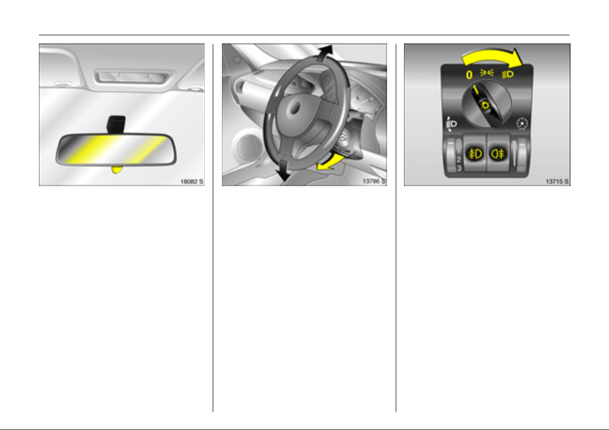
To adjust interior mirror by
swivelling
Swivel lever on underside of mirror housing
to red uce daz zle a t nig ht.
Mirrors 3 33.
Steering wheel adjustment 3:
Sw iv el le v e r down, ad ju s t heig ht,
swivel lever up, engage
Ad jus t stee ri ng wheel only when veh icle i s
stationary and ste ering column lock is
re l ea s e d.
Airbag systems 3 3 54.
Exterior lights
Turn light switch
7 =Off
8 = Parking lights
9 = Dipp ed b eam or main be am
Press light switch
0 = Courtesy light
Push button
> = F r o nt fo g l i ghts 3
r = Fog tail light
Lighting 3 8 0, Headlight warning de vice
3 78.
Page 11
7In Brief
Headli ght fl ash, m ain beam and
dip ped beam
Headlight flash = Pull stalk toward s
steering wheel
Main be am = Push stalk forwards
Dipped beam = Push stalk forwards
again
Main be am, headlight flash 3 81 .
Switch turn signal on
Right = Stalk upwards
Left = Stalk downwards
Turn signals 3 81.
Hazard warning lights
Operated with the ¨ button.
Hazard warning flashers 3 82.
Page 12
8In Brief
Page 13

9In Brief
Page
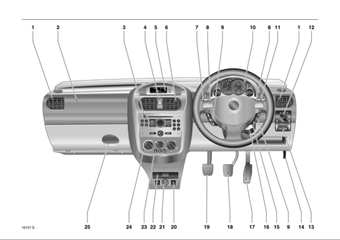
1 Side air v ents ... ..... .... ......... ......... .. 3 89
2 Front passenger airbag 3 .... ..... .. 3 54
3 Infotainment system 3 . .... .... ..... .. 3 86
4 Haza rd warn in g lights .. .... .... ......... 3 7
LED for Vauxhall
alarm system 3 ........ ..... .... .... ..... ... 3 30
5 Display 3 for time, date,
outside temperature,
infotainmen t system 3 ..... .... ..... .. 3 73
6 Centre air v ents ........ ......... ......... ...3 89
7 Turn signals, headlight fla sh,
dipped be am, main beam .. 3 6, 3 80
8 Horn .... .... ..... .... ..... .... ..... .... .... ..... ... 3 11
9 Steering wheel remote control 3 .3 86
10 Instrume n ts ...... ..... .... ..... .... .... ..... .. 3 63
Pa ge
11 Windscreen wiper,
windscreen wash system,
rear w in dow w ash sys tem 3 ........ 3 78
12 Light s witch ..... ......... ........ ..... 3 6, 3 80
13 Headlight range adjustment 3 ... 3 83
Fog tail lig ht .... .... ......... ......... ....... 3 82
Front fog ligh ts 3 ..... ........ ......... ... 3 82
Instrument illumination ........ ....... 3 83
14 Bonne t rele ase lever ..... .... ..... .... . 3 121
15 Starter switch with
Stee ring co lum n lock ... ......... ....... 3 14
16 Stee ring whee l adju stm ent 3 ........ 3 6
17 Accele ra tor pedal .... .... .. 3 102, 3 104
18 Brake peda l ......... ..... .... .. 3 102, 3 111
19 Clutch ped al 3 .... ..... .... .... ..... .... . 3 102
Page
20 Seat heating 3 ... ..... .... ..... .... ..... ... 3 38
21 Accessory socket or
cigarette ligh ter ...... ......... ......... ... 3 59
22 Ashtray 3 ............ ..... .... ......... ........ 3 60
23 Air conditioning system 3 ... ..... ... 3 92
Heated rear window 3 .... ... 3 12, 3 35
Air recirculation system 3 ......... ... 3 93
24 Heating and v entilation system . 3 88
25 Glove compart me nt ... ......... ........ 3 61
Page 14

10 In Brief
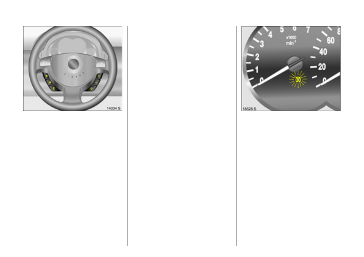
Control indicators
>
A
Z
v
Front fog lights 3,
3 63, 3 82 .
Engine electronics,
Immob iliser 3, E as ytr oni c3,
Fault,
3 19, 3 63 , 3 109.
Exhaust gases 3,
3 64, 3 109.
Airbag systems 3,
Belt tensio ne rs ,
3 64, 3 48 , 3 57.
I
O
C
!
T
r
Engine oil pressure,
3 64 .
Turn signal lights,
3 65 , 3 81.
Main bea m,
3 65 , 3 81.
Preheating 3, diesel p article
filt er 3,
3 65 , 3 110.
Winter programme of
Easytronic 3,
3 99 .
Fog tail light,
3 66 , 3 82.
p
R
u
S
EPS
Y
Alternator,
3 66.
Brake system,
clutch system 3,
3 66, 3 168.
Anti-lock brake system (ABS) 3,
3 112.
Engine oil level 3,
3 67, 3 164.
Electric power steering (EPS) 3,
3 67.
Fuel leve l,
3 67, 3 107.
Page 15
11In Brief
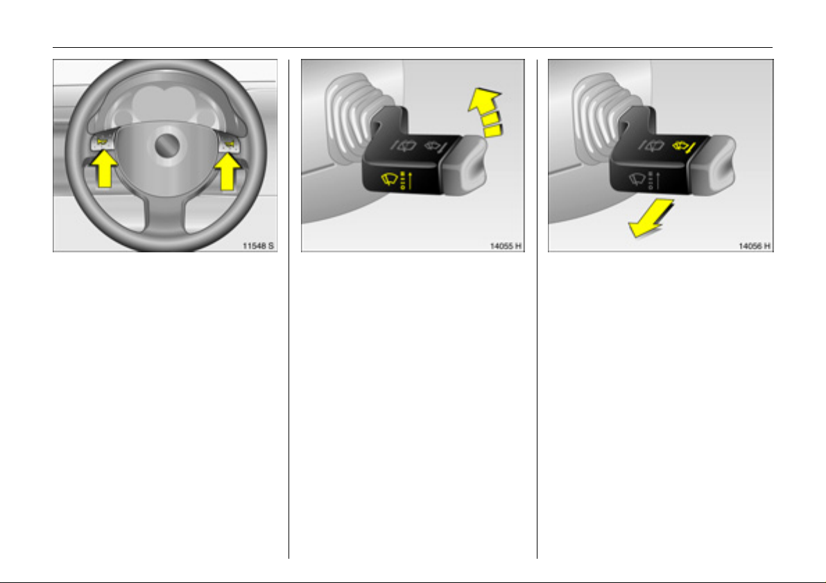
Op era te h or n : Pr es s j right or left
Airbag system 3 3 54, Remote control on
steering wheel 3 3 86.
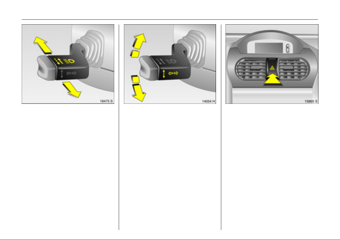
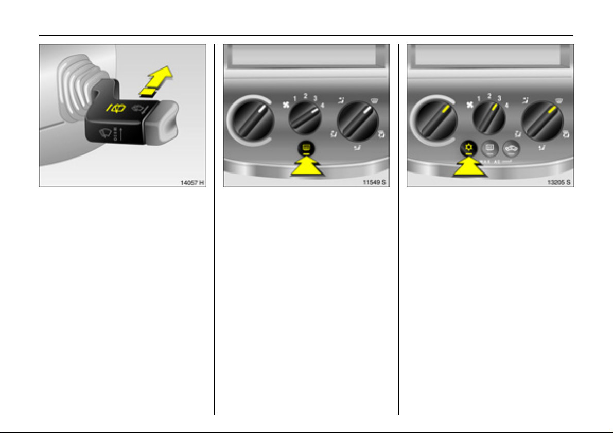
Windscreen wiper: Move stalk
upwards
& =Fast
% =Slow
$ = Ad justable interval s witching
§ =Off
Windscreen wiper 3 78, Adjustable wiper
interval 3 3 79, Further information 3 154,
3 168.
Operating windscreen wash
system: Stalk toward steering
wheel
W in dscr e en w ash s ystem 3 78, Further
inform ation 3 169, 3 182.
Page 16
12 In Brief
Rea r win dow wiper 3 and
Rear window wash system 3
operation
Wiper on = Push stalk forwards
Wiper off = Stalk toward steering whe el
Washing = Push sta lk forward and hold
Rear window wiper and rear window wash
system 3 78, Further information 3 168,
3 169.
Heated rear wind ow 3 , heated
exterior mirrors 3
Operated with the Ü button.
Climate con trol system 3 88, H eat e d rea r
wind ow 3 35 .
To clear fogged or icy windo ws
Turn th e rotary k no bs for te mperature an d
air flow clockwise. Set air distribution to V.
Air conditioning system 3: Also press
button n.
Climate control 3 3 88.
Page 17
13In Brief
Before starting off, check
z Tyre pressure and tyre condition 3 114,
3 179,
z Engine oil le vel and fluid levels in engine
compartment 3 163 to 3 169,
z All windows, mirrors, exterior lig hting
and nu mber plates are free from dirt,
snow and ice and operational,
z Seats, seat be lts and mirrors are
correctly a djusted 3 36, 3 46, 3 32,
z Check brake function at low spe ed,
particularly if the bra kes are wet.
Manual transmission
Reverse gear: With the vehicle stationary,
lift the ring under the gear-lever knob
3 seconds afte r de pres sing the clutch, a nd
then engage the gear.
If the gear does not engage, put the lever
into neutral, release the clutch ped al and
depress again; then repeat gear selection.
Manual transmission 3 101.
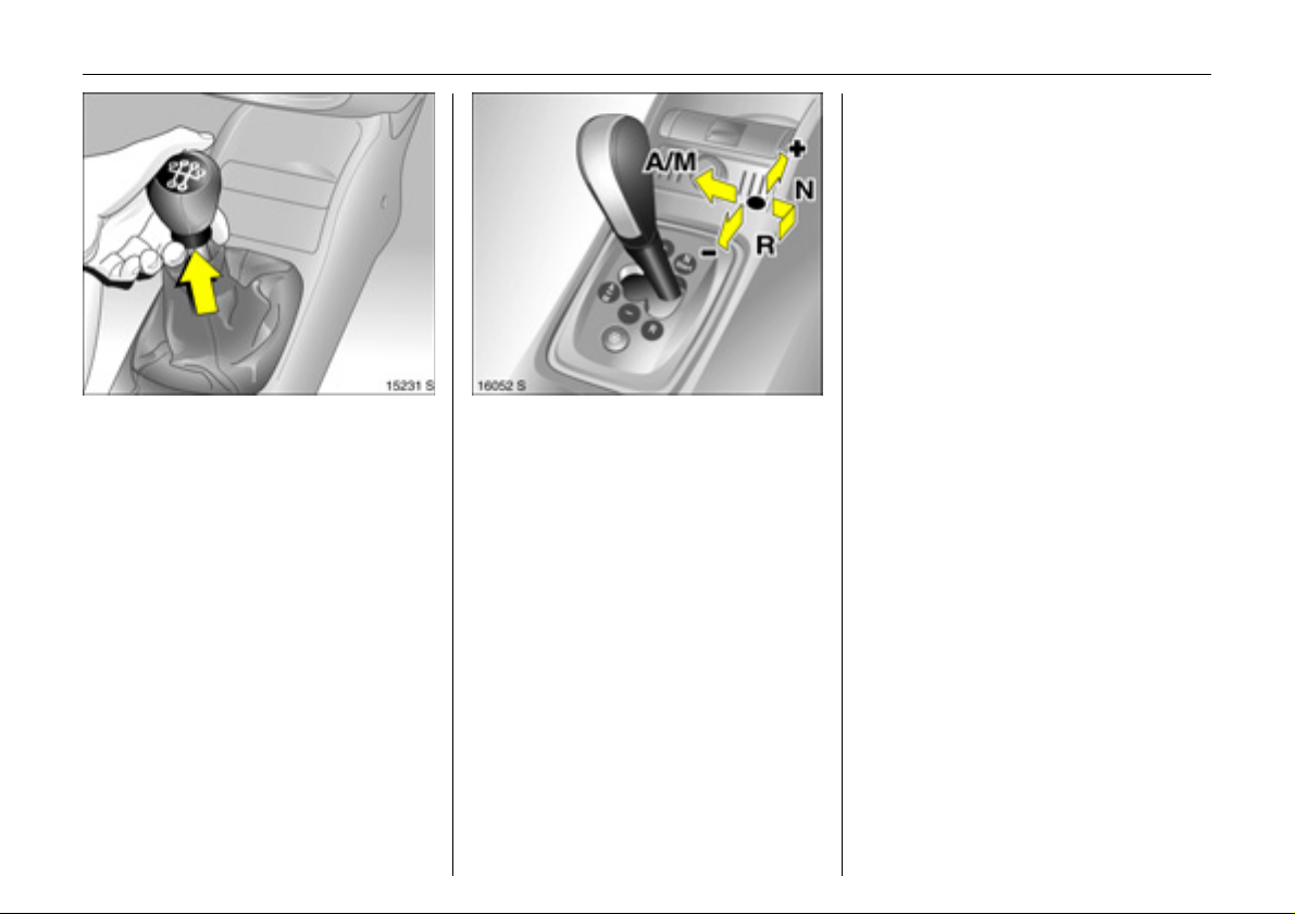
Easy tronic 3
N
= Idle spe ed/sta rt position
o
= Driv e position (centre position)
+
= Higher gear
-
=Lower gear
A/M
= Switch between Automatic and
Manual mode
R
= Reverse gear (w ith selector lever
lo c k )
To move the selector lever from N to R
pr es s th e b u t t o n o n th e l ev er .
Only start in N with foot brak e a pplied.
Eas yt ron ic 3 3 96.
Page 18
14 In Brief
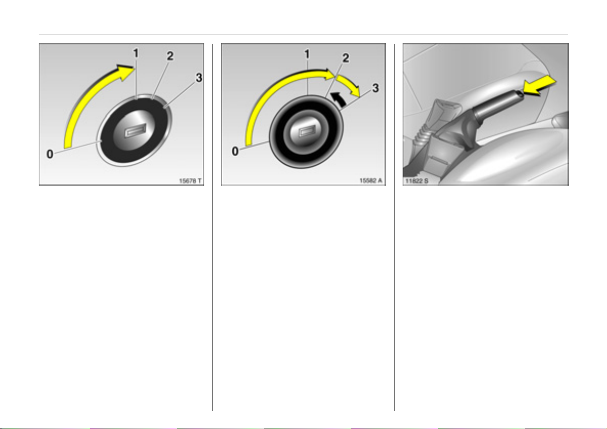
St e er ing c olum n lo ck and ignition
Turn key to position 1. Move the steering
wheel s lightly to release the steering
column lock.
0
= Ignition off
1
= Stee ring free, ignition off
2
= Ignition on,
with dies el engine: pr ehea ting
3
=Starting
Starting the engine
Depress the clutch and brake pedals,
Eas yt ron ic 3 in N , do not acc elerate; fo r
diesel e ngi n e, tu r n ke y to p ositio n 2; w hen
control indicator ! goes out turn the key
to position 3 and re lease it w hen the engine
is running.
To re peat the start proce dure or switch off
the e ngine, turn the key back to 0.
To switch on the ignition, turn the key to 2.
To release the handbrake: Raise
le ver s lig ht ly , p res s r ele ase
button, lower lever fully
Hand brake 3 66, 3 113.
Page 19

15In Brief
Parking the vehicle
z Always apply ha ndbrake firmly without
op erating the release button, and apply
as firmly as possible on a downhill or
uphill slope.
z Switch off the eng ine and ignition by
turning the ignition key to 0 and
removing it. Turn the steering wheel until
you can feel its loc k engage (anti-theft
protection).
On vehicles with Easytronic 3, control
in d i ca to r R flashes for a few seconds
after the ig nition is switched off if the
handbra ke has not been applied.
z If the vehicle is parked on a level surface
or an up hil l s lo p e, wit h a m anual
gearbox select first ge ar or with
Eas yt ronic 3 move the selector le ver to
the ce ntre position before switching off
the ignition. Also turn the front wheels
away from the kerb if the vehicle is on an
uphill slope.
If the ve hicle is on a d ownhill slope, with
manual gearbox or Easytronic 3 se lect
reve rse ge ar before switching off the
ig nition. Also turn the front wheels
to w a rd s th e ke rb .
z Lock the vehicle with the key in the lock
or the p button on the remote c ontrol.
Activate the anti-theft locking system 3
and V auxhall alarm system 3 by
pressing the p button twice.
Advice when parkin g
z Do not park vehicle on easily ignitable
surfaces as the hot exhaust system
temperatures could cause the surface to
ignite.
z C lose windows.
z The engine cooling fans may run after
th e e ng in e ha s been sw itched o ff, 3 163.
Locking doors 3 20, Re mote control 3 3 21,
Central lock ing sy stem 3 3 22, Vauxhall
alarm system 3 3 29, Vehic le
decommissioning 3 170.
Interesting functions
See following p ages.
6
Page 20
16 In Brief
Airbag system
The a irbag system consists of several
internal systems.
Front airb ag system 3
The front airbag system will be triggered in
the eve nt of a serious ac cident involving a
frontal impact and forms safety cushions
for the driver and front passenger. The
forward moveme nt of the drive r and front
passenger is checked and the risk of
injuries to the uppe r body a nd head
thereby substantially reduce d.
Side airb ag system 3
The side airbag s ystem trigge rs when a
side-on collision occurs and provides a
safety barrier for the driver and/or
passe nger in the respective front door
area. This reduces the risk of injury to the
up per body considerably in case of a side
impact.
Airba g Sy ste m 3 54.
Operating via the information
display menus
Th e menu opti ons a re sele cted via t h e
menus and with the button/four-way
button or the multi-func tion b utton of the
info ta inm ent system 3 or via the buttons 3
on the steering wheel. The menu options
app ear o n the displ a y.
To select with four-way button:
P r es s four-way bu t t o n up , d o wn , righ t o r
left.
Page 21
Selecting with the multi-function button
(adjuster wheel via the four-way rocker
switch 3 74):
Press and turn multi-function button.
To exit a menu, turn the multi-function
button left or right to Return or Main and
select.
To select with steering wheel buttons 3:
Select menu options via the menus using
the buttons.
Information display 3 73.
17In Brief
Di es e l p artic le fi l ter 3
The diesel particle filter system filters
ha rm ful soot particles out of the exhaust
gases. The system includes a self-cleaning
function that run automatically during
driving. The filter is cle aned by burning off
the soot pa rticles at high temperature. This
process ta kes place automatically unde r
set driving conditions and may ta ke up to
25 minutes. Fuel consumption may be
higher during this period. The emission of
smells and smoke during this process is
normal.
Under certain driving conditions, e.g. short
distances, the system cannot clean itself
automatically. If the filter requires cleaning and previous
driving c onditions did not enable
automatic cleaning, control ind icator !
flashes.
Further instructions 3 110.
Page 22
18 Keys, doors, windows
Keys, doors,
windows
Re placem ent ke ys ... ..... .... ......... ......... . 1 8
Key with retractable key blade 3 ..... . 1 8
Ca r Pass... .... .... ..... .... ..... .... ..... .... .... ..... . 18
Electronic immobiliser....... ..... .... .... ..... . 19
Mechanical unlocking or lock ing of
ind ividu al door s. .... ......... ......... ......... . 20
Remote control 3 . .... ..... .... ..... .... .... ..... . 21
Central locking system 3 ...... .... .... ..... . 2 2
Fault in th e rem ote co ntrol ... .... .... ..... . 2 4
Malfunction in central locking system 24
Sliding d oors 3 ......... ..... .... ..... .... .... ..... . 2 5
Child safety locks 3 . ..... .... ..... .... .... ..... . 2 5
Tailgate 3 ....... ..... .... ..... .... ..... .... .... ..... . 26
Rear doors 3 ........ .... ..... .... ..... .... .... ..... . 2 7
Vauxhall alarm system 3. ..... .... .... ..... . 29
Exterior mirrors ..... .... ......... ......... ......... . 3 2
Interior mirror ....... .... ..... ......... ........ ...... 3 3
Manual window operation,
front do ors .... ..... .... ..... .... ..... .... .... ..... . 33
Window in the sliding doors 3.. .... ..... . 3 4
Ele ctric w ind ows 3 ... ..... .... ..... .... .... ..... . 34
Heated rear window 3 ..... ..... .... .... ..... . 35
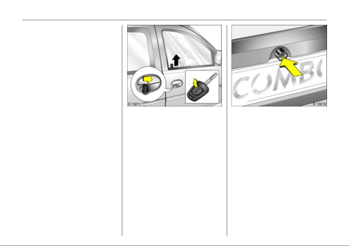
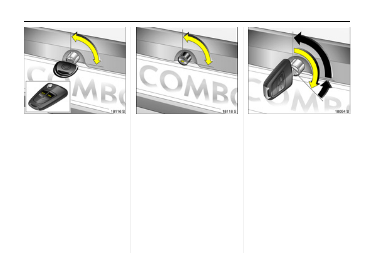
Replacement keys
The key numbe r is specified in the
Car P ass 3.
The key is part of the electronic
immobiliser.
Locks 3 20, 3 155.
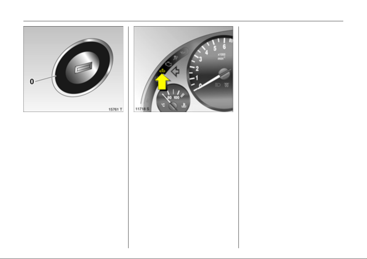
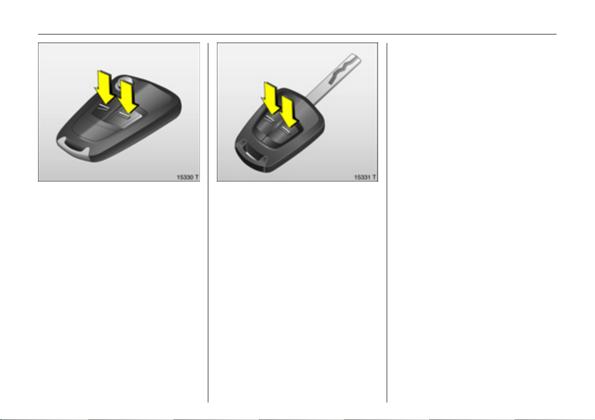
Key with retractable key b lade 3
Press button to extend. To retrac t, press
button and audibly engage key b lade.
Car Pass
The Car Pass contains safety-related
ve h icle d ata an d should ther efore be k ept
in a safe place.
When the vehicle is taken to a workshop,
the Car Pass data is needed in order to
perform certain operations.
Page 23
19Keys, do ors, windows
If control indica tor A illuminates afte r the
engine has started, there is a fault in the
engine electronics or Easytronic
transmission 3 100.
Not e
The immobiliser does not lock the doors.
You should always lock the vehicle after
leaving it and switch on the Vauxhall alarm
system 3, 3 20, 3 22 , 3 29.
Electronic immobiliser
Th e sys tem chec k s wheth er th e veh icle is
allowed to sta rt with the key used. Once
the transponder in the key is recognised,
th e v ehicle ca n be starte d.
The electronic immobiliser activates
automatically when the key is removed
from the starter switch.
Control i nd icator for imm obilise r A
Con trol indica tor A illuminates briefly
afte r the ig nition is switc hed on.
If the control indicator flashes when the
ignition is on, there is a fault in the system;
the engine cannot be started. Switch off
the ignition and then repeat the start
attempt.
If the control indicator A continues to
flash, please try to start the engine using
the second key and contact a workshop.
Page 24
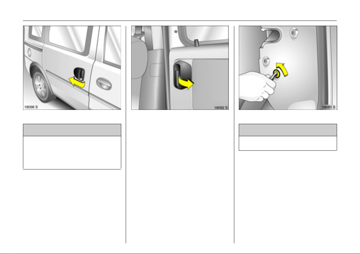
20 Keys, doors, windows
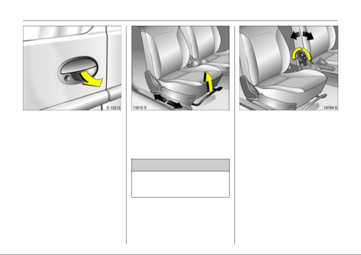
Mechanical unlocking or lo cking
of individual doors
(versions without remote control 3 and
central lock ing system 3)
Front doors and sliding doors 3
To unlock
Turn key in lock towards front of vehicle as
far as it will go. Return key to the vertical
position and remove. Pull door handle.
To lock
With door or sliding door closed, turn key
towards rear of vehicle as far as it will go.
Turn key back to vertical position and
remove.
Operating from the inside
Pull or press the interior lock button.
Ta ilgat e 3
To un l o c k
Turn key in lock to horizontal position and
remove. Press button.
To l oc k
With tailgate closed, turn key in lock to
vertical position and remove.
Rear door 3
To unlock
Turn key in lock to v ertical pos ition and
re m o v e. Pul l d o or ha nd l e .
To lock
Close first left and then right rear door.
Tu rn key in lo ck to horizo n tal positio n an d
remove.
Page 25
Remote control 3
Depending on the equipment of the
vehicle, one of the remote controls
depicted on this page will be u sed.
The remote control is integrated in the key.
Us ed to op er ate :
z Central locking system 3,
z mechanical anti-theft locking system 3,
z Vauxhall alarm system 3 .
O n veh icles wi th e lectro n ic win dows 3, t he
windows can be closed from the outside
using the remote control 3 35.
The remote control has a ra nge of approx.
5 metres. This range can be affected by
outside influences. Aim the remote control
at th e v ehicle to op erate . T h e h aza rd
warning lights flash to confirm remote
control operation.
Handle the remote control with care,
protect it from moisture and high
temperatures and avoid unnecessary
op er at io n .
21Keys, do ors, windows
Fault
If the central locking system can not be
operated with the remote control, it m ay be
due to the following:
z Ran ge exce ed ed.
z Battery voltage of the radio re mote
control too low, change batte ry.
z Frequent, repeated operation of the
remote control outside the reception
rang e of the vehicle (e.g. too far from
vehicle, remote control is then no longe r
recognised). Synchronise the remote
control.
z If the central locking system is
overloaded as a result of re peated
operation at s hort inte rvals. The power
supply is cut off for a brief period.
z Interference from higher-power radio
wa ve s from ot h e r source s.
Manual unlocking or locking with the
vehicle k ey 3 24.
Page 26
22 Keys, doors, windows
Re mote contr ol batt ery r e pla c em en t
Replace the battery as soon as the range
of the remote control begins to shrink.
Batteries do not belong in household
was te. They must be disposed of at an
appropriate recycling collection point.
Key with foldaw ay key section
Extend the key 3 18. Open the remote
control. Replace the battery (battery type
CR 20 32), noting installation position.
Close the remote control and synchronise.
Key with f ixe d key sec tion
Have the battery changed in a work shop.
Radio remote control synchronisation
Afte r changing the battery, unlock the
door with the key in the lock 3 24. Inserting
the key in the ignition synchronises the
re mo t e c o nt r o l .
Central locking system 3
Used to unlock and lock doors, sliding
door 3 , load compartment and tank flap
3 .
To unlock
Press button q on the remote control
– or from the inside –
Pull lock button on driver’s door.
When the mechanical anti-theft locking
system 3 is enabled, the doors cannot be
unlocked by pulling up the lock buttons.
Country-specific version 3: Pressing the
button once will unlock the driver’s door.
Pressing the button twice will unlock the
entire vehicle.
Page 27
To lock
Close doors, sliding door 3, load
compartme nt and tank flap .
Press button p on the remote control
– or from the inside –
Push the lock button on the driver’s door
wh en the do o rs ar e clo s ed.
Mechanica l anti-t heft locking sys tem 3
9 War ni ng
Do not us e the sy ste m if the re are pe op le
in the v eh icle! T he d oors can n o t be
unlocked from the inside.
All doors must be closed.
If the ignition was on, the d river’s door
must be opened and closed once so that
the vehicle can be secured.
All doors are secured against op ening.
Within 10 seconds of locking,
press the p button on the remote
control again
The mechanic al anti-theft locking system
switches off when the vehicle is unlocked.
23Keys, do ors, windows
Not e
z T o pr eve nt th e driv er from be ing
ina dvertently locked out, the button on
the driver’s door cannot be depressed
wh en the d oor is ope n.
z If the driver’s door is not closed properly,
the central locking system will unlock
again immediately after lock ing.
z A short time after unlocking with the
remote control, the doors lock again
automatically if no door is opened.
z To lock the d oors from inside (e.g. to
prevent unwanted entry from outside),
push down lock button on driv er’s door.
z Locked doors unlock automatically in
the event of an a ccident of a certain
severity (to permit outside assistance).
For this reason, the ignition must not be
switched off.
z If a sliding door 3 is o pe n wh en th e
vehicle is being locked, it is locked a few
se con ds afte r it has be en cl o s ed.
Page 28
24 Keys, doors, windows
Fault
If the central locking system can not be
operated, the problem may be as follows:
z If the central loc king sy stem is
ov erloaded as a re sult of re peated
op eration at short interv als. The power
supply is cut off for a b rief period.
z Defective fuse in the fuse box 3 140.
Please contact a workshop to have the
cause of the fault remedied.
O perate the driv er’s door with th e k ey.
Fault in the remote control
To un l oc k
Turn key in d riv er’s door lock towards front
of vehicle, turn back to vertical position
and remove. The entire vehicle is unlocked.
Switch on ignition to d eactivate V auxhall
alarm system 3.
To lock
With th e driver’s doo r cl os ed, tu rn key in
lock towards rear of vehicle, turn back to
vertical position and remove. The entire
vehicle is lock ed.
Malfunction in central locking
system
To unlock
Turn the key in the driver’s door lock
towards the front of vehic le, turn it b ack to
the vertical position and remove. The
drive r’s door is unlocked. The other doors
can b e ope ned b y pulling the lock button
(unless the anti-theft locking system 3 is
active). The load compartm ent and tan k
flap remain locked. Switch on the ignition
to deactiv ate the Vauxhall alarm system 3 .
To lock
With the driver’s door open, press the lock
bu t t o n of on e of th e ot h er door s . C los e the
driver’s door and turn the key in the driver’s
do or l ock towa rd t he rear of th e v ehicle,
turn it back to the vertical position and
remove. The unlocked fuel tank flap
cannot be locked.
Not e
z The me chan ical anti-theft locking
sy ste m 3 and the Vauxhall alarm system
3 cannot be activated with the key.
z To deactivate the Va uxhall alarm
sy ste m 3 alarm, switch on the ignition
after opening a door.
Page 29
25Keys, do ors, windows
Sliding doors 3
9 War ni ng
If the vehicle is parked facing down a
slope, open sliding doors m ay move
accidentally on account of their weight.
Close the sliding doors before driving
off.
Opening from outside
Unlock the door with the key b y turning it
forwards in the lock or p ressing the q
bu t t o n o n th e r em o te c o n t r o l .
To open the sliding doors, pull the handle
and slide the door towards the rear of the
vehicle.
Open ing from inside
To op en the unlocked sliding door, pivot
the handle and slide the door towards the
re ar of th e v eh ic l e .
To pre vent dam age, the right-hand sliding
do or can n o t be fully op en ed if th e tan k fla p
is open.
To clo s e
Slide the sliding door until it engages. To
lock the door, turn the key in the lock
tow ards the rear of the vehicle, press
button p on the remote control or press
the interior lock button.
Child safety locks 3
9 Warning
Us e the ch ild saf ety loc k w hene ver
children a re occupy ing the rea r seats.
With the sliding door open, use the key to
turn the rotary knob at the door lock from
the vertical position: the door c annot be
opened from the inside.
Page 30
26 Keys, doors, windows
Tailgate 3
To open
Turn the key in the lock to the vertical
position or press the q b utton on the
remote control.
Press the button to open the tailgate.
To close
Close the tailgate and turn the key in the
lock to a horizontal position or press the p
bu t t o n o n th e r em o te c o n t r o l .
Cen tral l oc king 3 and the ta ilgat e
The central locking system and a nti-theft
lock ing system 3 for the doors cannot be
op erated via the tailgate lock.
Key slot horizontal in lock
When the central locking system is
op erated, the tailgate is locked or unlocked
tog ether with the doors.
If the key is turned to the vertical position
after unloc king via the central locking
system, the tailgate re mains locked.
Ke y s l o t v er t i c a l in lo c k
The tailgate remains locked when the
doors are locked or unlocked via the
central locking system. Choose this position
if the tailgate is to always remain locked.
Unlock ing the ta ilgate with the key with
centra lly locked do ors 3
Turn the key clock wise as far as possible
beyond the resistance point from the
vertical or horizontal position. To
safeguard against being locke d out, the
ke y c annot be removed when in th is
position.
Relo ck the tailgate by clos ing it a nd t urning
the key to the horizontal or vertical
position.
In the horizontal position, the tailgate will
be unlocked the next time the vehicle is
unlocked via the central locking system .
Page 31

27Keys, do ors, windows
Rea r do ors 3
To open
Turn the key in the lock to the vertical
position or press the q b utton on the
remote control.
Open right-hand rear door from outside by
raising door handle or from inside by
pivoting handle.
Unlock and ope n the left-hand rear door
from inside by pivoting the handle.
The doors engage at a 90° p osition.
Both d oors can be opened up to 180°:
Close the door slightly from the 90°
position, disengage the stop lug from the
gu id e rail a nd o pen t h e door co mpl etely.
W hen th e doo rs are o pe n 18 0 °, th e rear
exterior lighting is covered. Therefore, only
op e n the d oors until they en ga g e when it is
dark outside.
When closing , mak e sure th at the sto p lu g
properly enga ges in the g uide rail.
To close
Push first the left and then the right rear
door pas t slig ht resistance. Turn the key in
the lock to the horizontal position and
remove or press the p button on the
remote control.
Page 32

28 Keys, doors, windows
Cen tra l locking 3 and the rear doors
The c entral locking system and anti-theft
locking system 3 for the doors cannot be
opera ted via the rear door lock.
Key slot vertical in lock
When the central locking system is
operated, the rear doors are locked or
unlocked together with the side doors.
If the key is turned to the vertical position
after unlocking v ia the central locking
system, the rear doors remain locked.
Key slot hor izontal in lo ck
The rear doors remain locked when the sid e
doors are locked or unlocked via the
central locking s ystem. Ch oose this pos itio n
if the re ar doors are to always rem ain
locked.
Notes on tailgate or rear doo rs
z After fitting certain accessories, it m ight
not be possible to keep the tailgate in
the open position.
z The number p late can only be seen when
the tailgate or rear doors are closed. Do
not driv e w ith a n op en tailgat e o r open
rear doors.
9 Warning
Do not drive with load c om partment
open when transporting bulky objects,
for e xample, since toxic exhaust fumes
could penetrate the interior.
Unlocking the rear doors w ith the key with
cent rally locked sid e d oors 3
Turn the key anticlockwise as far as
possible beyond the resis ta nce point from
the vertical or horizontal position and pull
the handle of the rear door. To safeguard
against being locked out, the key cannot
be remove d whe n in this position.
Relock the rear doors by closing them and
turning the key to the horizontal or vertical
position.
In the vertical position, the rea r doors will
be unlocked the next time the vehicle is
unlocked via the central locking system.
Page 33

Vauxhall alarm system 3
monitors
z the doors, load compa rtment, bonnet,
z the passenger c ompartment,
z vehicle tilt, e.g. if it is raised,
z th e i g ni ti on.
9 War ni ng
Do not activate the system if there are
people in the vehicle! The doors cannot
be unlocked from ins ide.
29Keys, do ors, windows
To activate
All doors, windows a nd the bonnet must be
closed. Press the p button on the re mote
control again within 10 seconds of locking.
If the ignition was on, the d river’s door
must be opened and closed in order to
activate the Vauxhall alarm system.
Act ivat ion without monitoring of
passenger comp artment and vehicle tilt
Switc h on if, for e xamp le, you wish to leave
animals in the vehicle.
1. Close load compartment and bonnet.
2. Pres s button in front of the c ourtesy light
(with ig nition off); LED in the hazard
warning light button flashes a maximum
of 10 seconds.
3. Close doors.
4. Switch on Vauxhall alarm system . LED
illuminate s. After approx . 10 seconds,
the system is ac tivated without
monitoring of the passenger
compartment or vehicle tilt. The LED
fla shes until the system is switched off.
Page 34

30 Keys, doors, windows
After the first 10 seconds of V auxhall alarm
sy st e m act iva t ion:
z LED flashes
slowly
z LED
illuminates
for approx.
1second
Contact a workshop for assistance if
problems are encountered.
=System switched on,
= Switch-off function.
Light e mit ting d iode (LE D)
During the first 10 seconds of Vauxhall
alarm system activation:
z LE D come s on
z LE D flash e s
ra p i dl y
=Test, delayed
swi tch -o n,
= Door, load
compartment or
bonnet open or
sys tem fault.
To deactivate
Press button q on radio remote control.
– or –
Switch on ignition.
If there is a fault in remote control, turn key
in driver’ s door lock toward front of vehicle
as far as it wil l g o. T hen turn key back to
vertical position and remove.
If the alarm is triggered when the driver’s
door is opened, deactivate the Vauxhall
al arm syste m by sw itc hing on the i gnition .
Page 35

Opening and closing the load
com partm ent 3 when the Vauxhall alarm
system is enabled
1. To unlock:
Ta ilg a te: Tu rn ke y clock wise all the way
past the horizontal position. The tailgate
is unlocked and monitoring of the
passenger compartm ent and vehicle tilt
are disabled.
Rear doors: Tu rn ke y a nticlo ckw ise all the
way past th e vertical pos ition. The rear
doors are unlocked and monitoring of
th e pas s enger co mpa rtm ent a nd vehicle
tilt are disabled.
2. O pen the tailgate or rear doors.
3. C lose the tailgate or rear doors.
4. To lock: Turn key back to ho rizontal or
vertical position. M onitoring of the
interior and vehicle tilt is enabled after
approx . 10 seconds.
31Keys, do ors, windows
Not e
z Modifications to the passenger
compartment, such as fitting seat
covers, could hinder the function of
passenger compartment monitoring.
z Switch off passenger com partment
monitoring of the interior of the parked
vehicle is being heated.
Alarm
When triggered, the alarm gives off an
acous tic signal (horn) and a visual signal
(hazard w arning flashers). The numbe r
and d uration of the alarms are stipulated
by legislation.
The alarm can b e silenced by pressing a
button on the remote control or by
switching on the ignition. The V auxhall
alarm system is deactivated at the same
time.
Page 36

32 Keys, doors, windows
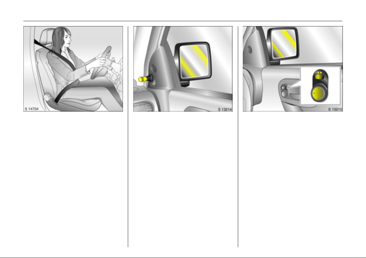
Exterior mirrors
A dju st m anually us i n g h an d les in t h e fr on t
doors or electrically 3 us ing switches in the
driver’s door console.
Manual exterior m irror adjustment
Adjust the exterior mirror using the handle.
Electrical exterior mirror adjustment 3
Select the corresponding exterior mirror
with the rocker switch and adjust with the
fo u r- w ay swi t c h .
Aspherical exterior mirror 3
The asph erical mirr or glass makes the blind
angle smaller. The curvature makes objects
look smaller, making it more difficult to
estimate how fa r away following vehicles
are.
To re trac t exterior mirrors
The exterior mirrors can b e folded in by
pressing gently on the outer edge of the
housing.
Return the mirrors to the driving position
before starting off.
For the safety of pedestrians, the exterior
mirrors will swing out of their norm al
mounting position if they are bumped with
sufficient force. Reposition the mirror b y
app lying slight p ressure to the mirror
housing.
Page 37

33Keys, do ors, windows
Heated exterior mirrors 3
Heating is activated or deactivated by
pressing the Ü b utton.
Heating is operable when the ignition is
switched on.
In terior mirror
Swivel mirror housing to adjust.
To reduce dazzle, swivel the lever on the
underside of the mirror housing.
Manual window operation,
front doors
T h e do or w i nd ow s c a n b e op erated u si n g
window winders.
Page 38

34 Keys, doors, windows
Window in the sliding d oors 3
z To op en
z To c l os e
= Release joint and push
outwards.
= Pull joint and e ngage.
Electric win dow s 3
9 Warning
Exercise care when operating electric
wind ows. Risk of injury, es pecially for
childre n.
Keep a close watch on the windows
when closing them. Ensure tha t nothing
becomes trapped in them as they move.
Operat ion al re adiness
Operational when the ignition ke y is in
position 1 in the starter switch.
Ill um ination of the rock er s witch es
indica tes operational re adiness.
Operational readin ess ceases when the
driver’s door is open.
Operation
To operate the window in stages, tap the
rocker switch. For automatic op ening or
closing , hold the switch pressed for slightly
longer; to stop wind ow movement, ta p
rocker switch again.
Safety function
If t h e win dow gl as s encou n te r s r es istan ce
abov e the mi ddle of t h e win dow d urin g
automatic closing, it is imm ediately
stopped and the w indow opened again.
If th e win dows do n o t mov e easi ly (e.g . due
to frost), repeatedly tap the rocker switch
for the window in question repeatedly until
the window has been closed in stages.
Page 39

Closing windows from the outside 3
Th e windo ws ca n be c lo s ed from the
outside using the remote control.
Hold the p button on the remote control
de pres se d until the fro n t windo ws are
closed.
Overload
If the windows are repeatedly operated at
short intervals, the power supp ly is briefly
cut off.
35Keys, do ors, windows
Fau lt
If the windows cannot be opened and
closed automatically, activate the window
electronics as follows:
1. Close doors.
2. Sw itch on ign it i o n .
3. C lose the window com pletely and hold
th e ro ck er switch de pres se d for at le ast
another 5 seconds.
4. O pen the window comple tely and hold
th e ro ck er switch de pres se d for at le ast
another 1 second.
5. Re peat for each window.
Heated rear window 3
Heating is activated or deactivated by
pressing the Ü button.
Heatin g is operable when the ignition is
switched on.
The heated rear w indow automatically
switc h es on wh e n the d ies el p ar ticle f ilter i s
being cleaned 3 depending on the engine.
Page 40

36 Seats, Interior
Seats, Interior
Front sea ts .. ......... ......... ......... ........ ...... 3 6
He ad re strain ts ........ ......... ......... ......... . 3 8
Load co mpartme nt ex tens ion ...... ..... . 4 0
Lashing eyes 3 ........ ..... .... ..... .... .... ..... . 42
Load compartment cover 3 . .... .... ..... . 42
Safe ty ne t 3 .... ..... .... ..... .... ..... .... .... ..... . 43
Load compartme nt grille 3 .......... ..... . 4 4
Not e s on lo adin g th e ve hic le .... .... ...... 4 5
Th ree-stage safety sy ste m.... .... .... ...... 4 6
Th ree-po int s e at belts .. .... ..... ........ ...... 4 6
Be lt tension e rs. ..... .... ..... .... ..... .... .... ..... . 4 8
Operation of the sea t belts... .... .... ...... 5 0
Child restraint system 3 ........ .... .... ..... . 5 1
Mounting clips 3 for ISOFIX child
restra int sys tem s ... ..... ......... ........ ...... 5 3
Airbag s ys tem . ..... ......... ......... ........ ...... 5 4
Use of child restraint systems 3 ........ . 5 9
Cigarette lighter 3 ............ ..... .... .... ..... . 5 9
Accessory socket 3.. ..... .... ..... .... .... ..... . 5 9
Ashtray 3 .... .... ..... .... ..... .... ..... .... .... ..... . 6 0
Stowage co mp artm ents ... ..... ........ ...... 6 1
Extendable stow age trays 3 .... .... ..... . 6 2
Coin holder 3 .. ..... .... ..... .... ..... .... .... ..... . 6 2
Sun visors. .... .... ......... ......... ......... ......... . 62
Fron t sea ts
9 Warning
Never adjust seats while driving . They
may make uncontrolled movem ents.
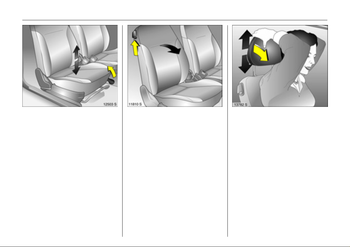
Adjust longitudinal seat position
Pull the handle at the front of the seat,
move the seat and then release the ha ndle .
9 Warning
Important: Do not sit nearer than
10 i nch es ( 2 5 c m) f rom the stee rin g
wheel, to pe rmit sa fe airbag
deployment.
Adjust ing the backrests
Take the pressure off the backrest and turn
th e ha nd wh ee l o n t he s i de.
Page 41

37Seats, Interior
Adj ust heig ht of s ea t
Lift lever a nd relieve som e weight from seat
to raise it or pr e ss down on se at with body
weight to low er it.
Ti lting the b ackres ts forwa rd
In order to fold the backrest forwards, lift
the release lever.
Seat pos ition
9 Warning
Only drive with the seat correctly
adjusted.
z Sit with your buttocks as far back against
the backrest as possible. Adjust the
distance be tween your feet and the
pedals so that your legs are slightly
angled when press ing the pe dals. Slide
the passenger seat as far back as
possible.
Page 42

38 Seats, Interior
z Sit with your shoulders as far back
against the backrest as possible. Set the
backrest rake so that you can easily
reach the steering wheel with your arms
slightly bent. Maintain contact between
your sh oulders and the backre st w hen
turning the steering w he el. Do not angle
th e ba c k res t t oo fa r b a c k. W e
recommend a m aximum ra ke of
approx. 25°.
z Ad ju st th e s tee rin g wh ee l 3 6.
z Set s eat he ight 3 high e n ough to have a
clear field of vision on all sides and of all
display instrume nts. The re should be a t
least six inch es o f clear an ce be twee n
yo ur he a d a nd t he hea d l i ni n g . Yo u r
thighs should rest lightly on the seat
without pre ssing into it.
z Adjust the head restraint.
z Adjust the height of the seat belt 3 50.
Hea ted front seats 3
Tw o pushbuttons ß in centre console.
With the ignition switched on, the heating
of the applicable front s eat is activate d by
pressing the button ß.
LE D ß on: the ap plicable front seat is
he at ed .
LE D ß off: heating of app lica ble front seat
is switched off.
Head restraints
Ad just ing the fro nt and outboard rea r
seat head restraint s 3
To adjust, hold head restraint at side, tilt
forward, hold a nd adjust height.
To improve visibility when the re ar seats
are unoccupied or to fold down a rear seat
or the front passenger seat, push the he ad
restraint all the way dow n or remove.
If the rear seats are occupied, adjust the
rear head restraints to the appropriate
level for the occupan t’s body size.
Th e op en fr ame head restr aint on th e
Combo Crew van cannot be adjusted.
Page 43

39Seats, Interior
Adj usti ng th e cent re re ar head re straint 3
To improve visibility when the ce ntre rea r
seat is not occ upie d or to f old the bac krest,
press the detent springs on the guide
sleeves to release the head restraint and
push it all the way down.
If the centre sea t is occupie d, set the head
restraint to the first or second position
according to the height of the passenger.
Head re straint position
9 Warning
Only drive with the head restraint set to
the proper position.
The middle of the head restraint should be
at eye leve l. If this is not possible for
extremely tall persons, set to the highest
position. Set to the lowest position for short
persons.
Removal - see page 3 39.
Removing the head restraint
Release both catches by pressing and
withdraw h ead restraint.
The rear, centre head restraint 3 ca nnot be
removed.
Not e
Only approve d obje cts or components
must be attached to the hea d restraint of
the unoccupied front passenger seat.
Page 44

40 Seats, Interior
Load c ompartment extension
Remove the load com partment cover 3 if
necessary 3 42.
Pull out the push-in collars 3 for the IS OF IX
child-restraint system mounting.
Closely follow the installation instructions
accomp anying the ISOFIX child restraint
system.
Folding down t he rear seat back rests
Push the rear, outer head restraint 3 down
completely or remov e it 3 38 . Push th e rea r,
centre head restraint 3 down completely
3 39.
To fold one or both of the rear seat
backrests, pre ss the button at the top to
relea se the backrest and fold it onto the
se at cu shion .
– or –
Remove the rear, outer head restraints 3
3 3 8. Push the re ar, centre head restraint 3
down com pletely 3 39 .
Hook seat belt buckles on rea r seat
bac krests.
Pull u p one or bo th re ar seat cushion s using
the straps provided.
Page 45

Repositioning the re ar se ats
Pull the seat belt slightly forward so that it
does not get damaged and audibly
engage th e backrests.
Reposition the seat cushions.
Insert outer rear head restraints 3.
41Seats, Interior
To fold one or b oth of the rear seat
Picture no: 12438s.tif
backrests, press the button at the top to
release the backrest (3 40, Fig. 18099 S)
and fold it forward.
Folding d own the fron t pa ss enge r s eat 3
Push the pas senger seat head res traint
down or remo ve it 3 38.
S lid e the front p assenge r seat back .
Fold front passenger s eat forward by
raising release lever.
Restoring the front passenger seat to an
upri ght pos iti on 3
Press the release lever forw ard, fold up the
front passeng er seat a nd audibly eng age.
Page 46

42 Seats, Interior
Lashing eyes 3
The four lashing eyes in the load
compartme nt that are shown in
Fig. 18101 S are used to secure objects that
are being transported so that they do not
slide around.
The brackets on the floor between the
front seats are only used to secure the
safety net 3 3 43. They must not be used
as lashing eyes.
Load compartment cover 3
Do not p lace any heav y or sharp-edged
ob jects on the cover.
To clo s e
Pull cover towards rea r of vehicle using
ha ndle and hook into side retain ers.
To op en
Unh ooke d th e c losed cove r at the re ar. It
rolls up automatically.
Remov ing
Open cover.
Press button at righ t side of cartridge and
engage by pushing right-hand e nd pie ce
to the left. Pull right side of cartridge out of
retainers, followed by left side.
Fitting
With cover rolle d u p, push the left s ide of
the cartridge into the retainer, followed by
the rig ht side.
Push button at rig ht end piece of cartridge,
and c artridg e engages.
Page 47

43Seats, Interior
Safety net 3
Passengers must not be carried behind the
safety ne t.
The safety net can be fitted behind the rear
seats or, with the rear seat backre st folded
down, behind the front seats.
Remove the load c ompartment cov er as
necessary 3 42.
Unroll the safety net.
Fitting behind the re ar sea ts
There are two installation aperture s in the
ro o f fram e ab ove t h e re ar s eats : Op en the
cover. Engage one side of the up per ne t
rod in one side, extend the rod and engage
in the other side. Close the cover.
Fold d own both rear seat backrests.
Hook tensioning straps into lashing eyes in
floor and tighten by pulling on the loose
end o f th e strap.
Reposition a nd engage the backre sts.
Fitting behind front seats
Pull up b oth rear seat c ushions and fold
down rear seat backrests.
Open the cover of the installation
apert u res in th e roo f frame above the fr o nt
seats. Engage the net rod in one side,
exte nd th e rod and engag e in th e othe r
sid e . C lose t h e c o ve r .
Hook tensioning straps into brackets in
floor and tighten by pulling on the loose
end o f th e strap.
9 Warning
The bracke ts m ust not be used as
lashing eyes to prevent objects th at are
being transporte d from sliding around
3 42.
Remov ing
Swivel tensioning strap length adjusters
upward and unhook straps. Open the
cover. Unhook upper net rod and close
cover.
Roll the safety net.
Page 48

44 Seats, Interior
Load c ompa rtment grille 3
To pre vent vehicle occupa nts from bein g
injured by loose cargo, a load
compartme nt grille can be ins ta lled behind
the front seats.
Sp lit load comp artment g rille 3
To enlarge the load compartment, the
grille can be moved forwards on the front
pas se nger’s side .
Push the head restraint of the front
passenger seat down as far as it will g o
3 38 .
Til t f ront p ass en g e r’s sea t bac kr es t
forward by raising release lever and push
down to lock in position.
Engage lever on load com partment g rille
at top pos ition, as shown in Fig. 12506 S.
Engaging the lever prevents damage to
the front passenger’s seat.
Position load compartment grille above
retai n er i n front pa s se ng er ’s se a t bac kre st.
Lock load compartment g rille in retaine r.
To do so, engage lever at bottom position,
as show n in Fig. 12507 S.
9 Warning
The load compartment grille m ust
always be locked in one of the retainers
when the vehicle is in use, and the lever
must be engaged at its bottom position.
Page 49

45Seats, Interior
Notes on loading the vehicle
z Heavy objects in the load compa rtment
should be placed as far forward as
possible against the rear seat backrests
or, if the re ar seat ba ckrests are folde d
down, ag ainst the fro nt s eat back rests. If
ob jects are to be stacke d, the heavier
ob jects should be placed at the bottom.
z Secure heavy objec ts with lashing
straps 3 atta ched to las hin g eyes 3
3 42.
z When transporting objects with the
backrests folded down, install the safety
ne t 3 3 43.
z Close the load compartment cover 3.
z If the seat backrests are not folded down
when transporting objects in the load
compartment, the backrests must be
fully upright and e ngaged in position
3 40.
z Do not a llow the load to protrude ab ove
the upp er edge of the back rests.
z The warning triangle 3 and first-aid kit
(cushion) 3 must always be freely
acces sible.
z Do not place any objects in front of the
rear window or on the instrument pa nel.
z No objects must be placed in the area in
which the airb ags inflate, as they could
cause injury when the systems are
deployed.
z T h e lo ad m us t n ot o bs tr u ct t h e op era tio n
of the pedals, handbrak e and gear
selector, or hinder the freedom of
movement of the driver. Do not place
any unsecure d objects in the interior.
z Do not drive with load compartment
open when transporting bulky objects,
fo r ex ampl e , s ince to xic exh au st fu mes
could penetrate the interior.
z T h e paylo ad is the di ffer en ce be tw ee n
the permitted gross v ehicle weight
(identification plate 3 171) and the EC
kerbweig ht.
z To calculate the EC kerbweight, enter the
data for your vehicle on page 17 7.
z The E C kerbwe ight includes allow ances
for the driver (68 kg), load (7 kg) and all
fluids (tank 90% full).
z Optional equipment and accessories
increase the kerb weight.
z Weights and payload 3 177.
z Driv ing with a roof load increa ses the
sensitivity of the vehic le to cross-winds
and has a detrimental e ffect on vehicle
handling due to the vehicle’s higher
centre of gravity. Distribute the load
evenly and se cure it properly with
retaining straps. Adjust the tyre pressure
to the load conditions. Do not drive
faster than 75 mph (120 km/h). Check
and retighte n the s traps frequently.
Observe country-specific regu lations.
z The permissible roof load is 100 kg. The
roof load consists of the weight of the
roof rack plus the load carrie d.
z If objects are transported in the load
compartment, the split load
compartme nt grille 3 must a lways be
loc ked in one o f th e reta in ers an d th e
lever must be engaged at its bottom
position 3 44 .
z When stowing objects in the stowage
compartme nt above the front se ats,
secure ag ainst falling out.
Page 50

46 Seats, Interior
Three-stage safety system
Com prising:
z three-point seat belts,
z belt tensioners at the front seats,
z airbag systems for driver and front
passenger 3.
The three stages are activated in sequence
depending on the severity of the accident:
z The automatic s eat belt locking d evices
prevent the be lt strap from b eing pulled
out and thus ensure that the vehicle
occ upants are retaine d in their seats.
z Th e seat be l ts of the fro nt se ats a r e
pulled downwards at the be lt buckles.
This tightens the s eat belt, the occupants
are slowed down at an e arly stage of
vehicle deceleration and stress on the
body is red uced.
z The airbag s ystems are also triggered in
the event of severe accidents a nd form a
safety cushion for the occupa nts .
9 Warning
The airbag systems serve to supplement
the three-point se at belts and belt
tensioners. The seat belts must therefore
always be worn. Disregard of the se
instructions may lead to injurie s or
endanger life. Vehicle passengers
should be informed acc ordingly.
Carefully follow the instructions
accompanying the child restraint system.
Three-point seat belts
The seat b elts have an automa tic retractor,
so that the belt is spring tensioned and
always lies against the body .
Information on the correct seat position
3 37.
Th e b elt s are locked du ring hea vy
acceleration or deceleration of the vehicle.
This prevents the seat belt from extending,
keep ing the occupant in his or her s eat.
Page 51

47Seats, Interior
9 War ni ng
Faste n your se at be lt be fo re ea ch t rip .
In the event of an accident, persons not
wearing sea t belts endanger their fellow
occupants and themselves.
Seat belts are only designed for use by one
person at a tim e. The y are not suitable for
persons young er than 12 years of age or
smaller than 15 0 cm.
For childre n up to 1 2 yea rs of ag e, w e
recom mend the V auxhall ch ild restraint
system 3 51.
Checking the seat belts
From time to time, check the functionality
of all se at be lt system com ponen ts an d
check for d amage. Have damage d
components replaced. Have seat belts and
deployed b elt tensioners replaced in a
workshop afte r an accident.
Make s ure that seat b elts ar e no t da maged
or trapped by s harp objects.
Page 52

48 Seats, Interior
Belt tensioners
In th e eve nt of a hea d-on or re ar -end
collision of a certain se verity, the front seat
belts are pulled down at the buckles and
thereby tightened.
Actuati on of belt ten sioners
is indicated by illumination of control
indica tor v; see next column.
Trigg ered be lt tensioners must be replaced
by a workshop. Belt tensioners can only be
triggered once.
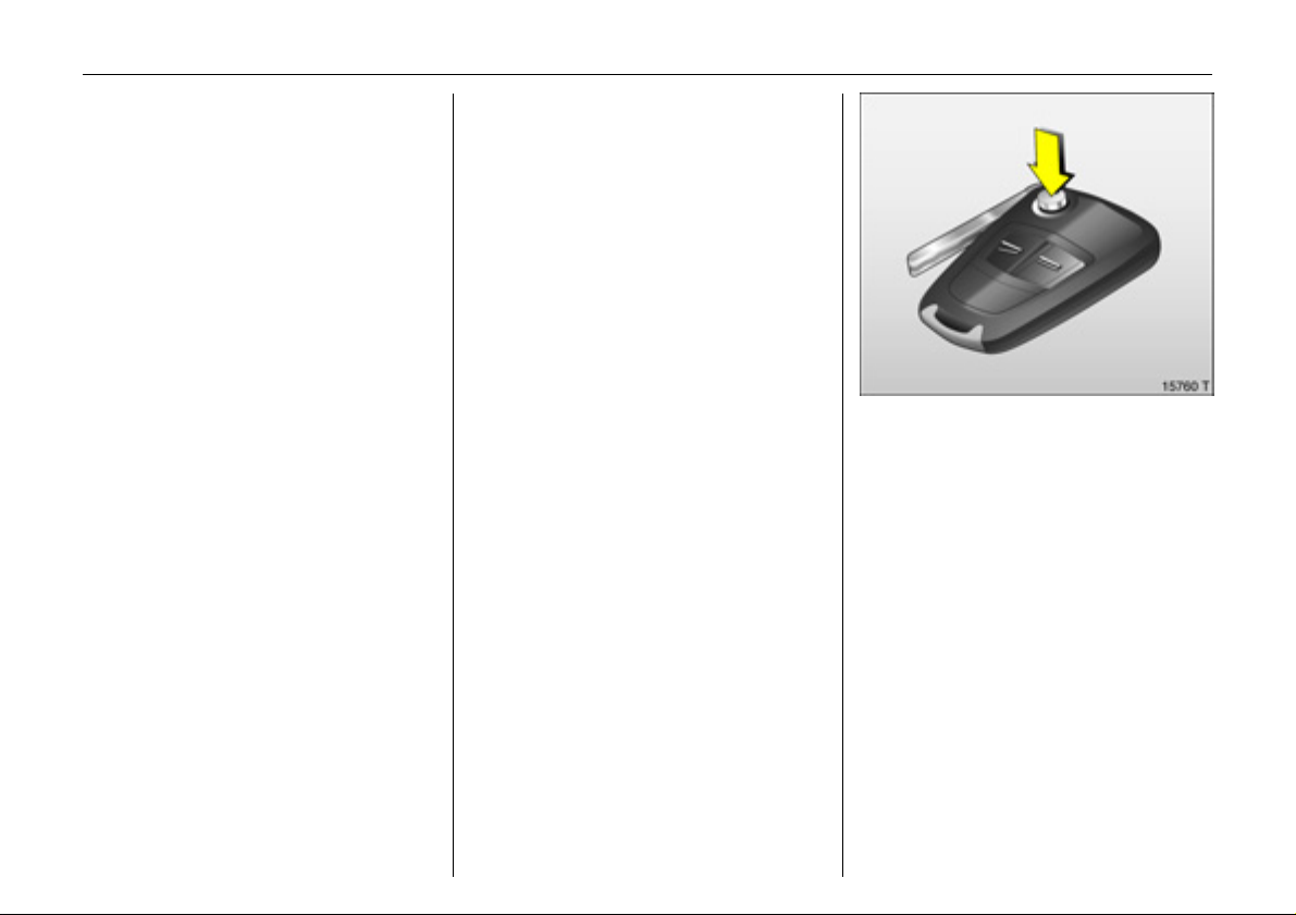
C ontrol in dic ator v for be lt tensioners
The functionality of the belt tensioner
system is monitored electronic ally together
with the airbag systems and indica ted via
control indicator v. When the ignition is
switched on, the control indicator come s on
for approx. 4 secon ds. If it does not com e
on, does not go out after 4 seconds or
comes on while driving, there is a fa ult in
the belt tensioner system or the airbag
systems 3 57. The systems may fail to
deploy in the event of an accident.
Triggered belt tensioners are indica ted by
steady illumination of v.
Page 53

49Seats, Interior
9 War ni ng
Hav e ca us e of fa ult r e m e died
immediately by a workshop.
The system’s integrated self-diagnostics
allows faults to be quickly remedie d.
Imp or tant
z Do not affix or place accessories or othe r
objects within the deployment zone of
the belt tensioners (in the area of the belt
buckle). Do not make any modifications
to belt tensioner components and the
inertia real device because this will
invalidate the vehicle type approval.
9 Warning
Incorre ct handling (e.g. removal or
fitting of seat belts or be lt buckles) can
cause the belt tensioners to deploy, with
ris k o f i n ju r y.
z The be lt tensione r and airbag system
control electronics can be found in the
centre console area. In order to avoid
malfunctions, do not store magnetic
objects in this area.
z When using the rear seat, m ake s ure that
the components of the front se at belt are
not damaged by shoes or other objects.
Not dirt must get into the inertia reel of
the s eat belt.
z We rec om men d th a t y ou ha ve t h e se a t s
removed by a w orkshop.
z The belt tensioners only deploy once,
which can be detected by illumination of
the control indicator v. Have de ploye d
belt tensioners repla ced by a workshop.
z The applica ble safety regulations must
be adhered to when the ve hicle is
disposed of. The vehicle should therefore
be disposed of by a recycling company.
Page 54

50 Seats, Interior
Operation of the seat belts
Fitting seat belts
The seat belt must not be twiste d and m ust
lie snugly against the body. The backrest
must not be tilted back too far (maximum
approx. 25°).
Adjust the height so th at the be lt lies across
the should er. I t must not lie across the
throat or upper arm.
Pull the belt out of the reel, guide it across
the b ody (mak ing certain it is not twisted)
and engage the latch plate in the buckle.
Tension the lap b elt frequently whilst
driving by tuggin g the should er belt.
9 Warning
On pregnant women in particular, the
lap belt must be positioned as low a s
possible across the p elvis s o as not to
put too much pressure on the abdomen.
Loose or bulky clothing prevents the seat
belt from fitting snugly. Do not place
ob jects such as handbag s or m obile
phones between the belt a nd your body.
9 Warning
The seat belt must not rest against hard
or fragile objects in the pockets of your
clothing.
Height adjustment
Adjusting the height of the upper
anchorage point of the front seat belts:
1. Pull out the seat belt s lightly.
2. Press b elt guide or push button down.
3. Set desired height.
4. Allow to lock audibly into p osition.
Do not adjust height while driving.
Page 55

51Seats, Interior
Remov ing the belt
To release the seat be lt, press the red
button on the be lt buckle.
Child restraint system 3
Follow the usage instructions for the child
restra int system.
Alw ays comply with local or national
regulations. In some countries, the use of
child restraint systems is forbidden on
certain seats.
Sele cti ng the right s y stem
Your child should b e tra nsported facing the
rear in the vehicle for as long as pos sible.
The very weak neck area of a child will be
under less stress in an accident if your child
is facing the rear and semi-horizontal, than
when they are sitting upright.
9 Warning
Child restra int systems must not be
carried on a pas senger’s lap. Da nge r to
life.
Page 56

52 Seats, Interior
Permissible options for fitting a child safety seat
Weight and
age cl ass
1)
On fron t
passenger seat
On an outboard seat in
the re ar row of seats
Group 0:
up to 10 kg
or approx.
10 months
XU+ U
Group 0+:
up to 13 kg
or approx.
2years
Group I:
9to18 kg
or approx.
XU+ U
8 months to
4years
Group II:
15 to 25 kg
or approx.
3to 7 years
XU U
Group III:
22 to 36 kg
or approx.
6to 12 years
On m iddle seat2) in
ther ear row of seats
X = Child restraint system s are not to b e
used on the front passenger seat.
U = universally suitable in c onjunction
with three-point seat belt.
+ = Vehicle seat with ISO FIX mounting
available. Only the ISOFIX child
restraint s ystem s that are approved
fo r the ve h ic le m ust be us ed w hen
mou nting with ISOFIX .
1)
We recommen d the use of each system u ntil the child reaches the upper weight limit.
2)
For reaso ns of safety , w e rec omm end that the c hild s afe ty seat be installed on one of the outer
rear seats.
Page 57

53Seats, Interior
Note
z Ch ildren under 1 2 ye ars of a ge or u n de r
150 cm tall must only travel in an
appropriate child restraint system on the
se ats in th e r ear row 3.
z When transporting childre n, use the child
restraint systems suitable for the child’s
weight.
z Be sure that child restraint systems are
properly installed - see the instructions
accompanying the child restraint
sys tem .
z The covers of the Vauxhall child restraint
system can be wiped clean.
z Do not stick anything on the child
res trai n t sy ste ms a nd do not co ve r t he m
with any other materials.
z O nly allow the child to enter and exit on
the side of the vehicle facing away from
the road .
z A child restraint system which has been
sub jected to stress in an accident must
be replaced.
z Secure or remove child restraint systems
that are in the vehicle but not in use.
Mounting clips 3 for ISOFIX child
restraint systems
The mounting eyes for the ISOFIX child
restraint system a re located on the rear,
outer seats 3 be tw ee n th e s ea t b a c k a nd
the seat cushion.
Fasten perm itted ISOFIX child restraint
systems to the mounting brackets.
Closely follow the insta lla tion instructions
acc ompanying the ISOFIX child restraint
system.
Page 58

54 Seats, Interior
Examples of events triggering the front
airbag system:
z Impact against a non-yielding obstacle:
the front airbags are triggered at low
vehicle speed.
z Impact against a yie ld ing obstacle:
(such as another vehicle): the front
airbags are only triggered at a higher
vehicle speed.
Airbag system
Front airb ag
The front airbag system consists of one
airbag in the steering wheel and one in the
instrument panel. These can be identified
by the word AIRBAG.
The front airbag system comprises:
z an airbag with inflator in the steering
wheel and a second one in the
instrument panel 3,
z the con trol elec tro n ics with impact
se ns or ,
z the control indica tor for airba g
sys tem s v in th e in st r u m e nt ,
The front airbag system will be trigg ered:
z depending on the severity of the
accident,
z de pending on the type of impact,
z within the range shown in Fig. 11734 S,
z independe ntly of the side airb ag
system 3.
The ignition must be switched on.
Page 59

55Seats, Interior
When trigg ered, the front airbags inflate in
milliseconds to form a safety cushion for
th e d riv er an d front pas sen ger . The
forward moveme nt of the front seat
occupants is checked, thereby
substantially reducing the risk of injury to
the upp er body and head.
No im pairment of view will occur, becau se
the a irbags inflate and de flate so quickly
that it is often not ev en noticed in an
accident.
9 Warning
Optimum protection is only provided
with the seat in the proper position 3 37.
Keep the area in which the airbag
inflates clear of obstructions.
Wear the three-point seat belt prope rly
fastened. The front airbag system is an
additiona l safety device, not a
replace ment for y our seat belt.
The front airbag sy stem will not be
triggered in the event of
z the ignition is switched off,
z minor frontal collisions,
z accidents in which the vehicle overturns,
z collisions involving a s ide or rear impa ct,
that is to say, if it w ould not be of benefit to
the oc cup ants.
Page 60

56 Seats, Interior
Sid e a irbag 3
The side airbag system consists of an
airbag in e ach fro nt s eat backre st. Th is can
be identi fied by th e wor d AIRBAG.
The side airbag system comprises:
z an airbag with inflator in the back of the
driver’s and front passenger seat
re s p ec ti ve l y,
z the con trol elec tro n ics ,
z the side impact sensors,
z the control indica tor for airba g
sys tem s v in th e in st r u m e nt .
The side a irbag system will be triggered:
z depending on the severity of the
accident,
z de pending on the type of impact,
z within the range shown in Fig. 13195 S on
the centre door p illa r of the driver’s or
front passenger side,
z indep endently of the front airbag
system.
The ignition must be switched on.
When triggered, the side airbag inflates in
milliseconds to form a safety cushion for
th e driver or fro n t pa s se n ger in the
respective door area. This substantially
reduces the risk of injury to the upper body
in the event of a s ide-on collision.
Page 61

57Seats, Interior
9 War ni ng
Keep the area in which the airbag
in fla tes c lea r of ob structio ns .
The side airbags will not be trigg ered in the
event of
z the ignition is switched off,
z frontal collisions ,
z accidents in which the vehicle overturns,
z collisions involving a rear im pact,
z collisions involving a side impact outside
the passenger cell.
9 Warning
Hav e c aus e of f ault re m e di ed
imm ediately by a workshop.
The system’s integrated self-diagnostics
allows faults to b e q uickly rem edied.
Control i ndicator v for airbag systems
The func tionality of the airbag s ystem s is
monitored electronically together with the
belt tensioner system and indicated via
control indicator v. When the ignition is
switched o n, th e co ntrol in dicator co mes on
for approx. 4 seconds. If it does not come
on, does not go out after 4 seconds, or it
comes on while driving, there is a fault in
the airbag tensioner system or in the belt
tensioner sy ste ms 3 4 8. Th e sy st e ms m a y
fail to deploy in the e vent of an accident.
Trigg ered airbag systems are indicated by
steady illumination of v.
Page 62

58 Seats, Interior
Im portant
z No o bjects or acce ssories mus t be placed
in the area in which the airbag s inflate,
as the y could ca use inju ry when the
com ponents are deployed.
z Do not place any objects between the
airb ag systems and th e vehicle
occupants. Danger of injury. Do not
install a child restraint system 3 on the
front passenger seat. Danger to life.
9 War ni ng
As with any other object, child restraint
systems must not be carried on a
passenger’s lap. Danger to life.
z Use the hooks in the roof frame only to
hang up light articles of clothing or c oat
hange rs. Do not place any objects in the
pockets of the hanging items – risk of
in j u r y.
z The airbag systems and belt tensioner
control electronics can be found in the
centre console area. In order to avoid
malfunctions, do not store magnetic
ob jects i n thi s ar e a.
z Do not stick anything on the steering
whe el, instrument panel or front s eat
backrests in the vicinity of the airbags.
Do not cover any of these areas with
other materials.
z Use only a dry cloth or interior cleaner to
clean the steering wheel, instrument
panel and front seat backrests. Do not
use any aggressive cleaning age nts.
z O nly protective covers whic h are
approved for y our vehicle with side
airbag may be fitted on the front seats.
W hen fi tting the protec tiv e cove r s, ma ke
sure that the airbag units on the
outboard sides of the front seat
backrests are not covered.
z The airb ag systems are triggered
independently of one another
depending on the severity of the
accident and type of imp act.
z E ach airbag is only de ployed o nce . Have
deployed airbags repla ced by a
workshop immediately.
z T h e s pee ds, d i rec tio n s of m ov em e nt an d
de form ation p rope rties of t h e v ehic les ,
and the properties of the obstacle
concerned, determine the severity of the
accident and triggering of the airbags.
The degree of damage to your vehic le
and the resulting repair costs alone are
not indicative that the criteria for
triggering of the airbags were met.
z Do not perform any alterations on the
components of th e airbag sy stem, as this
would render the vehicle unroadworthy.
9 Warning
If handle d improperly the airbag
systems can be trigg ered in an explosive
manner – risk of injury!
z We recom mend ha ving t h e s tee ring
wheel, the instrument panel, all panelling
parts, the door sea ls, the handles and
the seats removed by a workshop.
z The applica ble safety regulations must
be adhered to when the ve hicle is
disposed of. The vehicle should therefore
be disposed of by a recycling company.
z A nyone weighin g le ss th an 35 kg shou ld
seat in the rear seat.
Page 63

Use of child restraint systems 3
9 War ni ng
No child restraint system 3 may be
installed on front passenger seat.
Danger to life.
Child restraint systems must only be
installed on the se ats of the rear row 3.
On versions without rear row of seats, no
child re straint system m ay be installe d
on the front passenger seat.
59Seats, Interior
Cigarette lighter 3
The cigare tte lighter is in the centre
console.
With the ignition on, press in the cigarette
lighter. It switches off automatically when
element is hot. Pull out the cigarette lighter.
Accessory socket 3
Th e accessory soc ket is in t h e centre
cons ole.
The accessory socket or cigarette lig hter
socket can be used to connect electrical
accessories.
Th e socket is op erat io n al w hen the ignition
is s wi tc hed on. U s e of th e so ck et d i scha rg e s
the battery if the engine is not running.
Caution
Do not dam age the s ockets by using
unsuitable plugs.
Page 64

60 Seats, Interior
Do not exceed the maximum power
consumption of 120 watts.
Electrical acce ssories connected to the
soc ket must comply with the
electromagn etic compatibility
requirements la id down in DIN VDE 40 839,
otherwise vehicle m alfunctions may occu r.
Do not connect any curre nt-delivering
accessories, e.g. electrical charging
devices or ba tteries.
Ashtray 3
Caution
To be used only for ash and not for
combustible rubbish.
Fro nt a sht ray 3
Open the ashtray cover to the resistance
point.
To empt y, open the ashtray cover fully
beyond its resistance point, causing the
insert to lift. Grip both sides of the ashtray
insert and pull upwa rd s.
To e nlarge the storage compartment
remove the as htray comple tely.
Page 65

61Seats, Interior
Rear ashtra y 3
In the rear centre console.
To open, swivel the cover upwards.
To e mpty, lift the cover and pull the
ashtray out upwards by its cov er.
Stowage compartments
Glove comp artment
To op en, pull handle.
On the inside of the glove compartm ent
cover there is a pen holder.
The glove compartment should remain
close d while driv ing .
Stowage com partm ent for glasses 3
On driver’s side : fold down to open.
Page 66

62 Seats, Interior
Stow age com partm ent in roof abov e the
front seats and side mesh pockets above
the sliding doors 3
The stowage compartment above the front
seats can hold a maximum load of 1 5 kg.
The m esh packets above the doors can
only hold light objects.
9 War ni ng
Secure obje cts to prevent them from
falling out and causing injury.
Stowage compartment 3 beneath
passenger seat
Lift stowage c ompartment by grasping the
rece ss ed ed ge an d p ull it out . M aximum
loa d: 1 kg. To close the stowage
compartme nt, push it in and engage.
Extendable stowage trays 3
The extendable stowage trays are located
in th e fr o nt se at ba ck rests.
To unfold, p ull upward s until it e ngages.
To fold away, press downwards past the
re s i st an c e .
Do not play heavy objects on the tray.
Coin holder 3
In the centre console.
Su n v is ors
Use the sun visor to protect from glare by
pulling it d ow n and swivelling it to the side .
Page 67

Instruments
63Instruments
Con trol in dicators .... ..... .... ......... ......... . 6 3
Instrume n t dis play ........ ......... ........ ...... 6 8
Information display ...... .... ..... .... .... ..... . 7 2
Warning buzzers .. .... ..... .... ..... .... .... ..... . 78
Wind screen wipe r ......... .... ..... ........ ...... 7 8
Control indicators
The control indicators described he re are
not p resent in all vehicles. The description
applies to all ins trument versions.
The colours of the control indicators m ean:
z Re d
z Y ellow
z Green
z Blue
Dange r, important reminder,
Warn ing, inform ation, fa ult,
Switch-on confirmation,
Switch-on confirmation.
>
Front fog lights 3
Control indica tor illuminates green
Illum inates when the front fog lights are
on 3 82.
A
Engine electronics, transmission
electronics 3, imm obilise r, die sel fuel
filt er 3
Control indicator illu minate s and/or flashes
yellow
It illuminates for a few sec onds when the
ignition is switched on.
Illuminates when the eng ine is running
Fault in engine electronics or transmission
electronics. Electronics switch to
emergency running programme, fuel
cons umption may increase and driveability
of vehicle m ay be impa ire d 3 109. If the
fault is not remedied by re-starting,
contact a workshop for assistance
imm ediately.
In vehicles with diesel engines, it may be
nec es sar y to d rain th e d ies el f u el filt e r
3 166.
Page 68

64 Instruments
Flashes when the ignition is on
Fault in the e lectronic immobiliser system;
the en gine ca nnot be started 3 19.
Z
Exhaust emission
Control indicator illuminates and/or flashes
yello w
It illuminates wh en the ignition is switched
on and goe s out shortly after the engine
starts.
Illuminates when the engine is running
F au lt i n emis sion co n tro l syste m. Th e
permissible emission limits may be
exceeded. Contact a workshop for
assistance im med iately.
If it flashes when the engine is running:
Fault that c ould lead to cata lytic converter
damage. Ease up on the throttle until the
flashing stops 3 109. Seek the immediate
assistance of a w orkshop.
v
Airbag systems 3, Be lt t ens ion ers
Control indica tor illuminates red
Illum inates when the engine is running
Fault in the airbag or belt tensioner system
3 48, 3 57.
I
Engine oil pre ssure
Control indicator illuminates red
It illuminates w hen the ignition is switched
on and g oes out shortly after the e ngine
starts.
Illuminates when the eng ine is running
Caution
Engine lubrication may be interrupted.
Th is ma y result in damage to the e ngine
and/or locking of the drive whe els.
1. Move out of the flow of traffic as quickly
as possible without impedin g other
vehicles.
2. Depress clutch 3.
3. Set manual transmission to neutral, or
with Easytronic 3 place selector lever in
N.
4. Switch off ignition.
9 Warning
W hen th e engi n e is of f, con s idera bly
mo re f o rc e is n e ede d t o b ra k e an d st ee r.
Do not remove key until vehicle has
come to a standstill, otherwise the
steering column loc k could engage
unexpectedly.
Contact a workshop for assistance.
Page 69

65Instruments
The control indicator ! goes off as soon
as the self-cleaning operation is complete.
Diesel particle filter 3 110.
T
Winter programme of Easytronic3
An indicator light illuminates in the
transmission displa y if the Winter
programm e is activ ated 3 99.
O
Turn signal lights
Control indicator flashes green.
The con tro l indicator f lashes if a turn s ignal
or the hazard warning flashers a re
activated.
Rapid flashing: light or associated fuse has
failed.
Replacin g bulbs 3 144. Fuses 3 138.
C
Main bea m
Control indicator illum inates blue.
It is illuminated when main beam is on and
during headlight flash 3 81 .
!
Preheating 3, dies el part icle filte r 3
Control indicator illu minates a nd/ or flas he s
yellow
Illum inated
Preheating activated. Only activates when
outside temperatures are low.
Fla s h es
(in vehicles with diesel particle filter)
Con trol indica tor ! flashes if the filter
requires cleaning and previous driving
conditions did not pe rmit automatic
cleaning. Continue driving and if possible
do not allow engine speed to drop be low
2000 rpm.
Page 70

66 Instruments
r
Fog tail light
Control indicator illum inates yellow.
Illuminates when the fog tail light is on
3 82 .
p
Alternator
Control indicator illum inates red
It illuminates wh en the ignition is switched
on and goe s out shortly after the engine
starts.
Illuminates when the engine is running
Sto p a nd turn e ngine o ff . ba tte ry is not
charge d. Engine cooling may be
interrupted. Contact a workshop.
R
Brake system, clutch system 3
Control indicator illuminates or flashes red.
Illum inated
Illum inates when the ignition is switched on
if the handbrake is applie d 3 113.
Illum inates when the handbrak e is released
if the fluid level for the brake or clutch
sy ste m 3 is lo w 3 168.
9 Warning
Stop. Do not continue your journey.
Consult a work shop.
Fla s h es
On vehicles with Ea sy tron ic 3 , control
indica tor R flashes for a few seconds after
the ignition is switche d off if the handbrake
ha s not be en ap plied.
u
Anti-lock b rake system 3
Control indicator illuminates red
Illuminates while driving
Fault in the anti-lock brake system 3 112.
Page 71

S
Engine oi l level 3
Control indicator illum inates yellow.
The engine oil le vel is c hecked
automatically.
Illuminates when the engine is running
Engine oil level too low. Check engine oil
lev el and top up engine oil if necessary
3 164.
1)
EPS
Electric power steering 3
Control indicator illuminates yellow.
Fault in the electric power steering. It is still
possible to drive. Although it is still possible
to steer the vehicle, it is significantly more
difficult. Conta ct a workshop for
assistance.
67Instruments
Y
Fuel leve l 3
Control indicator illu minate s and/or flashes
yellow
Illuminates
Level in fuel ta nk too low.
Flashes
Fuel le vel is us ed up , f u el imm ediat e ly.
Never let the tank run dry!
Erra tic fuel s upply can cause the catalytic
converter to overheat 3 108.
Diesel engines: Bleed the fuel system if the
fuel tank is allow ed to run dry 3 121.
1)
EPS = E lectric Power Steering.
Page 72

68 Instruments
Vehicles with clock in odometer
To reset, press button with ignition
switched on a nd trip odometer activated
and hold d own for approximately
2seconds.
To switch between trip od ometer and clock
display 3 gi ve re se t kn ob a b r ie f p res s – se e
next page.
Bottom line:
Odometer
Records the number of miles.
Service interval display 3 162.
Instrument display
Tachometer
Displays the engine rpm.
Drive in a low engine speed range for each
gear as much as possible.
Caution
If the pointer is in the warning zone, the
maximum permitted engine spe ed is
exceeded. Engine at risk.
Sp eedometer
Spe ed display.
Mileage displ ay
With the ignition switched off, briefly press
the rese t knob to display the number of
miles driven for approx. 15 seconds.
Top line:
Trip odometer
Display s the number of m iles sin ce the
gauge was reset.
To reset, press button with ignition
switched on and trip odometer activ ated
and hold down for approxima tely one
se cond .
Page 73

Time di sp lay in odo meter 3
To switch between trip odometer and time
display 3 give reset button a short press.
W hen th e vehicle lights are on, th e
brightness of the display can be adjusted
using the right-hand adjuster wheel k
below the light s witch 3 83 .
69Instruments
Setting the time
On the clock display, press the setting knob
on the instrument for approx. 2 seconds.
The flash ing va lue is set b y pressing briefly.
Press for about 2 seconds again to switch
to the next setting and at the end to exit
setting mode.
Page 74

70 Instruments
For physical re asons, the engine
temperature gauge show s the coolant
temperature only if the coolant level is
adequate.
Durin g operat io n the s ys tem is pres suris ed.
The temp erat u re ma y th ere for e r ise briefl y
to ov er 100 °C.
Coola nt temperat ure display
Coolant temperature gauge.
Pointer in zone
at left
Pointer between
the zones
Pointer in right
zone (warning
zone)
= Engine operatin g
temperature not y et
reached
= Normal operating
temperature
= Temperature too
high : S to p th e
vehicle and switch
off the engine.
Danger to engine .
Check coolant level
immediately 3 166.
Fuel gauge
Control indicator Y illum inates when the
level is low. Refuel im mediately if the
control indicator begins to flash.
Never run the tank dry!
Because of the fuel remaining in the tank,
the amount of fuel required to fill the tank
may be less than the specified tank
cap acity.
Page 75

71Instruments
Transmission display 3
Display of cu rren t ge ar or mo de with
Ea sy tr onic 3 .
R Reverse gear
N Ne utral
A Automatic mode for Easytronic
1-5 Manual mode, current gear w ith
Easytronic
Ea sy tr onic 3 3 96.
Service di sp lay 3
If it illuminates in the odometer d isplay,
book vehicle into a workshop as soon as
possible for a service with maintenance .
Maintenance, inspection system 3 162.
Page 76

72 Instruments
12:01 17,0°C
FM 3 90,6MHz
REG AS RDS TP
Information display
Tripl e inform ation d isp lay 3
Display of time, outside tempera ture and
date/infotainm ent system (when it is on).
When the ignition is off, the time, date and
outside temperature can be displayed by
briefly pressing one of the two buttons
adjacent to the display.
FM [T P] C Din
90.6
MHz
19,5° 19:36
Graphica l Informa tion Display 3
Display of time, outside temperature a nd
date/infotainment system (when it is on).
The type of inform ation a nd how it is
displayed depe nd on the equipm ent of the
vehicle and the settings ma de.
Some information app ears in the disp lay in
an abbre viated form.
8:56 -5,5°C
:
07.04.2004
Outside temperature
A fall in temperature is indicated
imm ediately and a rise in temperature
after a time delay.
If outside temperature drops below 3 °C,
the symbol : app ears in t h e triple
inform ation display as a wa rning for icy
road conditions. When temperature
increases to at least 5 °C, the : sy mb o l
goes out.
Page 77

Slippery road
-2,5°C
OK
In vehicles with graphical information
display 3, Sl ippery road is shown in the
display as a warning for icy road surfaces.
Th ere is no messa ge b elow -5 °C .
9 War ni ng
Caution: The road surface may already
be icy even though the display indicates
a few de grees above 0 °C.
8:56 5,5°C
07.04.2004
Triple information display
Set dat e and tim e
The infotainme nt system 3 must be off.
Ac tivate se tting m ode by holding the Ö
button depresse d for about 2 seconds. The
flashing value is adjusted using the ;
button. The Ö button is used to switch to
the next unit and to exit setting mode.
73Instruments
Automatic time s ynchronisation 3
The RDS signal of most VHF transmitters
automatically se ts the time. This can be
identified by } in the display.
Some transmitters do not send a correct
time signa l. In such cases, we recommend
that you switch off automatic time
synchronisation.
Activate setting mode and set it to year
setting. Hold the Ö button depressed
about 3 seconds until } flashes in the
display and “RDS TI ME" appears. The
function is activated (RDS TIME 1) or
deactivated (RDS TIME 0) with the ;
button. Exit setting mode using the Ö
button.
Page 78

74 Instruments
FM [T P] C Din
90.6
MHz
19,5° 19:36
Gr a phica l informa tion d isplay 3,
selecting functions
The graphical information display depicts
func tions and their menus.
Functions are selected and executed in the
menu on the display using the four-way
button, the multi-function button 3 on the
infotainment system or the buttons 3 on
th e s t ee rin g wh ee l.
To sele ct w ith four-wa y but ton
Select menu items via menus and with the
buttons/four-w ay button of the
infotainment system.
To se lec t wit h multi-fun ct ion bu tton 3
Turn the multi-function button to highlight
menu items or comm ands and to select
function a reas.
Press the multi-function button to select the
highlighted item or confirm a command.
To e xit a m enu, turn the m ulti-function
button left or right to Return or Main and
select.
Page 79

FM [T P] C Din
90.6
MHz
19,5° 19:36
75Instruments
7777 Settings 19,5° 19:36
Time, Date 19:36
Language
Units 10 . 07 . 2004
Contr ast
Day / Night
6666 Ign. l ogic
To sel ect with steering wheel buttons 3
Select menu options via the menus using
the buttons.
Function ranges
Each function has a main page, w hich is
selected from the upper row of the display
(not in Infotainment system CD 30):
z Audio,
z Na vigation 3,
z Telephone 3.
For audio, navigation 3 and telephone
functions 3, see infotainme nt system
instructions.
System settings
The settings are accessed via the
Sett ings me nu.
Press the Main button 3 (not found on all
infotainment systems) on the infotainment
system (call up main display).
Press the Settings button on the
infotainment system. For Infotainment
system CD 30, no menu m ay be selected.
The Settings menu opens.
Page 80

76 Instruments
7777 Time, Date 19,5° 19:36
Time 19:36
Date 10 . 07 . 2004
6666 Synchron. clock automatical.
Setti ng date and time
Select menu item Time, Date, fr o m t he
Setti ng s menu.
The menu for Time, Date is displaye d.
Select the required menu item and make
setting.
Automatic tim e synchronisation 3
The RDS signal of m os t VHF transmitters
autom atic ally sets the time.
Some transmitters do not send a correct
time signal. I n such cases, we recommend
that you switch off automatic tim e
synchronisation.
On infotainment systems with
na vigation 3, time and date are als o
ha rmonised upon receipt of a GPS sa tellite
signal.
The function is activate d by ticking the fie ld
in front of Synchron. clock aut omatical. in
the Time, Date menu.
7777 Settings 19,5° 19:36
Time, Date
Language Deutsch
Units English
Contr ast Español
Day / Night Nederlands
6666 Ign. logic Français
Language selection
You can select the display language for
some functions.
Selec t menu item Language from the
Sett ings menu.
The available languages are dis played.
Page 81

77Instruments
7777 13 Languages 19,5° 19:36
X Deutsch
English
Español
Nederlands
Français
Italiano
Select the desired language.
Selections are indicate d by a 6 in front of
th e m enu item .
In systems with language version 3, when
the language setting of the display is
changed , the system will as k if the m essag e
language should also be changed - see
infotainment system instructions.
7777 Settings 19,5° 19:36
Time, Date
Language
Units
Contr ast
Day / Night
6666 Ign. l ogic
Setting unit s of measure
Select menu item Units from the Settings
menu.
The ava ilable units are display ed.
Select the desired unit.
Selections are indicated by a o in front of
the menu item.
~ Europe-SI
| Japan
| Great Britain
| USA
7777 Contrast 19,5° 19:36
12
Adjust contrast 3
Selec t menu item Cont ras t from the
Sett ings me nu.
The menu for Contr ast is disp layed.
Confirm the required setting.
Page 82

78 Instruments
Setti ng displa y mode 3
Display brightness is indepe ndent of
vehicle lighting. Settings are made as
follow s:
Select menu item Day / N ight from the
Setti ng s menu.
The options are displayed.
Autom atic: Adapted based on vehicle
lighting.
Alw ays da y des ign: Black text on light
background.
Alw ays night design: W h ite te xt on dark
background.
Selections are indicate d by a o in front of
th e m enu item .
Ig ni tion logic 3
Setting, see infotainment system
instructions.
Warning buzzers
When starting the engine or while driv ing:
z if seat b elt 3 is not fastened.
z If the sp eed programmed at the
factory 3 is exc eeded.
z If the vehicle has Easytronic 3 and the
driver’s door is opened when the engine
is running, a gear is engaged and the
foot brake is not depressed.
When par king t he vehicle and opening
the driver’s door:
z when the ignition key is in the starter
switch.
z with parking lig hts or dippe d be am on.
z if the turn signal stalk is engaged.
Windscreen wiper
Move stalk upwards to switch on.
& =Fast
% =Slow
$ = Adjustable interva l switching
§ =Off
Page 83

Adjustable wiper interval
To set the wiper interval to a value between
2 and 15 seconds:
Stalk to interval ope ration $, stalk to §,
wait for required interva l delay, Level to
interval op eration again $ .
The se lected in terval w ill remain stored
un til the ne xt t ime it is ch an ged or unt il the
ignition is switched off.
After switching on the ignition and moving
the stalk up, $ the interval is set to
7seconds.
79Instruments
Wi nd sc ree n w a sh s y st em
Pull the stalk towards the steering wheel.
Wash fluid spra ys onto the winds cree n a nd
the windscreen wipers will sweep a few
tim es.
Rear window wiper 3 and rear window
wash system 3
Push th e sta lk fo rw ards. The re a r win dow
wiper swipe s in time d inte rval m ode. Switch
off by pulling the stalk towards the steering
wheel.
If the stalk is held forwards, wash fluid is
sprayed on the rear window.
Page 84

80 Lighting
Lighting
Exterior ligh ts .. ..... ......... ......... ........ ...... 8 0
Main be am, headligh t flas h . ........ ...... 8 1
Tu rn signal lights . .... ..... .... ..... .... .... ..... . 81
Re versing lights .... ......... ......... ........ ...... 8 1
Front fog lights > 3..... .... ..... .... .... ..... . 8 2
Fog tail light r ........ ..... .... ..... .... .... ..... . 82
Haza rd warn in g lights...... ..... .... ......... . 8 2
Headlight range adjustment ? 3 ..... . 8 3
Instrument illumination k ..... .... .... ..... . 83
Information display illumination 3..... 83
Courtesy lig ht 0........... .... ..... .... .... ..... . 84
Battery discharge protection 3 ......... . 85
Mist ed ligh t c ov ers........ .... ......... ......... . 8 5
He adlights w hen drivin g abro ad . ..... . 8 5
Ve rsi ons w ith da ytim e r unning lights 3
If t he li gh t sw it ch is s et to 7777, dipped beam
is activa ted without ins trument illu mination
whe n the ignition is switched on.
The daytime running lights turn off wh en
the ignition is switched off.
Follow the regulations of the country in
which you are driving w he n using daytime
running lig hts and front fog lights 3.
Driving ab road 3 85 .
Exterior lights
Turn light s witch:
7777 =Off
8 = Park ing lights
9 = Dipped beam or main beam
In p o sitio ns 8 and 9, the tail lights and
numb er plate lights are also on .
If the ignition is switche d off when main
beam or dipped beam is on, the parking
lights 3 come on.
Page 85

81Lighting
Reversing lights
Th e reve r sin g ligh t s co me o n when the
ignition is on and reverse gear is engaged.
Main beam, headlight flash
Push stalk forward to switch from dipp ed
beam to m ain beam.
To s witch to dipped be am, pu sh stalk down
again.
To operate the headlight flash, pull stalk
towards steering wheel. The main beam is
switched on for as long as the stalk is held
in this position.
Turn signal lights
Stalk upwa rds = Right turn signal
Stalk downwa rd s = Left turn signal
If the stalk is moved past the resistance
point, the turn signal light remains on.
When the steering wheel moves back
tow ard the straight-ahead position, the
turn signal light is automatically
deactivated.
Touch turn signal operation: press stalk
until resistance can be felt and re lease
again.
The turn signal lights are switched off
manually by moving the stalk back to the
middle position.
Page 86

82 Lighting
Fog ta il ligh t r
The fog tail light can only b e switched on if
both the ignition and dippe d beam/
parking lights are switch ed on.
Operated with the r button.
The fog tail light is deactivated when
tow ing a caravan/trailer.
Front fog lights > 3
The front fog lights can only be switched on
if both the ignition and lights are switched
on.
Operated with the > button.
Hazard warning lights
Operated with the ¨ button.
To ma ke the button easier to find, the red
surfac e is illumin ated when the ignition
switched on. When the button is pressed,
its control indicator flashes in time with the
hazard warning lights.
Page 87

Headlight range adjustment ? 3
Rotate the adjuster wheel to the required
position to ad just the d ipped beam range
to vehic le loading a nd preven t dazz ling.
Comb o
0 = Front seats occupied
1 = All seats occupied
2 = All s eats occupied and load
compartme nt loaded
3 = Driver’s seat occupied and full
load in load compartment
Comb o Crew v an
0 = Seats occupied
1 = Seats occupied and half load in
load comp artment
2 = Seats occupied and full load in
load comp artment
3 = Driver’s seat occupied and full
load in load compartment
83Lighting
Instrument illumination k
Illumination comes on with the exte rior
lights. Brightness can be adjuste d using the
adjuster wheel.
Information display illumination 3
Information display illumination comes on
when the ignition or infotainment system is
switched on. Brightne ss can be adjus ted
using the adjuster whe el.
Page 88

84 Lighting
Load c ompart me nt light ing 3
The load compartment lighting comes on
when the load compartment is opened.
Autom atically regulate d ce ntre console
lig hting 3
Spotlight in housing of interior m irror.
Daylight-dependent, automatically
regula ted centre cons ole lighting with
ignition switched on.
Courtesy light 0
Autom atic int erior light
Com es o n automatically wh en the veh icle is
unlocked with the remote control or when a
door is opened.
Goes off automatically after a delay when
the doors are closed or immediately when
th e ign ition is s witch ed on o r the d oors are
locked.
Front courtesy li ght
Manual operation from w ithin when doors
are closed:
On = Press light switch 0
Off = Press light switch 0 aga in
Front r ead ing lig hts 3
Operable with the b utton w hen th e ignition
is on.
Page 89

85Lighting
Battery discharge protection 3
Some consumers such as the interior
lighting switch t hemse lves o ff afte r ap prox .
30 minutes if the ignition is off in order to
protect the batte ry charge.
Misted light covers
The inside of the light bezels may mis t
briefly when subje cted to adverse wet and
cold winter conditions, strong ra in or after
the vehicle is washed. The m isting will clear
up on its own afte r a brief period. This can
be facilitated by switching on the lights.
Headlights when driving abroad
The asymmetrical dipped b eam increas es
the f iel d of v isio n on th e p assenge r sid e of
the lane.
This c auses glare for oncoming traffic if the
vehicle is driven in countries where traffic
drives on the opposite side of the road.
To avoid glare, have headlights adjusted in
a workshop or have covers fitted to both
headlights.
Page 90

86 Infotain ment system
Infotainment sy stem
Radio reception 3 ......... .... ..... .... .... ..... . 8 6
Infotainment system 3. .... ..... .... .... ..... . 86
Steering wheel remote control 3 .. ..... . 86
AUX input 3 .... ..... .... ..... .... ..... .... .... ..... . 8 7
Mobile telephones and radio
equipment (CB) 3 . ..... .... ..... .... .... ..... . 8 7
Radio reception 3
Radio reception may be disrupted by
static, noise, distortion or loss of reception
due to
z C hanges in distance from the
transmitter,
z multi-path rec eption due to reflection
and
z shadowing.
Infotainment system 3
The infotainment system is operated as
described in the ope rating instructions.
Steerin g wheel remote control 3
The functions of the infotainment system 3
and the informa tion display can be
operated on the steering wheel.
Further information 3 74 and the
infotainment system instructions.
Page 91

87Infotainment system
AUX input 3
The AUX input is located on the centre
console, between the sea ts.
An ex ternal audio source such as a
portable CD p layer can be connected via
the AUX input with a 3.5 mm jack plug.
Keep AUX input clean and dry at all times.
Further information is found in the
infotainment system instructions.
Mobile teleph ones and ra dio
eq u i pm e nt (C B) 3
The Vauxhall installation instructions an d
the opera ting guid elines provided by the
telep hone ma nufactu r er mu s t be ob served
when fitting and operating a mobile
telep hone. Failure to do so could invalidate
the vehicle’s operating permit
(EU Directive 95/54/EC).
Recommended prerequisites for fault-free
op er at io n :
z Professionally ins talled exterior antenna
to obtain the maximum range possible
z Max imum transmission power 10 Watt,
z Ins tallation of the telephone in a suitable
spot (see information 3 58 ).
Seek advice on predetermined installation
points for the external antenna or
equipment holder and ways of using
devices with a transmission power
exc ee ding 10 wa tts .
We recommend that you consult your
Va ux ha ll A ut h oris ed R ep a i re r, wh i c h s to c k s
accessories, brackets and various
mounting kits and will install them
correctly.
Use of a hands-free attachment without
external a ntenna with mobile telephone
standards GSM 900/1800/1900 and UMTS
is only permitted if the maximum
transmission power of the mobile
telephone is 2 watts for GSM 900 or 1 watt
for the other types.
For reasons of safety, we recommend that
you a void using the phone while driving.
E ven the use of the han ds -fr ee atta chm ent
could be a distraction from th e traffic
situation. Be sure to follow the laws of the
country in which you are driving.
9 Warning
Operate radio e quipment and mobile
telephones which fail to meet current
mobile telephone standards only using
an antenna located outside of the
vehicle.
Caution
Mobile phones and radio e quipme nt
may cause malfunctions in the vehic le
electronics if they are operated in the
vehicle without the external antenna
unless the above-mentioned regulations
are complied with.
Page 92

88 Climate control
Climate control
Heating , ventilation an d air
conditioning system 3 ........ .... .... ..... . 88
Air ve nts ...... .... ..... ......... ......... ........ ...... 8 9
He at ing and ve ntila tion s ys tem ... ..... . 9 0
Air conditioning system 3 ..... .... .... ..... . 9 2
Air intake . ........ ......... ......... ......... ......... . 95
Air o utlet.. .... .... ......... ......... ......... ......... . 9 5
Po llen f ilter .. ......... ......... ......... ........ ...... 9 5
Re gula r operation ... ..... .... ..... .... .... ..... . 9 5
Service ..... .... .... ..... .... ..... .... ..... .... .... ..... . 9 5
Heating, ventilation and air
conditioning system 3
Ventilation, heating and cooling 3 are
combined into one unit that is designed to
provide com fort regardless of the season,
weather or outside temperature.
When cooling 3 is activated, the air is
cooled and dried.
The he ating unit heats the air a s required in
all operating m od es de pending on the
position of the temperature switch. The air
supply can be adjusted to suit
requirements by means of the fan.
The buttons for cooling n and air
recirc ulation 4 are only found on
versions with optional air conditioning
system 3.
Air conditioning system 3 92 .
Page 93

89Climate control
Additional vents
Located in front of the windscreen, in front
of the door mirrors and in the front
footwells.
Air vents
At lea st one air vent must be open while
cooling 3 (air conditioning compress or) is
on in order to prevent the evaporator from
icing up du e to lack of air move ment.
Comfortable ventilation of the interior is
based on the position of the temperature
switch.
To increase the air supply, set the fan to a
higher speed and set the a ir distribution
switch to M or L.
Centre and side (1) ai r vents
The air flow can be d irected as desired by
tilting a nd swiv ellin g the slats.
Temperature switch in centre area: Air
from the centre vents is cooler than the air
from the side air vents.
To close the vents, push the slider towards
the ce ntre of the vehicle.
Windsc reen defroster nozzle s (2)
Air distribution switch set to V or J: Air is
directed onto the windscreen and the d oor
wind ows.
Page 94

90 Climate control
Heatin g and ventilation system
Temperature
Adjusted using left-hand rota ry knob.
Red area = warm
Blue area = cold
The amount of heat is dependent on the
coolant temperature and is thus not fully
attained until the engine is w arm.
Air flow
Ad justed using centre rotary knob.
x off
1-4 se lected fan sp eed
The rate of air flow is determine d b y the
fan. The fan should therefore also be
switch ed on d u r i ng a jou r ne y.
Air distribut ion
Adjusted using right-hand rotary knob.
V to wind screen and front side
wind ows
J to windscreen, front side windows
and footwell
K to footwell
L to headroom and footwell
M to headroom
Open the air vents when the switch is set
to L or M.
Page 95

Vent ilation
z Set the temperature to the desired
se ttin g.
z Switch fan on , select fan setting
according to requirements.
z For max imum ventilation in headroom:
move air distribution switch to M , open
all ventilation nozzles.
z For ventilation to footwell: Set air
distribution switch to K .
z For simultaneous ventilation to the head
area and the foo twell: Set air distribution
swi t ch to L .
Hea ting
For rapid warming of the passenger
compartment:
z Turn the temperature switch clockwise as
far as it will g o (warm).
z Set the fan to speed 3.
z Set the air distribution sw itch to the
desired position, preferab ly position J
3 90.
The comfort and ge neral we ll-being of the
vehicle occupants are to a large extent
dependent on a suitable ventilation an d
heating setting.
To ach ieve tem p erature stra tificat io n
with the pleasant effect of "cool head and
warm feet", move rotary air distribution
knob to K, J or L and move rotary
temperature knob to any position (in
central area with temperature
stratification effect).
91Climate control
Heating the footwell
z Set the temperature switch in the right-
ha nd zon e.
z Switch o n fan .
z Set air distribution switch to K.
Page 96

92 Climate control
Demisting a nd defrosting t he w indows
9 War ni ng
Failure to follow the description could
lead to misting or icing of the windows,
which in turn could lead an accident
stemming from lack of visibility.
Misted o r ic y windows , e .g. d ue to dam p
weather, damp clothing or low outside
tem perat u res:
z Turn the temperature switch clockwise as
far as it will g o (warm).
z Set fan to 3 or 4.
z Set air distribution switch to V .
z Activate heated rear window Ü.
z O pen side air vents as required and
direct them toward s side windows.
z F or simultaneous warmin g of the
footwell, set air distribution switch to J.
Air conditioning system 3
In addition to the effects of the heating
and ventilation system, the air conditioning
system cools and dehumidified (dries) the
inflowing air.
If no cooling or dehumidification is
required, switch off cooling to save fue l.
Cooling switches off automatically a t low
outside temperatures.
Page 97

93Climate control
9 Warning
The air recirculation system minimises
the entry of outside air. The humidity
increases, and the windows can m ist up.
Th e quality of th e p assenge r
compartment air deteriorates which
ma y cause vehicle occupants to fe el
drowsy.
Air distribution to V : the air recirculation
system is automatically switched off to
speed u p w indow dem istin g and p revent
fogging.
Cooling n
Only operate with the engine and fa n
running. Ac tivate a nd dea ctiv ate w ith
the n button.
When cooling (air-conditionin g
compressor) is on, the air is cooled and
dried. If no cooling or drying is required,
switch off cooling to save fuel.
Cooling s witches off automatically at low
outside temperatures.
W hen co o li n g o pera tes, con dens ati on
forms and drips from the underside of the
vehicle.
Air recirculation system 4
The air recirculation mode of the
ventilation system is activated and
deactivated by pressing the 4 button.
If fumes or unpleasant odours penetrate
from outside: temporarily switch on a ir
reci r culat io n sy st e m 4 .
To incre ase cooling at high outside
temperatures, switch on the air
reci r culat io n sy st e m br ief ly .
Page 98

94 Climate control
Com fort setting
z Set cooling n as desired.
z Air recirculation system 4 off.
z Set temperature switch as desired.
z Switch on fan at desired speed.
z Set air distribution sw itch to M or L.
z Open vents as required.
Tem per at u re switc h in ce n tre o f
adjustm ent ran ge: wa rm er air will flow into
the footwell and cooler air into the upper
zone, with warmer air coming from the side
air vents and cooler air from the centre
vents.
Maximum c ooling
(Maxim um Air Conditioning)
Open windows for a short time so that the
heated air can dissipate q uickly.
z C ooling n on.
z Air circulation system 4 on .
z Turn the temperature switch
anticlockwis e as far as it will go (cold).
z Set fan to 4.
z Set air distribution switch to M .
z O pen all vents.
Demisting and defrosting w indows
9 Warning
Failure to follow the d escription c ould
lead to mistin g or icing of the win dows,
which in turn could lead an accident
stemm ing from lack of v isibility.
Misting or icing of th e windows, such as
from damp weather conditions, wet clothes
or low outside temperatures:
Page 99

95Climate control
z Cooling n on, the a ir cond itioning
com pressor automatically switches off in
low outdoor tempera tures (ice
fo rm at io n ),
z Turn the temperature switch clockwise.
z Set fan to 3 or 4.
z Air distribution switch to V, air
recirculation system 4 switches off
automa tic ally.
– or –
If there is still moisture in the system after
previous air conditioning operation, the
windows may mist up. To prevent this,
set air distrib ution to K before starting
engine and set to V approx. 5 seconds
after starting.
z Activate heated rear window Ü.
z Open side air vents as required and
dire ct them towards side windows.
Air intake
The air intakes in front of the windscreen o n
the far left and right-hand sides of the
engine com partment m us t be kept free of
leaves, dirt and snow so as not to obstruct
the air supply.
Air outl et
Do not cover the air outlets when stowing
ob jects in the load compartment.
Polle n f ilte r
The pollen filter cleans dust, soot, pollen
and spores from the air entering from
outside. The activ e carbon layer 3
eliminates m ost odours and noxious
envir o nmen t al ga se s fro m the air.
Regular operation
T o ma k e s ure th at the AC com p re s so r
is constantly working well, the cooling
system 3 must be sw itche d o n seve ral
minutes once a month regardless of the
weather or season. It is not possible to
activate cooling whe n outside
temperatures a re low.
Service
For optimal cooling performance, we
recommend that the climate control
system be checked annually, starting
three years after initial vehicle registration.
z Functionality and pressure test
z Heating functionality
z Leakage che ck
z Check of drive belts
z Cleaning of condenser and
evaporatordrainage
z Performance check
Page 100

96 Driv in g and op e ra t io n
Driving and operation
Ea sy tr onic 3 .... ..... .... ..... .... ..... .... .... ..... . 9 6
Manu al transm iss io n ........ ..... .... ......... . 1 0 1
Driving hints .... ..... .... ......... ......... ......... . 1 0 2
Saving Fuel, Protecting the
Enviro nment . ..... .... ..... .... ..... .... .... ..... . 104
Fuels, refu elling ........ ......... ......... ......... . 1 0 6
Cata lytic converter, eng ine exhaust .. 108
Hyd raulic br ake sy stem ... ..... .... .... ..... . 1 1 1
Anti-lock brake system (ABS u) 3 ... . 112
Han dbrak e .. .... ..... .... ..... .... ..... .... .... ..... . 1 1 3
Brake assis t..... ..... ......... ......... ........ ...... 1 1 4
Whee ls, ty res ... ..... .... ..... .... ..... .... .... ..... . 1 1 4
Roof racks 3.... ..... .... ..... .... ..... .... .... ..... . 119
To w in g eq uip m ent 3 .... .... ..... .... .... ..... . 1 1 9
Ca ra van/tr aile r tow ing ..... ..... .... .... ..... . 119
Easy tronic 3
The Easytronic transmission permits
manual (manual mode) or automatic gear
shift i ng (automat ic mod e), both with
automatic clutch control.
Transmission display
Shows the mode and current ge ar.
If the Winter prog ra mme is activ ated, T is
illuminated.
 Loading...