

Page 1
COMBO
COMBO
Operation, Safety and Maintenance
Owner’s Manual
Page 2

VAUXHALL Combo
Operation, Safety, Maintenance
Page 3

2
Data specific to your v ehicle
Please enter your vehicle’s data here to keep it ea sily accessible.
This information is available under the section "Technical data" as well as on the identification plate and in the Service Booklet.
Fuel
Designation
Engi n e oil
Grade
Viscosity
Tyre pressure
Tyre size for load of up to 4 perso ns for full load
Summer tyres Front Rear Front Rear
Winter tyres Front Rear Front Rear
Weights
Permissible Gross Vehicle Weight
– EC kerbweight
=Loading
Page 4

3
Your Combo
is an intelligent combination of forwardlooking technology, impressive safety,
environmental friendliness and economy.
It no w li es with yo u to dr ive your vehic le
saf ely and en su re that it performs
perfectly. This Owner's Manual provides
you with all the necessary information to
that end.
Make sure yo ur passengers are aware of
the possibl e risk of ac cide n t an d i n jury
which may result from i mproper use of the
vehicle.
You must always comply with the specific
laws of the country that you are travelling
th roug h. These laws may differ fr om the
informatio n in this Owner’s Manual.
When instructed to consult a workshop,
we recommend that you consult a
VauxhallAuthorised Repai r er.
All Vauxhall Authorised Repairers offer
first-class s ervice at reasonable prices.
You will receive quick, reliable and
individual service.
Experie nced mechanics, trained by
Vauxhall, work according to specific
Vauxhall instructions.
The O wner's Ma nual should always be kept
in the vehicl e: Ready to hand i n the glove
compartment.
Ma ke use of the Owner's Manual:
z Its "In brief" section will give you an initi al
overview.
z The table of contents at the beginni ng of
the Owne r’s Manual and within the
individual chapters will show yo u where
everythi ng is.
z Its index will help you find what you
want.
z It will familiarise you with the
sophisticated technology.
z It will in crease yo ur pleasure in your
vehicle.
z It will help you to handle your vehicle
expertly.
T he Owner’s Manual is designed to be
clearly laid-out and easily unde rstoo d.
This symbol signifies:
6 Continue read ing on next page.
3 Th e asterisk signifies equipment no t
fitted to all vehicles (model variants,
engine options, models specific to one
country, optional equi pment, Genuine
Vauxhall Pa rts and A ccessori es).
9 Wa r n ing
Text marked 9 Warning provides
in formation on risk of accident or in jury.
Disregard of the in structions may lead to
injuries or endanger life.
Inf orm your passengers accordingly.
Yellow arrows in the illustrations serve as
points of re ference or indicate some ac ti on
to be performed.
Black arrows in the illustrations indicate a
reactio n or a second action to be
per f ormed.
Directional data, e.g. left or right, or front
or back, in the descriptions always relates
to the direc t ion of travel.
Thank you for choos ing a Vauxhall.
We wish you many hours of pleasurable
driving.
Your Vauxhall Team
Page 5

Page 6

Contents
Comm itment to customer
satisf action:
Our aim: to keep you happy with your
vehicle. All Vauxhall Aut horised Repairers
offer first-class service at comp etitive
prices. Experienced, factory-trained
technicians work according to factory
in structions. Your Author ised Repairer can
supply you with GENUINE VAUXHALL-
A PPROVED PARTS, which have undergone
stringent quality and precision checks, and
of course useful and a ttrac tive
VAUXHALL-APPROVED ACCESSORIES.
Our name is your guarantee!
For details of the
Vauxhall Authorised Repairer Network,
please ring this number; 0845 090 2044
In Brief ....................................................... 2
Keys, Doors,
Win dow s .... ..... .... .... ..... .... ......... ..... .... .. 18
Seats, Interior .......................................... 38
Instrum ents ................ ......... ......... ......... .. 66
L igh ting ..... .... ..... .... .... ......... ..... .... ..... .... .. 85
Infotainment System ............................. 91
Climate Control ...................................... 93
Dr ivin g and Ope ra tion ....... ..... .... ..... .... 103
S elf -h elp, Ve hicle Ca re ... .... ..... .... ......... 13 2
Service, maintenance ........................... 172
Te c hnica l D ata .. .... .... ..... .... ..... ......... .... 18 4
Index ...................................................... 200
Page 7
2In Brief
In B rief
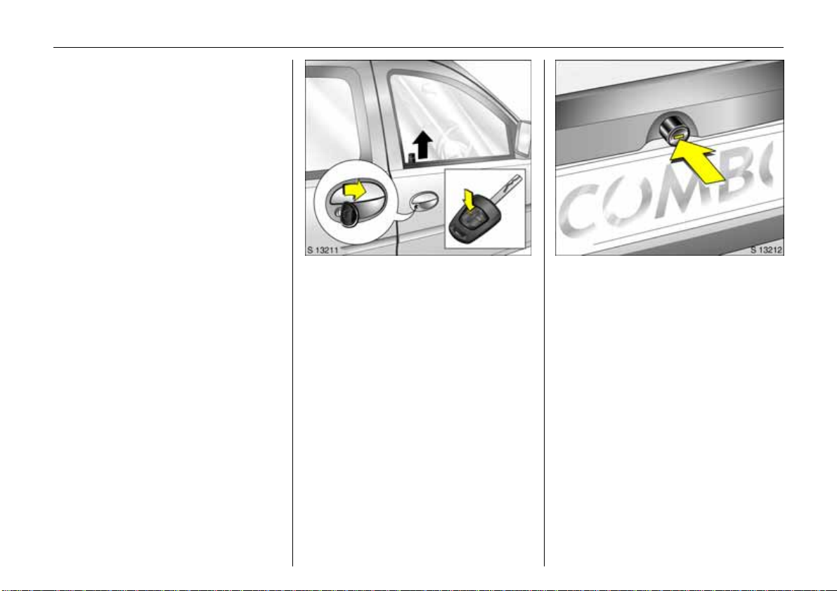
To unlock the vehicle and open
the doors:
With key in lock turn key towards
front of veh i cle or p r ess button
q
o n the r emote control 3,
pull door hand le and open doo r
or sliding door
Unlocking the door from inside:
P ull up on lock button.
6 Sliding do or 3 – see page 27,
door lock s, key – see page 18,
electronic immobiliser – see page 19,
ra dio remote control 3 – see page 21,
central locking system 3 – se e p age 24,
V aux hall alarm system 3 – see page 31,
child restraint system 3 – see page 27.
3
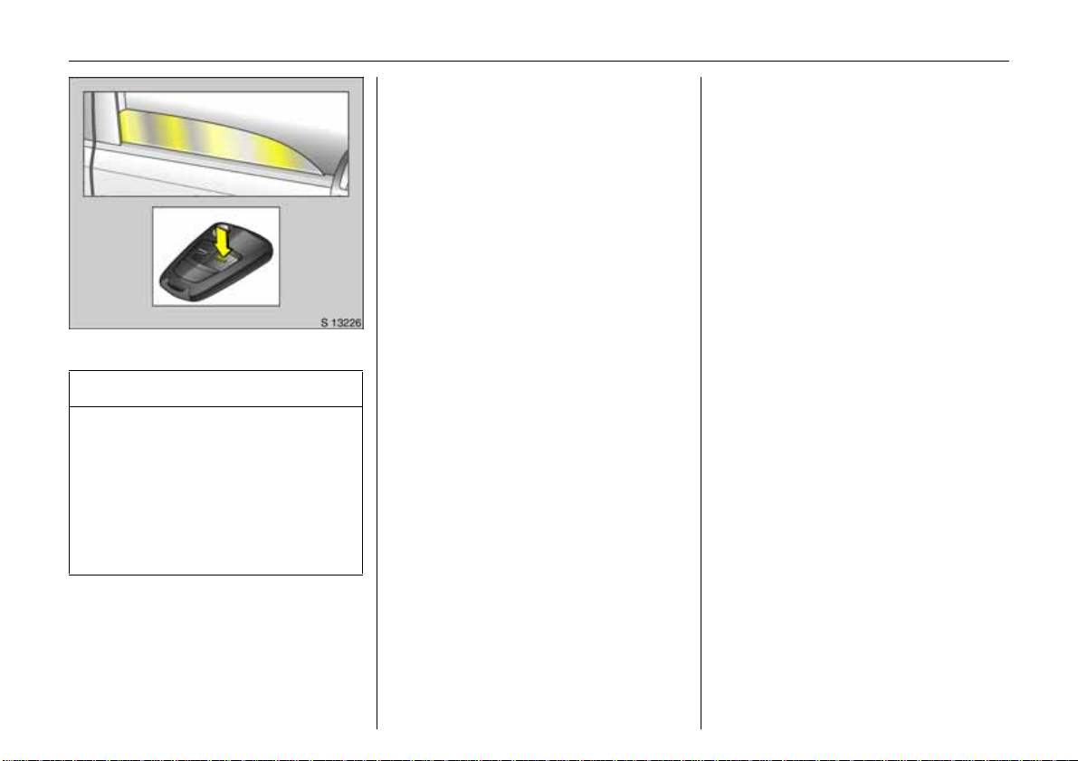
To unlock and open ta ilgate 3 :
Turn key to hor izontal position
orpress button
q on the radio
remote control 3,
pr ess button and open
tailgate u pwards
When using the remote control, the tailgate
is only unlocked if the key slot in the button
is in the horizontal position.
If the key slot is in the vertical position, the
tailgate is always locked.
6 Radio re mote control 3 – see page 21,
cen tral loc king system 3 – see page 24 ,
Vauxhall alarm system 3 – see page 31,
tailgate 3 – see page 28.
Page 8
3In Brief
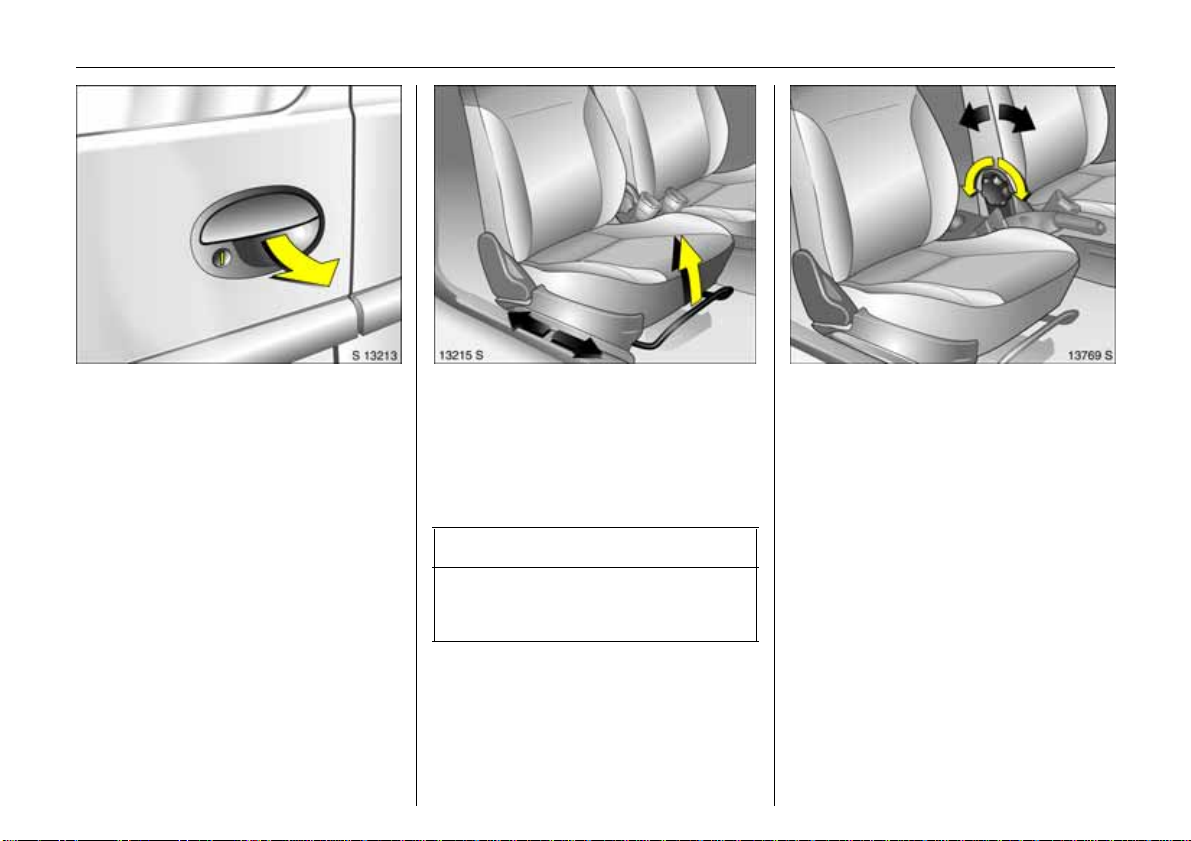
To un lock and o pen rear doors 3:
Turn key to vertical position or press
button
q o n the remoteco ntrol 3,
pu ll handle and open rear doo r;
to open the left rear door, swivel the
handle on the inside
Whe n us i ng the remote control, the rear
doors are only unloc ked if the key slot in the
lock is in the vertical position.
If the key slot is in the horizontal position,
the rear doors are always locked.
6 Radio re mote control 3 – see page 21,
central lock ing system 3 – see page 24,
Vauxhall alarm system 3 – see page 31,
rea r doors 3 – see page 29.
To adjust fr ont seats 3:
Pull handle, slide seat,
rel ea s e ha ndle,
allo w seat to audibly latch
into position
6 Seats – see page 38,
seat position – see page 3 9.
9 Wa r n i n g
Important: Do not sit near er than 10
inches (25 cm ) from the steering wheel, to
permit safe airbag deplo yment.
To adjust front seat backrests:
Turn handwheel
Mov e seat b ackre st t o s uit seati ng positi on.
Do not lean on seat backr est whilst
adjus ting it.
6 Seats – see page 38,
seat position – see page 39.
Page 9
4In Brief
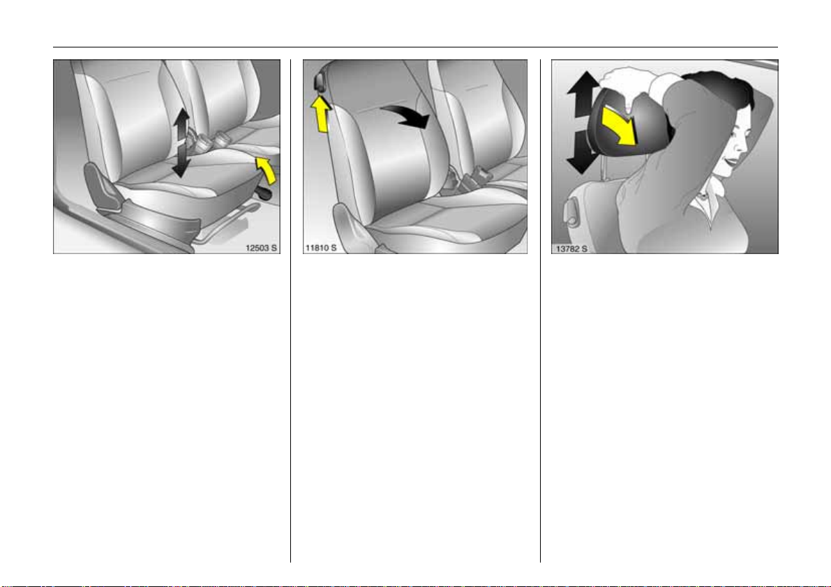
To adjust front seat height 3:
Pull le ver at side
Lift le v er an d relieve some weight from seat
to raise it or press down on seat with body
weight to low er it.
Never adjust the driver’s seat whils t driving.
It could move in an uncontroll ed manner
when the lever has been pulled.
6 Seats – see page 38,
seat position – see page 39.
To fold front seat backrest forward 3:
Raise release lever
To enter a nd leave the rear seat area, tilt
front seat back forwards.
6 Seats – see page 38,
seat position – see page 3 9.
Adjust head restra int he ight 3 of
fron t and rear o utboar d seats:
Tilt forward to re le ase ,
hold in place,
adj us t height and rel ease again
6 Head restrain ts – s ee page 40,
head restraint position – see page 40,
rear, cen tre head rest raint 3 – see page 40.
Page 10
5In Brief
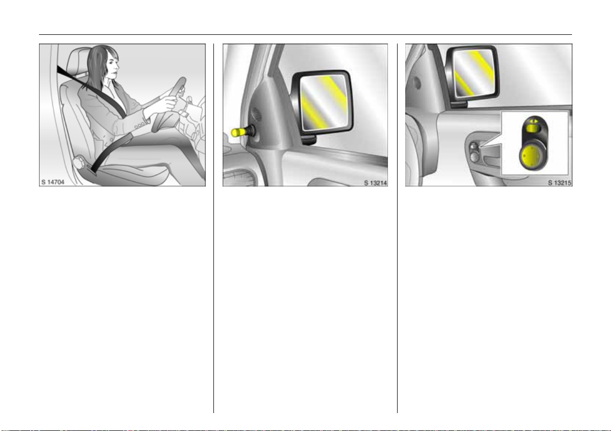
Apply seat bel t:
Pull out seat belt smoothly from
ine r tia reel, g uide over sh o ulder and
click into belt buckle
The seat be l t must not be twisted at any
point along its length. The lap belt must sit
c l os e to the bo dy . The ba c k r e s t mu st n o t be
tilte d bac k too fa r ( r ecom men ded
maximum tilting angle approx. 2 5°).
To release belt, press red button on belt
buckle .
6 T hree-point seat belt – see page 48,
airbag sy ste m 3 – see page 53,
seat position – see page 39.
Manually adjus table out side m irro r:
Swivel lever in the required direction
from the inside
6 Mirror – see page 34,
aspherical exterior mirror – see page 34,
fold in ou tside mirror – s ee page 34.
Ele c tr ic al ly adj us t a b le ex t erior
mirrors 3:
Four-way switch in driver’s door
Toggle switch to left or right: four-way
switch moves appropriate mirror.
6 Mirror – see page 34,
asph erical exterior mirror – see page 34,
folding in the exterior mirror – see page 34,
heated exterior mirrors – see page 34, 95.
Page 11
6In Brief
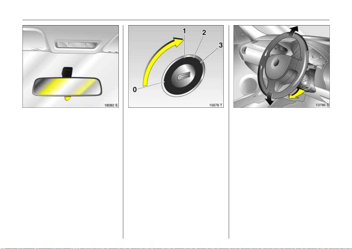
To adjust interior mirror:
Swivel mirror housing
Swivel lever on undersid e of mirror housing
to reduce dazzle a t night.
6 Mir ror – see page 35.
Steering column lock and ignition:
Tu rn key t o positi on 1,
move steering wheel slightly to
rel e a se loc k
Positions:
0 = Ignit ion off
1 = Steering free, ignition off
2 = Ignit ion on,
with di esel engine: pr eheat ing
3=Starting
6 Starting – see page 14,
electronic immobiliser – see page 19,
parking the vehicle – see page 15.
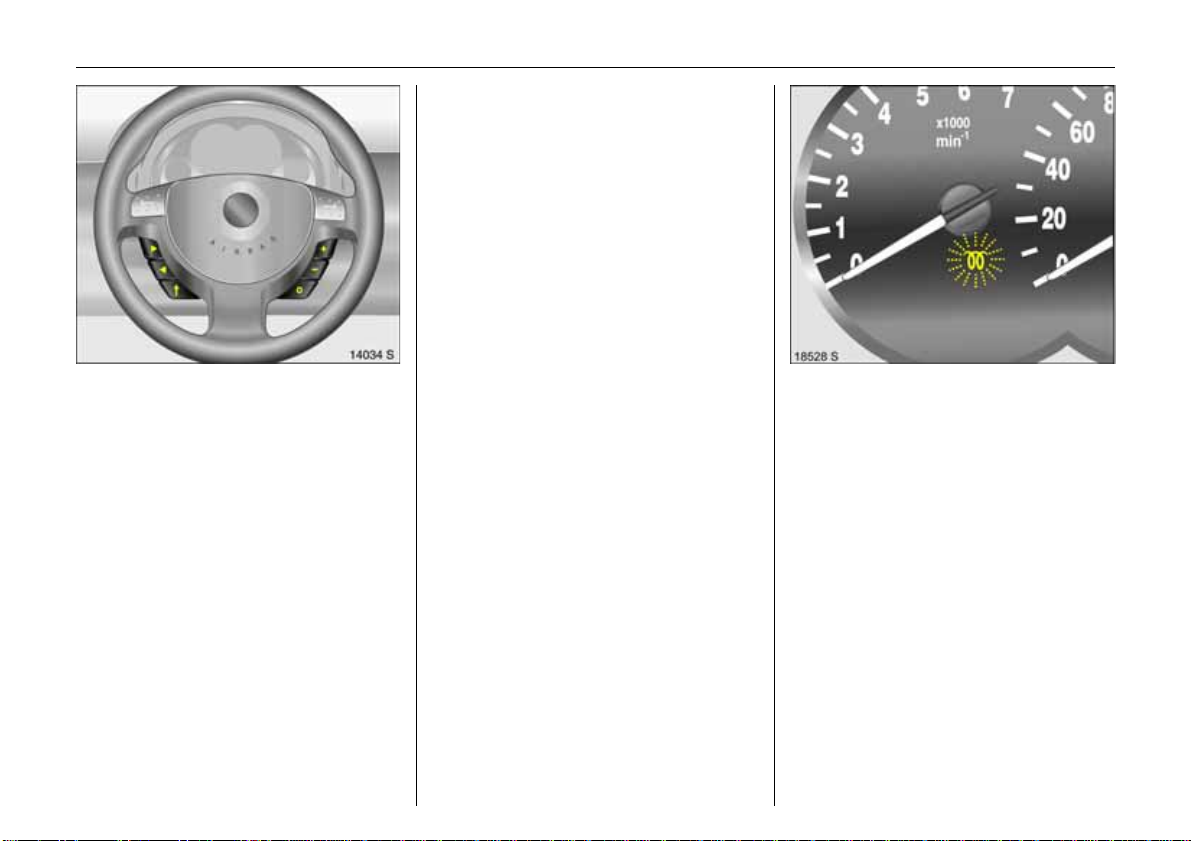
St eeri ng whee l ad just men t 3:
Sw ivel lever d own, adju st height ,
swivel l ever up, engage
Adjust st eering w heel on ly w hen vehicle is
station ary and steering column lock is
released.
6 Airbag systems 3 – see page 53.
Page 12
7In Brief
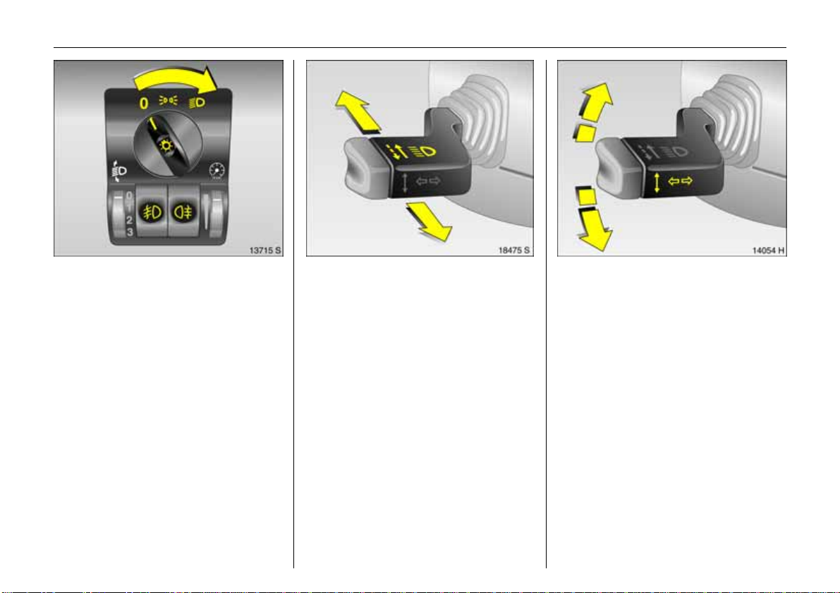
Turn light sw itch:
7 =Off
8
= Pa r k ing lig h ts
9 = Di pped or ma in beam
Press li ght swi tch:
0 =Courtesy light
Push button:
> =Fog lights 3
r
= Fog tail light
6 Lighting – see page85,
headligh t control indicator – see page 15.
Headlight flash, ma in beam and
dipped be am :
Headlight
flash
Pull s talk t o ward
=
steering wheel
Main beam = Push stalk
forward
Dipped beam = P ush stalk
forward again
6 Main beam, headlight flash –
see page 86.
Switch turn signal on:
Right = Move stal k upward
Left = Move stalk down ward
6 Turn signal – s ee page 86.
Page 13
8In Brief
Page 14

9In Brief
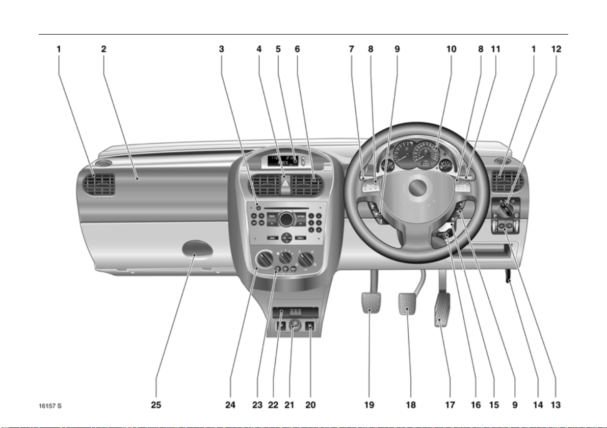
Page
1 Side air v ents ................................... 94
2 Front passenger airbag 3 .... ......... . 5 3
3 Infotainment system 3 ......... ......... . 91
4 Hazard warning lights .................... 11
LED for Vauxhall alar m syst em 3 ..32
5 Display 3 for time , date ,
outside temperature,
infotainment system 3 .............. ..... 77
6 Centre air vents ................................94
7 Turn signals, headlight flash,
dipped beam, main beam ......... 7, 85
8 Horn ............. ......... ......... ................... 11
9 Steering wheel remote control 3 .. ..91
10 In stru me n ts .. .... ..... .... ..... ........ ..... .... . 66
Pa ge
11 Windscreen wiper,
windscree n wash system,
rear wind ow wash system 3 .... ....... 8 3
12 Light switch .................................. 7, 85
13 Headligh t range adjustment 3 ...... 88
Fog tail light .................................... 87
Fog lights 3 ..................................... 87
Instrument illumination .. ................ 88
14 Bonnet release lever ...................... 132
15 Starter switch with steering
co lum n lock ..... .... ..... ........ ..... .... ..... ... 6
16 Steering wheel adjustm ent 3 ........ ... 6
17 Accelerator pedal ................. 109, 110
18 Brake peda l ........................... 110, 120
19 Clutch pedal 3 .... ......... ......... ........ 11 0
Page
20 Seat heating 3 ... ..... .... ..... ......... .... .. 95
21 Accessory socket or
cigarette lighter .............................. 62
22 Ashtray 3 ......................................... 63
23 Air conditioning system 3 ... ..... .... .. 99
Heated rear wi ndow 3 .............. 12, 95
Air recircul a ti on system 3............... 99
24 Heating and ventilation system .... 93
25 Glove compartment ....................... 64
Page 15

10 In Brief
Control indic ato rs
>
A
Z
v
Fog lights 3,
see pages 66, 87.
Engine elec tronics,
immobiliser 3,
Easytronic 3,
fault,
see pages 19, 66, 108.
Exhaust gases 3 ,
see pages 67, 116.
A irbag systems 3,
belt tensioners,
see pages 67, 50, 57.
I
O
C
!
T
r
Eng ine oil pressure,
see page 67.
Turn signal lights,
see pages 68, 86.
Main bea m,
see pages 68, 86.
Preheating 3,
die sel particle filter 3
see pages 68, 118.
Easytronic 3,
Winter progr amme,
see page 106.
Fog tail lig ht,
see pages 69, 87.
p
R
u
S
EPS
Y
Alternator,
see page 69.
Brake system,
clutch system 3,
see pages 69, 180.
Anti-lock Brake System 3,
see page 122.
Engine oil level 3,
see pages 70, 176.
Electric power steering 3,
see page 70.
Fue l level,
see pages 70, 114.
Page 16
11In Brief
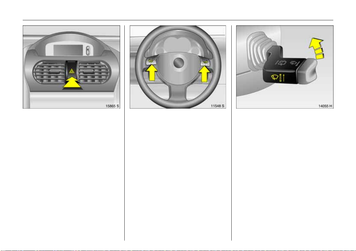
Hazard warnin g ligh t s:
On = Press ¨
Off = Press
6 Hazard warning lights – see page 87.
¨ again
Operate horn: press j right or left
6 Airb ag system 3 – see page 53,
remote con trol on steerin g
wheel 3 – see page 91.
Windscreen wiper:
move stalk upward
§ =Off
$ = Adjustable interval s witching
% =Slow
& =Fast
6 Windscreen wiper – see page 83,
adjustable wiper intervals 3 – see page 83,
additional notes – see pages 168, 180.
Page 17
12 In Brief
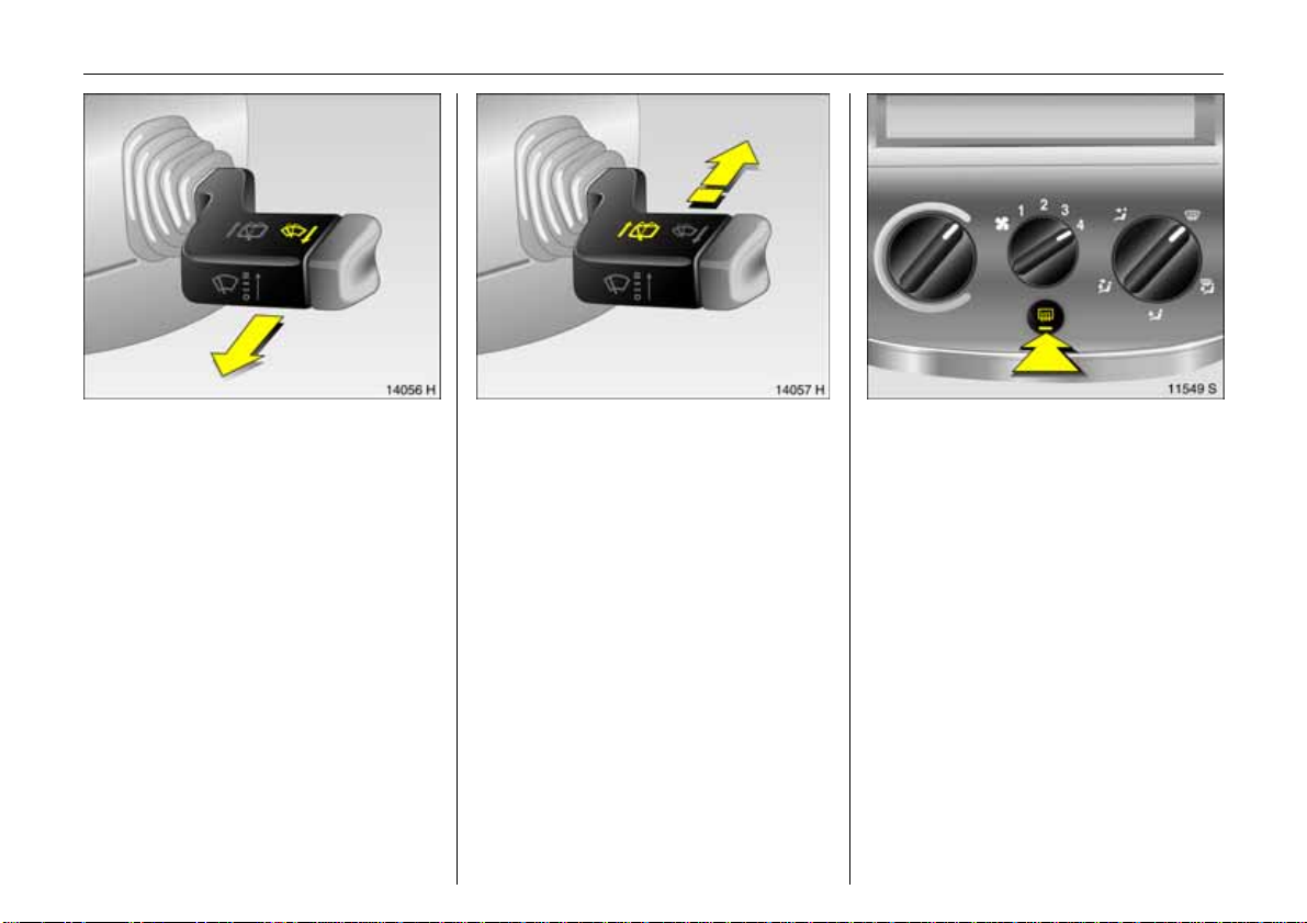
Oper a ting wind scre en wa sh syst em:
Pull stalk tow ard steering wheel
6 Winds creen wash system – see page 83,
additional n o tes – see pages 181, 197.
R ear window wiper 3 and
rear wind ow wa sh syst em 3
operation:
Wi p er on = Move s ta lk
forward
Wi p er off = P ul l s talk to w a rd
steering wheel
Wash = Push stalk
forward and h old
6 Rear window wiper and rear window
wash system – see page 83,
additiona l n otes – see pages 180, 181.
Heate d re ar window 3,
h ea ted ext e ri or mi rr or s 3:
On = Press Ü
Off = Press
6 Air conditioning – see page 93,
Heated rear window – see page 95.
Ü again
Page 18
13In Brief
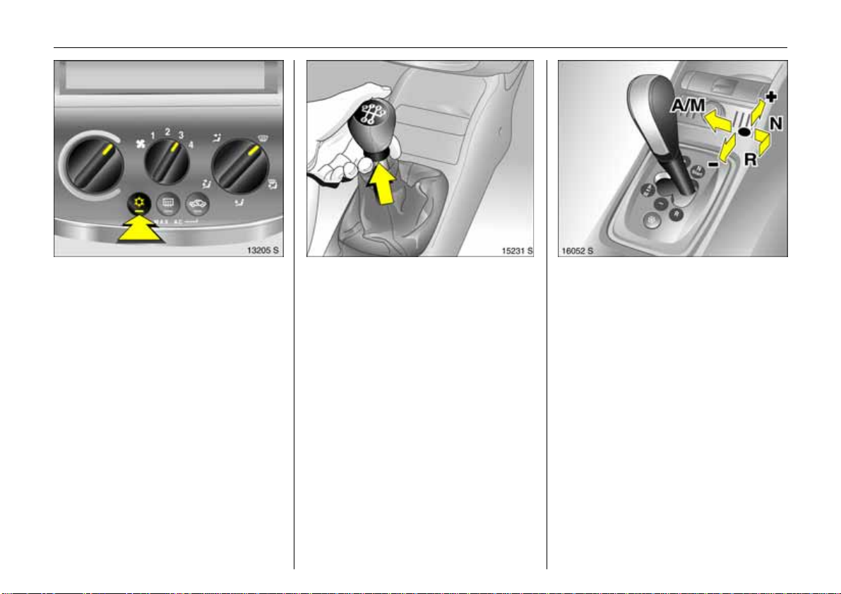
C learing misted or icy window s:
Turn rotary switches for temperature
a nd ai rf low c loc k w i s e,
set air distribution to
air conditioning system
V,
3:
also press switch n
6 A ir conditioning 3 – see page 93.
Manual transmission:
Reverse g ear: With vehicle stationary, three
seconds after d e-clut ching pullthe ring up
and engage gear.
If the gear do es not engage, set the lever in
ne utra l, release the clutc h pedal and
depress again; then repeat gear selection.
Easytronic 3:
N = Idle speed/start pos ition
o
=Drive position
(centre pos ition)
+ = Higher ge ar
- = Lowe r ge ar
A/M = Switch between Automatic
and Manual mode
R = Reverse gear (with selector
lever lock)
To move the selector lever from N to R
press the button on the lever.
Only sta rt in N with footbrake applied.
6 Easytronic 3 – see page 103.
Page 19
14 In Brief
Be fore s t arting off, check:
z Tyre pres sure and tyre condition -
see pages 123, 193.
z Engine oil level and fluid levels in engine
co mpartment – see pages 176 to 181.
z All windows, mirrors, exterior lighting
and number plates are free from dirt,
snow and ice and operational.
z Do not place any objects in front of the
rear window, on the instrument p anel or
in the area in which the airbags inflate.
z Seats, seat bel ts an d mirrors are
co rrectly adj usted.
z Check brakes.
T o start the engine:
D epres s clutch and brak e ped als ,
Eas ytronic
3 in N,
do not acce lerate,
petrol engine : key to 3 ;
diesel engine: key t o 2 ,
whe n control indicator
! goes out
1)
key to 3;
rele as e k ey once engine is running
T o repeat the start procedure or switch off
th e engine, turn the key back to 0.
To switch on the ignition, turn the key to 2.
6 Electronic immobiliser – see page 19,
diesel fu e l sy stem – see page 132 .
To release the handbrake:
Raise le ver slightly,
pr ess lock but ton,
lower lever fully
6 Handbrake – see pages 69, 121.
,
1)
Preheating system switches on only if ou tside
temperature is lo w.
Page 20

15In Brief
Par k ing th e vehic le
z A pply handbr ake fi rmly without press ing
the release button. On slopes apply the
h andbrake as firmly as pos sible.
z Switch engine off by turning ignition key
to 0. Remove ignition key and turn
steering wheel until lock is felt to engage
(anti-theft protection).
z f the vehicle is parked on a level surface
o r an u phill slope, with a manual
gearbox s elect first gear or with
Easytronic 3 move the selector lever to
the centre position before switching off
the ignition. Also turn front whe els away
from kerb if vehicle is on an uphill slope.
If th e vehicle is on a downhill slope, with
manual gearbox o r Easytron ic 3 se l ec t
reverse gear before switching off the
ignition. Also turn front wheels toward
kerb.
z Lock doors and load compartment and
activate V aux hall alarm system 3, by
turnin g the key in lock or pre ssing
button p on remote control. To also
activate the anti-theft locking system 3
press bu tton p twice.
Ad v i ce w hen p a r k i ng :
z Do not park vehicle on e asil y ignit able
surfaces as the hot exhau st system
temperatures could c ause the surfa ce to
ignite.
z On vehicles with Ea sytronic 3 the contro l
indicator R flashes for a few seconds
after the ignition is switched off if the
handbra ke has not been a ppl ied.
z Close windows.
z The engine cooling fans m ay ru n after
the engine has been switched off –
see page 175.
6 Additional notes – see page 109 ,
door locking – see page 20,
ra dio remote control 3 – see page 21,
central locking system 3 – se e p age 24,
V aux hall alarm system 3 – see page 31,
vehicle deco mmissioning – see page 183.
That was a brief o verview of the most
imp ortant information for your first
trip in your vehicle.
The oth er pages of t his chapter
contain a description of some
interes tin g funct ions in your vehicle.
Th e remaining c hapters of the
Owner’s Manual contain important
i nfo rm at io n on o pe ra t io n,
s afety and mai nte nance as
well as a complete index.
Page 21
16 In Brief
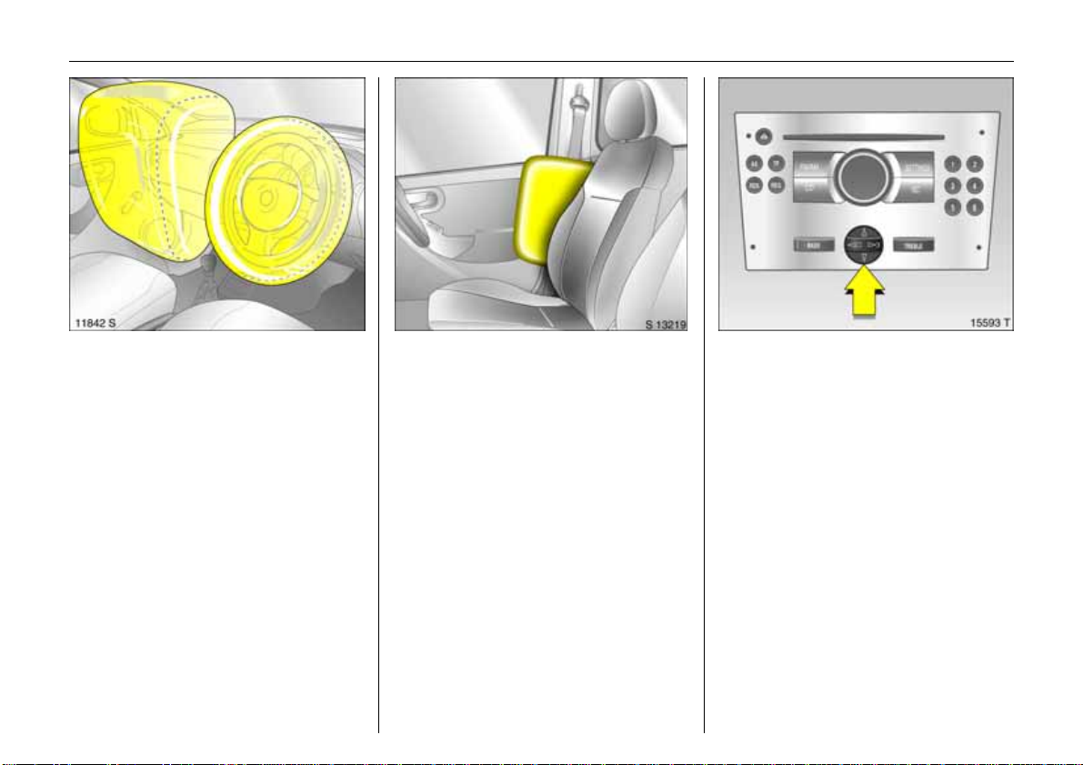
Vauxhall Full Siz e ai rbag system
The Vauxhall Full Size airbag system
consists of se veral inte rna l systems .
Front airbag system 3
The front airbag system will be triggered in
the event of a serious accident involving a
frontal impact and f orms safety cushions
for the driver and front passenger. The
forward movement of the driver and front
passenger is checked and the risk of
injuries to the uppe r body and head
thereby substantially reduced.
Side airbag system 3
The side airbag sy stem t rigg er s when
a side-on collision occurs and provides
a safety barrier for the d river and/or
passenger in the respective front door
area. Th i s reduces the risk of injury to the
u pper body considerably in case of a
side-impact.
6 Airbag system – see page 53.
Operating via the i nfo rmation
di spl ay m en us
The menu options a re selected via the
men us and with the button/four-wa y
button or the multi-function button of the
infot ainment system 3 or via the buttons 3
on the steering w heel. The menu options
appear on the displa y.
To sel ect with four-way button:
Press four-way button up , down, right or
left.
Page 22
To sel ect with the multi-fun cti on button
(rotary knob abo ve the four-way button -
see page 78):
Press and turn multi-fun ction button.
To exit a menu, turn the multi-fun ction
button left or right to Re turn or Main and
select.
To se lect with s teering wheel buttons 3:
Select menu options via t he menus using
the buttons.
6 Information Display – see page 77.
Diesel particle filter 3
The diesel p artic le filter sys tem remo ves
poll uting soot particles out of the engin e
exhaust gases. The system includes a selfcleaning function that opera te s
automatically while driving. The filter is
cleaned by burning the trapped soot
particles at a high temperature. There may
be an increase in fuel consumption,
exhaust sm ell, and engine cooling fan
op eration 3 during the self-cleaning
op eration.
T he self-cleaning fu nction can not operate
automatically during certain driving
sit uations wh ere the engine does not r each
its normal operating temperature. An
example of this would be driving only short
di st an c e s in col d wea th e r .
17In Brief
If the fi lter needs clean ing and recent
driving situations did not allow the function
to operate automatica ll y, then the control
indicator ! will flash. If this occurs, then
you may cont inue to d r iv e the vehicle
normally. The vehicle will not be damaged
and does not require service.
The self-cleaning function will operate
automat ically while driving after the
engine has reached its normal operating
temperature. The c ontrol indicator ! will
continue to flash until the self-cleaning
operation is complete. This may t ake up to
20 minutes of driving. T he tim e w ill be
shorter at higher vehicle speeds .
6 Diesel particle filter – see page 118.
Page 23
18 Keys, Doors, Windows
Keys, Doors,
Windows
Replacement keys ............................... 18
Ca r Pass ... .... .... ..... ......... .... ..... .... .... ...... 1 8
Key with re tractable key blade 3 ...... 18
Electronic immobiliser.......................... 19
Me chanical unlocking or lo ck ing of
individual doors................................. 20
Radio remote control 3....................... 21
Central locking syst em 3.................... 24
Sliding doors 3..................................... 27
Tailgate 3 ............................................ 28
Rear doors 3........................................ 29
Vauxhall alarm system 3.................... 31
Exterior mirrors..................................... 34
Interior mirror....................................... 35
Manual window opera tion, front
doors .................................................. 35
Windo w in th e sliding doors 3............ 35
Electric windows 3 ............................... 36
Replacement keys
The key number is specified in the vehicle
documents and in the Car Pass 3.
The key is a constituent of the electronic
immobiliser. Orderi ng keys from a Vauxhall
A uthorised Repairer guarantees problemfree operation of the electronic
immobiliser.
Keep the spare key in a safe place.
Locks, see pages 20, 170.
C ar Pass
The Car Pass c o nt ains all of th e vehicl e’s
data and should therefore not be kept in
th e vehicle.
Have yo ur Car Pass at hand when
consulting a Vauxhall Authorised Repairer.
Pic tur e no: 15760t.t if
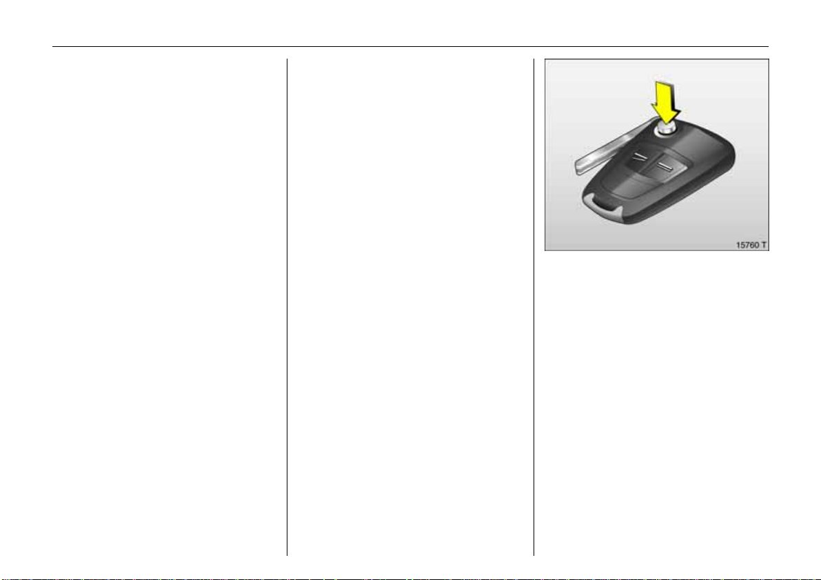
Key with retractable key blade 3
Press button to ex tend. To retract, press
button and audibly engage key blade.
Page 24
19Keys, Doors, Windows
If control i ndicator A illuminates after the
engine has s ta rted, ther e is a fault in the
engine electronics or the Easytronic
transmission, see page 108.
Note
The immobiliser does not lock the doors.
Therefore, after leaving the vehicle always
lock it and swit ch on th e Vauxhall alarm
system 3, see pages 20, 24, 31.
Pict ure no : 15761t.t if
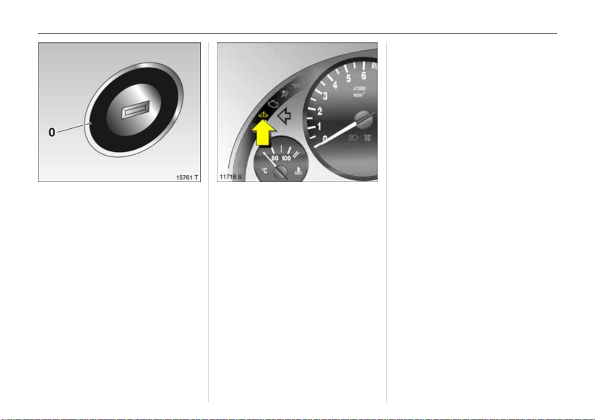
Electronic immo biliser
The s yst em c hec ks whet h er t he vehic l e may
be started using the key that has been
inserted. If the k ey is "authorised", the
vehicle can be started. This check is carried
out via a transponder h oused in the key.
The electronic immobiliser activate s
automatically whe n the key is removed
from the starter switch.
The c ode number of the electronic
immobiliser is given in the Car Pass .
Control indicator for immo biliser A
Pic tur e no: 11718s.tif
Con trol ind ica tor A illuminates briefly
after the ignition is switched on.
If the control indicator flashes when the
ign ition is on, there is a fault in the system;
the en gine cannot be started. Switch off
th e ignition an d then repeat the s tart
attempt.
If the control indicator A continues to
flash, please try to start the engine using
the second key and contact a workshop.
Page 25
20 Keys, Doors, Windows
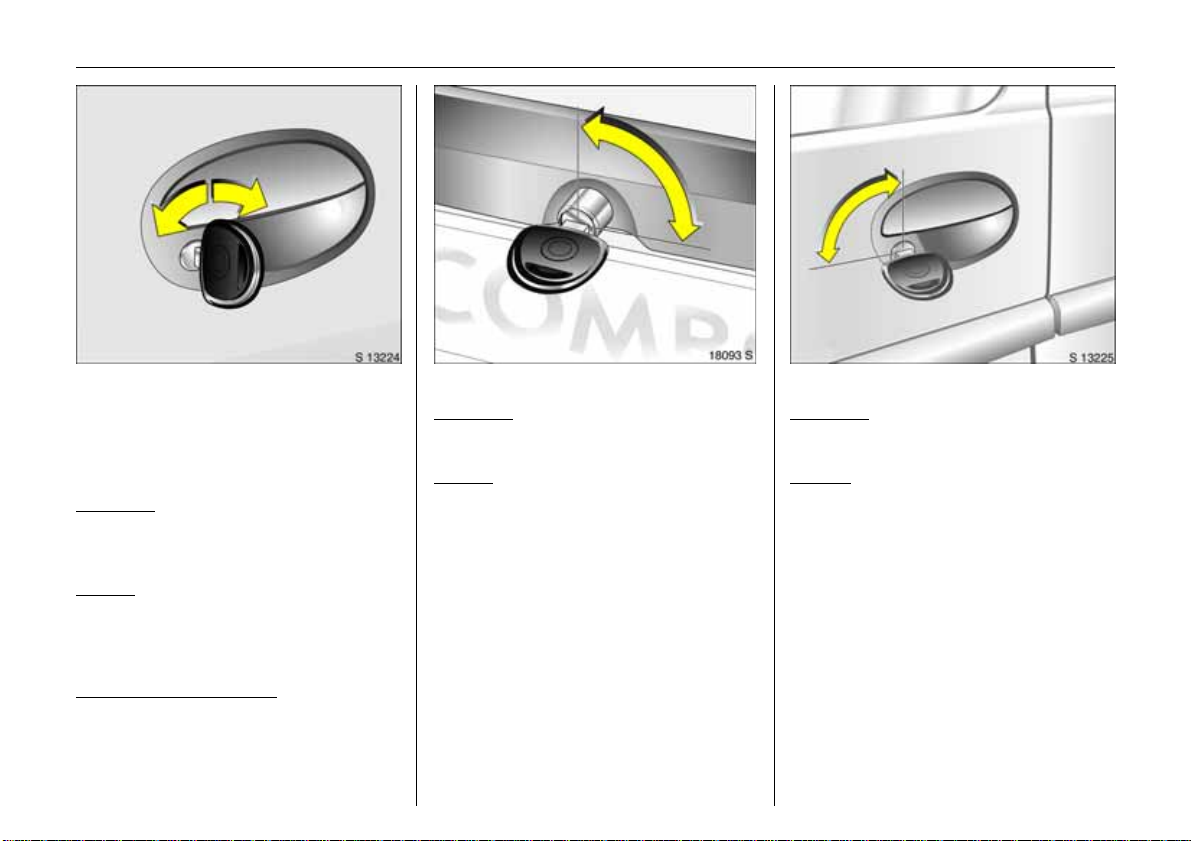
Pict ure no: 18115s.tif
Me chanical unlocking or lo cking
of individual doors
(versions without remote control 3 and
central lock ing system 3)
Front doors and sliding doors 3
To unlock
Turn key in lock towards front of vehicle as
far as it will go. Return key to the vertical
position and remove. Pull door handle .
To lock
With door or sliding door clo sed, turn key
towards rear o f vehicle as far as it will go.
Tur n key back to vertical position and
remove.
Operating from the inside
Pull or press the interior lock b utton.
Tailgate 3
Pic tur e no: 18093s.tif
To un l o c k
T urn key in lock to horizontal position and
remove. Press button.
To l oc k
With tailg a te closed, turn key in lock to
vertical position and remove.
Rear door 3
Picture no: 18095 s.tif
To unlock
Turn key in lock to vertical position and
re move. Pull door ha ndle.
To lock
Close first left and then right rear door.
Turn key in lock to horizontal position and
remove.
Page 26
21Keys, Doors, Windows
Central locking system,
see page 24.
Mechanical anti-theft locking s ystem 3,
see page 24.
Vauxhall alarm system 3,
see page 31.
Electric windows 3,
see page 36.
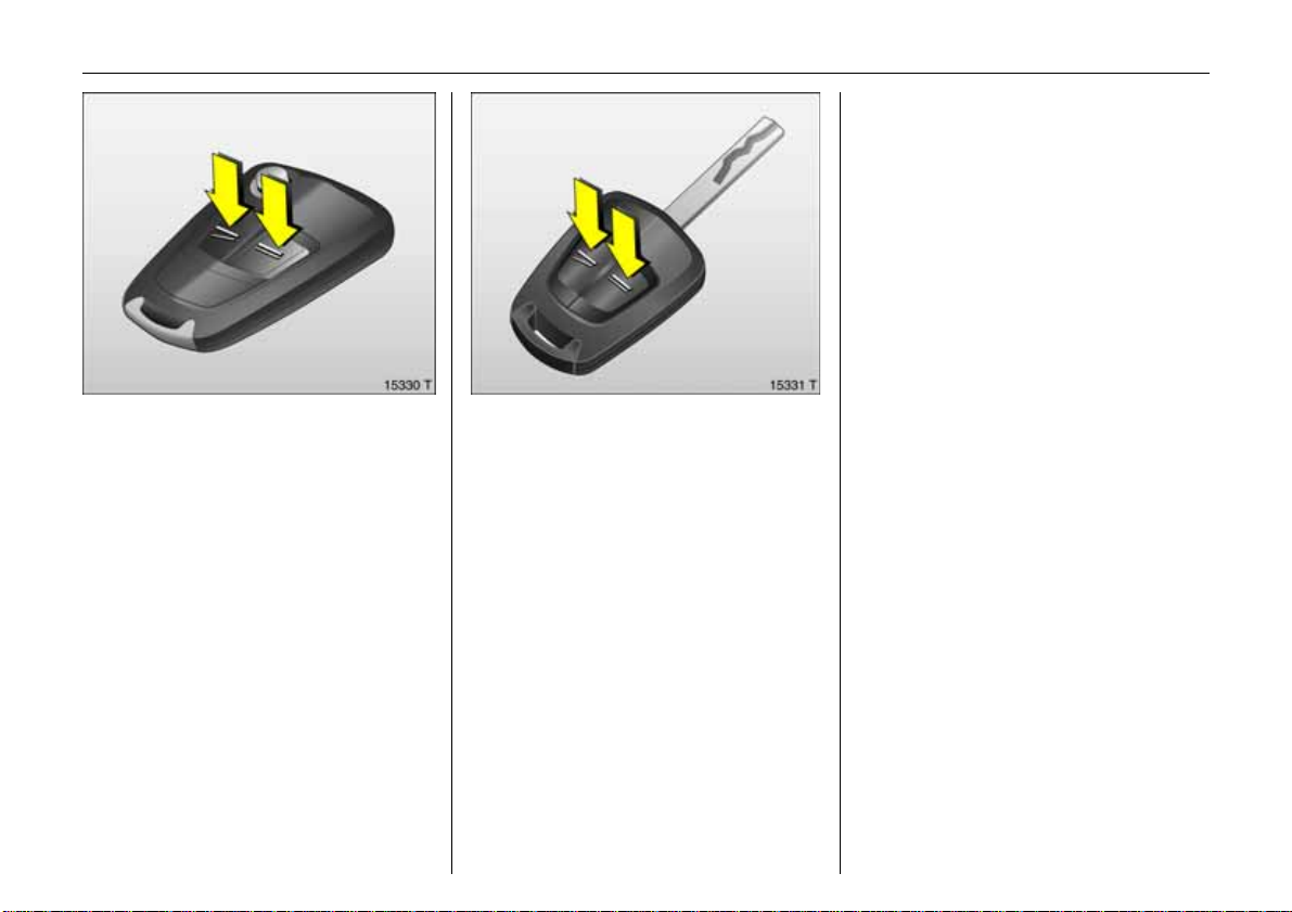
Pict ure no : 15330t.t if
Ra di o remo te con tr ol 3
Depending on the equip ment of the
v ehicle, one of the remote controls
depicted on this page will be used.
The radio remote control is integrated in
the key.
Us ed to op er at e :
z central locking system 3,
z mechanical anti-theft locking system 3,
z Va uxhall alar m system 3,
z and closing of the front door window s on
vehicles with electric windows 3.
The remote control has a range of approx.
5 m etres. Thi s range can be affected by
outside influences. Aim the remote control
at the vehicl e to op erate.
Handle the radio remote control with care,
Pict ure no: 15331t.tif
protect it from mo isture and high
temperatures and avoid unnecessary
op eration.
The hazard warning lights come on to
indicate that the remote control is
operational.
Page 27
22 Keys, Doors, Windows
Fault
If the central locking system cannot be
operated wit h the radio remote control,
it may be due to the follo wing:
z The range of the radio remote control
has been exceed ed.
z Radio remote control battery voltage is
too low. Battery replac ement –
see Fig. 15332 T.
z F req u ent , r epe a ted op er at io n of the
radio remote control outside the
reception range of the vehicle (e.g . too
far from v ehicle, remote control is then
no long er recogni sed). R emo te cont r o l
synch ronis ation - see next page.
z If the central locking system is
ove rloa ded as a r esult of repeated
operation at short intervals. The power
supply is cut off for a brief period.
z Interference from higher-power radio
waves f rom other sour ces.
W e reco mmend t hat you contact a
workshop in order to have the cause of the
fa ult re medied.
Manua l unlocking o r lock ing with the
v ehicle k ey - see pa ge 26.
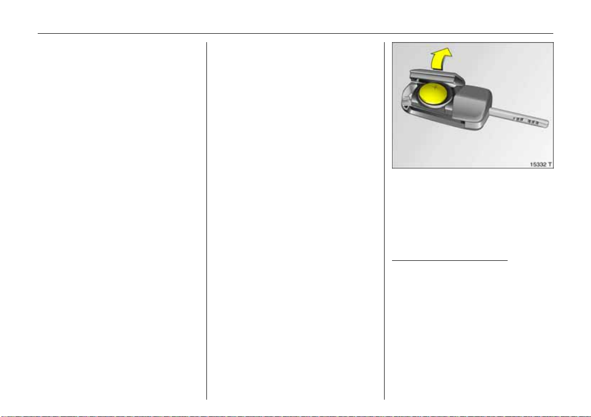
Re mot e cont rol bat ter y repla cement
Pic tur e no: 15332t.t if
Replace the battery as soon as the range
of the radio remote contr ol begins to
shrink.
Make sure that you dispose of old ba t te r ie s
in accordance with environmental
protect ion regulations.
Key with retractable key blade
See Fig. 15330 T o n previous page.
Extending key blade - see page 18.
Open remote control. Replace battery.
Battery type - see page 196. Note
installation position. Close remote control.
Page 28

23Keys, Doors, Windows
Key with fixed key section
See Fig. 15331 T - see page 21.
Hav e th e battery changed in a wor kshop.
Synchronise the remote control in the
e ve nt of func tiona lit y problems or batter y
rep lacement
A fter changing the battery, unlock door
with key in lock, see page 26. Inserting th e
key in the ignition synchronises the radio
re m o t e c o nt r ol .
Page 29
24 Keys, Doors, Windows
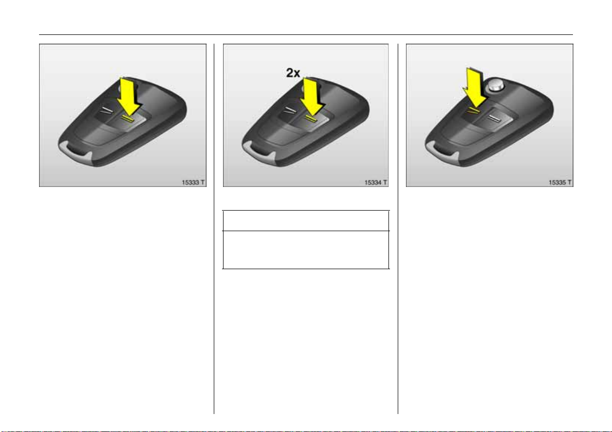
Pict ure no : 15335t.t if
Cen tra l locking s ystem 3
for doors, sliding doors 3, l oad
compartment and tank flap 3.
To lock
Press button p on th e radio remote control
– or from the in side –
push the lock button on the driver’s door
when the doors are closed.
Mechanical anti-th eft locking system 3
Pict ure no: 15333t.tif
9 Wa r n i n g
Do not use the system if there are people
in the vehicle! The doors cannot be
unl oc ked fro m inside .
All doors must be closed. No m ore than
10 seconds after unlocking, press button p
o n the radio remote control again
L ock buttons on all doors are posi t ioned
such that doors cannot be opened.
If t he igniti on w as on, the dr iver’ s d oor
must be opene d and closed once so that
the vehicle can be secu red.
To unlock
Pic tur e no: 15334t.t if
Pre ss bu tton q on the radio remote cont rol
– or from the inside –
pull lock button on driver’s door.
Wh en the mechan ical anti-theft lock ing
system 3 is enab led, the doors cannot be
unlocked by pulling up the lock buttons.
Country-specific version 3: Pressing the
button once will unlock the driver ’s door.
Pressing the button twice will un lock the
entire vehicl e.
Page 30
25Keys, Doors, Windows
Closing windows 3 from outside
Pict ure no: 17899s.tif
9 War n ing
Exer cise care when operatin g electric
wind ows. Risk of injury, especially for
children.
Vehi cl e passengers should be infor med
according ly.
Keep a close watch on the windows when
closing them. Ensure that nothin g
becomes trapped in them as they move.
On vehicles with electric windows , the front
door windows can be closed from out side
the vehicle:
Hold bu tton p on the remote control
depressed until the window s are
comple tely closed.
Note
z To prevent the driver from being
inadvertently lock ed out, the button on
the driver’s door cannot be depressed
when t he door is open.
z If the dr iver’s doo r is not closed properl y,
the central locking system will unlock
again immediat ely after locking.
z 30 seconds after unlocking using the
radio remote control the doors lock
again automatically if no door is
opened.
z To lock the doors from inside (e.g . to
prevent unwanted entry from outside),
push down lock button on driver’s door.
z Locked doors unlock automatically if an
accident of a certain severity occurs (to
permit outside assistance). –
Prerequisite: Ignition must not be
switche d off.
z If a sliding do or 3 is op en when the
vehicle is being locked, it is locked a few
seco n ds a fter it has b een closed.
Fault
If the central locking sy stem cannot be
operated, the problem may be as follows:
z If the central locking system is
overloaded as a result of repeated
operation at short intervals. The power
supply is cut off for a brief period.
z Defective fuse i n fusebox – see
page 153.
Please contact a workshop to have the
ca use of the fault remedied.
Opera te dr iver d oor w ith key, see next
page.
Page 31

26 Keys, Doors, Windows
Manual unlocking or locking with the
Pict ure no: 17881s.tif
vehicle key in the event of remote control
malfunction
To unlock
Turn key in driver ’s door lock towards front
of vehicle, turn back to vertical position
and remov e. The entire vehicle is unlocked.
Switch on ignition to deactivate Vaux hall
alarm syste m 3.
To lock
With the driver’s d oor clo sed, tur n key i n
lock towards rear of veh i c l e, turn back to
vertical position and remove. The entire
vehicle is locked.
Manual unlocking or locking with the
vehicle key in the event of central locking
system malfunction
To un l o c k
T urn key in driver’s door lock towards front
of vehicle, turn back to vertical p osition
and remove. The driver’ s door is u nlocked.
T he other doors can be opened by pulling
th e lock button (unless the anti-theft
lo cking system 3 is active). Switch on the
ignition to deactiv ate the Vauxhall alarm
system 3.
To l oc k
With the driver’s door open, press the lock
button of one of the other door s. Cl ose the
driver’s door and turn the key in the driver’s
doo r lock toward the rear of the vehicle,
tu rn it back to the ve rti c a l position and
remove. The unlocked fuel filler flap 3
cannot be locked.
Note
z The mechanical anti-theft locking
system 3 and the Vauxhall alarm
system 3 cann ot be activated with
the key.
z To deactivate the Vauxhall alarm
system 3 alarm, switch on the ignition
after open ing a door.
z Have cause of fault re medied by a
workshop.
Page 32

27Keys, Doors, Windows
Pict ure no: 18098s.tif
Sliding doors 3
9 War n ing
If th e vehicle is parked facing down a
slope, ope n sliding doors may mov e
accidentally on account of their weight.
Before driv ing off, check that the slid ing
doors are properly closed.
Opening from outside
To unlock the door, turn the key i n the l ock
towards the front of the vehicle or pre ss
button q on the remote control.
To open th e slid ing doors, pull the handle
and slide the door towards the rear of the
vehicle.
Opening from ins ide
Pic tur e no: 18092s.tif
T o open the unlocked slidin g door, pivot
the handle and slide the door towards the
rear of th e vehicle.
T o prevent damage, the right-hand s liding
door cannot be fully opened if the tank flap
is open.
To cl o s e
Slide the slidin g door until it engages.
To lo c k the door, turn the ke y in the lock
towards the rear of the vehicle, p ress
button p on the remote co ntrol or press
th e interior lock b utton.
Child safety locks 3
Picture no: 18091 s.tif
9 Wa r n ing
Use the child safety lock whenever
children are occupying the r ear seats.
Disregard may lead to inju ries or
e ndanger life. Vehicle pa ssengers shoul d
be informed accordingly.
With the sliding door open, use the k ey to
turn the rotary kno b at the doo r l ock from
the ve r t ical positi on: the cl osed door
cannot be opened fr om the inside.
Page 33

28 Keys, Doors, Windows
Pict ure no: 18116s.tif
Tailgate 3
To open:
Turn key in lock to vertical position or press
button q on the remote control.
Press the button to open the tailgate.
To close:
Close the tailgate and turn th e key in the
lock to a ho rizontal positio n or press
button p on the remote control.
Central locking 3 and the tailgate
Pic tur e no: 18118s.tif
T he central locking system and anti-theft
lo cking system 3 for the doors cannot b e
o perated via the tailgate lock.
Key slot horizontal in lock
When the central locking s ystem is
o pe ra ted , t he t ai lg at e is l oc ked or unl ock ed
togethe r with the doors.
If the k ey is turned to the vertical position
aft er unlockin g via the central locking
system, the tailgate re mains locked.
K e y s l o t v e r t ic a l in lo c k
The tai lgate r emains l ock ed when the
doors are locked or un lo cked via the
central locking system. C hoo se this position
if the tailgate is to always remain locked.
Unlockin g the tailgate with the ke y w ith
Picture no: 18094 s.tif
ce ntrally locked d oors 3
Turn the key clockwise as far as poss ible
beyon d the resistance point from the
vertical or horizontal pos ition. To
safeguard against being locked out, the
key cannot be removed when in this
pos ition.
Relock the tailgate by closing it and turning
the key to the horizontal or verti c al
pos ition.
In the horizontal position, the tailgate will
be unlocked the next time the vehi cle i s
unlocked via the central locking system.
Page 34

29Keys, Doors, Windows
Pict ure no: 18117s.tif
Rear do or s 3
To open:
Turn key in lock to vertical position or press
button q on the remote control.
Open right-hand rear door from outs ide by
raising door handle or from inside by
pivoting handl e.
Unlock and open the left-hand rear door
Pic tur e no: 18096s.tif
from inside by pivoting the handle.
T he doors engage at a 90° position.
Both door s c an be open ed up t o 180°:
Close the door s lightly from the 90 °
position, disengage the stop lug from t he
gui de rail and open the door completely.
When the doors are open 180°, the rear
Picture no: 14653 s.tif
exterior lighting is covered. Therefore, only
open the doors until they engag e when it is
dark outside.
When closing, make sure that the stop lug
properly engages in the guide rail.
To close:
Push first the left and then the right rear
door past slight res istance. Tu rn the key in
the lock to the horizontal position and
remove or press button p on the remote
cont rol.
Page 35

30 Keys, Doors, Windows
Pict ure no: 18119s.tif
Central locking 3 and the rear doors
The central locking system and anti-t heft
locking system 3 for the doors cannot be
operat ed via the rear door loc k.
Key slot vertical in lock
When the central locking system is
operated , the rear doors ar e locked or
unlocked together with the sid e doors.
If the key is turned to the vertical position
after unlocking via the central locking
system, the rear doo rs rem ain locked .
Ke y slo t ho r izo ntal in lock
The rea r d oors remain l ocked when the side
doors are locked or unlocked via t he
central locking system. Choose this position
if the rear doors are to always remain
locke d.
Unlocking the rear doors with the key wi th
Pic tur e no: 18120s.tif
centrally locked side doors 3
T urn the key anti-clockwise as far as
possible bey ond the resistance point from
the vertical or horizontal position and pull
the handle of the rear door. To s afeguard
against being locked out, the key cannot
be removed when in this position.
Relock the rear doors by closing them and
tu rning the key to t he horizontal or vertica l
position.
In the vertical position, the rear doors will
be unlock ed the next time the vehicl e i s
u nlocked via the central locking system.
N ot e s on tail gat e or re ar doors
z Fitting of accessories on the tailgate will
in crease its weight. If it becomes too
h eavy, it will then not stay open.
z The n um ber plate ca n o nly be seen when
the tailgate or rear doors are closed. Do
not drive with a n open tailgate or open
rear d oor s.
9 Wa r n ing
Do not drive with load compartmen t
ope n when trans porting b ulky objects , for
e xample , since to xic exhaus t fume s could
penetrate the in terior.
Page 36

Va uxhall alarm system 3
monito rs
z t he doors, load compartment, bonnet
z the pass enger compartment
z vehicle tilt, e.g. if it is raised
z the ignition.
9 War n ing
Do not activate the system if there are
people in the vehicle ! The doors ca nnot
be unlocked from inside.
31Keys, Doors, Windows
To activ ate
Pict ure no: 15334t.tif
All doors, wind ow s an d the bonnet must be
closed. Press butto n p on the remote
con trol to lock all doors and activa te the
V aux hall alarm system.
.
If t he igniti on w as on, the dr iver’ s d oor
must be opene d and closed in order to
activate the Vauxhall alarm system.
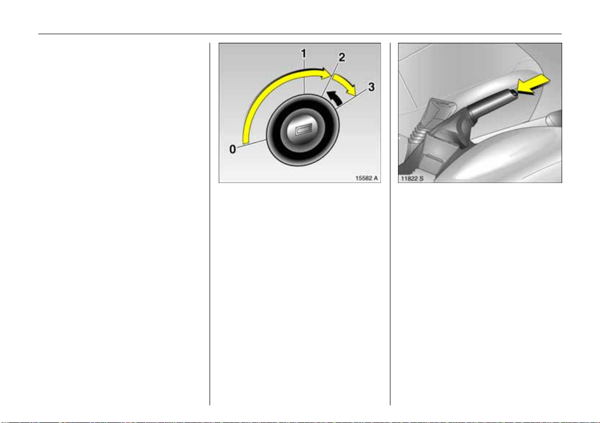
Activation witho ut monito ring of
Picture no: 11575 s.tif
passenger compartment and vehicle tilt
Switch on if, for example, you wish to leave
animals in the vehicle.
1.C lose l oa d com partm ent and b onnet.
2. Press button i n front of the courtesy light
(wit h ignition off); LED in the h azard
warning light button flashes a maximum
of 10 seconds.
3.Cl ose doors.
4. Switch on Vauxhall alarm system.
LED illuminates. After approx.
10 seconds, the system is activated
without monitoring of the passenger
compartment or vehicle tilt. The LED
flashes until the system is switched off.
Page 37

32 Keys, Doors, Windows
After the first 10 seconds of Vauxhall alarm
system activation:
z LED flashes
slow ly
z LED illuminates
for approx.
1second
If a system error occurs, ple ase con tact
aworkshop.
=System switched on,
= Switch-off function.
Light emitting diode (LED)
Pict ure no: 15987s.tif
During the first 10 seconds of Vauxhall
alarm syste m activation :
z LED illuminates
z LED flashes
ra pidly
= Test, delayed
switch-on,
=Door, load
compartme nt or
bonnet o pen, system
error.
To deactivate
Pic tur e no: 15335t.t if
Press butt on q on remote control
– or –
switch on ignition.
If there is a fault in radio remote control,
turn key in driver’s door lock toward front
of vehi cle as far as it will go. Then turn ke y
back to vertical position and remove.
If the alarm is triggered when the driver’ s
door is ope ned, deactivate the Va uxhall
alarm sy stem by sw itching on the ignition.
Page 38

Opening and closing the load
Pict ure no: 18094s.tif
compartment 3 when the Vauxhall alarm
system is enabled
1. To unlock:
Ta ilgate: T urn key clockwise all the way
past the horizontal pos i tion. The ta i lg at e
is unlocked and monitor ing of the
passenger compartment and vehicle tilt
are disabled.
Rear doors: Turn key anti-clockwise all
Pic tur e no: 18120s.tif
the way past the vertical position. The
rear doors are unlocked an d monitori ng
of the passenger compartment and
vehicle tilt are disabled.
2.Open the tailgate o r rear doors.
3.Close the tailgate or rear doo rs.
4. To lock: Turn key back to horizontal or
vertical position. Mo nitoring of the
interior and vehicle tilt is enabled after
approx. 10 seconds .
33Keys, Doors, Windows
Note
z Modifi catio ns to the passenger
compartment, such as fitting seat
covers, could hinder the funct ion of
passenger compartment monitoring.
z Switch off pass enger compartment
monitoring if the inte rior of the parked
vehicle is being heated.
Alarm
If the Vau xhall alarm system is activated,
the alarm can be triggered and give off:
z an acoustic signal (horn) and
z a visual signal (hazard warning lights ).
The number and duration of the alarm are
determined by law.
The alarm can be silenced by pressing a
button on th e radio remote control or by
switching on the ignition. The Vauxhall
alarm system is deactivated at the s ame
time.
Page 39

34 Keys, Doors, Windows
Pict ure no: 18083s.tif
Exterior mirrors
Adjust manually using levers in the front
doors or electr ically 3 using switches in the
driver’s door console.
Manual exterior mirror adj ustment
Swivel lever in mirr or tr iangle of f ront doors.
The gl ass of the mirror is swivelled in the
required dire ction in accordance with the
operating direction of the lever.
Electrical exterior mirro r adjustment 3
Pic tur e no: 18084s.tif
A djust using four-way switch in driver’s
door. Push toggle switch to right or left:
four-way switch move s appropriate mirror.
T he glass of th e mirror is swivelled in the
required direction in accordance with the
o perating direction of the four-way switch.
Aspherical exterior mirror 3
T he aspherical mirror glass increases the
field of view. Estimating the distance away
o f vehicles following you is only pos sible to
a limited extent because of sl ight
distortion.
To retract exterior mirrors
Picture no: 18085 s.tif
The exterior mirrors can be folded in by
gently pressing the outer edge of the
housing, e.g. in narrow parking spaces.
Return the mirrors to the driving position
befor e starting off.
For t he safety of pedestria n s, the exterior
mirrors will swing out of the ir normal
mounting pos iti on if they are bumped with
sufficient f orce. Reposition the mirror by
applying slight pressure to the mirror
housing.
Page 40

35Keys, Doors, Windows
Pict ure no: 18082s.tif
Interior mirror
Swivel mirror housing to adjust.
Swivel lever on undersid e of mirror housing
to reduce dazzle from foll owing vehicles at
night.
Pic tur e no: 18104s.tif
Manual window oper ation, front
doors
The door wi nd ows can be operated using
win dow winde rs.
Picture no: 18105 s.tif
Win d o w in t h e s lidin g do o rs 3
z To open
z To close
= Release joint and push
outwards.
= Pull joint and engage .
Page 41

36 Keys, Doors, Windows
Elect ri c w in dows 3
9 War n ing
Exer cise care when operatin g electric
wind ows. Risk of injury, especially for
children.
Vehi cl e passengers should be infor med
according ly.
Keep a close watch on the windows when
closing them. Ensure that nothin g
becomes trapped in them as they move.
Operational when the ignition key is in
Pic tur e no: 18106s.tif
positi on 1 in the starter switch.
Switch illuminatio n indicates operational
re adiness.
Operational readin ess ceases when the
driver’s door is open.
Op erated vi a two roc ker switches i n the
driver’s door handle fo r windo ws in the
driver’s and front passenger door.
Additional rocker switch in the front
passeng er door ha ndle.
T o operate window in stages, tap
appropriate switch. For automatic opening
o r closing, keep switch pressed for slight ly
longer; to st op wi ndow movement, tap
switch again.
Closing windows from outside 3
Picture no: 17899 s.tif
On vehicles with electric windows, the front
door windows can be closed from outside:
hold butto n p on the remote control
dep ressed u n til th e windows are closed.
Page 42

37Keys, Doors, Windows
Safety function
If the window glass encou nte rs re sistance
above the middle of the window during
automatic closing, it is immediately
stop ped and the w indow op ened again.
If the windows do not move easily (e.g. on
account of frost), repeatedly tap the switch
for the wind ow in question until the wind ow
has been closed in sta ges.
Overloa d
If the windows are repeatedly operated at
short intervals, the power supply is b riefly
cut off.
The system is pr otected by f uses in the
fusebox – see page 153.
Fault
If t he windows cannot be opened an d
closed automatically, activate the window
electron ics as follows:
1.Cl ose doors.
2. Switch on ignition.
3. Windo w com pletely ope n.
4.Cl ose wind ow and hol d down roc ker
switch for at least another 5 seconds.
5. Repeat for each window.
Page 43

38 Seats, Interior
Se ats, Interi or
Fr ont seats ........................................... 38
Head restraints .................................... 40
Load compartment extension............ 41
La shi ng eyes 3 .................................... 43
Load compartment cover 3 ............... 44
Safety net 3 ......................................... 45
Load compartment grille 3................ 46
Notes on loading the vehicle.............. 47
Three-stage safety system.................. 48
Three-point seat belts ......................... 48
Be lt ten sion e rs. ..... .... ......... ..... .... .... ..... . 5 0
Using the belts ..................................... 52
Use of chil d restra int systems 3 ......... 59
Mou nting clips 3 for ISOF IX ch ild
restraint systems ............................... 61
Airbag system...................................... 53
Use of chil d restra int systems 3 ......... 59
Cigarette lig hter 3............................... 62
Accessory socket 3.............................. 62
Ashtray 3 ............................................. 63
Stowage compartments...................... 64
Extendable stowage trays 3 .............. 65
Coin holder 3....................................... 65
Sunvisors............................................... 65
Pic tur e no: 13189s.tif
Fr o n t seat s
9 Wa r n i n g
Never adjust seats while driving. They
may make uncontrolled movements.
Adjust longitudinal seat p osition
T o adjust seat position, pull handle at front
o f seat, move seat and then releas e handle
Adjusting the backrests
Picture no: 13714 s.tif
To adjust backrest, turn handw heel a t side
of seat, do not lean on the backrest.
Mov e seat b ackre st t o s uit seati ng positi on.
Page 44

39Seats, Interior
Adjus t heig ht of seat
Pict ure no: 12429s.tif
To adjust, pull lever upwards and reduce
weight on front seat t o r aise or increase
weight to low er.
Tilting the backrests forwar d
Pic tur e no: 11536s.tif
To tilt the backrests forward – e .g . to
access the rea r row of seats – lift release
lever.
Sea t position
Picture no: 18530 s.tif
Adjust driver’s seat such that with the
driver sit ting upright the s teering wheel is
held in the area of its upper spokes with the
driver’s arms sligh tly bent.
Push passenger seat as far back as
pos sible.
The seat b ac krests must not be tilted too
far back (recommended maximum tilting
angle approx. 25°).
9 Wa r n ing
Do not sit nearer than 10 inches (25 cm)
from the steering wheel, to permit safe
airbag deployment.
Disregard of these instructions may lead
to injuries or endanger life. Vehicle
passengers should be inform ed
accordin gly.
Page 45

40 Seats, Interior
Pict ure no: 13781s.tif
Head restraints
Adjusting the front and outer rear seat
head restraints 3
To adjust, hold head restraint at side, tilt
forward, hold and adjust height.
To improve visibility when the rear s eats
are unoccupied or to fold down a rear seat
or the fro nt passenge r se at, push the he a d
restraint all the way down or remove.
If the rear seat s are occupied, adjust the
rear head restraints to the appropriate
level for the occupant’s body size.
The op en frame head restr aint on the
Com bo Crew van cannot be adjusted.
Adjusting the centre rear head restraint 3
Pic tur e no: 12435s.tif
To improve visibility when the centre rear
seat is not occ upied or to fold the backrest,
press the detent springs on the guide
sle eve s to rele ase the head restraint and
push it all the way down.
If the centre se at i s occupie d, set the head
restraint to the first or second position
according to the height of the passenger.
He ad restra int position
Picture no: 13783 s.tif
The mi ddle of the head restraint should be
at eye level. If this is not poss ible for
extremely ta ll persons, set to highest
position, and set to lowest position for
small per sons.
9 Wa r n ing
Disregard of these instructions may lead
to injuries or endanger life. Vehicle
passengers should be inform ed
accordingly before starting off.
Removal – see next page.
Page 46

41Seats, Interior
Removing the head restraint
Pict ure no: 11581s.tif
Release both catches by pressing and
withdraw head restraint.
The re ar, cent re head restraint 3 c annot be
removed.
Note
Onl y approved obje cts or com pone nts
must be attached to the head restraint of
the unoccupied front passenger seat.
Loa d compartme nt ex tension
Remove th e load compartment cover 3 as
required. See page 44.
Remove the push-in sleeves 3 for mounting
the I SOFIX chil d restra int system; se e the
separ ate instructions for the ISOFIX child
restraint system.
6
Page 47

42 Seats, Interior
Foldin g down the rear seat b ackrests
Pict ure no: 18099s.tif
Push outer rear head re straints 3 all the
way down or remove - see page 40. Push
centre rear head restraint3 all the way
down - see page 40.
To fold one or bo th of the rear seat
backrests, press the button at the top to
release the backrest and fold it onto the
seat cush ion.
– Or –
Pic tur e no: 18100s.tif
remove rear outer head restrain ts 3, see
page 40. Push rear centre head
res tra int 3 down all the way, see page 40.
Hook seat belt buckles on rear seat
backrests.
P ull up one or both rear seat cushions using
the straps provided.
To fold one or both of the rear seat
Picture no: 12438 s.tif
bac krests, press the button at th e top to
release th e back rest (Fig. 18099 S) and fold
it forward.
Page 48

Repositioning the rear seats
Pull the seat belt sligh tly forward so th at it
does not get damaged and audibly
engage the backrests.
Reposition the seat cushions.
Insert outer rear head restraints 3.
43Seats, Interior
Folding down the front passenger seat 3
Pic tur e no: 13787s.tif
Push pa ssenger seat hea d restraint down
or remo ve – see p age 40.
Slide the front passeng er s eat backwards.
Fol d front pass enge r seat forward by
raising release lever.
Resto ring the front passenger sea t to
an upright position 3
Press the release lever forward, fold up the
front passenger seat and audibly engage.
Picture no: 18101 s.tif
Lashing eyes 3
The four lashing eyes in the load
compartment that are shown in the
illustration are used to secure objects that
are being transported s o that they do not
slide around.
The brackets on the floor between the fro nt
seats are only used to secure t h e safety
net 3, see page 45. They must not be used
as lashing eyes.
Safe ty net 3
see page 45.
N ot es o n lo a din g
see page 47.
Page 49

44 Seats, Interior
Fitting
With cover rolled up, push the l eft si de of
the cartridge into th e retai ner, followed by
the rig ht side.
Push butto n at right end piece of cartrid g e,
and cartridge engages.
Pict ure no: 12447s.tif
Loa d comp artme nt cover 3
To close:
Pull cove r towards rear of vehicle using
handle and ho o k into side retainers.
Do not place any heavy or sharp-edged
object s on the cove r .
To open:
Un hooke d the c losed cover a t the rear. It
rolls up automatically.
Removing:
Pic tur e no: 13717s.tif
Open cover.
P ress button at right side of cartridge and
engage by pus hing right-hand end piece
to the left. Pull right side of cartrid g e out of
retainers, followed by left side.
Page 50

45Seats, Interior
Pict ure no: 12443s.tif
Safety net 3
Passengers must not be carried behind t he
safety ne t.
The s a fety net can be fitted beh i nd the rear
seats or, with the rear seat backrest folded
dow n, behi nd the fr o nt seats.
Remove the load co mpartment cover as
required. See page 44.
Unroll the safety net.
Fitting behind th e rear seats
There are two installation apertures in the
roof fram e ab ove the rear seats: Open the
cover. Engage one side of the upper net
rod in one s ide, extend the r od and engage
in the other side. Close the cover.
Fol d down both rear seat backr ests.
Pic tur e no: 12444s.tif
Hook tensioning straps into lashing eyes in
floor and t ighten by pulling on the loose
end of the strap.
Reposition and engage the backrests.
Fitting behind front seat s
P ull up both rear seat cu shions and fold
down rear seat backrests.
Open the cover of the i nstallation
apertures in the roof frame above the front
seats. Engage the net rod in one side,
extend the rod and engage in the other
side. Close the cover.
Hoo k tensioning straps into brackets in
floor and t ighten by pulling on the loose
end of the strap.
Picture no: 12445 s.tif
9 Wa r n ing
The brackets must not be used as lashing
eyes to prev ent objec ts that are being
transpor t ed from sli ding a r ound, see also
page 67.
Removing
Swivel tens ioning strap length adjusters
upward and unhook straps. Open the
cover. Unhook upper net rod and close
cove r .
Roll the s afety net.
Notes on loading
see page 47.
Lashing eyes
see page 43.
Page 51

46 Seats, Interior
Pict ure no: 16125s.tif
Load compartment grille 3
To prevent vehicle occupants from being
injuried by loose cargo, a load
compartment grille can be installed behind
the front seats.
Split loa d comp artment g rille 3
To enlarge the load compartment, the
grille can be moved forwards on th e front
passenger’s side.
Push head restraint on fr ont passenger’s
seat down as far as it will go – see page 40.
Tilt front p assenger’s seat bac krest
forward by rais ing release lever and pu sh
down to lock in pos i tion.
Engage lever on load compartment grille
Pic tur e no: 16126s.tif
at top posit ion, as shown in illustration.
Engaging the lever prevents damage to
the front passenger’s seat.
P osition load compartment grille above
retainer in front passeng er’s seat backrest.
Lock load compartment grille in retainer.
Picture no: 12442 s.tif
To do s o, engage lever at bottom position,
as shown in illustration.
9 Wa r n ing
The load compartment grille must always
be loc ked i n o ne of th e r eta ine r s wh en the
v ehicle is in use, and the lever must be
engaged at its bottom position.
Notes on loading
see page 47.
Lashing eyes
see page 43.
Page 52

47Seats, Interior
Pict ure no: 18103s.tif
Notes on loading the vehicle
z Heavy objects in the load compartment
should be placed as far forward as
possible against the rear seat backrests
o r, if the rear seat backrests are folded
down, against the front seat backrests. If
ob ject s are to be s tacked, the heav ier
o bjects should be placed at the bottom.
Unsecured obje cts in the load
compartme nt would be thrown forward
with great force, for instance in the event
o f heavy braking.
z Secure objects with lashing straps 3
at t ached to l as hin g ey es , 3 see page 43.
If heavy loads slip when the vehicle is
braked heavily or driven around a bend,
the handling of the vehicl e may chang e.
z When transporting objects with th e
backrests folded down, install the safety
net 3. See page 45.
z Close the load compartment cover 3 so
that objects are not reflected in the rear
window.
z When transporting objects in the load
compar tment with the seat backres ts not
folded down, the backrests must be fully
upright and engaged in position. See
page 42.
z Do not allow the load to protrude above
the upp er edge of the rear seat
backrests, or above the upper edge of
the front seat backrests if the rear sea t
backrests are folded down.
z The warning triangle 3 and first-aid kit
(cushion) 3 must always be freely
accessible.
z Do not place any objects in front of the
rear wi ndow or on the instrum ent panel.
They are reflected in the glass, obstruct
the driver’s view and will be thrown
through the vehicle, for ins tance in the
event of heavy braking.
z No objects must be placed in the area in
which the airbags inflate, as they could
cause injury when the airbags are
trigge red.
z The load must not hinder hand brake
operation or gear shifting or impair the
driver in any way.
z Do not drive with load compartment
open when transport ing bulky objects,
for example, since toxic exhaust fumes
cou l d penetrate the interior.
z Weigh ts, payload and roof loa d –
see page 190.
z Driving with roof load, see pages 109,
112, 128. A roof load inc reases the side
wind sensitivity of the vehicle and makes
hand ling more difficult because the
centre of gravity is higher.
z If objects are transported in the load
compartment, the split load
compartme nt grille 3 mus t always be
locked in one of the retainers and the
lever must be engaged at its bottom
position – see page 46.
z When stowing objects in the stowa ge
compartme nt above the fron t seats,
secure against falling out.
9 Wa r n ing
Disregard of these notes can lea d to
in juries which may be fatal. Vehicle
passengers should be inform ed
accordin gly.
Page 53

48 Seats, Interior
Thr ee-sta ge sa f et y syst em
Com pri sing:
z Three-point seat belts
z Belt tensioners at the front seats
z Airbag systems for driver and front
passenger 3.
The three stages are activated in sequence
depending on the severi ty of the acciden t :
z The automatic seat belt locking devices
prevent the belt strap from being pulled
out and thus ensure that the ve hicle
o c cupants are retained in their seats.
z Th e sea t be l t s o f the fr o nt se at s a r e
pu lled downwards at the belt buckles.
T his tightens the seat be lt, the occupant s
are slowed down at an early stage of
vehicle deceleration and and stress on
the body is reduced.
z The airbag systems are also triggered in
the event of severe accidents and form
a safety cushion for the occupants.
9 Wa r n i n g
The airbag systems serv e to supplement
the t hree-point seat belts and belt
tensione rs. The seat b elts must therefore
always be w orn. Disreg ard of these
instructions may lead to injuries or
endanger life. Vehicle passengers should
be informed accordingly.
T horoughly read the instructions
accompanying the child restraint system!
Picture no: 18531 s.tif
Three-point sea t belts
The ve hicle is equipped with three-point
seat belts with automatic retractors and
locking devices, allowing freedom of body
mov ement although the spring-te nsio ned
belts always ensure a snug fit.
Information on correct seating po sition –
see pages 39, 52, 55.
The belt locks during heavy acceleration or
decele r at ion.
Page 54

49Seats, Interior
9 War n ing
A lways wear your seat belt, and that
me ans al so i n urban tr affic an d when you
are a rear seat passenger. It can save
your life !
Pregnant wom en must alw ays wea r
a seat belt – see page52.
In the e vent of an accident, persons not
wearing seat belts endanger their fellow
occupan ts and themselves .
Seat belts are designed to be used by
only one person at a time. They are not
suitable for children under 12 years of age
or 15 0cm.
For children up to 12 ye ar s of age, we
recommend t he Vauxhall child restraint
system – see page 59.
Testing the belts
From time to time, check operation of all
seat belt system components and check for
damage. Have damaged components
replaced. Have seat belts and deployed
belt tensioners replaced after an accident.
Do not perform any alterations on the
bel ts, their anchorages, the automatic
retractors or the belt buckles.
Make sure that belts are not damaged or
tra pped by s harp-ed ged ob jects .
Page 55

50 Seats, Interior
Belt tensi one rs
The seat belt systems in the front are
equipped with emergency tens ioning
retractors.The seat belts are pulled
downwards when head-on and rear
collisions of a certain severity occur.
Thistightens the seat belts.
Actuation of belt tensioners
Pic tur e no: 11594s.tif
is indicated by illumination of control
indicator v, see Fig. 11702 S.
If the belt tensioners have been deployed
they must be replaced by a workshop.
Important information – see page 53.
Control indicator v for belt tensioners
Picture no: 11702 s.tif
The functionality of the belt tensioner
systems is monitored electronically
together with the ai rb ag systems and
indicated via t he control indicato r v.
When the ignition is switched on, the
contr ol ind icator illu m inate s for
appr ox. 4 seconds. If it does not, or if it
does n ot go out after 4 seconds, or if it
illuminates while driving, there is a fault in
the be l t tensione r syste m or the a i rb a g
systems – see p age 57. The syste ms might
not be deployed in the eve nt of an
accident.
Triggered belt tensioners are indicated by
steady illumination of v.
Page 56

51Seats, Interior
9 War n ing
Have ca use of fault re me died
im m e d ia t e l y b y a w o rk sh o p .
The system’s in tegrated self-diagnos tics
allows faults to be quickly remedied.
Important
z Do not fit accessories not specifically
released for your vehicle type or store
objects in the belt tensioner operating
area (in the area of the belt tensio ner s)
due to the risk of injury in the event the
belt tensioners ar e triggered.
z Do not make any modifications to the
components of the belt tensioners, as
this will render the vehicle unroadworthy.
9 Wa r n i n g
Incorrec t handling (e.g. removal or fitting
of seat belts or belt buckles) can cause
the be l t tensioners to deploy, with risk of
injury.
z The belt tensioner and airbag system
control electronics can be fo und in the
centre console area. In order to avoid
malfunctions, do not store magnetic
objects in this area.
z We rec om mend that you ha ve the seats
removed by a workshop.
z The belt tensioners only deploy once,
which can be detected by illumination of
the control indicator v. Have deployed
bel t tensioners replaced by a workshop.
z The applicable safety regulations must
be adhered to when the veh icle is
disposed of. The vehic le should there for e
be disposed of by a recycling company.
Page 57

52 Seats, Interior
Pict ure no: 11595s.tif
Using the belts
F itting seat bel ts
Pull the belt out of the retractor and guide
it across the body, making certain that it is
not twisted.
Insert latch plate into buckle. Backres t
must not be t il ted too far back as this
would aff ect the operation of the seat
belt s; recomme nded tilting ang le
approx. 25° . The lap belt must be straight
and fit snugly against the body. Tighten
lap belt at frequent intervals whils t driving
by tu gging diagonal part of belt.
Pic tur e no: 11596s.tif
9 Wa r n i n g
On pregna nt women in particular, the lap
belt must be positioned as low as
poss ible across the pelvis so as not to put
too much pressure on the ab domen.
Bu l ky clothing prevents the belt from fitting
properly. The belt mus t not rest agains t
h ard or fragile objects in the pockets of
you r clot hing (e .g. ba llp oi nt pens , ke ys ,
spectacles) because these could cause
injury. Do not place any objec ts
(e.g. han dbags, mobile phones) between
the belt and your body.
Height adjustm ent
Picture no: 11597 s.tif
Adjusting the height of the upper
deflection point of the front s eat belts:
1. Pu ll belt out slightly .
2. Press belt guide or push button down.
3. Se t desired heigh t.
4. A llow to loc k audibly int o p ositio n.
Do not adjust height while driving.
Page 58

53Seats, Interior
Adjust height such that the belt passes
Pict ure no: 18531s.tif
over the shoulder and rests against the
shoulder. It must not pass over the ne ck or
uppe r arm.
Removing the belt
Pic tur e no: 11598s.tif
To r emove the belt, depres s the red
pushbutton on the buckle; the belt will
retract automatically.
Picture no: 16424 s.tif
Ai rba g sy st e m
Front airbag
The front airbag system is identified by the
word AIRBAG on t he steer ing wheel and
abov e t he glove compartment 3.
The fron t airbag sy stem compris es:
z an airbag with inflator in the steering
wheel and a second one in the
in strument panel 3,
z the control electronics with impact
sensor,
z the control indicator fo r a irb ag
systems v in the instrumen t,
Page 59

54 Seats, Interior
Example s of events triggering the front
airbag system:
z Impact against a non-yielding o bstacle:
the f ront airbags are triggered at low
vehicle speed.
z Impact against a yielding obstacle:
(such as anot her ve hicle): the f ront
airbags are only triggered at a higher
vehicle speed.
The front airbag system will be triggered:
Pict ure no: 11734s.tif
z depending on the severity of the
accident,
z depending on the type of impact,
z within the range shown in the illustration,
z i ndependently of the side airbag
system 3.
When triggered, the fr ont airbags inflate in
Picture no: 11600 s.tif
milliseconds to form a safety cus hion for
the driver and front pa ssenger. The
forward movement of the front seat
occupa nts is checked , thereb y
subs tantially reducing the risk of injury
to the upper body and head.
No i mp a i r m e nt of v i ew w i ll occ ur , bec aus e
the airbags inf late and deflate so quickly
that it is often not even noticed in an
accident.
Page 60

Pict ure no: 18530s.tif Picture no : 18531s.tif
9 War n ing
9 Wa r n i n g
55Seats, Interior
9 Wa r n ing
Seat belts must therefore always be worn.
The front airbag system s erves to
suppleme nt the three-point seat belts. If
you do not wear your seat be lt you ri sk
being seriously injured, or even thrown
from the v ehi cle, i n the event of an
accident.
In the event of an accident the belt helps
to keep you in the correct seating
position, so that the front airbag system
can pr ovide you with effective protecti on.
The fr ont airbag system provides
optimum protection when the seat,
backrest and head restraint a re prope rly
po sit io n ed: A d jus t th e dr iver ’s s eat
suitably to oc cupant’s heigh t so th at
when the driver is sitting upright, the
steering wheel is held in the area of its
u p per spokes with the driver’s arms
slightly bent. The passenger seat should
be slid back as far as possible with the
backrest upright (see page 39). Do not
place th e head, body, hands or feet on
the covers of the airbag systems.
Do not place any objects in the area in
which the airbags inflate. Important
information – see page 51.
The three-point seat belt must be
correctly fitted – see page 52.
The front airbag system will not be
triggered in the event of
z the ignition is switched off
z minor frontal collisions
z accidents in which the vehicle overturn s
z collisions involvin g a side or rear-impact
th a t is to say, i f it would not be of benefit to
th e occupants.
Page 61

56 Seats, Interior
Side airbag 3
Pict ure no: 11601s.tif
The side airbag system is identified by the
word AIRBAG on t he outboard side s of the
f ro nt se a t ba ck re st s .
The side a irba g system comprises:
z an airbag with inflator in the back of the
driver’ s and front pass enger seat
res pectively,
z the control elec tronics,
z the side- im pact sensors,
z t he control i ndic at or for airbag
system s v in the i n s t r um ent .
The side airbag sy stem will be t rigg er ed:
Pic tur e no: 13195s.tif
z depending on the severity of the
accident,
z depending on the type of impact,
z within the range shown in the illustration
on the centre door pillar of the driver’s or
front passenger side,
z independently of the front airbag
system.
When triggered, the side airbag infl ates in
Picture no: 11602 s.tif
milliseconds to form a safety cus hion for
the driver or front passenger in the
re spect ive door area. This substantially
reduces the ris k of inj ury to the upper body
in the event of a side-on collision.
Page 62

57Seats, Interior
9 War n ing
There must be no objects in the area in
which the airbag inflates or in the area
between the seat backrests and the
vehicle body. Do not place the hands or
arms on the covers of the airbag systems.
Important information – see page 58.
T he three-point seat belt must always be
co rrectly fitted – see page 52.
T he side airbags will not be triggered in the
event of
z the ignition is switched off
z frontal collisions
z accidents in which the vehicle overturn s
z collisions involving a rear-impact
z collisions involving a side-impact outside
the passenger cell.
Picture no: 11702 s.tif
Control indicator v for airbag systems
The fu n ct ionality of the airbag systems is
monitored electronically together with the
belt tensioners and indicated via the
control indicator v. Wh en the ignition is
switch ed on, the control ind ic ator
illuminates for approx. 4 seconds. If it doe s
not, or i f it d oes not go out after 4 seconds,
or if it illuminates while driving, there is a
fa u lt in t h e airbag systems or t h e be lt
tensioners – see page50. The systems
might not be deployed in the event of an
accident.
Triggered airbag systems are indicated by
steady illumination of v.
Page 63

58 Seats, Interior
9 War n ing
Have ca use of fault re me died
im m e d ia t e l y b y a w o rk sh o p .
The system’s in tegrated self-diagnos tics
allows faults to be quickly remedied.
Important
z Placing accessories and objects in the
expan sion region of the airbag sy stems
must be avoided on account of the risk
of inju ry if the airbags are triggered.
z Do not place any objects between
theairbag systems an d t he vehicl e
occupants. Danger of injury. Do not
install a child restraint system 3 on the
front passenger seat. Danger to life.
9 Wa r n i n g
As with any other object, child restaint
sy stems must n o t be carried on a
passenger’s lap. Danger to lif e.
z Use the hook s in the roof frame only to
hang up light articl es of clothing or coat
hangers. Do not place any o bject s in the
pocke ts of the hanging item s – risk of
injury.
z The airbag systems and belt tensioner
control electronics ca n be found in the
centre console area. In order to av oid
malfunctions, d o not store magnetic
objects in this area.
z Do not stick any thing on the steering
wheel, instrumnet panel or front seat
backres ts in the vicin ity of the airbags.
Do not cover an y of these areas with
other materials.
z Use only a dry cloth or interior cl eaner t o
clean the steering wheel, inst rument
panel and front seat backrests. Do not
u se any aggressiv e cleaning agents.
z Onl y prote ctive co vers which are
approved for your vehicle with side
airbag may be fitted on the fro nt seats.
When fitting the prot ective covers, make
sure tha t the airbag units on the
outboard sides of the front se at
backrests are no t cove red.
z The airbag systems are t riggered
independently of one another
dep ending on the se verity of the
accident and type of impact.
z Each airbag is only deployed once.
Have deploye d airbags replaced by
a workshop immediately.
z The speeds, directi ons of movement and
deformation properties of the vehicles,
and the properties of the obstacle
con cerned, determine the severity of th e
accident and triggering of the airbags.
The degree of damage to your vehicle
and the resulting repair costs alone are
n ot indicat i ve that the criteria for
triggering of the airbags were met.
Page 64

59Seats, Interior
z D o not perf orm any alterations on the
co mponents of the airbag system, as this
would render the vehic le unroadworthy .
9 War n ing
T he systems can be triggered abruptly
an d caus e injury if they are handled
im properly.
z We recom mend having the steering
wheel, the instrument pan el, all panelling
parts, the door seals, the han dles and
the sea ts removed by a worksho p.
z The applicable safety regulations must
be adhered to when the vehicle is
dis pose d of. The vehicl e s hould ther efore
be d ispos ed of by a recycling compan y.
z A nyone weighing les s t han 35 kg should
si t i n the rear seat.
Use of child res trai nt systems 3
9 Wa r n i n g
No child restra int system 3 may be
installed on fr ont passenger seat. Danger
to life.
Child restrain t systems must o n ly be
installed on the seats of the rear row 3.
On versions without rear row of seats, no
child restraint system may be installed on
the front passenger seat.
Child restrai nt system 3
Wh en a child restraint system is being
used, please pay attention to the usage
and installation instru ctions.
The count ry in whi ch y ou are dr iving c o uld
require the use of child restra int systems at
specific seats. Foll ow all local and national
regulations .
Selecting the right system
Your child should be transport ed facing
rearward in the vehicle for as lon g as
poss ible. The child’s neck area is still very
weak. In the event of an ac cident, they ar e
subjected to less stress in the semi-prone
rearward position than when sitting
upright.
9 Wa r n ing
Child restaint systems must not be carried
on a passenger’s lap. Danger to life.
Page 65

60 Seats, Interior
Permissible options for fitting a child safety seat
Weight
and
age class
On front passenger
1)
seat
On an outboard seat
in th e rear row of s eats
0:
up to 10 kg
or approx.
10 months
XU+ U
0+:
up to 13 kg
or approx.
2 y ears
I:
9 to 18 kg
or approx.
XU+ U
8 mon ths to
4years
II:
15 to 25 kg
or approx.
3 to 7 years
XU U
III:
22 to 36 kg
or approx.
6 to 12 yea rs
On middle seat2) in the
rear row of seats
X = Child restraint syst ems are not to be
us ed on the front passeng er seat.
U = universally suitable in conjunction
with three-point seat belt.
+ = Ve hicle s ea t with ISOFIX mounting
available. Only the ISOFIX child
restraint systems that are approved
for the vehicle must be used when
mou n ting wit h ISOFIX .
1)
We recommen d the use of each system until the child reaches the upper weight lim it.
2)
For reasons of safety, we recommend t hat the child safety seat be installed on one of t he outer
rear seats.
Page 66

61Seats, Interior
Note
z Childr en und er 12 years of age or 1 50cm
must only travel in an appropriate child
restraint system on the se at s in th e rear
row 3.
z When transp orting children , use the child
restraint systems sui tabl e f or t h e child ’s
weight.
z Be sure that child restra int systems a re
properly in stalled - see the instructio ns
accompanying the child restraint
system .
z The covers of the Vauxhall child restraint
system can be wiped clean.
z Do not stick any thing o n the child
restraint sy stems a nd do not cover them
with any o ther materials.
z Only allow the child to enter and exit on
the side of the vehicle fac i ng away from
the ro ad .
z A ch il d restraint syste m which h as b een
subjec ted t o stres s in an accident must
be replaced.
z S ecure or remove chi ld restraint systems
that are in the vehicle but not in use.
Mounting clips 3 f or ISOFIX child
restraint systems
Mountings 3 for the attachment of ISOFIX
child restraint sy stems are located be tween
the backrest and seat cush ions of the
outboar d rear seats.
Closely follow the installation instr uctions
accompanying the ISOFIX child restraint
system.
Onl y ISO FIX c hil d re stra in t syst ems t hat are
appr oved for the vehicle may be used.
Page 67

62 Seats, Interior
The maximum power c onsu mption of
electrical accessories must not exceed
120 w atts.
Do not connect any current-delivering
accessories, e.g. electrical charging
devices or batteri es.
Electrical accessories connected to
the socket must comply with the
electromagnetic compatibility
requirements laid down in DIN VDE 40 839,
otherw ise vehic le malfunctions may occur.
Pict ure no: 15888s.tif
Cigarette lighter 3
The ci garette ligh ter is in the cent re
console.
Press in cigarette lighter with ignition
switched on. Switches off automatically
when element is glowing. Withdraw
cigarette lighter.
Pic tur e no: 13738s.tif
Access ory soc ket 3
T he accessory socket is in the centre
console.
T he accessory socket or cigarette lighter
socket can be use d to connect el ectrical
accessories.
T he socket is operational when the ignition
is s wi tc hed o n. Us e of the s ock e t di sch ar ge s
th e battery if the engine is not running.
Do not damage the socket by using
unsuitable plug s.
Page 68

63Seats, Interior
Pict ure no: 11589s.tif
Ashtray 3
To be used onl y for ash and not for
combustible rubbish.
9 War n ing
Disreg ard of these notes can lead to
injuries which may be fatal. Vehicle
passengers should be informed
according ly.
Front ashtray 3
Open the ashtray cover to the resistance
point.
To e mpty, o pen the ashtray cover fu lly
Pic tur e no: 15889s.tif
beyond its resistance point, causing the
insert to lift. Grip both sides of the ash tray
in sert and pull upwards.
To en la rg e the st ora g e c om p ar tm en t
remove the ashtray com pletely.
Rear ashtray 3
Picture no: 11591 s.tif
In the rear centre c onsole.
To op en, swivel the cover up wards.
To empty, lift the cover and pull the
ashtray out upwards by its cover.
Page 69

64 Seats, Interior
Pict ure no: 11592s.tif
S t owag e co m part m ents
Glove compartment
To open, pull handle upwards.
On the inside of the glove compartment
cover there is a pen holder.
The g love compartment should remain
closed while driving.
Stowage compartment for glasses 3
Pic tur e no: 11701s.tif
On drive r ’s sid e: fold d ow n to op en.
Stowage compartment 3 beneath
Picture no: 11699 s.tif
passenger seat
Lift tray by grasping recessed edge an d
pull forwards. Maximum load: 1 kg. To
close the tray push it in and lock it in place.
Page 70

Extendable stowage trays 3
On the front seat backrests.
T o unfold, pull upwards until it engages.
T o fold away, press downwards past the
res istance .
Do not place h eavy objects on the tray.
65Seats, Interior
Stowage compartment in roof above the
Pict ure no: 18102s.tif
front seats and side mesh pockets above
the slid ing doors 3
The stowage compartment above the fro nt
seats can hold a maximum load of 15 kg.
The mesh packets above th e doors can
only hold light objects.
9 War n ing
Secure obje c ts to prevent them from
falling out and causing injury.
Picture no: 16059 s.tif
Coin ho lder 3
In the centre console.
Sunvisors
Use the sunvisor to protect from glare by
pulling it down and swivelling it to the side.
Page 71

66 Instruments
Instruments
Control indicators ................................ 66
Instrument display............................... 71
In fo rma tio n displa y . ..... ......... .... .... ..... . 7 5
W arn ing b uzz ers .. .... ..... .... ..... ........ ..... . 8 3
Windscreen wiper ................................ 83
Pic tur e no: 18529s.tif
Control indicators
T he control indicato rs described here are
n ot present in all vehicles. The description
applies to all instrument versions.
T he colours of the control indicators mean:
z Red
z Y ellow
z Green
z Blue
Danger, important reminder
Warning, information, fault
Switch -on confirmation
Switch -on confirmation
>
Fog lights 3
Control indicator illuminates green
It is illuminated when the fog lights are
o n– see page 87.
A
Picture no:
Engine el ect ronics,
tr a n sm i s si o n el e ct r o ni c s 3,
immobiliser, diesel fuel filter 3
Control indicator illuminates and/or flashes
yellow.
It illuminates for a few seconds when the
ignition is switched on.
Illuminates when the engin e is run ning
Fault in engine electronic system or
tr ansm ission electronic system. Elect ronics
switch to emergency running p rogramme,
fuel c onsumption may increase and
driveability of vehicle may be af fected –
see page 117. Contact a workshop for
assistance immediately.
It may be n ecessary t o drain the diesel fuel
filter i n vehicles with di esel engines, see
page 178.
Page 72

Flashes when the i gnition is on
Pict ure no: 18529s.tif
Fault in the electron ic immobiliser system;
the engine cannot be started – see
page 19.
If it fl ashes when the engine is running
Picture no:
Fault that may cause damage to the
catalytic converter – see page 116. Contact
a workshop for assistance imme diate ly .
67Instruments
I
Engine oil pressure
Control indicator illuminates red
It illuminates when the ignition is switched
on and goes out s hortly after the en g i ne
starts.
Illuminates when the engin e is run ning
Engine lubrication may be interrupted. This
may result in damage to the engine and/or
locking of the drive wheels:
1.Move out of t he flow of traffic as q ui ckl y
as possible without impedin g other
vehicles.
2. Depress clutch 3.
3. Move gearshift lever to neutral, or with
Easytronic 3 place se lector lever in N.
4. Switch off ignition.
Z
Exhaust emission
Control indicator illuminates and/or flashes
yellow.
It illuminates when the ignition is switched
on and goes out shortly after the engine
starts.
Illum inates when the engine is running
Fau lt in emission contro l sy ste m. Th e
permis sible emission limits may be
exc eeded. Contact a w orkshop for
assistan ce im med iately.
v
Airbag systems 3, belt tensioners
Control indicator illuminates red
Illuminat es when the e ngine is running
Fa ult in the airbag or belt tensioner
system – see pa ges 50, 57.
9 Wa r n ing
When the engine is off, c onsiderably
more force is needed to brake and steer.
Do not r emov e ke y until ve hicle has c ome
to a standstill, otherwise the steering
column lock could engage unexpectedly.
C ontact a workshop for a ssistance.
Page 73

68 Instruments
O
Turn signal lights
Control indi cator fl ashes green.
The control indicator flashes at the
relevant side .
If the hazard warning lights are actuated,
both control indicators flash.
Rapid flashing: l ig h t or associated fuse has
failed.
Replace bulb, see page 157. Fuses,
see page 151.
C
Main bea m
Control indicator illuminates blue.
It is illuminated wh en main beam is on and
when headlig ht flash is a cti vated –
see page 86.
!
Pic tur e no: 18529s.tif
Preheating 3, diesel particle filter 3
Control indicator illuminates and/or flashes
yellow.
Illuminated
Preheating system is active. Switches on
only if outside temperature is low.
Flashes
(in vehicles with di esel particle filter)
T he driving situation is such that the diesel
particle filter self-cleaning function can not
operate automatica lly. You may continue
to drive the vehicle no r mally. The vehicle
will not be damaged and does not require
service.
The self-cleaning function will
Picture no:
automatically operate while driving after
the e ngine has reached its norm al
ope rating temperat ure. Th e co ntrol
indicator ! will continue to flas h until the
self-cle aning operation is complete. This
may take up to 20 minutes of driving. The
time will be shorter at higher vehicle
spee ds.
Fu rthe r informatio n – see page 118 .
T
Easytronic winter program 3
Symbol is lit in the transmission display if
th e Wi nt er pr og r am me is sel ect e d.
Fu rthe r informatio n – see page 106 .
Page 74

69Instruments
r
Fog tail lig ht
Control indicator illuminates yellow.
It is illuminated wh en the fog tail ligh t is
on – see page 87.
p
Alternator
Control indicator illuminates red.
It illuminates when the ignition is switched
on and goes out shortly after the engine
starts.
Illum inates when the engine is running
Stop a nd turn engine off. battery is not
charged. Engine cooling may be
interrupted. Contact a workshop.
R
Brake system, clutch system 3
Control indicator illuminates or flashes red.
It illuminates when the ignition is switched
o n if the handbrake is applied or if the
brake or clutch fluid 3 level is too low.
Foradditional n o tes, see pages 120, 180.
9 Wa r n i n g
Illum inate if the handbra ke has been
releas ed: stop vehicle and interrupt
journey immediately. Contact a
work sh op for assistance.
On vehicles with Easytronic 3 cont rol
indicator R flashes for a few seconds after
the ign ition is switched off i f the handbrake
h as not been applied.
u
Anti-lock Brake System 3
Control indicator illuminates red.
Illuminates while driving
Fault in the anti-lock brake syste m –
see page 122.
Page 75

70 Instruments
Pict ure no: 18529s.tif
S
E ng ine oi l leve l 3
Control indicator illuminates yellow.
The engine oil level is ch ecked
automatically.
Illum inates when the engine is running
Engine oil level too low. Check engine oil
level, top up with oil if necessary, see
page 176.
1)
EPS
Electric power steering 3
Control indicator illuminates yellow.
Fault in e lect ric po wer steering. Veh icle can
continue to be driven. Additional force may
be required when steering. Contact
a wo rkshop for assistance.
Picture no:
Y
Fuel level 3
Control indicator illuminates and/or flashes
yellow.
Illuminates
Fuel level is low, fu el gauge is in the reserve
tank a rea.
Flashes
Fuel supply is used up, refuel immediately.
Never let the tank run dry!
Erratic fuel supply can cause catalytic
converter to overheat – see page 115.
Diesel engines: If the tank is run dr y, bleed
the fuel system as de scrib ed on pag e 132.
1)
EPS = Electric Power Steering.
Page 76

71Instruments
Vehicles with c lock in odometer
To res et, press button with ignition
switched on and tri p odometer activated
and hold down for approximately
2seconds.
To switch between trip odometer and clock
display 3 give res et button a brief press –
see next page.
Bottom line:
Odometer
Records the number of miles
Service interval display, see page 174.
Picture no: 12098s .tif.
Instrum ent display
Tachometer
Indicate s engine spe ed.
Warning zone: Maximum permissible
engine speed exceeded ; danger to engine.
Speedometer
Speed display.
Mileage displ ay
Picture no:
With the i gnition switched off, briefly p res s
th e reset butt on to display the number of
miles driven for approx. 15 seconds.
Top line:
Trip odomete r
Displays the number of miles since the
gauge was reset.
To r eset, press button with ignition
switched on and tr ip odom eter activated
and hold down for approximately one
second.
Page 77

72 Instruments
Setting the time
With time displayed, press reset button in
in strument panel:
P ress for approx. 2 seconds
Hours flash
Press brie fly
Set hours
P ress for approx. 2 seconds
Minutes flash
Press brie fly
Set minutes
P ress for approx. 2 seconds
Clo ck is sta rted .
Time display in odometer 3
Picture no: 12099s .tif.
To switch between trip odometer and time
display 3 give reset button a short press.
When the vehicle lights are on, the
brightness of the display can be adjusted
using the right-hand adjuster wheel k
below the light switch – see page 88.
Page 78

For physical reasons, the engine
temperature gauge shows the coolant
temperature only if the coolant level is
adequate.
During operation the system is pressurised.
The temp erature may therefore rise briefly
to over 100 °C.
73Instruments
Coolant temperature display
Pict ure no: 11688s.tif
Pointer in zone
at left
Pointer between
the zones
Pointer in right
zone
(wa rning zone)
= Engine operating
temperature not ye t
reache d
= Normal operating
temperature
= Temp erature too
high:
Stop vehicle and
s w i t ch off engine.
Danger to engine.
Check coolant level
immediately, see
page 178.
Picture no: 11689 s.tif
Fuel gauge
Pointer in red
warning zone
or Y illuminated
Pointer in red
warning zone
or Y flashing
Never run th e tank dry!
Diesel engines: If the ta nk is run dr y, bleed
the fuel system as de scrib ed on pa ge 132.
Because of the fuel remaining in the tank,
the amount of fuel required to fill the tank
may be less than the spe ci fied tank
capacity.
= Reserve level.
=Refuel
immediately –
see page 113 .
Page 79

74 Instruments
Transmission display 3
Pict ure no: 12478s.tif
Display of current gear or mode with
Easytronic 3.
R R everse gear
N Neutral
A Automatic mode with Easytronic.
1-5 Manual mode, current gear with
Easytronic.
Easytronic 3, see page 103.
Service display 3
Pic tur e no: 14419s.tif
If it illuminates in the odometer di splay,
book veh icle into a workshop as soon as
possible for a ser vice with maintenance .
Mainte nance, inspection system,
seepage 174.
Page 80

12:01 17,0°C
FM 3 90,6MHz
REG AS RDS T P
FM AS [TP] REG CDin MP3
90.6
MHz
19,5° 19:36
75Instruments
In fotai n ment system – see infotainment
syst em op eratin g instructions.
The appea ra nce of F in the display
indicates a fault. Have caus e remedied by
a workshop.
Pict ure no: 17913s.tif
Information display
Tripl e infor m ation display 3
Display of time, outside tempe rat ure and
date/infotainment system (when it is on).
When the ignition is off, the ti me, date and
outside temperature can be made to
appear for approx. 15 seconds by briefly
pressing one of the two buttons adjacent
to the dis p l ay.
The appearance of F in the display
indicates a fault. Have cause remedied by
a workshop.
Grap hical Informa tion Display 3
Pict ure no: 16711t.tif
Display of time, outside temperature and
date/infotainmen t syst em (when it is on).
T he information that is displayed depends
on the infotainment system conf iguration.
Some information appears in an
abbreviated form.
Page 81

76 Instruments
8:56 -5,5°C
07.04.2004
9 Wa r n ing
Caution: The ro ad surface may already
be icy even though the display indicates
:
Sl ippe ry road
-2,5°C
OK
a few degrees above 0 °C.
Pict ure no: 17913s.tif
Outside tempe rature
A fall in temperature is indicated
immediately and a ris e in temperature
after a time delay.
If outside temperature drops below 3 °C,
the symbol : appear s in the triple
informatio n display as a warning for icy
road conditions. When temperature
increases to at lea st 5 °C, the : sy m b ol
goes out.
In vehicles with graphical inform ation
Pict ure no: 16707t.tif
display 3, a warning message is shown in
the display as a w ar ning for icy road
surfaces. There is no message below -5 °C.
Page 82

77Instruments
8:56 5,5°C
07.04.2004
Pict ure no: 17914s.tif
Trip le information display
Set d ate and time
In fotai nment systems of f. P ress Ö and ;
next to the display as f ollows:
Press Ö for approx. 2 seconds:
Day flashes
;:Set day
Ö:Month flashes
;:Set month
Ö:Year flashes
;:Set year
Ö:Hours flash
;:Set hours
Ö: Minutes flash
;: Set minutes
Ö: Clock is started.
Corre c ti ng time 3
Some RDS transmitters do not send a
correct time signal. If the incorrect time is
continually displayed, switch off automatic
time synchronisation3 and set the time
manually - se e next col umn.
The automatic setting is indicate d by } in
th e display.
Activating and de act i vatin g automatic
time synchronisation: in fotainmen t system
off; press Ö and ; next to th e display a s
follow s:
Hold down Ö for approx. 2 sec., clock
display is now in setting mode.
Press Ö twice (until year flashes ).
Press Ö and hold down for approx.
3 second s until } flash es i n t he di sp la y and
the text "RDS TIM E" appea rs (year s flash
during this time).
Press ;; display shows:
RDS TIME 0 = Off
Press ;; display shows:
RDS TIME 1 = On
Press Ö three times.
Page 83

78 Instruments
FM AS [TP] REG CDin MP3
90.6
MHz
19,5° 19:36
Pict ure no : 16711t.t if
Graphical in fo rma t ion disp la y 3,
selecting functio ns
The graphical inf ormation display depicts
functions a nd thei r menus.
Functi ons are selected and executed in the
menu on the display using the f o ur -wa y
button, the mu l ti- function button 3 on the
infotai nment system or the buttons 3 on
the steering wheel.
To select with fo ur-way button
Pict ure no: 15593t.tif
Select menu it ems via menus and with the
buttons/four-way button of the
in fotainment system.
To select with m ulti-functi on button 3
Pic tur e no: 15559t.t if
Rotate
S elec t menu options or commands , s elect
funct ional areas,
Press
Make selections, confirm commands.
To exit a menu, turn the multi-fun ction
button left or right to Re turn or Main and
select.
6
Page 84

FM AS [TP] REG CDin MP3
90.6
MHz
19,5° 19:36
79Instruments
7 Settings 19,5° 19:36
Time, Date 19:36
Language
Units 10 . 07 . 2004
Con trast
Day / Night
6 Ign. logic
To select with steering wheel buttons 3
Pict ure no: 14034s.tif
Select menu options via t he menus using
the buttons.
Function ranges
Pict ure no: 16711t.tif
Each function has a main page, which is
sele c ted from the upper row of the display
(not in Infotainment system CD 30):
z Audio
z Navigation 3
z Telephone 3
For audio, navigation 3 and telephone
functions 3, see infotainment system
instr uctions.
System settings
Pic tur e no: 16712t.t if
The settings are accessed via the Settings
menu.
Press the Main button 3 (not found on all
infotainment systems) on the infot ainment
system (call up main display).
Press the Settings button on the
infotainment system. For Infotainment
sy stem CD 30, no menu may be selected.
The Settings menu opens.
Page 85

80 Instruments
7 Time, Date 19,5° 19:36
Time 19:36
Date 10 . 07 . 2004
6 Synchron. clock autom atical.
Corre c ti ng time 3
Some RDS transmitters1) do not send
correct time signals. If the incorrect time is
displayed often, deactiva te auto matic
time synchronisation3 and set the time
manually.
To correct time using RDS, select menu
item Synchron. clock automatical. from
the Time, Date menu.
The box in front of Synchron. clock
automatical. will be ticked,
see Fig. 16713 T.
7 Settings 19,5° 19:36
Time, Date
Language Deutsch
Units English
Contrast Español
Day / Night Nederlands
6 Ign. logic Français
Setti ng da te and time
Pict ure no : 16713t.t if
Select menu item Time, Date, from the
Setti ngs menu.
The menu for Time, Date is displayed.
Select the menu items required.
Make the desired se tting.
1)
RDS = Radio Data Sys tem.
Language selection
Pic tur e no: 16714t.t if
Yo u can select the displa y language for
some functions.
S elec t menu item Language from the
Settings menu.
The available languages are displayed.
6
Page 86

81Instruments
7 13 Languages 19,5° 19:36
X Deutsch
English
Español
Nederlands
Français
Italiano
Pict ure no : 16715t.t if
Select t he desired language.
Selections are indicated by a 6 in front of
the m enu item.
In systems with la n guage version 3, w hen
the language setti ng of the display is
changed, the syst em will ask if the message
language should also be changed - see
infotainment system instructions.
7 Settings 19,5° 19:36
Time, Date
Language
Units
Con trast
Day / Night
6 Ign. logic
~ Europe-SI
| Japan
| Great Britain
| USA
Pict ure no: 16716t.tif
Setting units of measure
Yo u can select whi ch units of measure ar e
to be us ed.
Select menu item Units fro m the Settings
menu.
T he avai lable units are displayed.
Select the desired unit.
Selections are indicated by a o in front of
the menu item.
7 Contrast 19,5° 19:36
12
Pic tur e no: 16717t.t if
Adjust contrast 3
S elec t menu item Contrast from the
Settings menu.
The menu for Contrast is displayed.
Confirm the req uired setting.
Page 87

82 Instruments
Setti ng display mode 3
The display can be adapted to light
conditions: black text on a light
background or white text on a d ark
background.
Select menu item Day / Night fr om t he
Setti ngs menu.
The options are dis played.
Automatic: Adapted based on vehicle
lig hting.
Always day design: Black text on light
background.
Always night design: White text on dark
background.
Selections are indicated by a o in front of
the menu item.
Ignition logic 3
See infotainmen t system instructions.
Page 88

83Instruments
Warning buzzers
When star ting the engine or while drivi ng:
z if se at belt is no t fasten ed 3,
z i f a specified maximum speed is
exceeded 3,
z for E asytronic 3 - if A, M or R is selected
while the engine is running an d the
driver’s door is opened but the footbrake
is not depressed.
When parking the vehicle and opening
the driver’s door:
z when the ignition key is in the starter
switch,
z i f parking lights/dipped beam are on,
z i f the turn signal stalk is en gaged.
Adjustab le wiper interval
To set the wipe r interval to a value between
2 and 15 sec onds:
Stalk to interval opera ti on $, stalk to §,
wait for required interval delay, level to
interva l operation again $.
The selected interval will remain stored
until the next time it i s changed or until the
ignition is switched off.
After switching on the ignition and moving
the stalk up , $ the inte rval is set to
7seconds.
Pict ure no: 14055h.tif
Win d sc reen wip er
M ov e st al k up w a rd s t o swi t ch on .
§ =Off
$ = Adjustable inter val s witching
% =Slow
& =Fast
Page 89

84 Instruments
Push stalk forward again to switch of f.
The rear window wash system will remain
on for as long as the stalk is held in the
forward position.
Windscreen wash system
Pict ure no : 14056h.ti f
Pull stalk toward steering wheel to operate.
The wi per will swipe for a few strokes.
Rear window wiper 3 and rear w indow
Pict ure no: 14057h.tif
wash system 3
P ush stalk forward to switch on.
The rear window wiper swipes in timed
in terval mode.
Page 90

85Lightin g
Lighting
Exterior lights ....................................... 85
Main beam, headlight flash ............... 86
Tu rn sign al ligh ts . .... ..... .... ..... ........ ..... . 8 6
Reversing lights.................................... 86
Fog lights >3..................................... 87
Fog tail light r .................................... 87
Hazard warning lights......................... 87
Head lig ht range adjustm ent ? 3 ...... 88
Instrument illumination k ................... 88
Informat ion display illumination 3..... 88
Courtesy lig ht 0.................................. 89
Battery discharge protection 3.......... 90
L ight bez el s . .... ..... .... ..... .... ......... .... ..... . 9 0
Headlights when driving abroad ....... 90
Vehicl es wi th daytime running li ghts 3:
With the ignition on and the l i ght switch
on 7, dipped beam without instrumen t
illuminat ion is on.
The daytime running lights switched off
whe n the ignitio n is switch ed off.
Fo llow country-spe cific regulation s a s
regards the use o f daytime runni ng li ghts
and the fog lights 3.
Driving abroad – see page 90.
Pic tur e no: 13718s.tif
Exterior lights
T urn light switch:
7 =Off
8 = Parking lights
9 = Dip ped or main beam
Di pped beam, main beam and headligh t
flash – s ee page 7.
In positions 8 and 9, the tail lights and
n umber plate lights are also on.
If the ignition is switched off when main
beam or dipped beam is on, the parking
lig hts 3 come on.
Page 91

86 Lighting
Reversing lights
Come on when rev erse gear is engaged
and ignition is switched on.
Pict ure no: 18475s.tif
Main beam, headlight flash
Push stalk forward to switch from dipped
beam to main beam.
To switch to dipped beam, push stalk down
again.
To operate the headlight flash, pull s talk
towards s teeri ng wheel. The main beam is
switched on for as long as the the st alk is
held in this position.
The bl ue control indica tor C is ill uminated
when main beam or headligh t flash is on.
Pict ure no: 14054h.tif
Turn signal lights
Push s tal k up or down to activate .
Stalk upwar ds = Right tur n signal
Stalk downwards = Left turn signal
If the stalk is moved past the resis tance
poin t, the turn si g nal li ght remains on.
When the steering wheel moves back
toward the straight-ahead position, the
turn signal light is auto matically
deactiv ated.
T ouch turn signal operation: press stalk
u ntil resistance can be felt and release
again.
Page 92

Fog tail light r
T he fog tail light can only be switch ed on if
both the ignition an d dipped beam/
parking lights are on.
On = Press r, r illuminates in the
instrumen t panel.
Off = Press r again or switch ignition
off or switch light off.
T he fog tail light of the vehicle is
deac ti vated when towing a caravan/
tra iler.
87Lightin g
Pict ure no: 13720s.tif
Fog lights >3
The fog lights can only be switched on if
both the ignition and lights are on.
On = Press >, > illuminates in the
instrument panel.
Off = Press > again or switch ignition
off or switch light off.
Picture no: 15865 s.tif
Hazard warning li ghts
Press ¨ bu tton to activate, press ¨ key
aga in to deactiva te.
To make the button easier to find, the red
surface is illuminated when the ignition
switched on. When the button is pressed,
its con trol indicator flashes in time with the
hazard warn ing lights.
Page 93

88 Lighting
Pict ure no: 13719s.tif
Headli ght range adju stment ? 3
Adjust headlight range to f our stages o f
vehi cl e loading with dipped beam switched
on: tu rn adjuster wheel to d esired position.
Correct adj ustment of the headli ght range
reduces dazzle for other road users.
Comb o Crew van
0 = Front seats occupi ed
1 = All seats oc cupied
2 = All seats occupied and load in
load compartment
3 = Dri ver’s seat occupied and load
in load compart ment
Comb o
0 = Seats occu pied
1 = Seats occu pied a nd
half load in load compartment
2 = Seats occu pied a nd
full load in load compartment
3 = Driver’s seat occupied and
full load in load compartment
Picture no: 13722 s.tif
Instr umen t illumina tio n k
Comes on with exterior driving lights.
Bri ghtness can be ad justed w ith a djuster
whe el.
Info rmatio n d isp lay illumination 3
Comes on when the ignit ion or
infotainment system is on. Brightness can
be adjusted with adjuster wheel.
Page 94

Load compartme nt and loadin g a rea
lighting 3
Comes on when the tailgate is opened.
Au tomatica lly regulated centre console
lighting 3
Spotlight in hous ing of inter ior mirror.
Daylight- dependent, automatically
regulated centre console lighting with
ignitio n switched on.
89Lightin g
Pict ure no: 13721s.tif
Courtesy light 0
Au tomatic i nterior light
Comes on automatically when t he vehicle is
unlocked with the remote control or when a
door is op ened.
Goes off automatically after a delay when
th e do or s are closed or immedia tely w hen
the ignition is switched on or the doors are
locke d.
Front courtesy ligh t
Manual op eration from within when doors
are cl osed:
On = Press light switch 0
Off = Press light swit ch 0 again
Front r eading lig hts 3
Pic tur e no: 11607s.tif
T he left and right reading lights can be
oper ated s epar atel y when the ignition is
on:
On = Push button
Off = Press button again
Page 95

90 Lighting
Battery discharge protection 3
Some consu mers such as the interior
lighting switch themselves off after appro x.
30 minutes if the ignition is off in order to
protect the battery charge.
Light bezels
The inside of t he light bezels may mist
briefly when subjected to adverse wet and
cold winter con ditions, strong rain or after
the vehicle is washed. The misting will clear
up on its own after a brief period. This can
be facilitated by switching on the lights.
H e adlight s wh en drivi n g abro ad
T he asymmetrical dipped beam increases
the field of vision on the near side of the
lane .
T his cau ses glare for oncoming traffic if the
vehicle is driven in countries where traffic
drives on the opposite side of the road.
T o avoid glare, have headlights adjusted in
a workshop or have covers fitted to both
he adligh t s.
Page 96

91Infotainment System
Info t ainment Sy stem
Radio reception 3................................ 91
In fotai nment system 3........................ 91
Steering wheel remote control 3........ 91
AUX input 3......................................... 92
Mobile telephones and radio
equipment (CB) 3 ............................. 92
Radio reception 3
Car rad i o recept i on differs from domestic
ra dio rece ption:
As the vehicle ante nna is re l ati vely n ear the
ground, the broa dcasting compani es
cannot guarantee the same quality of
reception as obtained with a domestic
radio using an overhead antenna.
z C hange s in distance from the
transmitter,
z multi-path reception due to reflection
and
z shadowing
may cause hissing, noise, distortion o r loss
of reception a ltoge ther.
In fotainment system 3
The infotai nm ent system is operated as
described in the operating instructions.
Picture no: 14034 s.tif
Steering wh eel remote control 3
The functions of the infotain ment system 3
and the information display can be
operated on the steering wheel.
Further information – see page 78 and the
relevant operating instructions.
Page 97

92 In fotainment System
Pict ure no: 18472s.tif
AUX input 3
The AUX input is located on the centre
console, betw een the seat s.
An external audio source such as a
portable CD pl ayer can be connected via
the AUX input with a 3.5 mm jack plu g.
Keep A UX input clean and dry at all times .
Further information is available in the
infotainment system operating
instructions.
Mo bi le t e lephon e s and radi o
equip m en t ( CB) 3
T he Vauxhall ins tallation instructions and
the operating guidelines provided by the
telephone ma nufacturer must be observed
when fitting and operating a mobile
tele phone. Failure to do s o could invalidate
the vehicle’s ope rating permit (EU Directive
95/54/EG).
Re c om mended prerequis i t es for fault-free
op eration:
z Professionally installed exte rior antenna
to obtain the maximum range possible,
z Maximum transmis sion power 10 Watt,
z Installation of the te lephone in a suitable
spot (see information on page 58).
Ob tai n a dvice on predetermined
installation locations for the external
antenna and equipment holder and ways
o f us ing devices with transmission power of
more than 10 Watts. We recommend that
you consul t your Vaux hall Authorise d
Repairer, who will have brackets and
various installation kits available as
accessories and will ins tall them in
accordan ce with regulati ons.
A hands-free attachment without an
external antenna in mobile p hone
standards GSM 900 /1800/ 1900 and UM TS
must only be operated if the maximum
transmission power of the mobile phone
does not exceed 2 Watts with GSM 900 and
1 Wat t in o ther ca ses. The operating
regulati ons st ipulated by the manufacturer
of the telephone and the hands-free
attachmen t must be com plied with.
For reasons of safety, we recommend that
you avoid using the phone while driving.
Even the use of the hands-free attachment
could be a distraction from the traffic
situation. Be sure to follow the laws of the
country in which you are driving.
9 Wa r n ing
Mobile phones and r adio equipment may
ca use malfunctio ns in the vehicle
electronics if they are operated in the
ve hicle without the external antenna
u nless the above-mentioned regulations
are complied with.
Mobile phones that do not comply with
the above-mentioned mobile phone
standard and radio equipment must only
be operated using an an tenna th at is
attached to the exterior of the vehicle.
Page 98

Clima te Control
93Climate Control
Air vents ............................................... 94
Heated re ar window 3, heated
exterior mirrors 3 .............................. 95
Heated front seats 3........................... 95
Heating and venti lation system ......... 96
Air condi tioning sy stem 3................... 99
Air intake .............................................. 101
Air outlet............................................... 101
Pollen filter ........................................... 102
Note ...................................................... 102
Maintenance ........................................ 102
Pic tur e no: 11618s.tif
Heating, ventilation and air
conditioning sys tem 3
Ventilation, heating and cooling 3 are
combined into one unit that is designed to
provide comfort regardless of the season,
weather or outside temperature.
When cooling 3 is activa ted, the air is
cooled and dried.
T he heating uni t heats the air as required in
all operating modes depending on the
positi on of the temperature switch. The air
supply can be adjusted to suit
requ irements by means of the fan.
The buttons for cooling n and air
Picture no: 11620 s.tif
recirc ulation 4 are only found on
versions with opti o nal air condit ioning
system 3.
Air conditioning system, see page 99.
Page 99

94 C lima t e Con tro l
Additional vents
Located in front of the windscre en, in front
of the doo r mirrors and in the front
footwells.
Pict ure no: 15928s.tif
Air vents
Comfortable ventilati on of the interi or is
based on th e position of the temperature
switch.
To increase the air supply, s et the fan to a
higher speed and s et the ai r distribution
switch to M or L.
Centre and side (1) air vents
The airflow can be dir ected as desire d by
tilting and swivelling the slats.
Tem perature switch in centre area: Air
from the centre vents is cooler than the air
from the side air ve nts.
To close the vents, push the sl id er towards
Pic tur e no: 11617s.tif
th e centre of the ve hicle.
Windscreen defroster nozzles (2)
Air dist ribution swi tch se t to V or J: Air is
dire ct ed onto the windscreen and the door
windows.
Page 100

95Climate Control
Pict ure no: 11549s.tif
Heated rear window 3,
heat ed exterior mirrors 3
When the i gnition is switc hed on, the
heating of the rear wind ow and exterior
mirror is activated by pressing the
button Ü.
On = Press Ü
Off = Press Ü again
The heated rear window automaticall y
switches on when the diesel particle filter is
being cleaned 3 depen ding on the engine.
Pic tur e no: 15997s.tif
Heated front seats 3
Tw o pushbuttons ß in centre console.
With th e ignition switched on, the heating
of the re spective front seat is activated by
pressing the butto n ß.
On = Press ß
Off = Press ß again
 Loading...