

Page 1
COMBO
COMBO
Operation, Safety and Maintenance
Owner’s Manual
Page 2

VAUXHALL Combo
Operation, Safety, Maintenance
Page 3
Data specific to your vehicle
Pleas e en ter your vehicle ’s data he re to ke ep it ea sily acces sible.
This information is available under the section "Technical da ta" as well as on the ide ntification plate and in the Service Booklet.
Fuel
Designati on
Engine oil
Grade
Viscosity
Tyre pressure
Ty re size for loa d with 1 person and
lig ht lu gga ge
Summer tyre s Front Rear Front Rear
Winter tyres Front Rear Front Rear
wi th full load
Weights
Permissible gross vehicle weight
– EC kerb weight
=Loading
Page 4

Your Co mbo
Developed to the latest findings of
automobile research, it offers technical
sophistication and e xceptional com fort.
Your vehicle represents an intelligent
synthesis of advanced technology,
outstanding safety, environmental
compatibility and economy.
It now lies with you to drive your vehicle
safely and to see it it pe rforms perfectly.
This Owner’s Manual provides you with all
the necessary information to that end.
Make sure your pa ssengers are aware
of the possible risk of accident and injury
which may result from improper use of the
vehicle.
You m ust always comply with the specific
laws of the country that you are travelling.
Th ese laws m ay diffe r from the informatio n
in this Owner’s Manual.
The Owner’s Manual should always be kept
in the vehicle: Ready to hand in the glove
compartment.
Make use of th e Own er’s Manual:
z The "In Brief" section will give you an
initial overview.
z The table of contents at the start of the
Owner’s Manual and in e ach individual
chapter will help you find your way.
z Its index will help you find what you
want.
z It w ill familiarise you with the
sophisticated technology.
z It w ill increase your pleasure in your
vehicle.
z It will help you to handle your vehicle
expertly.
The Owner’s Manual is designed to be
clearly laid out and e asily understood.
This symbol s ignifies :
6 Continue reading on next page.
3 The asterisk signifies equipment not
fitted to all vehicles (model variants,
engine options, models specific to one
country, optional equipment, Genuine
Vauxhall Parts and Accessories).
9 Warnin g
Text marked 9 Warning provides
information on risk of accident or injury.
Disregard of the instructions may lead to
inju ries or e ndanger life.
Inform your passengers accordingly.
Yellow arrows in the illustrations serve as
points of reference or indicate some action
to be performed.
Black arrows in the illustrations indicate
a re action or a second action to be
performed.
Thank you for choosing a Vauxhall. We
wish you many hours of pleasurable
driving.
Your Vauxhall Team
Page 5

Page 6

Contents
Commitment to customer
satisfaction:
Our ai m: to keep you happy with your
vehicle. All Vauxhall Authorised Repairers
offer first-class service at competitive
prices. Experienced, factory-trained
technicians work according to factory
instructions. Your Authorised Repairer can
supply you with GEN UINE VAU XHALL -
APPROVED PARTS, which have undergone
stringent quality and precision checks, and
of course useful and attractive
VAUXHALL-APPROVED AC CESSORIES.
Our name is your guarantee!
For d eta ils of the
Vauxhall Authorised Rep airer Netw ork,
please ring this number; 0845 090 2044
In Brief ...... ......... ........ ......... ......... ......... ..... 2
Instrum ents ........ .... .... ..... .... .............. .... .. 24
Keys, Doors, Bonnet ....... .... ..... .... ........... 44
Seats , Interior ..... .... .... ......... ......... ......... .. 63
Safety system s ....... .... ..... ......... ......... ...... 7 5
Lighting ......... ..... .... .... ..... ............. ..... .... .. 93
Windows ............. .... .... ..... .... .............. .... .. 98
Climate control ...... .... ......... ......... ......... 101
Easytronic . ......... .... .... ..... .... .............. .... 111
Drivin g h in ts . ......... ......... ......... ......... .... 117
Saving Fuel,
Protecting the Environment .... ..... .... 119
Fuel con sumption, fuel, refuelling ...... 121
Catalytic conve rter, e xhaust gases .... 124
Brake s ........ .... ......... ......... ......... ......... .... 128
Whee ls, tyres ...... .... ......... ......... ......... .... 132
Roof racks,
Carava n and trailer to wing ........ .... 138
Self-help .... .... ..... ............. .... ..... .... ..... .... 143
If y ou have a problem ... ......... ......... .... 178
Maintenance, Inspection S ystem ........ 180
Vehicle care .. ..... .... .... .............. .... ..... .... 191
Te chnical Data . ........ ......... ......... ......... 196
Index ..... ..... .... ......... ......... ......... ......... .... 212
Page 7
2In Brief
In Brief
Picture no: 15760t.tif
Key nu mbe rs,
Code numbers
Remove key number from keys.
The key number is specified in the vehicle
documents and in the Car Pass 3.
Alloy whe els 3, towin g equip ment 3 : make
a note of the key identifier cod es.
Electronic imm obilizer, infotainment
sy ste m 3: The code numb ers are spe cified
in the Car Pass.
Do not keep the Car Pass in the vehicle.
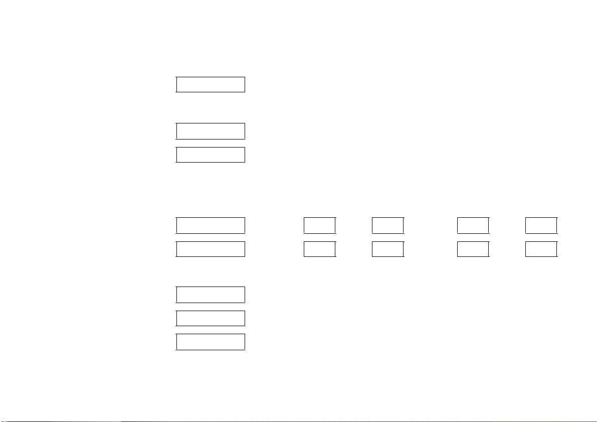
For key with retractable blade 3, press the
button to extend.
6 Further information – see pages 44, 45,
vehicle recomm issioning – page 190.
Picture no: 18079s.tif
To unlock the vehicle and
open the doors:
With key in lock
turn key towards front of
vehicle or press button q
on the remote control 3,
pull door handle and open door or
sliding d oor 3.
Unlocking the door from inside:
Pull up on lock button.
6 Sliding door 3 – see page 54.
door locks, child safety locks 3 –
see page 46,
electronic immobilizer – see page 45,
radio frequency remote control 3 –
see page 47,
central locking system 3 – see page 51,
Vauxhall alarm system 3 – see page 58.
Page 8
3In Brief
Picture no: 18080s.tif
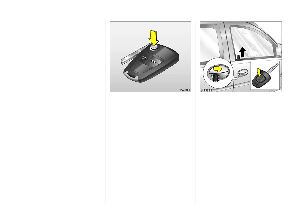
To unlock and open ta ilgate 3:
Turn key to horizontal position or
press bu tto n q on the remote
control 3,
press bu tto n and
open tailgate upwards.
When using the remote control, the tailg ate
is only unlocked if the key slot in the button
is in the horizontal position.
If the key slot is in the vertical position, the
tailgate is always locked.
6 Radio frequency remote control 3 –
see page 47,
central locking system 3 – see page 51,
Vauxhall alarm system 3 – see page 58,
tailgate 3 – see page 55.
Picture no: 18081s.tif
To unlock and open rear doors 3 :
Turn key to vertical position or
press button q on the remo te
control 3,
pull handle and open rear door.
To open the left rear, pivot the
handle on th e inside.
When using the remote control, the rear
doors a re only unlocked if th e ke y slot in the
lock is in the vertical position.
If the key slot is in the horizontal position,
the rear doors are always locked.
6 Radio frequency remote control 3 –
see page 47,
central locking system 3 – see p age 51,
Vauxhall alarm system 3 – see page 58,
rear doors 3 – see page 56.
Picture no: 13189s.tif
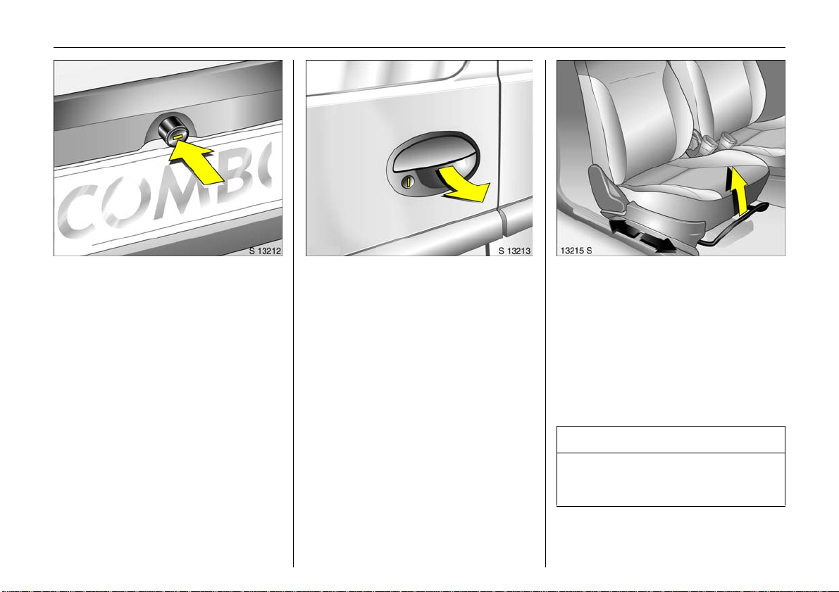
To adjust fron t seat 3:
Pull handle,
slide seat,
release handle,
allow seat to audibly latch into
position
N ever adjust the seat wh ilst drivin g. It c ould
move in an uncontrolled manner when the
handle ha s been pulled.
6 Seat position – see page 63.
9 Warnin g
Important: Do not sit nearer than 10
inches (25 cm) from the steering wheel, to
permit safe airbag d eployment.
Page 9
4In Brief
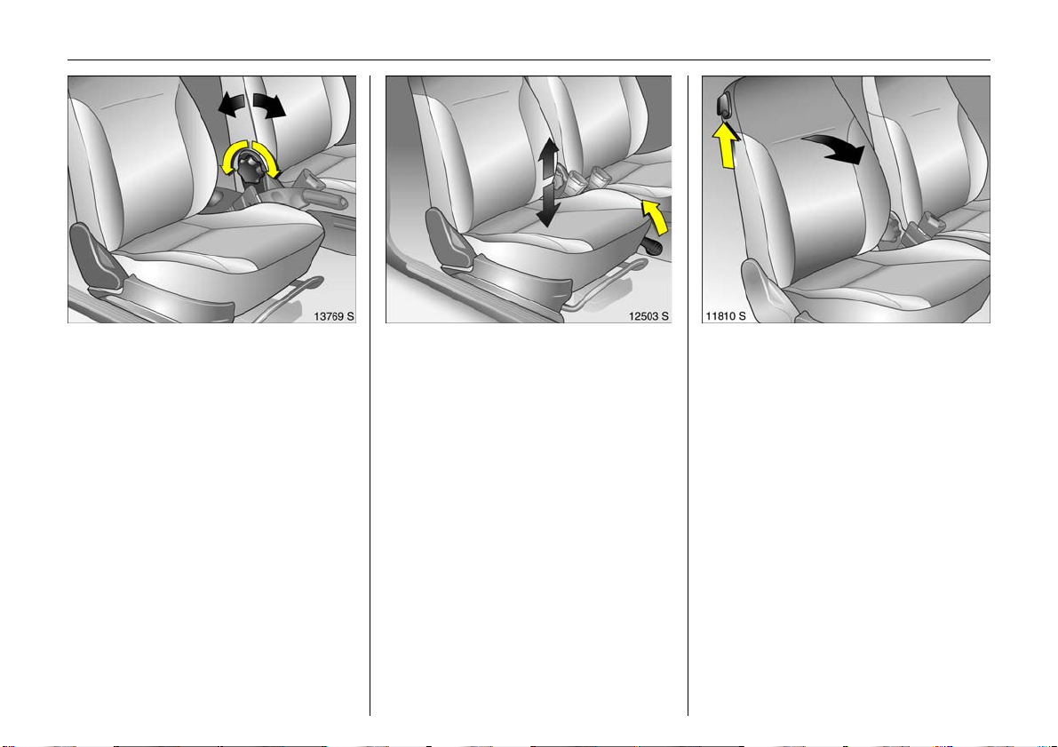
Picture no: 13714s.tif
To adjust front seat backrests:
Turn handwheel
Move sea t backrest to suit seating position.
Do not lean on seat backrest whilst
adjusting it.
6 Seat position – see pag e 63.
Picture no: 12429s.tif
To adjust front seat height 3:
Pull lever at side
Lift lever and relieve some weight from seat
to raise it or press down on seat with body
weight to lowe r it.
Nev er adjust the driver’s seat whilst driving.
It could move in an uncontrolled manner
when the lever has been pulled.
6 Seat position – see page 63.
Picture no: 11536s.tif
To fold front seat backrest 3:
Raise lever
To enter and le ave the rear seat area, tilt
front seat back forwards.
6 Seat position – see page 63.
Page 10
5In Brief
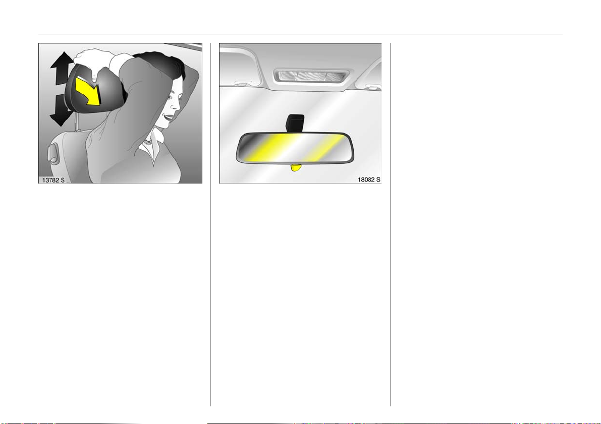
Picture no: 13781s.tif
To adjust height 3 of front and
outboard rear head restraints:
Tip forward to release,
hol d and adjust h eight,
release
6 H ead restraint position – see page 63,
further information, removal –
see page 64,
centre rear head restraint 3 – see page 64.
Picture no: 18082s.tif
To adjust interior mirror:
Swivel mirror housing
Swivel lever on underside of mirror housing
to reduce dazzle at night.
Page 11
6In Brief
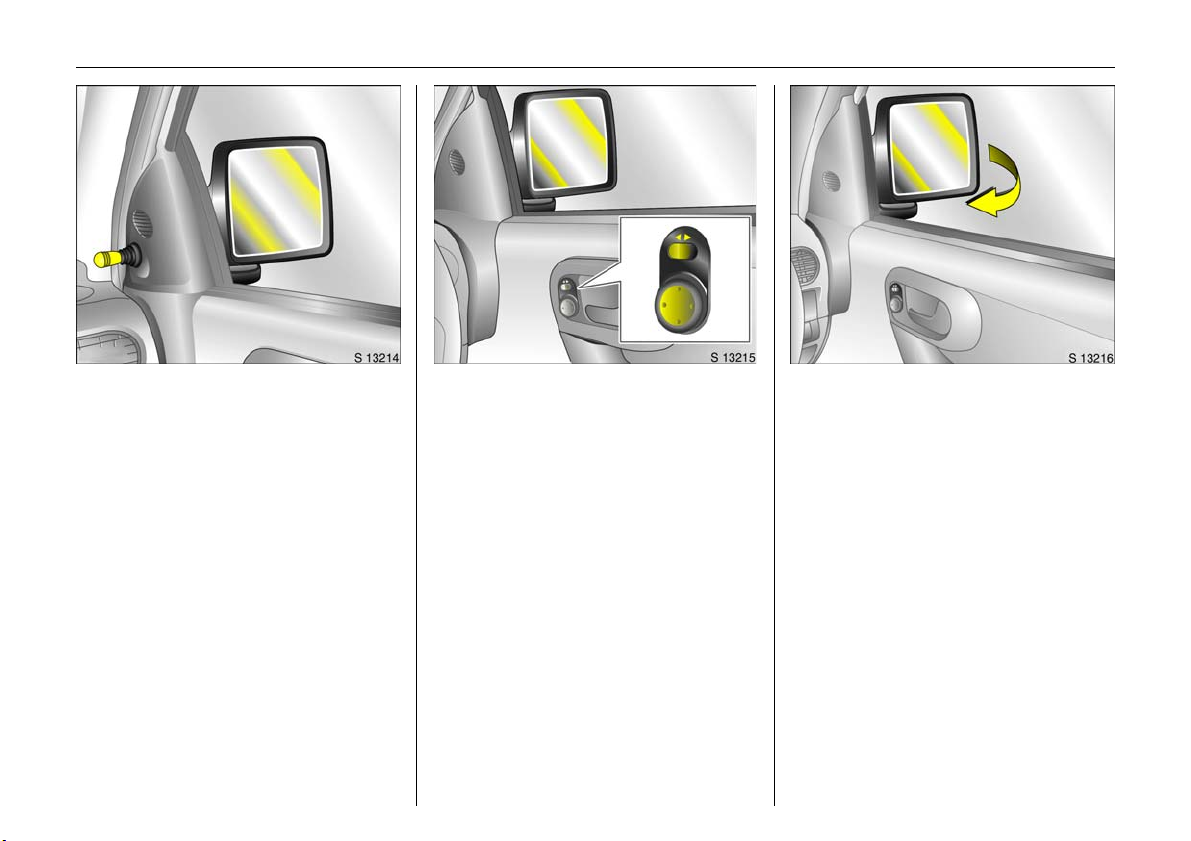
Picture no: 18083s.tif
To adjust exterior mirrors:
Swivel lever in required direction
6 Further information, aspherical exterior
mirror 3 – see page 91.
Picture no: 18084s.tif
Electrically adjustable
exterior mirrors 3:
Four-way switch in driver’s door
Togg le switch to left or right: four-way
switch moves appropriate mirror.
6 Additional instructions, aspherical
exterior mirror 3 – see page 91,
heated exterior mirror 3 – see page 16.
Picture no: 18085s.tif
To retract exterior mirrors
The mirrors retract when subject to slight
pressure.
Return the mirrors to the driving position
before starting-off.
Page 12

7In Brief
Picture no: 13190s.tif
Fitting seat belt:
Draw seat belt smoothly from
inertia reel,
gu id e ov er sh ould e r
and engage in buckle
The belt must not be twisted at any point.
The lap belt must lie snugly against the
body. The backrest must not be tilted back
too far (recommended tilting angle
approx. 25°).
To release belt, press red button on belt
buckle.
6 Safety belts – see pages 76 to 82,
airbag systems 3 – see page 82,
seat position – see page 63.
Picture no: 15678t.tif
Disengaging steering column
loc k:
To release the lock,
move the steering wheel slightly
and turn the key to position 1
Positions:
0 = Ignition off
1 = Steering released, ignition off
2 = Ignition on,
Diesel engines: preheating
3= Start
6Starting – see page 18,
electronic immobilizer – see page 45.
Remove key and lock steering wheel –
see page 19.
Picture no: 18086s.tif
Steerin g wheel adjustment 3 :
Swivel lever down,
adjust height,
swivel leve r u p,
engage
Adjust steering wheel only when vehicle is
stationary and steering column lock is
released.
6 Air bag sy ste ms 3 – see page 82.
Page 13
8In Brief
Page 14

9In Brief
Page
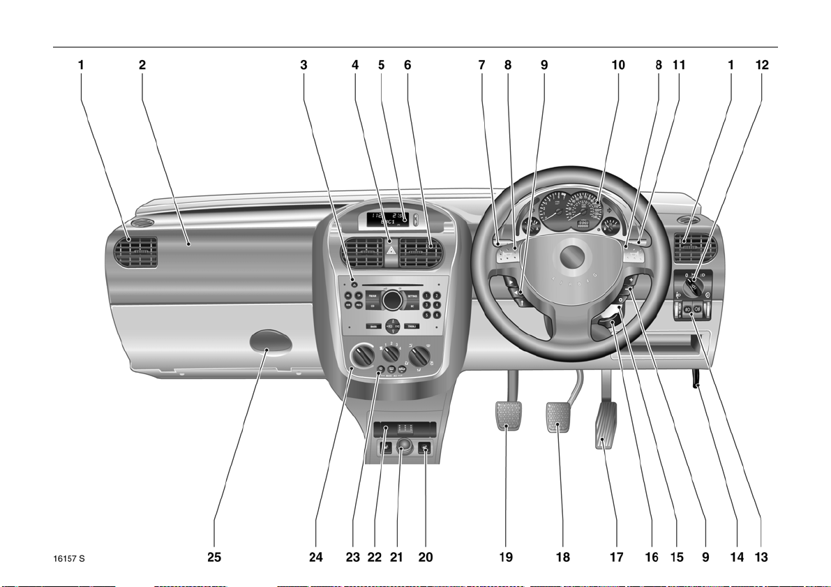
1 Side air v ents ................. .... ......... ... 102
2 Front pa ssenger airbag 3 .............. 82
3 Infotainment system 3 . .... ............. . 42
4 Haza rd warning lights ...... .... ..... ..... 14
LED for Vauxhall alarm system 3 ..59
5 Display3 for tim e, date,
outside temperature,
infotainment system 3 ..... ............. . 3 1
6 Centre air v ents .... .... ......... ......... .... 102
7 Turn signals, headlight flash,
dipped beam, main beam ............ . 13
8 Horn ........ ..... .... ..... ............. .... ..... .... .. 14
9 Infotainment system
remote control 3 .. .... ..... ............. .... . 2 2
10 Instruments ...... ..... .... ..... .... ............. . 24
Pa ge
11 Windscreen wiper,
windscreen wash system,
rear window wash system 3 .... ....... 15
12 Light switch .................. .... ......... .13, 9 3
13 Headlight range adjustment 3 ..... .. 94
Fog tail light ........ ..... .... ......... ......... .. 95
Front fog lights 3 ......... ......... ......... .. 94
Instrument illumination ........ ......... .. 95
14 Bonne t rele ase lever . .... ............. ..... . 6 1
15 Starter switch with
steerin g column lock..... .... ..... ......... .... 7
16 Stee ring wheel adjustm ent 3 ... ..... ... 7
17 Ac celera tor pedal ............ ..... 117, 118
18 Brake peda l .............. .... .... ..... 117, 1 29
19 Clutch ped al 3 .... ..... ............. .... .... 1 18
Page
20 S eat heating 3 ... .............. .... ..... .... 103
21 Accessory socket or
cigare tte lighter ...... ......... ......... ...... 71
22 Ashtray 3 ............ ..... .... ......... ......... .. 72
23 Air conditioning system 3 ... ......... 107
Heated rear w indow 3 .... ........ 16, 103
Air recirculation system 3 ......... .... 107
24 Heating and v entilation system .. 101
25 Glove compartment ... ..... ......... ...... 73
Page 15

10 In Brief
Control indicators
X Seat belt 3,
see page 24.
> Front fog lights 3 ,
see pages 24, 94.
A Engine electronics,
transmission electronics 3,
electr onic imm obilize r,
diesel fuel filter 3,
see pages 24, 45, 126.
Z Exhaust emissi ons 3 ,
see pages 25, 45, 125.
v Airbag systems 3,
bel t tensioners,
see pages 77, 86.
I Engine oil pressure,
see page 25.
O Turn signal l ights,
see page s 14, 25.
C Main beam,
see page s 13, 26.
! Preheating for diesel engines 3,
di esel part icle filte r 3,
see page 26.
T Easytronic winter program 3,
see page s 113.
r Fo g tai l ligh t,
see page s 26, 95.
p Alternator,
see page 26.
R Brake system,
clutch syst em 3,
see page 26.
u Anti-lock Brake System 3,
see page 131.
S Engine oil level 3,
see pages 27, 182.
EPS Electr ic power-assisted steering 3,
see page 27.
Y Fue l level,
see pages 27, 30, 143.
Page 16

11In Brief
Lighting
Lig ht switch,
sw itc h p o s it ions,
see pages 13, 93,
7 Lights off,
8 Parking l ights,
9 Dippe d beam, main beam.
0 Courtes y lig ht,
see page 96.
C Dippe d beam, main beam,
see page 13.
O Turn signal lights,
see page 14.
> Front fog lights 3 ,
see page 94.
r Fog t ail lig ht,
see page 95.
k Instrume nt illu m ination,
see page 95.
? Hea dlight range adjustment 3,
see page 94.
¨ Haza rd wa rning lights,
see page 14.
Climate control
x Air flow,
see page s 104.
Air distribut ion,
see page s 104,
V To windscreen and
front door window s,
J To windscreen, front
door windows
and footwell,
K To footwell,
L To head area and footwell,
M To head area.
Ü Heated rear window 3,
see pages 103.
n Air conditioning system 3,
see page 107.
4 Air recircul ation system 3,
see page 107.
ß Heated front seats 3,
see page 103.
Page 17

12 In Brief
Windscreen wiper
Stalk positions,
see page 15,
§ Off,
$ Timed interva l wip e,
% Slow,
& Fast.
Date, time, information display,
infota inment sy s tem
Inform ation d isp lay 3,
see page 31.
Ö On button for date
and time,
; Setting buttons for date and time
Infotainment system
remote control 3,
see page 22.
Miscellaneous
p Central l ocking sy stem 3,
locking – see page 51.
q Central l ocking sy stem 3,
unlocking – see page 51.
j Horn,
see page 14.
T Easytronic winter program,
3,
see pages 113.
+ Fir st- aid kit (cu sh ion) 3,
see page 148.
¨ Warning tri angle 3,
see page 148.
Page 18
13In Brief
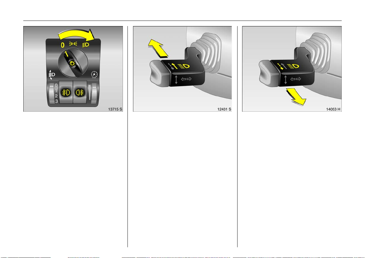
Picture no: 13715s.tif
Light switch:
7 =Off
8 = Parking lights
9 =Dipped or
main beam
0 Pu s h = Cou rtes y l ig ht
> Press = Front fog lights 3
r Push = Fog tail light
6 Further information – see page 93,
headlight warning device – see page 20,
headlight range adjustment 3 –
see page 94,
daytime running lights 3 – see pag e 93.
Picture no: 12431s.tif
Main and dipped beam switch:
Main beam = Push stalk
forward
Dipped beam = Push stalk
forw ard again
The blue control indicator C is illuminated
when main b eam is on.
Picture no: 14053h.tif
Headlight flash:
Pull stalk towards steering wheel
Page 19
14 In Brief
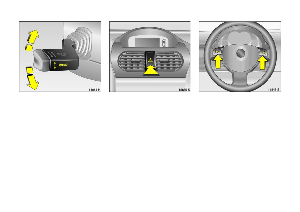
Picture no: 14054h.tif
Operating turn signal lights:
Stalk in rest position
Righ t = Up
Left = Down
When the stee ring wheel is turne d back, the
stalk automatically returns to its original
position. This will not happen when making
a minor steering manoeuvre such as
changing lane.
When lane chang ing, move sta lk to
res ista nce point. W hen re leas ed , the stalk
will spring back.
Picture no: 15865s.tif
Hazard warning lights:
On = Press ¨
Off = Press ¨ again
To aid location of the pushbutton, the red
surface is illuminated when the ignition
switched on. When the button is pressed,
its control indicator flashes in time with the
hazard warning lights.
Picture no: 11548s.tif
Horn operation:
Press j
6 Airba g syst e ms 3 – see page 82,
Remote control for
infota inm ent system 3 – see page 22.
Page 20
15In Brief
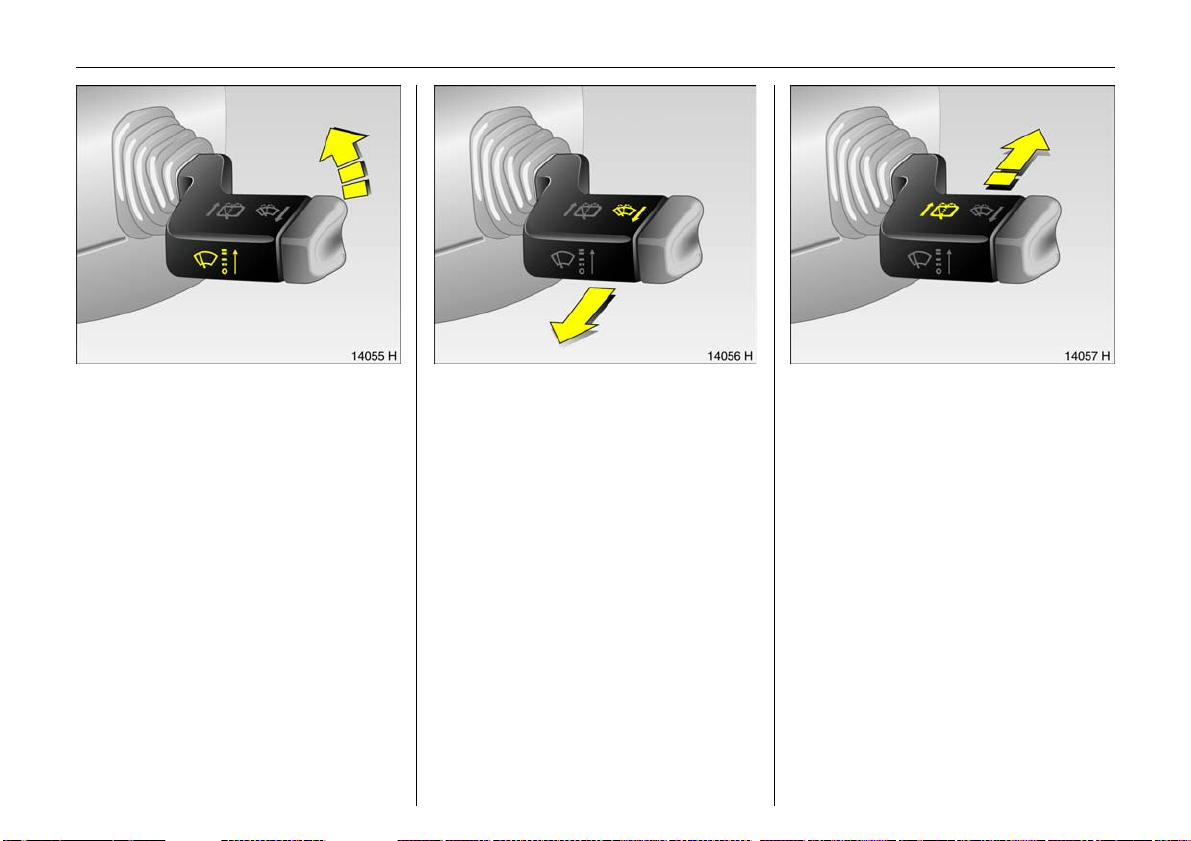
Picture no: 14055h.tif
Windscreen wiper:
Stalk up
§ = of f
$ = Adjustable timed interval
% = slow
& = fa st
Setting wiper interval to a value between 2
an d 15 se conds:
Stalk to interval switching $,
Stalk to § ,
wait for desired interval,
Stalk back to interval switching $ .
The interval remains stored until the next
change or until the ignition is switched off.
Switching the ignition on and m oving the
stalkto $ sets the interval to 7 seconds.
Picture no: 14056h.tif
Operating windscreen wash
system:
Stalk toward steering wheel
The wiper will swipe for a few strokes.
6 Further information –
see pages 188, 194.
Picture no: 14057h.tif
Operating rear window wiper 3
and wash systems 3 :
Wiper on = Push stalk forward
Wiper off = Pull stalk towards
steering wheel
Wash = Push stalk forward
an d hold
The rear window wiper swipes in timed
interval mode.
The wip er will swipe for a few strokes when
washing.
6 Further information –
see page s 188, 194.
Page 21
16 In Brief
Ü Board Computer 19,5° 19:36
BC 1 All values
BC 2
Timer
1
257.0 miles
Ø40mph
7.0 ga l s
8
Ø 31.0 mpg l
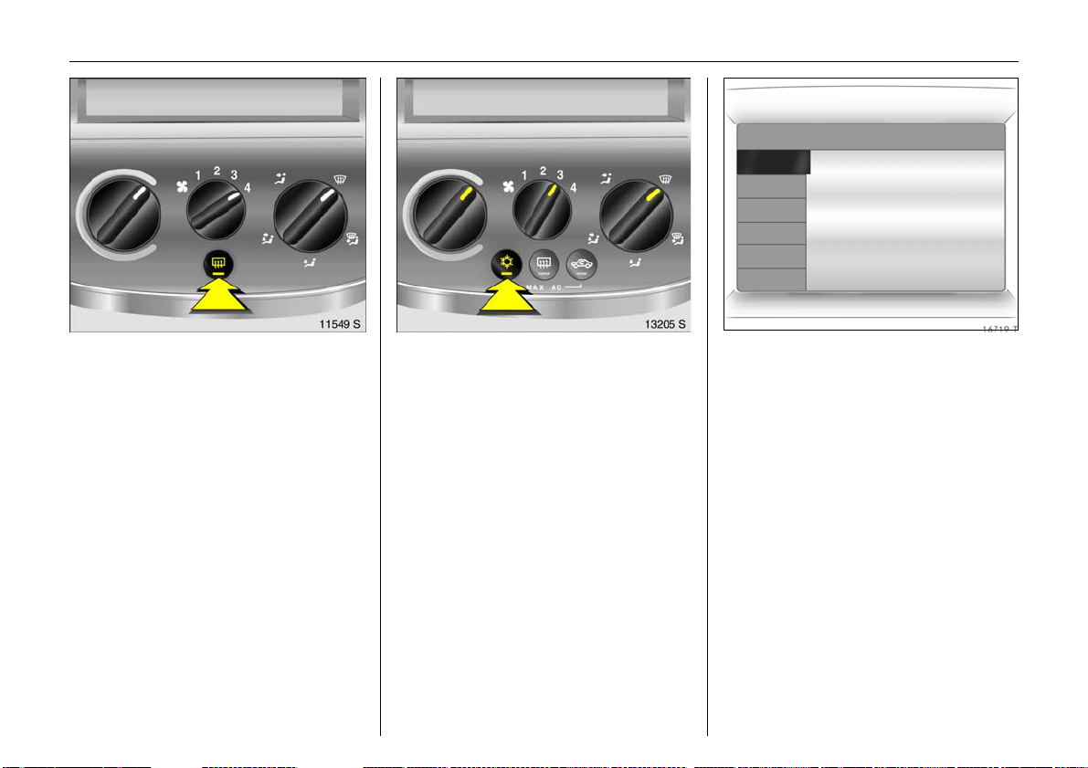
Picture no: 11549s.tif
Heated rear window 3,
heated exterior mirrors 3:
On = Press Ü
Off = Press Ü again
Rear window and exterior mirror heating
with ignition switched on. Control indicator
in switch.
6 Further information – see page 103.
Picture no: 13205s.tif
Clearing misted or icy windo ws:
Turn rotary knobs for
temperature and
air flow clock wis e,
set air distribution to V,
press air conditioning switch n 3
Close centre air vents; push sliders inwards.
Direct side air vents towards d oor windows.
6 Climate control – see page 101,
air conditioning3 – see page 107.
Picture no: 16719t.tif
Information display 3:
Presents information
–Time,
– Outside temperature,
–Radio3 or da t e,
– Navigation 3 ,
– T elep hon e 3,
–Trip computer3.
6 Informa tion Display – see page 31.
Page 22
17In Brief
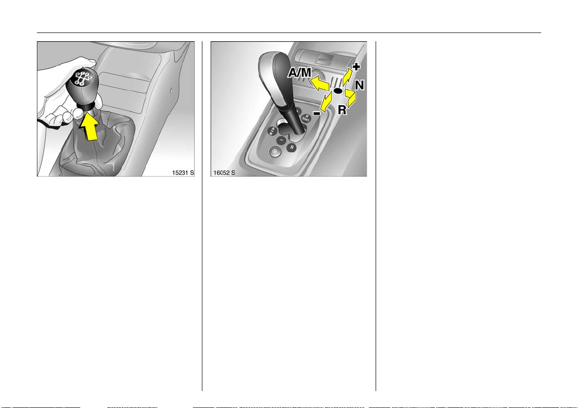
Picture no: 15120s.tif
Manual transmission:
Reverse gea r: With vehicle stationary, three
seconds after de-clutc hing pull the ring up
and and engage gear.
If the gear does not engage, set the lever in
neutral, release the clutch pedal and
depress again; then repeat gear selection.
Picture no: 12466s.tif
Easytronic 3 :
N = Neutral/start position
o =Driving position
(centre position)
+ =Higher gear
- =Lower gear
A/M = Switch between
automatic and
manual mode
R =Reverse
(with selector lever lock)
To move the selector lever from N to R
pres s th e bu t t o n o n th e lev er .
Only start in N with footbrake applied.
6 Further information – see page 113.
Page 23
18 In Brief
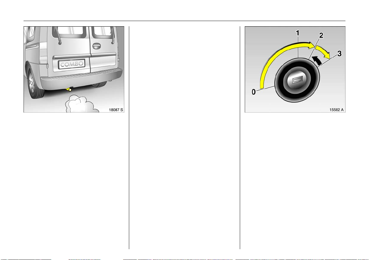
Picture no: 18087s.tif
Exhaust gases are poisonou s
Exhaust gases contain carbon monoxide,
which is extre mely poisonous but is
odourless and colourless.
Therefore never inhale exhaust gases, and
never run the engine in an enclosed space.
Avoid driv ing with an open load
compartment. Otherwise, exhaust gases
could pe netrate the interior.
Befor e sta rti ng -o ff, ch e ck :
z Tyre pressure and tyre condition -
see page s 134, 205.
z Engine oil level and fluid levels in engine
compartment – see pages 181 to 188.
z All windows, mirrors, exterior lighting
and number plates are free from dirt,
snow and ice and operational.
z Do not place any objects in front of the
rear window, on the instrument panel or
in the area in w hich the airbags inflate.
z Seats, seat b elts and mirrors are
correctly adjusted.
z Check brakes.
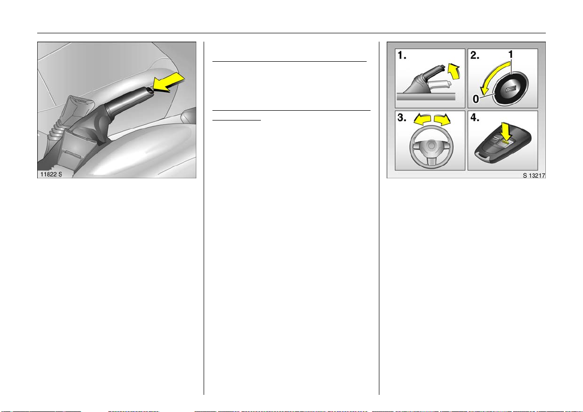
Picture no: 15582a.tif
To start the engine:
Depress clutch and brake pedals,
Easytronic 3 in N,
do no t accelerate,
petrol engine: key to 3;
diesel engine: key to 2,
when control indicator !
goes out1), turn key to position 3;
release key once engine is
running
To rep eat the start procedure or switch off
the engine, turn the key back to 0 .
To switch on the ignition, turn the key to 2.
6 Electronic imm obilizer – see page 45,
further information – see pages 118, 143.
1)
Preheating system switches on only if outside
temperature is low.
Page 24
Warning b uzzers
When starting the engine or w hile driving:
z if seat belt is not fastened 3,
z if a specified m aximum speed is
exceeded 3.
When parking the vehicle and opening the
driver’s door:
z when the ignition key is in the starter
switch,
z if parking lights / dipped beam are on,
z if the turn signal stalk is engaged.
19In Brief
Picture no: 11554s.tif
To release the handbrake:
Raise lever slightly,
press lock bu tton,
lower lev er fully
In order to reduce the operational forces,
depress the footbrake at the same time.
And now "H ave a good journey!"
Drive carefully, economically and with the
environment in mind. While driving, do not
do anything that could distract you.
6 Brak es – see page 128
Picture no: 15758t.tif
Parking the vehicle:
Apply ha ndbrake firmly,
turn engine off and remove key,
lock steering wheel,
lock doors
To lock and activate the Vauxhall alarm
system 3, turn the key in any unlocked
door toward the rear of the vehicle or press
button p on the remote control. L ock load
compa rtment. To arm the mechanical antitheft locking system press button p twice.
6 Further information – see pages 45, 117,
radio frequency remote control 3 –
see page 47,
central locking system 3 – see page 51,
Vauxhall alarm system 3 – see page 58,
Vehicle decommissioning – see page 190.
Page 25
20 In Brief
Advice when parking:
z Always apply ha ndbrake firmly . On
slopes apply the handb rake as firmly as
possible.
z With manual transmission, select first
gear or reverse gear, with Easytronic 3
move selector le ver to c entre position
before switching ignition off.
z Close the wind ows.
z On vehicles with Easytronic 3 the control
in d i ca to r R flashes for a few seconds
after the ignition is switched off if the
handbrake has not been applied.
z Turn steering wheel until lock is felt to
engage (anti-theft protection).
z Engine cooling fan may run on after the
engine has been switched off.
z Do not park vehicle on easily ignitable
surfaces as the hot exhaust system
temperatures could cause the surface to
ignite.
6 Further information –
see pages 188, 190.
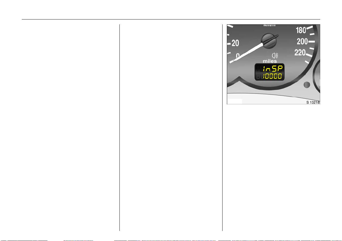
Picture no: 14419S.tif
Service work,
Maintenance
We recommend that you entrust all work to
your Vauxhall Authorised Repairer, who
can p rov ide you with reliable service and
correctly perform all work according to
factory instructions.
6 If you have a problem – see page 178,
Service interval display – see page 180.
Page 26
21In Brief
Genuine Vauxhall Parts and
Accessories
We recommend that you use "Genuine
Vauxhall Parts and Accessories" and
conversion parts approved expressly for
your vehicle type. These parts have
undergone special tests to establish their
reliability , safety and specific suitability for
Vauxhall vehicles. Despite continuous
market monitoring, we cannot assess or
guarantee these attributes for other
products, ev en if they have been granted
approva l by the relevant authorities or in
some other form.
"Genuine Vauxhall Parts and Accessories"
and conversion parts approved by
Vauxhall can be obtained from your
Vauxhall Authorised Repairer, who c an
provide comprehensive advice on
permitted tec hnical changes and ensure
correct installation.
9 Warning
Carry out regularly the checks
recommended in the individual sections
of this Owner’s Manual.
Ensure that y our vehicle is se rv iced as
indicated by the service interval display.
We recommend that you consult your
Vauxhall Authorised Repairer.
Have faults remedied without delay!
Consult a workshop. We recommend your
Vauxhall Authorised Repairer. If
necessary, interrupt your journey.
6 Maintenance – page 180.
That was a brief overview of the
most imp ortan t in forma t io n for
your first trip in your Combo.
The othe r pages of this chapter
contain a d escription of some
interesting functions in your
vehicle.
The re ma in ing ch apte rs of the
Owner’s Manual contain
important information on
operation, safety and
maintenance as well as a
complete index.
Page 27
22 In Brief
Ü Board Computer 19,5° 19:36
BC 1 All values
BC 2
Timer
257.0 miles
Ø40mph
7.0 ga l s
Ø 31.0 mpg
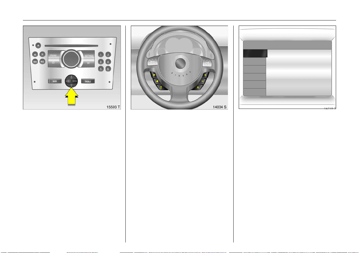
Picture no: 15593t.tif
Operating via the information
dis play m enu s
Th e menu options are sele cted via th e
menus and w ith the button / four-way
button or the multi-function button of the
infotainmen t syst em 3 or via the buttons 3
on the s teering wheel. The men u options
appear on the display.
To select with four-way button:
Press four-way button up, down, right or
left.
To select with the multi-function button
Picture no: 14034s.tif
(rotary knob above the four-way button,
see page 34):
Press and turn multi-function button.
To exit a menu, turn the multi-function
button left or rig ht to Return or Main and
se lect.
To select with steering wheel buttons:
Select menu options via the menus using
the buttons.
For further information, see infotainment
sy ste m in structions.
Picture no: 16719t.tif
Trip computer 3
Th e trip compu ter s hows ve h icle d ata that
is continually recorded and evaluated
electronically.
Functions:
z Range
z Instantaneous consumption
z Distance travelle d
z Average spee d
z Effective consumption
z Average consumption
z Sto p watch
Page 28
23In Brief
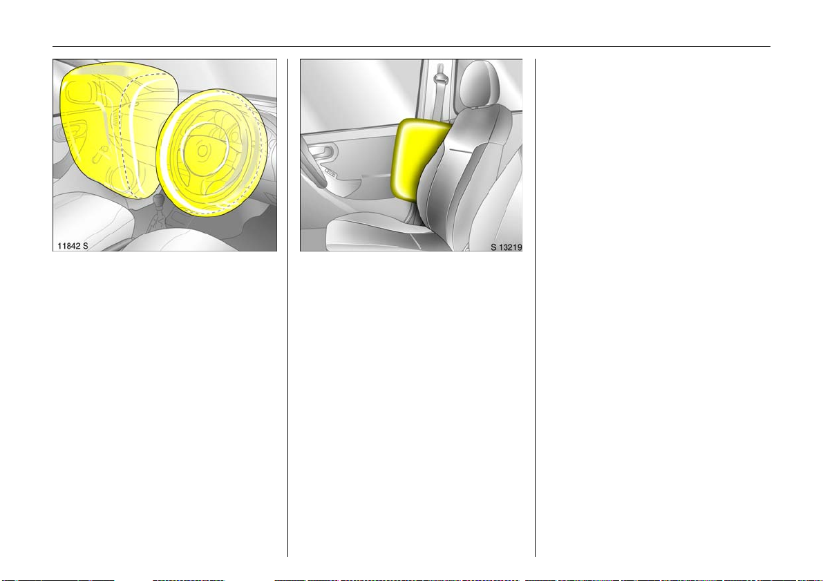
Picture no: 11600s.tif
Vauxhall Full Size airbag system
The Vauxhall Full Size airbag system
comprises several individual systems.
Front airb ag system 3
The front airbag system will be triggered in
the event of a serious ac cident involving a
frontal impact and forms safety cushions
for the driver and front passenger. The
forward movement of the driver and front
passenger is checked and the risk of
injuries to the upper body a nd head
thereby substantially reduced.
Side airb ag system 3
Picture no: 18088s.tif
The side airbag system trigge rs when a
side-on collision occurs and provides a
safety barrier for the driver and/or
passenger in the respective front door
area. This reduces the risk of injury to the
upper body considerably in case of a side
impact.
6 Further information – see page 82.
Page 29
24 Instruments
Instruments
Control indicators .... ..... ......... ........ ...... 2 4
Instrument display ..................... .... ..... . 2 8
Information display . ..... .... ............. ..... . 3 1
Outside temperature .... .... ..... ............. . 32
Triple information display......... .... ..... . 3 3
Radio reception 3 ......... ............. .... ..... . 4 2
Infotainment system 3 ..... ..... ............. . 42
Remote control 3 for infotainm ent
sy ste m 3 and information display .. 42
Mobile telephones and radio
equipment (CB) 3 ...... .... ..... .... .......... 43
Control indicators
The control indicators described he re are
not p resent in all vehicles. The description
applies to all instrument versions.
X
Seat belt 3
If the control indicator illuminates after the
ignition is switched on (with warning
buzzer), fasten seat belt - see page 79.
>
Front fog lights 3
The control indicator is illuminated when
the front fog lights are on - see page 94.
A
E n gin e el ect ronics,
tr a n sm issi on ele ct r o ni cs 3,
ele ctronic immob iliser, diesel fuel fi lter 3
The control indicator illuminates for a few
seconds when the ignition is switched on.
Illuminates when the engine is running
Fault in engine electronics or transmission
electronics. Electronics switch to
emergency running programme, fuel
consumption may increase and driveability
of the vehicle may be impaired –
see page 126. Consult a work shop
immediately. We recomm end your
Vauxhall Authorised Repairer.
Flashes when the ignition is on
Fault in the electronic immobiliser system;
th e engine c annot be started –
see page 45.
Page 30
Z
Exhaust emission
The control indicator illuminates when the
ignition is switched on and g oe s out shortly
after the engine starts.
Illuminates when the engine is running
Fault in emission control system. The
permitted emission limits may be
exceeded. Consult a workshop. We
recommend your Vauxhall Authorised
Repairer.
If it flashes when the engine is running:
Fault that can lead to destruction of the
catalytic converter is indicated; see
page 125. Consult a workshop
immediately. We recommend your
Vauxhall Authorised Repairer.
v
Airbag systems 3,
Belt ten sione rs
see pages 78, 86.
I
Engine oil p ressure
The control indicator illuminates when the
ignition is switched on and goes out shortly
after the engine starts.
Illuminates when the engine is running
Engine lubrication may be interrupted. This
may result in dam age to the engine and/or
locking of the drive wheels:
25Instruments
1. Move out of the flow of traffic as quickly
as possible, without impeding other
vehicles.
2. Depress clutch.
3. Move gearshift lever to neutral, or with
Eas ytro nic 3, place selector lever in N.
4. Switch off ignition.
9 Warnin g
When the engine is off, considerably
more force is ne eded to brake and stee r.
Do not remove key until vehicle has come
to a standstill, otherw ise the steering
column lock could engage unexpectedly.
Consult a workshop. We recommend your
Vauxhall Authorised Repairer.
O
Turn signal lights
When the turn signal is activated, the
corresponding control indicator flashes.
Rapid flash: A turn signal bulb is faulty.
Both control indic ators flash when the
hazard warning lights are activated.
Bulb replacement - see pag e 167.
Page 31

26 Instruments
C
Main bea m
The control indicator is illuminated when
main beam is on and during headlight
flash - see page 93.
!
Preheating for diesel engines 3,
diesel part icle filte r 3
Illuminated
Prehe ating system active, switches on o nly
if outside temperature is low.
Flashing (with diesel particle filter)
Diesel particle filte rs m ust be clea ned.
Continue driving and as soon as the road
and traffic conditions permit it, increase
speed to more than 25 m ph (40 km /h), at
which point diesel particle filter cleaning
will start. The control indicator goes off as
soon as cleaning is complete. We
recommend leaving the ignition switched
on during th e c le an ing .
Further information – see pa ge 127.
T
Easytronic winter program 3
Contro l indicator is illuminate d whe n win ter
program is e nabled.
Further information – see pa ge 113.
r
Fog t ail li ght
The control indicator is illuminated when
the fog tail light is on - see page 95.
p
Alternator
The control indicator illuminates when the
ignition is switched on and goes out shortly
after the engine starts.
Illuminates when the engine is running
Sto p th e v ehicle a nd switch of f th e e ng ine.
The battery is not being charged. Engine
cooling may be interrupted. Contact a
workshop. We recommend your Vauxhall
Authorised Repairer.
R
Brake system,
clutch system 3
The control indicator illuminates when the
ignition is switched on if the handbrake is
applied or if the brake or c lutch fluid level 3
is too low. Further information - see
pages 130, 186.
9 Warnin g
If it illuminates when the handbrak e is not
applied: Stop the vehicle; interrupt y our
journey immediately. Consult a
workshop. We recommend your Vauxhall
Authorised Repairer.
On vehicles with Easytronic 3 control
indicator R fl a s hes for a fe w se co nd s af ter
the ignition is switched off if the handbrake
has not been applied.
Page 32

27Instruments
u
Anti-lock Brake System 3
see page 131.
S
Eng ine oi l level 3
Illuminated: Low engine oil level. Check oil
level and top up as necessary –
see page 182.
1)
EPS
E lec tr ic p ow er -assi st ed st eeri n g 3
The control indicator illuminates for a few
seconds when the ignition is switched on.
Illumination while driving indicates a fault.
Driving may be continued. More force is
required for steering. Consult a workshop.
We recommend your Vauxhall Authorised
Repairer.
Y
Fuel le ve l 3
Illuminated: Low fuel level. Fuel gauge in
re ser ve ar ea .
Flashing: Fuel supply used up, fill tank
immediately.
Never let the tank run dry!
Erratic fuel supply can cause catalytic
converter to overheat – see page 124.
Diesel e ng ines: If the tank is run dry, bleed
the fuel system as described on page 143.
Transmission display 3
Display of current g ear or m ode with
Easytronic 3.
Further information – see page 111.
1)
EPS = Electric Power -assisted Steering.
Page 33

28 Instruments
Trip odometer
To return to zero, depress reset knob with
ignition switched on and trip odometer
display activated.
Vehicles with clock in odometer
To set to zero, hold reset knob down for
approx. 2 seconds with ignition switched
on and trip od om eter activated.
To switch between trip odometer and clock
display 3 give reset knob a brief press – se e
next page.
Service interval display, see page 180.
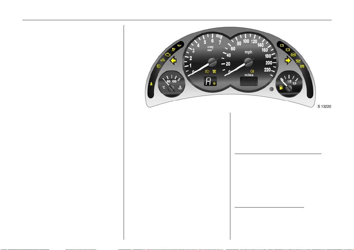
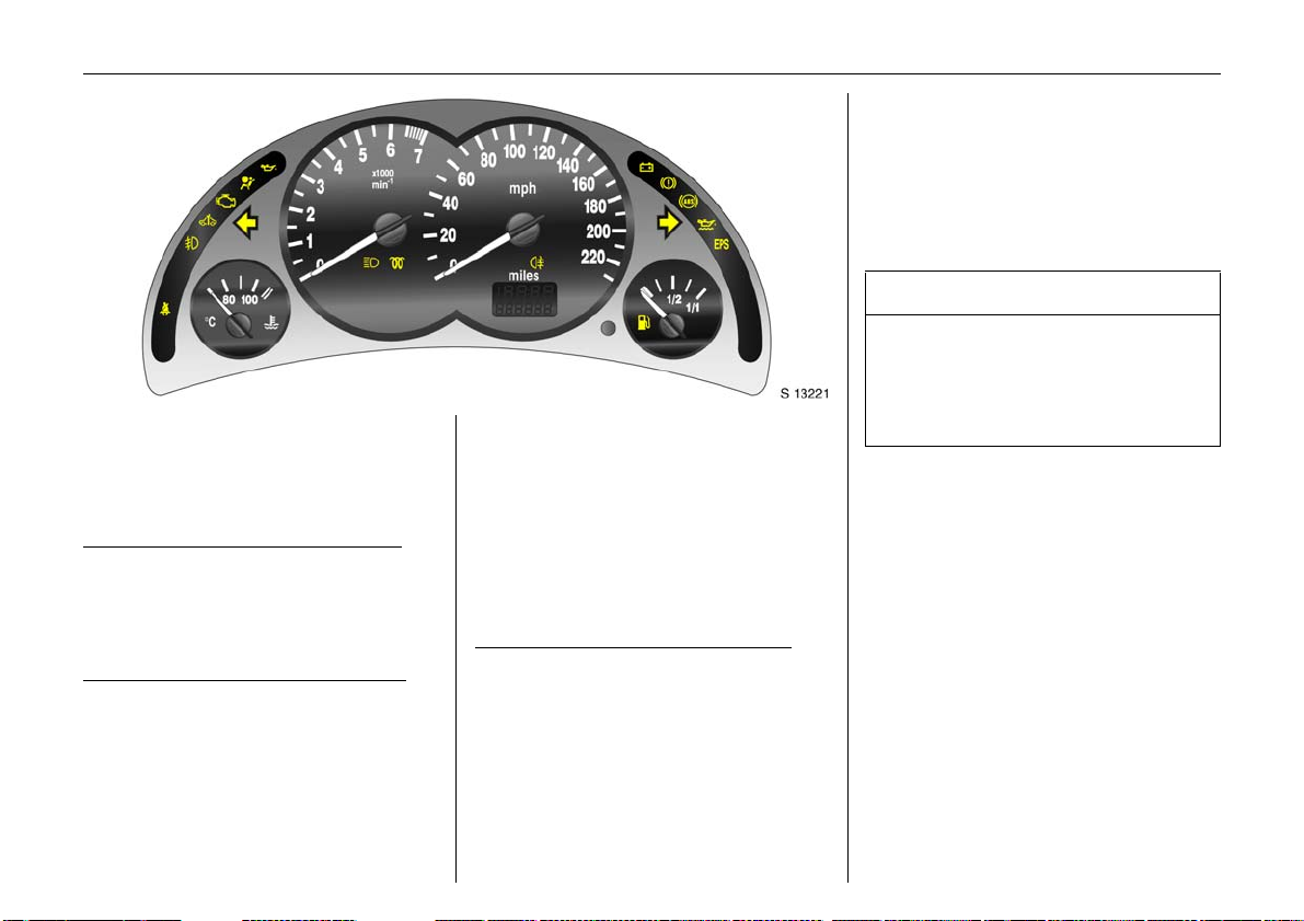
Instrument display
Tachometer
Indicates engine speed.
Warning zone: M aximum p ermissible
engine speed ex ceeded ; dange r to engine.
Speedometer
Indicates the vehicle speed.
Odom et er
Records the miles driven.
With the ignition switched off, briefly press
the reset knob to display the number of
miles driven for approx. 15 seconds.
Page 34

Time di sp lay in odometer 3
To switch between trip odometer and time
display 3 give reset knob a short press.
When the veh icle lights are on, th e
brightness of the display ca n be adjusted
using the right-hand adjuster wheel k
below the light switch – see page 96.
29Instruments
Setting the time
With time displayed, press reset knob in
instrument:
Press for approx. 2 seconds:
Hours flash
Pre ss br ie fly
Set hours
Press for approx. 2 seconds
Minutes flash
Pre ss br ie fly
Set minutes
Press for approx. 2 seconds
Clock is started .
Page 35

30 Instruments
For physical reasons, the engine
temperature gauge shows the coolant
temperature only if the coolant level is
adequate.
During o peration the system is pressuris ed.
The temp erature ma y there fore rise briefly
to over 100 °C.
Coola nt te mpe rat ure display
Pointer in zone at
left = Engine operating
temperature not y et
reached
Pointer between
the zones = Normal operating
temperature
Pointer in right
zone
(warning zone) = Temperature too
high :
Stop vehicle and
switch off engine.
Danger to engine.
Check coolant level
imme diately, see
page 185.
Fuel gauge
Pointer in red
warning
zone or Y
illuminated = Reserve level.
Pointer in red
warning
zone or Y
flashing = Refuel immediately
Never run the tank dry!
Diesel engines: If the tank is allowed to run
dry, bleed the fuel system as described on
page 143.
Because of the fuel remaining in the tank,
the amount of fuel required to fill the tank
may be less than the specified tank
capacity.
– see page 122.
Page 36

12:01 17,0°C
FM 3 90,6MHz
REG A S RDS TP
Ü Board Computer 19,5° 19:36
BC 1 All values
BC 2
Timer
1
257.0 miles
Ø40mph
7.0 ga ls
8
Ø 31.0 mpg
31Instruments
Infotainment system – see infotainment
system op erating instructions.
An F in the display indicates a fault. Have
the cause of the fault remedied. We
recommend that you consult your Vauxhall
Authorised Repairer.
Information display
Tripl e info rm ation d isplay 3
Display of time, outside temperature and
date/infotainment system (when it is on).
When the ignition is off, the time, date and
outside temperature can be made to
appear for approx. 15 seconds by briefly
pressing one of the two buttons adjacent
to the display.
An F in the display indicates a fault. Have
the cause of the fault remedied. We
recommend tha t you consult your Vauxhall
Authorised Repairer.
Graphica l Info rma tion Dis play 3
Display of time, outside temperature and
date/infotainment system (when it is on).
The information that is displayed depends
on the infotainment system configura tion.
Some information app ears in an
abbreviated form.
Page 37

32 Instruments
8:56 -5,5°C
07.04.2004
9 Warnin g
Caution: The road surface may already
be icy even though the display indicates
:
Sl ippe ry road
-2,5°C
OK
a few degrees ab ove 0 °C .
Outside temperature
A fall in temperature is indicated
immediately and a rise in temperature
after a time delay.
If outside temperature drops below 3 °C,
the symbol : appears in the triple
information d isplay as a warning for icy
road conditions. When temperature
increases to at least 5 °C, the: symb ol
goes out.
In vehicles with Graphical Information
Display 3, a warning message is shown in
the display as a warning for icy road
surfaces. There is no me ssage below -5 °C.
Page 38

33Instruments
8:56 5,5°C
07.04.2004
Triple information display
Setti ng date and time
Infotainm ent system off. Press Ö and ;
next to the display as follows:
Press Ö for approx. 2 seconds:
Day flashes
;:Set day
Ö:Month flashes
;:Set month
Ö:Year flashes
;:Set year
Ö:Hours flash
;:Set hours
Ö: Minutes flash
;: Set minutes
Ö: Clock is started.
Correcting time 3
Some RDS transmitters do not send a
correct time signal. If the incorrect time is
continually displayed, s witch o ff automa tic
time synchronisation 3 and set the time
manually - see next column.
The automatic setting is indicated by } in
the display.
Activating and deactivating automatic
time synchronisation: infotainment system
off; press Ö and ; next to th e di s pl ay a s
follows:
Hold down Ö for approx. 2 sec., clock
display is now in setting mode ,
Press Ö twice (until year flashes).
Press Ö and hold d own for a pprox.
3 second s until } flashes in the display
and the text "RDS TIME" appears (years
flash during this time),
Press ;; display shows:
RDS TIME 0 = Off
Press ;; display shows:
RDS TIME 1 = On
Press Ö three times.
Page 39

34 Instruments
FM AS [TP] REG CDin MP3
90.6
MHz
19,5° 19:36
Graphical Information Display 3,
Selecting functions
The Graphical Information Display depicts
func tions and their menus.
Functions are selected and executed in the
menu on the display using the four-way
button, the multi-function button 3 on the
infotainment system or the buttons 3 on
th e s teering whee l.
To select with four-way button:
Select menu items via menus and with the
buttons/four-way button of the
infotainment system .
To select with multi-function button 3:
Turn Mark menu items
or commands, select
functions
Press S ele ct ma rk ed it e m ,
confirm command.
To exit a menu, turn the multi-function
button left or right to Return or Main and
select.
6
Page 40

FM AS [TP] REG C Din MP3
90.6
MHz
19,5° 19:36
35Instruments
7 Settings 19,5° 19:36
Time, Date 19:36
Language
Units 10 . 07 . 2004
Con trast
Day / Night
6 Ign. logic
To select with steering wheel buttons 3:
Select menu options via the menus using
the buttons.
Each function has a main page, w hich is
selected from the upper row of the display
(not in Infotainment system CD 30):
z Audio
z Na vigation 3
z Telephone 3
z Trip computer 3.
For audio, navigation 3 and telephone
functions 3, see infotainment system
instructions.
System settings
The settings are accessed via the Setting s
menu.
Press the Main button 3 (not found on all
infota inm ent systems) on the infotainment
system (call up main display).
Press the Settings button on the
infota inm ent system. For Infotainment
system CD 30, no menu may be selected.
The Settings m enu opens.
Page 41

36 Instruments
7 Time, Date 19,5° 19:36
Time 19:36
Date 10 . 07 . 2004
6 Synchron. clock automatical.
Correcting time 3
Some RDS transmitters1) do not send
correct time signals. If the incorrect time is
displayed often, deactivate automatic
time synchronisation 3 and set the time
manually.
To correct time using RDS, select menu
item Synchron. clock automatical. from
the Time, Date menu.
The box in front of Synchron. clock
automat ical. will be ticked, see Fig.
16713 T.
7 Settings 19,5° 19:36
Time, Date
Language Deutsch
Units English
Contrast Español
Day / Night ...
6 Ign. logic
Setti ng date and time
Select menu item Time, Date, fro m t he
Setti ngs menu.
The menu for Time, D ate is displayed.
Select the menu items required:
Make the desired setting.
1)
RDS = Rad io Dat a S ys te m .
Language selection
You can select the display language for
some functions.
Select menu ite m Language from the
Sett ings menu.
The available languages are displayed.
6
Page 42

37Instruments
7 13 Languages 19,5° 19:36
X Deutsch
English
Español
Nederlands
Français
Italiano
Select the desired language.
Selections are indicated by a 6 in front of
th e m enu item .
In systems with language version 3, when
the language setting of the display is
changed , the system will as k if the m essag e
language should also be changed see infotainme nt system instructions.
7 Settings 19,5° 19:36
Time, Date
Language
Units
Con trast
Day / Night
6 Ign. logic
Setting units of measur e
You can select which units of measure are
to be used.
Select menu item Units from the Settings
menu.
The available units are displayed.
Select the desired unit.
Selections are indicated by a o in front of
the menu item.
~ Europe-SI
| Japan
| Great Britain
| USA
7 Contrast 19,5° 19:36
12
Adjust contrast 3
Select menu ite m Cont ras t from the
Sett ings menu.
The menu for Contr ast is displayed.
Confirm the required setting.
Page 43

38 Instruments
Setti ng displa y mod e 3
The d isplay can be adap ted to light
conditions: black text on a light
background or white text on a dark
background.
Select menu item Day / Night from the
Setti ngs menu.
The options are displayed.
Autom atic: Adapted based on vehicle
lighting.
Alw ays da y design: Black text on light
background.
Alw ays night design: White te xt on dark
background.
Selections are indicated by a o in front of
th e m enu item .
Ig n. logic 3
See infotainment system instructions.
Ü Board Computer 19,5° 19:36
BC 1 All values
BC 2
Timer
1
257.0 miles
Ø40mph
7.0 ga ls
8
Ø 31.0 mpg
Graphical Information Display,
trip computer 3
The trip computers provide information on
driving data, which is continually recorded
and evaluated electronically.
The main trip c om pute r page provides
information on range, instantaneous
consumption and average consumption 3.
To display the driving data of the other trip
computer, press the BC button on the
infotainment system 3 or select the trip
computer menu from the display.
On vehicles with infotainment
sy ste m CD 30 3 and steering wheel remote
control 3, the left buttons on the steering
wh ee l only operate th e trip compu ter.
Range
Inst. Consum pt.
Aver. Co ns ump.
19,5° 19:36
Range
Range is calculated from current fuel tank
content and instantaneous consumption.
The display shows average values.
After refuelling, the vehicle updates the
range automatically after a brief delay.
257
31.0
30.0
miles
mpg
mpg
Page 44

Range
23miles
OK
If the fuel in the tank will allow less than
30 miles (50 km), the warning "Range"
appears on the display.
Acknowledge the menu item as de scribed
on page 34.
Instantaneous consumption
Display changes depending on speed:
Display in gal/h below 8 mph (13 km/h),
Display in mpg above 8 mph (13 km/h).
Distance trav elled
Display of miles travelled. The
measurement can be restarted at any time.
Average speed
Calculation of average speed. The
measureme nt ca n be re starte d at a ny time.
Stoppages in the journey with the ignition
off are not included in the calculations.
Effective consum ption
Display of amount of fuel consumed. The
measurement can be restarted at any time.
Average consumption
Calculation of avera ge consumption. The
measurement can be restarted at any time.
39Instruments
Ü Board Computer 19,5° 19:36
BC 1 All values
BC 2
Timer
1
257.0 miles
Ø40mph
7.0 ga l s
8
Ø 31.0 mpg
Resetting trip
com puter informa tion (Reset)
The following trip computer information
can be reset (restart measurements):
z Distance travelle d
z Average spee d
z Effective consumption
z Average consumption
Select BC 1 or BC 2 from the trip computer
menu.
Page 45

40 Instruments
Ü Reset BC 1 19,5° 19:36
All values
Ü Reset BC 1 19,5° 19:36
All values
Interrup tion of power supply
If the power supply has been interrupted or
if the battery voltage has dropped too low,
the values stored in the trip computer will
be lost.
257.0 miles
Ø40mph
7.0 gals
Ø 31.0 mpg
The information of the two trip c omputers
can be reset separately, thus making it
possible to evaluate data over different
periods of time.
Select the desired trip computer
information.
The value for the selected function will b e
reset and recalculated.
257.0 miles
Ø40mph
7.0 gals
Ø 31.0 mpg
To reset all information of a trip computer,
select menu item All v alues.
After resetting, "- - -" is displayed with the
trip computer information selected. The
recalculated values are displayed after a
brief delay.
Page 46

Ü Board Computer 19,5° 19:36
BC 1
BC 2
Timer
Stop watch
Select menu item Timer from the Board
Com puter menu.
The Timer menu opens.
To start, select menu item St art.
To reset, select menu item Reset.
00:00:00
Start
Reset
Options
41Instruments
Via th e menu Options 3 sto p watch
display can be selected:
Driving Time excl. S tops
The time the vehicle is in motion is
recorded. Stationary time is not included.
Driving Time incl. S tops
The time the vehicle is in motion is
recorded . The tim e the vehicle is sta tionary
with the key in the ignition switch is
included.
Tr ave l Tim e
Measurement of the time from manual
activation via Sta rt to man ual deactivation
via Reset.
Page 47

42 Instruments
Radio reception 3
Car radio reception differs from domestic
radio reception:
As the vehicle antenna is relatively near the
ground, the broadcasting companies
cannot guarantee the same quality of
reception as obtained with a dome stic
radio using an overhead antenna.
z Changes in distance from the
transmitter,
z m u lti-p a th re cep t io n du e t o ref le c t ion
and
z shadowing
may cause hissing, noise, distortion or loss
of reception altogether.
Infotainment system 3
The infotainment system is operated as
described in the operating instructions.
Remote co ntrol 3 for
infota inment sy s tem 3 and
information display
The functions of the infotainment system 3
can be operated with the buttons on the
steering wheel.
The infotainment system is operated as
described in the operating instructions.
AUX input 3
The AUX input is located on the centre
console, between the seats.
An e xternal audio source such as a
portable CD player can be connected via
the AUX input.
Keep AUX input clean and dry at all times.
Further information is available in the
infota inm ent system operating
instructions.
Page 48

43Instruments
Mobile telephones and radio
equipment (CB) 3
The Vauxhall installation instructions and
the operating guidelines provided by the
telephone manufacturer must be observed
when fitting and ope rating a mobile
telephone. Failure to do so could invalidate
the vehicle’s o perating permit (EU D irective
95/54/EG).
Recommended prerequisites for fault-free
opera tion:
z Professionally installed exterior antenna
to ob ta i n th e m ax imu m ra n ge po ssibl e
z Maximum transmission power 10 Watt,
z Installation o f the telephon e in a suitable
spot (see information on page 87).
Obtain advice on predetermined
installation locations for the external
antenna and equipment holder and ways
of using devices w ith transmission power of
more than 10 Watts. We recommend that
you consult your Vauxhall Authorised
Repairer, who will have brackets and
various installation k its available as
accessories and will install them in
accordance with regulations.
A hands-free attachment without an
external antenna in mobile phone
standards GSM 900/1800/1900 and UMTS
must only be operated if the maximum
tra nsmission power of the mobile phone
does not exceed 2 Watts w ith GSM 900 and
1 Watt in other cases. The operating
regulations stipulated by the manufacturer
of the telephone and the hands-free
attachment must be complied with.
For reasons of safety, we recommend that
you a void using the phone while driving.
Even the u s e of the hands -free a tta chment
could be a distraction from the traffic
situation. Be sure to follow the laws of the
country in which you are driving.
9 Warnin g
Mobile phones and radio equipment may
cause malfunctions in the vehicle
ele ctronics if they are operated in the
vehicle without the external antenna
unless the above-mentioned regulations
are complied with.
Mobile phones that do not comply with
the above-mentioned mobile phone
standard and radio equipment must only
be operated using an antenna that is
attached to the exterior of the vehicle.
Page 49

44 Keys, Doors, Bonnet
Keys, Doors,
Bonnet
Re placem ent ke ys ... ..... .... ......... ......... . 44
Ca r Pass... .... .... ..... .... .............. .... .... ..... . 44
Key with retractable key blade 3 ..... . 44
Electronic immobilizer ...... ..... ............. . 45
Mechanical unlocking or locking of
ind ividual doors . ......... ......... ........ ...... 46
Radio frequency remote control 3..... 47
Central locking system 3 ...... ............. . 51
Sliding doors 3 ..... .... .............. .... .... ..... . 54
Tailgate 3 ... .... ..... .... .............. .... .... ..... . 55
Rear doors 3... .............. .... ..... .... .......... 56
Vauxhall alarm system 3.......... .... ..... . 5 8
Bonnet ......... .... ..... .... ..... ............. .... ..... . 6 1
Replacement keys
The key is a constituent of the electronic
immobilizer. O rd ering keys from a V auxhall
Authorised Repairer guarantees problem free operation of the electronic
immobilizer.
Keep the sp are k ey in a s afe s pot.
Locks, see page 194.
Car Pass
The Car Pass contains a ll of the vehicle’s
data and s hould therefore n ot be kept in
the vehicle.
Have your Car Pass on hand when
co nsult ing a V aux hall Au t h oris ed R e pairer.
Key with retractable key blade 3
Press button to extend. To retract, press
button and audibly engage key blade.
Page 50

45Keys, Doors, Bonnet
If control indicator A illum inates after the
engine has started, there is a fault in the
engine electronics or the Easytronic
transmission – see pages 115.
Not e
The immobilizer does not lock the doors.
Therefore, always lock vehicle before
leaving unattended and enable Vauxhall
alarm system 3 – see page 58.
Electronic immobilizer
The sy stem checks whether the vehicle may
be sta rted using the key that has been
in serted. If th e k ey is " authoris ed", the
vehic le can be started. This check is carried
out via a transponder housed in the key.
The electronic immobilizer activates
automatically when the k ey is removed
from the starter switch.
Control i nd icator fo r imm obilize r A
Control indica tor A illuminates briefly
after the ignition is switched on.
If the control indicator flashes when the
ignition is on, there is a fault in the system;
the engine cannot be started. Switch off
the ignition and then repeat the start
attempt.
If control indicator A continues to flash,
try to start the e ngine using the spare key
and consult a workshop. We recommend
your Vauxhall Authorised Repairer.
Page 51

46 Keys, Doors, Bonnet
Mechanical unlocking or locking
of individual doors
(versions without rem ote control 3 and
central locking system 3)
Front doors and sliding doors 3
To unlock
Turn key in lock towards front of vehicle as
far as it will go. Return key to the vertical
position and remove. Pull door handle.
To lock
With door or sliding door closed, turn key
towards rear of vehicle as far as it will go.
Turn key back to vertical position and
remove.
Operating from the inside
Pull or press the interior lock b utton.
Ta ilgate 3
To un l o c k
Turn key in lock to horizontal position and
remove. Press button.
To lock
With tailgate closed, turn key in lock to
vertical position and remove.
Rear door 3
To unlock
Turn key in lock to vertical position and
remove. Pull door handle.
To lock
First close left and then right rear door.
Turn key in lock to horizontal position and
remove.
Page 52

47Keys, Doors, Bonnet
Radio frequency remote control 3
Depending on the equipment of the
vehicle, one of the remote controls
depicted on this page will be used.
The radio frequency remote control is
integrated in the key.
Us ed to op erate:
z Central locking system 3
z Mechanical anti-theft locking system 3
z Vauxhall alarm system 3
z And closing of the front door windows on
vehicles with electric w indows 3 .
The radio frequency remote control has a
range of approx. 3 metres. This range can
be affected by outside influences. Aim the
remote control at the vehicle to operate.
Handle the radio frequency remote control
with care, protect it from moisture and high
temperatures and avoid unnecessary
op er at io n .
The hazard warning lights come on to
indicate that the remote control is
operational.
C entra l locking s yste m,
see page 51.
Mechanic al anti -theft locking system 3 ,
see page 51.
Vauxhall alarm system 3,
see page 58.
Electrically operated door windows 3,
see page 52.
Page 53

48 Keys, Doors, Bonnet
Fault
If the central locking system cannot be
operated with the radio frequency remote
control, it may be due to the following:
z The range of the radio frequency remote
control has been exceeded.
z Remote control battery voltage is too
low. Battery replacement see right-hand column.
z F requ en t, repeated op eration of t he
radio frequency remote control outside
the reception range of the vehicle (e.g.
too far from vehicle, remote control is
then no longer recognised). Remote
control synchronisation - see next page.
z If the central locking system is
overloaded as a result of repeated
operation at short intervals. The power
supply is cut off for a brief period.
z Interference from higher-power radio
waves from other sources.
We recom mend that you consult your
Vauxhall Authorised Repairer to have the
cause of the fault remedied.
Manual unlocking or locking with the
vehicle key - see page 53.
Re mot e con tro l bat ter y r e pla cem ent
Key with retractable key blade,
see Fig. 15330 T on previous page.
Replace the batte ry as soon as the range
of the radio frequency remote control
begins to shrink.
Extending k ey blade - see page 44.
Open remote control. Replace battery.
Battery type - see page 208. Note
insta lla tion position. Close remote control.
Make sure that you dispose of old batteries
in accordance with environmental
protec tion regulations.
Page 54

Key with fix ed key blade and horizontally
adjacent buttons - see Fig. 15331 T
on page 47.
Hav e the ba tteries re placed at a w orksho p.
We recommend your Vauxhall Authorised
Repairer.
49Keys, Doors, Bonnet
Key with fixed ke y b la de a nd vertically
adjacent buttons - see Fig. 16104 T
on page 47.
Replace the battery as soon as the range
of the radio frequency remote control
begins to shrink.
Separate the key part from the radio
frequency remote control using a
screwdriver as illustrated.
The transponder for the imm ob iliz er is in
the front of the k ey. Make sure that it is not
damaged or detached.
Insert a screwdriver and open the radio
frequency remote control with a light
turning motion.
Open the remote control. Prise out battery
with screwdriv er. R eplace battery (battery
type - see page 208), ensuring that it is
inserted correctly. Close the remote control
and a udib ly engage. Insert the remote
control in the key part and engage.
Battery replacement must be performed
within 3 minutes. Otherwise the remote
control will have to be re-synchronized –
see next page.
Make sure that you dispose of old batteries
in accordance with environmental
protec tion regulations.
Page 55

50 Keys, Doors, Bonnet
Synchronize the remote control in the
event of functionality problems or battery
re pl ac em ent
Key with retractable key blade - see
Fig. 15330 T on page 47 and
key with fixe d ke y blade and horiz ontally
adjacent buttons - see Fig. 15331 T
on page 47:
Unlocking door with key in lock - see
page 53. The remote control is
synchronized when the key is inserted in
the starter switch.
Key with fixed ke y b la de a nd vertically
adjacent buttons - see Fig. 16104 T
on page 47.
1. Switch on ignition; system will then
remain in synchronizing mode for
30 se co nd s.
2.Briefly press button p or q on the radio
frequency remote control unit with the
unit inserted in the ignition.
3. The central locking system locks and
unlocks to show that the remote control
has been synchronized.
Page 56

51Keys, Doors, Bonnet
Central locking system 3
for doors, sliding d oors 3, load
compartment and tank flap 3.
To lock
Press button p on the radio frequency
remote control
– or from the inside –
Push the lock button on the driver’s door
wh en th e doo rs are clos ed.
To secure with the me chanical anti-theft
locking system 3
9 Warning
Do not use the s ystem if there are people
in the vehicle! The d oor s cannot be
unlocked from inside.
All doors must be closed. No more than
10 seconds after locking, press button p
on the radio frequency remote control
again.
Lock buttons on all doors are positioned
such that doors cannot be opened.
If the ignition was on, the driver’s door
must be opened and closed in order to lock
the vehicle.
To unlock
Press button q on the radio frequency
remote control
– or from the inside –
Pull lock button on driver’s door.
When the mechanical anti-theft locking
system 3 is enabled, the doors cannot be
unlocked by p ulling up the lock buttons.
Country-specific version 3: Pressing the
button once will unlock the driver’s door.
Pressing the button twice will unlock the
entire vehicle.
Page 57

52 Keys, Doors, Bonnet
Closing windows 3 from outside
9 Wa rning
Exercise care when operating electric
windows. Risk of injury, especially for
children.
Vehicle passengers should be informed
accordingly .
Keep a close watch on the windows when
closing them. Ensure that nothing
becomes trapped in them a s they move.
On vehicles with electric windows, the front
door windows can be closed from outside
th e v ehicle:
Hold button p on the remote control
depressed until the windows are
completely closed.
Note
z To prevent the driver from being
inadvertently locked out, the button on
the driver’s door cannot be depressed
when the door is open.
z If the driver’s door is not closed properly,
the central locking system will unlock
again im media tely after locking.
z 30 seconds after unlocking using the
radio frequency remote control the doors
lock again automatically if no door is
opened.
z To lock the doors from inside (e. g. to
prevent unwanted entry from outside),
push down lock button on driver’s door.
z Locked doors unlock automatically if an
accident of a ce rtain severity occurs
(to perm it outside assistance) –
Prerequisite: Ignition must not be
switched off.
z If a sliding door 3 is open when the
vehicle is being locked, it is locked a few
seconds after it has been closed.
Overload
The power supply is cut off for a brief
period if the central locking system is
repeatedly operated at short intervals.
The sy ste m is protec te d by a fu se i n the
fuse box – see page 161.
Page 58

53Keys, Doors, Bonnet
Manual unlocking or locking with the
vehicle key in the event of remote control
malfunction
To unlock
Turn key in driver’s door lock towards front
of ve hic le , turn back to vertica l position
and r emov e. Th e entire vehicle is u nlo cked .
Switch on ignition to deactivate Vauxhall
alarm syste m 3.
To lock
With the driver’s door closed, turn key in
lock towards rear of vehicle, turn back to
vertical position and remove. The entire
vehic le is locked.
Manual unlocking or locking with the
vehicle key in the event of central locking
system malfunction
To un l o c k
Turn key in driver’s door lock towards front
of vehicle, turn back to vertical position
and remove. The driver’s door is unlocked.
The other doors can be opened by pulling
the lock b utton (unless the mechanical
anti-theft lock ing system 3 is activ e).
Switch on the ignition to deactivate the
Vauxhall alarm system 3.
To lock
With the driver’s door open, press the lock
button of one of the other doors. Close the
driver’s door and turn the key in the driver’s
door lock toward the rear of the vehicle,
turn it back to the vertical position and
remove. The unlocked fuel filler flap 3
cannot be locked.
Not e
z The mechanical anti-theft locking
sy ste m 3 a nd the Vauxhall alarm
sy ste m 3 cannot be activated with the
key.
z To deactivate the Vauxhall alarm
sy ste m 3 alarm, switch on the ignition
after opening a door.
z Have the cause of the fault remedied.
We recom mend that you consult your
Vauxhall Authorised Repairer.
Page 59

54 Keys, Doors, Bonnet
Sliding doors 3
9 Wa rning
If the vehicle is parked facing down a
slope, open sliding doors may move
accidentally on account of their weight.
Before d riving off, check that the sliding
doors are properly closed.
Opening from outside
To unlock the door, turn the key in the lock
towards the front of the vehicle or press
button q on the remote control.
To open the slid ing doors, pull the handle
and slide the door towards the rear of the
vehicle.
Open ing from inside
To open the unlocked sliding door, pivot
the handle and slide the door tow ards the
re ar of th e vehicle .
To prevent damage, the right-hand sliding
door cannot be fully opened if the tan k fla p
is open.
To clo s e:
Slide the sliding door until it engages.
To lock the door, turn the key in the lock
towards the rear of the vehicle, press
button p on the remote control or press
the interior lock button.
Child safety locks 3
9 Warnin g
Use the child safety lock whenever
children are occupying the rear seats.
Disregard may lead to injuries or
endanger life. Vehicle passengers should
be informed accordingly.
With the sliding door open, use the key to
turn the rotary knob at the door lock from
the vertical position: the c losed door
cannot be opened from the inside.
Page 60

55Keys, Doors, Bonnet
Tailgate 3
To open
Turn key in lock to vertical position or press
button q on the remote control.
Press the button to open the tailgate.
To close
Close the tailgate and turn the key in
the lock to a horizontal position or press
button p on the remote control.
Cen tral l oc king 3 and the tailgate
The cen tral locking sy stem a nd mech anic al
anti-theft lock ing system 3 for the doors
cannot be operated via the tailgate lock .
Key slot horizontal in lock
When the central locking system is
op erated, the tailgate is locked or unlocked
together with the doors.
If the key is turned to the vertical position
after unlocking via the central locking
system, the tailgate remains locked.
Ke y slo t v er t i cal in lo c k
The tailgate remains locked when the
doors are locked or unlocked via the
central locking system. Choose this position
if the tailgate is to always remain locked.
Unlock ing the ta ilgat e with the ke y with
centra lly l ocke d doors 3
Turn the key clockwise as far as possible
beyond the resistance point from the
vertical or horizontal position. To
safeguard against being locked out, the
key c annot be removed when in this
position.
Relo ck the tailgate by clos ing it a nd tu rning
the key to the horizontal or vertical
position.
In the horizontal position, the tailgate will
be unlocked the next time the vehicle is
unlocked via the central locking system.
Page 61

56 Keys, Doors, Bonnet
Rea r doors 3
To open:
Turn key in lock to vertical position or press
button q on the remote control.
Open right-hand rear door from outside b y
raising door handle or from insid e by
pivoting handle.
Unlock and open the left-hand rear door
from inside by pivoting the handle.
The doors engage at a 90° position.
Both d oors can be opened up to 180°:
Close the door slightly from the 90° position,
disengage the stop lug from the guide rail
and open the door completely.
When the do ors are open 18 0°, the rear
exterior lighting is covered. Therefore, only
ope n th e doo rs u ntil they engag e when it is
dark outside.
When clos ing , mak e sure that the stop lug
properly engages in the g uide rail.
To close:
Push first the left and then the right rear
door past slig ht resistance. Turn the key in
the loc k to the horizontal position and
remove or press button p on the remote
control.
Page 62

Cen tra l locking 3 and the rear doors
The central lock ing system and mechanical
anti-theft locking system 3 for the doors
cannot be operated via the rear door lock.
Key slot vertical in lock
When the central locking system is
operated, the rear doors are locked or
unlocked together with the side doors.
If the key is turned to the vertical position
after unlocking via the central locking
system, the rear doors remain locked.
Key slot ho rizontal in lock
The rear doors remain locked when the side
doors are locked or unlocked via the
central locking s ystem. Ch oose this pos itio n
if the rear doors are to always rem ain
locked.
57Keys, Doors, Bonnet
Notes on tailgate or rear doors
z Fitting of accessories on the tailgate will
increase its we ight. If it becomes too
heavy, it will the n not stay open.
z The number plate can only be seen when
the tailgate or rear doors are closed.
Do not drive with an open tailgate or
open rear doors.
9 Warnin g
Do not drive with load compartment
open when transporting bulky objects, for
example, since tox ic exhaust fumes could
penetrate the interior.
Un locking th e r ear do ors w ith th e ke y wi th
cent rally locked sid e doors 3
Turn the key anticlockwise as far as
possible beyond the resistance point from
the vertical or horiz ontal position and pull
the handle of the rear door. To safeguard
against being locked out, the key cannot
be removed when in this position.
Relock the rear doors by closing them and
turning the key to the horizontal or vertical
position.
In the vertical position, the rear doors will
be unlocked the next time the vehicle is
unlocked via the central locking system.
Page 63

58 Keys, Doors, Bonnet
Vauxhall alarm system 3
monitors
z the doors, load compartment, bonnet
z the passenger compartment
z vehicle tilt, e. g. if it is raised
z th e ig n it ion .
9 Wa rning
Do not activate the system if there are
people in the vehicle! The doors cannot
be unlocked from inside.
To activate
All doors, windows and the bonnet must be
closed. Press button p on the remote
control to lock all doors and activate the
Vauxhall alarm system.
If the ignition was on, the driver’s door
must be opened and closed in order to
activate the Vauxhall alarm system.
Act ivat ion without monitoring of
passenger comp artment and vehicle tilt
e.g. if animals are to be left in the vehic le.
1.Close load compartment and bonnet.
2. Press button in front of the courtesy light
(with ignition off); LED in the hazard
warning light button flashes a maximum
of 10 seconds.
3. Close doors.
4. Switch on Vauxhall alarm system. LED
illuminates. After approx. 10 seconds,
the system is activated without
monitoring of the passeng er
compartment or vehicle tilt. The LED
flashes until the system is switched off.
Page 64

After the first 10 seconds of Vauxhall alarm
sy ste m activat ion:
z LED flashes slowly = System
swi tch ed on,
z LED illuminates for
approx . 1 second = Switch-off.
If a sy stem fault occurs, consult a workshop.
We recommend your Vauxhall Authorised
Repairer.
59Keys, Doors, Bonnet
Light emit ting diode (LE D)
During the first 10 seconds of Vauxhall
alarm syste m activation:
z LED illuminated = Test, switch-on
delay,
z LED flashes rapidly = Door, load
compartment,
or bonnet open,
system fault
To deactivate
Press button q on remote control.
– or –
Switch on the ignition.
If there is a fault in radio frequency remote
control, turn key in driver’s door lock
toward front of vehicle as far as it will g o.
Then turn key back to vertical position and
remove.
If the alarm is triggered w hen the driver’s
door is opened, deactivate the Vauxhall
al arm syst e m by sw itc hing on the ign ition.
Page 65

60 Keys, Doors, Bonnet
Opening and closing the load
com partm ent 3 when the Vauxhall alarm
system is enabled
1. To unlock:
Ta ilg a te: Turn the key all the way
clockwise past the horizontal position.
The tailgate is unlocked and monitoring
of the passenger compartment and
vehicle tilt are disable d.
Rear doors: Tur n ke y a nticlockw ise all the
way past the vertical position. The rear
doors are unlocked and monitoring of
th e passenger compa rtm ent and v ehicle
tilt are disabled.
2. Open the tailgate or rear doors.
3. Close the tailgate or rear doors.
4. To lock: Turn key back to horizontal or
vertical position. Monitoring of the
interior and vehicle tilt is enabled after
approx . 10 seconds.
Not e
z Modifications to the passenger
compartment, such as fitting seat
covers, could hinder the function of
passenger compartment monitoring.
Alarm
If the Vauxhall alarm system is activated,
the alarm can b e triggered and give off:
z an acoustic signal (horn) and
z a visual signal (hazard warning lights).
The number and duration of the alarm are
determined by law.
The alarm is deactivated by pressing a
button on the remote control or switching
on the ignition. The Vauxhall alarm system
is disabled at the same time.
Page 66

61Keys, Doors, Bonnet
Any dirt or snow on the bonnet can slide
down towards the windscreen when the
bonnet is opened and block the air intake –
see page 109.
Bonnet
To open the bonnet, pull the release lever
located on the driver’s side below the
instrument panel. The bonnet will then be
unlocked and will partially open. Return
release lever to its original position.
To open completely, locate safety catch
approximately a hand’s width to the right
of centre as viewed from the front: lift this
upwards to open the bonnet.
Page 67

62 Keys, Doors, Bonnet
To hold the bonnet in the open position,
insert the support rod located at right
angles ab ove the radiator grille into the
small slot in the underside of the bonnet.
Before closing bonnet, press support rod
firmly into its retainer. Lower the bonnet
gradually and the n allow it to fall into the
lock under its own weight.
Check that the bonnet is locked in position
by pulling at its front edge. If it is not
engaged, repeat the procedure.
Page 68

Seats, Interior
Seat pos ition ... ......... ......... ......... ......... . 6 3
He ad re straints .... .... ......... ......... ......... . 63
Load compartment extension .. .... ..... . 65
Lashing eyes 3 ...................... .... .... ..... . 66
Notes on loading . .... ......... ......... ......... . 66
Load compartment cover 3 . .... .......... 67
Safe ty ne t 3 .... ..... .... .............. .... .... ..... . 6 8
Load compartment grille 3 ............... . 69
Notes on loading the vehic le ........ ...... 70
Accessory socket 3.. ..... .... ............. ..... . 7 1
Cigarette lighter 3........ .... ..... .... .......... 71
Ashtray 3 ........ ..... .... ..... ............. .... ..... . 7 2
Stowage comp artments... ......... ......... . 7 3
Extendable stowage tra ys 3 ............. . 74
Coin holder 3 .. ..... ............. ..... .... .... ..... . 74
Sun visors . ........ ......... ......... ......... ......... . 74
Picture no: 13193s.tif
Seat position
Adjust driver’s seat such that with the
driver sitting upright the steering wheel is
held in the area of its upper spokes with the
driver’s arms slightly bent.
Push passenger seat as far back as
possible.
The seat backrests must not be tilted too
far back (recomme nded tilting angle
approx. 25°).
9 Warning
Do not sit nearer than 10 inches (25 cm)
from the steering wheel, to p ermit safe
airbag deployment.
Disregard of these instructions may
lead to injuries or endanger life. Vehicle
passengers should be informed
accordingly.
63Seats, Interior
Picture no: 13783s.tif
Head restraints
The m iddle of the head restraint should be
at eye level. If this is not possible for
extremely ta ll persons, set to highest
position, and set to lowest position for
small persons.
9 Warnin g
Disregard of these instructions may lead
to injuries or e ndanger life . Veh icle
pas se ngers should be inform ed
accordingly before starting off.
Removal - see page 64.
Page 69

64 Seats, Interior
Adjusting the front and outboard rear
Picture no: 13781s.tif
seat head restraint s 3
To adjust, tip the head restraint forward,
hold and adjust the height.
To improve visibility when the rear seats
are unoccupied or to fold d ow n a rear seat
or the front passenger seat, push the head
restraint all the way down or remove.
If the rear seats are occupied, adjust the
rear head restraints to the appropria te
level for the occupant’ s body size.
The open frame head restraint on the
Com bo Crew van ca nno t be adjus ted.
Adjusting the cent re rear head restraint 3
Picture no: 12435s.tif
To improve visibility when the centre re ar
seat is not occupied or to fold the backrest,
press the deten t springs on th e guide
sle eve s to release the he ad r e straint an d
push it all the way down.
If the centre seat is occupied, set the head
restraint to the first or second position
according to the height of the passenger.
Removing the head restraint
Picture no: 11581s.tif
To increa se load compa rtm ent s ize (see
page 65) remove the outboard rear head
restraints 3: push both detent springs to
release, remove head restraint.
The rear, centre head restraint 3 cannot be
removed.
Page 70

65Seats, Interior
Picture no: 18099s.tif
Load c ompartm ent extension
Remove the load compartment cover 3 as
required. See page 67.
Remove the push-in sleeves 3 for
mounting the ISOFIX child restraint system;
see the separate instructions for the ISOFIX
child restraint system.
Folding d own the rear seat bac krests
Push outboard rear head restraints 3 all
the way down or remove - see page 64.
Push centre rear head restra int 3 all the
way down - see page 64.
To fold one or b oth of the rear seat
backrests, press the button at the top to
release the backrest and fold it onto the
seat cushion.
– Or –
Picture no: 18100s.tif
Remove outboard rear head restra ints 3 see page 64. Push centre rear head
re s t ra in t 3 all the way down - see page 64.
Hook seat belt buckles on rear seat
backrests.
Pull up one or both rear seat cushions using
the straps provided.
To f o l d on e or both of t h e rear se at
Picture no: 12438s.tif
backrests, press the button at the top to
release the backrest (Fig. 18099 S) and fold
it forward.
Page 71

66 Seats, Interior
Repositioning the rea r seats
Pull the seat belt slightly forward so that it
does not get damaged and audibly
engage the backrests.
Reposition the seat cushions.
Insert outer rear head restraints 3.
Folding down the front passenger seat3
Picture no: 13787s.tif
Push passenger seat head restraint down
or remove – see p age 64.
Slide the front passenger seat back.
Fold front passenger seat forward by
raising release lever.
Restoring th e front passe nge r seat to an
upright p osi tion 3
Press the release lever forward, fold up the
front passenger seat and audibly engag e.
Picture no: 18101s.tif
Lashing eyes 3
The lashing eyes in the load compartment
are for securing transported items to
prevent them from slipping around.
Th ere are a total of six las hing ey es in the
load c ompartment.
Notes on lo ad ing
see page 70.
Page 72

67Seats, Interior
Fitting
With cover rolled up, push the left side of
the cartridge into the retainer, followed by
the rig ht side.
Push button at right end piece of cartridge,
and c artridge engages.
Picture no: 12447s.tif
Load compartment cover 3
To close:
Pull cover towards rear of vehicle using
handle and hook into side retainers.
Do not place any heavy or sharp-edged
objects on the cover.
To open:
Unhooked the closed cover at the rear.
It rolls up automatically.
Removing
Picture no: 13717s.tif
Ope n cove r.
Press button at right side of c artridge and
engage by pushing right-hand end piece
to the left. Pull right side of cartridge out of
retainers, followed by left side.
Page 73

68 Seats, Interior
Picture no: 12443s.tif
Safety net 3
Passengers must not be carried behind the
safety net.
The safety net ca n be fitted behind the rear
seats or, with the rear seat backrest folded
down, behind the front seats.
Remove the load compartment cov er as
required. See page 67.
Unroll the safety net.
Fitting behind the rear seats
There are two installation aperture s in the
ro of fram e ab ov e the rear seats: O pen the
cover. Engage one side of the upper net
rod in one side, extend the rod and engage
in the other side. Close the cover.
Fold down both rear seat backrests.
Picture no: 12444s.tif
Hook tensioning straps into lashing eyes in
floor and tighten by p ulling on the loose
end of the strap.
Reposition and engage the backrests.
Fitting behind front seats
Pull up both rear seat cushions and fold
down rear seat backrests.
Open the cover of the installation apertures
in the roof fra me above the front seats.
Engage the net rod in one side, extend the
rod and engage in the other side. Close the
cover.
Hook tensioning straps into lashing eyes in
Picture no: 12445s.tif
floor and tighten by pulling on the loose
end of the strap.
Remov ing
Swivel tensioning strap length adjusters
upward and unhook straps. Open the
cover. Unhook upper net rod and close
cover.
Roll the safety net.
Not es on load ing,
see page 70.
Lashing eyes,
see page 66.
Page 74

69Seats, Interior
Picture no: 16125s.tif
Load c ompartm ent grille 3
To pre vent vehicle occupa nts from being
injuried by loose cargo, a load compart-
ment grille can be installed behind the
fro nt se ats.
Sp lit load comp artmen t g rille 3
To enlarge the load compartment, the
grille can be moved forwards on the front
pas senger’s side .
Push head restraint on front pa ssenger’s
seat down a s far as it will go – see page 64.
Tilt fro nt p ass en ger’s seat bac krest
forward by raising release lever and p ush
down to lock in position.
Engage lever on load c om partment g rille
Picture no: 16126s.tif
at top position, as shown in illustration.
Engaging the lever pre vents dama ge to
the front passenger’s seat.
Position load compartment grille ab ove
reta iner in fro nt pa s seng er’s se at backrest.
Lock load compartme nt grille in retainer.
Picture no: 12442s.tif
To do so, engage lever at bottom position,
as shown in illustration.
9 Warnin g
The load compartme nt grille must always
be locked in one of the retainers when the
vehicle is in use, and the lever must be
engaged at its bottom p osition.
Not es on load ing,
see page 70.
Lashing eyes,
see page 66.
Page 75

70 Seats, Interior
Picture no: 18103s.tif
Notes on loading the vehicle
z Heavy objects in the load compartment
should be placed as far forward as
possible against the rear seat backrests
or, if the rear seat ba ckrests are folded
down, ag ainst the fro nt s eat back rests. If
objects are to be stacked, the heavier
objects should be placed at the bottom.
Unsecured objects in the load
compartment w ould be thrown forward
with grea t fo rce, for instance in the event
of heavy braking.
z Secure heavy objects with lashing
straps 3 a ttached to lashing eyes3 –
see page 69. If heavy loads slip when the
vehicle is braked heavily or driven
around a bend, the handling of the
vehicle may change.
z When transporting objects with the
backrests folded d own, install the safety
net 3. See page 68.
z C lose the load compartment cover 3 so
that objects are not reflected in the rear
window.
z When transporting objects in the load
compa rtm ent with the seat backrests n ot
folded down, the backrests must be fully
upright and engaged in position. See
page 65.
z Do not a llow the load to protrude above
the upper e dge of the rear seat
backrests, or above the upper edge of
the front seat backrests if the rear seat
backrests are folded down.
z The warning triangle 3 and first-aid kit
(cushion) 3 must always be freely
accessible.
z Do not place any objects in front of the
rear window or on the instrument panel.
Th ey are reflected in th e glass, obstruct
the driver’s view and will be thrown
through th e ve hicle , fo r in s ta nce in t h e
event of heavy braking.
z No objects must be placed in the area in
which the airbags inflate, as they could
cause injury when the airbags are
triggered.
z The load must not hinder handbrake
operation or gear shifting or im pair the
driver in any w ay.
z Do not drive with load compartment
open when tra nsporting bulky objects,
for example, since toxic exhaust fumes
could penetrate the interior.
z Weights, payload and roof load –
see page 202.
z Roof load s in cre ase the the vehic le’s
sensitivity to crosswinds and has a
negative affect on driveability due to an
raised centre of gravity.
z If objects are transported in the load
compartment, the split load com partment grille 3 m us t a lw a y s be loc k ed in
one of the retainers and the lever must
be engaged at its bottom position –
see page 69.
z When stowing objects in the stowage
compartment above the front seats,
secure against falling out.
9 Warnin g
Disregard of these notes can lead to
injuries which ma y be fatal. Vehicle
pas se ngers should be inform ed
accordingly.
Page 76

71Seats, Interior
The maximum power consumption of
electrical ac cessories must not exceed
120 watts.
Do not connect any curre nt-delivering
accessories, e.g. electrical charging
devices or batteries.
Electrical ac cessories connected to the
socket mu st c om ply with the electro-
magnetic compa tib ility requirements laid
do wn in DIN V DE 4 0 839, othe rwise ve hicle
malfunctions may occur.
Picture no: 15888s.tif
Cigarette lighter 3
In the centre console.
Press in cigarette lighter with ignition
switched on. Switches off automatically
wh en e lem ent is glowing. W ith draw
cigarette lighter.
Picture no: 13738s.tif
Accessory socket 3
The accessory socket or cigarette lighter
socket can be used to connect electrical
accessories.
The socket is operational when the ignition
is switched on. Use of the socket discharges
the battery if the engine is not running.
Do not damage the socket by using
unsuitable plugs.
Page 77

72 Seats, Interior
Picture no: 11589s.tif
Ashtray 3
To be used only for ash and not for
combustible rubbish.
9 Wa rning
Disreg ard of these notes ca n lead to
injuries which may be fatal. Vehicle
pass en ge rs should be infor me d
accordingly .
Front ashtray 3
Open the ashtray cover to the resistance
point.
To empty, open the ashtray cover fully
Picture no: 15889s.tif
beyond its resistance point, causing the
insert to lift. Grip both sides of the ashtray
insert a nd pull upwards.
To enlarge the stora ge c om partment
remove the ashtray completely.
Rear a shtray 3
Picture no: 11591s.tif
To open, swivel the cover upwards.
To empty, lift the cover and pull the
ashtray out upwards by its cover.
Page 78

73Seats, Interior
Picture no: 11592s.tif
Stowage compartments
Glove compartment
To open, pull handle upwards.
On the inside of the glove compartment
cove r there is a pen holde r.
Glasses compartment 3
Picture no: 11701s.tif
On drive r’s sid e: fold down to open.
Stowage compartment 3 beneath
Picture no: 11699s.tif
pa ssenge r sea t
Lift tray by grasping recesse d edge and
pull forwards. Max imum load: 1 kg.
To close the tray push it in and lock it in
place.
Page 79

74 Seats, Interior
Extendable stowage trays 3
on the front seat backrests.
To unfold, pull upwards until it engages.
To fold away, press downwards past the
re s i st an c e .
Do not place heavy objects on the tray.
Stow age compartment in roof above the
Picture no: 18102s.tif
front seats and sid e mesh pockets above
the sliding doors 3
The stowage compartment above the front
seats can hold a maximum load of 15 kg.
The m esh packets above the doors can
only hold light objects.
9 Wa rning
Secure objects to prevent them from
falling out and causing injury.
Picture no: 16059s.tif
Coin holder 3
In the centre console.
Su n v isors
Use the sun visor to protect from glare by
pulling it d ow n and swivelling it to the side.
Page 80

75S afety systems
Safety systems
Three -stage safety system.... ........ ...... 75
Seat belts ..... .... ......... ......... ......... ......... . 76
Three -point se at belts ................... ..... . 76
Be lt tensioners. ..... .... ..... ............. .... ..... . 7 7
Using the be lts .................. ..... .... ......... . 7 9
Vauxhall Full S ize a irb ag system . ..... . 8 1
Mountings 3 for ISOFIX child restraint
systems . .... .... ......... ..... .... ..... .... .......... 88
Child restraint system 3 ..................... . 89
Exterior mirrors ..... ......... ......... ........ ...... 9 1
Aspherical exterior mirror 3 . .... .... ..... . 91
He ad re straints .... .... ......... ......... ......... . 91
Sun visors, glove compartme nt .... ..... . 92
Safe ty acc essories 3 .... .... ..... ............. . 92
Three-stage safety system
Comprising:
z three-point seat belts
z belt tensioners at the front seats
z airbag sy stems for dri ver a nd fron t
passenger 3.
The th ree stag es are a ctivated in sequence
depending on the severity of the accident:
z The automa tic seat belt locking de vices
prevent the belt strap from be ing pulled
out and thus ensure that the vehicle
occupants are retained in their seats.
z The front seat belt buckles are pulled
downwards. As a result, the seat belts
are instantaneously tightened and the
occupants are made aware of the
deceleration of the vehicle at a v ery early
stage. This reduces the stress placed on
the body.
z The airbag systems are also triggered in
the event of severe accidents and form a
safety cushion for the occupants.
9 Warnin g
The airbag sy ste ms se rve to su ppl e m e nt
the three-point seat belts and belt
tensioners. The seat belts must therefore
always be worn. Disregard of these
instructions may lead to injuries or
endanger life. Vehicle passengers should
be informed accordingly.
Thoroughly read the instructions
accompanying the child restraint system !
Page 81

76 Safety systems
Sea t belts
9 Wa rning
Alwa ys wear your seat be lt, and that
means als o in urban traffic a nd when you
are a rear seat passenger. It can save
your life!
Pregnant women m ust always wear a
seat belt – see page 79.
In the event of an accident, persons not
wearing seat belts endanger their fellow
occupants and themselves.
Contro l indicator X 3 for the seat belt – see
page 24.
Seat belts are designed to be used by only
one person at a time. They are not suitable
for children under 12 years of age or
150 cm.
For children up to 12 years of ag e, we
recommend the Vauxhall child restraint
system – see page 89.
Testing the belts
Plea se check all par ts of the b elt system
occasionally for damage and correct
operation. Have damaged parts replaced.
In ca se of an accident, please replace
overstretched belts and triggered belt
tensioners. We recommend that you
consult your Vauxhall Authorised Repairer.
Do not perform any alterations on the
belts, their anchorages, the automatic
retractors or the belt buckles.
Make sure that b elts are not damaged or
trapped by sharp-edged objects.
Three-point seat belts
The vehicle is equipped with three-point
seat belts with automatic retractors and
locking devices, allowing fre edom of body
movement although the spring-tensioned
belts always ensure a snug fit.
Information on correct seating position -
see pages 63, 79, 83.
The belt has a "vehicle sensitive retractor"
which is designed to lock during heavy
acceleration or deceleration in any
direction.
Page 82

77S afety systems
Belt tensioners
Th e front se at belts are equipped w ith be lt
tensioners. In the event of a head-on or
rear-e nd collision of a certain severity, the
buckles are pulled downwards, thereby
tightening the belts.
If the seat belts are undamaged the
operation thereof is unaffected, even if the
belt tensioners have been triggered.
Important information - see page 82.
Actuati on of belt te ns ioners
is indicated by illumination of control
indicator v, see next p age.
The belt tensioners must be replaced after
activation. We recommend that you
co nsult y our Va ux ha ll Authoris ed R ep airer.
Page 83

78 Safety systems
Control indica tor v for be lt t ensione rs
The functionality of the belt tensioners is
electronically monitored together with the
airbag systems. Op erational readiness is
indicated by control indicator v in the
instrument panel. When the ignition is
switched on, the control indica tor
illuminates for approx. 4 seconds. If it
does not illuminate, does not go off within
4 seconds, or illuminates whilst driving,
there is a fault in the belt tensioner system
or the airbag systems – see page 86. The
belt tensioner or the airbag systems may
fail to trigger in the event of an a ccident.
Triggered be lt tensioners are indicated by
steady illumination of v .
9 Warning
Have the cause of the fault remedied. We
recommend that you consult your
Vauxhall Authorised Repairer.
The system’s integrated self-diagnostics
allows faults to be quickly remedied. Hav e
yo ur Car P as s on ha nd wh en co ns ulting a
Vauxhall Authorised Repairer.
Imp or tant
z Do not fit accessories not specifically
released for your vehicle type or store
objects in the belt tensioner operating
area (in the area of the belt tensioners)
due to the risk of injury in the event the
belt tensioners are triggered.
z Do not make any modifications to the
components of the belt tensioners, as
this will render the vehicle unroadworthy.
9 Warning
Improper handling (e.g. removal or
installation) could cause the belt
tensioners to be triggered. Risk of injury!
z The belt tensioner and airbag sy stem
control electronics can be found in the
centre console area. In order to avoid
malfunctions, do not store magnetic
objects in this area.
z We recommend that you have the front
seats removed by a Vauxhall Authorised
Repairer.
z The belt tensioners only actuate once .
Please replace belt tensioners that have
been triggered. We recommend that you
consult your Vauxhall Authorised
Repairer.
z Applicable safety directives must always
be ob se rved when dis posing of the
vehicle. For this reason, disposal should
be performe d by an authorised recycling
company. We recommend that you
consult your Vauxhall Authorised
Repairer.
Page 84

79S afety systems
Using the belts
Fitting seat bel ts
Pull the belt out of the retractor and guide
it across the body, making certain that it is
not twisted.
Insert latch plate into buckle. Backrest
must not be tilted too far back as this
would affect the operation of the seat
belts; re commended tilting angle
approx. 25°. The lap belt must be straight
and lie snugly against the body. Tighten
lap belt at frequent intervals whilst driving
by tugging diagonal part of belt.
9 Warning
O n pre gna nt w o me n i n part icular , the lap
belt must be positioned as low as
possible across the pelvis so as not to put
too much pressure on the abdomen.
Bulky clothing prevents the belt from fitting
properly. The be lt must not rest against
hard or fragile objects in the pockets of
your clothing (e.g. ballpoint pens , keys,
spectacles) because these could cause
injury. Do not place any objects (e.g.
handbags, mobile phones) between the
belt and your body.
Height adjustment
of front seat be lt upper anchorage points:
1. Pull belt out slightly.
2. Press belt guide - or - push button down.
3. Set desired height.
4. Allow to loc k audibly into p osition.
Do not adjust height while driving.
Page 85

80 Safety systems
Adj u st he igh t such th at t h e belt p asses
over the shoulder and rests against the
shoulder. It must not pass over the neck or
upper arm.
Removing the belt
To remove the belt, depress the red
pushbutton on the buckle; the belt will
retract automatically.
Page 86

Vauxhall Full Size airbag system
The Vauxhall Full Size airbag system
comprises several individual systems.
81S afety systems
Fro nt a irbag sys tem 3
The front airbag system will be triggered in
the event of a serious accident involving a
frontal impact and forms safety cushions
for the driver and front passenger. The
forward movement of the driver and front
passenger is checked and the risk of
injuries to the upper body and head
thereby substantially reduced.
Side airbag system 3
The side airbag sy stem triggers when a
side-on collision occurs and provides a
safety barrier for th e driver a nd/or
passenger in the respective front door
area. This reduces the risk of injury to the
upper body considerably in case of a side
impact.
Page 87

82 Safety systems
Examples of events triggering the front
airbag system:
z Impact against a non-yielding obstacle:
the front airbags are triggered at low
vehicle s peed.
z Impact against a yielding obstacle:
(such as another vehicle): the front
airbags are only triggered at a hig her
vehicle s peed.
Front airb ag
Th e front airbag system is identified by the
word AIRBAG on th e s teering whee l an d
above the glove compartment 3.
The front airbag system comprises:
z an airbag with inflator in the steering
wheel and a second one in the
instrument panel 3,
z the control electronics with impact
se ns or,
z the airbag systems control indicator v in
the instrument panel.
The front airb ag system will be trigg ered:
z depending on the severity of the
accident
z depending on the type of impact
z within the range shown in the illustration
z independently of the side airb ag
system 3.
Page 88

83S afety systems
When triggered, the front airbags inflate in
milliseconds to form a safety cushion for
th e d riv er an d front passenger. The
forward movement of the front seat
occupants is checked, thereby
substantially reducing the risk of injury to
the upp er body and head.
No im pairment of view will occur, because
the airbags inflate and deflate so quickly
that it is often not even noticed in an
accident.
9 Warning
The front airbag system provides
optimum protection when the seat,
backrest and head restraint are properly
positioned: Adjust the driver’s seat
suitably to occupant’s height so that
when the driver is sitting upright, the
steering wheel is held in the area of its
uppe r sp okes with the d riv er’s arms
slightly be nt. The passenger seat should
be slid back as far as possible with the
backrest upright (se e page 63). Do not
place the head, body, hands or feet on
the covers of the airbag systems.
Do not place any objects in the area in
which the airb ags inflate. Im portant
information – see page 78.
9 Warnin g
The three-point seat belt must be
correctly fitted – see page 79.
The front airbag system will not be
triggered in the event of
z the ignition is switched off
z minor frontal collisions
z accide nts in which the vehicle overtu rns
z collisions involving a side or rear impac t
that is to say, if it w ould not be of benefit to
the oc cupants.
Page 89

84 Safety systems
9 Wa rning
Seat belts must therefore a lways be worn.
The front airbag system serves to
supplement the three-point seat belts. If
you do not wear your seat be lt you ris k
being seriously injured, or even thrown
from the vehic le, in the event of an
accident.
In the event of an accident the belt helps
to keep you in the correct seating
position, so tha t the front airbag system
can provide you with effective protection.
Side airb ag 3
The side airbag system is identified by the
word AIRBAG on the outboard sides of the
front seat backrests.
The side airbag system comprises:
z an airbag with inflator in the back of the
driver’s and front passenger seat
respectively
z the control electronics
z t h e side impact sensors
z the airbag systems control indicator v in
the instrument panel.
The side airbag sy stem will be trigge red:
z depending on the severity of the
accident
z depending on the type of impact
z within the range shown in the illustration
on the centre door pillar of the driver’s or
front passenger side,
z independently of the front airbag
sy ste m.
Page 90

85S afety systems
When triggere d, the side airbag inflates in
milliseconds to form a safety cushion for
th e d riv er or fron t passenger in th e
respective door area. This substantially
reduces the risk of injury to the upper body
in the event of a sid e-on collision.
9 Warning
There must be no objects in the area in
which the airbag inflates or in the area
between the seat backs and the vehicle
body. Do not place the hands or arms on
the covers of the airbag systems.
Important information – see page 87.
The three-point seat b elt must alw ays be
correctly fitted – see page 79.
The side airbags will not be triggered in the
eventof
z the ignition is switched off
z frontal collisions
z accide nts in which the vehicle overtu rns
z collisions involving a rear impact
z collisions involving a side impact outside
the passenger cell.
Page 91

86 Safety systems
Control indica tor v for airbag systems
The functiona lity of the airbag systems is
electronically monitored together with the
belt tensioners. Operational readiness is
indicated by control indicator v in the
instrument panel. When the ignition is
switched on, the control indica tor
illuminates for approx. 4 seconds. If it
does not illuminate, does not go off within
4 seconds, or illuminates whilst driving,
there is a fault in the belt tensioner system
or the airbag systems – see page 78. The
belt tensioner or the airbag systems may
fail to trigger in the event of an a ccident.
Triggered airbag systems are indicated by
steady illumination of v .
9 Warning
Have the cause of the fault remedied. We
recommend that you consult your
Vauxhall Authorised Repairer.
The system’s integrated self-diagnostics
allows faults to be quickly remedied. Hav e
yo ur Car P as s on ha nd wh en co ns ulting a
Vauxhall Authorised Repairer.
Page 92

87S afety systems
Im portant
z Accessories and other objects must not
be affixed or placed in the a rea in wh ich
the airbags inflate as they could cause
injury if the airbags are triggered.
z Do not place any objects between the
airbag systems and the vehicle
occupants. Danger of injury. Do not
install a child restraint system 3 on the
front passenger seat. Dange r to life.
9 Wa rning
As with any other object, child restaint
sys tem s must n ot be carr ied on a
passenger’s lap. Da nger to life.
z Use the hooks in the roof frame only to
hang up light articles of clothing or coat
hangers. Do not place any objects in the
pockets of the hanging items – risk of
in j u r y.
z The airbag systems and belt tensioner
control electronics can be found in the
centre console area. In order to avoid
malfunctions, do not store magne tic
objects in this area.
z Do not stick anything on the steering
wheel, instrumnet panel or front seat
backrests in the vicinity of the airbags.
Do not cover any of these areas with
other materials.
z Use only a dry cloth or interior cleaner to
clean the steering wheel, instrument
panel and front seat back rests. Do not
use any aggressive cleaning agents.
z O nly protective covers which are
approved for y our Combo with side
airbag may be fitted on the front seats.
When fitting the protec tiv e covers, ma ke
sure that the airbag units on the
outboard sides of the front seat
backrests are not covered.
z The airbag systems are triggered
independently of one another
depending on the severity of the
accident and typ e of imp act.
z Each airbag can be triggered only once.
Once triggered, an airbag must be
replaced without delay. We recommend
that you consult your Vauxhall
Authorised Repairer.
z T h e s pee ds, d ire ct io n s o f m ov eme n t an d
de form ation p rope rties of the vehicles ,
and the properties of the obstacle
concerned, determine the severity of the
accident and trigge ring of the airbags.
The degree of da mage to your vehicle
and the resulting repair costs alone are
not indicative that the criteria for
triggering of the airbags were met.
z Do not perform any alterations on the
components of the airbag system, as this
would render the vehicle unroadworthy.
9 Warnin g
The systems can be triggered abruptly
and cau s e injury if th ey are ha nd led
improperly.
z We recom mend ha ving the stee ring
wheel, the instrument panel, all panelling
parts, the door seals, the handles and
the seats removed by your Vauxhall
Authorised Repairer.
z Applicable safety directives must always
be ob se rved when dis posing of the
vehicle. For this reason, disposal should
be performe d by an authorised recycling
company. We recommend that you
consult your Vauxhall Authorised
Repairer.
z Anyone we ighing le ss than 35 kg sho uld
sit in the rear seat.
Page 93

88 Safety systems
Use of child restraint systems 3
9 Wa rning
No child restraint system 3 may be
installed on front passenger seat. Danger
to li f e .
Child restraint systems must only be
installed on the seats of the rear row 3.
On versions without rear row of seats, no
child restraint system may be installed on
the front passenger seat.
Mountings 3 for ISOFIX
child restraint systems
Mountings 3 for the attachment of ISOFIX
child restraint systems are located between
the backrest and seat cushions of the
outboard rear seats.
Closely follow the installation instructions
accompanying the ISOFIX child restraint
sy ste m.
Only use ISOFIX child restraint systems that
have been specifically approved for the
vehicle. We recommend that you consult
your Vauxhall Authorised Repairer.
Page 94

89S afety systems
Child restraint system 3
The Vauxhall child re straint system is
designe d spe cifica lly fo r y our Va uxha ll and
thus prov ides optimum safety for your child
in the event of impact. If a different child
safety seat is used, follow the
manufacturers’ instructions for fitting and
use.
The country in which you are driving could
require the use of child restraint systems at
specific seats. Follow all local and national
regulations.
Selec ting the rig ht system
Your child should be transported facing
rearward in the car as long as possible.
Change the system when the height of the
child is such that the head extends over the
top of the system and is no longer
supported at eye level. The child’s cervical
vertebrae are still very weak. In the event of
an accide nt, they ar e subjected to le ss
stress in the semi-prone rearward position
than when upright.
9 Warning
Child restaint sy stems must not be carried
on a p assenger’s lap. Danger to life.
Not e
z Children under 12 years of age or 150 cm
must only travel in a n appropriate child
restra int system on the seats in the rear
row 3.
z When transporting children, use the child
restraint systems suitable for the child’s
weight.
z Be sure that child restraint systems a re
properly installed - see the instructions
accompanying the child restraint
sy ste m.
z The covers of the Vauxhall child restraint
sy ste m can b e wiped cle an.
z Do not stick anything on the child
restra int systems and do not cover them
with any other materials.
z Only allow child ren to enter and exit at
the side facing away from the traffic.
z A child restraint system which has been
subjected to stress in an accident must
be replaced.
Page 95

90 Safety systems
Permissible options for fitting a child safety seat
Weight
and
age cl ass
1)
On
front
passenger seat
an outboard seat
of the rear row
0:
up to 10 kg
or approx.
10 months
XU+ U
0+:
up to 13 kg
or approx.
2 years
I:
9 to 18kg
or approx.
XU+ U
8 months to 4
years
II :
15 to 25 kg
or approx.
3 to 7 years
XU U
II I:
22 to 36 kg
or approx.
6 to 12 years
On
On
centre sea t
2)
of the rear row
X = Child restraint systems are not to be
used on the front passenger seat.
U = universally suitable in c onjunction
with three-point seat belt.
+ = Seat with IS OFIX mounting
availab le. W hen mo unting with
ISOFIX, only IS OFIX child restraint
systems that have been approved
fo r th e ve hicle m ay b e used. We
recommend that you consult your
Vauxhall Authorised Repairer.
1)
We recommend the use of each system until the child reaches the upper weight limit.
2)
For reaso ns of safet y, w e r ecommen d that the ch ild safety seat be installed on one of the outer
rear seats.
Page 96

91S afety systems
Exterior mirrors
For the safety of pedestrians, the exterior
mirrors will swing out of their normal
mounting position if they are bumped with
sufficient force. Reposition the mirror by
applying slight pressure to the mirror
housing.
Aspherical ext erior mirror 3
increases the field of view. Estimating the
distance away of vehicles following you is
only possible to a limited extent because of
slight distortion.
Head restraints
Adjust the head restraints to suit the
occupant’s size 3. See page 64.
Do not attach objects or components that
are not approved for your Comb o to the
head restraints, since they can reduce the
protec tion provided by the head restraints
and c ould be catapulted uncontrollably
th roug h the ve hicle in the eve nt of hard
braking or an accide nt.
Page 97

92 Safety systems
Sun visors, glove compartment
Th e mirror cov er in the sun vis or and the
glove compartment lid should remained
closed while driving.
Safety accessories 3
The wide range of Vauxhall accessories
allows you to equip your Combo as you
desire. In addition to safety accessories,
items for improving comfort and a
complete range of vehicle care products,
there are ma ny articles which will be of
great value to you when needed.
"Genuine Vauxhall Parts and Accessories"
guarantee high quality and accurate fit.
Yo u r Va ux ha ll Authorise d Re pair er w ill be
happy to ad vise you, for e xample with
regard to:
z Vauxhall child restraint systems,
z Tow ropes,
z Tow rods,
z Ju mp lead s,
z Sp are bulb kit,
z Sp are fu se kit
z Halogen fog lights
z Mud flaps
z Warning triangle
z First-aid kit
z First-aid kit (cushion)
Page 98

93Lighting
Lighting
Exterior lights ................ .... ......... ......... . 93
Headlight range adjustment 3 .......... 94
Front fog lights 3 ................... .... .... ..... . 94
Fog tail light .... ..... ......... ......... ........ ...... 9 5
Turn signals, hazard warning
flashers.. .... ............. ..... .... ..... ............. . 95
Re versing lights.... ......... ......... ........ ...... 95
Instrument illumination .... ..... .... .......... 95
Courtesy lig ht .. .............. .... ..... .... .......... 96
Battery discharge protection 3 ......... . 97
Light bezels.......... .... ..... .... ..... ........ ..... . 97
He adlights when driving abroad . ..... . 9 7
Vehicles with daytime running lights 3:
With the ignition on and the light switch
on 7, dipped beam w ithout instrument
illumination is on.
The daytime running lights switched off
when the ignition is switched off.
Follor country-specific regulations as
regards the use of daytime running lights
and the front fog lights 3.
Driving ab road – see page 97.
Exterior lights
Turn light switch:
7 = Off
8 = Parking lights
9 = Dipp ed beam, main beam
Dipped beam, main b eam and head light
flash – see page 13.
In positions 8 and 9, the tail lights and
numb er plate lights are also on.
If the ignition is switched off when main
beam or dipped beam is on, the parking
lights 3 come on.
Page 99

94 Lighting
Headlight range adjustment 3
Adjust headlight range to four stages of
veh ic le load ing with dipped beam swit ched
on: turn adjuster wheel to desired position.
Combo Crew van:
z Front seats occupied = 0
z All seats occupied = 1
z All seats occupied and
load in load compartme nt = 2
z Driver’s seat occupied and
load in load compartme nt = 3
Combo:
z Seats occupied = 0
z Seats occupied and
half load in load compartment = 1
z Seats occupied and
full load in load c om partment = 2
z Driver’s seat occupied and
full load in load c om partment = 3
Correct adjustment of the headlight range
re du ce s d azzle for ot h er r oa d use rs.
Front fog lights 3
On = Press >, > illuminates
in instrument panel
Off = Press > again or
switch ignition or light off
The front fog lights can only be switched on
if both the ignition and lights are on.
Page 100

95Lighting
Fog tail light
On = Press r, r illuminates
in instrument panel
Off = Press r again or
switch ignition or light off
The fog tail light can only be switched on if
both the ignition and dipped beam/
parking lights are on.
The fog ta il light of the vehicle is
deactivated when towing a caravan/
trailer.
Turn signals, hazard warning
flas he rs
see page 14.
Reversing lights
Come on when re verse gear is engaged
and ignition is switched on.
Instrument illumination
Comes on with exterior driving lights.
Brightness can be adjusted with adjuster
wheel.
Information display
illumination 3
Comes on when the ignition or
infota inment system is on. Brightness can
be adjusted with adjuster wheel.
 Loading...