

Page 1
COMBO
COMBO
Operation, Safety and Maintenance
Owner’s Manual
Page 2

VAUXHALL Combo
Owner’s Manual
Page 3
Data specific to your vehicle
Please enter your vehicle’s data here to keep it easily accessible.
This information is available under the section "Technical data" as well as on the vehicle identification plate and in the Service Booklet.
Fuel
Designation
Engine oil
Grade
Viscosity
Tyre pressure
Tyre size Comfort pressure with full load
Summer tyres Front Rear Front Rear
Winter tyres Front Rear Front Rear
Weights
Permissible Gross Vehicle Weight
– EC kerbweight
=Loading
Page 4

Your Combo
Developed in accordance with the latest findings of vehicle research, it offers technical sophistication and exceptional comfort.
Your vehicle represents an intelligent synthesis of advanced technology, outstanding safety, environmental compatibility and
economy in operation.
It now lies with you to drive your vehicle safely and to see it performs perfectly.
This Owner’s Manual provides you with all the necessary information to that end.
Make sure your passengers are aware of the possible risk of accident and injury which may result from improper use of the vehicle.
The Owner’s Manual should always be kept in the vehicle: ready to hand in the glove compartment.
Make use of the Owner’s Manual:
z Its "In brief" section will give you an initial overview.
z The table of contents at the beginning of this owner’s manual
and within the individual chapters will show you where everything is.
z Its index will help you find what you want.
z It will familiarise you with the sophisticated technology.
z It will increase your pleasure in your vehicle.
z It will help you to handle your vehicle expertly.
The Owner’s Manual is designed to be clearly laid-out and easily understood.
This symbol signifies:
6 Continue reading on next page.
3 The asterisk signifies: equipment not fitted to all vehicles
(model variants, engine options, models specific to one country, optional equipment, Genuine Vauxhall Parts and Accessories).
9 Warning
Text marked 9 Warning provides information on risk of accident or injury. Disregard of the
instructions may lead to injuries or endanger life.
Inform your passengers accordingly.
Yellow arrows in the illustrations serve as points of reference or indicate some action to be performed.
Black arrows in the illustrations indicate a reaction or a second action to be performed.
Thank you for choosing a Vauxhall. We wish you many hours of pleasurable driving.
Your Vauxhall Team
Page 5

Page 6

Contents
Commitment to customer
satisfaction:
Our aim: to keep you happy with your
vehicle. All Vauxhall Authorised Repairers
offer first class service at competitive
prices. Experienced, factory-trained
technicians work according to factory
instructions. Your Authorised Repairer can
supply you with GENUINE VAUXHALLAPPROVED PARTS, which have undergone
stringent quality and precision checks, and
of course useful and attractive
VAUXHALL-APPROVED ACCESSORIES.
Our name is your guarantee!
For details of the
Vauxhall Authorised Repairer Network
please ring this number; 01582 - 427200
In brief ........................................................ 2
Instruments ............................................. 24
Keys, doors, bonnet ............................... 44
Seats, Interior .......................................... 63
Safety systems ........................................ 75
Lighting ................................................... 93
Windows .................................................. 98
Climate control ..................................... 101
Easytronic ............................................. 111
Driving hints .......................................... 117
Saving fuel,
protecting the environment ............. 119
Fuel consumption,
fuel, refuelling ................................... 121
Catalytic converter, exhaust gases .... 124
Brakes .................................................... 128
Wheels, tyres ......................................... 132
Roof racks,
caravan and trailer towing .............. 138
Self-help ................................................ 143
If you have a problem .......................... 178
Maintenance, Service Plan ................... 180
Vehicle care .......................................... 191
Technical data ..................................... 196
Index ...................................................... 212
Page 7
2 In brief
In brief
Key numbers,
Code numbers
Remove key number from keys.
The key number is specified in the vehicle
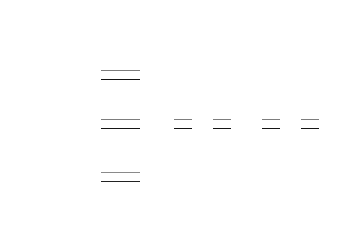
documents and in the Car Pass 3.
Alloy wheels 3, towing equipment 3:
make a note of the key identifier codes.
Electronic immobiliser, Infotainment
system 3: the code numbers are specified
in the Car Pass.
Do not keep the Car Pass in the vehicle.
For key with retractable blade 3, press the
button to extend.
6 Further information – see pages 44, 45,
vehicle recommissioning – see page 190.
To unlock the vehicle and open
the doors:
With key in lock,
turn key towards front of
vehicle or press button q on the
remote control 3,
pull door handle and open door or
sliding door 3.
Unlocking the door from inside:
pull up on lock button.
6 Sliding door 3 – see page 54,
door locks, child safety locks 3 –
see pages 46, 54
electronic immobiliser – see page 45,
radio frequency remote control 3 –
see page 47,
central locking system 3 – see page 51,
Vauxhall alarm system 3 – see page 58.
Page 8
3In brief
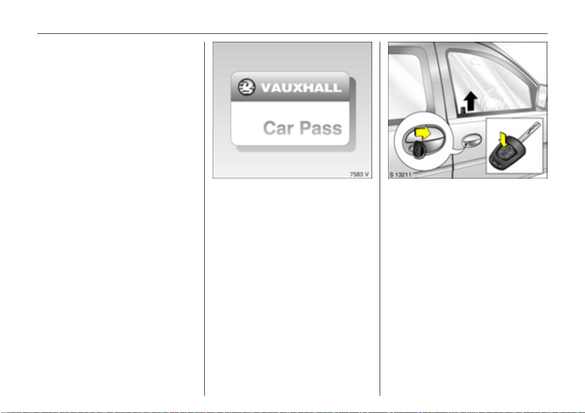
To unlock and open tailgate 3:
Turn key to horizontal position
or press button q on the remote
control 3,
press button and open tailgate
upwards
When using the remote control, the tailgate
is only unlocked if the key slot in the button
is in the horizontal position.
If the key slot is in the vertical position, the
tailgate is always locked.
6 Radio frequency remote control 3 –
see page 47,
central locking system 3 – see page 51,
Vauxhall alarm system 3 – see page 58,
tailgate 3 – see page 55.
To unlock and open rear doors 3:
Turn key to vertical position
or press button q on the remote
control 3,
pull handle and open rear door.
To open the left rear door, pivot
the handle on the inside
When using the remote control, the rear
doors are only unlocked if the key slot in the
lock is in the vertical position.
If the key slot is in the horizontal position,
the rear doors are always locked.
6 Radio frequency remote control 3 –
see page 47,
central locking system 3 – see page 51,
Vauxhall alarm system 3 – see page 58,
rear doors 3 – see page 56.
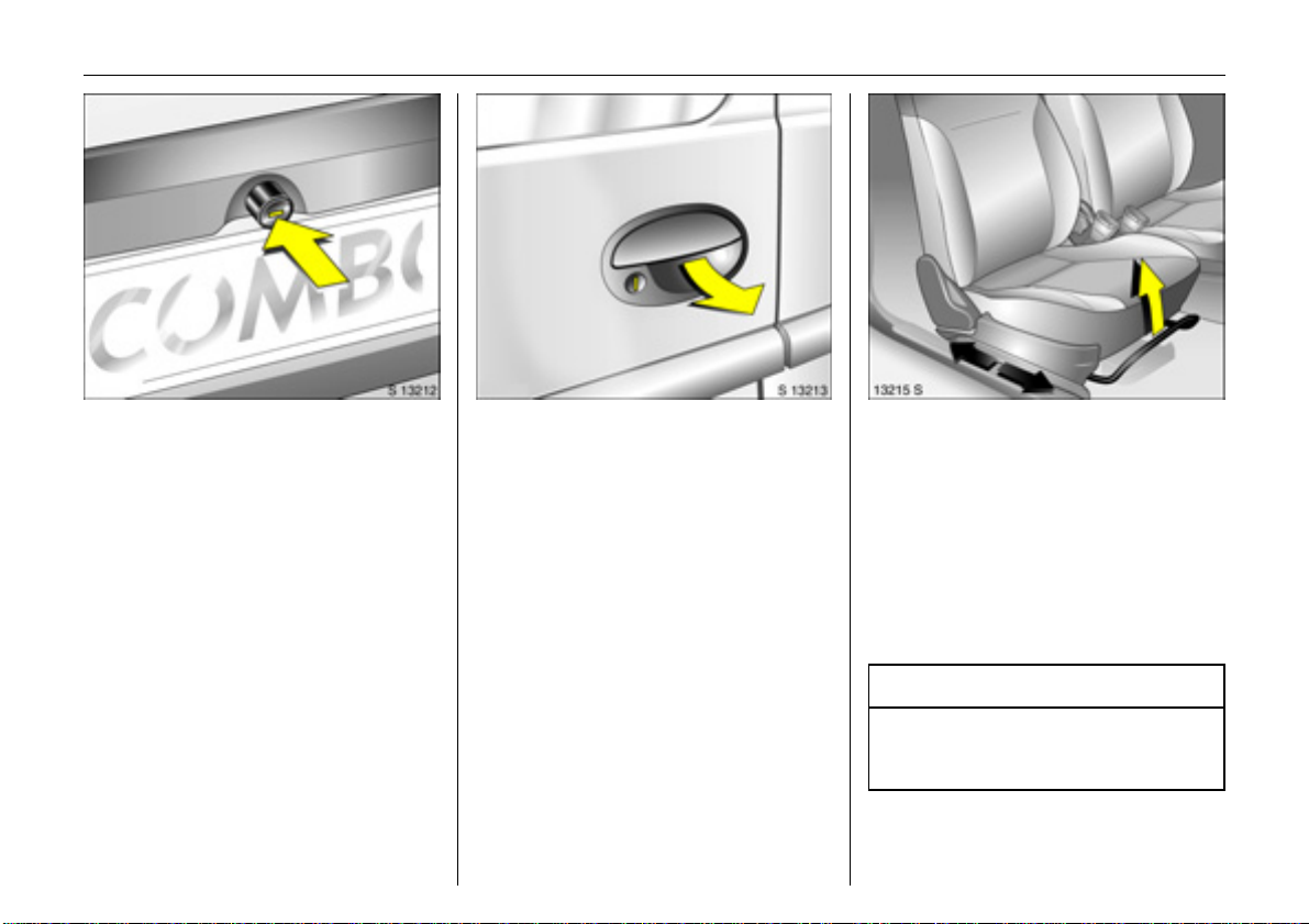
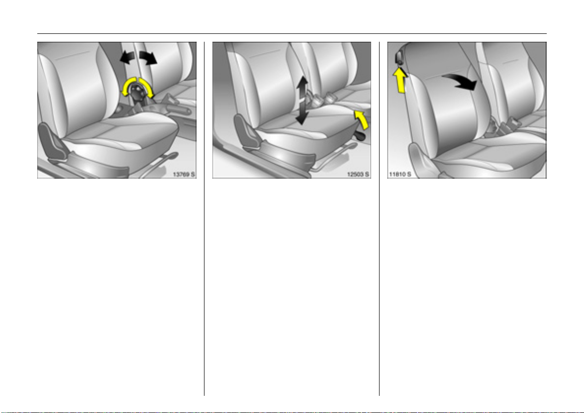
To adjust front seat 3:
Pull handle,
slide seat,
release handle,
allow seat to audibly latch into
position
Never adjust the seat whilst driving. It could
move in an uncontrolled manner when the
handle has been pulled.
6 Seat position – see page 63.
9 Warning
Important: Do not sit nearer than 10
inches (25 cm) from the steering wheel, to
permit safe airbag deployment.
Page 9
4 In brief
To adjust front seat backrests:
Turn handwheel
Move seat backrest to suit seating position.
Do not lean on seat backrest whilst
adjusting it.
6 Seat position – see page 63.
To adjust front seat height 3:
Pull lever at side
Lift lever and relieve some weight from seat
to raise it or press down on seat with body
weight to lower it.
Never adjust the driver’s seat whilst driving.
It could move in an uncontrolled manner
when the lever has been pulled.
6 Seat position – see page 63.
To fold front seat backrest 3:
Raise lever
To enter and leave the rear seat area, tilt
front seat back forwards.
6 Seat position – see page 63.
Page 10
5In brief
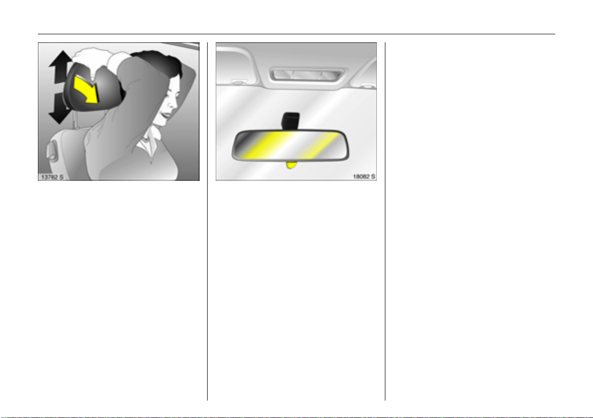
To adjust height 3 of front and
outboard rear head restraints:
Tilt forward to release,
hold and adjust height,
release
6 Head restraint position – see page 63,
further information, removal –
see page 64,
centre rear head restraint 3 – see page 64.
To adjust interior mirror:
Swivel mirror housing
Swivel lever on underside of mirror housing
to reduce dazzle at night.
Page 11
6 In brief
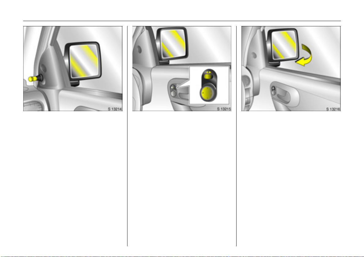
To adjust exterior mirrors:
Swivel lever in required direction
6 Further information, aspherical exterior
mirror 3 – see page 91.
Electrically adjustable
exterior mirrors 3:
Four-way switch in driver’s door
Toggle switch to left or right:
four-way switch moves appropriate mirror.
6 Additional instructions, aspherical
exterior mirror 3 – see page 91,
heated exterior mirror 3 – see page 16.
To retract exterior mirrors
The mirrors retract when subjected to slight
pressure.
Return the mirrors to the driving position
before starting-off.
Page 12
7In brief
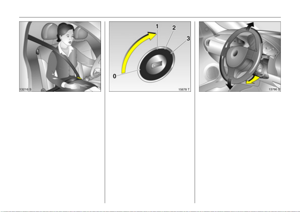
Fitting seat belt:
Draw seat belt smoothly from
inertia reel,
guide over shoulder
and engage in buckle
The belt must not be twisted at any point.
The lap belt must lie snugly against the
body. The backrest must not be tilted back
too far (recommended maximum tilting
angle approx. 25°).
To release belt, press red button on belt
buckle.
6 Safety belts – see pages 76 to 82,
airbag systems 3 – see page 82,
seat position – see page 63.
Releasing steering column lock:
Move the steering wheel slightly
and turn the key to position 1
Positions:
0 = Ignition off
1 = Steering released, ignition off
2 = Ignition on,
Diesel engines: preheating
3=Start
6 Starting – see page 18,
electronic immobiliser – see page 45,
remove key and lock steering wheel –
see page 19.
Steering wheel adjustment 3:
Swivel lever down,
Adjust height,
Swivel lever up,
Engage
Adjust steering wheel only when vehicle is
stationary and steering column lock is
released.
6 Airbag systems 3 – see page 82.
Page 13
8 In brief
Page 14

9In brief
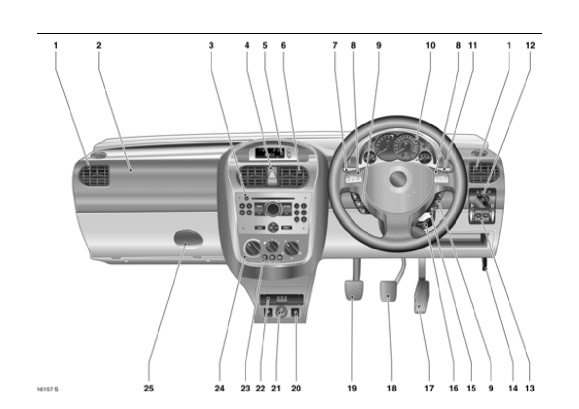
1 Side air vents ................................. 102
Page
2 Front passenger’s airbag 3 ........... 82
3 Infotainment system 3 ................... 42
4 Hazard warning lights .................... 14
LED for
Vauxhall alarm system 3 ................. 58
5 Display 3 for time, date,
outside temperature,
Infotainment system 3 ................... 31
6 Centre air vents .............................. 102
7 Turn signals, headlight flash,
dipped beam, main beam ............. 13
8 Horn .................................................. 14
9 Infotainment system
remote control 3 ............................. 22
10 Instruments ...................................... 24
Page
11 Windscreen wiper,
windscreen wash system,
rear window wash system 3 ........... 15
12 Light switch ................................13, 93
13 Headlight range adjustment ........... 94
fog tail light ...................................... 95
front fog lights 3 .............................. 94
instrument illumination .................... 95
14 Bonnet release lever ........................ 61
15 Starter switch with
steering column lock ......................... 7
16 Steering wheel adjustment 3 ........... 7
17 Accelerator pedal ................. 117, 118
18 Brake pedal ........................... 117, 129
19 Clutch pedal 3 .............................. 118
20 Seat heating 3 .............................. 103
Page
21 Accessory socket or
cigarette lighter 3 .......................... 71
22 Ashtray 3 ......................................... 72
23 Air conditioning system 3 ............ 107
heated rear window 3 ............ 16, 103
air recirculation system 3 ............. 107
24 Heating and ventilation system .. 101
25 Glove compartment ....................... 73
Page 15

10 In brief
Control indicators
X Seat belt warning device 3,
see page 24.
> Front fog lights 3,
see pages 24, 94.
A Engine electronics,
transmission electronics 3,
electronic immobiliser,
diesel fuel filter 3
see pages 24, 45, 126.
Z Exhaust emissions 3,
see pages 25, 45, 125.
v Airbag systems 3,
belt tensioners,
see pages 77, 86.
I Engine oil pressure,
see page 25.
O Turn signal lights,
see pages 14, 25.
C Main beam,
see pages 13, 26.
! Preheating for diesel engines 3,
diesel particle filter 3
see page 26.
T Easytronic Winter programme 3,
see page 113.
r Fog tail light,
see pages 26, 95.
p Alternator,
see page 26.
R Brake system,
clutch system 3,
see page 26.
u Anti-lock Brake System (ABS) 3,
see page 131.
S Engine oil level 3,
see pages 27, 182.
EPS Electric power-assisted steering 3,
see page 27.
Y Fuel level 3,
see pages 27, 30, 143.
Page 16

11In brief
Lighting
Light switch,
switch positions,
see pages 13, 93,
7 Lights off,
8 Parking lights,
9 Dipped beam, main beam.
0 Courtesy light,
see page 96.
C Dipped beam, main beam,
see page 13.
O Turn signal lights,
see page 14.
> Front fog lights 3,
see page 94.
r Fog tail light,
see page 95.
k Instrument illumination,
see page 95.
? Headlight range adjustment,
see page 94.
¨ Hazard warning lights,
see page 14.
Climate control
x Airflow,
see page 104.
Air distribution,
see page 104,
V to windscreen and
front door windows,
J to windscreen, front
door windows
and footwell,
K to footwell,
L to head area and footwell,
M to head area.
Ü Heated rear window 3,
see page 103.
n Air conditioning system 3,
see page 107.
4 Air recirculation system 3,
see page 107.
ß Heated front seats 3,
see page 103.
Page 17

12 In brief
Windscreen wiper
Stalk positions,
see page 15,
§ Off,
$ Timed interval wipe,
% Slow,
& Fast.
Date, time, information display,
Infotainment system
Information display 3,
see page 31.
Ö On button for date
and time,
; Setting buttons for date and time.
Infotainment system
remote control 3,
see page 22.
Miscellaneous
p Central locking system 3,
locking – see page 51.
q Central locking system 3,
unlocking – see page 51.
j Horn,
see page 14.
T Easytronic Winter programme 3,
see page 113.
+ First-aid kit (cushion) 3,
see page 148.
¨ Warning triangle 3,
see page 148.
Page 18
13In brief
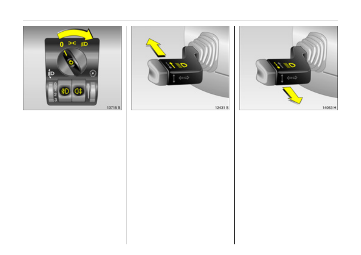
Light switch:
7 = Off
8 =Parking lights
9 = Dipped or
main beam
0 Push = Courtesy light
> Push = Front fog lights 3
r Push = Fog tail light
6 Further information – see page 93,
headlight warning device – see page 20,
headlight range adjustment –
see page 94,
daytime running lights 3 – see page 93.
Main and dipped beam switch:
Main beam = Push stalk
forward
Dipped beam = Push stalk
forward again
The blue control indicator C is illuminated
when main beam is on.
Headlight flash:
Pull stalk towards steering wheel
Page 19
14 In brief
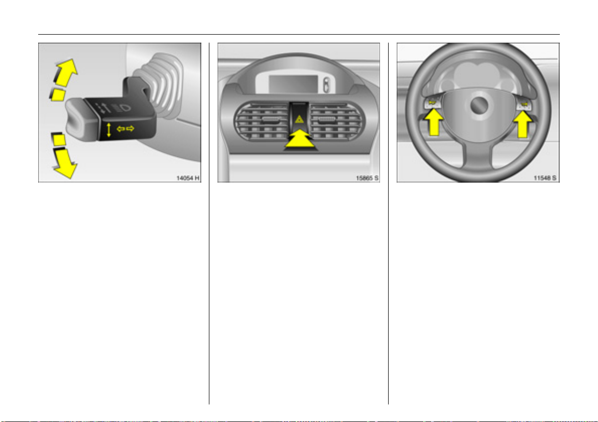
Operating turn signal lights:
Stalk in rest position
Right = Up
Left = Down
When the steering wheel is turned back, the
stalk automatically returns to its original
position. This will not happen when making
a minor steering manoeuvre such as
changing lane.
When lane changing, move stalk to
resistance point. When released, the stalk
will spring back.
Hazard warning lights:
On = Press ¨
Off = Press ¨ again
To aid location of the pushbutton, the red
surface is illuminated when the ignition is
switched on. When the button is pressed,
its control indicator flashes in time with the
hazard warning lights.
Horn operation:
Press j
6 Airbag systems 3 – see page 82,
remote control for Infotainment system 3 -
see page 22.
Page 20
15In brief
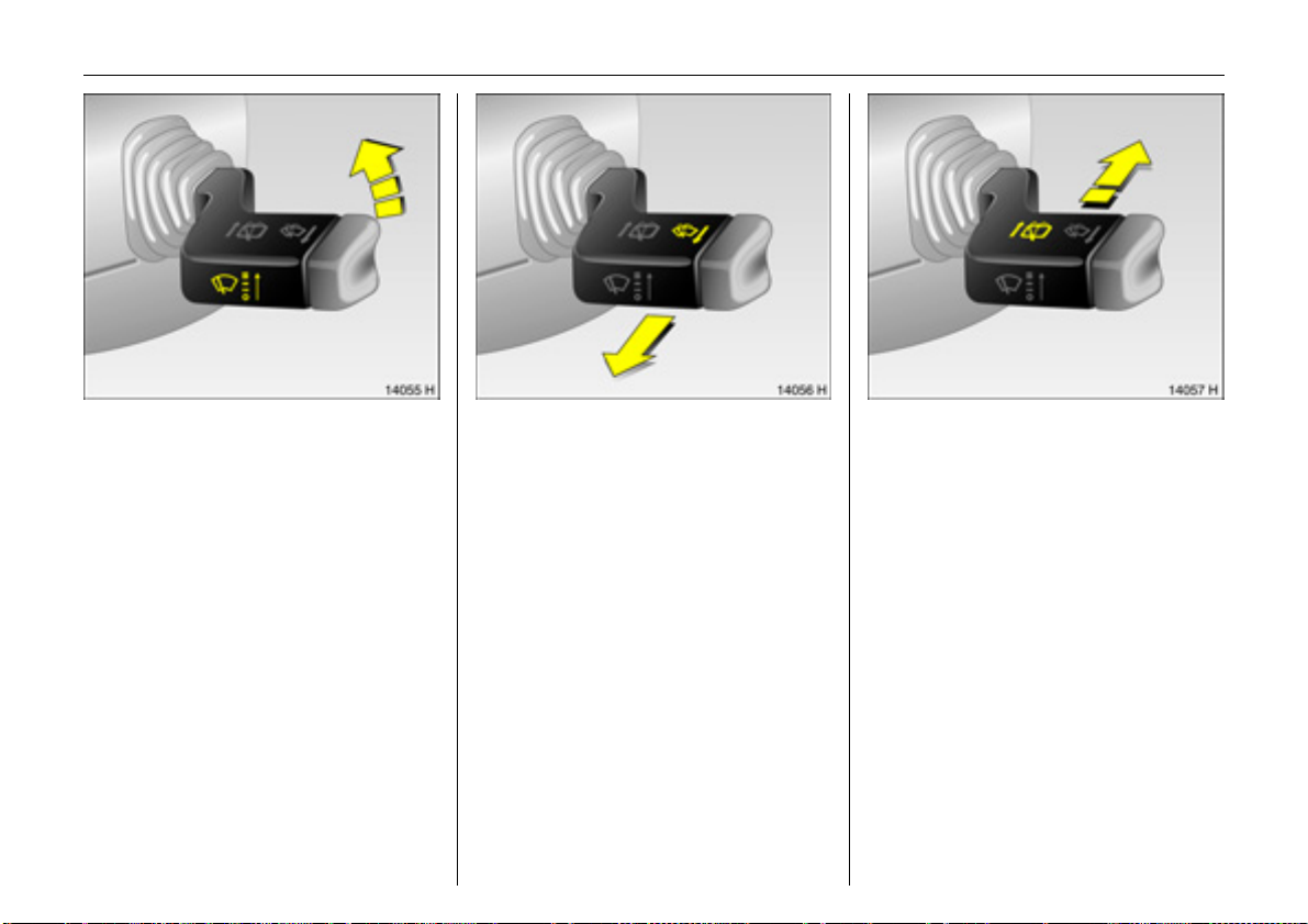
Windscreen wiper:
Move stalk upwards
§ = Off
$ = Adjustable timed interval
% = Slow
& = Fast
Setting wiper interval to a value between 2
and 15 seconds:
move stalk to interval switching $,
move stalk to §,
wait for desired interval time,
move stalk back to interval switching $.
The interval remains stored until the next
change or until the ignition is switched off.
Switching the ignition on and moving the
stalk to $ sets the interval to 7 seconds.
Operating windscreen wash
system:
Pull stalk towards steering wheel
The wiper will swipe for a few strokes.
6 Further information –
see pages 188, 194.
Operating rear window wiper 3
and wash systems 3:
Wiper on = Push stalk forward
Wiper off = Pull stalk towards
steering wheel
Wash = Push stalk forward
and hold
The rear window wiper swipes in timed
interval mode.
The wiper will swipe for a few strokes when
washing.
6 Further information –
see pages 188, 194.
Page 21
16 In brief
Heated rear window 3,
heated exterior mirrors 3:
On = Press Ü
Off = Press Ü again
Rear window and exterior mirror heating is
only operational with ignition switched on.
Control indicator in switch.
6 Further information – see page 103.
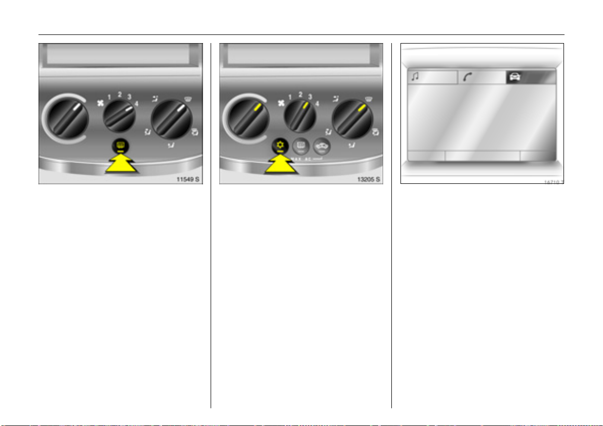
Clearing misted or icy windows:
Turn rotary knobs for
temperature and airflow
clockwise,
set air distribution to V,
press air conditioning switch n 3
Close centre air vents; push sliders inwards.
Direct side air vents towards door windows.
6 Climate control – see page 101,
air conditioning 3 – see page 107.
Range
Inst. consumpt.
19,5° 19:36
257
31
miles
mpg
Information display 3
Provides information on the following:
–Time,
– Outside temperature,
–Radio3 or date,
– Navigation 3,
– Telephone 3,
–Trip computer3.
6 Information display – see page 31.
Page 22
17In brief
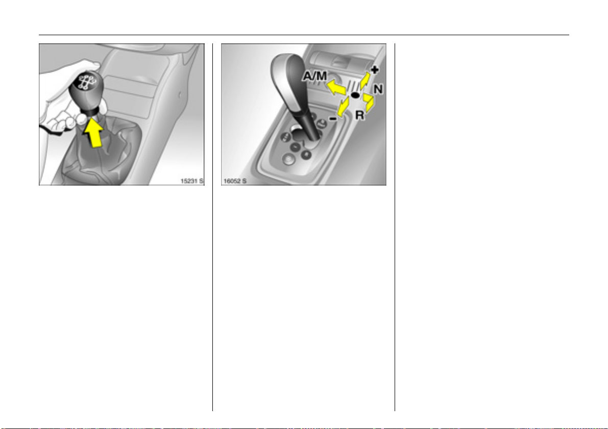
Manual transmission:
Reverse gear: with vehicle stationary,
pull the ring up three seconds after
depressing clutch pedal and engage gear.
If the gear does not engage, set the lever in
neutral, release the clutch pedal and
depress again; then repeat gear selection.
Easytronic 3:
N = Neutral / start position
o =Driving position
(centre position)
+ =Higher gear
- = Lower gear
A/M = Switch between
Automatic and
Manual mode
R = Reverse
(with selector lever lock)
To move the selector lever from N to R,
press the button on the lever.
Only start in N with footbrake applied.
6 Further information – see page 113.
Page 23
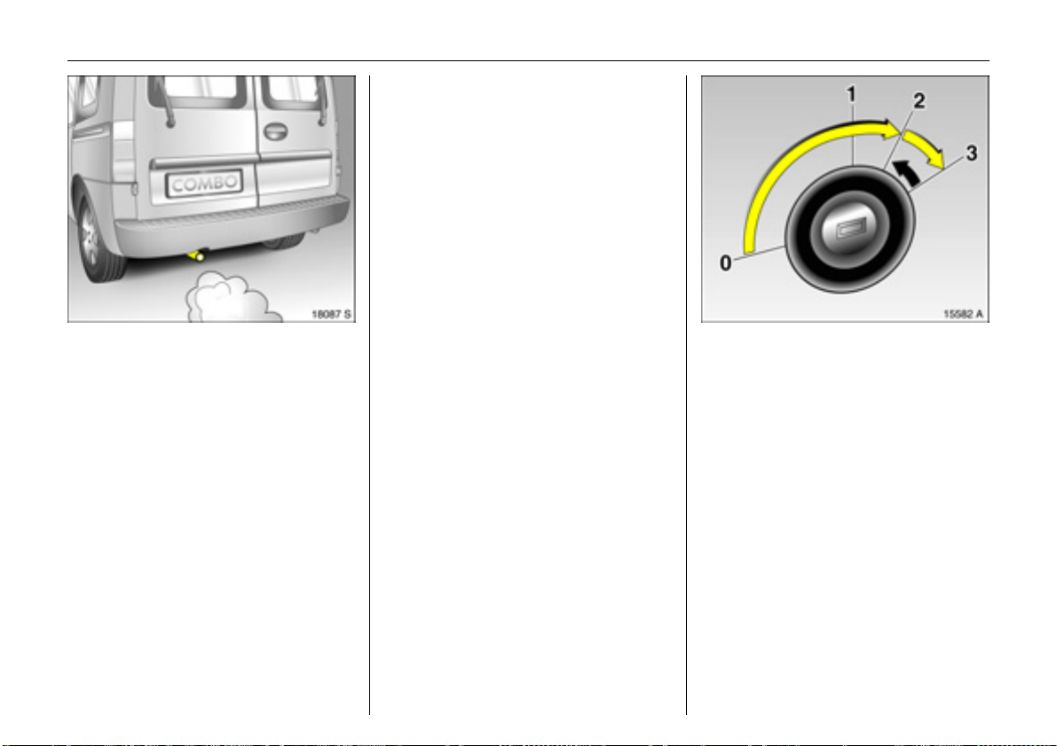
18 In brief
Exhaust gases are poisonous
Exhaust gases contain carbon monoxide,
which is extremely poisonous but is
odourless and colourless.
Therefore never inhale exhaust gases, and
never run the engine in an enclosed space.
Avoid driving with an open load
compartment. Otherwise, exhaust gases
could penetrate the interior.
Before starting-off, check:
z Tyre pressure and tyre condition -
see pages 134, 205.
z Engine oil level and fluid levels in engine
compartment – see pages 181 to 188.
z All windows, mirrors, exterior lighting
and number plates are free from dirt,
snow and ice and are operational.
z No objects are placed in front of the rear
window, on the instrument panel or in
the area in which the airbags inflate.
z Seats, seat belts and mirrors are
correctly adjusted.
z Brake operation.
To start the engine:
Depress clutch and brake pedals,
Easytronic 3 in N,
do not accelerate,
petrol engine: key to position 3;
diesel engine: key to position 2,
when control indicator !
goes out1), turn key to position 3;
release key once engine is
running
To repeat the start procedure or switch off
the engine, turn the key back to position 0.
To switch on the ignition, turn the key
to position 2.
6 Electronic immobiliser – see page 45,
further information – see pages 118, 143.
1)
Preheating system switches on only if outside
temperature is low.
Page 24
Warning buzzers
When starting the engine or whilst driving:
z if seat belt is not fastened 3,
z if a specified maximum speed is
exceeded 3.
When parking the vehicle and opening the
driver’s door:
z when the ignition key is in the starter
switch,
z if parking lights / dipped beam are on,
z if the turn signal stalk is engaged.
19In brief
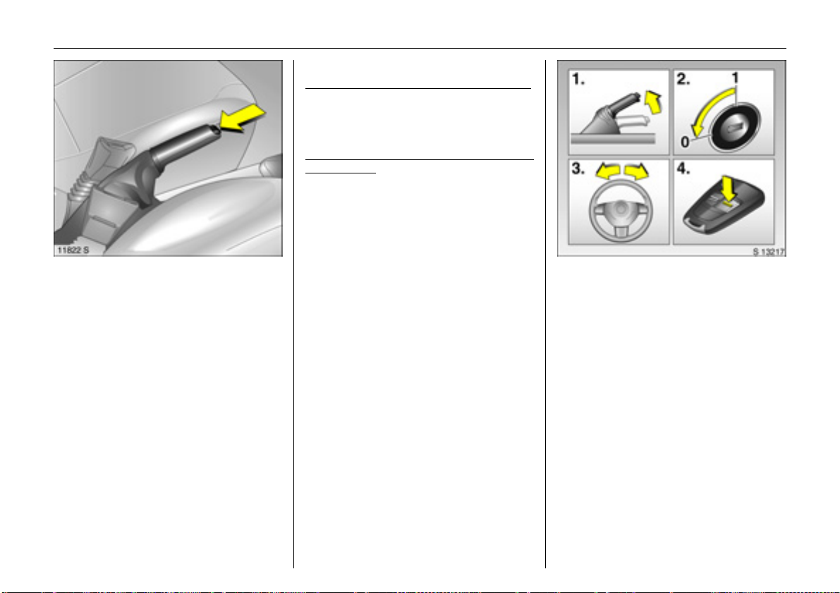
To release the handbrake:
Raise lever slightly,
press lock button,
lower lever fully
In order to reduce the operational forces,
depress the footbrake at the same time.
Drive carefully, economically and with the
environment in mind. Whilst driving, do not
do anything that could distract you.
6 Brakes - see page 128.
Parking the vehicle:
Apply handbrake firmly,
turn engine off andremove key,
lock steering wheel,
lock doors
To lock, turn the key in the lock of any
unlocked door towards the rear of the
vehicle or press button p on the remote
control. Lock load compartment.
To arm the Vauxhall alarm system 3, press
button p once and to activate the
mechanical anti-theft locking system,
press button p twice.
6 Further information – see pages 45, 117,
radio frequency remote control 3 –
see page 47,
central locking system 3 – see page 51,
Vauxhall alarm system 3 – see page 58,
vehicle decommissioning – see page 190.
Page 25
20 In brief
Advice when parking:
z Always apply handbrake firmly.
On slopes apply the handbrake as firmly
as possible.
z With manual transmission, select first
gear or reverse gear, with Easytronic 3
move selector lever to centre position
before switching ignition off.
z Close the windows.
z O n vehi cles with Ea syt ronic 3 the control
indicator R flashes for a few seconds
after the ignition is switched off, if the
handbrake has not been applied.
z Turn steering wheel until lock is felt to
engage (anti-theft protection).
z Engine cooling fan may run on after the
engine has been switched off.
z Do not park vehicle on easily ignitable
surfaces as the hot exhaust system
temperatures could cause the surface to
ignite.
6 Further information – see pages 188, 190.
Service work,
Maintenance
We recommend that you entrust all work to
your Vauxhall Authorised Repairer, who
can provide you with reliable service and
correctly perform all work according to
factory instructions.
6 If you have a problem – see page 178,
service interval display – see page 180.
Page 26

21In brief
Genuine Vauxhall Parts and
Accessories
We recommend that you use "Genuine
Vauxhall Parts and Accessories" and
conversion parts approved expressly for
your vehicle type. These parts have
undergone special tests to establish their
reliability, safety and specific suitability for
Vauxhall vehicles. Despite continuous
market monitoring, we cannot assess or
guarantee these attributes for other
products, even if they have been granted
approval by the relevant authorities or in
some other form.
"Genuine Vauxhall Parts and Accessories"
and conversion parts approved by
Vauxhall can be obtained from your
Vauxhall Authorised Repairer, who can
provide comprehensive advice on
permitted technical changes and ensure
correct installation.
9 Warning
Carry out regularly the checks
recommended in the individual sections
of this Owner’s Manual.
Ensure that your vehicle is serviced as
indicated by the service interval display.
We recommend that you consult your
Vauxhall Authorised Repairer.
Have faults remedied without delay!
Consult a workshop. We recommend your
Vauxhall Authorised Repairer. If
necessary, interrupt your journey.
6 Maintenance – see page 180.
That was a brief overview of
the most important information
for your first drive in your Combo.
The other pages of this chapter
contain a description of some
interesting functions in your
vehicle.
The remaining chapters of the
Owner’s Manual contain
important information on
operation, safety and
maintenance as well as a
complete index.
Page 27
22 In brief
Ü Board Computer 19,5° 19:36
BC 1 All values
BC 2
Timer
257.0 miles
Ø40mph
31.0 mpg
Ø 7.0 gals
Operating the Infotainment
system via the information
display menus
The menu options are selected via the
menus and with the button / four-way
button or the multi-function button of the
Infotainment system 3 or via the buttons 3
on the steering wheel. The menu options
appear on the information display.
To select with four-way button:
press four-way button up, down, left or
right.
To select with the multi-function button
(rotary knob over the four-way button,
see page 34):
press and turn multi-function button.
To exit a menu, turn the multi-function
button left or right to Return or Main and
select.
To select with steering wheel buttons:
select menu options via the menus using
the buttons.
For further information, see Infotainment
system instructions.
Trip computer 3
The trip computer shows vehicle data that
is continually recorded and evaluated
electronically.
Functions:
z Range
z Instantaneous consumption
z Distance travelled
z Average speed
z Average consumption
z Effective consumption
z Stop watch
Page 28
23In brief
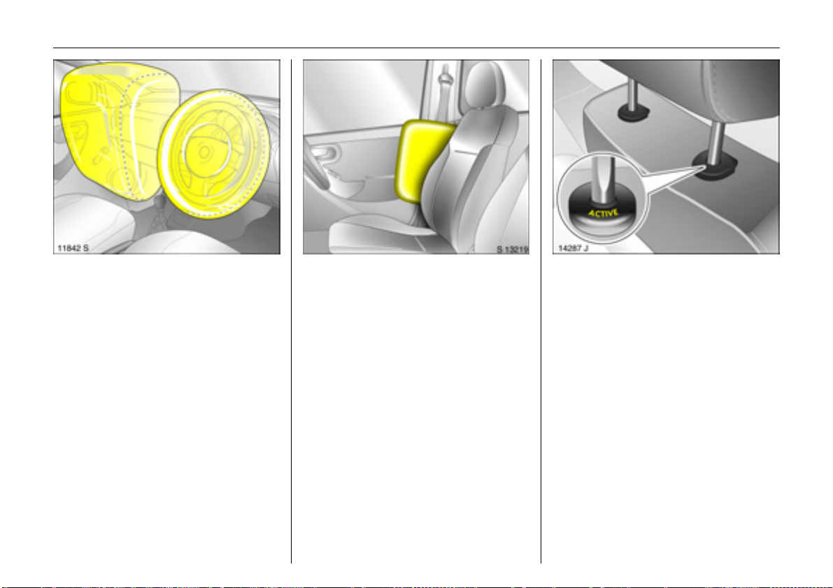
Vauxhall Full-size airbag system
The Vauxhall Full-size airbag system
comprises several individual systems.
Front airbag system 3
The front airbag system will be triggered in
the event of a serious accident involving a
frontal impact and forms safety cushions
for the driver and front passenger. The
forward movement of the driver and front
passenger is checked and the risk of
injuries to the upper body and head
thereby substantially reduced.
Side airbag system 3
The side airbag system triggers when a
side-on collision occurs and provides a
safety barrier for the driver and/or
passenger in the respective front door
area. This reduces the risk of injury to the
upper body considerably in the event of a
side-impact.
6 Further information – see page 82.
Active head restraints 3
In the event of a rear-end impact, the
active head restraints automatically tilt
forward a little. The head is more
effectively supported by the head restraint
and the danger of injuries caused by
whiplash in the neck area is reduced.
Active head restraints are identified by the
lettering ACTIVE on the head restraint
guide bushes.
Page 29
24 Instruments
Instruments
Control indicators ................................ 24
Instrument display............................... 28
Information display ............................. 31
Radio reception 3................................ 42
Infotainment system 3........................ 42
Remote control buttons 3 for
Infotainment system 3 and
information display........................... 42
Mobile telephones and radio
equipment (CB) 3 ............................. 43
Control indicators
Picture no: 18122s.tif
The control indicators described here are
not present in all vehicles. The descriptions
however, apply to all instrument versions.
X
Seat belt warning device 3
If the control indicator illuminates after
the ignition is switched on (with warning
buzzer), fasten seat belt - see page 79.
>
Front fog lights 3
The control indicator is illuminated when
the front fog lights are on - see page 94.
A
Picture no:
Engine electronics,
transmission electronics 3,
electronic immobiliser, diesel fuel filter 3
The control indicator illuminates for a few
seconds when the ignition is switched on.
If it illuminates when the engine is running
Fault in engine electronics or transmission
electronics. Electronics switch to emergency
running programme, fuel consumption
may increase and driveability of the vehicle
may be impaired - see page 126. Consult a
workshop immediately. We recommend
your Vauxhall Authorised Repairer.
If it flashes when the ignition is on
Fault in the electronic immobiliser system;
the engine cannot be started –
see page 45.
:
:
Page 30
Z
Picture no: 18121s.tif
Exhaust emissions
The control indicator illuminates when the
ignition is switched on and goes out shortly
after the engine starts.
If it illuminates when the engine is running
Fault in emission control system.
The permitted emission limits may be
exceeded. Consult a workshop. We
recommend your Vauxhall Authorised
Repairer.
If it flashes when the engine is running
Fault that can lead to destruction of the
catalytic converter is indicated see page 125. Consult a workshop
immediately. We recommend your
Vauxhall Authorised Repairer.
:
v
Picture no:
Airbag systems 3,
belt tensioners
see pages 78, 86.
I
:
Engine oil pressure
The control indicator illuminates when the
ignition is switched on and goes out shortly
after the engine starts.
If it illuminates when the engine is running
Engine lubrication may be interrupted. This
may result in damage to the engine and/or
locking of the drive wheels:
1. Move out of the flow of traffic as quickly
as possible without impeding other
vehicles.
2. Depress clutch 3.
3. Move gearshift lever to neutral, or with
Easytronic 3 place selector lever in N.
4. Switch off ignition.
9 Warning
When the engine is off, considerably
more force is needed to brake and steer.
Do not remove key until vehicle has come
to a standstill, otherwise the steering
column lock could engage unexpectedly.
Check oil level before consulting a
workshop. We recommend your Vauxhall
Authorised Repairer.
O
Turn signal lights
When the turn signal is activated, the
corresponding control indicator flashes.
Rapid flash: A turn signal bulb is faulty.
:
Both control indicators flash when the
hazard warning lights are activated.
Bulb replacement - see page 167.
25Instruments
Page 31

26 Instruments
C
Main beam
The control indicator is illuminated when
main beam is on and during headlight
flash - see page 93.
!
Preheating for diesel engines 3,
diesel particle filter 3
Control indicator illuminates during
preheating.
Preheating system switches on only if
outside temperature is low.
Flashing (vehicles with diesel particle filter):
The diesel particle filter must be cleaned.
As soon as the road surface and traffic
situation permits, briefly increase speed
over 25 mph (40 km/h). The control
indicator goes out as soon as cleaning is
complete.
T
Easytronic Winter programme 3
Control indicator is illuminated when
Winter programme is enabled.
Further information – see page 113.
r
Fog tail light
The control indicator is illuminated when
the fog tail light is on - see page 95.
p
Picture no: 18122s.tif
Alternator
The control indicator illuminates when the
ignition is switched on and goes out shortly
after the engine starts.
If it illuminates when the engine is running
Stop the vehicle and switch off the engine.
The battery is not being charged. Engine
cooling may be interrupted. Check drive
belt condition and tensioning before
contacting a workshop. We recommend
your Vauxhall Authorised Repairer.
R
Picture no:
Brake system,
clutch system 3
The control indicator illuminates when the
ignition is switched on if the handbrake is
applied or if the brake or clutch fluid level 3
:
is too low. Further information see pages 130, 186.
9 Warning
If it illuminates when the handbrake is not
applied: stop the vehicle; interrupt your
journey immediately. Consult a
workshop. We recommend your Vauxhall
Authorised Repairer.
On vehicles with Easytronic 3, control
indicator R flashes for a few seconds after
the ignition is switched off if the handbrake
has not been applied.
Page 32

27Instruments
u
Anti-lock Brake System (ABS) 3
see page 131.
S
Engine oil level 3
Illuminated: low engine oil level. Check oil
level and top up as necessary –
see page 182.
1)
EPS
Electric power-assisted steering 3
The control indicator illuminates for a few
seconds when the ignition is switched on.
Illumination whilst driving indicates a fault.
Driving may be continued. More force is
required for steering. Consult a workshop.
We recommend your Vauxhall Authorised
Repairer.
Y
Fuel level 3
Illuminated: low fuel level. Fuel gauge in
reserve area.
Flashing: fuel supply used up, fill tank
immediately.
Never let the tank run dry!
Erratic fuel supply can cause catalytic
converter to overheat – see page 124.
Diesel engines: if the tank is run dry, bleed
the fuel system as described on page 143.
Picture no: 12478s.tif
Transmission display 3
Display of current gear or mode with
Easytronic 3.
Further information – see pages 111.
1)
EPS = Electric Power-assisted Steering.
Page 33

28 Instruments
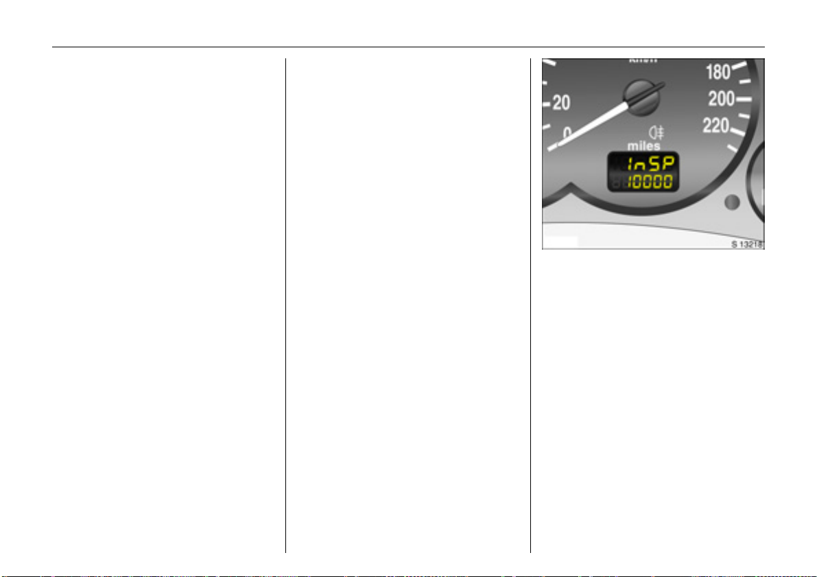
Trip odometer
To return to zero, depress reset knob with
ignition switched on and trip odometer
display activated.
Vehicles with clock in odometer
To set to zero, hold reset knob down for
approx. 2 seconds with ignition switched
on and trip odometer activated.
To switch between trip odometer and time
display 3: give reset knob a short press –
see next page.
Service interval display - see page 180.
:
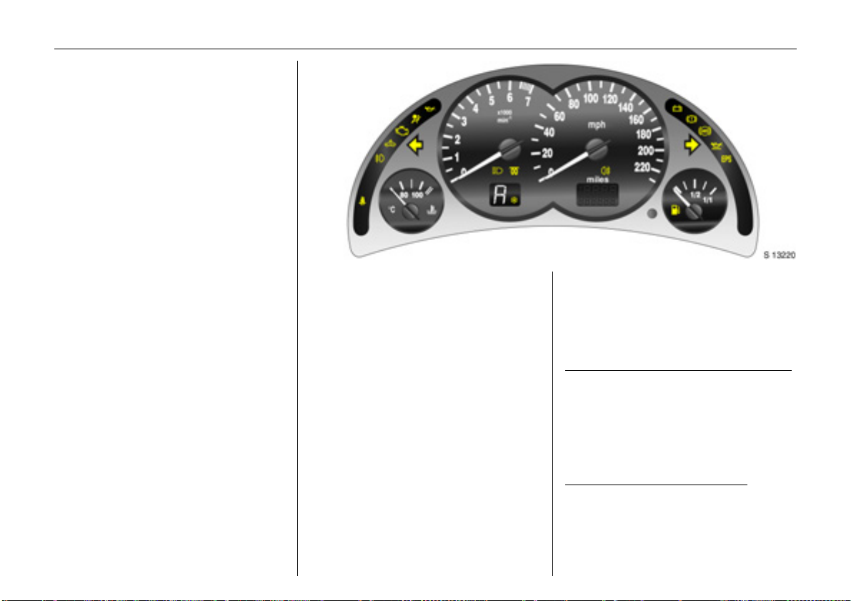
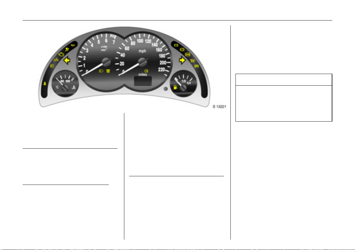
Instrument display
Picture no: 12098s.tif.
Tachometer
Indicates engine speed.
Warning zone: maximum permissible
engine speed exceeded; danger to engine.
Speedometer
Picture no:
Indicates the vehicle speed.
Odometer
Records the miles / kilometres driven.
With the ignition switched off, briefly press
the reset knob to display the number of
miles / kilometres driven for approx. 15
seconds.
Page 34

Setting the time
With time displayed, press reset knob in
instrument panel:
Press for approx. 2 seconds:
Hours flash
Press briefly
Set hours
Press for approx. 2 seconds
Minutes flash
Press briefly
Set minutes
Press for approx. 2 seconds
Clock is started.
29Instruments
Time display in odometer 3
Picture no: 12099s.tif.
To switch between trip odometer and time
display 3 give reset knob a short press.
When the vehicle lights are on, the
brightness of the display can be adjusted
using the right-hand adjuster wheel k
below the light switch – see page 96.
Page 35

30 Instruments
For physical reasons, the engine
temperature gauge shows the coolant
temperature only if the coolant level is
adequate.
During operation the system is pressurised.
The temperature may therefore rise briefly
to over 100 °C.
Coolant temperature display
Picture no: 11688s.tif
Pointer in left
zone = Engine operating
Pointer between
the zones = Normal operating
Pointer in
right zone
(warning zone)
temperature not yet
reached
temperature
= Temperature too
high:
stop vehicle and
switch off engine.
Danger to engine.
Check coolant level
immediately –
see page 185.
Picture no: 11689s.tif
Fuel gauge
Pointer in red
warning zone or Y
illuminated = Reserve level
Pointer in red
warning zone or Y
flashing = Refuel immediately
Never run the tank dry!
Diesel engines: if the tank is allowed to run
dry, bleed the fuel system as described on
page 143.
Because of the fuel remaining in the tank,
the amount of fuel required to fill the tank
may be less than the specified tank
capacity.
- see page 122.
Page 36

12:01 17,0°C
Range
257
miles
31Instruments
Infotainment system – see Infotainment
system operating instructions.
An F in the display indicates a fault. Have
the cause of the fault remedied. We
recommend that you consult your Vauxhall
Authorised Repairer.
FM 3 90,6MHz
REG AS RDS TP
Picture no: 17913s.tif
Information display
Triple Information Display 3
Display of time, outside temperature and
date / Infotainment system (when it is on).
When the ignition is off, the time, date and
outside temperature can be made to
appear for approx. 15 seconds by briefly
pressing one of the two buttons adjacent
to the information display.
An F in the display indicates a fault. Have
the cause of the fault remedied. We
recommend that you consult your Vauxhall
Authorised Repairer.
31
Inst. consumpt.
19,5° 19:36
mpg
Picture no: 16710t.tif
Graphical Information Display 3
Display of time, outside temperature and
date / Infotainment system (when it is on).
The information that is displayed depends
on the Infotainment system configuration.
Some information appears in an
abbreviated form.
Page 37

32 Instruments
8:56 -5,5°C
07.04.2004
9 Warning
Caution: the road surface may already
be icy even though the display indicates
:
Slippery road
-2,5°C
OK
a few degrees above 0 °C.
Outside temperature
Picture no: 17913s.tif
A fall in temperature is indicated
immediately and a rise in temperature
after a time delay.
If outside temperature drops below 3 °C,
the symbol : appears in the Triple
Information Display as a warning for icy
road conditions. When temperature
increases to at least 5 °C, the : symbol
goes out.
In vehicles with Graphical Information
Picture no: 16707t.tif
Display 3, a warning message is shown in
the display as a warning for icy road
surfaces. There is no message below -5 °C.
Page 38

33Instruments
8:56 5,5°C
07.04.2004
Picture no: 17914s.tif
Triple Information Display
Setting date and time
Infotainment system off. Press Ö and ;
next to the display as follows:
Press Ö for approx. 2 seconds:
Day flashes
;:Set day
Ö:Month flashes
;:Set month
Ö:Year flashes
;:Set year
Ö:Hours flash
;: Set hours
Ö:Minutes flash
;:Set minutes
Ö:Clock is started.
Correcting time
Some RDS transmitters do not send a
correct time signal. If the incorrect time is
continually displayed, switch off automatic
time synchronisation 3 and set the time
manually - see next column.
The automatic setting is indicated by } in
the display.
3:
Activating and deactivating automatic
time synchronisation: Infotainment system
off; press Ö and ; next to the display as
follows:
Hold down Ö for approx. 2 sec., clock
display is now in setting mode,
Press Ö twice (until year flashes).
Press Ö and hold down for approx.
3 seconds until } flashes in display 3
and text "RDS TIME" appears
(years flash during this time),
Press ; - display shows:
RDS TIME 0 = Off
Press ; - display shows:
RDS TIME 1 = On
Press Ö three times.
Page 39

34 Instruments
Range
Inst. consumpt.
19,5° 19:36
257
31
miles
mpg
Picture no: 16710t.tif
Graphical Information Display 3
Selecting functions
The Graphical Information Display depicts
functions and their menus.
Functions are selected and executed in the
menu on the display using the four-way
button, the multi-function button 3 on the
Infotainment system or the buttons 3 on
the steering wheel.
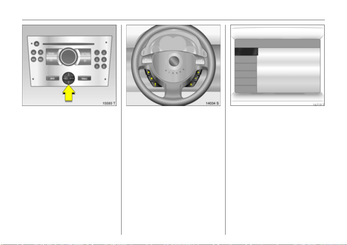
To select with four-way button:
Picture no: 15593t.tif
select menu items via menus and with the
buttons / four-way button of the
Infotainment system.
To select with multi-function button 3:
Picture no: 15559t.tif
Turn Highlight menu items
or commands, select
functions,
Press Select highlighted item,
confirm command.
To exit a menu, turn the multi-function
button left or right to Return or Main and
select.
Page 40

FM AS [TP] REG CDin MP3
90.6
MHz
19,5° 19:36
35Instruments
7 Settings 19,5° 19:36
Time, Date 19:36
Language
Units 10 . 07 . 2004
Contrast
Day / Night
6 Ign. logic
To select with steering wheel buttons 3:
Picture no: 14034s.tif
select menu options via the menus using
the buttons.
Each function has a main page, which is
Picture no: 16711t.tif
selected from the upper row of the display
(not in Infotainment system CD 30):
z Audio
z Navigation 3
z Telephone 3
z Trip computer 3.
For audio, navigation 3 and telephone
functions 3, see Infotainment system
instructions.
System settings
Picture no: 16712t.tif
The settings are accessed via the Settings
menu.
Press the Main button 3 (not found on all
Infotainment systems) on the Infotainment
system (call up main display).
Press the Settings button on the
Infotainment system. For Infotainment
system CD 30, no menu may be selected.
The Settings menu opens.
Page 41

36 Instruments
7 Time, Date 19,5° 19:36
Time 19:36
Date 10 . 07 . 2004
6 Synchron. clock automatical.
Picture no: 16713t.tif
Setting date and time
Select menu item Time, Date from the
Settings menu.
The menu for Time, Date is displayed.
Select the menu items required:
make the desired setting.
Correcting time
Some RDS transmitters
3:
1)
do not send
correct time signals. If the incorrect time is
displayed often, deactivate automatic
time synchronisation 3 and set the time
manually.
To correct time using RDS, select menu
item Synchron. clock automatical. from
the Time, Date menu.
The box in front of Synchron. clock
automatical. will be ticked see Fig. 16713 T.
7 Settings 19,5° 19:36
Time, Date
Language Deutsch
Units English
Contrast Español
Day / Night ...
6 Ign. logic
Picture no: 16714t.tif
Language selection
You can select the display language for
some functions.
Select menu item Language from the
Settings menu.
The available languages are displayed.
1)
RDS = Radio Data System.
Page 42

37Instruments
7 13 Languages 19,5° 19:36
X Deutsch
English
Español
Dutch
French
Italiano
Picture no: 16715t.tif
Select the desired language.
Selections are indicated by a 6 in front of
the menu item.
In systems with language version 3, when
the language setting of the display is
changed, the system will ask if the message
language should also be changed see Infotainment system instructions.
7 Settings 19,5° 19:36
Time, Date
Language
Units
Contrast
Day / Night
6 Ign. logic
~ Europe-SI
| Japan
| Great Britain
| USA
Picture no: 16716t.tif
Setting units of measure
You can select which units of measure are
to be used.
Select menu item Units from the Settings
menu.
The available units are displayed.
Select the desired unit.
Selections are indicated by a o in front of
the menu item.
7 Contrast 19,5° 19:36
12
Picture no: 16717t.tif
Adjust contrast 3
Select menu item Contrast from the
Settings menu.
The menu for Contrast is displayed.
Confirm the required setting.
Page 43

38 Instruments
Setting display mode 3
The display can be adapted to light
conditions: black text on a light
background or white text on a dark
background.
Select menu item Day / Night from the
Settings menu.
The options are displayed.
Automatic: Adapted based on vehicle
lighting.
Always day design: Black text on light
background.
Always night design: White text on dark
background.
Selections are indicated by a o in front of
the menu item.
Ign. logic 3
See Infotainment system instructions.
Ü Board Computer 19,5° 19:36
BC 1 All values
BC 2
Timer
257.0 miles
Ø40mph
31.0 mpg
Ø 7.0 gals
Picture no: 16719t.tif
Graphical Information Display
Trip computer 3
The trip computers provide information on
driving data, which is continually recorded
and evaluated electronically.
The trip computer main page provides
information on range and instantaneous
consumption.
To display the driving data of the other trip
computer, press the BC button on the
Infotainment system 3 or select the trip
computer menu from the display.
On vehicles with Infotainment system
CD 30 3 and steering wheel remote control
buttons 3, the left buttons on the steering
wheel only operate the trip computer.
Range
Inst. consumpt.
19,5° 19:36
257
31
miles
mpg
Picture no: 16710t.tif
Range
Range is calculated from current fuel tank
content and instantaneous consumption.
The display shows average values.
The vehicle updates the range
automatically after a brief delay when the
vehicle has been refuelled.
Page 44

Range
23miles
OK
Picture no: 16718t.tif
If the fuel in the tank will allow less than
30 miles (50 km), the warning "Range"
appears on the display.
Acknowledge the menu item as described
on page 34.
Instantaneous consumption
Display changes depending on speed:
Display in gal/h below 8 mph (13 km/h),
Display in mpg above 8 mph (13 km/h).
Distance travelled
Display of miles / kilometres travelled.
The measurement can be restarted at any
time.
Average speed
Calculation of average speed.
The measurement can be restarted at any
time.
Stoppages in the journey with the ignition
off are not included in the calculations.
Average consumption
Calculation of average consumption.
The measurement can be restarted at any
time.
Effective consumption
Display of amount of fuel consumed.
The measurement can be restarted at any
time.
39Instruments
Ü Board Computer 19,5° 19:36
BC 1 All values
BC 2
Timer
1
8
Resetting trip computer
information (Reset)
The following trip computer information
can be reset (restart measurements):
z Distance travelled
z Average speed
z Effective consumption
z Average consumption
Select BC 1 or BC 2 from the trip computer
menu.
Picture no: 16719t.tif
257.0 miles
Ø40mph
31.0 mpg
Ø 7.0 gals
Page 45

40 Instruments
Ü Reset BC 1 19,5° 19:36
All values
Ü Reset BC 1 19,5° 19:36
All values
Interruption of power supply
If the power supply has been interrupted or
if the battery voltage has dropped too low,
the values stored in the trip computer will
be lost.
257.0 miles
Ø40mph
31.0 mpg
Ø 7.0 gals
Picture no: 16720t.tif
The information of the two trip computers
can be reset separately, thus making it
possible to evaluate data over different
periods of time.
Select the desired trip computer
information.
The value for the selected function will be
reset and recalculated.
257.0 miles
Ø40mph
31.0 mpg
Ø 7.0 gals
Picture no: 16721t.tif
To reset all information of a trip computer,
select menu item All values.
After resetting, "- - -" is displayed with the
trip computer information selected. The
recalculated values are displayed after a
brief delay.
Page 46

Ü Board Computer 19,5° 19:36
BC 1
BC 2
Timer
00:00:00
Start
Reset
Options
Picture no: 16722t.tif
Stop watch
Select menu item Timer from the Board
Computer menu.
The Timer menu opens.
To start, select menu item Start.
To reset, select menu item Reset.
41Instruments
Via the menu Options 3 stop watch
display can be selected:
Driving Time excl. Stops
The time the vehicle is in motion is recorded.
Stationary time is not included.
Driving Time incl. Stops
The time the vehicle is in motion is recorded.
The time the vehicle is stationary with the
key in the starter switch is also included.
Travel Time
Measurement of the time from manual
activation via Start to manual deactivation
via Reset.
Page 47

42 Instruments
Radio reception 3
Car radio reception differs from domestic
radio reception:
As the vehicle antenna is relatively near the
ground, the broadcasting companies
cannot guarantee the same quality of
reception as obtained with a domestic
radio using an overhead antenna.
z Changes in distance from the transmitter
z Multi-path reception due to reflection
and
z Shadowing
may cause hissing, noise, distortion or loss
of reception altogether.
Infotainment system 3
The Infotainment system is operated as
described in the operating instructions.
Picture no: 14034s.tif
Remote control buttons 3 for
Infotainment system 3 and
information display
The functions of the Infotainment system 3
can be operated with the buttons on the
steering wheel.
The Infotainment system is operated as
described in the operating instructions.
Page 48

43Instruments
Mobile telephones and radio
equipment (CB) 3
The Vauxhall installation instructions and
the operating guidelines provided by the
telephone manufacturer must be observed
when fitting and operating a mobile
telephone. Failure to do so could invalidate
the vehicle’s operating permit (EU Directive
95/54/EG).
Prerequisites for fault-free operation:
z Professionally installed exterior antenna
to obtain the maximum range possible,
z Maximum transmission power 10 Watt,
z Installation of the telephone in a suitable
spot (see information on page 87).
Obtain advice on predetermined
installation locations for the external
antenna and equipment holder and ways
of using devices with transmission power of
more than 10 Watts. We recommend that
you consult your Vauxhall Authorised
Repairer, who will have brackets and
various installation kits available as
accessories and will install them in
accordance with regulations.
For reasons of safety, we recommend that
you avoid using the phone whilst driving.
Even the use of the hands-free attachment
could be a distraction from the traffic
situation. Be sure to follow the laws of the
country in which you are driving.
9 Warning
When used in the vehicle interior, mobile
telephones and radio equipment (CB)
with integrated antenna may cause
malfunctions in the vehicle electronics.
Mobile telephones and radio equipment
(CB ) s ho uld o nl y b e u sed w it h a n a nten na
fitted on the vehicle exterior.
Page 49

44 Keys, doors, bonnet
Keys, doors, bonnet
Replacement keys ............................... 44
Lock cylinders ...................................... 44
Car Pass................................................ 44
Key with retractable key blade 3. 44
Electronic immobiliser.......................... 45
Mechanical unlocking or locking of
individual doors................................. 46
Radio frequency remote control 3..... 47
Central locking system 3 .................... 51
Sliding doors 3..................................... 54
Tailgate 3 ............................................ 55
Rear doors 3 ........................................ 56
Vauxhall alarm system 3.................... 58
Bonnet .................................................. 61
Replacement keys
The key is a constituent of the electronic
immobiliser. Ordering keys from a Vauxhall
Authorised Repairer guarantees problemfree operation of the electronic
immobiliser.
Keep the spare key in a safe place.
Locks - see page 194.
Lock cylinders
Designed to free-wheel if they are
forcefully rotated without the correct key or
if the correct key is not fully inserted.
To reset, turn cylinder with the correct key
until its slot is vertical, remove key and then
re-insert it. If the cylinder still free-wheels,
turn the key through 180° and repeat
operation.
Car Pass
The Car Pass contains all of the vehicle’s
data and should therefore not be kept in
the vehicle.
Have your Car Pass to hand when
consulting a Vauxhall Authorised Repairer.
Picture no: 15760t.tif
Key with retractable key blade 3
Press button to extend. To retract, press
button and audibly engage key blade.
Page 50

45Keys, doors, bonnet
If control indicator A illuminates after the
engine has started, there is a fault in the
engine electronics or the Easytronic
transmission – see page 115.
Note
The immobiliser does not lock the doors.
Therefore, always lock vehicle before
leaving it unattended and enable Vauxhall
alarm system 3 – see page 58.
Picture no: 15761t.tif
Electronic immobiliser
The system checks whether the vehicle may
be started using the key that has been
inserted. If the key is "authorised", the
vehicle can be started. This check is carried
out via a transponder housed in the key.
The electronic immobiliser activates
automatically when the key is removed
from the starter switch.
Control indicator for immobiliser A
Picture no: 11718s.tif
Control indicator A illuminates briefly
after the ignition is switched on.
If the control indicator flashes when the
ignition is on, there is a fault in the system;
the engine cannot be started. Switch off
the ignition and repeat the start attempt.
If control indicator A continues to flash,
try to start the engine using the spare key
and consult a workshop. We recommend
your Vauxhall Authorised Repairer.
Page 51

46 Keys, doors, bonnet
Picture no: 18115s.tif
Mechanical unlocking or locking
of individual doors
(For model variants without remote
control 3 and central locking system 3)
Front doors and sliding doors 3
To unlock
Turn key in lock towards front of vehicle as
far as it will go. Return key to the vertical
position and remove. Pull door handle.
To lock
With door or sliding door closed, turn key
towards rear of vehicle as far as it will go.
Turn key back to vertical position and
remove.
Operating from the inside
Pull or press the interior lock button.
:
:
:
Tailgate 3
To unlock
Turn key in lock to horizontal position and
remove. Press button.
To lock
With tailgate closed, turn key in lock to
vertical position and remove.
:
:
Picture no: 18093s.tif
Rear door 3
To unlock
Turn key in lock to vertical position and
remove. Pull door handle.
To lock
First close left and then right rear door.
Turn key in lock to horizontal position and
remove.
:
:
Picture no: 18095s.tif
Page 52

47Keys, doors, bonnet
Picture no: 15330t.tif
Radio frequency remote control 3
Depending on the equipment of the
vehicle, one of the remote controls shown
on this page will be used.
The radio frequency remote control is
integrated in the key.
Used to operate:
z Central locking system 3
z Mechanical anti-theft locking system
z Vauxhall alarm system 3
z Closing of the front door windows on
vehicles with electrically operated door
windows 3.
The radio frequency remote control has a
range of approx. 3 metres. This range can
be affected by outside influences. Aim the
remote control at the vehicle to operate.
Handle the radio frequency remote control
Picture no: 15331t.tif
with care, protect it from moisture and high
temperatures and avoid unnecessary
operation.
The hazard warning lights come on to
indicate that the remote control is
operational.
Central locking system,
Picture no: 16104s.tif
see page 51.
Mechanical anti-theft locking system,
see page 51.
Electrically operated door windows 3,
see page 52.
Vauxhall alarm system 3,
see page 58.
Page 53

48 Keys, doors, bonnet
Fault
If the central locking system cannot be
operated with the radio frequency remote
control, it may be due to the following:
z The range of the remote control has
been exceeded.
z Remote control battery voltage is too
low. Battery replacement see right-hand column.
z Frequent, repeated operation of the
radio frequency remote control outside
the reception range of the vehicle (e.g.
too far from vehicle, remote control is
then no longer recognised). Remote
control synchronisation - see page 50.
z If the central locking system is
overloaded as a result of repeated
operation at short intervals. The power
supply is cut-off for a brief period.
z Interference from higher-power radio
waves from other sources.
We recommend that you consult your
Vauxhall Authorised Repairer to have the
cause of the fault remedied.
Manual unlocking or locking with the
vehicle key - see page 53.
Remote control battery replacement
Key with retractable key blade
see Fig. 15330 T on previous page.
Replace the battery as soon as the range
of the radio frequency remote control
begins to shrink.
Extending key blade - see page 44.
Open remote control. Replace battery.
Battery type - see page 208. Note
installation position. Close remote control.
Make sure that you dispose of old batteries
in accordance with environmental
protection regulations.
:
Picture no: 15332t.tif
Page 54

Key with fixed key blade and horizontally
adjacent buttons:
see Fig. 15331 T on page 47.
Have the batteries replaced at a workshop.
We recommend your Vauxhall Authorised
Repairer.
49Keys, doors, bonnet
Key with fixed key blade and vertically
Picture no: 16105s.tif
adjacent buttons:
see Fig. 16104 T on page 47.
Replace the battery as soon as the range
of the radio frequency remote control
begins to shrink.
Separate the key part from the remote
control using a screwdriver, as illustrated.
The transponder for the immobiliser is in
the front of the key. Make sure that it is not
damaged or detached.
Insert a screwdriver and open the remote
control with a light turning motion.
Open the remote control. Prise out battery
Picture no:
with screwdriver. Replace battery (battery
type - see page 208), ensuring that it is
inserted correctly. Close the remote control
and audibly engage. Insert the remote
control in the key part and engage.
Battery replacement must be performed
within 3 minutes. Otherwise the remote
control will have to be resynchronised –
see next column.
Make sure that you dispose of old batteries
in accordance with environmental
protection regulations.
Page 55

50 Keys, doors, bonnet
Synchronise the remote control in the
event of functionality problems or battery
replacement
Key with retractable key blade
see Fig. 15330 T on page 47
Key with fixed key blade and horizontally
adjacent buttons:
see Fig. 15331 T on page 47:
Unlocking door with key in lock see page 53. The remote control is
synchronised when the key is inserted in
the starter switch.
:
Key with fixed key blade and vertically
adjacent buttons:
see Fig. 16104 T on page 47.
1. Switch on ignition; system will then
remain in synchronizing mode for
30 seconds.
2. Briefly press button p or q on the radio
frequency remote control unit with the
unit inserted in the ignition.
3. The central locking system locks and
unlocks to show that the remote control
has been synchronised.
Page 56

51Keys, doors, bonnet
Picture no: 15333t.tif
Central locking system 3
For doors, sliding doors 3, load
compartment and tank flap 3.
To lock
Press button p on the radio frequency
remote control
– or from the inside –
push the lock button on the driver’s door
when the doors are closed.
To secure with the mechanical anti-theft
Picture no: 15334t.tif
locking system
9 Warning
Do not use the system if there are people
in the vehicle! The doors cannot be
unlocked from inside if activated.
All doors must be closed. No more than
10 seconds after locking, press button p
on the radio frequency remote control
again.
Lock buttons on all doors are positioned
such that doors cannot be opened.
If the ignition was on, the driver’s door
must be opened and closed in order to lock
the vehicle.
To unlock
Picture no: 15335t.tif
Press button q on the radio frequency
remote control
– or from the inside –
pull lock button on driver’s door.
When the mechanical anti-theft locking
system is enabled, the doors cannot be
unlocked by pulling up the lock buttons.
Pressing the button once will unlock the
driver’s door. Pressing the button twice will
unlock the entire vehicle.
Page 57

52 Keys, doors, bonnet
Closing windows 3 from outside
Picture no: 17899s.tif
9 Warning
Exercise care when operating electric
windows. Risk of injury, especially for
children.
Vehicle passengers must be informed
accordingly.
Keep a close watch on the windows when
closing them. Ensure that nothing
becomes trapped in them as they move.
On vehicles with electrically operated door
windows, the front door windows can be
closed from outside the vehicle:
hold button p on the remote control
depressed until the windows are
completely closed.
Note
z To prevent the driver from being
inadvertently locked out, the button on
the driver’s door cannot be depressed
when the door is open.
z If the driver’s door is not closed properly,
the central locking system will unlock
again immediately after locking.
z 30 seconds after unlocking using the
radio frequency remote control, the
doors lock again automatically if no
door is opened.
z To lock the doors from inside (e.g. to
prevent unwanted entry from outside),
push down lock button on driver’s door.
z Locked doors unlock automatically if an
accident of a certain severity occurs
(to permit outside assistance) –
prerequisite: ignition must not be
switched off.
z If a sliding door 3 is open when the
vehicle is being locked, it is locked a few
seconds after it has been closed.
Overload
The power supply is cut off for a brief
period if the central locking system is
repeatedly operated at short intervals.
The system is protected by a fuse in the
fusebox – see page 161.
Page 58

53Keys, doors, bonnet
Manual unlocking or locking with the
Picture no: 17881s.tif
vehicle key, in the event of remote control
malfunction
To unlock
Turn key in driver’s door lock towards front
of vehicle, turn back to vertical position
and remove. The entire vehicle is unlocked.
Switch on ignition to deactivate Vauxhall
alarm system 3.
To lock
With the driver’s door closed, turn key in
lock towards rear of vehicle, turn back to
vertical position and remove. The entire
vehicle is locked.
:
:
Manual unlocking or locking with the
vehicle key, in the event of central locking
system malfunction
To unlock
Turn key in driver’s door lock towards front
of vehicle, turn back to vertical position
and remove. The driver’s door is unlocked.
The other doors can be opened by pulling
the lock button (unless the mechanical
anti-theft locking system is active). Switch
on the ignition to deactivate the Vauxhall
alarm system 3.
To lock
With the driver’s door open, press the lock
button of one of the other doors. Close the
driver’s door and turn the key in the driver’s
door lock towards the rear of the vehicle,
turn it back to the vertical position and
remove. The unlocked fuel filler flap 3
cannot be locked.
:
:
Note
z The mechanical anti-theft locking
system and the Vauxhall alarm system 3
cannot be activated with the key.
z To deactivate the Vauxhall alarm
system 3, switch on the ignition after
opening a door.
z Have the cause of the fault remedied.
We recommend that you consult your
Vauxhall Authorised Repairer.
Page 59

54 Keys, doors, bonnet
Picture no: 18098s.tif
Sliding doors 3
9 Warning
If the vehicle is parked facing down a
slope, opened sliding doors may move
accidentally on account of their weight.
Before driving off, check that the sliding
doors are properly closed.
Opening from outside
To unlock the door, turn the key in the lock
towards the front of the vehicle or press
button q on the remote control.
To open the sliding doors, pull the handle
and slide the door towards the rear of the
vehicle.
Opening from inside
Picture no: 18092s.tif
To open the unlocked sliding door, pivot
the handle and slide the door towards the
rear of the vehicle.
To prevent damage, the right-hand sliding
door cannot be fully opened if the tank flap
is open.
To close:
Slide the sliding door until it engages.
To lock the door, turn the key in the lock
towards the rear of the vehicle, press
button p on the remote control or press
the interior lock button.
Child safety locks 3
Picture no: 18091s.tif
9 Warning
Use the child safety lock whenever
children are occupying the rear seats.
Disregard may lead to injuries or
endanger life. Vehicle passengers must
be informed accordingly.
With the sliding door open, use the key to
turn the rotary knob at the door lock from
the vertical position: the closed door
cannot be opened from the inside.
Page 60

55Keys, doors, bonnet
Picture no: 18116s.tif
Tailgate 3
To open
Turn key in lock to vertical position or press
button q on the remote control.
Press the button to open the tailgate.
To close
Close the tailgate and turn the key in
the lock to a horizontal position or press
button p on the remote control.
Central locking 3 and the tailgate
Picture no: 18118s.tif
The central locking system and mechanical
anti-theft locking system for the doors
cannot be operated via the tailgate lock.
Key slot horizontal in lock
When the central locking system is
operated, the tailgate is locked or unlocked
together with the doors.
If the key is turned to the vertical position
after unlocking via the central locking
system, the tailgate remains locked.
Key slot vertical in lock
The tailgate remains locked when the
doors are locked or unlocked via the
central locking system. Choose this position
if the tailgate is to always remain locked.
:
:
Unlocking the tailgate with the key with
Picture no: 18094s.tif
centrally locked doors 3
Turn the key clockwise as far as possible
beyond the resistance point from the
vertical or horizontal position. To
safeguard against being locked out, the
key cannot be removed when in this
position.
Relock the tailgate by closing it and turning
the key to the horizontal or vertical
position.
In the horizontal position, the tailgate will
be unlocked the next time the vehicle is
unlocked via the central locking system.
Page 61

56 Keys, doors, bonnet
Picture no: 18117s.tif
Rear doors 3
To open:
Turn key in lock to vertical position or press
button q on the remote control.
Open right-hand rear door from outside by
raising door handle or from inside by
pivoting handle.
Unlock and open the left-hand rear door
Picture no: 18096s.tif
from inside by pivoting the handle.
The doors engage at a 90° position.
Both doors can be opened up to 180°:
close the door slightly from the 90° position,
disengage the stop lug from the guide rail
and open the door completely.
When the doors are open 180°, the rear
Picture no: 14653s.tif
exterior lighting is covered. Therefore, only
open the doors until they engage when it is
dark outside.
When closing, make sure that the stop lug
properly engages in the guide rail.
To close:
First push the left and then the right rear
door past slight resistance. Turn the key in
the lock to the horizontal position and
remove or press button p on the remote
control.
Page 62

Central locking 3 and the rear doors
Picture no: 18119s.tif
The central locking system and mechanical
anti-theft locking system for the doors
cannot be operated via the rear door lock.
Key slot vertical in lock
When the central locking system is
operated, the rear doors are locked or
unlocked together with the side doors.
If the key is turned to the vertical position
after unlocking via the central locking
system, the rear doors remain locked.
Key slot horizontal in lock
The rear doors remain locked when the side
doors are locked or unlocked via the
central locking system. Choose this position
if the rear doors are to always remain
locked.
:
:
Unlocking the rear doors with the key with
Picture no: 18120s.tif
centrally locked side doors 3
Turn the key anticlockwise as far as
possible beyond the resistance point from
the vertical or horizontal position and pull
the handle of the rear door. To safeguard
against being locked out, the key cannot
be removed when in this position.
Relock the rear doors by closing them and
turning the key to the horizontal or vertical
position.
In the vertical position, the rear doors will
be unlocked the next time the vehicle is
unlocked via the central locking system.
57Keys, doors, bonnet
Notes on tailgate or rear doors
z Fitting of accessories on the tailgate will
increase its weight. If it becomes too
heavy, it will then not stay open.
z The number plate can only be seen when
the tailgate or rear doors are closed.
Do not drive with an open tailgate or
opened rear doors.
9 Warning
Do not drive with load compartment
open when transporting bulky objects for
example, since toxic exhaust fumes could
penetrate the interior.
Page 63

58 Keys, doors, bonnet
Vauxhall alarm system 3
monitors
z the doors, load compartment, bonnet
z the passenger compartment
z vehicle tilt, e.g. if it is raised
z the ignition.
To activate
Picture no: 15334t.tif
All doors, windows and the bonnet must be
closed. Press button p on the remote
control to lock all doors and activate the
Vauxhall alarm.
If the ignition was on, the driver’s door
must be opened and closed in order to
activate the Vauxhall alarm system.
Activation without monitoring of
Picture no: 11575s.tif
passenger compartment and vehicle tilt
e.g. if animals are to be left in the vehicle.
1. Close load compartment and bonnet.
2. Press button in front of the courtesy light
(with ignition off); LED in the hazard
warning light button flashes a maximum
of 10 seconds.
3. Close doors.
4. Switch on Vauxhall alarm system. LED
illuminates. After approx. 10 seconds,
the system is activated without
monitoring of the passenger
compartment or vehicle tilt. The LED
flashes until the system is switched off.
Page 64

After the first 10 seconds of Vauxhall alarm
system activation:
z LED flashes slowly = System
switched on,
z LED illuminates for
approx. 1 second = Switch-off.
If a system fault occurs, consult a workshop.
We recommend your Vauxhall Authorised
Repairer.
59Keys, doors, bonnet
Light Emitting Diode (LED)
Picture no: 15987s.tif
During the first 10 seconds of Vauxhall
alarm system activation:
z LED illuminated = Test, switch-on
delay,
z LED flashes rapidly = Door, load
compartment,
or bonnet open,
system fault
To deactivate
Picture no: 15335t.tif
Press button q on remote control.
– or –
switch on the ignition.
If there is a fault in radio frequency remote
control, turn key in driver’s door lock
towards front of vehicle as far as it will go.
Then turn key back to vertical position and
remove.
If the alarm is triggered when the driver’s
door is opened, deactivate the Vauxhall
alarm system by switching on the ignition.
Page 65

60 Keys, doors, bonnet
Opening and closing the load
compartment 3 when the Vauxhall alarm
system is enabled
1. To unlock:
Tailgate
way past the horizontal position. The
tailgate is unlocked and monitoring of
the passenger compartment and vehicle
tilt are disabled.
Picture no: 18094s.tif
: turn the key clockwise all the
Rear doors: turn key anticlockwise all the
Picture no: 18120s.tif
way past the vertical position. The rear
doors are unlocked and monitoring of
the passenger compartment and vehicle
tilt are disabled.
2. Open the tailgate or rear doors.
3. Close the tailgate or rear doors.
4. To lock: turn key back to horizontal or
vertical position. Monitoring of the
passenger compartment and vehicle tilt
is enabled after approx. 10 seconds.
Note
z Modifications to the passenger
compartment, such as fitting seat
covers, could hinder the function of
passenger compartment monitoring.
Alarm
If the Vauxhall alarm system is activated,
the alarm can be triggered and give off:
z an acoustic signal (horn) and
z a visual signal (hazard warning lights).
The number and duration of the alarms are
determined by law.
The alarm is deactivated by pressing a
button on the remote control or switching
on the ignition. The Vauxhall alarm system
is disabled at the same time.
Alarm siren
with integrated battery 3
The alarm siren monitors the on-board
voltage network and triggers an alarm if
this network is manipulated (e.g. if the
vehicle’s battery is disconnected by
unauthorised persons). The alarm siren has
its own power supply and is therefore not
dependent on the vehicle’s battery.
If the vehicle’s battery is to be
disconnected (e.g. for maintenance work),
the alarm siren must be deactivated as
follows: switch the ignition on then off,
disconnect the vehicle’s battery within 15
seconds.
To switch off alarm siren:
Switch ignition on then off.
Page 66

61Keys, doors, bonnet
Any dirt or snow on the bonnet can slide
down towards the windscreen when the
bonnet is opened, and block the air intake
– see page 109.
Picture no: 16121s.tif
Bonnet
To open the bonnet, pull the bonnet
release lever located on the driver’s side
below the instrument panel. The bonnet
will then be unlocked and will partially
open. Return release lever to its original
position.
To open completely, locate safety catch
Picture no: 18097s.tif
approximately a hand’s width to the right
of centre as viewed from the front: lift this
upwards to open the bonnet.
Page 67

62 Keys, doors, bonnet
Before closing bonnet, press support rod
firmly into its retainer. Lower the bonnet
gradually and then allow it to fall into the
lock under its own weight.
Check that the bonnet is locked in position
by pulling at its front edge. If it is not
engaged, repeat the procedure.
To hold the bonnet in the open position,
Picture no: 15123s.tif
insert the support rod located at right
angles above the radiator grille into the
small slot in the underside of the bonnet.
Page 68

Seats, Interior
Seat position ........................................ 63
Head restraints .................................... 63
Load compartment extension ............ 65
Lashing eyes 3 .................................... 66
Load compartment cover 3 ............... 67
Safety net 3 ......................................... 68
Load compartment grille 3 ................ 69
Notes on loading the vehicle.............. 70
Cigarette lighter 3............................... 71
Accessory socket 3.............................. 71
Ashtray 3 ............................................. 72
Stowage compartments...................... 73
Extendable stowage trays 3 .............. 74
Coin holder 3 ....................................... 74
Sunvisors............................................... 74
Picture no: 13218s.tif
Seat position
Adjust driver’s seat such that with the
driver sitting upright the steering wheel is
held in the area of its upper spokes with the
driver’s arms slightly bent.
Push front passenger’s seat as far back as
possible.
The seat backrests must not be tilted too
far back (recommended maximum tilting
angle approx. 25°).
9 Warning
63Seats, Interior
Picture no: 13785s.tif
Head restraints
The middle of the head restraint should be
at eye level. If this is not possible for
extremely tall persons, set to highest
position, and set to lowest position for
small persons.
9 Warning
Disregard of these instructions may lead
to injuries or endanger life. Vehicle
passengers must be informed
accordingly before starting off.
Do not sit nearer than 10 inches (25 cm)
from the steering wheel, to permit safe
airbag deployment.
Disregard of these instructions may
lead to injuries or endanger life. Vehicle
passengers must be informed
accordingly.
Removing the head restraint - see page 64.
Page 69

64 Seats, Interior
Adjusting the front and outboard rear
Picture no: 13781s.tif
seat head restraints 3
To adjust, tilt the head restraint forward,
hold and adjust the height.
To improve visibility when the rear seats
are unoccupied or to fold down a rear seat
or the front passenger’s seat, push the
head restraint all the way down or remove.
If the rear seats are occupied, adjust the
rear head restraints to the appropriate
level for the occupant’s body size.
The open frame head restraint on the
Combo Crew van cannot be adjusted.
Adjusting the centre rear head restraint 3
Picture no: 12435s.tif
To improve visibility when the centre rear
se at is n ot occ upied or to f old th e back rest,
press the detent springs on the guide
sleeves to release the head restraint and
push it all the way down.
If the centre seat is occupied, set the head
restraint to the first or second position
according to the height of the passenger.
Removing the head restraints
Picture no: 11581s.tif
To increase load compartment size
(see page 65) remove the outboard rear
head restraints 3: push both detent
springs to release, remove head restraint.
The centre rear head restraint 3 cannot be
removed.
Page 70

65Seats, Interior
Picture no: 18099s.tif
Load compartment extension
Remove the load compartment cover 3 as
required - see page 67.
Remove the push-in sleeves 3 for
mounting the ISOFIX child restraint system;
see the separate instructions for the ISOFIX
child restraint system.
Folding down the rear seat backrests
Push outboard rear head restraints 3 all
the way down or remove - see page 64.
Push centre rear head restraint 3 all the
way down - see page 64.
To fold one or both of the rear seat
backrests, press the button at the top to
release the backrest and fold it onto the
seat cushion.
– Or –
Picture no: 18100s.tif
Remove outboard rear head restraints 3 see page 64. Push centre rear head
restraint 3 all the way down - see page 64.
Hook seat belt buckles on rear seat
backrests.
Pull up one or both rear seat cushions using
the straps provided.
To fold one or both of the rear seat
Picture no: 12438s.tif
backrests, press the button at the top to
release the backrest (Fig. 18099 S) and fold
it forward.
Page 71

66 Seats, Interior
Repositioning the rear seats
Pull the seat belt slightly forward so that it
does not get damaged, and audibly
engage the backrests.
Reposition the seat cushions.
Insert outer rear head restraints 3.
Folding down the front passenger’s
Picture no: 13787s.tif
seat 3
Push front passenger’s seat head restraint
down or remove – see page 64.
Slide the front passenger’s seat
backwards.
Fold front passenger’s seat forward by
raising release lever.
Restoring the front passenger’s seat to an
upright position 3
Press the release lever forward, fold up the
front passenger’s seat and audibly
engage.
Picture no: 18101s.tif
Lashing eyes 3
The lashing eyes in the load compartment
are for securing transported items to
prevent them from slipping around.
There are a total of six lashing eyes in the
load compartment.
Notes on loading
see page 70.
Page 72

67Seats, Interior
Fitting
With cover rolled up, push the left side of
the cartridge into the retainer, followed by
the right side.
Push button at right end piece of cartridge,
and cartridge engages.
Picture no: 12447s.tif
Load compartment cover 3
To close:
Pull cover towards rear of vehicle using
handle and hook into side retainers.
Do not place any heavy or sharp-edged
objects on the cover.
To open:
Unhook the closed cover from the side
retainers. It rolls up automatically.
Removing
Picture no: 13717s.tif
Open load compartment cover.
Push button at right side of cartridge and
disengage by pushing right-hand end
piece to the left. Pull right side of cartridge
out of retainers, followed by left side.
Page 73

68 Seats, Interior
Picture no: 12443s.tif
Safety net 3
Passengers must not be carried behind the
safety net.
The safety net can be fitted behind the rear
seats or, with the rear seat backrest folded
down, behind the front seats.
Remove the load compartment cover as
required - see page 67.
Unroll the safety net.
Fitting behind the rear seats
There are two installation apertures in the
roof frame above the rear seats: open the
cover. Engage one side of the upper net
rod in one side, extend the rod and engage
in the other side. Close the cover.
Fold down both rear seat backrests.
Picture no: 12444s.tif
Hook tensioning straps into lashing eyes in
floor and tighten by pulling on the loose
end of the strap.
Reposition and engage the backrests.
Fitting behind the front seats
Pull up both rear seat cushions and fold
down rear seat backrests.
Open the cover of the installation apertures
in the roof frame above the front seats.
Engage the net rod in one side, extend the
rod and engage in the other side. Close the
cover.
Hook tensioning straps into lashing eyes in
Picture no: 12445s.tif
floor and tighten by pulling on the loose
end of the strap.
Removing
Swivel tensioning strap length adjusters
upward and unhook straps. Open the
cover. Unhook upper net rod and close
cover.
Roll the safety net.
Notes on loading,
see page 70.
Lashing eyes,
see page 66.
Page 74

69Seats, Interior
Picture no: 16125s.tif
Load compartment grille 3
To prevent vehicle occupants from being
injured by loose loads, a load
compartment grille can be installed behind
the front seats.
Split load compartment grille 3
To enlarge the load compartment, the
grille can be moved forwards on the front
passenger’s side.
Push head restraint on front passenger’s
seat down as far as it will go – see page 64.
Tilt front passenger’s seat backrest
forward by raising release lever and push
down to lock in position.
Engage lever on load compartment grille
Picture no: 16126s.tif
at top position, as shown in illustration.
Engaging the lever prevents damage to
the front passenger’s seat.
Position load compartment grille above
retainer in front passenger’s seat backrest.
Lock load compartment grille in retainer.
Picture no: 12442s.tif
To do so, engage lever at bottom position,
as shown in illustration.
9 Warning
The load compartment grille must always
be locked in one of the retainers when the
vehicle is in use, and the lever must be
engaged at its bottom position.
Notes on loading,
see page 70.
Lashing eyes,
see page 66.
Page 75

70 Seats, Interior
Picture no: 18103s.tif
Notes on loading the vehicle
z Heavy objects in the load compartment
should be placed as far forward as
possible against the rear seat backrests
or, if the rear seat backrests are folded
down, against the front seat backrests. If
objects are to be stacked, the heavier
objects should be placed at the bottom.
Unsecured objects in the load
compartment would be thrown forward
with great force, for instance in the event
of heavy braking.
z Secure heavy objects with lashing
straps 3 attached to lashing eyes 3 –
see page 69. If heavy loads slip when the
vehicle is braked heavily or driven
around a bend, the handling of the
vehicle may change.
z When transporting objects with the
backrests folded down, install the safety
net 3 - see page 68.
z Close the load compartment cover 3 so
that objects are not reflected in the rear
window.
z When transporting objects in the load
compartment with the seat backrests not
folded down, the backrests must be fully
upright and engaged in position see page 65.
z Do not allow the load to protrude above
the upper edge of the rear seat
backrests, or above the upper edge of
the front seat backrests if the rear seat
backrests are folded down.
z The warning triangle 3 and first-aid kit
(cushion) 3 must always be freely
accessible.
z Do not place any objects in front of the
rear window or on the instrument panel.
They are reflected in the glass, obstruct
the driver’s view and will be thrown
through the vehicle, for instance in the
event of heavy braking.
z No objects must be placed in the area in
which the airbags inflate, as they could
cause injury when the airbags are
triggered.
z The load must not hinder handbrake
operation or gearshifting or impair the
driver in any way.
z Do not drive with load compartment
open when transporting bulky objects,
for example, since toxic exhaust fumes
could penetrate the interior.
z Weights, payload and roof load –
see page 202.
z Roof loads increase the vehicle’s
sensitivity to crosswinds and has a
negative affect on driveability due to an
raised centre of gravity.
z If objects are transported in the load
compartment, the split load
compartment grille 3 must always be
locked in one of the retainers and the
lever must be engaged at its bottom
position – see page 69.
z When stowing objects in the stowage
compartment above the front seats,
secure against falling out.
9 Warning
Disregard of these notes can lead to
injuries which may be fatal. Vehicle
passengers must be informed
accordingly.
Page 76

71Seats, Interior
The maximum power consumption of
electrical accessories must not exceed
120 watts.
Do not connect any current-delivering
accessories, e.g. electrical charging
devices or batteries.
Electrical accessories connected to the
socket must comply with the electromagnetic compatibility requirements laid
down in DIN VDE 40 839, otherwise vehicle
malfunctions may occur.
Picture no: 15888s.tif
Cigarette lighter 3
In the centre console.
Press in cigarette lighter with ignition
switched on. Switches off automatically
when element is glowing. Withdraw
cigarette lighter.
Picture no: 13738s.tif
Accessory socket 3
The accessory socket or cigarette lighter
socket can be used to connect electrical
accessories.
The socket is operational when the ignition
is switched on. Use of the socket discharges
the battery if the engine is not running.
Do not damage the socket by using
unsuitable plugs.
Page 77

72 Seats, Interior
Picture no: 11589s.tif
Ashtray 3
To be used only for ash and not for
combustible rubbish.
9 Warning
Disregard of these notes can lead to
injuries which may be fatal. Vehicle
passengers must be informed
accordingly.
Front ashtray 3
Open the ashtray cover to the resistance
point.
To empty, open the ashtray cover fully
Picture no: 15889s.tif
beyond its resistance point, causing the
insert to lift. Grip both sides of the ashtray
insert and pull upwards.
To enlarge the storage compartment
remove the ashtray completely.
Rear ashtray 3
Picture no: 11591s.tif
To open, swivel the cover upwards.
To empty, lift the cover and pull the
ashtray out upwards by its cover.
Page 78

73Seats, Interior
Picture no: 11592s.tif
Stowage compartments
Glove compartment
To open, pull handle upwards.
On the inside of the glove compartment
cover there is a pen holder.
In vehicles with Infotainment system 3, the
telematics unit 3 can be housed in the
glove compartment.
Glasses compartment 3
Picture no: 11701s.tif
On driver’s side: fold down to open.
Stowage compartment 3 beneath front
Picture no: 11873s.tif
passenger’s seat
Lift tray by grasping recessed edge and
pull forwards. Maximum load: 1 kg.
To close the tray push it in and lock it in
place.
Page 79

74 Seats, Interior
Extendable stowage trays 3
on the front seat backrests.
To unfold, pull upwards until it engages.
To fold away, press downwards past the
resistance.
Do not place heavy objects on the tray.
Stowage compartment in roof above the
Picture no: 18102s.tif
front seats and side mesh pockets above
the sliding doors 3
The stowage compartment above the front
seats can hold a maximum load of 15 kg.
The mesh packets above the doors can
only hold light objects.
9 Warning
Secure objects to prevent them from
falling out and causing injury.
Picture no: 16059s.tif
Coin holder 3
In the centre console.
Sunvisors
Use the sunvisor to protect from glare by
pulling it down and swivelling it to the side.
Page 80

75Safety systems
Safety systems
Three-stage safety system.................. 75
Seat belts.............................................. 76
Three-point seat belts ......................... 76
Testing the belts .................................. 76
Belt tensioners...................................... 77
Using the belts ..................................... 79
Vauxhall Full-size airbag system ....... 81
Mountings 3 for ISO-FIX child
restraint systems ............................... 88
Child restraint system 3 ...................... 89
Exterior mirrors..................................... 91
Aspherical exterior mirror 3 ............... 91
Head restraints .................................... 91
Sunvisors, glove compartment ........... 92
Safety accessories 3 ........................... 92
Three-stage safety system
Comprising:
z Three-point seat belts
z Belt tensioners for the front seats
z Airbag systems for driver and front
passenger 3.
The three stages are activated in sequence
depending on the severity of the accident:
z The automatic seat belt locking devices
prevent the belt strap from being pulled
out and thus ensure that the vehicle
occupants are retained in their seats.
z The front seat belt buckles are pulled
downwards. As a result, the seat belts
are instantaneously tightened and the
occupants are made aware of the
deceleration of the vehicle at a very early
stage. This reduces the stress placed on
the body.
z The airbag systems are also triggered in
the event of severe accidents and form a
safety cushion for the occupants.
9 Warning
The airbag systems serve to supplement
the three-point seat belts and belt
tensioners. The seat belts must therefore
always be worn. Disregard of these
instructions may lead to injuries or
endanger life. Vehicle passengers must
be informed accordingly.
Thoroughly read the instructions
accompanying the child restraint system!
Page 81

76 Safety systems
Seat belts
9 Warning
Always wear your seat belt, and that
means also in urban traffic and when you
are a rear seat passenger. It can save
your life!
Pregnant women must always wear a
seat belt – see page 79.
In the event of an accident, persons not
wearing seat belts endanger their fellow
occupants and themselves.
Control indicator X for the seat belt
warning device 3 – seepage24.
Seat belts are designed to be used by only
one person at a time. They are not suitable
for children under 12 years of age or
150 cm.
For children up to 12 years of age, we
recommend the Vauxhall child restraint
system - see page 89.
Testing the belts
Please check all parts of the belt system
occasionally for damage and correct
operation. Have damaged parts replaced.
In case of an accident, please replace
overstretched belts and triggered belt
tensioners. We recommend that you
consult your Vauxhall Authorised Repairer.
Do not perform any alterations on the
belts, their anchorages, the automatic
retractors or the belt buckles.
Make sure that belts are not damaged or
trapped by sharp-edged objects.
Picture no: 13190s.tif
Three-point seat belts
The vehicle is equipped with three-point
seat belts with automatic retractors and
locking devices, allowing freedom of body
movement although the spring-tensioned
belts always ensure a snug fit.
Information on correct seating position see pages 63, 79, 83.
The belt has a "vehicle sensitive retractor"
which is designed to lock during heavy
acceleration or deceleration in any
direction.
Page 82

77Safety systems
Belt tensioners
The front seat belts are equipped with belt
tensioners. In the event of a head-on or
rear-end collision of a certain severity, the
buckles are pulled downwards, thereby
tightening the belts.
If the seat belts are undamaged the
operation thereof is unaffected, even if the
belt tensioners have been triggered.
Important information - see page 82.
Picture no: 11594s.tif
Actuation of belt tensioners
Indicated by illumination of control
indicator v - see next page.
The belt tensioners must be replaced after
activation. We recommend that you
consult your Vauxhall Authorised Repairer.
Page 83

78 Safety systems
Control indicator v for belt tensioners
Picture no: 11702s.tif
The functionality of the belt tensioners is
electronically monitored together with
the airbag systems. Operational readiness
is indicated by control indicator v in
the instrument panel. When the ignition
is switched on, the control indicator
illuminates for approx. 4 seconds. If it does
not illuminate, does not go off within
4 seconds, or illuminates whilst driving,
there is a fault in the belt tensioner system
or the airbag systems – see page 86. The
belt tensioner or the airbag systems may
fail to trigger in the event of an accident.
Triggered belt tensioners are indicated by
steady illumination of v.
9 Warning
Have the cause of the fault remedied.
We recommend that you consult your
Vauxhall Authorised Repairer.
The system’s integrated self-diagnostics
allows faults to be quickly remedied. Have
your Car Pass to hand when consulting a
Vauxhall Authorised Repairer.
Important
z Do not fit accessories not specifically
released for your vehicle type or store
objects in the belt tensioner operating
area (in the area of the belt tensioners)
due to the risk of injury in the event the
belt tensioners are triggered.
z Do not make any modifications to the
components of the belt tensioners, as
this will render the vehicle unroadworthy.
9 Warning
Improper handling (e.g. removal or
installation) could cause the belt
tensioners to be triggered. Risk of injury!
z The belt tensioner and airbag system
control electronics can be found in the
centre console area. In order to avoid
malfunctions, do not store magnetic
objects in this area.
z We recommend that you have the front
seats removed by a Vauxhall Authorised
Repairer in the event of actuation of the
belt tensioners.
z The belt tensioners only actuate once.
Please replace belt tensioners that have
been triggered. We recommend that you
consult your Vauxhall Authorised
Repairer.
z Applicable safety directives must always
be observed when disposing of the
vehicle. For this reason, disposal should
be performed by an authorised recycling
company. We recommend that you
consult your Vauxhall Authorised
Repairer.
Page 84

79Safety systems
Picture no: 11595s.tif
Using the belts
Fitting seat belts
Pull the belt out of the retractor and guide
it across the body, making certain that it is
not twisted.
Insert latch plate into buckle. Backrest
must not be tilted too far back as this
would affect the operation of the seat
belts; recommended maximum tilting
angle approx. 25°. The lap belt must be
straight and lie snugly against the body.
Tighten lap belt at frequent intervals whilst
driving by tugging diagonal part of belt.
Picture no: 11596s.tif
9 Warning
On pregnant women in particular, the lap
belt must be positioned as low as
possible across the pelvis so as not to put
too much pressure on the abdomen.
Bulky clothing prevents the belt from fitting
properly. The belt must not rest against
hard or fragile objects in the pockets of
your clothing (e.g. ballpoint pens, keys,
spectacles) because these could cause
injury. Do not place any objects (e.g.
handbags, mobile phones) between the
belt and your body.
Height adjustment
Picture no: 11597s.tif
of front seat belt upper anchorage points:
1. Pull belt out slightly.
2. Press belt guide - or - push button down.
3. Set desired height.
4. Allow to lock audibly into position.
Do not adjust height whilst driving.
Page 85

80 Safety systems
Adjust height such that the belt passes
Picture no: 13190s.tif
over the shoulder and rests against the
shoulder. It must not pass over the neck or
upper arm.
Removing the belt
Picture no: 11598s.tif
To remove the belt, depress the red
pushbutton on the buckle; the belt will
retract automatically.
Page 86

Vauxhall Full-size airbag system
The Vauxhall Full-size airbag system
comprises several individual systems.
81Safety systems
Front airbag system 3
Picture no: 14125s.tif
The front airbag system will be triggered in
the event of a serious accident involving a
frontal impact and forms safety cushions
for the driver and front passenger.
The forward movement of the driver and
front passenger is checked and the risk
of injuries to the upper body and head are
thereby substantially reduced.
Side airbag system 3
Picture no: 14742s.tif
The side airbag system triggers when
a side-on collision occurs and provides
a safety barrier for the driver and/or
passenger in the respective front door
area. This reduces the risk of injury to the
upper body considerably in case of a sideimpact.
Page 87

82 Safety systems
Examples of events triggering the front
airbag system:
z Impact against a non-yielding obstacle:
the front airbags are triggered at low
vehicle speed.
z Impact against a yielding obstacle:
(such as another vehicle): the front
airbags are only triggered at a higher
vehicle speed.
Front airbag
Picture no: 16424s.tif
The front airbag system is identified by the
word AIRBAG on the steering wheel and
above the glove compartment 3.
The front airbag system comprises:
z an airbag with inflator in the steering
wheel and a second one behind the trim
panel above the glove compartment 3
z the control electronics with impact
sensor
z the airbag systems control indicator v in
the instrument panel.
The front airbag system will be triggered:
Picture no: 11734s.tif
z depending on the severity of the
accident
z depending on the type of impact
z within the range shown in the illustration
z independently of the side airbag
system 3.
Page 88

83Safety systems
When triggered, the front airbags inflate in
Picture no: 11600s.tif
milliseconds to form a safety cushion for
the driver and front passenger. The forward
movement of the front seat occupants is
checked, thereby substantially reducing
the risk of injury to the upper body and
head.
No impairment of view will occur, because
the airbags inflate and deflate so quickly.
Picture no: 13193s.tif Picture no: 13190s.tif
9 Warning
The front airbag system provides
optimum protection when the seat,
backrest and head restraint are properly
positioned: Adjust the driver’s seat
suitably to occupant’s height so that
when the driver is sitting upright, the
steering wheel is held in the area of its
upper spokes with the driver’s arms
slightly bent. The front passenger’s seat
should be slid back as far as possible with
the backrest upright (see page 63). Do
not place the head, body, hands or feet
on the covers of the airbag systems.
Do not place any objects in the area in
which the airbags inflate. Important
information – see page 78.
9 Warning
The three-point seat belt must be
correctly fitted – see page 79.
The front airbag system will not be
triggered in the event of:
z the ignition being switched off
z minor frontal collisions
z accidents in which the vehicle overturns
z collisions involving a side or rear-impact
that is to say, if it would not be of benefit to
the occupants.
Page 89

84 Safety systems
9 Warning
Seat belts must therefore always be worn.
The front airbag system serves to
supplement the three-point seat belts.
If you do not wear your seat belt you risk
being seriously injured, or even thrown
from the vehicle, in the event of an
accident.
In the event of an accident the belt helps
to keep you in the correct seating
position, so that the front airbag system
can provide you with effective protection.
Side airbag 3
Picture no: 11601s.tif
The side airbag system is identified by the
word AIRBAG on the outboard sides of the
front seat backrests.
The side airbag system comprises:
z an airbag with inflator in the back of the
driver’s and front passenger’s seat
respectively
z the control electronics
z the side-impact sensors
z the airbag systems control indicator v in
the instrument panel.
The side airbag system will be triggered:
Picture no: 13195s.tif
z depending on the severity of the
accident
z depending on the type of impact
z within the range shown in the illustration
on the centre door pillar of the driver’s or
front passenger’s side
z independently of the front airbag
system.
Page 90

85Safety systems
When triggered, the side airbag inflates in
Picture no: 11602s.tif
milliseconds to form a safety cushion for
the driver or front passenger in the
respective door area. This substantially
reduces the risk of injury to the upper body
in the event of a side-on collision.
9 Warning
There must be no objects in the area in
which the airbag inflates or in the area
between the seat backs and the vehicle
body. Do not place the hands or arms on
the covers of the airbag systems.
Important information – see page 87.
The three-point seat belt must always be
correctly fitted – see page 79.
The side airbags will not be triggered in the
event of:
z the ignition being switched off
z frontal collisions
z accidents in which the vehicle overturns
z collisions involving a rear-impact
z collisions involving a side-impact outside
the passenger cell.
Page 91

86 Safety systems
9 Warning
Have the cause of the fault remedied.
We recommend that you consult your
Vauxhall Authorised Repairer.
The system’s integrated self-diagnostics
allows faults to be quickly remedied. Have
your Car Pass to hand when consulting a
Vauxhall Authorised Repairer.
Control indicator v for airbag systems
Picture no: 11702s.tif
The functionality of the airbag systems is
electronically monitored together with the
belt tensioners. Operational readiness is
indicated by control indicator v in the
instrument panel. When the ignition is
switched on, the control indicator
illuminates for approx. 4 seconds. If it does
not illuminate, does not go off within
4 seconds, or illuminates whilst driving,
there is a fault in the belt tensioner system
or the airbag systems – see page 78. The
belt tensioner or the airbag systems may
fail to trigger in the event of an accident.
Triggered airbag systems are indicated by
steady illumination of v.
Page 92

87Safety systems
Important
z Accessories and other objects must not
be affixed or placed in the area in which
the airbags inflate as they could cause
injury if the airbags are triggered.
z Do not place any objects between the
airbag systems and the vehicle
occupants. Risk of injury. Do not install a
child restraint system 3 on the front
passenger’s seat. Danger to life.
9 Warning
As with any other object, child restraint
systems must not be carried on a
passenger’s lap. Danger to life.
z Use the hooks in the roof frame only to
hang up light articles of clothing or coat
hangers. Do not place any objects in the
pockets of the hanging items – risk of
injury.
z The airbag systems and belt tensioner
control electronics can be found in the
centre console area. In order to avoid
malfunctions, do not store magnetic
objects in this area.
z Do not stick anything on the steering
wheel, instrument panel or front seat
backrests in the vicinity of the airbags.
Do not cover any of these areas with
other materials.
z Use only a dry cloth or interior cleaner to
clean the steering wheel, instrument
panel and front seat backrests. Do not
use any aggressive cleaning agents.
z Only protective covers which are
approved for your Combo with side
airbag may be fitted on the front seats.
When fitting the protective covers, make
sure that the airbag units on the
outboard sides of the front seat
backrests are not covered.
z The airbag systems are triggered
independently of one another
depending on the severity of the
accident and type of impact.
z Each airbag can be triggered only once.
Once triggered, an airbag must be
replaced without delay. We recommend
that you consult your Vauxhall
Authorised Repairer.
z The speeds, directions of movement and
deformation properties of the vehicles,
and the properties of the obstacle
concerned, determine the severity of the
accident and triggering of the airbags.
The degree of damage to your vehicle
and the resulting repair costs alone are
not indicative that the criteria for
triggering of the airbags were met.
z Do not perform any alterations on the
components of the airbag system, as this
would render the vehicle unroadworthy.
9 Warning
The systems can be triggered abruptly
and cause injury if they are handled
improperly.
z We recommend having the steering
wheel, the instrument panel, all panelling
parts, the door seals, the handles and
the seats removed by your Vauxhall
Authorised Repairer.
z Applicable safety directives must always
be observed when disposing of the
vehicle. For this reason, disposal should
be performed by an authorised recycling
company. We recommend that you
consult your Vauxhall Authorised
Repairer.
z Anyone weighing less than 35 kg should
sit in the rear seat.
Page 93

88 Safety systems
Use of child restraint systems 3
9 Warning
No child restraint system 3 may be
installed on front passenger’s seat.
Danger to life.
Child restraint systems must only be
installed on the seats of the rear row 3.
On model variants without rear row of
seats, no child restraint system may be
installed on the front passenger’s seat.
Mountings 3 for ISO-FIX
child restraint systems
Mountings 3 for the attachment of ISO-FIX
child restraint systems are located between
the backrest and seat cushions of the
outboard rear seats.
Closely follow the installation instructions
accompanying the ISO-FIX child restraint
system.
Only use ISO-FIX child restraint systems
that have been specifically approved for
the vehicle. We recommend that you
consult your Vauxhall Authorised Repairer.
Page 94

89Safety systems
Child restraint system 3
The Vauxhall child restraint system is
designed specifically for your Vauxhall and
thus provides optimum safety for your child
in the event of impact. If a different child
safety seat is used, follow the
manufacturers’ instructions for fitting and
use.
The country in which you are driving could
require the use of child restraint systems
and specific seats. Follow all local and
national regulations.
Selecting the right system
Your child should be transported facing
rearward in the vehicle as long as possible.
Change the system when the height of
the child is such that the head extends over
the top of the system and is no longer
supported at eye level. The child’s neck
area is still very weak. In the event of an
accident, they are subjected to less stress in
the semi-prone rearward position than
when upright.
9 Warning
Child restraint systems must not be
carried on a passenger’s lap. Danger to
life.
Note
z Children under 12 years of age or 150 cm
must only travel in an appropriate child
restraint system on the rear seats 3.
z When transporting children, use the child
restraint systems suitable for the child’s
weight.
z Be sure that child restraint systems are
properly installed - see the instructions
accompanying the child restraint
system.
z The covers of the Vauxhall child restraint
system can be wiped clean.
z Do not stick anything on the child
restraint systems and do not cover them
with any other materials.
z Only allow children to enter and exit at
the side facing away from the traffic.
z A child restraint system which has been
subjected to stress in an accident must
be replaced.
Page 95

90 Safety systems
Permissible options for fitting a child safety seat
Weight
and
age class
1)
On
front
passenger’s seat
an outboard seat
of the rear row
0:
up to 10 kg
or approx.
10 months
XU+ U
0+:
up to 13 kg
or approx.
2 years
I:
9 to 18 kg
or approx.
XU+ U
8 months to 4
years
II:
15 to 25 kg
or approx.
3 to 7 years
XU U
III:
22 to 36 kg
or approx.
6 to 12 years
On
On
centre seat
2)
of the rear row
X = Child restraint systems are not to be
used on the front passenger’s seat.
U = Universally suitable in conjunction
with three-point seat belt.
+ = Seat with ISO-FIX mounting
available. When mounting with
ISO-FIX, only ISO-FIX child restraint
systems that have been approved
for the vehicle may be used. We
recommend that you consult your
Vauxhall Authorised Repairer.
1)
We recommend the use of each system until the child reaches the upper weight limit.
2)
For reasons of safety, we recommend that the child safety seat be installed on
one of the outer rear seats.
Page 96

91Safety systems
Exterior mirrors
For the safety of pedestrians, the exterior
mirrors will swing out of their normal
mounting position if they are bumped with
sufficient force. Reposition the mirror by
applying slight pressure to the mirror
housing.
Aspherical exterior mirror 3
Increases the field of view. Estimating the
distance away of vehicles following you is
only possible to a limited extent because of
slight distortion.
Head restraints
Adjust the head restraints to suit the
occupant’s size 3 - see page 64.
Do not attach objects or components that
are not approved for your Combo to the
head restraints, since they can reduce the
protection provided by the head restraints
and could be catapulted uncontrollably
through the vehicle in the event of hard
braking or an accident.
Picture no: 14287j.tif
Active head restraints 3
for the front seats
In the event of a rear-end impact, the
active head restraints automatically
tilt forward a little. The head is more
effectively supported by the head restraint
and the danger of injuries caused by
whiplash in the neck area is reduced.
Active head restraints are identified by the
lettering ACTIVE on the head restraint
guide bushes.
Page 97

92 Safety systems
Sunvisors, glove compartment
The mirror cover in the sunvisor and the
glove compartment lid should remained
closed whilst driving.
Safety accessories 3
The wide range of Vauxhall accessories
allows you to equip your Combo as you
desire. In addition to safety accessories,
items for improving comfort and a
complete range of vehicle care products,
there are many articles which will be of
great value to you when needed.
"Genuine Vauxhall Parts and Accessories"
guarantee high quality and accurate fit.
Your Vauxhall Authorised Repairer will be
happy to advise you, for example with
regard to:
z Vauxhall child restraint systems
z Tow ropes
z Tow rods
z Jump leads
z Spare bulb kit
z Spare fuse kit
z Halogen fog lights
z Mudflaps
z Warning triangle
z First-aid kit
z First-aid kit (cushion).
Page 98

93Lighting
Lighting
Exterior lights ....................................... 93
Headlight range adjustment .............. 94
Front fog lights 3................................. 94
Fog tail light ......................................... 95
Turn signals, hazard warning lights... 95
Reversing lights.................................... 95
Instrument illumination ....................... 95
Information display illumination 3..... 95
Courtesy light....................................... 96
Battery discharge protection 3.......... 97
Light bezels .......................................... 97
Headlights when driving abroad ....... 97
Vehicles with daytime running lights 3:
With the ignition on and the light switch
on 7, dipped beam without instrument
illumination is on.
The daytime running lights switch off when
the ignition is switched off.
Follow country-specific regulations as
regards the use of daytime running lights
and the front fog lights 3.
Driving abroad – see page 97.
Picture no: 13718s.tif
Exterior lights
Turn light switch:
7 = Off
8 = Parking lights
9 = Dipped beam, main beam
Dipped beam, main beam and headlight
flash – see page 13.
In positions 8 and 9, the tail lights and
number plate lights are also on.
If the ignition is switched off when main
beam or dipped beam is on, the parking
lights 3 come on.
Page 99

94 Lighting
Picture no: 13719s.tif
Headlight range adjustment
Adjust headlight range to four stages of
vehicle loading with dipped beam switched
on: turn adjuster wheel to desired position.
Combo Crew van
z Front seats occupied = 0
z All seats occupied = 1
z All seats occupied and
load in load compartment = 2
z Driver’s seat occupied and
load in load compartment = 3
Combo
:
z Seats occupied = 0
z Seats occupied and
half load in load compartment = 1
z Seats occupied and
full load in load compartment = 2
z Driver’s seat occupied and
full load in load compartment = 3
Correct adjustment of the headlight range
reduces dazzle for other road users.
:
Picture no: 13720s.tif
Front fog lights 3
On = Press >, > illuminates
in instrument panel
Off = Press > again or
switch ignition or light off
The front fog lights can only be switched on
if both the ignition and lights are on.
Page 100

95Lighting
Fog tail light
On = Press r, r illuminates
in instrument panel
Off = Press r again or
switch ignition or light off
The fog tail light can only be switched on if
both the ignition and dipped beam /
parking lights are on.
The fog tail light of the vehicle is
deactivated when towing a caravan /
trailer.
Turn signals, hazard warning
lights
see page 14.
Reversing lights
Come on when reverse gear is engaged
and ignition is switched on.
Picture no: 13722s.tif
Instrument illumination
Comes on with exterior driving lights.
Brightness can be adjusted with adjuster
wheel.
Information display
illumination 3
Comes on when the ignition or
Infotainment system is on. Brightness can
be adjusted with adjuster wheel.
 Loading...