

Page 1

VAUXHALL Corsa & Combo
Owner’s Manual
Page 2
Data specific to your vehicle
Please en t er yo u r veh icle ’s dat a he re to ke ep it ea sily acces sib le.
This information is available under the section "Technical da ta" as well as on the ide ntification plate .
Fuel
Designation
Engine oil
Grade
Viscosity
Tyre inflation pr essure
Ty re si ze wi th up to 3 persons wi th full lo ad
Sum mer tyres Front R ear Front R ear
Winter tyres Front R ear Front
Weights
Permissible gross vehicle weight
– EC kerbweight
=Loading
Level control
Bumper Height
0
see page 9 2
R ea r
Page 3

Your Corsa
Develope d to the la test findings of vehicle research, it offers technical s ophistication and exce ptiona l comfort.
Your vehicle represents an ideal synthesis of ad vanced technology, outstanding safety, environmental compatibility and e conomy in
operation.
It now lie s with you to drive your vehicle safely and to s ee it pe rforms pe rfectly.
This Owner's Manual provides you with all the necessary information to that end.
Th e Owner's M anual s h ould a lways be ke pt i n the v ehicle: ready to h and i n the g love co m part ment.
Make u se of the Owner's Manual :
z Its “I n brief” section will give you an initial overview.
z Its index will help you find what y ou want.
z It will familiarize you with the sophisticated technology.
z It will increase your pleasure in y our vehicle.
z It will help you to handle your vehicle ex pertly.
The Owner's Manual is de signed to be clearly laid-out and easily understood.
This symbol:
6 signifies: continue reading on next page.
3 The asterisk signifies equipment options not in all vehicles (model variants, engine options , models specific to one country, optional
equipment, Genuine Vauxhall Parts and Accessories).
Te xt highlighted in yellow in p articular indica tes possible risk of accident and
injury. Disregard of these notes can lead to injuries which may be fatal. Vehicle
passengers must b e informed accordingly.
Yellow arrows in the illustrations serve as points of reference or indicate some action to be performed.
Black arrows in the illustrations indicate a reaction or a second action to be pe rform ed.
We wish you many hours of pleasurable driving
Your Va uxhall team
1
Page 4

2
Page 5

Contents
Commitment to customer
satisfaction:
Our ai m: to k eep you happy with your
vehicle. All Vauxhall Authorised Repairers
offer first class service at competitive
prices. Experienced, factory-train ed
technicians work according to factory
instructions.Your Authorised Repairer can
supply you with GEN UINE VAUXHAL L-
APPROVED PARTS, which have undergone
stringent quality and precision chec ks, and
of course useful and attractive
VAUXHALL-APPROVED ACCESSORIES.
Our name i s your guarantee!
For d eta ils of the
Vauxhall Au thorised Rep aire r Netw ork
please ring this number; 01582 - 427200
In Brie f . ......... ......... ......... ......... ......... ........ . 4
Instrument s ... ..... .... .... ..... .... ..... .... ..... .... .. 29
K eys, doors , b onnet .. ..... ......... ......... ...... 5 0
S eats, Interior ......... ......... ......... ......... ...... 6 4
S afety s ys tems ... .... ......... ......... ......... ...... 7 8
Ligh ting ..... .... ..... .... .... ..... .... ..... .... ..... .... .. 99
Windows, sun roof,
folding top ......... ......... .... ......... ..... .... 103
C lim ate c ontrol .. ........ ......... ......... ......... 112
Easy tronic . ......... .... ......... .... ......... ..... .... 126
Automatic transmission 3 ..... ......... .... 132
Driving hin ts . ..... .... ......... ......... ......... .... 13 8
Saving fuel,
pro tecting the environ ment ... ......... 140
Fuel consumption,
fuel, refuelling ... .... ......... ..... ......... .... 14 2
C atalytic co n ve r ter, e xh au st gases .... 14 4
Drive Contro l Sy stems ... ......... ......... .... 148
Brake s ... ......... ......... ......... ......... ......... .... 15 2
Wheels, tyres . ..... ........ ......... ......... ......... 156
Roof racks, c aravan and traile r towing . ....
16 0
S elf-h elp .... .... ......... .... ......... ..... ......... .... 170
If y ou have a pro blem ....... ......... ......... 208
Maintenance,
inspe ction S ystem . ......... ......... ......... 210
Vehicle care .. ..... ........ ..... ......... .... ......... 221
Te chnical Data . .... ......... ......... ......... .... 226
Inde x . ......... ......... ........ ......... ......... ......... 254
3
Page 6
In Brief
Key numbers, c ode numbers
Remove key number from ke ys.
The key number is specified in the vehicle
documents and in the Car Pass 3.
Allo y wh eels 3, tow ing equip ment 3 : M a ke
a note of the key identifier codes.
Elec tronic imm obiliser, infotainment
sy ste m 3: The cod e numb ers are s pe cifie d
in th e Car Pass.
Do not keep the Car Pass in the vehicle.
6 Further information – see pages 50, 51.
4
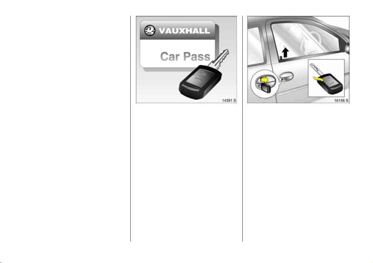
To unlock vehicle:
Press button q 3, lift door handle
To unlock using the key in the driver’s door
lock: Turn key tow ards front of vehicle, lift
door handle.
Locking from the inside: Press lock buttons.
6 Door lock s, child safety locks 3 –
pag e 50,
electronic immobiliser – page 5 1,
radio remote control 3 – page 52,
central locking system 3 – pag e 54 ,
Vauxhall alarm system 3 – page 6 0.
Page 7
To unlock luggage compartment:
Turn key clockwise as far
as it will go
In order to av oid being locked out, the key
cannot be removed.
Position of key slot in lock:
– Horizontal Luggage compartme nt
locked and
unlocked together
with central
locking system.
– Vertica l Luggage compartment
is always locked.
Radio remote control 3 – page 52,
central lock ing system 3 – page 54,
Vauxhall alarm system 3 – page 60.
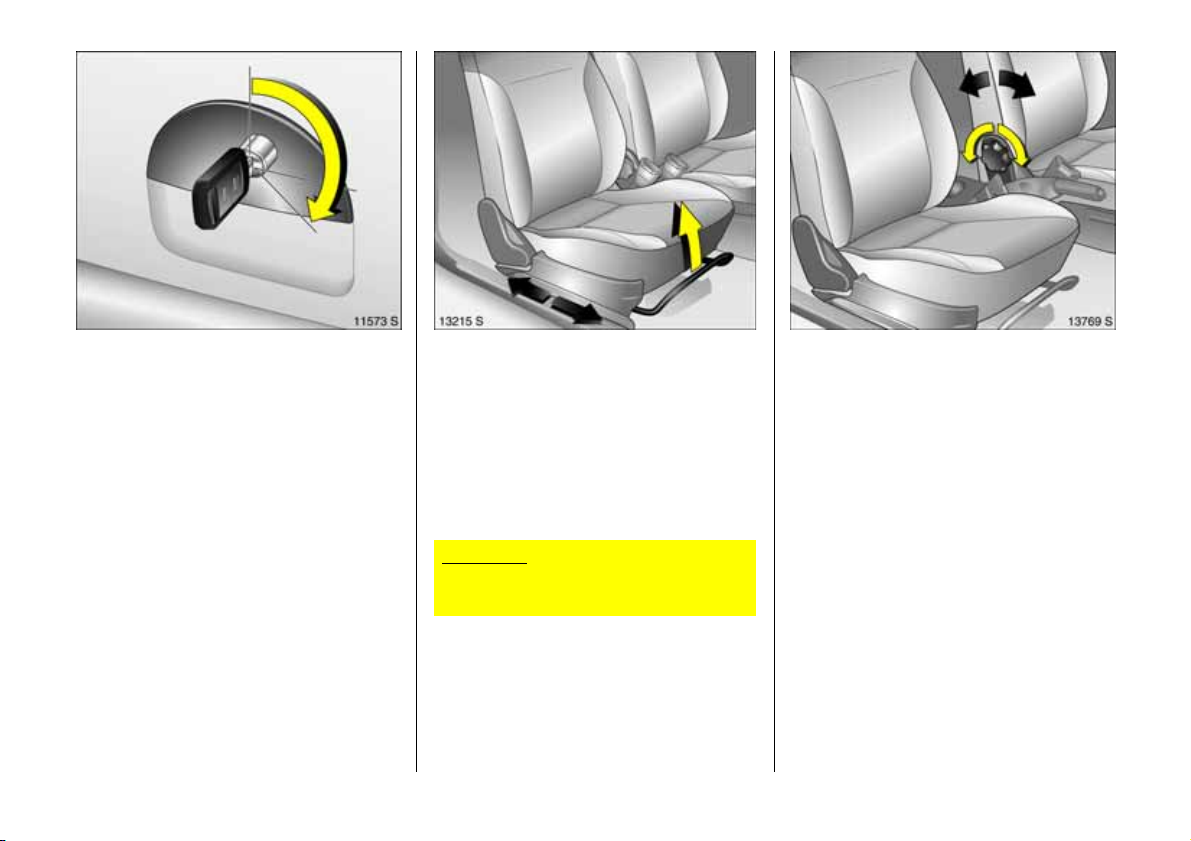
Se at a dj ust men t 3:
Pull handle, slide seat,
rel ea se handl e,
allow seat to audibly latch into
po si ti on
Nev er adjust the driver’s seat whilst driving.
It could move in an uncontrolled manner
when the handle has been pulled.
6 Seat position – see page 6 4.
Im porta nt : Do not sit nearer than 10
in ch es (2 5c m) f ro m t he s t ee ring wh ee l, t o
permit safe airbag dep loyment.
Adjusting seat backrest:
Turn h andwh eel
Move seat backrest to suit sea ting position.
Do not lea n on seat back re s t whilst
adjusting it.
6 Seat position – se e page 64.
5
Page 8
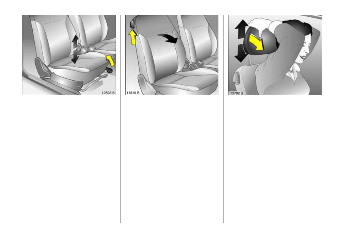
Adjusting seat height 3:
Pu ll lever at s ide
Lift lever and remove weight from seat to
rais e it or p re s s d ow n on se at with body
weight to low er it.
Never adjust the driver’s seat whilst driving.
It could m ove in a n uncontrolled m anner
when the lev er has been pulled.
6 Seat position – see pag e 64 .
6
Folding down the seat backre sts 3:
Raise release l ever
To en t er a nd leav e th e r ear s eat area, til t
front seat back forwards.
6 Seat position – see page 6 4.
Adjust ing head r est rai nt heig ht :
T ilt f orwa rd s to release ,
hold firmly and adjust height,
then release
6 Head restraint position – see pag e 64 ,
further information, removal – see page 65,
rear head restraints 3 – see page 65.
Page 9
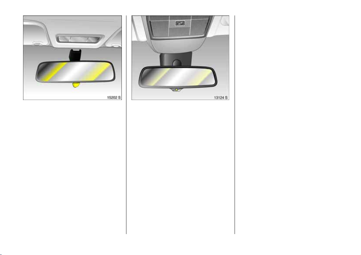
Adjusting interior mirror:
Swivel mirr or hous ing
Swivel lever on unde rside of mirror housing
to red uce daz zle a t night.
Adjusting automatic anti-dazzle
interior mirror 3:
Swi vel mirro r ho using
Dazzle at night is automa tically reduced.
The mirror does not re duce dazzle when:
z the ignition is switched off,
z rev erse gear is engaged or selector lever
set to R,
z interior lighting has been switched on.
7
Page 10
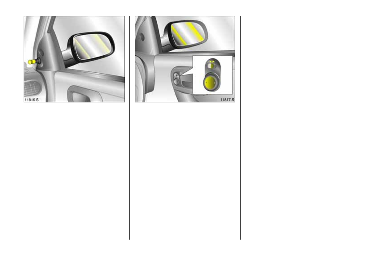
Adjusting exterior mirrors:
Swiv el i nteri or h and le in appropr ia t e
direction
6 Further informa tion, aspherical exterior
mirror 3 – page 97.
8
Electrically adjustable exterior
mirrors 3:
Four-way switch in driver’s door
Togg le switch to left or right: Four-way
switch moves appropriate mirror.
6 Furth er information, aspherical exterior
mirror 3 – see page 97 ,
heated exterior mirrors 3 – se e pag e 19 .
Page 11
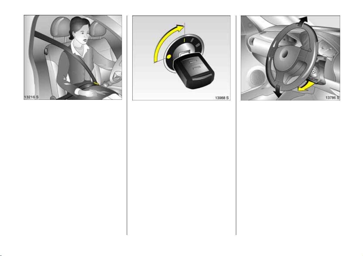
Fi ttin g sea t belt :
Draw seat belt smoothly from inertia
reel, guide o ver shoulder
and engage in buckle
The belt must not be twisted at any point.
The lap be lt must lie snugly against the
body. The backrest must not be tilted bac k
too far (recomm ende d tilting angle
approx. 25°).
To release belt, press re d button on belt
buckle.
6 Safety belts – see pages 79 to 83,
ai r bag sy st e ms 3 – see page 84,
seat p osition – see page 64.
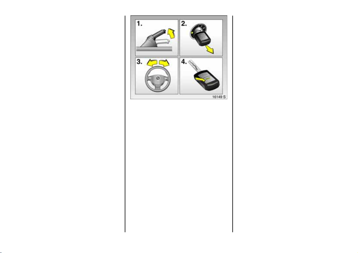
Disen gagin g st eer ing c olumn lo ck:
To re lease the loc k , move t he
steering wheel sligh tly
and turn the key to position I
Positions:
o =Ignition off
I = Steering released, ignition off
II = Ignition o n,
with dies el e ng ine: Pre heatin g
III = Start (transmission in ne utral)
6 Starting – page 23,
electronic immobiliser – pa ge 51 ,
Remove key and lock steering wheel
– see page 24.
Steering whee l adjustmen t 3:
Swivel lever down,
adju st he ight ,
swivel leve r up,
engage
Adjust steering wheel only when vehicle is
stationary and steering colum n lock is
released.
6 Airbag systems – see pag e 84 .
9
Page 12
1010
Page 13

Page
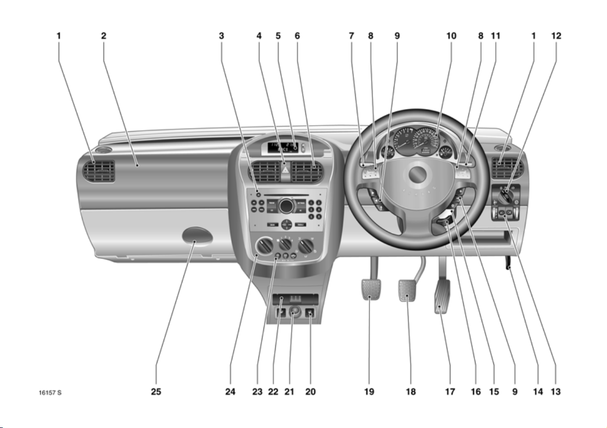
1 Side air v en ts ........ .... ..... ........ ........ 11 5
2 Front pa ssenger airbag 3 ......... ..... 84
3 Infotainment system 3 ..... ......... .... . 4 8
4 Haza rd warning ligh ts .. .... ......... ..... 17
LED for Vauxhall alarm system 3 .. 60
5 Display 3 for time, date,
outside temperature,
infotainmen t system 3 ..... .... ..... .... . 3 7
6 Centre air v en ts .... .... ......... ......... .... 11 5
7 Turn signal, headlight flash,
dippe d an d main be am ... .... ..... ..... 15
Door-to-door
light function 3 ... .... ......... .... ......... . 16
Cruise control 3 .... .... ..... .... .... ..... .... 15 0
8 Horn .... ......... .... ......... ..... ........ ..... .... .. 1 7
9 Infotainment system remote
control 3 . ..... ......... .... ......... .... ......... . 26
10 Instrume n ts ...... ..... .... ..... .... .... ..... .... . 29
Pa ge
11 Lever for w indscreen wiper
and wash system as we ll as
headlight wash system 3 and
rear window wash system 3 .... ..... .. 1 7
12 Light switch ..... ......... ........ ......... .1 5, 9 9
13 Headlig ht range adjustment 3 ..... 10 0
Fog tail lig ht .... ......... ........ ......... ..... 101
Fog lights 3 ..... .... ......... ......... ......... 1 0 1
Instrument illumination ........ ......... 1 0 1
14 Bonne t rele ase lev er . ........ ......... ...... 63
15 starte r swit c h
wit h ste ering whe el lock .. ......... ........ 9
16 Stee ring whee l ad justm ent 3 ... ........ 9
17 Ac celerator pedal .... .... ......... 138, 1 3 9
18 Brake peda l ..... .... ......... ......... 13 8 , 1 5 3
19 Clu tch ped al 3 .... ..... ........ ..... ........ 1 3 9
Page
20 Heated seats 3 .. ..... .... ..... .... ..... .... 115
21 Accessory socket or
cigarette lighte r . ..... .... ......... ......... .. 75
22 Ashtray 3 ........ ......... ......... ......... ...... 7 6
23 Air conditioning system 3 ... ..... .... 114
Heated rear window 3 ... ........ 1 9, 11 4
Air recirculation system 3 ......... .... 114
24 Heating and v entilation system .. 112
Clim ate control system 3 .... ......... . 11 9
25 Glove compartment ... ......... ......... .. 77
11
Page 14

Control indicators
X Seat belt 3:
see page 29.
q Hea dlight range adjustm ent 3:
se e p age 10 0.
> Fog lights 3:
see pages 29, 101.
A Engine electronics,
immob iliser 3,
automat ic transm ission 3,
Eas yt ronic 3,
fault:
see pages 29, 51, 146.
Z Exhaust emission 3:
see pages 30, 51, 146.
v Airbag systems 3,
belt tensioners:
see pages 80, 89.
I O il press ure:
see page 3 0.
O Turn signal lights:
see page s 16, 31.
C Main beam:
see page s 15, 31.
! Preheating 3 for diesel engines
see page 3 1.
1 Electronical ly cont rolled driv ing
prog ramm es for
autom atic trans mission 3,
sporty driv ing pr og ramm e:
see page 1 34.
T Automatic transmission 3,
Easytronic 3,
winter program me :
see page s 128, 134.
r Fo g tai l light:
see page s 31, 101.
p Alternator:
see page 3 1.
R Brake system,
clutch system:
see page 32.
u Anti-lock brake system 3:
see page 154.
S Engine oil lev el 3:
see pages 3 2, 212.
EPS Electr onic powe r ste ering 3:
see page 32.
v Traction Control System (TC
Electr oni c Stability Program
Plus
(E SP
)3:
see page 148.
Plus
g Trailer turn signa l 3:
see page 32.
Y Fue l le vel:
see pages 3 2, 36, 170.
y Seat occup ancy recog nition 3:
see pages 8 9, 90.
) 3:
12
Page 15

Lighting
Lig ht s witch ,
st alk p osi tio ns :
see pages 15, 99,
7 Lig h t s o ff,
8 Park ing lights,
9 Dipped and main beam.
0 Courtesy light:
se e p age 10 1.
C Main beam:
see page 15.
O Turn signal lights:
see page 16.
> Fog l ights 3:
se e p age 10 1.
r Fog t ail lig ht:
se e p age 10 1.
k Instrume nt illum ination :
se e p age 10 1.
? Hea dlight range adjustment 3:
se e p age 10 0.
Clim at e contro l
x Air flow:
see page s 113, 122.
Air distribut ion:
see page s 113, 122,
V To windscreen and
front door window s,
J To windscreen, front
door windows
and footwell,
K To footwell,
L To hea d area and footwell,
M To head area .
Ü Heated rear window 3:
see pages 114, 121 .
n Air conditioning system 3:
see page 114.
4 Air recirculation system 3:
see page 114.
AUTO Automatic mode 3:
see page 120.
ECO AC compressor
activ ation/ de act ivation 3:
see page 122.
ß Heated seats 3:
see page 115.
¨ Haza rd wa rning lig hts:
see page 17.
13
Page 16

Sun roof 3
l Sun roof
op ening/lowering:
se e p age 10 6.
\ Sun roof
closing/raising:
se e p age 10 6.
Fo ldin g su n roof 3
\ Folding sun roof
op en in g:
see pages 107, 109.
l Foldi ng sun roof
closing:
see pages 107, 109.
Windscreen wiper
Stalk positions:
see page 17,
§ Off,
$ Interval operation or
automat ic wi per
with ra in sensor 3;
% Slow,
& Fast.
Date, ti m e, in fo rma t io n di splay,
Infotainment system
Inform ation d isp lay 3:
see page 3 7.
Ö O n button for date and time,
; Setting buttons for date and time
Infotainment system
remote contr ol 3:
see page 2 6.
Cruise control 3
Buttons on tu rn sig na l stalk:
see page 1 50.
I Activate, store , accelerate
R Resume
stored speed, decelerate
§ Deactivate.
Mi scellaneous
p Central l ocking sy stem 3:
loc king – see pag e 54 .
q Central l ocking sy stem 3:
unlocking – see page 5 4.
j Horn:
see page 17.
T Wi n ter pro gram ,
automa tic transm ission 3,
Eas y tronic 3 :
see pages 128, 134 .
+ Fir st- aid kit (cus hion) 3:
see page 174.
¨ Warnin g tri angle 3:
see page 174.
14
Page 17
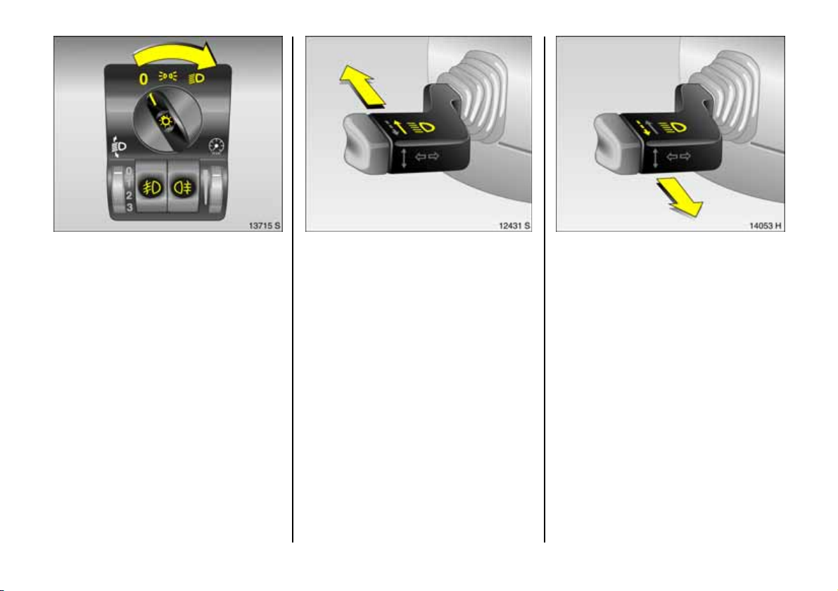
Light switches:
7 =Off
8 = Parking lights
9 = Dipped or main beam
Press 0 =Courtesy light
Press > = Fog lights 3
Press r = Fog tail ligh t
6 Furthe r informa tion – page 99,
headlig ht warning device – page 24,
headlig ht ra nge adjustment 3 – pa ge 10 0,
daytime running lights – page 99.
Dipped and main beam switch:
Main beam = Push lever forward
Dipped beam = Push lever forward
again
Blue control indicator C is lit when main
beam is activated .
Headlight flash:
Pull stalk to wards steering wh eel
15
Page 18
To activate door-to-door light
funct io n:
Key to o an d r em o ve ,
open driver’s door,
pull tu rn sign al stalk tow ard steering
wheel
The dip ped beam remains on for a furthe r
3 0 se cond s a fte r cl o si n g t h e dr ive r’s do or.
If the driv er’s door is left open , the ligh ts will
go out after tw o minutes.
Door-to-door lighting can be deactivated
by inserting the key in the starter switch or
by pulling the turn signal stalk toward the
steering wheel again.
16
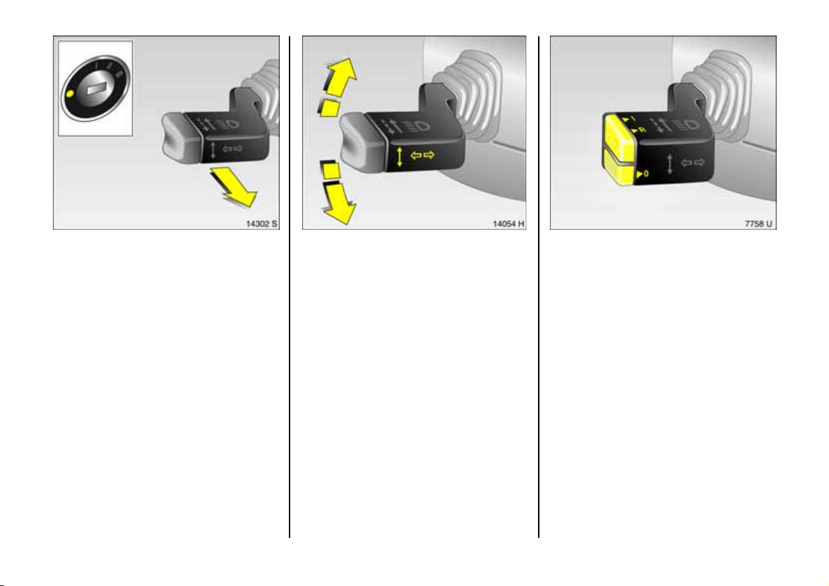
Operating turn signal lights:
Lever in rest position
righ t = up
lef t = dow n
When the steering wheel is turned back, the
lever automatically retu rns to its original
position. This will not happen whe n mak ing
a minor steering manoeuvre such as
changing lane.
When lane changing, m ove lever to
resistance point. When released, the lever
will spring back.
To operate cruise c o ntrol 3 :
Press buttons on stalk
Switch on: tap button I.
Switch off: tap button §.
Resume at stored speed: tap button R.
6 Cruise control 3 – see p age 150.
Page 19
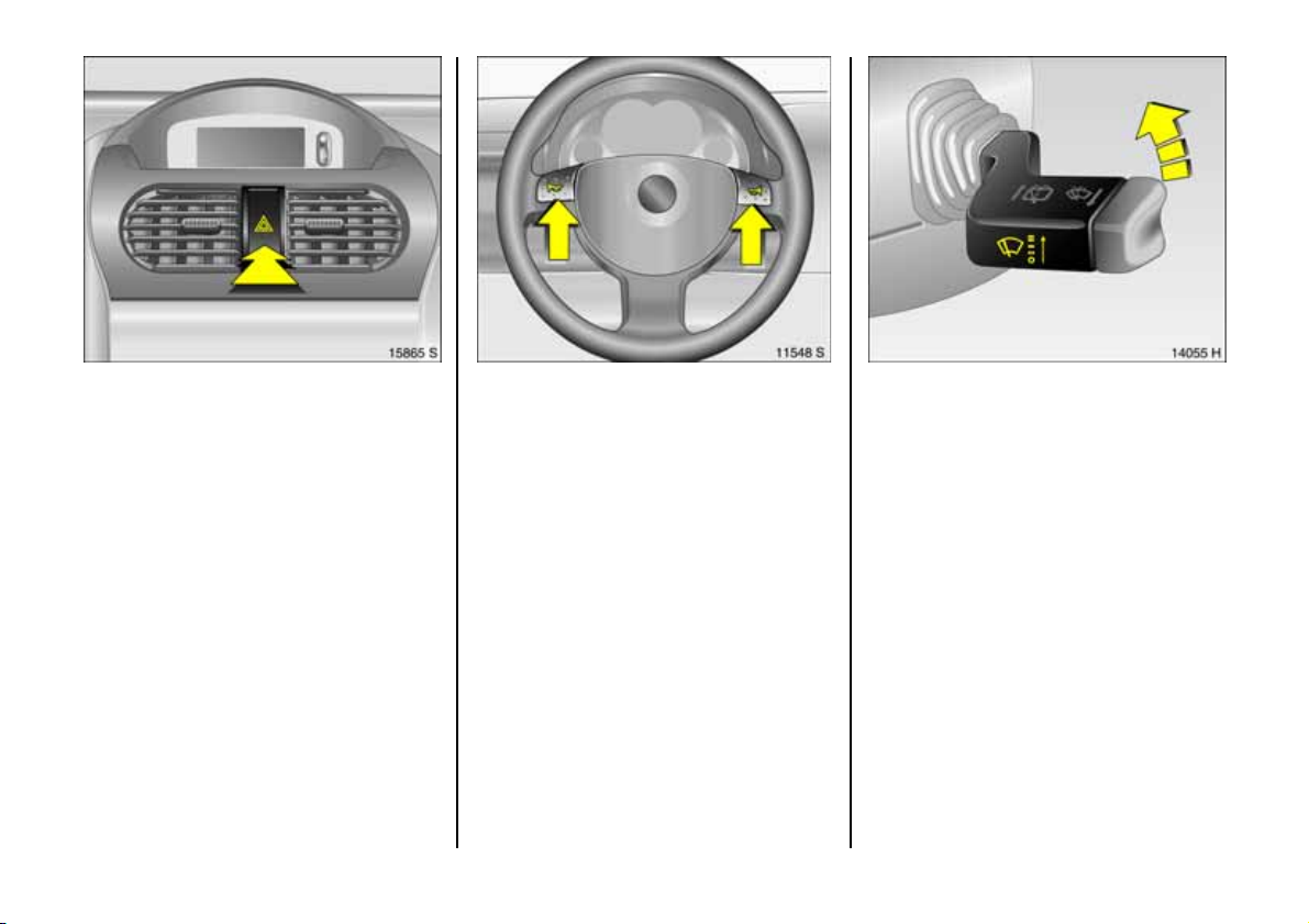
Hazard warning lights:
On = Pre ss ¨
Off = Press ¨ again
To aid location of the pushbutton, the red
surface is illumina te d when the ignition
switched on. When the button is pressed,
its control indic ator flashes in time with the
hazard warning lights.
Ho rn o pera tio n:
Press j
6 Airbag systems 3 – pa ge 84,
remote control for radio
and Infota inm ent system 3 – see pag e 26 .
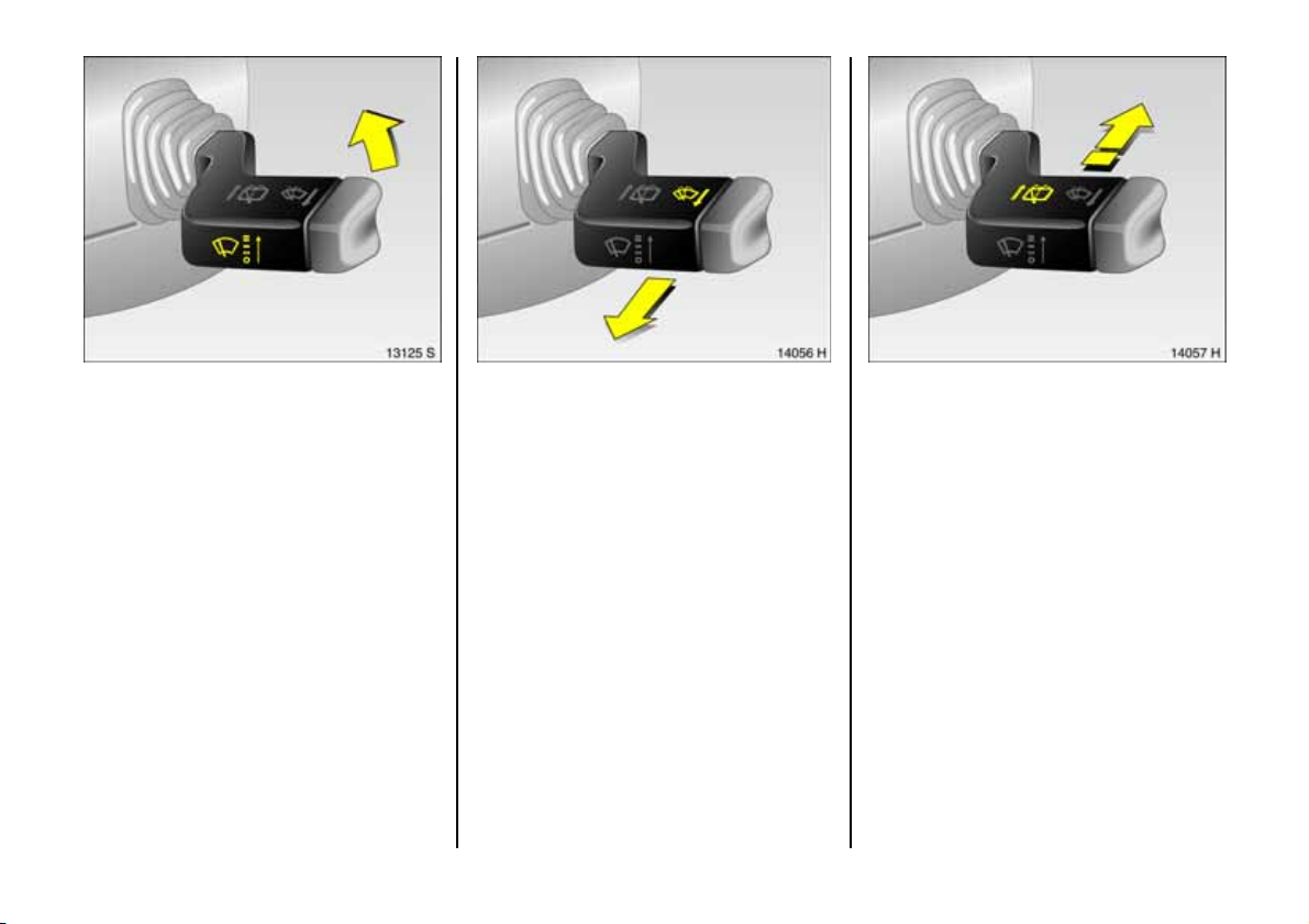
Windscreen wiper:
Stalk up
§ = Off
$ = A dj us tab le inte rv a l
% = Slow
& = Fast
Setting wiper interval to a va lue between 2
and 15 seconds:
Stalk to inte rval switching $,
Stalk to §,
Wait for d esired interval,
Stalk back to interv al switc hing $.
The interval re mains stored until the ne xt
change or until the ig nition is switched off.
Switc hing the ignition off and m oving the
stalk to $ sets the interval to 7 seconds.
17
Page 20
Automatic wiper with rain sensor 3:
Move lever up
§ = Off
$ = Automatic wiper
with rain sensor
% = Slow (constant)
& = Fast (constant)
Automatic wiping $ : T h e rain se n sor
detects the amount of water on the
windscreen and automatically regulates
th e w inds cre en w ipe r.
Pu sh l e ver do wn t o sw itch o f f .
If necessary, the positions % or & can be
selected manually.
18
Operating windscreen and
headli ght wash systems 3:
Pull stalk towards steering whee l
The wipe r will s wipe for a few strokes.
The headlight wash system 3 ca n be
op erated when the lights are on.
On vehicles fitted with ra in sensor 3, kee p
the sensor area clean.
6 Further information –
see pages 218, 224.
Operating rear window wiper and
wash sys tem s 3:
Wiper on = Push lever forward
Wiper off = P ull l ever to wards
stee ring wheel
wa sh = P ush le ver forward
and hold
The rear window w iper swipes in time d
interval mode.
The wip er will swipe for a few strok es wh en
washing.
6 Further inform ation –
see page s 218, 224.
Page 21

Heated rear window 3,
hea ted ext eri or mi rrors 3:
On = Pre ss
Ü
Off = Press Ü again
Rear window and exterior mirror heating
with ignition sw itched on. Control indicator
in switch.
6 Further inform ation –
see page s 114, 121.
Clear ing misted or icy windows:
Tu rn rota ry s witch es f or te mpera t ur e
and air fl ow cl oc k wis e,
set air distribution to
V,
press air conditioning switch n 3
Close centre air vents; p ush sliders inw ards.
Direct s ide air vents towards d oor windows.
6 Climate control – se e pa ge 112,
air conditioning system 3 – se e page 114,
electronic air conditioning syste m 3 –
see page 119.
To set automatic mode of
au tom a tic climat e c o ntro l syste m 3:
Press AUTO button,
se t tem pe rat ur e
using rotary knob
Open all air vents.
6 Electronic air c onditio ning s ystem 3 – see
pag e 119.
19
Page 22
Information display 3:
Disp la y of in fo rma t io n
–Time,
– Outside temperature,
–Radio 3 or date,
– Navigation 3,
– Telephone 3,
–Trip computer 3 .
6 Information Dis play – see page 37.
20
Manual trans mission:
Reverse gear: With vehicle s tationary,
pull the ring up three seconds after
de-clutching an d engage gear.
If the gear does not engage: With le ver in
ne utra l, briefly release clutch pe dal and
depress again, then repeat ge ar selection.
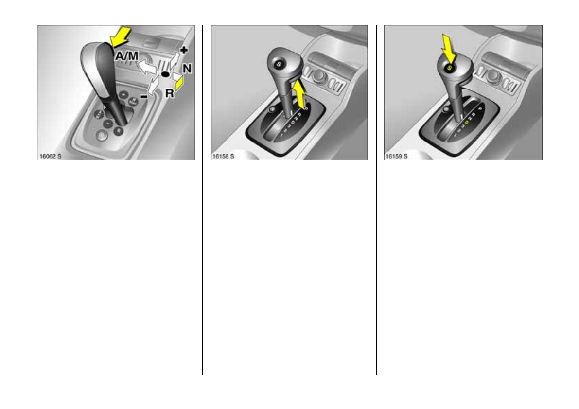
Easytronic 3:
N = Neutral/Start position
o = Centre position
(Drive position)
+ = Higher gear
- = Low er ge ar
A/M = Change between
Automatic and
Manual mode
Only start in N with foot brake applie d.
6 Further information – page 126.
Page 23
Easytronic 3:
R =Reverse
(wit h s ele ct or lever lock)
To move the selector lever from N to R
press the button on the lever.
6 Further information – page 126.
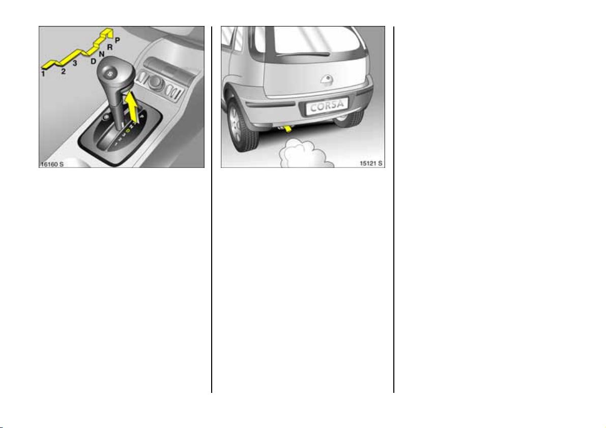
Automatic transmission 3:
P = Park
(with selector lever lock)
R = Reverse
N = Neutral
Only start in P or N , to leave P swi t ch
ignition on, app ly foot brake and pull
ha ndle be neath selector lever.
To engage P or R pull release under
selector lever.
P: Only w ith vehicle stationary,
first apply han d brake
R: Only with vehicle stationary
6 Automatic transmission – see page 132.
Automatic transmission 3:
D = 1st to 4th gear
3 = 1st to 3rd gear
2 = 1st and 2nd gear
1 = 1st gear
also
S = sporty driving programm e
Select 3, 2 or 1 if c ertain gears are not
desired, e.g. 4-3-4 . . . on winding roads, or
in order to utilize the engine braking e ffect
whe n driving downh ill.
To select 3 or 1 pu ll ha nd l e be n ea t h
selector lever.
6 Automatic transmission – see page 13 2.
21
Page 24
Automatic transmission 3:
Protection against unintentional
engagement of P, R, 3 or 1
Pull release under selector lever 1, P: U p to
final stop.
When selecting any p osition from 1 to N or
from R to D d o no t p ul l ha n dl e b e ne a t h
selector lever.
6 Automatic transmission – see page 13 2.
Exhaust gases are poisonous
Exhaust gases contain carbon monoxide,
which is extrem ely poisonous but is
od ourl e ss a n d co l o ur les s.
Therefore nev er inhale exhaust gases, and
ne ver run the engine in an enclosed space.
Also avoid driving with the lugga ge
compartment op en. Otherwise exhaust
fumes could penetrate the vehicle interior.
Befo re st a rt ing of f, check:
z Tyre pressure and condition –
see pages 157, 243 .
z Engine oil level and fluid le vels in e ngine
compartme nt – see page s 211 to 218.
z All windows, mirrors, exterior lig hting
and nu mber plates are free from dirt,
snow and ice a nd operational.
z Do not place any objects in front of the
rear window, on the instrument panel or
in the area in which the a irbags inflate.
z Seats, seat belts and mirrors are
correctly a djusted .
z Check brakes.
22
Page 25
Sta r ting , petr ol en gin e:
Ma nu al tran smi ssion in ne utra l
with clutch depressed,
pre ss foot brake, Easytronic
automatic transmission
3 in N ,
3 in P or N,
do not accelerate,
turn key to III
The initially increased engine speed
automatically falls as the engine
tem perature r ise s.
Before repeating the starting proced ure,
turn the k ey back to o in the starter switch,
remove it and then reinsert it. Then re peat
the starting procedure.
6 Electronic imm obiliser – page 51,
further information – page s 138, 139, 170.
Starting, di esel en gine:
Manual trans mission in neutral
with clutch depressed,
pr e ss fo ot b r ake ,
automatic transmission
3 in P or N,
do n ot ac ce ler a te,
tu rn key t o II;
af te r pr ehe ati ng c on tr ol i ndic ato r
go e s o ut
1)
,
turn key to III
Before repea ting the starting proc edure,
turn the key back to o in the starter switch,
remove it and then reinsert it. Then repeat
the starting procedure.
6 Electronic immobilis er – page 51,
further information – pages 138, 139, 170.
1)
Preheating system switches on only if ou tside
temperature is low.
Releasing the hand brake:
Raise leve r s ligh tly,
press lock button,
lower lever fully
And now "Have a good journey!"
Drive carefully, economically and with the
environment in mind. While driving, do not
do a nything that c ould distract y ou.
23
Page 26
Warning buzzers
While driving:
z If seat be lt is not fastene d 3,
z If a specified max imum speed is
exce ed ed 3.
When the vehicle is parked and the driver’s
door is opened:
z When the ignition key is in the starter
swi tch ,
z If parking lights or dipped beam are on,
z If the turn signal stalk is e ngage d.
Parking t he vehicle:
Apply handbrake firmly,
engine off,
rem ove ke y,
lock s te ering wh eel,
lock door s
To lock , press button p or turn key in lock
tow ards rear of vehicle. To activate anti-
the ft lock ing system 3 and Vauxhall alarm
sy ste m 3, pres s bu tto n p twice.
6 Further information – pages 51, 138,
ra di o rem o te co n tro l 3 – page 52,
central locking s ystem 3 – page 54,
Vauxhall alarm system 3 – page 60.
Advice when parking:
z Alw ays apply hand brake firmly. On
slopes apply the hand brake a s firmly as
possible.
z With m anual transmis sion, engage firs t
gear or re verse ge ar. With Easytronic 3,
place selector lever in mid pos ition
before switching off ignition. With
autom atic transmission 3 , place selector
lever in P.
z Close window, sun roof 3 and folding
top 3.
z On vehicles with Easytronic 3 the control
ind icator R flashes for a few seconds
after the ignition is switched off if the
ha nd brake has no t b ee n a p p l i ed .
z In vehicles with autom atic
tra nsmission 3 th e k e y ca n on l y b e
removed when the selector lever is in P.
z Turn steering wheel until lock is fe lt to
engage (an ti-theft protection).
z Engine cooling fan may run on after the
engine has been s witch ed off.
z Do not park vehicle on easily ignitable
surfaces as the hot exhaust system
tempe rat u res co uld cau s e the s urface t o
ignite .
24
Page 27
Servi ce wo rk ,
Ma in tena nc e
We recommend tha t you entrust all w ork to
your Vauxhall Authorised Repairer, who
can provide y ou w ith reliable service and
correctly perform all work accordin g to
factory instructions.
6 Vauxhall S ervice – page 208,
service interval display – page 210.
Ge nuine Vauxhall Parts and
Accessories
We recom mend that you use "Genuine
Vauxhall Parts and Accessories" and
co nv er s ion p arts r e leas ed ex pres sly f or
your vehicle type. These parts ha ve
unde rgone specia l tests to establish their
reliability, safety a nd specific suitability for
Vauxhall vehicles. Despite continuous
market monitoring, we cannot assess or
guarantee these attributes for other
products, even if they have been granted
approval by the relevant authorities or in
some other form.
"Genuine Vauxhall Parts and Accessories"
and conversion parts approved by
Vauxhall can be obtained from your
Vauxhall Authorised Repairer, of course.
Here you will also be giv en compre hensive
advice about permitte d technical ch anges
and correct installation w ill take place.
For your s afety
Carry out regularly the checks
recom mende d in the individual sections
of this Owner’s Manual.
Ensu re th at y our v ehicle is se rv iced as
specified in the Service Booklet. W e
recommend that you consult your
Vauxhall Authorised Repairer.
Have faults remedied without delay!
Consult a workshop. We recommend
your Vauxhall Authorised Repairer. If
necessary, interrupt your journey.
6 Maintenance – see page 210.
That was a brief look
at the most important
info rm at io n fo r you r firs t dr iv e in
your Corsa/Combo.
The other pages
of this chapter
contain a description of some
interesting functions
in your vehicle.
The remaining chapters
of the Owner’s Manual
con ta i n imp o rtan t info rmat io n
on operation, safety
and maintenance
as well as a full
index.
25
Page 28
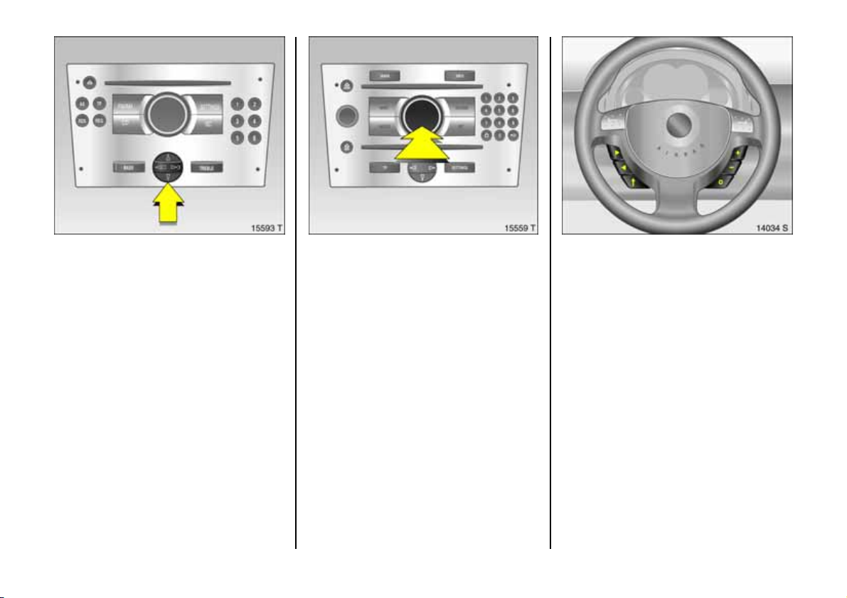
Infotainment system operation
Functions are selected and executed in the
menu on the display using the four-way
button, the multifunction b utton 3 on the
Infotainm ent system or the buttons 3 on
the steering wheel. Corresp onding menu
options are shown on the display.
Selecting with four-way button:
Press four-way button up, down, right or
left.
26
Selecting with multifunction button:
Pre ss and turn multifunction button.
To exit a menu, turn multifunction button
left or right to Return or Mai n and select.
Selec ting with steering wheel buttons:
Select menu options via the menus using
the buttons.
For further information, see Infotainm ent
system instructions.
Page 29

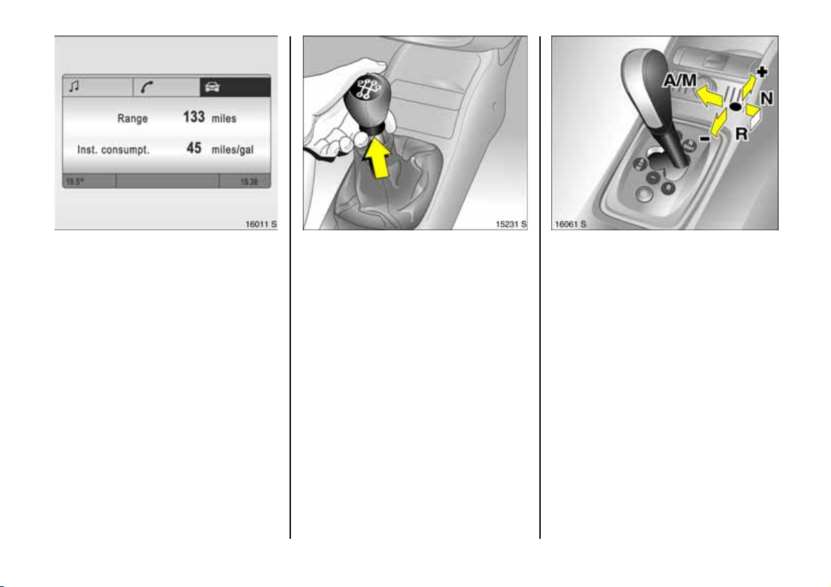
Trip comp ut er 3
The trip computer shows vehicle data that
is continually recorded and evaluated
electronically.
Functions:
z Rang e
z Instantaneous consumption
z Dis ta n ce
z Average s p ee d
z Trip consumption
z Average consumption
z Stop watch
Vauxhall Full Size airbag system
The V auxhall Full Size airbag system
co m p r ise s seve ra l ind ividu al s yste m s .
Fro n t a irbag sy ste m
The front airb ag system is triggered in the
event of a s erious accident involving a
frontal impa ct and forms safety cus hions
for the driver and front passenger. The
forward movement of the driver a nd fron t
passenger is checked and the risk of
injuries to the upper body and head
thereby substantially re duced.
Side airba g system 3
The side airbag system trigge rs when a
side-on collision occurs and provide s a
saf ety barrier fo r the dri ver a nd/or
passenger in the respective front door
area. This reduces the risk of injury to the
upper body considera bly in cas e of a side
impa ct.
Curtain ai rbag system 3
The curtain a irbag system triggers in case
of a side-on collision and provid es a safety
barrier in the hea d area on the respective
side of the vehicle. This reduces the risk of
injury to the head considerab ly in case of a
side-on collision.
6 Further information – page 84.
27
Page 30
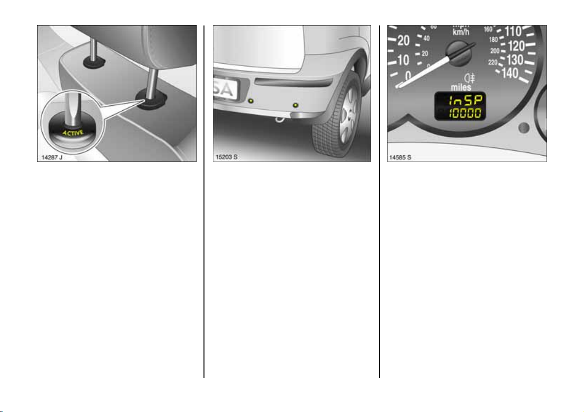
Active head restraints 3
In the event of a re ar-end impa ct, the
active head restraints automatically tilt
forward a little . The head is more
effectively supported by the head restraint
an d th e dan ger of inj u ries cau s ed by
whiplash in the a re a of the neck is reduced.
Active head restraints can be identified by
the lettering ACTIVE on the head restraint
guide bushes.
28
Parking distance sensor 3
The parking distance sensor automatically
switches itself on whe n reversing.
If the vehicle a ppro aches an o bstacle w hen
reversing, a series of signals can be heard
in the vehicle interior. The interval be tween
the sig na ls b ecome s sho r t er a s the
distance is reduced. If the distanc e is less
than 30 cm, the signal will be continuous.
6 Further information – page 151.
ECOService-Flex
The oil change and service intervals are
flexible, based on a number of different
param eters and the conditions un der
which the vehicle is used. Various engine-
spec ific data is continuously recorded and
used to calculate the remaining distance
until the next service is due.
To display remaining dis tance:
z Ignition off.
z Press reset button below speedometer.
z Ins P and the remaining dis tance are
displayed.
Page 31

Instruments
Control indicators
The c ontrol indicators described here are
not present in all vehicles. The de scription
applies to all instrument v ersions.
X
Seat belt 3
Warning light lights up (accompanie d by
an acoustic warning) when ignition is
swi t c h e d o n : F a ste n yo ur s eat b e lt – see
page 81.
?
Automatic headlight range adjustment 3
Lit: Fault in system. Contact a w orkshop
immediately. W e recommend your
Vauxhall Authorised Re pairer. See page
100.
>
Fog lights 3
Control indica tor lights up whe n fog lights
are s wit ched on.
A
Engine electronics, transmission
ele ctro nics , imm obilis er, d iese l fue l fi lte r 3
Control indicator lights up for a few
seconds when engine is switched on.
Lights when the engine is running
Fault in engine electronics or transmission
electronics. Electronics switch to
emergency running programme. Fuel
cons umption may increase and driveability
of the vehicle may be impaired – see
pag e 146. Contact a w orkshop. We
recommend your Vauxhall Authorised
Repairer.
If it flashes when the ignition is on
Fault in the e lectronic immobiliser system;
th e engi n e c annot be s tar ted – see
pag e 51.
29
Page 32

Lights when the engine is running
Engine lubrication m ay be interrupted. This
ma y result in damage to the e ng ine and/or
locking of the drive wheels:
1. Depress clutch.
2. Move gear shift lever to n eutral; with
autom atic transmission 3 and
Eas yt ronic 3 m ove selector lever to N .
3. Move out of the flow of traffic as quickly
as possible without impeding other
vehicles.
4. Switching the ignition off (Position I).
Z
Exhaust emission
Control indicator lights up when ignition is
switched on and goes out shortly after
engine starts.
Lights when the eng ine is running
Fault in emission control system. The
permitted emission limits may be
exceeded. Consult a workshop. We
recommend your Vauxhall Authorised
Repairer.
If it flashes when the engine is running
For fau lt that can lead to destruction of the
catalytic conv erter, see page 146. C onsult
a w orkshop imm ediate ly. We recomm end
that you consult your Vauxhall Authorised
Repairer.
30
v
Airbag systems 3,
belt ten sioners
see pages 81, 89.
I
Oil p re ssure
Control indica tor lights up whe n ignition is
switched on and goes out shortly after
engine starts. Can lig ht up intermittently
when idling with hot engine ; must go out
wh en e ngin e spee d is i n creas ed.
When the ignition is off, c onsiderab ly
mo re force is n e eded t o brak e an d ste er .
Do not remove key until vehicle has
come to a standstill, otherwise the
steering column lock c ould engage
un ex pe ct edl y .
Consult a workshop. We recommend your
Vauxhall Authorised Repairer.
Page 33

O
Turn signal lights
The corresponding control indicator
flashes when th e turn signal is activated.
Both flash when the hazard warning lights
are active. Rapid flash: A turn signal bulb is
faulty. Bulb re place ment – see page 194.
1
Electronicall y contr ol led driving
prog ramm es for
autom atic trans mission 3
Control indicator lights up when sporty
driving program me is enabled.
Further information – see page 134.
T
Wi nt er pro gra m me fo r
automat ic transm ission 3 and
Eas y tronic 3
Control indicator lights up when winter
program is enabled.
Further inform ation – see pages 128, 134.
C
Main beam
Control indica tor lights up whe n main
beam is on and when he adlight flash is
op er at e d.
!
Preheating 3 for diesel engines
Control indicator lights up during
preheating.
Preheating system switches on only if
outside temperature is low.
r
Fog tai l light s
Control indicator lights up when fog tail
light is switched on.
p
Alternator
Control indicator lights up when ignition is
switched on a nd goes out shortly after
engine starts.
Lights when the engine is running
Stop the vehicle and switch off the engine.
The battery is not be ing charge d. Engine
cooling may be interrupted. Contact a
workshop. We recommend your Vauxhall
Authorised Repairer.
31
Page 34

R
Bra k e sy s t em ,
clutc h syste m
The c ontrol indicator lights when the
ignition is switched on if the hand brake is
applied or if the brake or clutch fluid level is
too low. Further information – see
pages 154 , 216.
If lit when hand brak e is not applied:
Stop the vehicle; interrupt your journey
immediately. Consult a workshop. We
recommend your Vauxhall Authorised
Repairer.
On vehicles with Easytronic 3 control
indicator R flashes for a few sec onds afte r
the ig nition is switched off if the hand
brake has n ot been applie d.
u
Anti-lock brake system 3
see page 154.
S
Engine oil l ev el 3
Lit: E ngine oil level is too low. Check engine
oil level and top up if necess ary. See
page 212.
1)
EPS
Electric power steering 3
The control indicator lig hts up for a fe w
se c o nd s w hen the ign ition is sw itche d on.
Illum ination while driving indicates a fault.
Driv ing may be continued. More force is
required for steering. Consult a workshop.
We recommend your Vauxhall Authorised
Repairer.
v
Traction Control System (TC
Electronic S tabil ity Prog ram (E SP
see page s 148, 149.
Plus
) 3,
Pl us
) 3
g
Trai ler turn signal 3
When tow ing a trailer or caravan, indicator
light flashes at same speed as turn signals.
Does not flash if trailer or towing vehicle
turn signal fails.
Y
Fuel level 3
Lit: Low fuel level. Fuel gauge in reserve
area.
Flashing: Fuel supply used up, fill tank
imm ediately.
Neve r let the tank run dry!
Petrol engines: Erratic fuel supply can
cause catalytic conve rter to overheat. See
pag e 144.
Diesel engines: If the tank is run dry, bleed
th e fue l sy ste m as de scrib ed on pag e 17 0.
32
1)
EPS = Ele c t ri c P ower Steering.
Page 35

y
Seat oc cupancy recognition 3
see page s 84, 89.
Transmission display 3
Display of selector le ver position for
autom atic transmission 3 or current gea r
or mo d e fo r Ea s yt r o nic 3.
Further inform ation – see pages 126, 132.
33
Page 36

Trip odometer
To return to zero, depress reset k nob with
ignition switched on and trip odometer
display activated.
Vehicles with clock in odometer
To set to z ero, hold reset knob down for
approx. 2 seconds with ignition switched
on and trip od om eter activated.
To switch between trip odometer and clock
display 3 gi ve re set kno b a br ie f p re s s – se e
next page.
Service interval d isplay, see page 210.
Tachometer
Indicates engin e spe ed.
Warn ing zone: M aximum p ermissible
e ngine sp eed ex ceeded ; dan ge r to en gine.
34
Spee dom eter
Indicates the vehicle speed.
Odometer
Records the kilometres driven.
Page 37

Ti me di splay in odomet er 3
To switch between trip odometer and time
display 3 give reset knob a s hort press.
W h en the veh icle lights are on, the
brightness of the display can be adjusted
using the right-hand adjuster wheel k
below the light s witch – se e page 101.
Setting the time
With time displayed, press reset knob in
instrument:
Pre ss for approx . 2 seconds ,
Hours flash,
Pre ss brie fly ,
Set h ours,
Pre ss for approx . 2 seconds ,
Minutes flash,
Pre ss brie fly ,
Set minutes,
Pre ss for approx . 2 seconds ,
Clock is star ted .
35
Page 38

For physical re asons, the engine
temperature gauge shows the coolant
temperature only if the coolant level is
adequate.
Durin g oper ati o n the s ystem i s pres suri s ed.
The temp erat u re ma y there fore rise briefl y
to over 100 °C.
Co ol an t te mp era t ur e d i sp lay
Pointer in zone
at left = Engine operating
temperature not
yet reache d
Pointer between
the zones = Normal ope rating
temperature
Pointer in red
zone = Temperature too
high :
Stop ve h icle an d
switch off engine.
Danger to engine.
Check co olant level
immediately – see
page 215.
36
Fuel gauge
Pointer in red
warning z one or
Y lit = Reserve level.
Pointer in red
warning z one or
Y flashing = Refuel –
Never run the tank dry!
Because of the fuel remaining in the tank,
the amount of fuel required to fill the tank
may be less than the specified tank
cap acity.
see pag e 143.
Page 39

Fault display
--.-°C or F on the display indicates a fault.
Have the cause of the fault remedied. We
recommend that you consult y our Vauxhall
Authorised Repairer.
Information display
Tripl e inform ation d isp lay 3
Display of time, outside temperature and
date/Infotainment system is switched on.
When the ignition is off, the time, date and
outside temperature can be made to
appear for approx. 15 se conds by briefly
pressing one of the two buttons adjacent
to the display .
Graphica l Informa tion Display 3
Display of time, outside temperature a nd
date/Infotainment system is switched on.
The information that is displayed depends
on the Infotainment system c onfiguration.
37
Page 40

Tr ip l e info rm atio n display
Setti ng tim e a nd date
Infotainment system off. Press Ö and ;
next to the display as follows:
Press Ö for ap prox. 2 seconds:
Day fla shes
;:Set day
Ö:Month flashes
;:Set month
Ö:Year flashes
;:Set year
Ö:Hours flash
;:Set hours
Ö: Minutes flash
;: Set minutes
Ö: Clock is starte d.
Correcting time 3
Some RDS transmitters do not send correct
tim e signals. If the incorrect time is
displayed often, de activate the automatic
tim e synchronisation 3 and set the tim e
manually.
The automatic setting is indicated by Ö in
the display.
Correcting us ing RDS:
In fo t ain me nt syste m o f f . Pres s Ö and ;
ne xt to the display as follows:
Hold down Ö for approx. 2 sec., c lock
display is now in setting mode,
Pre ss Ö twice (until year flashes),
Pre ss Ö and hold down for ap prox.
3 seconds until } flashes in display and
text "RDS TIM E" a ppears (years fla sh
during this time),
Pre ss ; ; Dis play o f
RDS TIME 0 = Off.
Pre ss ; ; Dis play o f
RDS TIME 1 = On
Pre ss Ö three times.
Graphical information display 3,
se lec t ing fun c ti ons
Th e fu n cti o n s a nd se tting s of s o me
equipment 3 can be accessed via the
graphical information display.
Functions are selected and executed in the
menu on the display using the four-way
button, the multifunction button 3 on th e
infotainment system or the buttons 3 on
the steering wheel.
38
Page 41

Selecting with four-way button:
Select menu options via the menus using
the buttons or the four-way button on the
infotainmen t system.
Selecting with multifunction button 3:
Tu rn Mark menu options,
functions or commands,
Pre s s Select marked item or
confirm comma nd.
To exit a menu, turn the multifunction
button left or rig ht to Return or Main and
se lect.
Selec ting with steering wheel buttons 3 :
Select menu options via the menus using
the buttons.
6
39
Page 42

Some dis plays and menus can be selected
by selecting the function in the top row of
the display:
z Au dio
z Navigation 3
z Te le ph o ne 3
z Tri p c o mp ut er 3
For audio, navigation 3 and telephone
func tions 3, see Infotainment system
instructions.
40
System settings
Settings are made in the Settings menu.
Pre ss Main button 3 (not found on all
In fo t ain me nt sy ste m s) on Infotai n me nt
system (call up m ain displa y).
Pre ss Settings button on Infotainme nt
sy ste m.
Th e Setti ng s menu will b e display ed.
Sett ing tim e a nd dat e
Selec t menu ite m Time, D a te fr o m th e
Sett ings me nu.
The Time , Date menu will be displayed.
Selec t the menu items required.
Make the desired setting.
Page 43

Correcting time 3
O n sy ste m s w ith GPS rec ei ve r1), time a nd
date are automa tica lly set upon receipt of
a GPS satellite signal. If the displayed time
does not correspond to local time, time can
be manually corrected in 30-minute
increments or automa tically corrected via
receipt of an RDS time signal2)3.
Some RDS transmitters do not send correct
time signals. If the incorrect time is
displayed often, deactivate the automatic
time synchronisation 3 and set the time
manually.
The automatic setting is indicated by Ö in
the display.
To correct with the h elp of RDS, select
Synch ron. clock autom atica l. from the
Time, Date menu.
The field for Synchron. clock automatical.
is ticked .
Language selection
You can select the display language for
some f u nc tio n s .
Select menu item Language fr om t he
Settin gs menu.
The ava ilab le languages are d isplayed.
Selec t the de sired lan guage .
Selec tions are indicated b y a 6 in front of
the menu item.
On system s with language version 3, upo n
change of the language setting for the
display, you will be asked if the m essage
language is also to be c hanged. See
Infotainment system instructions.
1)
GPS = G lo b a l P ositioning Sys t em ,
Satellite system for wor ld-w ide p osi tioning .
2)
RDS = Radio Data S ys te m .
41
Page 44

Sett ing displ ay m ode 3
The display can be ada pted to lig ht
conditions: black text on a light
background or white text on a dark
bac kground.
In menu item Da y /N ig ht from the Sett ings
menu.
Setti ng units of me asure
You can select which units of measure are
to be used.
Select menu item Units from the Settings
menu.
The a vailable units are displa yed.
Select the de sired unit.
Selections are indicate d by a o in front of
th e m enu item .
42
Adjust contrast 3
Select menu item Contrast from the
Settin gs menu.
Th e Cont rast me nu will be displayed.
Confirm the required setting.
Page 45

Th e alte rnat ives are dis pla ye d.
Autom atic: adapte d based on vehicle
lighting.
Alw ays da y design : black text on light
background.
Alw ays night design: white text on da rk
background.
Selections are indicate d by a o in front of
th e m enu item .
Ig ni tion logic 3
Se e In fo t ain me nt sy ste m instru ctio ns.
The Board computer menu opens and
range and insta ntaneous consumption are
displayed.
Som e functions are listed in the display in
abb reviated form.
Graphic a l inf or mati on dis pla y ,
tr ip c om puter 3
The trip computer shows vehicle data that
is continually recorded and eva luated
electronically.
There are two trip computers which
inde pe ndently gather and e valuate d ata.
To display trip compute r driving data,
press th e BC button on the infotainment
sy ste m 3 or select the Board computer
function via the display.
43
Page 46

Range
Range is calculated based on the cu rrent
amo u n t o f fuel in the tank an d
instantaneous consumption. Average
values are displayed.
After refuelling, the vehicle updates range
automatically after a b rief delay.
If the tank only holds fuel sufficient for less
than 30 miles (50 km), the message
"Range" appears on the display.
Instantaneous consumption
Information is displayed differently
depending on speed:
Display in gal/h below 8 mp h (13 km /h)
Display in mpg above 8 mph (13 km/h)
Distance
S hows the numb er o f kilo m e t res tra ve lled.
Th e meas ure ment can be r e-sta rted at any
time. S ee next column.
Av er a ge sp eed
Calculation of av erage speed. The
measurement can be re-started at any
time. S ee next column.
Stopp ages in the journey with the ignition
off are not included in the calcu la tions.
Trip consumption
Shows amount of fuel consumed. The
measurement can be re-started at any
time. S ee next column.
Average consumption
Calculation of average consumption. The
measurement can be re-started at any
time. S ee next column.
44
Page 47

Select BC1 or BC2 from the Board comp ute r
menu.
Select the desired trip compu ter
information.
Resetting trip comp uter
informa tion
The following trip compute r information
can be re se t (re- s tar t of mea sur em ent):
z Trip consumption
z Average consumption
z Average s p ee d
z Dis ta n ce
The value of the selected function is re set
and a new value will be obtaine d.
To reset all information of a trip compute r,
select menu item All val ues.
Upon reset, "- - -" will b e shown for the
selected trip computer information. The
new ly obtained va lue will be shown after a
brief delay.
45
Page 48

Stop watch
Select menu item Timer from the Board
com puter me nu.
The Timer menu will be d isplayed.
Select menu item Start to start.
Select menu item Reset to reset.
Stop watch settings can be made via the
Opt ions 3 menu:
Travel tim e witho ut stop pages
Measurement of the am ount of time the
vehicle is in motion. Stoppages are not
included.
Tr avel time with s top pages
Measurement of the am ount of time the
vehicle is in motion. Stoppages where the
key remains in the ignition are included.
Trip time
Measurement of the time from manual
activation via Start to ma nual deac tiv ation
via Reset.
46
Page 49

Caution: The road surface may already
be icy even though the display indicates
a few degrees ab ove 0 °C .
Outside temperature
A fall in temperature is indicated
immediately and a rise in temp erature
after a time delay.
If outside temperature drops below 3 °C,
the symbol : appe ars in the triple
information display as a warning for icy
road conditions. When temperature
increases to at least 5 °C, the : symb o l
goes out.
In vehicle s with graphical inform ation
display 3, a warning message appe ars on
the display to warn of icy road c onditions.
No m e ssa g e is disp la yed bel o w -5 °C.
47
Page 50

Radio reception 3
Car radio reception differs from domestic
radio reception:
As the vehicle aerial is relatively near the
ground, the broadcasting compa nies
cannot g uarantee the sa me quality of
reception as is obtained with a domestic
ra dio using an overhead aerial.
z C hanges in distance from the
transmitter,
z multi-path reception due to reflection
and
z shadowing
may cause hissing, noise, distortion or loss
of reception altogether.
Infotainment system 3
The Infotainment system is operated as
described in the ope rating instructions
supplied.
El ectr onic data acqui sitio n in toll
sys tem s
O n ve hi c l e s w i t h he at-ref l e cting
windscreens1) 3, mount the chipcard for
electronic data a cquisition and billing in
the black sh aded zone of the windscreen
on the left or the right behind the interior
mirror, see illustration. If the chipcard is
mo u n ted o utsid e this zon e, th er e may b e
ma lfunctions in da ta acquisition.
48
1)
Sola r Reflect.
Page 51

Mobile telephones and radio
equ ipment (CB)
The Vauxhall installation ins tructions and
the operating gu idelines provid ed by the
telephone manufa cturer m ust be observed
when fitting and operating a m obile
telephone. Failure to d o so could invalida te
the vehicle’s o perating permit (EU D irective
95/54/EG).
Prerequisites for fault-free operation:
z Professionally installed exterior aerial to
ob ta in the max imum range possible,
z Maximum transmission power 10 Watt,
z Ins tallation of the telepho ne in a suitab le
spot (see note on page 92).
3
Obtain advice on predetermined
installation locations for the external
antenna an d equipment holde r and ways
of using devices with transmission power of
more than 10 Wa tts. We recommend that
you consult your Vauxhall Authorised
Repairer, who will have brack ets an d
various installation k its available as
accessories and will install them in
accordance with regulations.
Be sure to use the handsfree attachment if
us ing the teleph one w hils t driving. Even th is
can be a distraction while driving. Please
ob se r ve count ry-spec ific re gulati o ns.
When used in the v ehicle interior, mobile
telephones and radio equipme nt (C B)
with integrated ae rial may cause
malfunctions in the vehicle electronics.
Mobile telephones and radio equipm ent
(CB) s hou ld only be used with an ae rial
fitted on the vehicle exterior.
49
Page 52

Keys, doors, bonnet
Re pl ace men t ke ys
The key is a c onstituent of the electronic
immobiliser. Ordering keys fr om a Vau xhall
Authorised Repairer guarantees problemfree operation of the electronic
immobiliser.
Ke ep th e spar e k ey acces sib le in a safe
place.
Locks – see page 224.
Loc k in g / U nlo cking
From outside
Radio rem ote control 3 – see p age 52,
Central lock ing system 3 – see page 54,
Mechanical ope ration – see pages 4, 56.
Fro m inside
Push down or pull up lock button. To
prevent the driver from being inadvertently
locked out, the button on the driver’s door
cannot b e depress ed when the door is
op en .
Child safety locks 3
Use the child safety lock whenever
children are occupying on the rear seats.
Disregard may lea d to injuries or
en dan g e r li fe. Ve hi cl e p ass en ge r s sho u ld
be informed accordingly.
Turn rotary knob at rear door lock from
vertical position using key: Door cannot be
opened from the inside.
50
Page 53

Electronic immobiliser
The system checks whether the vehicle may
be sta rted using the key that has been
inserted. If the k ey is recognised as
"authorised" the vehicle can be started.
The c heck is carried out via a transponder
housed in the key – see page 5 3.
The electronic immobiliser is automatically
activated when the key is removed from
the ignition switch.
Control i nd icator for imm obilise r A
Control indicator A lights up brie fly when
the ignition is switched on.
If the control indicator flashes when the
ignition is on, there is a fault in the system.
The engine cannot be started.
1. Re move k ey .
2. Re insert key in ignition switch .
3. Then repeat starting proce dure.
If control indicator A continues to flash,
try to start the engine using the s pare key
and consult a workshop. We recommend
your Vaux hall Authorised Repairer.
If control indicator A lig hts up after the
engine has started, there is a fault in the
engine electronics or the automatic
transmission – see page s 136, 146.
Not e
The immobiliser doe s not lock the doors.
Therefore, always lock vehicle before
leaving unattended and ena ble Vauxhall
alarm system 3 – see page 60.
Th e Car Pas s conta ins al l of t h e vehicle ’s
data and should therefore not be kept in
the vehicle.
Hav e y o ur Car P a s s o n ha n d w h en
consulting a Vauxhall Authorised Repairer.
51
Page 54

Radio rem ot e co ntrol 3
The rad io remote control is integrated in
the key.
Us ed to op erate :
z central locking s ystem,
z mechanical anti-theft locking s ystem 3,
z Vauxhall alarm system 3.
The radio remote control has a range of
approx. 3 me tres. Th is range can be
affected by outside influences. Aim the
remote control at the vehicle to operate.
Handle the rad io remote control with care,
protect from moisture and high
temperature s and avoid unne cessary
op er at io n .
The hazard warning lig hts come on to
indicate that the remote control is
op erational.
Cen tral l oc king system ,
see page 54.
Vauxhall alarm system 3,
see page 60.
Fault
If the central locking system cannot be
operated with the radio remote control, it
ma y be du e to the following:
z The range of the radio remote control
has been exceeded.
z Remote control battery voltage is too
low . Battery replacement – see next
page.
z Frequent, repeated operation of the
radio remote control outside the
reception ra nge of the vehicle (e.g. too
far from vehicle, remote control is then
no longer recognised). Remote control
synchronisation –see ne xt page.
z Overload of the central locking system
by operating at frequent intervals; the
power supply is briefly cut off.
z Interference from higher-power radio
wa ve s fr o m oth e r sou r c e s.
We recommend that you contact your
Vauxhall Authorised Repairer to have the
cause of th e fau l t rem e d ied . Op erat ing
central locking system with ke y – see
following pages.
52
Page 55

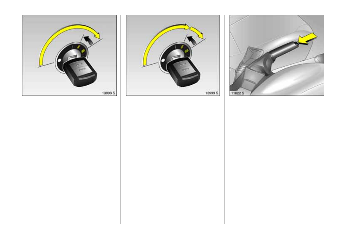
Re mote contr ol b att ery re p lac em ent
Replace the battery as soon as the range
of the radio remote control begins to
shrink.
Separate the key part from the radio
remote control using a screwdriver as
illustrated.
The trans ponder for the immobiliser is in
the front of the key. Make sure that it is not
dam aged or detache d.
Position screwdriver and open remote
control by making a gentle rotary
moveme nt – see figure abov e.
Open the remote control. Prise out battery
with screwdriver. Replace b attery (battery
type – see page 247), ensuring that it is
inserted correctly. Close the remote control
and audibly engage . Insert the remote
control in the key part and engage.
Battery replacement must be performe d
within 3 minutes. Otherwise the remote
control will have to be re synchronised – see
ne x t c o l u mn .
Make sure that you dispose of old batteries
in accordance with environmental
protection regulations.
Remote cont rol synchronisation
If functionality is lost, synchronise the radio
remote control:
1. Switch on ignition; system will then
remain in synchronizing mode for
30 seconds.
2. Briefly press button p or q on the radio
remote c ontro l unit with the unit inserte d
in the ignition.
3. The ce ntral locking system locks and
unlocks to show that the remote control
ha s b ee n sy nch r o n ized .
53
Page 56

Cen tr al l oc king sy stem 3
for doors, sliding d oors, luggage
compartme nt and tank flap 3.
Locking
Press button p on the radio rem ote control
– or –
Push the lock button on the driver’s door
wh en t h e d oors ar e clo s ed.
54
Securing wi th the mechan ica l anti-t heft
locking syste m 3
All doors must be closed. The driver’ s door
mu st hav e be en o pe n ed after the ig nit ion
wa s switc h ed o n . Wit h in 1 0 s econ ds o f
lock ing, press button p on the radio
remote control ag ain
Lock buttons on all doors are positioned
such that doors cannot be opened.
Do not use the system if there are people
in the vehicle! Th e d oors cannot b e
unloc ked from inside.
To unlock
Press button q on the radio remote control
– or –
Pull lock button on driver’ s door.
When the mechanical anti-theft lock ing
system 3 is enabled, the doors cannot be
unlocked by pulling up the lock buttons.
Page 57

Note
z To prevent the driver from being
inad vertently locked out, the button on
the driver’s door cannot be depressed
when the door is open.
z If the driver’s door is not closed properly ,
the ce ntral lock ing system will unlock
again immediately after locking.
z 30 seconds after unlocking using the
ra di o rem o te co n tro l th e d o or s lo ck
again automatically if no door is
op en ed.
z To lock the doors from inside (e.g. to
prevent unwanted entry from outside),
push down lock button on driver’s door.
z L ocked doors unloc k automatically if an
accident of a certain seve rity occu rs (to
permit outside assistance).
Prerequisite: Ignition must not be
switched off.
z In the Combo the central lock ing will
unloc k a gain imme diately a fter locking if
the sliding door is ope n. The doors lock
again a utomatica lly when the sliding
door is closed.
Overload
If the central locking system is overloaded
as a re sult of repeated ope ration at short
intervals, the power supply is briefly cut off.
Th e syste m is p r o t ec t e d by a f u se in t h e
fuse box – see page 1 88.
55
Page 58

Lock in g
With driver’s door closed, turn key towards
rear of ve hicle until it will not move any
further. Turn key back to vertical position
and rem ove.
If the central locking system is not
functional, the other doors can be
unlocked or locked by pulling or pushing
the interior door lock (only pos sib le if the
anti-theft lock ing sy stem 3 is not active).
Have the cause of the fault rem edied. We
recommend that you consult your Vauxhall
Authorised Repairer.
Operating door locks using the key in
the driver’s door lock
To unlock
Turn key in lock toward front of vehicle as
far as it will go. Turn k ey back to vertical
position and re move .
56
Sliding doors 3, Combo
To open sliding doors, pull handle towards
rear of vehicle.
To prev ent damage, the right-hand sliding
door c annot be fully opened if the tank flap
is open.
If th e v ehi cl e is pa rked fa cing down a
slope, open sliding doors may shut
accidentally on account of their weig ht.
Before driv ing off, check that the sliding
doors are properly closed.
Page 59

Luggage compartment
Locking
Turn key to vertica l position.
To unlock
Turn key to horizontal position.
The lock is released by pressing the button.
Using th e central lock ing system with the
luggag e compart me nt
The luggage compartme nt lock cannot be
used to lock or unlock the central locking
sy st e m o r t h e a nti- t h eft locki n g syste m 3.
When unlocked, ope n the luggag e
compartment by pressing the b utton.
Key slot in lock in horizontal p osition
The luggage compartme nt is locked and
unlocked using the central locking syste m.
If the key is turned to the horizontal
position after unlocking via the central
lock ing system, the luggage com partment
remains locked.
Key slot in lock in vertical position
The luggage compartme nt also remains
locked whe n unlocking via the central
locking system . Choos e this position if the
luggage compa rtm ent is to alway s be
locked. Turn the key anticlockwise past the
resistance point as far as it w ill go.
57
Page 60

Unlock ing lugg age comp artment w hen
doors are lock ed via ce ntral loc king
system
Turn key clockwise as far as possible
beyond the resistance from the vertical or
horiz ontal position. Key cannot be
withdrawn to s afeguard a gainst be ing
locked out.
58
Relock the luggage compartme nt by
closing it and turning the key to the
horizontal or vertical position.
In the horizontal position, the luggage
compartment will be unlocked the next
tim e the vehicle is unlocked via the central
lock ing system.
Tail gate, Combo
Open right-hand door from outside by
raising door handle or from inside by
pressing handle.
Release left-hand door from inside by
pressing handle.
The doors are arrested at a 90° angle. To
close, p u sh the doo rs be yon d th e sli ght
resistance.
Page 61

Both doors c an be opened up to 180°:
Close the door slightly from the 90°
position, disengage the stop lug from the
guide rail and open the door comple tely.
If the rear doors are opened up to 180°, the
rear exterior lights are no longer visible.
When driving in the dark, therefore, do not
open the rear doors beyond the point at
which they lock into position.
When clo s ing, make s u re th at the stop lu g
properly engag es in the guide rail.
Note
z The saloon has a handle on the inside of
the ta ilg ate to a ssist closing.
z F itting of acc essories on the tailga te will
increase its w eight. If it become s too
heavy, it will then not stay ope n.
z The registration plate can only b e clearly
seen if the tailgate is closed. It is
therefore not permitted to d riv e with the
tailgate open.
Do not drive with the luggag e
compartm ent open when transporting
bulky goods, since poisonous exhaust
fumes can penetrate the interior d ue to
air turbulence.
59
Page 62

Vauxhall alarm system 3
monitors
z doors, luggag e com partment, bonnet,
z the passenger c ompartment,
z vehicle tilt, e.g. if it is rais ed,
z th e i g n it ion .
60
To activate
All doors, windows, sun roof 3 and bonnet
mu st b e clos ed. P res s button p on the
remote control ag ain within 10 seconds of
lock ing.
Sw itching sy stem on excludin g
monitoring of the passenger
com partm ent and the vehicle tilt
e.g. if animals are to be le ft in the ve hic le.
1. Close luggage comp artment and
bonnet.
2. Press button in front of the c ourtesy light
(with ig nition off); LED in the hazard
warning light button flashes a maximum
of 10 seconds.
3. Close doors.
4. Switch on Vauxhall alarm s ystem . LED
lights up. After approx. 10 sec onds the
system is activated, without monitoring
of the p ass en ger compa rtm ent or vehicle
tilt. The LED flashes until the system is
switched off.
Page 63

After the first 10 seconds of Vauxhall alarm
sy st e m acti vatio n:
z LED flashes = System on,
z LED lights up for
approx . 1 s econd = Switch-off.
If a system fault occurs, consult a
work shop. We recommend your Vauxhall
Authorised Repairer.
Light e mit ting d iode (LED)
During the first 10 seconds of Vauxhall
alarm system activation:
z LED lights up = Test, switch-on
delay,
z LED flashes = Door, tailgate,
bonnet open
or system error,
To deactivate
Press button q on remote control.
If there is a fault in radio remote control,
turn key in driver’s door lock toward front
of vehicle as far as it will go. Then turn key
bac k to vertical position and re move .
If the alarm is triggered when the driver’s
door is opened, deactivate the alarm by
switching on the ignition.
61
Page 64

Openi ng and cl osing tailg ate wit h
Vauxha ll alarm system activated
1. To unlock: Turn key clockwise as far as
possible. Luggag e com partment is
unlocked and m onitoring of the interior
and ve hicle tilt is disabled.
2. Open luggage compartment.
3. C lose lug gage compartme nt.
4. L ocking: Turn key back to previous
position. Monitoring of the interior and
the vehicle tilt is enabled again after
approx . 10 second s.
Alarm
On ly a ce rtain number of a la rm s are
allowed to be triggered while the Vauxhall
alarm system is switched on (this number is
stipula ted b y law).
The alarm take s the form of
z an acoustic signal (horn) a nd
z a visual s ig nal (hazard warning lights).
The duration of the alarm signals is limited
due to lega l regulations.
Alarm c an be cancelled by pressing a
button on the radio remote control. The
anti-theft warning system is switched off at
the sam e time by pressing the button q.
62
Page 65

Bonnet
To open the bonnet, pull the release lever
located on the driver’s side below the
instrument panel. The bonnet will then be
unlocked and will partially open. Return
release lever to its original position.
To op en completely, locate safety catch
approximately a ha nd’ s width to the right
of centre as viewed from the front: lift this
upwards and open bonnet.
Any dirt or snow on the bonnet can slide
down towards the windscreen when the
bonnet is ope ned and block the air intake –
see page 124.
To hold the bonnet in the open position,
insert the support rod located at right
angles above the radiator grille into the
small slot in the underside of the bonnet.
Before closing bonnet, pre ss support rod
firmly into its retaine r. Lower the bonnet
gradually and then allow it to fall into the
lock under its own weight.
Check that the bonnet is locked in position
by pulling at its front edge. If it is not
engaged, repeat the procedure.
63
Page 66

Seats, Interior
Seat adjustment
see page 5 .
64
Se at p osit ion
Ad just driver’s seat such that with the
driver sitting upright the steering wheel is
he ld in the area of its upper spokes with the
driver’s arms slightly bent.
The seat b ackrests must not be tilted too
fa r back (recommend ed tilting angle
approx. 25°).
Disregard can lead to injuries which
could be fatal. Ve hicle passengers
should b e informed accordingly.
Head restraint position
The centre of the head restraint should be
at eye level. Adjust to highest position if
this is not possible for e xtremely tall
people, and adjust to lowest position for
extrem ely small people.
Disregard can lead to injuries which
could be fatal. Vehicle passe ngers
should be informed ac cordingly.
Setting – se e page 6 and the next page.
Page 67

Head restraints
Adjustment – see pag e 6.
To remov e head restraints, release both
springs by pressing and detach head
restraint.
The rear, centre head restraint 3 in the
Com bo cannot be removed.
Rear head restraints 3, Corsa
In order to im prove vision when rear seats
are uno ccupie d, push h ead restr aints as far
do wn as po ss i b le. Pu sh de t en t s p r in gs to
re l ea s e .
If the rear seats are occupied, adjust the
re ar head re straints to the o ccupants’ body
siz e – se e p age 6.
To increase luggage comp artm ent size –
see page 66, removing re ar head
re s t ra in t s 3: Push both detent springs to
release, remove head restraint.
Rear, cent re head restra int 3, Combo
The head re straint can b e push ed right
down to improve visibility if the centre rear
seat is unoccupied or to allow the rear seat
bac krests to be folded down. To d o so,
release both springs by p ressing.
If the centre seat is oc cupied, set the head
restraint to the first or second position
acc ording to the height of the passenger.
65
Page 68

Extending the luggage
compartment, Corsa
Cha nging angl e of rear seat back rest
Release one-piece rea r seat back re st or
split rear set backrests 3 u sin g ha ndle s an d
tilt forward a little.
The rear seat backrests can be locked in
two positions.
66
Folding down t he rear seat back rests
Slot the latch plates of the seat belts in the
holde rs 3 in the side trim cover.
Removing rear head restraints 3 – push
detent springs to release – see page 65.
Remove the push-in sleeves for mounting
the ISO-FIX child restraint system; see the
accompanying instructions for the ISO-FIX
child restraint system .
Unlock the single-piece rear seat back rest
or split rear seat backrests 3 b y pulling on
the handles and fold it/them down onto the
rear seat.
Page 69

– or –
Slot the latch plates of the seat belts in
the holders in the sid e trim cov er –
see Fig. 11585 S on previous page.
Removing rear head restraints 3 – push
detent springs to release – see page 65.
Remove the push-in sleeves for mounting
th e I SO-F IX ch ild r e stra int s ystem; se e the
accomp anying instructions for the IS O-FIX
child re straint system.
Raise front edge of single-piece ba ckrest or
split backre st 3 and tilt forward.
Unlock the single-piece rear seat backrest
or spli t r e ar se a t bac kres t s 3 by pulling on
the handles an d tilt it/them forwards.
Repositioning the rear seats
After repositioning, audibly engage the
bac krest in the intermediate position or full
upright position. There is a lock indicator 3
on th e handles. If the backrest is properly
engaged, th e red field 3 will not be visible
on the handle.
Fold the rear seat d own and push it into
place between the backrest and the vehicle
floor. Press on the front edge of the rear
seat to lock it audibly into place.
Refit the head restraints 3 .
The three-point seat belt on the ce ntre rear
seat can only be pulled out of th e
retractor 3 if the re ar s eat b ackrest is
engaged.
67
Page 70

Removing lugga ge compa rtment cov er
To remov e, unhook the retaining strap s
from the ta ilgate.
Re move the cove r from the side guide s and
place it behind the seat backrests.
Fit in reverse order.
Note s on load ing
see page 7 4.
68
Luggage compartment extension,
Combo
Folding down t he rear seat back rests
Remove rear, outer head restraints 3. Push
detent springs to release, se e page 65.
Push rear, centre head restraint 3 down as
fa r as possible. Push de tent s prings to
release – see page 65.
Remove the push-in sleeves for mounting
the ISO-FIX child restraint system; see the
accompanying instructions for the ISO-FIX
child restraint system .
Unlock one single-piece rear seat backrest
or both using pushbuttons and fold down
onto re ar seat.
– Or –
Remove rear, oute r head restraints 3. Pu sh
detent springs to re lease – see pag e 65.
Push rear, centre head restraint 3 down as
far as possible. Push detent springs to
release – see page 65.
Hook seat belt buckles on rear seat
bac krests.
Re move th e push -in sle eves for m o unting
th e ISO-FIX ch ild r e stra int s ystem; see the
acc ompanying instructions for the ISO-FIX
child re straint system.
Pull u p one or bo th re ar seat cushion s using
straps provided.
Page 71

Repositioning the rear seats
Engage rear seat back re st audibly in
position.
Push back rear seat cushions.
Insert outer rear head restraints 3.
The thre e-point s eat belt o n the centre rear
seat can only be pulled out of the
retractor 3 if the rear s ea t backre st is
engaged.
Disengage one or both rear seat backrests
using the pushbuttons and fold down.
Folding d own the front pa sse nger seat 3
Push p assenger seat head restraint down
and re move – se e pa ge 65.
Tilt passenger seat backrest forward by
lifting the release lever.
To move upright, pus h release lever
forwards and audibly latch front
passenger seat backrest.
Not es on load ing
see page 7 4.
Lash ing eyes 3
The lashing e yes in the luggage
compartm ent are for securing transporte d
items to prevent them from slipping
around.
69
Page 72

Fitti ng
Push le ft side of cover into retainers,
followed by right side.
Push b utton at right e nd piece of cover,
and c over engages.
Luggage compartment cover 3,
Combo
To close
Pull cover towa rds rear of vehicle using
handle and hook into side retainers.
Do not place any heavy or sharp-edged
objects on the cover.
To open
Unhook cover. It reels in automatically.
70
Removing
Ope n cove r.
Pre ss button at right s ide of cov er and
engage by pushing right-hand end p iece
to the left. Pull right s ide of cover out of
retainers, followed by left side.
Page 73

Safety net 3, Com bo
The safety net ca n be fitted behind the rear
seats or, with the re ar seat backre st folde d
down, behind the front seats.
Passengers m ust not be carried behind the
safety net.
There are two installation openings in the
roof frame: Open cover. Sus pend upper net
rod at one side and engage in position. Pull
net rod apart, suspend at oth er side and
engage in p osition. Close cov er.
Fitting behind t he rear seats
Fold down both rear seat backrests, hook
tensioning stra ps into lashing eyes in
vehicle floor and tighten them. Reposition
rear seat backrests and lock the m into
position.
Fitti ng behind front se ats
Pull up both re ar seat cush ions. Fold down
rear seat backrests. Hook tensioning straps
into las hing eye s in vehicle floor a nd
tighten them.
Remov ing
Swivel tensioning strap length adjusters
upward and unhook straps. Open the
cover. Unhook upper net rod and close
cover.
71
Page 74

Load compartment grille 3, C om bo
A load c ompartment g rille is provided
be hi n d th e f r o nt se a t s to pr eve n t t he
vehic le occupants from being injured by
loose cargo.
Sp lit load co mp artment g rille 3
To enlarge the load compartment, the
grille can be moved forwards on the front
pas se n ger’s side.
Push head restraint on front pa ssenger’s
seat down as far as it will go – see page 65.
Til t f r o nt p ass eng e r’s seat b a c kres t
forward by raising release lever and p ush
down to lock in position.
72
Engage lever on load c ompartment g rille
at top pos ition, as shown in illustration.
Engaging the lever prevents dama ge to
the front passenge r’s s eat.
Position load compartme nt grille above
retai n er in fron t pas seng er’s se at b a ckr e st.
Lock load compartment grille in retainer.
To do so, engage lever at bottom position,
as shown in illustration.
The load c om partment grille must
always be locked in one of the retainers
wh en t h e vehicle is in us e, and the leve r
must be engaged at its bottom position.
Not es on load ing
see page 7 4.
Lash ing eyes 3
Lashing eyes are provid ed in the load
compa rtment s o th at cargo can be secur ed
to pre vent it from slipping.
Page 75

Stowage compartment above front
seats, Co mbo
The compartme nt is only suitable for
stowing light objects. Maximum load:
15 kg.
Secure objects to prevent them from
falling out a nd causing injury.
Bag ha ng ers 3
On the back of the rear seat backrest there
are two fixtures on which carrier bags can
be hung. Maximum load: 10 kg.
Stowage compartmen t 3 beneath
passenge r se at
Lift tray by grasping recessed edge and
pull forwards. Maximum load: 1 kg. To
close the tray push it in and lock it in place.
73
Page 76

Notes on loading the vehicle
z Heavy objec ts in the luggage/load
com partment should be placed as far
forward as possible against the rear seat
backrests or, if the rear seat backrests
are folded down, ag ainst the front s eat
backrests. If objects are to be stacked,
the heavier obje cts should be placed at
the bottom. Unsecured objects in the
lugga ge/load compartm ent would be
thrown forward with great force, for
instance in the event of heavy brak ing.
z Secure heavy objects with lashing
straps 3 a ttac he d to lashing eyes 3 –
see page 72. If heavy loads slip when the
vehicle is braked h eavily or driven
around a bend, the handling of the
vehicle may change.
z C om bo: If objects are transported in the
load c ompartment, the split load
compa rtment grille 3 mu s t always be
locked in one of the retainers and the
lever m ust be engaged at its bottom
position – see page 72.
z C ombo : Close th e lu ggage co mpartmen t
cover so there is no reflection in the rear
window.
z If objects are being tran sporte d in the
luggage/load compartment, the rear
s ea t backre sts mu st be lo cked i n p o si t i o n
– see pages 67, 69.
z Do not a llow the load to protrude ab ove
the upp er e dge of the rear seat
backrests, or above the uppe r ed ge of
the front seat backrests if the rear seat
backrests are folded down.
z The warning triangle 3 and first-aid kit
(cushion) 3 must always be freely
acces sible.
z Do not place any obje cts in front of the
rea r window or on the instrument panel.
Th ey are reflecte d in the gla ss , o bstru ct
the driver’s view and will be thrown
th r o ugh th e ve hicle , fo r i n sta nce in th e
event of he avy bra king.
z C om bo: when stowing objects in the
stowage compartment above the front
seats, secure against falling out.
z No objects must be placed in the area in
which the airbags inflate, as they could
cause injury when the airbags are
trig gered.
z The load must not obstruct the operation
of the hand brak e and the gears or
restrict the driver’s freedom of
movement.
z Do not drive with luggage compartm ent
open when tra nsporting bulky objects,
for exam ple, since toxic exhaust fumes
could penetra te the interior.
z Weights, payload and roof load – se e
page 234.
z Driv ing with a roof load (see pages 138,
141, 160) increases the sensitivity of the
vehicle to crosswinds and has a
detrimenta l effec t on vehicle handling
owing to the vehicle’s higher centre of
gravity.
Disregarding instructions can lead to
injuries which cou ld be fatal. Vehicle
pa s seng ers sh ou ld be in f or m ed
accordingly.
74
Page 77

The maximum power c onsumption of
electrical ac cessorie s must not ex ceed
120 watts.
Do not connect any current-delivering
acc essories, e.g. electrical charging
devices or batteries.
Electrical ac cessorie s connected to the
socket must comply with the
electromagnetic compatibility
require me nts la id d ow n in DIN VDE 40 839,
otherwise vehicle malfunctions may occur.
Cigarette lighter ) 3
In front centre console
Press in cigarette lighter with ignition
switched on. Switches off automatically
wh en e lem ent i s glo win g. Wit h dra w
cigarette lighter.
Accessory socket 3
The acce ssory socke t or cigarette lighter
socket can be used to connect electrical
accessories. The socket is operational
when the ignition is switched on. Use of the
socket discharges the battery if the engine
is not running. Do not damage the socket
by using unsuitable plugs.
75
Page 78

Ashtray 3
To be used only for ash and not for
combus tible rubbish.
Disregard c an lead to injuries which may
be f atal. Vehicle p a ssen ge r s s h o u ld be
informed accordingly.
Front ashtray 3
Open the ashtray cover to the resistance
point.
76
To empty, open the ashtray cover fully
beyond its resistance p oint, causing the
insert to lift. Grip both sides of the ashtra y
insert and pull upwards .
To en large t he storage c om par tmen t
remove the ashtray completely.
Rear a shtray 3
To open, swivel the cover upwards.
To e mpty, lift the cover and pull th e
ashtray out upwards by its cover.
Page 79

Glove c om par tm ent
To open, pull handle upwards.
On the inside of the glove compartment
co ve r th er e is a pen holde r .
In ve hicle s w ith Infotain ment s yste m 3, the
telematics unit 3 can be housed in the
glove compartme nt.
Stowage compartmen t 3 for glasses
On drive r’s sid e: Fold down to o pe n.
Co in holder 3
In the centre console.
Sun visors
Use the sun visor to protect from glare by
pulling it d own and swivelling it to the side .
77
Page 80

Safety systems
Three-stage re straint system
Compris ing:
z Three-point seat belts,
z Be lt tensioners at the front seats,
z Airbag systems for driver’s seat,
passenger seat 3 and outboard rear
seats 3.
The thre e stages are a ctivated in se quence
depending on the seriousness of the
accident:
z The automatic seat belt locking de vices
prevent the belt strap from being pulled
out and thus ensure that the vehicle
occupants are re tained in their seats .
z The front seat b elt buckle s are pulled
downwards. As a result, the seat belts
are instantaneously tightened and the
occupants are made aware of the
deceleration of the vehicle at a very early
stage. This reduces the stress placed on
the body.
z The airbag systems a re also triggered in
th e ev en t of s eri ou s ac cid e nt s an d f o rm a
safety cushion for the occupants.
The a irbag syste m s 3 serve to
supplement the three-point seat belts
and belt tensione rs. The seat belts must
therefore always be worn. Disregard of
these instructions may lead to injuries or
en dan g e r li fe. Ve hi cl e p ass en ge r s sho u ld
be informed accordingly.
Be sure to read the a ccompanying
desc ription of the child restraint system !
78
Page 81

Seat belts
Alwa ys wear your seat belt, and that
means also in urb an traffic and when
you are a rear seat pas senger. It can
save y our life!
Pregnant women must always wear a
seat belt – see page 8 2.
In the event of an accident, persons not
wearing sea t belts e ndanger their fe llow
occupants and themselves.
Warning light X for the seat belt – see
page 29.
Seat belts are designed to be used by only
one person at a time. They are not suitable
for c hildren under 12 yea rs of age or
150 cm un less an appropriate child
restraint system is used.
For children up to 12 y ears of age we
recomme nd the Vauxhall child re straint
sy st e m – se e pa ge 9 5.
Three-point seat belts
The vehicle is equipped with three-point
seat belts with automatic re tractors and
locking d evices, allowing freedom of body
movement although the spring tensioned
be lts alw a y s en su r e a s nug fit. C orre ct se at
position – see page 85.
The belt has a "vehicle s ensitive retra ctor"
which is de signed to lock during heavy
acceleration or deceleration in any
direction.
79
Page 82

Belt tens io ners
Th e fro n t se at belt s are e quipped w ith be lt
tensioners. In the event of a head-on or
rear-end collision of a certain severity, the
buckles are pulle d downwards , thereby
tightening the belts.
If the seat be lts are undama ged the
operation thereof is unaffected, even if the
belt tensioners have b een triggered.
Further information – see page 83.
Actuati on of be lt te nsioners
is indicated by illumination of control
indica tor v, see next page.
The be lt tensioners must be replace d after
activation. We recommend that you
co nsu l t y our Va ux ha l l A u th or i s ed R ep a i r er.
80
Page 83

Cont rol indica tor v for belt t ension ers
The b elt tensioners are monitored
electronically and their operational
readine ss is indicated on the instrumen t
panel by c ontrol indicator v . Wh en the
ignition is switched on the control indicator
lights up for approx. 4 seconds. I f it does
not light up, does not go off after
4 seconds, or lights up wh ile driving, the re
is fault in the belt tensioner system or the
airbag systems – see page 89. The belt
tensioners or airbag systems may not be
triggered in the event of an accident.
Have the cause of the fault remedied .
We recom mend that y ou consult your
Vauxhall Authorised Rep airer.
The system’s integrated self-diagnostics
allow s faults to be quickly remedied. Have
yo ur Car P a s s on ha nd wh en co n s ult i n g a
Vauxhall Authorised Repairer.
Imp or tant
z Do not fit acce ssories not sp ecifically
released for your vehicle type or store
objects in the belt tensioner ope rating
area (in the area of the belt tensioners)
due to the risk of injury in the event the
belt tensioners are triggered.
z Do not mak e any modifications to the
components of the belt tensioners, as
this will render the v ehicle unroadworthy.
Imprope r handling (e.g. removal or
installation) could cause the be lt
tensioners to be triggered. Risk of injury!
z The belt tensioner and airbag system
control electronics can be found in the
centre console area. In order to avoid
malfunctions, do not store magnetic
objects in this are a.
z We recom mend that you have the front
seats removed by a Vauxhall Authorised
Repairer.
z The belt tensioners only actuate once.
Ple ase replace belt tensioners that have
been triggered. We recom mend that you
consult your Vauxhall Authorised
Repairer.
z Applicable safety directives must always
be ob served when dis p osin g of the
vehicle. For this reason, d isposal should
be performed by an authorised re cycling
company. We re commend that you
consult your Vauxhall Authorised
Repairer.
81
Page 84

Usin g t he b elts
Fitting seat belts
Pull the belt out of the retractor and guide
it across the body, making ce rtain that it is
not twisted.
Insert latch plate into buckle. Backre st
must not be tilted too far back as this
would affect the opera tion of the seat
belts; recommended tilting a ngle app rox.
25°. The lap belt must be s traight and lie
snugly against the body. Tighten lap belt
at frequent intervals whilst driving by
tugging diagonal pa rt of belt.
82
On pregnant women in particular, the
lap belt must be positioned as low as
possible ac ross the pelv is so as not to put
too much pressure on the abdomen.
Bulk y clothing prevents the belt from fitting
properly. The belt must not rest against
ha rd or fragile objects in the pockets of
you r clothing (e.g. ballpoint pens, ke ys ,
spectacles) be cause these could cause
injury. Do not place any objec ts (e.g.
ha ndbags, mobile phones) between the
belt and your body.
Height adjustment
of front seat belt upper a nchorage points:
1. Pull belt out slig htly.
2. Press belt guide or, in 5-door saloon,
push button down.
3. Se t desired heigh t.
4. Allow to lock audibly into p osition.
Do not adjust height while driving.
Adjust height setting such that seat belt
runs over and lies against the shoulder. The
belt must not run over the neck or upper
arm – see page 79, F ig. 13190 S.
Page 85

Remov ing the belt
To rem ove the be lt, depress the red
pushbutton on the buckle ; the belt will
retract automatically.
Three -point seat b elt on centre rear seat
The be lt can only be pulled out of the
retractor 3 if the rear seat backrests are
engaged in their retainers – see page 67.
Testing the belts
Plea se c h eck a ll par ts of th e b elt s ys t em
occasionally for dama ge a nd correct
operation. Have damage d parts replaced .
In ca se of an accide nt, please replace
overstretched belts and triggered belt
tensioners. We recommend consulting your
Vauxhall Authorised Repairer.
Do not perform any altera tions on the
belts, their anchorages, the automatic
retractors or the belt buck les.
Mak e sure that b elts are not da mage d or
trapped by sharp-edge d objects.
83
Page 86

Vauxhall Full Size airbag system
Front airb ag
Th e fro nt a irbag s ys t em is iden tified by th e
word AIRBAG on th e s teering whee l an d
above the glove compartment 3.
The front airbag system comprises:
z an airbag with inflator in the steering
wheel and a second one in the
instrument panel 3,
z the control elec tronics with impact
se ns or ,
z the airbag systems control indicator v in
the instrument panel.
z seat occ upancy rec ognition 3,
z the control indicator for Vauxhall child
restraint systems y with transponders 3
in the courtesy light.
The front airb ag system will be triggered:
z depending on the severity of the
accident,
z de pending on the type of impact,
z within the range shown in the illustration,
z independently of the side airb ag
system 3 and curtain airbag system 3.
Exception:
Passenger sea t with seat occupancy
recognition syste m 3 . The seat occupancy
recognition system deactiva tes the
passenger front and side airbags if the
passenger seat is unoccupied or a
Vauxhall child restraint s ystem with
transponders 3 has be en fitted to the
passenger seat. Seat occupa ncy
recognition – see p age 89. Vauxhall child
re st r aint sy ste m w i th t r an spo n d e rs 3 – s ee
pag e 96.
Examples of events triggering the front
airbag system:
z Impact against a non-yielding obstacle:
The front airbags are trigg ered at low
vehicle speed.
z Impact against a yield ing obstacle
(such as another vehicle): The front
airbags are only triggered at a higher
vehicle speed.
84
Page 87

When trigg ered, the front airbags inflate in
milliseconds and form a safety cushion for
driver an d front pas senger. The forward
movement of the driver and front
passenger is che cked and the risk of
injuries to the upper body a nd head
thereby substantially reduced.
No im pairment of view will occur, because
the a irbags inflate and deflate so quickly
that it is often not even noticed in an
accident.
The front airbag system provides
optimum protection when the seat,
backrest and head restraint are corre ctly
adju s ted: Adj ust the dr iver’s seat
according to the occupant’s height so
that whe n the driver is sitting up right, the
steering wheel is held in the area of its
uppe r sp ok es wit h the d riv er’s arms
slightly bent. The passenger seat shou ld
be as far back as possible, with the
backrest upright (see pages 5, 64, 82).
Do not place the head, body, hands or
feet on the covers of the airbag systems.
Do not place any objects in the area in
which the airb ags inflate. Important
information – s ee page 92.
Th e thr e e-poin t s eat be lt must b e
correctly fitted – see page 82.
The front airbag system will not be
triggered in the event of
z the ignition is switched off,
z minor frontal collisions,
z accidents in which the vehicle overturns,
z collisions involving a side or rear impa ct,
that is to say, if it w ould not be of benefit to
the occupants.
85
Page 88

Seat belts must therefore always be
worn. The front airbag system serves to
supplement the three-point seat belts. If
you do not wea r your seat be lt you r is k
being seriously injure d, or even thrown
from the ve hic le, in th e event o f an
accident.
In the event of an accident the belt he lps
to keep you in the correct seating
position, so that the front airbag s ystem
can pr o vide you wit h ef fe cti ve
protection.
In addition, the front airb ag system will not
be triggered for the front passenger in
versions with seat occupancy recognition 3
if
z the front passenger’s seat is unoccupied,
z the re is a prop erly fitted Vauxha ll child
restraint system with transponders 3 .
Seat occup ancy recognition, see
page 89. Vauxhall child restraint system
w i th tr a n s p o n d e r s 3 – see page 96.
Side airb ag 3
The side airbag system is identified by the
word AIRBAG on the outb oard sides of the
front seat backrests.
The side airbag system comprises:
z An airbag with inflator in the back of the
driver’s and front passenger’s s eat
respectively ,
z T h e cont rol elect ronics,
z T h e sid e imp a ct se n sors,
z The airbag systems control indicator v
in the instrument pane l,
z Seat occupancy recognition 3,
z The control indicator for Vauxhall child
restraint systems y with transponders 3
in the courtesy light.
The side airbag system will be trigge red:
z Depending on the severity of the
accident,
z Depending on the type of impa ct,
z Within the range sh own in the illus tra tion
on the centre d oor pillar of the driver’s or
front passenger side,
z Independently of the front a irba g
sy ste m.
Exce ption: Pa ssenger seat with seat
occupancy recognition system 3. The seat
occupancy recognition system deactivates
the pa ssenger front and side airbags if the
passenger seat is unoccupied or a
Vauxhall child restraint s ystem with
transponders 3 has be en fitted to the
passenger seat. Seat occupa ncy
recognition – see p age 89. Vauxhall child
restraint system w ith transponders 3
– se e page 96.
86
Page 89

When triggere d, the side airbag inflates in
milliseconds to form a safety cushion for
th e d riv er or f r o n t pas se n ger in the
respective door area. This substantially
reduces the risk of injury to the upper body
in the event of a side-on collision.
There must be no objects in the area in
which the airbag inflates or in the a rea
between the seat backs and the ve hicle
body. Do not place the hands or arms on
the covers of the airbag systems.
Important information – see page 92.
Th e thre e-p oint se at b elt m us t always b e
correctly fitted – see page 82.
The side airbags will not be triggered in the
eve n t o f
z the ignition is switched off,
z fronta l collisions,
z accidents in which the vehicle overturns,
z collisions involving a re ar impac t,
z collisions involving a side imp act outside
the passenger cell.
In addition, the side airbag system will not
be triggered for the front passenger in
versions with seat occupa ncy recognition 3
if
z the front p assenger’s seat is unoccupied
z there is a prope rly fitted Vauxhall child
restraint system with transponders 3.
Seat occupancy recognition, see
page 8 9. Vauxhall c hild restraint system
with transponders 3 – see page 96.
Curtain ai rbag 3
The curtain airbag system is identified by
the word AIRBAG on the roof pillar trim.
The curtain a irbag system comprises:
z an airbag w ith inflator in the roof frame
on the d river’s and front passenger’s side
respectively,
z the control electronics,
z the side impact sensors,
z the airb ag systems control indicator v in
the instrument panel.
87
Page 90

The curtain airbag s ystem will be trigge red:
z Depending on the severity of the
accident,
z Depending on the type of impac t,
z Within the range sh ow n in the illustration
on the centre door pillar of the driver’s or
front passenger side,
z Toge ther with the side airbag system,
z Irrespective of seat occupancy
recognition,
z Ind ependently of the front airbag
sys tem .
When triggered, the curtain airbag inflates
in milliseconds to form a safety cushion in
the head area on the side of the vehicle
affected. This substantially reduces the risk
of injury to the head in the event of a sideon c ollision.
The re m u st be no obj ec ts i n the area i n
which the airbag inflates. Do not place
the hands or arms on the covers of the
airbag systems. Important information –
see page 92.
The thre e-point s eat be lt mu st alway s be
correctly fitted – see page 82.
The curtain airbags will not be triggered in
th e eve n t of
z the ignition is switched off,
z frontal collis ions,
z accidents in which the vehicle overturns,
z collisions involving a rear impact,
z collisions involving a side impact outside
the passenger cell.
88
Page 91

Cont rol indica tor v for airb ag systems
The airbag systems are monitored
electronic ally together with seat
occupancy recognition 3 and the belt
tensioners. Their ope rational readiness is
shown by control indicator v in th e
instrument panel. When the ignition is
switched on, the control indicator lights up
for approx. 4 seconds. If it does not light
up, does not go out after 4 seconds or
lights up while driving, there is a fault in the
airbag systems, seat occu pancy
recognition 3 or the belt tensioners – see
page 8 1. The systems may fail to trigg er in
the event of an accident.
Have the cause of the fault remedied.
We recommend that you consult your
Vauxhall Authorised Repairer.
The system’s integrated self-diagnostics
allow s faults to be quickly remedied. Have
yo ur Car P a s s on ha nd wh en co n s ult i n g a
Vauxhall Authorised Repairer.
Seat occup ancy recognition 3
The s eat occupa ncy recognition system
deactiv ates the front and side passenger
airbags if the front passenger seat is
unoccupied or a Vauxhall child restraint
sy st e m wi th tr an s p on d er s 3 has be en fitte d
to the front passe nger seat. The curtain
airbag system remains activated.
The control indicator for sea t occupancy
recognition is locate d in the courtesy light.
If this control indicator lights up afte r the
ignition is switched on for approx.
4 seconds, the vehicle is equipped with
seat occupancy recognition – s ee
Fig. 12097 S on page 90.
If a Vauxhall child restraint s ystem w ith
tra nsponders 3 is installed, this control
indicator remains on after the ignition has
been switched on as soon as the system
ha s detec ted the se at. Only then c an the
child restraint system be used on the
passenger seat.
In ad dition, vehicles with seat occupancy
recognition can be id entified by the sticker
on the front passenger seat.
Vauxhall child restraint s ystems with
transponders 3 are automatically
detected if correctly fitted to the front
passenger seat. When these child restraint
systems are being used on the front
passenger seat, the front and side airbag
sys tems for t h e fron t passe n ger seat are
deactivated. The curtain a irbag system
remains activated. Pay attention to the
seat occupancy re cognition 3 control
indicator – see page 90.
6
89
Page 92

Warnin g lig ht y for Vauxhall
child restraint systems with
trans ponders 3
The presence of an Vauxhall child restraint
sy st e m with transpon de rs 3 is ind icated
after the ignition has been switched on by
permanent illum ination of the c ontrol
indica tor y in the courtesy light, as soon
as the seat occupa ncy recognition system
ha s d et ec ted the chil d r es trai n t sy ste m.
Only Vauxhall child re straint systems
with transponders 3 can be fitte d on the
front passenger seat; the use of systems
without transponde rs poses a danger to
li f e .
Vauxhall child restraint systems with
transponders 3 are iden t ified by a sticke r.
90
If the control indicator d oes not illuminate
whilst driving, the front and side airbag
have not been deactivated on the
passenger side. Risk of fatal injury to the
child – fit child restraint system to rear seat.
Hav e c aus e of f a ult re me di ed . W e
recommend that you consult y our Vauxhall
Authorised Repairer.
If a child restraint system is incorrectly
fitted or the transponders are faulty, the
control indicator will flash. Check that child
restraint system has been fitted correctly.
Fitting child restraint system with
transponders 3 – see page 96.
Page 93

If the control indicator doe s not illuminate
with a c orrectly installed child re straint
system there is a fault – risk of fatal injury
to the child. Fit child restra int system to
rear seat. Have cause of fault remedied.
We recommend that you consult your
Vauxhall Authorised Repairer.
If no V auxhall child restraint system with
transponders 3 is installed the control
indicator must neither illuminate nor flash,
since the passenger side airbag systems
would not be trigg ered. Have the c ause of
fault remedied. We recommend that you
consult your Vauxhall Authorised Repairer.
If the Vaux hall child restraint system
with transponders 3 has been fitted
according to the instructions, the control
indicator for Vauxhall restraint system s
with transponders must light up in the
courtesy light whe n the ignition is
switched on.
If the control indicator does not
illuminate whilst driving, the airbag
systems have not been deactivated on
th e pas se nger s id e. Ris k of fatal inju ry. In
this case, fit child restraint system to rear
seat. Have cause of fault remedied. We
recommend that you consult your
Vauxhall Authorised Repairer.
91
Page 94

Im portant
z Accessories and other objects must not
be affixe d or pl aced in the a rea in which
the airbags inflate as they could caus e
injury if the airbags are triggered.
z Do not place any objects between the
airb ag s ystems and the ve hicle
occ upa nts ; d ang er o f i n j ury .
z Use the hooks in the roof frame only to
hang up light articles of clothing or coat
hangers. Do not place any objects in the
pockets of the hanging items – risk of
in j u r y.
z The airbag system s and belt tensioner
control e lectronics can be found in the
centre console area. In order to avoid
malfunctions, do not store magn etic
ob je cts in this are a.
z Do no t s t i c k a ny thin g o n t h e ste eri n g
wheel, instrument p anel, front seat
backrests or roof fram e in the vicinity of
the airbags, or on the front pa ssenger’s
seat cushion, or cover any of those areas
wi th ot h e r ma t e ri al s .
z Use only a dr y cl ot h o r i nt e rior c l e an er to
clean the steering wheel, instrum ent
panel, front s eat b ackrests, roof fram e
and seat cushion of the front passenger
seat. Do not use any aggressive cleaning
agents.
z O nly protective cove rs whic h are
approved for y our C orsa/Combo w ith
side airbag may be fitted on the front
seats. When fitting the protective co vers,
make sure that the airbag units on the
outboard sides of the front seat
backrests a re not covered.
z The airbag systems are triggered
indep endently of each other depending
on the se verity of the accident and the
type of impa ct. The side airbag system
and the cu rtain airbag system are
triggered together.
z E ach airbag can be triggere d only once.
Once triggered, an airbag must be
replaced without delay. We recomm end
that you consult your Vauxhall
Authorised Repairer.
z T h e s pee ds, d i re c tio n s of m ov em e nt an d
de form ation p rope rties o f the v eh i cl es ,
and the properties of the obstacle
concerned, determine the se verity of the
accident and triggering of the airbags .
The degree of da mage to your vehicle
and the resulting repair cos ts alone are
not indicative that the criteria for
triggering of the airbags were met.
z Do not perform any alterations on the
components of the airbag system, as this
would render the vehicle unroadworthy.
The systems can be triggered abruptly
an d caus e inju r y i f th ey are ha nd le d
improperly.
z We re com men d having t h e s t ee r ing
wheel, the instrument panel, all panelling
parts, the door seals, the handles and
the seats removed by your Vauxhall
Authorised Repairer.
z Applicable safety directives must always
be ob served when dis p osin g of the
vehicle. For this reason, d isposal should
be performed by an authorised re cycling
company. We re commend that you
consult your Vauxhall Authorised
Repairer.
92
Page 95

z Pe rsons weighing le ss than 35 kg should
on l y t ra vel on t h e rear se at s. T hi s d o e s
not ap ply to children who are trav elling
in c hild restraint systems with
tr an s p o n de rs 3.
z In vehicles with seat occupancy
recognition 3, do not plac e any heavy
objects on the front passenger’s seat
otherwise the airbag systems for the
front passenger’s seat may be triggered
in th e ev ent of a n acc id ent .
z In vehicles with seat occupancy
recognition 3, to prevent malfunctions
do n ot us e pro tect ive cove rs or s ea t
cushions on the front passenger’s seat.
z W hen using a Vauxhall child restraint
system with transponders 3 on the front
passenger se at, in order to prevent
malfunctions, no objects (e.g. plastic
sheet, stickers or heated mats) may be
placed under the child restraint system.
Child restraint systems a s well as other
objects must never b e carried on the la p
of passengers; risk of fatal injury. If
carried in this way, c hild restraint
systems with transponders 3 in vehicles
with s eat o ccupancy re cognition 3 co uld
lead to front passenger airbag systems
not being triggered in the event of an
accident.
Use of child restraint systems 3 on front
pa ssenger sea t in ve hicl es wi th airbag
systems 3 bu t wi th out seat occupa ncy
recogn it ion 3
Vehicles with front p assenger airbag 3
without side airbag 3: Child seats facing
the rear of the vehicle must not be
installed on the front passenger sea t, risk
of fatal injury. Child seats facing the
direction of travel (child seats for we ig ht
classe s I, II and III , following pag es) may
be installed on the front p assenger seat
if the seat has been pushed back as far
as it will go and the backrest has been
adjusted such that the lap b elt fits
snugly.
93
6
Page 96

Vehicles with front pas senger airbag can
be identif ied by th e wor d AIRBAG above
the glov e compartment and the warning
sticker on the side of the instrum ent panel,
vis ible when th e p ass en ge r do o r is open .
Vehicles with side airbag 3: N o child
restraint system 3 ma y be fitted on the
front passenger’s sea t; risk of fatal
in j u r y.
94
A vehicle with side airbags can be
identi fied b y th e word AIRBAG on the
outboard sides of the front se at backrests.
Seat occupancy re cogn ition 3 –
see page 89.
Use of child restraint systems 3 on front
pa ssenger sea t in ve hicl es wi th airbag
systems 3 and wi th seat occupa nc y
recogn it ion 3
Only Vauxhall child re straint systems
with transponders 3 should be fitted on
the front passeng er seats. Use of
sy st e ms w i t ho u t t r an s pond ers pose s a
danger to life .
Page 97

Seat occupancy recognition in a vehicle is
indicated by the control indica tor in the
courtesy light. If this control indicator lights
for approx. 4 seconds when the ignition is
switched on, it indicates that the vehicle is
equipped with seat occupancy rec ognition
– see page 89.
Seat occupancy recognition in a vehicle is
also indicated by a sticker on the front
passenger seat – se e page 94,
Fig. 12106 A.
The se at occupancy recognition system
detects Vaux hall child restraint systems
with transponders 3 an d s wit ches off t h e
front and side airbag systems for the front
passenger’s sea t. The curtain airbag
system remains activated. Seat occupancy
recognition – se e pa ge 89.
Vauxhall child restraint systems with
transponders 3 can be identified by the
stic ker on the child restraint system.
Child restraint systems 3
The V auxhall child restraint system is
designed specifically for your V auxhall and
thus provides optimum safety for y our child
in the event of impa ct. If a different child
safety seat is used, follow the
manufac turers’ instructions for fitting a nd
us e.
Selec tin g the rig ht system
Your child should be transported facing
backwards in the car as long as possible. It
is appropria te to change the system when
the child’s head can no longe r be p roperly
supported at eye height. The child’s neck is
still very weak and in an accident they
suffer less stress in the semi-prone
backwards position than w hen sitting
up rig ht .
Not e
z Children under 12 years or under 150 cm
tall should only trav el in an ap prop riate
child safety sea t.
z When transporting children, use the child
restraint system s suitable for the child’s
weight.
z Ensure that the child restraint system is
fitte d correctly.
z The covers of the Vauxhall child restraint
sy st e m can b e wi pe d cl e an .
z Do not stick any thing on the child
restraint systems and do not cover them
with any other materials.
z Only allow children to e nter and exit at
the side facing away from the traffic.
z A child restraint system which has be en
subjected to stress in an accide nt must
be replace d.
z Yo u sh ou l d als o ob se rve the instruction s
on installation and use supplied with the
child restraint system.
95
Page 98

Permissible options for fitting a child safety seat in your Corsa/Combo
Weight
and
age cl ass
0:
up to 10 kg
or approx.
10 months
0+:
up to 13 kg
or approx.
2 years
I:
9 to 18 kg
or approx.
8 months to
4years
II :
15 t o 25 kg
or approx.
3 to 7 years
II I:
22 t o 36 kg
or approx.
6 to 12 years
On
front
passenger seat
B1, ++ U+ U
B1, ++ U+ U
B2, ++ U+ U
B2 U U
B2 U U
On
a rear
outboard seat
On
centre rear
seat
B1 = p rovided: no front passenger airbag
or with seat occupancy recognition
and Vauxhall child restraint system
with
transponders. Front passenger
seat height adjustment also required.
Front passenger seat in highest
position and slid all the way back.
Height adjustment of front passenger
seat belt set to lowest position.
B2 = p rovided: without side airbag,
with front passenger seat slid
all the way back or with
seat occup ancy recog nition and
Vauxhall
child re straint system with
transponders. Front passenge r seat
h ei g ht a dj ust m e nt also r eq u ir ed .
Front passenger seat in highest
position and slid all the way back.
Mak e s u re v ehicle se at be lt
is as straight as possible between
shoulder and de viation point
in vehicle.
U = universally suitable in conjunction with
three-point seat belt.
96
Page 99

+ = seat with ISO-FIX mounting
available. When mounting with
ISO-FIX, only IS O-FIX child restraint
systems that have be en approved for
th e vehicle m ay be us ed .
We recommend that you contact
your Vauxhall Authorised Repairer.
++ = seat with ISO-FIX m ounting available
for Cors a only; only child safety
systems approved for the vehicle
may be u sed
Exterior mirrors
For the safety of pedestrians, the exterior
mirrors will swing out of their normal
mounting position if they are bumped.
Reposition the mirror by applying slight
pressure 3.
Aspherical exterior mirror 3
increases the field of view. Estimating the
distance away of vehicle s following y ou is
only possible to a limited extent b ecause of
slight distortion.
Sport exteri or mi rr ors 3
For the safety of pedestrians, the mirrors
are released from their mountings if they
are bumped with sufficient force.
Relocate the disengaged mirror housing in
its mountings and e ngage by applying
pressure.
97
Page 100

Head restraints
Do not attach objects or com ponents that
are not appro ved fo r your C orsa/Combo to
the head restraints, since they can reduce
the protection prov ided by the head
restraints a nd could be catapulted
uncontrollably through the v ehicle in the
event of hard braking or an accide nt.
Safety access ori es 3
The wide range of Vauxhall a ccessories
allow s you to equip y our Corsa/Combo as
you desire. In addition to safety
accessories, items for improving comfort
and a comp lete range of v ehicle care
products, there are m any articles which will
be of great value to you when needed.
"Genuine Vauxhall Parts and Accessories"
guarantee high q uality and accurate fit.
Yo u r Va ux ha ll A uth o ri se d R e pa i r er w i ll b e
ha ppy to ad vise you, for exam ple w ith
regard to:
z V auxhall child restraint systems,
z Tow ropes,
z Tow rods,
z Ju mp lead s,
z Sp are bu lb kit,
z Sp are fu s e kit ,
z Halogen fog ligh ts,
z Mud flaps,
z Magnetic light,
z W arning tria ngle ,
z First-aid kit,
z First-aid kit (cushion).
98
 Loading...