

Page 1
ASTRA
ASTRA
Operation, Safety and Maintenance
Owner’s Manual
Page 2

VAUXHALL Astr a
Operation, Safety, Maintenance
Page 3

Data s p ecific to your v ehicle
Please enter your vehicle’s data here to keep it easily accessible.
This information is available under the section "Technical data" as well as on the identification plate and in the Service Booklet.
Fuel
Designation
Engine oil
Grade
Viscosity
Tyre pressure
Tyre size for load with 1 person and
light luggage
Summer tyres Front Rear Front Rear
Winter tyres Front Rear Front Rear
with full load
Weights
Permissible gross vehicle weight
– EC kerb weight
=Loading
Page 4

Your Astra
is an intelligent combination of forwardlooking technology, impressive safety,
env ironmental friendliness a nd economy.
It no w li es with you to drive your vehicle
safely and ensur e that it performs
perfectly. T his Owner’s Manual provides
you with all the necessary information to
that end.
Make sure yo ur passengers are aware
ofthe possibl e risk of ac ci dent and injury
which may result from imprope r use of the
vehicle.
You must always comply with the specific
laws of the country that you are travelling
th ro ug h. These laws may differ from the
informatio n in this Owner’s Manual.
When this Manual re fers to a workshop
visit, we re commend your Vauxhall
Authorised Repairer.
A ll Vauxhall Authorised Repairers provide
first class se rvice at reasonable prices.
You will receive quick, reliable and
in dividual service.
Experienced mechanics, trained by
Vauxhall, work according to specific
Vauxhall instructions.
T he Owner’s Man ual should always be kept
in t he vehicle: Rea dy to hand in the glove
compartment.
Make use of the Owner’s Manual:
z The "In Brief" se ctio n will give you an
initial overview.
z The table of contents at the beginning
of the owner’s manual and within the
individual chapters will sho w y o u where
everything is.
z Its index will help you find what you
want.
z It will familiarise you with the
sophisticated technology.
z It will in crease yo ur pleasu re in your
vehicle.
z It will help you to handl e your vehicle
expertly.
T he Owner’s Manual is designed to be
clearly laid out and easily un derstood.
This symbol signifies:
6 Continue read ing on next page.
3 Items marked with an asterisk are not
fitted to all vehicles (model vari ants,
engine options, models specific to one
country , optional equi pment, Genuine
Vauxhall Parts and Accessories).
9 Wa r n ing
Text marked 9 Warnin g provides
in formation on risk of accident or in jury.
Disregard of the in structions may lead to
injuries or endanger life.
Inf orm your passengers accordingly.
Yellow arrows in the illustrations serve as
points of re ference or indicate some ac ti on
to be performed.
Black arrows in the illustrations indicate
a reaction or a second action to be
per f ormed.
Directional data, e.g. left or right, or front
or back, in the descriptions always relate to
the direction of travel.
Thank you for choos ing a Vauxhall. We
wish you many hours of pleasurabl e
driving.
Your Vauxhall Team
Page 5

Contents
Comm itment to c ustomer
satisfaction:
Our aim: to keep you happy with your
vehicle. All Vauxhall Aut horised Repairers
offer first-class service at comp etitive
prices. Experienced, factory-trained
technicians work according to factory
in structions. Your Author ised Repair er can
supply you with GENUINE VA UXHALL-
A PPROVED PARTS, which have undergone
stringent quality and precision checks, and
of course useful and a ttractive
VAUXHALL-APPROVED ACCESSORIES.
Our name is your guarantee!
For details of the
Vauxhall Authorised Repairer Netw ork,
please ring this number; 0845 090 2044
In Brief ....................................................... 2
Keys, Doors, Windows, TwinT op ........... 28
Seats, Interior .......................................... 64
Instruments, Controls ........................... 112
L igh ting ..... .... ..... .... .... ......... ..... .... ..... .... 143
Infotainment system ............................ 151
Climate control .................................... 154
Driving and operation ......................... 176
Self-help, Vehicle care ......................... 241
Service, Maintenance ........................... 294
Technical data .................................... 308
Index ...................................................... 354
Page 6
2In Brief
In B rief
Pict ure no: 16968t. tif
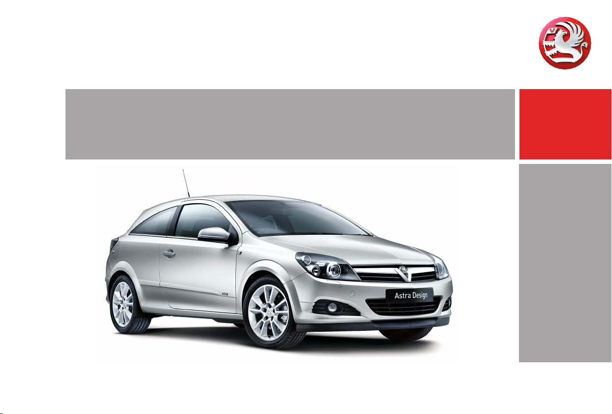
To unlock and open the vehi cle:
Pres s bu tton q,
pull door ha ndle
6 Door l ocks – see page47,
keys – see page 28,
electronic immobiliser – see page29,
radio remote control – see page 30,
central locking – see page 38,
anti-theft prot ectio n 3 – see page 39,
V aux hall alarm sy stem 3 – see page 44,
TwinTop roof operat ion 3 – see page 56.
Pic tur e no: 17333t.t if
To unlock an d open the v ehicle
with the Open&Start System 3:
Bring electronic key into th e
reception area of the vehicle,
pull handle
6 Op en&Sta rt S ystem3 – see page 32.
Page 7
3In Brief
Pict ure no : 16969t.t if
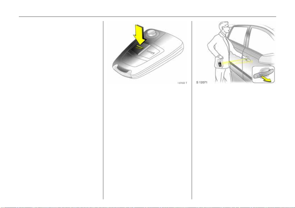
To un l oc k and o pe n th e l uggage
compartme nt:
Press button q on ra dio remo te
contro l, or fo r the
Open&Start System 3:
Bri ng e lectron ic ke y into the
reception a rea of the vehicle,
pull b utton bel ow handle
6 Open&S tart-System 3 – page 32,
Radio remote control – page 30,
Central locking system – page 38,
Vauxhall alarm system 3 – page 44.
Pict ure no: 16970t. tif
To adjust front seat:
Pull handle, slide seat,
release handle
6 Seat – page64, seat position – page 67.
9 Wa r n i n g
Important: Do not sit nearer than 10
inches (25 cm ) from the steering wheel, to
permit safe airbag deplo yment.
Pic tur e no: 16971t.t if
Adju st fr o nt seat bac k r est s:
Turn handw heel
Move backrest to suit seating positi o n .
Do not lean on seat backr est whilst
adjus ting it.
6 Seat – page 64, seat position – page 67.
Page 8
4In Brief
Pict ure no : 16973t.t if
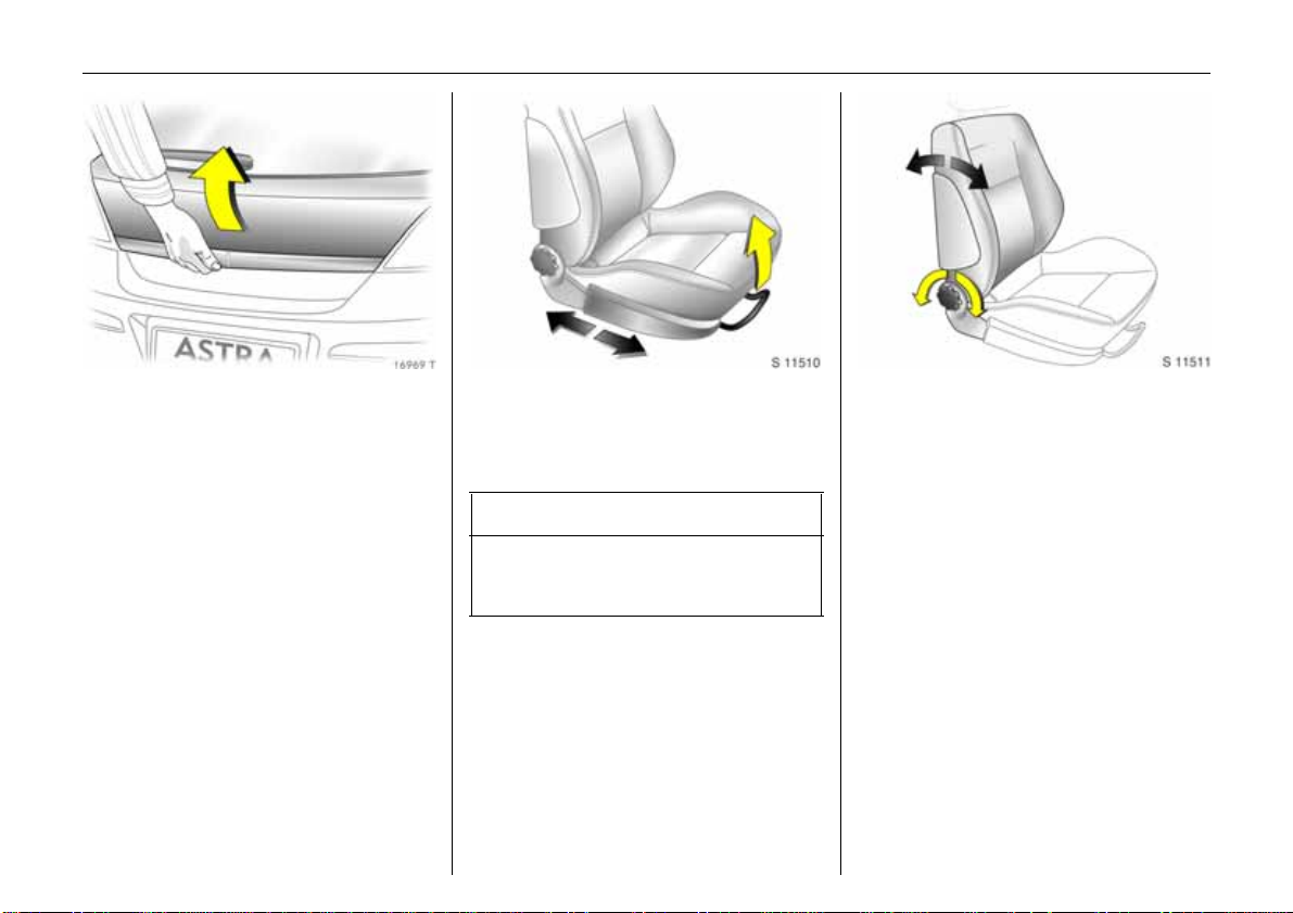
To adjust front seat height 3:
Ope rate lever on outboar d side of
sea t
Pump a ction on lev er
up: seat hi gher
down: seat lower
6 Seat – page 64, seat position – page 67.
Pict ure no: 16974t. tif
To adj ust f r ont se at inclinat io n3:
Pull inner lever on front of se at,
adjust inclination, release lever,
engage seat in position
A djust the inclination by dis tributin g body
weight.
6 Seat – page64, seat position – page 67.
Pic tur e no: 16975t.t if
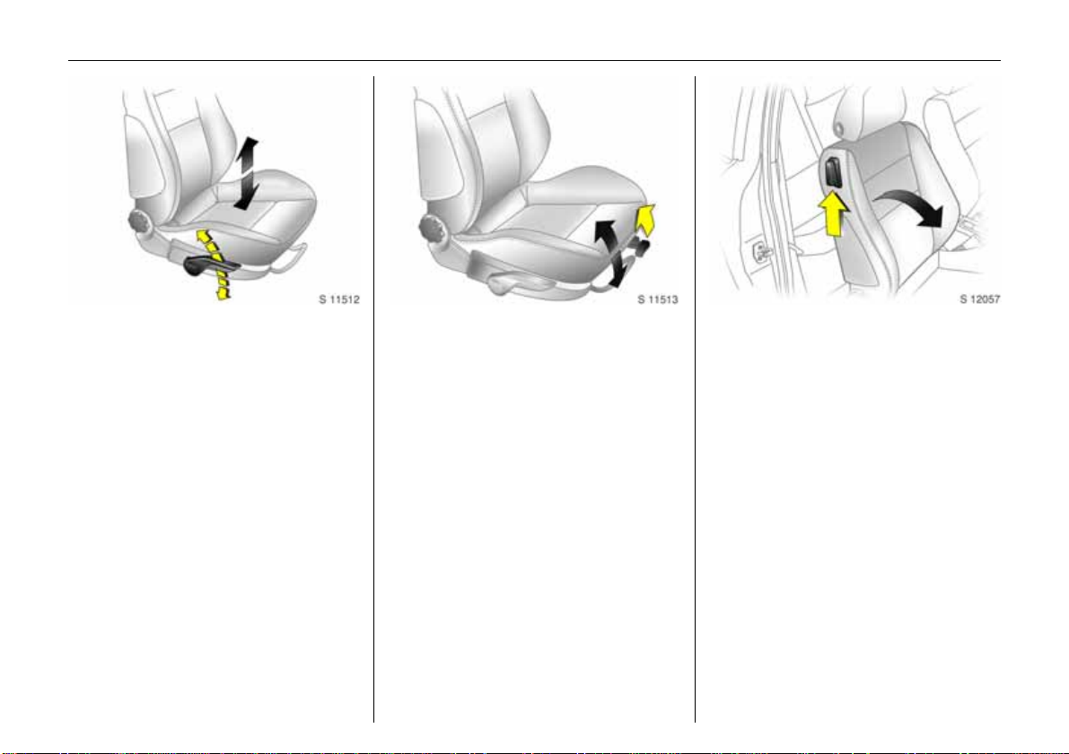
Tip the front seat backs
forward 3:
Lift release lever,
tilt seat back forward,
lowerrelease lever,
s eat b ac k is enga ge d in tilted
position3,
slid e sea t forwards3
To st raig h ten the seat, slid e back and it
engages in its original position 3. R aise
release lever 3, straighten seat back, lower
release lever, seat back engages.
The seat back can only be tipped forwards
from an upright position.
Panorami c wi ndscreen 3: before folding
the seat, push the head restraints down
and close th e sun visors.
6 Seat – pag e 6 4.
Page 9

5In Brief
Pict ure no : 16976t.t if
To adjust he ad restr aint hei ght of
front and rear outboard seats:
Press button to rele ase, adjust
height, engage in pos ition
6 Head restraints – see p age 68,
adjust re a r c entre head restraint – see
page 68,
head restraint position – see page69,
head restraint removal – see page 69.
Pict ure no: 16981t. tif
To fit seat belt:
Draw seat belt smoothly from
inertia reel, guide over sho uld er
and engage in buckle
T he seat belt must not be twis ted at any
point. The lap belt must lie snugly against
the body. The fron t seat backrests must not
be tilted back too far (recommended max.
tilting angle approx. 25°).
T o release belt, press red button on belt
buckle.
6 T hree-po int seat belts – see page 85,
Vauxhall Full Size airbag system –
see page 92,
seat position – see page 67.
Page 10
6In Brief
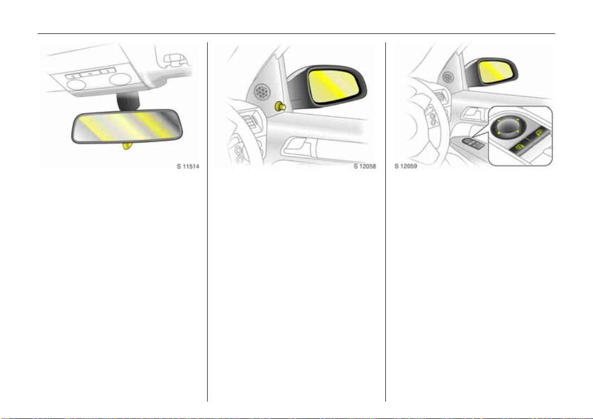
Pict ure no : 16977t.t if
Adjus t ing interi or mirro r:
Swivel mirror h ousing
Swivel lever on undersid e of mirror housing
to reduce daz zle a t night.
6 Mir rors – page 48,
automatic anti-dazzle interi or mirror –
page 49.
Pict ure no: 16978t. tif
To adjust exterior mirro rs
manually:
From inside, s wivel lever in
requ ire d dire c tion
6 Mirrors – see page 48,
aspherical exterior mirror – see page 48,
folding exterior mirror – page 48,
h eated exterior mirror – p age 157 .
Pict ure no: 18437T. t if
Electrical exterior mirrors 3
adjust:
Four-way switch in driver’s door
Press mirror switch right or left: Four-way
switch adjusts corre sponding mirror.
6 Mirrors – s ee page 48,
asph erical exterior mirror – see page 4 8,
folding exterior mirror – page 48,
heated exterior mirror – page 157.
Page 11
7In Brief
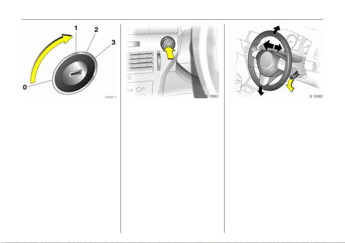
Pict ure no : 16982t.t if
St eering wheel lock and ignit ion:
Turn key to position 1. Move
steering wheel somewhat to
r elea se loc k
Positions:
0=Ignitionoff
1 = Steering released, ignition off
2=Ignitionon
for di esel engines: prehea ting
3=Starting
6 Starting – page 17,
electronic immobiliser – page 29,
parking the ve hicle – page 18.
Pict ure no: 17033t. tif
Steering wheel lo ck and ignition
on vehicl es with Open& S t ar t
system 3:
Mak e sure ele c tro nic k ey is in t he
interior reception ra nge and
press the Sta rt/Stop button.
Disengage the steering wheel
l o ck b y mo v in g t he st eering wh eel
slightly
T o start the vehicle, also operate brake or
clu tch pedal.
T o lock the steering wheel, switch ignition
off by pressing the Start/Stop button, open
driver’s door and engage steering wh eel.
Do not allow ve hicle to move whilst doin g
this.
6 Starting – page 17,
electronic immobiliser – page 29,
parking the vehicle – page18.
Pic tur e no: 17328t.t if
Steering wheel adjustment:
Move lever down, adjust height
and distance, move lever up,
engage
Adj ust steering wheel only when vehicle is
station ary and steering column lo ck is
released.
6 Vauxhall Full Size airbag system –
page 92.
Page 12
8In Brief
Page 13

9In Brief
Page
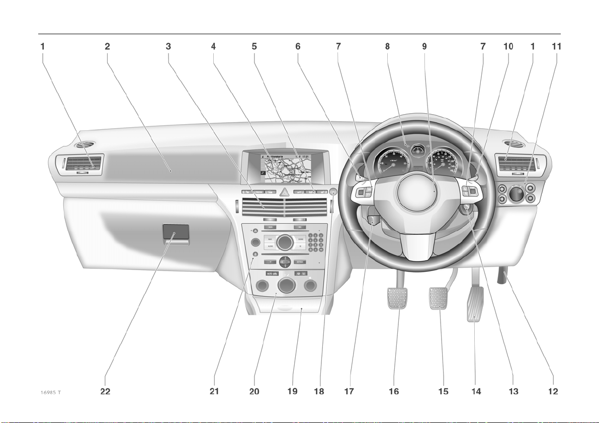
1 Side air vents .................................. 156
2 Fr ont passenger airbag .................. 93
3 Centre air vents ............................. 156
4 Central information display for
time, date, outside temperature,
infotainment system 3,
check contro l 3 ............. ........ ......... 138
Trip computer 3 ... .... ..... ........ .1 2 8, 134
Climate control system 3 .......... ... 168
5 Heat ed se at (left) 3 ...................... 157
Deflation
detection system 3 .. ..... .... ......... .... 21 7
Tyre pressure
monitoring sy stem3 ...................... 218
Parking distance sensor 3 ............ 214
Hazard warning lights .....................12
Central locking system ....................40
SPORT mode 3 ............................... 210
Heated seat (right) 3 ................... 157
Pa ge
6 T urn signal light, headlight flash,
dipped beam, high beam ............... 11
Switch off delay on 3 ..................... 148
Pa rking lights 3 ............................. 148
Cruise cont rol 3 ....... ........ ......... ..... 212
7 Remote control
on st eer i n g wh e e l 3 . ...................... 151
8 Instruments ..................................... 112
9 Horn ................. ......... ........ ......... ....... 12
Driver’s Airbag ................................ 93
10 Windscreen wiper,
winds creen wash system,
headlight wash system 3 and
rear window w ash
sy ste m ..... .... ..... ......... .... .... .. 12 , 1 3 , 1 4 1
11 Pa rk ing l igh ts, di pped b eam ........ 1 4 3
Instrument illumination .. ............... 148
Fog tail light ................................... 145
Fog lights 3 .................................... 145
Headlight range adjustment 3 .... 146
12 Bonn e t rele a se lev er . ........ ..... .... .... 2 4 1
Page
13 Start e r switch
with immobiliser ................................. 7
and
sensor panel for emergency operation
Open&Start sy stem 3 . ..... .... ..... .... .. 3 5
14 Accelerator pedal.................. 199, 199
15 Brake pedal ................... 199, 221, 221
16 Clutch pe dal 3............................... 199
17 Steering w heel adjustment ............... 7
18 S tart/stop button 3 ............. ..... 17, 32
19 Ashtray 3 ................ ......... ......... ..... 108
C igarette lighter 3 .. .... ..... .... ..... .... 107
20 Cli mate control ............................. 154
21 Infotainm ent system 3 ................. 151
22 Glove compartment ....... 34, 110, 156
Page 14

10 In Brief
Control indicators
0
I
R
v
v
X
Q
p
W
O p en& S t ar t sy s tem , f au l t ,
see pages 32, 112.
Engine oil pressure,
see page 113.
Brake sy stem , clu t ch syste m,
see pages 114, 221, 302.
Airb ag s yst em s, belt te nsioners,
deployable anti-roll bars 3,
see pages 87, 98, 104.
Electronic St ability P rogramme
Plus
(ESP®
see page 208.
Sea t bel t 3,
see pages 88, 114.
Door open,
see page 115.
Alternator,
see page 115.
Coolant temperature,
see pages 115, 300.
) 3,
A
j
IDS+
S
8
r
O
Y
>
C
r
Engine electronics,
gearbox electronics3,
immob iliser,
Diesel fuel filter 3,
fault,
see pages 29, 11 5,182, 1 88,
196, 206.
Easytronic 3, start engin e 3
see pages 115, 177.
Cont inuous Damping Contr ol 3,
SPORT mo d e 3,
see pages 210, 211.
Engin e oil level 3,
see pages 116, 298.
Exterior lights,
see pages 116, 143.
Parking distan ce senso r 3,
see page 214.
Turn signa l lig hts,
see pages 11, 11 6.
Fue l level,
see pages 116, 1 19,202.
Fog lights 3,
see pages 117, 145.
Main beam,
see pages 11, 11 7.
Fog tail light,
see pages 117, 145.
T
1
y
Z
u
!
w
B
m
Winter programme of
automatic transmission 3 or
Easytronic 3,
see pages 180, 186, 193.
SPORT mode of auto matic
tr ansm issi on 3 or Easytronic 3,
see pages 179, 185, 192.
Seat o ccupancy recognition 3,
see page 99.
Exhaust emission3,
see pages 117, 205.
An ti -lock Brake System,
see page 223.
Preheating system 3,
Dies el par ti cle filte r 3,
see page 118.
Deflation det ection syste m 3,
tyre pressure monitoring
system 3,
see pages 118, 217, 219.
Ad aptiv e for ward lightin g 3,
fault
see pages 147, 150.
Cruise control3,
see page 212.
Page 15
11In Brief
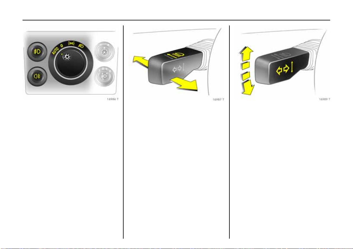
Pict ure no : 16986t.t if
Light switch:
7 =Off
8 = Parking lights
9 = Dippe d beam or m ai n
beam
A UT O = A u to m atic dippe d
beam ac tiv at io n3
Press button:
> =Fog lights3
r = Fog tail light
6 Lighting – page 143,
headligh t control indicator – page 140.
Pict ure no: 16987t. tif
Headlight flash, main beam and
dipped beam :
Headlight
flash
= Pull stalk
towards
steering wheel
Main be am = Push stal k
D i ppe d be am = Pu s h s t alk
fo r w ar ds again
or pull toward
steering wheel
6 Main beam, headlight flash – page 144.
Pic tur e no: 16989t.t if
Sw i tc h on turn s ig nal li ght s :
Right = Move stalk up
Left = Move stalk down
6 Turn signal lights – page 144.
Page 16
12 In Brief
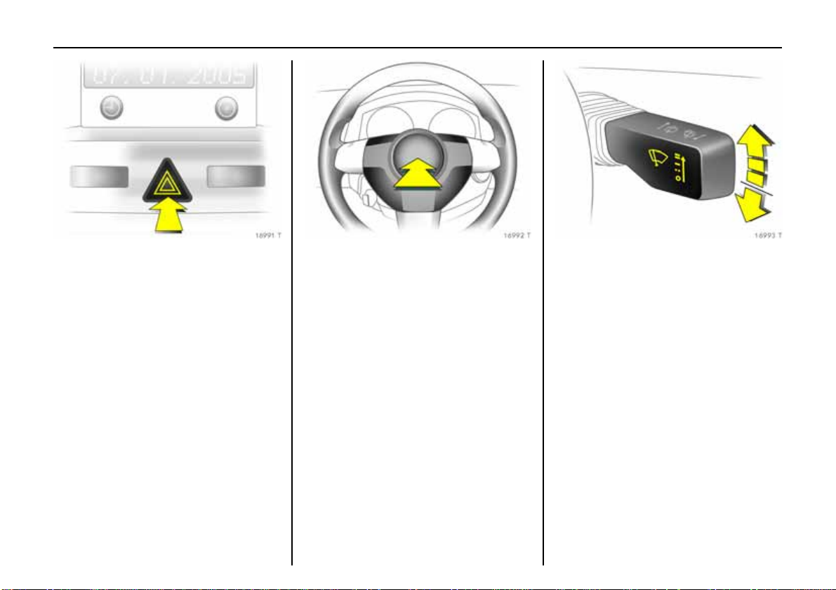
Pict ure no : 16991t.t if
Hazard warning lig hts:
on = pres s ¨
off = p ress ¨ ag ai n
6 Hazard warning lights – page 145.
Pict ure no: 16992t. tif
Activate horn:
Press j in centre of stee ring
wheel
6 Vauxhall Full Size airbag system –
page 93,
remote control on steerin g wheel3 –
page 151.
Pic tur e no: 16993t.t if
Win dscreen wiper:
Move stalk upward
§ =off
$ =timed interval wipe
% =slow
& =fast
Move stalk down from position§: Si ngl e
swipe.
6 Windscreen wiper – page141,
adjus table tim ed inte rval wipe 3 –
page 141,
further notes – page s 291, 303.
Page 17
13In Brief
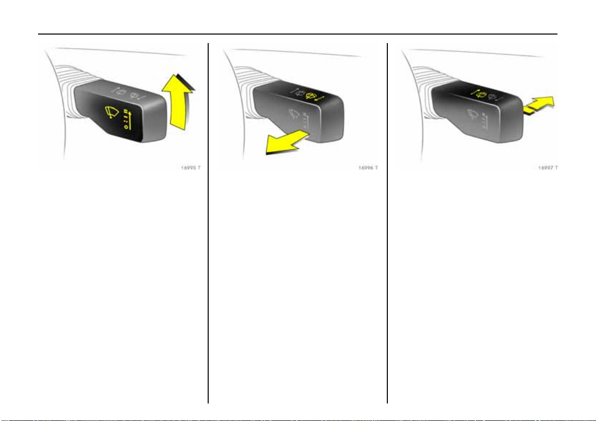
Pict ure no : 16995t.t if
Automatic wipi ng with rai n
sensor 3:
Move stalk upward
$ = a utomatic w iping with
rain sensor
§ =off
6 Windscreen wiper – page 1 41,
furt her notes – pages 291, 303.
Pict ure no: 16996t. tif
Ope r at i n g w ind sc ree n and
hea dlight wash sy stems 3:
Pull stalk to wards steering whee l
6 W indscreen and headlight w ash systems
– page 142,
further notes – pages 2 91, 303
Pic tur e no: 16997t.t if
Activate rear screen wiper 3 and
wash system 3:
Wiper on = Sta lk forwards
Wiper on = Sta lk forwards
again
Wash = H ol d sta l k fully
forwards
6 Rear s creen wiper and wash system –
page 142,
further notes – page s 291, 303.
Page 18
14 In Brief
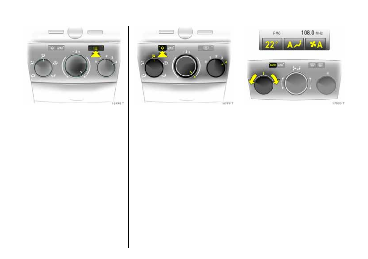
Pict ure no : 16998t.t if
Heated rear window,
heat ed exterior mirrors:
on = p ress Ü
off = p ress Ü ag ai n
6 A ir conditioning – page154,
heated rear window – page 157.
Pict ure no: 16999t. tif
To de mist or defros t windows:
Set ai r dis tribution to l,
rot a ry sw itc h fo r t em p erature
and air fl ow clockwi se;
Air conditi oning system 3:
al so pre s s b ut t o ns n;
Automatic air conditioning
system 3:
pre ss bu t to n s n and v,
turn rota ry switch for
tempera t ure c lo c kwi se,
air flow to A;
Climate c ontr ol s ystem 3 :
press button V
6 Climate control system 3 – page 154.
Pic tur e no: 17000t.t if
Set automatic mode on climate
con t rol syst em 3:
Press AUTO,
pr e-select te mpera t ure wit h
rotar y knob,
open ai r vents
6 Climate control system 3 – page 168.
Page 19
15In Brief
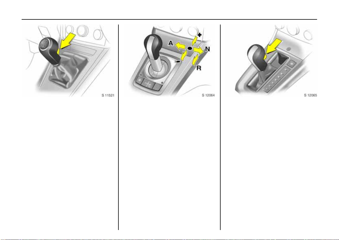
Pict ure no : 17001t.t if
Man ual transmissio n:
Reverse: with the vehicle stationary, wait
3 seconds after de-clutching and t hen pull
up the button on the selector lever and
engage the gear.
If the gear doe s not engage, set the lever in
ne utral, release the clutc h pedal and
depress again; then repeat gear selectio n.
Pict ure no: 17002t. tif
Easytronic 3:
N=Idle
o =Drive position
+ = Higher gear
- = Lo w e r gear
A/M = Change between
Autom a tic and Manual
mo de
R = Rev e rs e ge ar (w ith
selector lever lock)
T he selector lever must always be moved in
the appropriate direction as far as it will
go. Upon release, it automatically returns
to th e centre positi on. Pay heed to the
gear/mode ind icator in the transmission
display.
The foot brake must be depressed when
starting.
6 Easytronic 3 – page176.
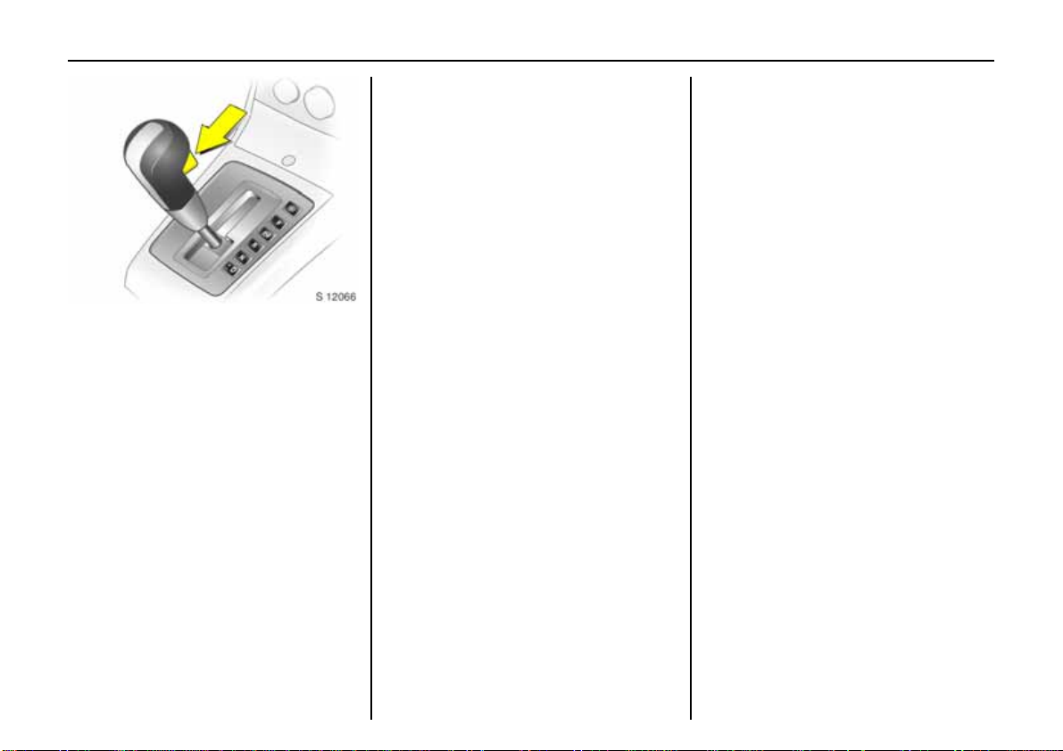
Pic tur e no: 17003t.t if
Autom atic transmission 3:
P=Park position
R=Reverse gear
N=Neutral (idle)
D = A utomatic gear sele ction
3 = 1 st to 3r d ge ar
2 = 1 st and 2nd ge ar
1=1st gear
Starting only possible in P or N. To move
from P, switch on i gnition, depress foot
brake and press button on selector lev er.
Press button on selector lever to engage P
or R.
P only when vehicle is stationary, first
apply handbrake
R onl y when vehicle is stationary
6 Automatic tra nsmission 3 – page 18 4.
Page 20
16 In Brief
Pict ure no : 17330t.t if
Autom atic trans mission
with ActiveSelect 3:
P=Park position
R = Re vers e gear
N=Neutral (idle)
D = Auto m ati c ge ar sel ect ion
Selec t or lever in D to lef t:
Manual mode
+ = Higher gear
-=Lower gear
P or N must be engaged when starting.
To move from P or N, switch on ignition,
depress foot b r ake and press button on
selector lever.
To se l ec t P or R, pres s b utton on sele ctor
lever.
P only with vehicle stopped, first apply
handbrake
R only when vehicle is stationary
6 Automatic transmission 3 – see
page 184.
Befor e starting off, check:
z Tyre pressure and tyre condition –
pages 225, 337.
z Engine oil level and fluid levels in engine
compartment – see pages 2 98 to 305.
z All windows, mirrors , exterior lig hting
and number plates are free from dirt,
snow and ice and operational.
z Do not place any objects in front of the
rear window, on the in strument panel or
in the area in which the airbags inflate.
z Seats , seat belts and mirro rs are
correctly adjusted.
z Check brakes.
Page 21
17In Brief
Press button again to repeat the starting
procedure or switch o ff the engine.
To turn on the ignition, do not press the
brake or clu tch pedal; just press the button
brie fly.
Do not start unless vehicle is stationary.
6 Open&Start-System 3 – page 32,
Electronic immobiliser – page 29,
Diesel fuel system – page 242.
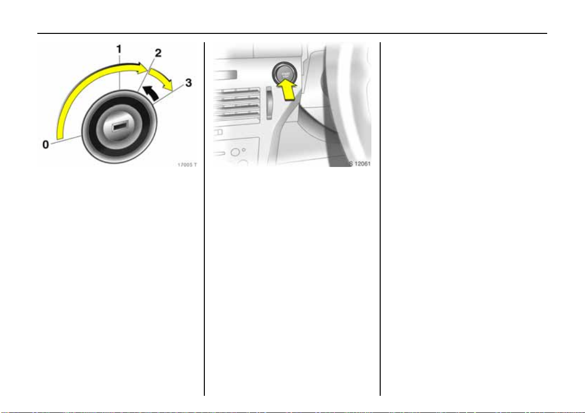
Pict ure no : 17005t.t if
To start engine:
O per at e c lutc h a nd brake,
autom atic trans mission 3 in P
or N,
Easytronic 3: Depress brake,
do not acce lerate,
Petrol e ngine: Turn keyto 3;
Diesel engin e: Tur n key to 2, when
contro l ind icator ! goes o ut
1)
turn key to 3; release key once
engine is running
Before restarting or switc hing off the
engine, turn key back to 0.
To switch on the ignition, only turn the key
to 2.
6 Ele ctronic immobiliser – page 29,
Diesel fuel system – page 242.
Pict ure no: 17033t. tif
To start engine with Open&Star t
system 3:
The electronic key must be inside
reception area inside the car,
operate clutc h or brake,
Automatic transmission 3 in P
or N, Eas ytronic 3: D e press brake,
do not accelerate,
Petrol e ng ine: Press bu tton;
Diesel engine: Briefly press
button; when control indicator !
goes out1) pre ss bu t to n agai n for
1 second; release button once
eng ine is running
1)
Preheating system switches on only if ou tside
tempera ture is low.
Page 22
18 In Brief
To activate the mech anical anti-thef t
locking system 3 and the Vauxhall alarm
system 3 press button p tw ic e or with
Open&Start sy stem 3 touc h sensor in one
of the front d oor handles twi ce.
6 Further i nformation – see pages 29, 198,
Open&St art system – page32,
radio remote control – s ee page 30,
central locking sys tem – see page 38,
Vauxhall alarm system3 – see page 44,
TwinTop r oof ope r ation3 – page 56.
Vehicle decom missioning – s ee page 307.
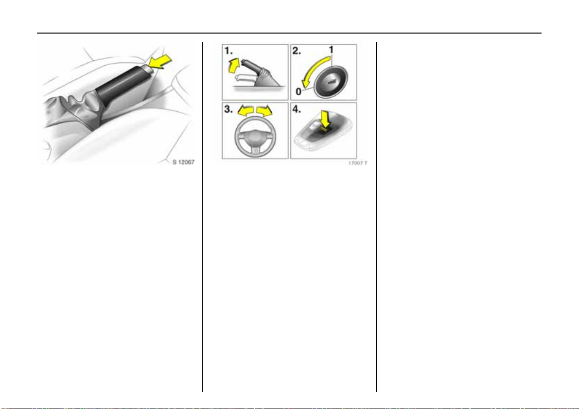
Pict ure no : 17006t.t if
Releasing the hand brake:
Rai se lever slig h tly,
press lock button,
l o wer lever fu lly
6 Handbrake – page222.
Pict ure no: 17007t. tif
Parking the vehicle:
Apply hand br ake firmly,
engineoff, ignition off,
l o ck s t eering wheel,
lo ck v eh icle
To lo c k, press button p of ra d i o r em o t e
con trol for Open&Start system 3 touch
sensor in a door handle on the front doors.
With Open&Start system 3, the driver’s
door must be opened to lock the steering
wheel.
Page 23

19In Brief
Advice when parking:
z Do no t p ar k the v eh icl e o n an eas y
flammable s urface. The high
t em per at ur e o f t he ex ha us t s ys tem c ou ld
ignite the surface.
z Always apply th e hand brake firmly.
A pply the hand brake as firmly as
possible on uphill or downhill slopes .
To reduce operat ing forces, depress foot
brake at the same time.
z Close the windo ws and sun roof3 or
Tw inTop.
z For m anual transmission, select f irs t or
reverse; for automatic transmission 3
move selector le ver to P, fo r Ea sy t ro n ic3
sele c t first or reverse before switching off
the ignition (note gear display, see
pages 177, 184, 191).
z On v eh i c l e s wi th a uto m a ti c
transmission 3 the key can only be
withdrawn when the selector lev er is in
pos ition P. For the Open&Start Sys tem 3,
"P" flashes in the gear display for a few
secondsif P is not engaged or the
handbra ke is not applied.
z On vehicles with Easytronic3 control
indicator R flashes for a few seconds
after the ignition is switched off if the
hand bra ke has not been app lied– see
page 182.
z With the Open&Start system 3 the
en gi ne can onl y be swit che d of f whe n the
car is stationary.
z Turn steering wheel until the steering
loc k perceptibly enga ges (Anti-theft
protection) after first withdrawing the
ignition key; for Open&Sta rt-System 3
switc h off ignition and open driv er’s
door.
z The engine cooling fans may run after
the engine has been switched off – see
page 297.
6 F urther informatio n – pages 30 6, 307 .
That was the most i mportant
information in brief for y our first
dr ive in your vehi c le.
Th e ot h e r p age s of th i s ch ap t e r
contain a summar y of the
noteworthy functions of your
vehicle.
The remaining ch apters of the
Owne r’s Manual contain
imp or tant in fo rmation on
ope ration, safety and
ma intenance as well as a
com plete index.
Page 24
20 In Brief
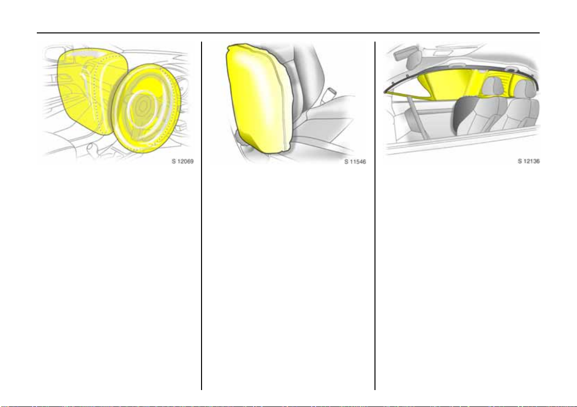
Pict ure no : 17009t.t if
Vaux hall Full Si ze ai rbag system
The Vauxhall Full Size airbag system
co n si s t s o f se ver a l se p ar a te sy st e m s.
Front airbag system
The front airbag system will be triggered in
the event of a serious accident involving a
frontal impact and f orms safety cushions
for the driver and front passenger. The
forward movement of the driver and front
passenger is checked and the risk of
injuries to the uppe r body a nd head
thereby substantially reduced.
Side airbag system 3
Pict ure no: 17110t. tif
T he side airbag is triggered in the even t of
a side-on collision to form a safety cushio n
for the driver or front passenger in the
respective door area. This substantially
reduces the risk of i njury to the upper body
and pelvis.
Curtain airbag syst em 3
Pic tur e no: 17351t.t if
The curtain airbag system triggers in case
of a side-on collision and provides a safety
barrier in the head area on the respec tive
si de of the vehicle. Thi s reduces the ri s k of
injury to the head considerably in case of a
side-on collision.
6 Vauxhall Full Size airbag system –
page 92.
Page 25
21In Brief
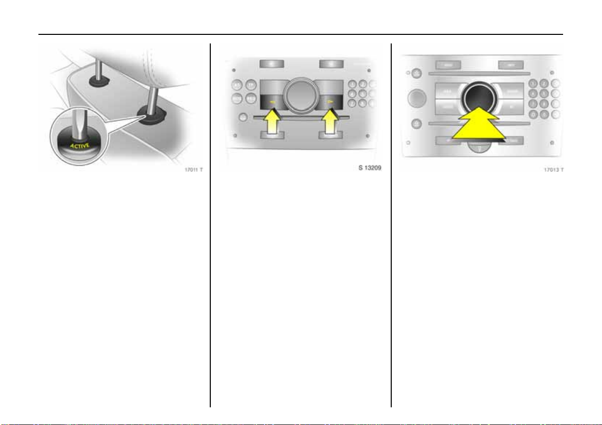
Pict ure no : 17011t.t if
Acti ve head restraints3 on front
sea ts
In the event of a rear-end impact, the
active head restraints tilt forward a little.
The head is more effectively supported by
the head res tra i nt and the danger of
injuries caused by whiplash in the neck
area is reduced.
Active head re straints are i dentified by the
lettering ACTIVE on th e head restraint
guide sleeves.
6 Headrests – page 68.
Picture no: S0013209. t if
Operating menus in the
information display 3
Menu opt ions are selec te d using menus
and using the arrow keys the multi-f unction
but ton of the Infot ainmen t syst em 3 or the
left-hand adjuster wheel 3 on the stee r ing
wheel. The respective menu options are
shown on the display.
Select with the a rrow keys 3: press right or
left key.
S elec tion us ing multi-function button 3:
Pic tur e no: 17013t.t if
rotate and press multi-function button.
To exit a menu, turn the multi-fun ction
button l eft or rightto Re turn or Main and
select.
Selection with left adjuster wheel on
s tee r ing wh ee l 3: turn adjuster wheel and
pre ss.
6 Inf ormation Display – page 122.
Page 26
22 In Brief
Ü Board Computer 19,5° 19:36
BC 1 All values
BC 2
Timer
Tyres
1
257.0 miles
Ø40mph
7.0 ga l
8
Ø 31.0 mpg
Coolant level
check
OK
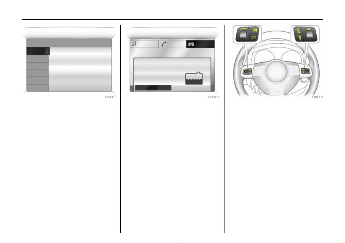
Pict ure no : 17344t.t if
Trip computer 3
The trip computers provide information on
driving data, which is continually recorded
and evaluated electronically.
Functions:
z Range
z Instantaneous cons umption
z Distance tra velled
z Average speed
z Effective consumption
z A verage consumption
z Stop watch
z Tyre pres sure 3
6 Tr i p com p u t er 3 – pa ges 1 28,13 4.
Pict ure no: 17339t. tif
Check co ntrol 3
The che c k control software monitors
z Fluid levels
z Tyre pressure 3
z Radio remote con trol ba ttery
z Vauxhall alarm system 3
z Important exterior lights, including
cables and fuse s.
6 Check-Control 3 – page 138.
Pic tur e no: 17015t.t if
Remote control on steering
wheel3
The functions of the infotain ment system 3
and the information display can be
operated with the remote contro l on the
s tee r ing wh ee l .
Further information is available in the
infotainment system operating
ins truction s.
6 Remote control on steering wheel 3 –
page 151, Infotainment System –
page 151.
Page 27
23In Brief
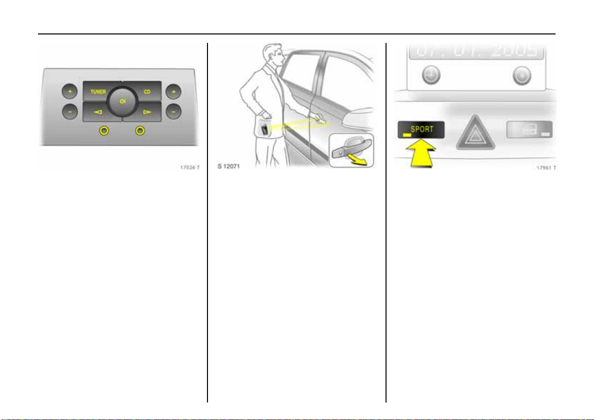
Pict ure no : 17026t.t if
Twin Audio 3
Twin Audio allows rear seat occupants the
choice between the audio source played on
the infotainment system or a separate
audio source.
Only an audio source that is not currently
active on the infotainment system can be
contr olled using Tw in Audio.
Two headphone connections are availabl e,
with separate volume controls.
Further information is available in the
infotainment system operating
instructions.
6 Tw in Au d i o 3 – page 152.
Pict ure no: 17333t. tif
Op en & Start sy st em w it h
e lectronic key and radio remove
contro l 3
The Open&Start syst em al lows the vehicle
to be lock ed and u nlocked, including
mechanical anti-theft locking system 3
and the Vau xhall alarm system 3 without a
mechanical key and the engine to be
started and stopped using a start/stop
button. All the driver has to do is carry the
e lectronic ke y around with him.
6 Open&Start System 3 – page 32.
Pic tur e no: 17961t.t if
Sport mode 3
To activate
Press button SPORT.
SPORT mode is used to change
damping 3, ste erin g 3, thr ottle
applicati on and the shift point for
Easytronic 3 and automatic
transmission3 while driving.
Damping and steering become more dire ct
and p rovide b etter contact with the road
surface. The engine reacts more quickly to
accelerator movements.
With Easytronic 3 and automatic
transmission3, the shift times are
shortened an d shifting takes place at
high er re vs (not with cruise control
ena bled 3).
6 Sport mode 3 – page 210.
Page 28
24 In Brief
Ü Board Computer
BC 1
BC 2
Timer
Tyres
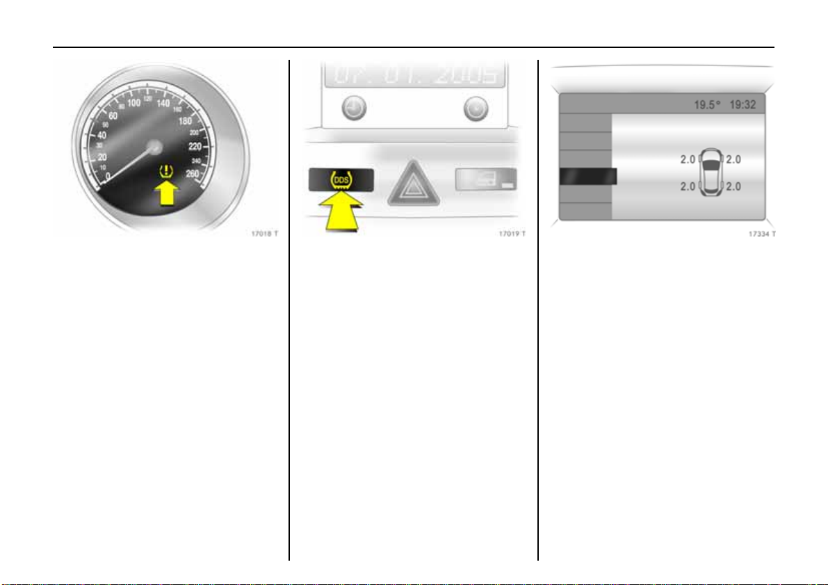
Pict ure no : 17018t.t if
Deflatio n De t ec tio n Sys tem
(DDS) 3
The d eflation detectio n sy stem
continuousl y monitors the speed of al l
wheels while driving. If a tyre loses
pr essure, it grows sma ller and th erefore
rotates more quickly than the other wheels.
If the syst em detects a di fferen ce in speed ,
the control indicator w illuminates in red.
After tyre pre ssure is corrected or a tyre or
Pict ure no: 17019t. tif
wheel is changed, t he system must be
in itialised by pressing the DDS button.
6 Tyre deflation detection system 3 –
page 217.
Pic tur e no: 17334t.t if
Tyre pres sure monitoring
system 3
The tyre p ressure monitoring system
continually checks the pressure and speed
of all four wheels while driving.
A pressure sensor is installed in each wheel.
The inflation pressures of the individual
wheel s are transmitte d to a controlle r,
where they are compared.
The curre nt tyre pressures can be
displayed on the graphical information
display or the colour information display 3.
Deviating tyre pressures are displayed in
the form of mess ages on the info rmation
display whilst driving.
6 Tyre pressure monitorin g s ystem 3 –
page 217.
Page 29
25In Brief
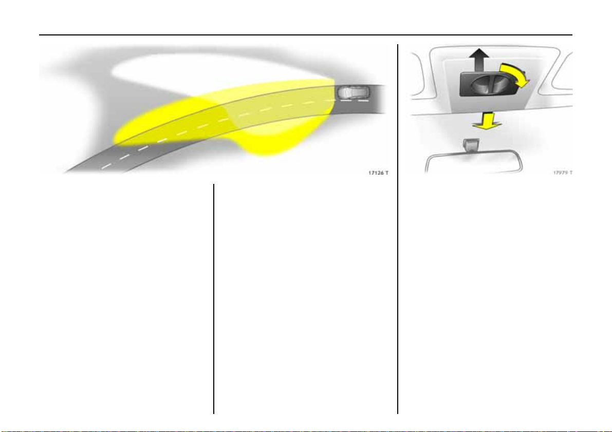
Pict ure no : 17126t.t if
Adaptive Forward Lighting
(AFL) 3
improves lighting in curves (curve lighting)
on vehicles with Bi-Xenon h eadlight
system.
Curve lighting
Picture no:
The Xenon light beam pi vots based on
steer ing wheel position and speed (f ro m
approx. 6 mph / 10 km/h).
Motorway lighting
At higher speeds and continuous straight
ahead trav el, the dipped beam
automatically raises slightly, thereby
increasing headlight range.
6 Adaptive driving lights 3 – page 147.
Pic tur e no: 17979t.t if
Panoramic windscreen 3
To open:
Turn the handle to the right and move the
roof lin ing rear ward to a suitable pos itio n.
To close:
Move the roof lining forward to a suitable
position. When moved all the way forward,
the roof lining engages in position.
6 Pan orami c roof 3 – page 53.
Page 30
26 In Brief
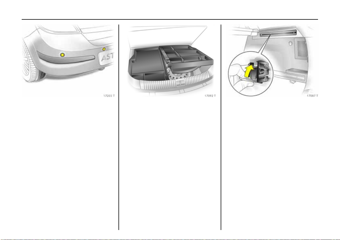
Pict ure no : 17203t.t if
Parking di st an ce sens or3
When reverse gear is selected, the Parking
distance sensor s witches itself on
automatically.
T he parking distance sens or can also be
activated at speeds of less than 15 mph (25
km/h) by pressing the r button on the
instrume nt panel.
If the vehicle approaches an obstacle when
reversing, a series of signals can be heard
in the vehicle interior. The interval between
the signals becomes shorter as the
distance is reduced. If the distance is less
than 30 cm, the signal will be continuous.
6 Park ing dist ance s ensor 3 – page 214.
Pict ure no: 17092t. tif
Ca rgo b o x 3
Collapsible box to divide the luggage
compartment.
The cargo box may o nly be loa ded when
the backrests are engaged in an upright
position.
When removing, start with the right half.
6 Car go B ox3 – pag e81 .
Pic tur e no: 17087t.t if
FlexOrganizer 3
The side walls contain retaining strips,
where various components ca n b e
attached to divide the luggage
compartment or fasten loads.
T h e sy st e m co n si s t s o f
z Adapters
z Variable partition net
z Mesh poc kets for the sid e walls
z Hoo ks in the luggage co mpartme nt
6 FlexOrganizer 3 – page80 .
Page 31

27In Brief
The roof is oper at ed with the buttons on
the ro of console above t he mir ror or with
the remote contro l.
To improve luggage compartment
accessibility, the electric loading aid makes
it poss ible to raise the open roof when it is
sto wed in the luggage compartmen t.
6 TwinTop – see page 56.
Pict ure no : 17980t.t if
Lu ggage compart m e n t c ove r ,
Estate
To open:
Press h andle on luggage compartment
cover down. The cover automatically
unrolls.
6 Luggage compartment cover 3 –
page 76.
Pict ure no: 17981t. tif
Astra Twi nTop
With TwinTop, a co nvertible h ardtop, Astra
u nites the benefits of a cou pe with those of
a convertible.
To opti mise safety, the Astra TwinTop is
equipped with a rollover protection system
with reinforced windscreen frame and the
choice of fixed or deployab le anti-roll b ars
in addition to the front and side airbag
systems.
Page 32

28 Keys, Doors , Windows, Tw inTop
Keys, Doors, W indows,
TwinTop
Replacement keys ............................... 28
Ca r Pass ... .... .... ..... ......... .... ..... .... .... ...... 2 8
Key with fo ldaw ay ke y sect ion 3....... 28
Electronic immobiliser.......................... 29
Store perso na l vehicle settings in the
vehicle key 3 ..................................... 30
Radio remote control with 3
mec han ica l key . .... ..... .... ......... .... ..... . 30
Open&Start sy stem 3.......................... 32
Central locking system ........................ 38
Fault when locking or unlocking......... 42
Lug gage compartment ....................... 43
Vauxhall alarm system 3.................... 44
Child safety locks 3............................. 47
Exterior mirrors..................................... 48
Interior mirror....................................... 49
Electric windows 3 ............................... 50
Panorami c wi ndscreen 3.................... 53
Sun r o o f3 ............................................ 54
TwinTop................................................ 56
Replacement keys
The key numb er is spec ified in the vehicle
documents and in the Car Pass 3.
The key is a constituent of the elec tronic
immobiliser. Ordering keys from a Vauxhall
A uthorised Repairer guarantees problemfree operation of the electronic
immobiliser.
When el ectronic ke ys of the Open&Start
system are being replaced, all keys must be
handed to the d ealer for programming.
Keep the spare k ey in a safe spot.
Locks, see p age291, Open&Star t system,
electronic k eys, see page 32.
Car Pass
The Car Pass contains all of the vehicle’s
data and should therefore not be kept in
th e vehicle.
Have your Car Pass on hand w hen
consulting a Vauxhall Authoris ed Repairer.
Pic tur e no: 17027t.t if
Key with foldaway key section3
Press button to extend. Press button to
retract; key section engages audibly.
Page 33

29Keys, Doors, Windows , TwinTop
Pict ure no : 17349t.t if
Electronic immo biliser
The s yst em c hec ks whet h er t he vehi cl e ma y
be started with the mechanical key or
electr onic k ey of the Open&Start syst em3
that is being used. If the key is recognised
as " authorised" the vehi cle can be sta rted.
The check takes place via a transponder in
the key.
The electronic immobiliser activates itself
automatically after the key has been
removed fro m the ignition or, with the
Open&Start sy stem 3, when the engine is
switched off by pr essing the Start/S top
button.
The c ode number of the electronic
immobiliser is given in the Car Pass .
Control indicator for immobiliser A
Pict ure no: 17033t. tif
Con trol ind ica tor A illuminates briefly
when the ignition is switched on.
If the control indicator flashes when the
ign ition is on, there is a fault in the s ystem;
the engi ne c annot be st arted . Switch off
th e ignition an d then repeat the s ta rt
attempt.
If the control indicator A cont inues to
flash, try to s ta rt the engine using the
second key and contact a workshop f or
assistance.
If control indicator A il l u m i na te s a ft e r th e
Pic tur e no: 17028t.t if
engine i s starte d, th ere i s a fault in the
engine ele ctronics or transmission
electronics 3 (see pages 182,188, 196, 206)
or there is water in the diesel fuel filter 3 (s ee
page 300).
Note
The immobiliser does not lock the doors.
Therefore, after leaving the vehicle always
lock it and switch on th e Vaux hall alarm
system 3 – see pages 38 , 45.
Page 34

30 Keys, Doors , Windows, Tw inTop
Store pers onal vehic le settings in
the vehicl e key 3
The last setting s selected
z for the climate control system 3
z i nformation display 3
z Infot ain me nt syste m 3
z i nstrument illumination
are stored automatically depending on the
vehicle key used.
Differe n t settin gs stored for each vehicle
key are retrieved automatically on use of
the vehicle key concerned.
Each time the vehicle i s locked, the settings
are s aved again.
Pict ure no: 17029t. tif
Ra di o remote control with 3
mech ani c al ke y
Dependin g on vehicle equipment level, one
o f the remote controls shown on this page
will be used.
Radio rem ote control in vers ion with
Open&Start sy stem 3 see page 32.
T he radio remote control is integrated in
th e key.
Used to op erate:
z central locking syste m,
z mechanical anti-th eft locking system 3,
z Vauxhall alarm system 3.
Depend ing on the equip ment level of the
vehicle 3, the wind ow s of vehicl es with
electric windows in a ll doors 3 can be
opene d or closed from outsid e using th e
ra dio remote control. See pa ge 41 .
On the Astra TwinTop, the roof can also be
Pic tur e no: 17030t.t if
opened or closed with the remote
cont r ol 3.
The ra dio remote con trol has a rang e of
app rox . 5 metres. This ra ng e can be
aff ected by outsid e infl uences. Aim the
remote control at the vehicle to operate.
Handle the radio remote cont rol wi th care,
protect it from moisture and high
temperatures an d avoid unnecessary
operation.
The hazard warning lights come on to
indicate that the remote control is
ope r ational.
Page 35

31Keys, Doors, Windows , TwinTop
Central locking, mechan ical anti-theft
locking system 3,
see page 38.
Vauxhall alarm system 3,
see page 44.
Electric windows3,
see page 50.
Astra TwinTop,
see page 56.
Fault
If the centr al locking system cannot be
operated with the radio remote control, it
may be du e to the following:
z The ra nge o f the ra dio remote con trol
has been exceeded.
z Radio remote con trol ba ttery volt ag e is
too low. Battery replaceme nt - see right
hand column.
z F req u ent , r epe a ted op er at io n o f the
radio remote control outside the
reception range of the vehicle (e.g. too
far from v ehicle, remote control is then
no long er recognised). Remote cont rol
synchronisatio n - see rig ht hand column.
z If the central locking system is
ove rloa ded as a resu lt of repeated
operation at short intervals. The power
supply is cut off for a brie f period .
z Interference from higher-power radio
waves f rom other sources.
T o eliminate the cause of a fault, we
recommend c o ntac ting a wor kshop f or
assistance.
Open driver’s door with key, see page 42.
Remote control b attery replacement
Replace the battery as soon as the range
of the radio remote control begins to
shrink.
K ey wit h folda wa y key sect io n
Pic tur e no: 17031t.t if
Extend key, see page 28 . Open radio
remote control. Replace battery - battery
typ e, see pa ge 3 48 - n oting in stallation
position. Close radio remote control.
Make sure that you dispose of old b atteries
in accordance with environmental
protection regula t ions.
Key with fixed key section
Have the battery changed by a workshop.
Synchronise the radio remote contro l
after malfunctions or battery ch ange
After changing the battery, unlock the
door with the key in the lock. Turning on the
ignition will synchronise the radio remo te
cont rol.
Page 36

32 Keys, Doors , Windows, Tw inTop
Pict ure no : 17333t.t if
Open&Start sy stem 3
The Open&Start system allows the v ehicle
to be locked and unlocked, including the
mechanical anti-th eft locking system 3
and the Vauxhall alarm system 3, and the
engine to be started and stopped without
a mechanical k ey. All the driver has to do is
keep the key on his person.
Depending on the equipment lev el of the
vehicle 3, the windows of vehicl es with
electric windows in all doors 3 can be
opened or closed from outside using the
remote control of the elec tronic k ey. See
page 41.
On the Astra TwinTop, the roof can also be
opened or closed wi th the remote control3
of the electronic key.
The electronic k ey mus t be w ithin the
Pict ure no: 17032t. tif
external reception range about 1 metre
from the vehicle in order to lock and unlock
th e vehicle.
If the electronic key is recognized as
"authorised", t he ve hicle can be un locke d
by pulling a door handle or the knob
beneath the tailgate handle and the doors
and the tailgate can be opened.
When the Start/ Stop bu tton is press ed, the
Pic tur e no: 17033t.t if
system re -checks the authorisation. The
electronic key has to be recognised i n the
interior in orde r to do this. After the key has
been authorised the ign iti on switches on.
At the same time, the electronic
imm obiliser is s witched off a nd the electro-
mechanical steer ing column lock is
deactivated. Pressing the Start/ Stop button
again with the brake or clutch pedal
depressed or in P or N with automatic
transmission3 starts the engine. Press the
button for at le ast one second with the
vehicle sta tionary or hol d unti l the engi ne
starts.
Page 37

If the brake or clu tch pedal is depressed ,
the engine can be started right away with
a single press on the Start/Stop button.
Releasing the Start/Stop button interrupts
the starting procedure.
The engine and the ignition are switched
off by pressing the Start/Stop button again.
The v ehicle must be stationary. The
immobiliser is activated at the same time.
If the ignition has been switched off and
the vehicle is stationary, the steering wheel
lock activates automatically when the
drive r’s door is opened or close d.
The electronic key mu st be within the
interior reception in order to switch the
ignition on or off. We rec ommend that the
driver carries the electronic key on his or
her person. If the electronic key is not
recognised , try a different positio n for the
key.
Do not put the electronic key in the
luggage compartment or in front of the
informatio n display.
T he vehicle is locked fro m the outside with
Pict ure no: 17034t. tif
the doors closed b y touching the s ensor
panel in the door handle of one of the front
doors. The elec tronic key must be with in
th e external recep ti on range of
approximately one metre from the vehicle.
The Open&Start sy stem 3 does not the lock
th e vehicle automatically if the electronic
ke y is outside the external reception range
o f approximately one metre from the
vehicle.
33Keys, Doors, Windows , TwinTop
Pic tur e no: 17035t.t if
Radio remote control
The vehicle can be locked and unlocked by
conventional means using the radio
remote control with the buttons on the
electr onic key.
In addition, the mechanical anti-theft
locking syst em and Vauxhall alarm sys tem
can be armed and disabled using the radio
remote control. Depending on the
equipment level of the vehicle 3, the
windows of vehicles with electric windows
in all doors 3 can be opened or clos ed fr om
outside using the radio remote control.
6
Page 38

34 Keys, Doors , Windows, Tw inTop
The radio re m ote cont rol has a range of
approx. 5 met res. This range can be
aff ected by outsid e influences. Ai m the
remote control at the vehicle to operate.
Handle the radio remote con trol wi th care,
protect it from moisture and high
temperatures and avoid unnecessary
operation.
The hazard warning lights come on to
indicate that the remote control is
ope ra tional.
Central locking, mechan ical anti-theft
locking system 3,
see page 38.
Vauxhall alarm system 3,
see page 44.
Electric windows3,
see page 50.
Astra TwinTop,
see page 56.
Control indicator for Open&Start
Pict ure no: 17036t. tif
system 0
If the control indicator flashes 0 with the
ignition swit che d on or wit h t he engine
running an operating err o r has occurred,
e.g. the electronic key is no longer within
the reception rang e of the vehicle i nterior.
During the nex t starting pr ocedure the
engine m a y not b e able to be started. Press
Start/Stop key somewhat longer to switch
th e ignition o ff.
Flashing of the 0 can also be an indication
o f complete failure of the electronic key. In
this case operation is only pos sible us ing
the emergency facility – see page 35.
InSP3 in th e service display or an
appropriate message in the information 3
display indicates that the batte ry of the
electronic key needs replacing – see
page 36.
If the control indicator 0 is permanently
on, an error has occurred in the system.
Lock o r unlock vehicle usin g the ra dio
remote control or the emergency key if
necessary – see page42, or try using the
spare key.
If 0 illuminates, this can also mean that
the steering wheel lock is still locked: move
stee ring wheel to an d fro a little and press
Start/Stop button again.
If 0 illuminates while driving, there is a
system fa ult. Contact a workshop
immediately.
Emergency operation – see page 35.
Lockable glovebox, Astra TwinTop with
Open&Start system3
In addition to the electronic key of the
Open&Start sy stem, there is a standa rd key
without remote control for the glove
compartment lock.
Page 39

35Keys, Doors, Windows , TwinTop
Emergency operation
Pict ure no : 17037t.t if
If the Open&Start system fails or the
electronic key (control indicator 0 flashes
or permanently on) the driver’s door can be
lo ck ed o r un lo cke d wit h t he eme r genc y key
in the electronic key: press locking
mechanism on unders ide and remove cap
toward the front by applying gentle
pres sur e to the cap. Push emergency key
towards the outside over the detent and
remove.
Only th e driver’ s door can be locked and
Pict ure no: 17038t. tif
u nlocked using the emergency key. Unlock
the entire vehicle as described on page 42.
In t he version with Va uxhall a larm
system 3 the alarm may be trigge red wh en
the vehicle is unlocked. Switch ignition on
to deactivate alarm and release the
steering column lock: hold electronic key at
marked position on the steering column
panelling and press the Start/Stop button.
Repeat procedure if necess ary.
To start the engine, hold the ele c tronic key
Pic tur e no: 18439t.t if
at the m ark ed position, depress brake
pedal or clutch pedal or in vehicles with
automatic transmission 3 depress brake
pedal and engage P or N, Then pr ess the
Start/Stop button.
Pre ss sta rt/ st o p but ton for at l east 1 se c ond
to switch the engine off. Lock all doors
exce pt driver’s door as des cribed on
page 42. Unlock driver’s door with
emergency key.
This fa cility is for emergency use on ly .
Replace the b attery of the electronic key as
soon as possible or have the system
repaired. Contact a workshop for
assistance.
Page 40

36 Keys, Doors , Windows, Tw inTop
Radio remote control synchronisation
The radio remote control synchronises itself
automatically during every starting
procedure.
Replacing battery in electronic key
Pict ure no : 17040t.t if
Replace the battery immediately if the
system is no longer working properly or the
range of the radio remote control is
reducing. The need for a battery change is
indicated via InSP3 in the service di splay or,
in vehi cles with check control 3 , by an
appropriate message in th e display. See
page 120.
To replace the b attery, press the locking
Pict ure no: 17041t. tif
mechanism on the unders ide of the
electronic key and remove the cover
to wards the front by applying gentle
pressure - see page 35, figure 17037 T.
Push off cove r with embl em on the button
si d e towards the outside.
Replace battery, for battery type – see
page 348, pay attention to installation
position. Engage caps.
Page 41

37Keys, Doors, Windows , TwinTop
Fault in Open&Star t system or radio
remote control
If the central lock ing cannot be opera t ed or
the engine cannot be started, the cause
may be one of the followi ng:
z Electronic key out of r ecept ion range, or
out of range of radio remote control.
z Radio remot e control battery voltage t oo
low – see previous page for instructions
on how to change battery.
z F requent, repeated operation of the
radio remote control outside the
recepti on r ange (e .g. too far f r om
vehicle, remot e c ontrol is then no l onger
reco gnised).
z If the central locking system is
ove rloa ded as a resu lt of repeated
operation at short intervals. The power
supply is cut off for a brie f period .
z Interference from higher-power radio
waves f rom other sources.
To eliminate the fault, change the position
of the el ec t ron ic k ey or radi o remo t e
control or change the battery in the radio
remote control. If the fault persists, contact
a workshop for assistance.
Emergency operation – see page 35.
Page 42

38 Keys, Doors , Windows, Tw inTop
Pict ure no : 16968t.t if
Cen tra l locking system
For doors, boot lid/tailgate and tank flap.
To unlock
Remote c ontrol with mechanical key
Press button q on radio remote control.
To op en the d oor, pull the handle. Open
the luggage compartment by pulling the
knob under th e tail gat e ha ndle.
Op en&Sta rt system with electronic k ey3
Pict ure no: 17032t. tif
The electronic k ey mus t be w ithin the
outside recept ion range of the vehicle .
Unlock the vehic le by pulling a door handl e
or the knob below the tailgate handle
– or – –
Press button q of the electronic key’s
re m o t e c o nt r o l .
To lock
Pic tur e no: 17042t.t if
C lose doors, lugg age com par tment a nd
tank flap.
Rad io remote control with mechanical ke y
Press button p on radio remote control.
Page 43

Mechanical anti-theft locking system 3,
9 Wa r n i n g
Do not use the system if there are people
in the vehicle! The doors cannot be
unl oc ked from inside .
39Keys, Doors, Windows , TwinTop
O pen & St ar t sys t em w it h ele c tr oni c k ey 3
Pict ure no : 17034t.t if
The electronic key mu st be within the
outside reception r ange of the vehicle.
There must be no electronic keys inside the
vehicle. Touching the sensor i n the door
handle of the driver’s or front passenger’s
door locks all doors and the luggage
compartment
– or – –
Press button p of the elec tronic key’s
remote control again.
Rad io remote control with mechanical ke y
Pic tur e no: 17043t.t if
All doors must be closed. At the latest
15 se conds after locking, press button p
of the radio remote control again.
Lock buttons on all doors are positioned
such that doors cannot be opened.
If t he ignition was on, the driver’s door
must be opened and c losed once so that
the vehicle can be secured.
Page 44

40 Keys, Doors , Windows, Tw inTop
Pict ure no : 17044t.t if
O pen & St ar t sys t em w it h ele c tr oni c k ey 3
All d oors must be cl osed. The el ectron ic key
must be within the outside reception range
of the ve hicl e. Touch the sensor i n the door
handle of the driver’s or front passenger’s
door again within 15 s econds after locking
– or –
Press button p of the elec tronic key’s
remote control again.
All doors are secured against opening.
If the ignition was on, the driver’s door
must be opened and closed once so that
the vehicle can be s ecured.
Central locking button for locking an d
Pict ure no: 17045t. tif
unlocking the doors from inside the
vehicle
Press button m in the c entre co nsole: doors
are locked or unloc ked.
T he LED in the central locking bu tton m
illuminates for aro und 2 minutes after
locking with the remote control.
If the doors are locked from the inside
during t he journey using the central locking
button, the LED m illumin ates
permanently .
If the key i s in the ignition, locking is only
possible if all doors ar e closed.
When th e mechanical anti-theft locking
system 3 is active – see previous page –
the doors cannot be unlocked with this
button.
Note
z If the driver’s door is not closed pr operly,
the central locking sys tem will not lock.
z To lock the doors from within (e.g. to
prevent unwanted entry from outside),
press central locking switch m in th e
centre console.
z After unlocking with the key in the lock
and op eni ng th e driver’s door, the entire
vehicle is u nlocked.
z If locked via the central locking system,
the doors can also be opened by pulling
the inside door handles. Th e central
lo cking sys tem is also unlocked at th is
time (not possible on Astra TwinTop
whe n t he roof is open ) .
z Loc ked doors unlock automati cally i n
the event of an accident of a certain
severity (to allow external hel p to gain
access). The hazard warning lights and
courtesy light also come on. For this to
occur, the key must be in the starter
switch.
Page 45

z With the Op en&Start s ystem 3 the
vehicle cannot be unlocked until
2seconds after locking. Within t his time,
a door handle can be pulled or the
button beneat h the tai lgate handle
operated to check whether the vehicle
is locked.
z The Open&Star t system 3 does not lock
the vehicle autom atically if the elec tronic
key is outside the reception range of the
vehicle (more than 1 metre away from
the vehicle).
z W hen usi ng the Open &Start s ystem3,
there mu s t not be an electroni c key
insid e the vehi cle when locking.
z The locking sensors in the door hand les
must be kept clean to ensure
u nrestricted functionality of the
Open&Start sy stem 3.
Operating the windows 3 from the
Pict ure no: 17046t. tif
outside
9 Wa r n i n g
Take care when operating the electric
windows. Risk of injury, particularly to
children.
Vehicle passengers should be informed
accordin gly.
Keep a close watc h on the w indows when
clos ing them . Ensure th at nothing
becomes trapped in them as they move.
Depend ing on the equip ment level of the
vehicle 3, the wind ow s of vehicl es with
electric windows in a ll doors 3 can be
opene d or closed from outsid e:
41Keys, Doors, Windows , TwinTop
Pic tur e no: 17034t.t if
Rad io remote control with mechanical ke y
Hold button q or p on the radi o remote
control de pressed until all windows have
opened or completely closed.
Open&Start system with electronic key 3
Hold down button q of rad io remote
control to open. To close, hold down
button p or to uch se nsor in d oo r handle
for longer. The electronic key must be
recognised within the external reception
range. It is advis abl e fo r t he d riv er to keep
the electronic k ey on his person.
Further i nformati o n on wind o ws – see
page 50.
Page 46

42 Keys, Doors , Windows, Tw inTop
Fault
z If the central locking system is
o verloaded as a result of repeated
o peration at short intervals. The power
s upply is cut off for a brief peri od .
z Defective fuse in fuse box – see
page 262.
Contact a workshop to eliminate the cause
of the fault.
Pict ure no: 17047t. tif
Fault when lockin g or unlocking
Fault in radio rem ote control or
Open&Start syste m 3
To un l o c k
Turn key or emergency key for Open&Start
system 3 (see page 35) fo rwards in the
driver's door lock as far as it will go. Return
key to a vertical position an d remove. The
entire vehi cle is unloc ked when the dri ver's
door is o pen ed.
For Astra TwinTop with open roof - after
opening the driver ’s doo r, press the central
locking button m in the centre console. The
vehicle will then be unl ocked, pro vided the
mechanical anti-th eft locking system 3 is
not engaged. Switch on the ignition to
deactivate the Vauxhall ala rm system 3 .
Emerge ncy ope ration of th e Open&Start
system 3, see page 35.
To lock
Open p assenger door, close driver’s door,
pres s central lo cking button m in centre
console. Central locking system locks all
doors. Close passenger door.
Malfunction in central locking system
To unlock
Turn key or emergency key with
Open&Start sy stem 3, see pa ge 35,
forwards in drive r’s door lock as far as it will
go. Turn key back to a v ertical position and
remove. The other door s can be opened by
pulling the handle on the inside of the
doors (not possible if mechanical anti-theft
locking system 3 enabled beforehand).
The luggage compartment and the fuel
filler cap remain locked. To deactivate the
mechanical anti-th eft locking system 3
switch ignition on – see page 44.
Page 47

To lock
Pict ure no : 17048t.t if
Insert the key or em ergency key for
Open&Start sy stem 3 (see page 35) into
the ope ning ab ove the lock on the inside of
the door an d press until the lock audibly
engages. Then close the d oor. The
procedure must be re peated for each door.
The driver’s door can also be locked from
outs ide using the lock. The unlocked fuel
filler flap and tailgate/boot lid cannot be
locke d.
Emergency operation of Open&Start
system3,
see page 35.
Luggage compartment
To un l oc k
Radio re mote control with mechanical key
Press button q on the remote control. The
lu ggage compartment is unlocked
togethe r with the doors.
Op en&Sta rt system with electronic k ey 3
P ulling the button below the handle
u nlocks and opens the luggage
compartment and doors when the
electronic key is dete cted within the outer
recept ion range
– or –
Press button q on the radio re m ote control
of the electronic key, th is unlocks the
lu ggage compartment an d the doors.
43Keys, Doors, Windows , TwinTop
Pic tur e no: 16969t.t if
To open
The luggage compartment is opened by
operating the button beneath the hand le.
9 Wa r n ing
Do n ot drive with th e tailgate open or
ajar, e.g. when transporting bulky
objects, sin ce toxic exhaust gas could
penetrate the in terior.
Fitt in g of accessories on the tailgate will
increase its weight. If it becomes too heavy,
the tailgate will then not stay o pen.
Page 48

44 Keys, Doors , Windows, Tw inTop
Pict ure no : 17049t.t if
To close
Close luggage com partme nt us ing the
handle on the inside of the tailgate.
Do not operate the button beneath the
handle when closing. Otherwise the
luggage compartment will once again be
unlocked.
To lo c k
Pict ure no: 17042t. tif
Close doors, luggage compartment and
tank flap.
Radio re mote control with mechanical key
Press button p on radio remote con trol.
Op en&Sta rt system with electronic k ey 3
Press button p of the electronic key r adio
remote control or touc h sensor in ha ndle of
one of the f r ont doors. The ele ctronic key
must be recogni sed in the external
reception area. It i s advisable for the driver
to keep the electron ic k ey on his person.
Va uxhall alarm system 3
monito r s
z the doors, luggage compartment,
bonnet,
z the passenger compartment,
z vehicle tilt, e.g. if it is raised,
z the ignition.
9 Wa r n ing
Do not use th e system if there are people
in the vehicle! The doors cannot b e
u nlocked from the inside.
Page 49

45Keys, Doors, Windows , TwinTop
To activate
Pict ure no : 17043t.t if
Radio remote control with mechanicalkey
All d oors, windows, the sun roof 3 and the
bon n et must b e clo sed. Withi n 15 seconds
of locking, press button p on the rad io
remote control again.
If the ignition was switched on, the driver’s
door must be opened and closed once so
that the Vauxhall alarm system can be
switche don.
Op en&Sta rt system with electronic k ey 3
Pict ure no: 17044t. tif
A ll doors, wi ndows and bonnet must be
closed. The electronic k ey must be in the
outer reception range of the vehicle. No
more than 15 s econds after locking, touch
the sensor in the handle of the d riv er’s or
front pas senger door again
– or –
press button p of the electronic key’s
remo te control ag ain.
If the ignition was switched on, the driver’s
door must be op ened and closed once so
that the Vauxhall alarm system can be
switche d on.
Activation witho ut monitoring of
Pic tur e no: 17050t.t if
passenger compartment and vehicle tilt
To activate e.g. if animals are left in the
vehicle.
1. Close tailgate and bo nnet.
2. Press button b in the roof console.
The LED in button m fl a s h e s
(max. 10 seconds), see next page.
3.Cl ose doors.
6
Page 50

46 Keys, Doors , Windows, Tw inTop
4. Switch on Va ux ha ll alarm system. LED
illuminates. After approx. 10 seconds the
system is activated, without monit oring
o f th e p ass en ger co mp ar tm ent o r v ehi cl e
tilt. LED f lashe s un til system is s witched
off.
For A stra TwinTop, passenger
compartment monitoring is deactivated if
the roof is open to prevent false alarms.
Light emitting diode (LED)
During the first 10 seconds of Vauxhall
alarm syste m activation:
z LED on
z LED flashes
quickly
= Test, activation delay,
= Door, luggage
compartme nt or
bonnet op en, or
system fault.
After the first 10 secon ds of Vauxhall alarm
Pict ure no: 17051t. tif
system activation:
z LE D fl ashes sl owly
z LED on after
approx. 1 second
If a system fault occurs, contact a
work shop.
=System
activated,
= Deactivation
function.
To deactivate
Pic tur e no: 16968t.t if
Rad io remote control with mechanical ke y
Press button q on radio remote control
– or –
Switch on ignition.
Page 51

O pen & St ar t sys t em w it h ele c tr oni c k ey 3
Pict ure no : 17032t.t if
Pulling a handle or the button below the
tailg ate hand le unlocks t he ve hicl e and
disables the Vauxhall alarm syste m wh en
the electronic key is detected within the
outer reception range
– or –
Press button q of the elec tronic key’s
remote control.
In the eve nt of a fault in the radio remote
con trol or the Open&Start system, open the
vehicle as described on page 42.
If the ala rm is triggered when the driver’s
door is opened, deactivate the Vauxhall
alarm system by switchi ng on the igni tion.
Note
Changes to the vehicle i nterior, such as the
use of seat covers, could impair t he
function of passenger compartment
monitoring.
Alarm
While the Vauxhall alarm system is
switched on the alarm can be triggered:
z an acoustic signal (horn) and
z a visual signal (hazard warning lights).
T he number and duration of the alarms are
legally es tablished.
T he alarm can be silenced by pressing a
button of the radio remote control or by
switching on the ignition. The Vauxhall
alarm system is deactivated at the same
time.
47Keys, Doors, Windows , TwinTop
Pic tur e no: 17052t.t if
Chil d sa fety lock s 3
9 Wa r n ing
Use the child safety lock whenever
children are occupying the r ear seats.
Disregard may lead to injuries or
e ndanger life. Vehicle passengers should
be informed accordingly.
Using key or screwdriver, turn knob on rear
door lock fr om the vertical p osition: door
cannot be opened fr om insid e.
Page 52

48 Keys, Doors , Windows, Tw inTop
Pict ure no : 16978t.t if
Exterio r mirrors
Manual a djustme nt wi th hand les in the
front doo r s or electric3 with s witch in
drive r’s door console.
Adjust exterior mirrors manually
Sw ive l h andl e in mirror ba se on front door s.
The mirror glass swiv els in the sa me
dire ct ion as the activa ti on of the handle.
Adjust exterior mirrors electrically 3
Pict ure no: 18437t. tif
A djust with the four-way switch in driver’s
door: press mirror switch to left or right:
four-way switch works on corresponding
mirror.
The mirror glass swi vels in th e same
dire c tion as the activation of the four-way
switch.
Aspherical exterior mirror 3
T he aspherical mirror glass reduces the
blind sp ot. The curvature makes objects
appear s maller, so it is more difficult to
estimate the distance from following
vehicles.
Swing in exterior mirror
Pic tur e no: 18438t.t if
Manual: The ext erior m irro rs can be swung
in by pressing on the outside of the
housing.
Electrically 3: Press n and both mirrors will
swing in.
Press button n again - both exterior
mirrors swivel to the driving position.
If an el ectrical retracted mirror is extended
manually, pressing button n will cause the
mirror to move all the way forward. The
othe r mirror will be swivelled to the driving
position. If button n is pres sed again , both
mirrors will be electrically retracted. Press
again: both mirrors swivel to the dri ving
pos ition.
Fold mirrors back into driving position
befor e moving away.
Page 53

49Keys, Doors, Windows , TwinTop
For the safety of pedestrians, the exterior
Pict ure no : 17120t.t if
mirrors will swing ou t of their normal
mounting position if the y are bumped with
sufficien t force. Reposition the mirror by
applying slight pressure to the mirror
hous ing.
Pict ure no: 16977t. tif
I nte rior mirror
To adjust, swivel mirror housing.
T o reduce dazz le from following vehicle s at
n i g ht, swivel lever on the underside of the
mirror housing.
Au tomatic anti-dazzle interior mirror 3
Pic tur e no: 17121t.t if
Dazzle at n ight is automatically reduced.
With the ignition off, the mirror does not
dim.
Page 54

50 Keys, Doors , Windows, Tw inTop
Elect r ic window s 3
9 War n ing
Take c are when operating the electric
windows 3 and the sun roof3. Risk of
injury, particu l arl y to children. Vehic le
passengers should be informed
according ly.
If the re a r e c h il dr e n on the rea r se at ,
switch on the child safety system 3 for
the electric win dows.
Keep a close wat ch on the wi ndows and
sun roof when closing them. En sure that
n othing becomes trapped in them as
the y m ov e.
T h e e le ct r i c wi nd ow s c a n b e used
z with ig nition on ,
z within 5 minutes of switching ignition
off 3,
z within 5 minutes of switching ignitio n key
to p o s i t i o n 1 .
Stand-by after switching on the ignition
ends when the driv er’s door is opened.
Operated via two or four 3 switches in th e
Pict ure no: 17134t. tif
driver’s door handle. The front switch es are
for the dr iver an d front pass enger doors.
The rear switches3 are for the rear doors.
A dditional switches are located in the front
passenger door and rear doors 3.
For incremental operation, briefly pull or
press the switch. For automatic opening or
clo sing, pull or press t he switch longer. Pull
o r press t he switch again to stop the
movement.
Safety function
Pic tur e no: 17135t.t if
If the window glass encounters resistance
abov e the middle of the window during
automatic closing, it is immediately
stopped and the window opened again.
In the event of difficulty due to frost or the
like, press the rele vant window switch
several times until the window is closed.
Page 55

51Keys, Doors, Windows , TwinTop
Child safety system for rear windows 3
Pict ure no : 17136t.t if
Switch z between the rear switches in the
dr i v e r ’ s doo r ha nd le
z Forward (red field visible): Rear door
swi tches non-operational.
z Rearward (green field visible): Rear door
switches operational.
Central switch for electric windows,
Pict ure no: 17976t. tif
Astra T winTop
Button $ or " in the roof cons ole.
Press button $: all wind ow s a r e clos ed.
Press button ": all windows are opened.
Operating windows from outside 3
Pic tur e no: 17046t.t if
Depending on the equipment lev el of the
vehicle 3, the windows of vehicles with
electric windows in all doors 3 can be
opened or closed fr om outside using t he
radio remote control.
Rad io remote control with mechanical ke y
Hold button q or p on the radi o remote
control de pressed until all windows have
opened or completely closed.
Page 56

52 Keys, Doors , Windows, Tw inTop
O pen & St ar t sys t em w it h ele c tr oni c k ey 3
Pict ure no : 17034t.t if
Hold down button q of rad io remote
control to open. To close, hold down
button p or touch se nsor in door han dle
for longer. The electronic key must be
recognised within the external reception
range. It is advisable for the driver to keep
the electronic key on his person.
Stand-by after switching on the ignition
ends when the driv er’s door is opened.
Overloa d
If the windows are repeatedly operated at
short intervals, the power supply is b riefly
cut off .
T he sy ste m is pro tec te d by fuse s i n the fu se
box – see page 262.
Fault
If automatic opening and closing of the
windows is not possible, activate the
window electronics as fo llows:
1.Cl ose doors.
2. Switch on ignition.
3. Windo w com pletely ope n.
4.Cl ose the wind ow and hold the button
depressed at least 5 seconds.
5. Repeat for each window.
Page 57

53Keys, Doors, Windows , TwinTop
Note
Close the sun visors before slidi ng the roof
lining.
Pict ure no : 17140t.t if
Panor amic windscreen3
Open the roo f l ining
Turn the handle to the right and move the
roof lining rearward to a suitable position.
Close the roof lining
Pict ure no: 17141t. tif
Move th e roof linin g f orward to a s uitable
position. When moved all the way forward,
the roof lining engages in position.
Page 58

54 Keys, Doors , Windows, Tw inTop
To ra i s e:
When the roof i s clo s ed, pr ess buttonü.
T he roof is tilted in the rear.
To op en :
Press button ü again from the tilted
position. The roof opens to it s stop.
To cl o s e:
Press button d.
F or r easons of safety, t he roof closes f r om
its open position to approx. 20 cm. Hold
button d depressed to close completely.
Pict ure no : 17138t.t if
Sun roof 3
Operated via rocker switches in the roof
console when the ignition is switched on.
For incremental operation, briefly press the
button. For automatic opening or closing,
press the button longe r.
Sunblind
Pic tur e no: 17139t.t if
Used to reduce sun penetration into the
interior when t he sun roof is closed.
The sunblind opens when the sun roof
opens.
To open:
Press button G. The sunblind opens to its
stop.
To close:
Press button H.
For reasons of safe ty, the blind closes from
its open position to approx. 20 cm. Hold
button d d epressed to close co mpl etely.
Page 59

55Keys, Doors, Windows , TwinTop
Note
z If th e top of the ro of is wet, raise roof,
allow water to run off and the n op en
roof.
z When using a roof rack, check the
clearance of the sun ro of t o avoi d
damage.
Overloa d
If the system is ov erloaded, the power
supply is automatically cut off for a sh ort
time.
T he sy ste m is pro tec te d by fuse s i n the fu se
box – see page 262.
Fault
If the sun roof and sunblind do n ot operate
properly, activate electronics as follows:
1. Switch on ignition.
2.Cl ose the sun roof and hold button d
depressed at least 10 seconds.
3.Close sunblind and hold but ton H
depressed at least 10 seconds.
Page 60

56 Keys, Doors , Windows, Tw inTop
TwinTop
With TwinTop, a c onvertible hardtop, Astra
unites the benefits of a coupe with th ose of
a convertible.
9 War n ing
T ake care when operating the
convertible hardtop. Risk of injury.
Moni tor the action zone above, to the
si d e and to the rear of the vehicle during
roof operation. Make sure that nothing
could become pinched .
Mak e sure no one is in the action zone of
the roof or boot lid during roof ope r ation.
Risk of in jury.
Check the a mount height, length and
width of available space before
o perating the roof, e.g. in a garage,
parking garage or when a bicycle rack is
fitted.
Vehicle passengers shoul d be informed
according ly.
Before l eaving the vehicle, remove the
ignition key in order to prevent
unauthorised ope r ation of the win dows
and s un roof.
Operating the convertible hardtop
Pictu re no: 18024T. tif
Stand-by with ignition key in lock from
positi on 1, or for Open&Start-Syste m 3
switch on ignition.
Requirements:
z Vehicle is stationary or driving no more
than 20 mph ( 30 km/h).
z Luggage compartment blind is closed
and engaged - see above and page 82.
z Boot lid is closed.
If any of the requirements are not fulfilled,
a warning buzzer sounds when the switch is
actuated and the roof does not open or
close.
To open the roof
Pic tur e no: 17962t.t if
There must be no o bjects in front o f the
rear wind ow or in the pivot ar ea of the roof
and boot lid.
Hold button > in the r oof console
depressed until the roof is completely open
and the boot lid is closed.
An acou stic signal sounds at the end of the
ope ning proc edure.
Open the door w indows slightly before
opening the roof. If button > is pressed
again after the acoustic signal sounds, the
door windows will close.
Page 61

57Keys, Doors, Windows , TwinTop
With the vehicle stopped, the roof can be
Pict ure no : 17970t.t if
opened us ing the ra dio rem ot e control3.
Unlock the vehicle. Press button q again
an d ke ep pre s s ed un ti l t he ro of ha s op en ed
fully and the boot lid has closed.
During operation with the remote control,
the door windows are opened com plete ly.
To close the roof
Pict ure no: 17963t. tif
There must be no obj ects in the pivot a rea
of the roof and boot lid.
Hold button < in the roof console
depresse d un t il the roof an d boot li d are
completely closed.
A n acoustic signal sounds at the end of the
clo sing procedure.
Open the d oor w indows slightly before
closing the roo f. If button < is pressed
again after the acoustic signal sounds, the
d o or w in dow s w il l cl ose .
With the vehicle stopped, the ro of can be
Pic tur e no: 17971t.t if
closed using the radio rem ote cont rol 3.
Lock the vehicle . Press button p again and
keep pressed until the roof and b oot lid
have closed completely.
6
Page 62

58 Keys, Doors , Windows, Tw inTop
Indicator and warning buzzers
z Indicato r buzzer upon com pleted
opening or closing of the convertible
hardtop.
z Indicator buzzer upon completed raising
o r lowering of the electric luggage
co mpartment loading aid.
z Gong t one if the boot lid is not closed
during roof operation.
z Gong t one if the boot lid is not fully
o pening during operatio n o f th e luggage
co mpartment loading aid.
z Gong t one d ur ing roof operation if
vehicle speed exceeds 20 mph (30 km/h).
z Gong tone when v ehicle speed exceeds
20 mph (30 km/h) if the roof is n ot fully
open or cl osed.
z T hree gong t o nes during roof or loading
aid operation if the lu ggage
compartment blind is not attached.
z T hree gong t o nes du r ing r o of o peration
if outside temperature is below –20 °C,
vehicle battery volt age is too low or the
system is overloaded.
z Continuous warning b uzzer during roof
operation if the anti-roll bars 3 have
been triggered.
z Continuous warning b uzzer starting one
minute before the end of the 9-minute
stand-by time with the roof in an
intermediate position.
z Continuous warning b uzzer starting one
minute before the end of the 9-minute
stand-by time with the loading aid in a
raised position .
z Continuous warning b uzzer when closing
the boot li d if the l owering p r ocess of the
electric load aid is not complete or was
interrupted.
Note
z Do n ot open the lugg age compartm ent
u ntil the acoustic signal indicating the
end of the roof opening or closing
procedure has sounded.
z The luggage compartment blind must
alw ays be closed during r oof operati on.
z There m ust be no one at the covers
behind the rear hea d restraint s.
z There must be no objects in the pivot
a r ea or th e ro o f or on the co v e rs be h i nd
the rear head restraints.
z The roof c an only be operated at
temperatures above –20 °C. If the
temperature is below this limit, a gong
will sound three times when roof
operation is requested.
z Fr equent operation of the roof wit h the
engine off discharges the battery.
Page 63

59Keys, Doors, Windows , TwinTop
z The roof can be held in an i ntermediate
position for 9 minu tes to facilitate
cleaning o f roof sp aces. T his is done by
disengaging the actu ation switch. One
minute before the end of this peri od, a
co ntinuous buzzer sounds as a warning
that the hold period is almost over and
the roof cou l d start to move .
z Activ ating the roof on u neve n grou nd
can lead to malfun ctions and damage.
Fault
The automa t ic dr ive of the roof is only
o perational if the roof is in the proper open
or c los e d po s i ti o n .
Check if:
z The l uggage compartment blind is
eng aged in the closed position
z The boot lid is completely closed
z Outside temp erature is above –20 °C
z There is sufficient battery voltage
z There is a system overload
If the automatic drive is not operational,
two persons are r equi r ed to manually close
the roof. See the a ccompanying
instructions for Astra TwinTop. We
recommend that you seek professional
assistance.
Rollover protecti on system
To optimise safety in the event of a
rollover, the Astra TwinTop is equipped
with reinforce d wi ndscre en frame a nd antiroll bars behind the rear sa t head
restraints. The anti-roll bars are fixed or
deployable depending on vehicle variant.
Page 64

60 Keys, Doors , Windows, Tw inTop
Fixed anti-roll bars
Pict ure no : 17975t.t if
are secured to the vehicle bodywor k.
Deployable anti-roll bars 3
Pict ure no: 17974t. tif
are located between the rear head
restr aints and the boot lid in such a way
th a t they are out of sight. In the event of a
rollover, head-on collision or side impact,
th e anti-roll bars dep l oy upwards within
milliseconds. The convertible roof must not
be operated if the anti-roll bars h ave been
deployed. A continuous warning will sound
if the switch is actuated. The airbag control
indicator v illuminates if the anti-roll bars
have been deployed.
Manual retractio n of the anti-roll b a rs - see
page 104.
Further information, see page 106.
Luggage compartmen t
Pic tur e no: 17973t.t if
Th e roo f can only be op en ed if the lo ad in
the lugg age compartme nt does not
exceed the height of the luggage
compartment blind or protrude sideways.
The load height mark ed in the figure must
not be ex ceeded . The luggage
compartment blind must be flat; objects
below it must not press it upwards.
Otherwise the roof and load may be
damaged .
Electrically operated loading aid for the
luggage compartment - see page 82.
Luggage compartment blind - see
page 82.
Page 65

61Keys, Doors, Windows , TwinTop
Bloc kag e of boot lid on closure 3
To avoi d damage to t he open roof, boo t lid
or load, the boot lid can only be closed if
the electric load aid is in the lower end
pos itio n, see pa ge 8 2.
Wind deflector3
With the wind deflector installed
turbulence, draughts and noise in the
passenger compartment are reduced when
the ro of is open .
The rear seats cannot be occupied when
the wind deflector is in place.
Do not place any objects on the wind
def lector .
Pict ure no: 18457t. tif
Unblocking on failure of electric drive
P ush locking lever forward as shown in the
figure.
Page 66

62 Keys, Doors , Windows, Tw inTop
With ty re repair set 3, the wind deflector is
Pict ure no : 17964t.t if
folded down into a storage compartment 3
in the luggage compartment below the
loading floor cover.
For the version with spare wheel 3, the
wind deflector is folded away in the
luggage compartment
Fitting
Pict ure no: 17965t. tif
T ake the wind deflector from the lu ggage
compartment.
Expand the collapsed wind deflector as
illustr ated.
Join togethe r the unfolded e nds of the wind
Pic tur e no: 17966t.t if
deflector: press in the pin at the slider,
guide the hinge ove r the pin and release
the slider so that the pin engages in the
hinge.
Page 67

63Keys, Doors, Windows , TwinTop
Insert the guide clips of the wind deflector
Pict ure no : 17967t.t if
in the seat belt recesses between the rear
head restraints.
P ull the toggle of the r ight an d left locking
Pict ure no: 17968t. tif
pin and tu rn to loc k. Straig hten o ut th e
wind deflector, turn th e toggle back and
engage the lock ing pin in the recess in the
side trim.
The wind deflector can be folded back
Pic tur e no: 17969t.t if
when n ot in use.
If the wind d eflec tor is fold ed and the rear
seats are unoccu pied, the wi nd defl ector
ca n r em ain m o unt ed in the vehicle when
the ro of is closed.
Remo ving
Remove in rev erse order, wind deflec tor is
completely folded down in the luggage
compartm ent :
– for tyre rep a ir kit 3 in the compartment
below the loading floor cover,
– for version with spare wheel 3, place in
the lugg age compartme nt.
T h e w i nd de f le c t o r mu s t ne v e r p r o tru d e
upwards or sideways from the luggage
compartment, see marked loading height,
see page 60, Fi gure 17973 T.
Page 68

64 Seats, Interior
Se ats, Interi or
Fr ont seats ........................................... 64
Head restraints .................................... 68
Armrest 3 at driver’s seat ................... 70
Armrest 3 in the r ea r backr e st . .... ..... . 7 0
Extending the luggage compartment,
Hatch ................................................. 71
Extending the luggage compartment,
Estate ................................................. 72
Extending the luggage compartment,
Astra TwinTop................................... 75
Folding down th e front passenger
seat 3................................................. 75
Lug gage compartment cover .. .......... 76
Safety net 3, Estate............................. 78
Lug gage compartment grille 3, Van. 79
Rails and hooks in the luggage
compartment 3, Estate .................... 80
FlexOrganizer 3, Estate ...................... 80
La shing eyes 3 .................................... 81
Ca rg o box 3......................................... 81
Lug gage compartment blind ,
Astra TwinTop................................... 82
Easy Load............................................. 82
Notes on loading the vehicle.............. 84
Three-stage safety system.................. 85
Three-point seat belts ......................... 85
Be lt ten sion e rs. ..... .... ......... ..... .... .... ..... . 8 6
Using the belts ..................................... 88
Child restraint s ystem 3...................... 90
Mounting brac kets 3 for ISOFIX child
restraint systems............................... 91
Vauxhall Full Size airbag system ....... 92
Rollover prot ection system 3 ............. 104
Cigarette lighter 3............................... 107
Ac cessory socket 3 ............................. 107
Ashtray 3 ............................................. 108
Foldaway tables 3.............................. 110
Stowage compartments ..................... 110
Sun visors, glove compartment.......... 111
Pic tur e no: 16970t.t if
Fron t seats
9 Wa r n ing
Never adjust seats while driving as they
could move uncontro llably.
Adjust seat longitudinally
To adjust, pull the handle on the front seat,
slide t he seat and rele ase the handle.
9 Wa r n ing
Important: Do not sit nearer than 10
in ches (25 cm) f rom the s teering wheel, to
permit safe airbag deployment.
Page 69

65Seats, Interior
Adjusting the backrest
Pict ure no : 16971t.t if
To adjust, turn side handwheel on the seat
while releasing the load on the backrest.
Move bac krest to s u it seating positi o n.
Adjusting the seat height 3
Pict ure no: 16973t. tif
To adjust, operate lever on the outside of
th e seat.
Pump action on lever
up: s ea t hi g h e r
down: seat lo wer
Adjusting the seat an gle 3
Pic tur e no: 16974t.t if
To adj ust, pull the lever on t he front of the
seat, adjust the angle and release the
lever.
The seat sh ould engage perceptibly.
Adjust the inclination by distributing body
weigh t.
Page 70

66 Seats, Interior
The seat back can only be tipped forwards
from an upright position.
When the backrest is folded forward, do
not activate the ha ndwheel for backrest
adjus t ment.
Panorami c wi ndscreen 3: to fold the seats
forwar d, pus h the he ad re straint s down
and close th e sun visors.
Adjusting the lumbar support3
Pict ure no : 16972t.t if
T o adj ust, tu rn side handwheel on backrest
while relieving the load on the backrest.
Adjust lumbar support to suit personal
requirements.
Fold the seat backrest forw ards 3
Pict ure no: 16975t. tif
To fold fo rwards, raise the re lease lever
and fold the backrest forwards. Lower the
release lever and the backrest engages in
the forward-folded position 3. Slide seat
forwards 3.
T o straighten the s eat, slide back and it
engages in its origin al po sition 3. Raise
r elease lever 3, straighten seat back, lower
release lever, seat back engages.
For seat without memory function 3:
engage seat in desir ed position.
Page 71

67Seats, Interior
The seat backrests mu st not be t ilted too
far back (recommended maximum tilting
angle approx. 25°).
9 Wa r n ing
Failure to observe the descriptions could
lead to in juries which could be fatal.
Vehicle passengers should be informed
accordingly before starting off.
Adjusting the thigh support 3 on the
Pict ure no : 17959t.t if
sports seats3
To adjust, press the b utton on the front of
the adjustment padding and slide the thigh
sup port.
Adjust thigh support to suit personal
requirements.
Sea t pos iti on
Pict ure no: 17350t. tif
Ad just driver’s se at such that with the
driver sitting uprig ht the steering wheel is
h eld in the area of its upper spokes with the
driver’s arms slightly bent .
P ush passenger seat as far back as
possible.
Page 72

68 Seats, Interior
Pict ure no : 16976t.t if
Head restraints
Adjusting the front hea d restraints a nd
rear outboard head restraints 3
To adjust, press button on side and adjus t
height.
To fold down the backrests (s ee page 71)
or i mpr o ve v isib ility when the re ar sea ts ar e
not occupied, remove the head restrai nts
or push them all the way down.
If the seats are occupied, set height
according to body size.
Adjustin g the rear, centre head
Pict ure no: 18019t. tif
restra in t 3
To adjust, pull the h ead restraint up or
press the catch to release. Then push the
h ead restrai nt down.
T o fold down the backrest (see page 71) or
improve visibility when the centre rear seat
is not occupied, remove the head rest rai nt
o r push it all the way down.
If the seat is occupied, set height according
to body size .
Adjusting the rear head restraints 3,
Pic tur e no: 17983t.t if
Astra TwinTop
To adjust, pull the head restraint up or
press the two catches to rele ase. Then push
the head restraint down.
To improve visibility when the rear seats
are not occupied, push the head restraints
all the way down.
If the seats are occu pied, s et height
according to body size.
Do not place any objects on the cover
behind the head restraints or between the
head restraints and the anti-roll bars 3.
Page 73

69Seats, Interior
He ad restraint position
Pict ure no : 17055t.t if
The middle of the head restraint should be
at eye level. If this is not possible for
extremely tall persons, set to highest
position, and set to lowest position for
small persons.
9 War n ing
Failure to observe the descriptions can
lead to injuries which could be fatal.
Vehicle passengers shoul d be informed
accordingly before moving away.
Active head restraints 3
Pict ure no: 17011t. tif
In the event of a rea r-end impact, th e
active head restraints tilt forwards slightly.
The head is more effectively supported by
th e head restrain t and the dan ger of
whip la sh in th e ne ck area is re duced.
Active head rest rai nts are i dentified by the
letterin g AC TIVE on th e head restra int
guide sleeves.
Removing the head restraints
Pic tur e no: 17056t.t if
Press and release the two catches. Pull and
remove the head restraint.
To fold down the backrests 3 (se e
page 71) , push the rear head restraints
all the way down or remove.
Note
Only approved objects or components
should be attached to the head rest ra i nt
of the unoccupied front passenger seat.
Page 74

70 Seats, Interior
Pict ure no : 17058t.t if
Armrest 3 at dr i ve r ’s s e at
Push raised armrest backward against
resista nce and fold down.
The armrest can be moved to different
positions in stages by lifting it.
Stowage compartment in armrest, see
page 110.
Pict ure no: 17060t. tif
Armrest 3 in the re ar backrest
Fold down the armrest, pulling the strap
obliquely down (45 °).
When the c entre rear seat is in use or the
rear backrests are folded, fold the armrest
up.
A flap locate d behind the armre st
facilitates transport of long, narrow
o bjects – see page71.
Astra TwinTop
Pic tur e no: 17982t.t if
Pull the armrest by the strap, pivot it down
and position on the sit with the flat side up.
The armrest is held in place on the backrest
with a r etaining s tra p. To fully remove the
armrest, disengage the bracket at the
retain ing strap.
A flap located behind the armrest
facilitates transport of long, narrow
objects– see page 75.
Page 75

71Seats, Interior
Pict ure no : 17061t.t if
Exte n ding t h e l u ggag e
compartment, Hatch
Folding the backrest
Pushing rear head restraints all the way
down or remove – see page 69 .
Slide fron t seat forward sligh tly.
Disengage the backrest (si ngle or split 3)
using the pushbutton and fold it down onto
the seat cushion.
Return front seat to de sired pos ition .
Fold down centre backrest 3
Pict ure no: 17062t. tif
P ush head restraint all the way down – see
page 68.
Disengage back r est us ing ha ndle and fol d
onto sea t cushion.
Folding down the centre s eat backrest
makes it possible to loa d lo ng er o bject s.
T he outer seats can still be used for
oc cup ants.
9 Wa r n i n g
The load mus t not obstruct the operation
of the pedals, the handbrake or th e gears
or restrict the driver’s freedom of
movement. Do not pl ace loose objects in
the inte rior.
Restoring backrest to an upright position
Pic tur e no: 17063t.t if
Guide the sea t belt through the side
bracket to protect against damage.
Restore the backre st to an upright positi on
and audibly engage.
The three-point s eat belt for the centre rear
seat can only be pulled from its inertia reel
if the backrest is properly engaged.
Notes on loadin g
see page 84.
Page 76

72 Seats, Interior
Pict ure no : 17064t.t if
Exte n ding t h e l u ggag e
compartment, Estate
Fold th e bac kre st onto the seat cushion
Push the re ar head restraints all the way
down or remove – see page 69. Detach the
hooks of the luggage compartment cover
from the head restraints – see page 77.
Slide fron t seat forward sligh tly.
Disengage the backrest (si ngle or split)
using the pushbutton and fold it down onto
the seat cushion.
Return front seat to de sired pos ition .
Raise the seat cushion and fold the
Pict ure no: 17065t. tif
backrest
P ull the s trap on the seat cushion and lift
the backrest forwards (single or split).
Detach the hooks of the luggage
compartment cover from the head
res tra ints – see pa ge 7 7.
Remove the outer rear head restraint s.
Pic tur e no: 17066t.t if
Push the ce ntre head re straint all the way
down – see page 69.
Stow the removed head res traints in the
cavity below the raised seat cushions.
Page 77

73Seats, Interior
Foldin g the centre seat backrest makes it
poss ible to load longer objects. The ou ter
seats can still be used for occupants.
9 Wa r n ing
The load must not obstruct th e operation
of the peda ls, the handb rake or the gears
or restrict the dri ver’s freedom of
movement. Do not place loose objects i n
th e interior.
Disengage the backrest (si ngle or split)
Pict ure no : 17067t.t if
using the pushbutton, fold it forward and
engage.
Fold down centre backrest 3
Pict ure no: 17062t. tif
P ush head restraint all the way down – see
page 68.
Disengage back r est us ing ha ndle and fol d
o nto seat cus hion. If the seat cushion is
raised, fold it forward until it engages.
Page 78

74 Seats, Interior
The three-point s eat belt for the centre rear
seat can only be pulled from its inertia reel
if the backrest is properly engaged.
Safety net 3,
see page 78.
Notes on loadin g,
see page 84.
Restoring the backrests or seat
Pict ure no : 17068t.t if
cus hions 3 to their original p osition
Guide the sea t belt throu gh the side
bracket to protect agains t damage.
To restore the backrest to an uprigh t
position, fold up, pressing the button on
the backrest. Audibly engage the backrest
in an upright position.
Raised seat cushions : Ins ert and adjust
Pict ure no: 17069t. tif
h ead restra ints in backres ts – see
pages 5, 69. Fold back s eat cush ions,
making sure the belt b uckles are properly
positioned.
Attac h th e hooks of th e luggage
compartment c over to the head re straints –
see page 77.
Page 79

75Seats, Interior
Pict ure no : 18020t.t if
Exte n ding t h e l u ggag e
compartment, As tra TwinTop
Loading area between rear seats
Pull out the armrest by the strap.
The armrest is held in place on the backrest
with a retaining strap. To fully remove the
armre st, disengage the brack et at the
retaining strap.
Pull the handle and fold down the cover.
9 War n ing
The loa d mu st not ob struct the operation
of th e pe da l s, the handbrake or the gears
or restrict the driver’s freedom of
movement. Do not place loose objects in
the interior.
Cover behind armrest can be lo cked from
Pict ure no: 17984t. tif
lugg age compartme nt 3: t urn hand le 90°:
Locked = Handle horizontal
Unlocked = Handle vertical
Notes on loading
see page 84.
Pic tur e no: 17076t.t if
Fold ing down the fro nt p as sen g er
seat 3
Push front passenger seat head restraint
all the way down or remove – see
pages5, 69.
Push front passenger seat back.
Fold front passenger seat forward by
raising release lever.
Raise front passenger seat backrest
Raise r elease lever and en gage passenger
seat back a udib ly .
Page 80

76 Seats, Interior
To close
Press handle on luggage compartment
cover rearwards; the cover automatica ll y
engages in its end position.
Do not place any heavy or sharp-edged
objects on the cove r .
Pict ure no : 17077t.t if
Lu ggage compart m e n t c ove r
Hatch
To remove, unhook the retaining straps
from the tailgate.
Pull cover fro m the side guides .
Fit in reverse order.
Estate
Pict ure no: 17078t. tif
To op en
P ress handle on luggage compartment
cover down. The cover automatically
unro lls.
Page 81

77Seats, Interior
Fitting
Insert the lug gage compartme nt cover in
the rec ess on the left, press the release
lever on the right s id e upward, insert the
cover in the recess on the right, engage
and press the lever down.
Attach the h ooks on the head restraints see Fig . 17079T.
To cover the gap between the luggage
Pict ure no : 17079t.t if
compartment cover and the r ear
backrest s, there i s a cover on the cartrid g e.
Attach the two hooks of the cover to the
head restraint guide rods. If the safety net
is mounted, run the hooks through the net
mesh.
Removing
Pict ure no: 17080t. tif
Open the luggage compartment cover and
deta c h the hooks from the head restraints.
Move release lever on right side of luggage
compartment cover upward. Lift right
cove r and remove from brackets.
Page 82

78 Seats, Interior
Pict ure no : 17081t.t if
Safety net 3, Estate
The safety net can be mo unte d behind the
rear seats or, if the rear seat backrests are
folded and the seat cushions raised,
be hin d th e f ro nt se a t s.
Passengers must not be carried behind t he
safety ne t.
Fitting behind the rear seats
Remove the luggage compartment cover see left column.
Unroll the safety net.
There are two brackets in the roof frame.
Hook t he net rods into the brackets on one
side and then the other. Slide forward to
engage.
Adjust strap length on safety n et by
Pict ure no: 17082t. tif
attaching the uppe r hook to the eye of the
strap, see illustration 170 85 T, and at ta ch
to ey es in the right and left of the floor.
Fitting behind fr ont seats
Pic tur e no: 17083t.t if
Raise the rear seat cushions, see page 72.
Unroll the safety net.
There are two brackets in the roof f ra me
above the front seats. Hook the net rods
into the brackets on one side and then the
other. Slide forw a rd t o engage.
A dj u st st ra p len g t h on sa f e t y ne t b y
attaching the upper hook to the eye of the
strap, see illustration 17085 T, and attach
to eyes in the ri ght and l eft of the flo or .
Remove the outer rear head r estraints and
fold the backrests forward, see page 72.
Page 83

79Seats, Interior
Removing
Pict ure no : 17085t.t if
Detach the safety net belt straps by tipping
up the length adjuster.
Unhook the safe ty net rods from the
brackets in the roof frame. Roll up the n et
and secure with a strap.
Pict ure no: 18440t. tif
Luggage compartment grille 3,
Van
To tran sp or t long ob j ects, part of the
lu ggage compartment grille behind the
passenger seat can be opened:
Release passenger seat back and fold
forward.
P ress bracket down and fol d grille section
up.
Lock grille in open position.
To close the grille section from the open
Pic tur e no: 18441t.t if
position, press bracket down, fold down
grille and lock.
Check that the closed grille is properly
locke d.
Page 84

80 Seats, Interior
Pict ure no : 17086t.t if
Rails and hooks in the luggage
compartment 3, Estate
The side walls of the luggage compartment
house two rails. Insert the hooks in the
de sired position in the ra ils: insert the hook
in the upper groove on the rail and press in
the lower groove.
Pull off the hook to remove.
Pict ure no: 17087t. tif
FlexOrganizer 3, Estate
Flexible system for dividing the luggage
compartment or securing loads in an
Estate.
The system co n sists of
z Adapters
z Var iable partition ne t
z Mesh pockets for the side walls
z Hooks in the luggage compartment
Components are mounted in the two guide
rails in the side walls of the luggage
compartme nt by me ans of adapters or
hooks.
Variable partition net
Pic tur e no: 17088t.t if
Insert an adapter in each rail: Fold up
handle plate, ins e rt adapter in up per an d
lower groove of rails, mo ve to desired
position. To lock the adapter, swivel the
handle plate up. Compres s t he ro ds of the
partition net slightly and insert in
corresponding openings of the adapter.
The longer rod must be inserted in the
upper adapter.
Page 85

81Seats, Interior
Hooks and mesh pocket
Pict ure no : 17089t.t if
In sert t h e h ooks in the desired position in
the rails: insert the hook in the upper
groove on th e rail and press in the lower
groo ve . The mesh po cke t can be hung fr om
the hooks.
Removing
Press the partition net rods together and
remove from the adapt ers.
Ad ap ter : f ol d o pe n t he re t ai n er, rel e ase the
adapt er from the lower groove and remove
from the upper groove.
Release the hoo ks from t he rails.
Pict ure no: 17090t. tif
Lash ing eyes 3
in the luggage compartment are intended
for fixing lashing straps 3 or a luggage
net 3. They se cure transport items from
slipping.
Pic tur e no: 17092t.t if
Ca rgo bo x3
Foldable box under the floor cover used to
divide the luggage compartmen t.
The cargo box may only be loaded when
the backres ts are engaged in an upright
pos ition.
To remove th e cargo box floor cover,
remove first the right half then the l eft half.
For mode l s with towing equipme nt, first
release the coupling ball bar fixing strap
and thread this through the eye – see
page 235. Installation in the reverse order.
Page 86

82 Seats, Interior
Pict ure no : 18024t.t if
Lu ggage compart m e n t bl ind,
Astra TwinTop
To open:
Disengage the luggage compartment
blind from the rec es s on the right and le ft.
Rolls up au tomatically.
To close:
Grasp the handle, pull the blind towards
the rear of the vehicle and engage in the
recess on the right and left.
Do not place any objects on the blind.
T h er e mu st b e n o o bj e c t s o ut si de of or on
top of the luggage co mpartment blind
whe n t he roof is open or in the process of
opening.
The r oof can only be operated with the
luggage compartment blind engaged in
the recess.
Pict ure no: 17978t. tif
Easy Load
(Electronically operated loading
aid for the luggage compartment
of the Astr a TwinTop)
The loading aid makes it possible to
comfortably load the luggage
compartment when the roof is open. The
press of a bu tton will raise the ro of folded
u p in th e luggage compartment 25 cm.
T his enlarges the load opening of the
lugg age compartme nt.
z Open the boot lid.
z Unhook the luggage compartment blind
and attach it to th e rear window frame.
z Briefly p ress button ,: The folded roof i s
Pic tur e no: 17977t.t if
raised. The roof remains in th is end
position for approx. 9 minutes.
Page 87

83Seats, Interior
z Load lugga ge c om partment a t most to
Pict ure no : 17973t.t if
marked load heigh t, otherwise the roof
an d load could be damaged.
z Suspend the luggage co mpartment
blin d from the rear window frame, and
engage in recesses on right and left. The
luggage compartment blind must be
flat; objects underneath it must not push
it up w a r d s .
z Bri efly press button ,: T he fo ld ed r oof is
lowe red.
z Close the boot lid only after the
confirm ati on signal has sounde d.
Otherwise the ro of could be damage d.
9 Wa r n i n g
Take care when operating the loading
aid. Risk of injury.
Make sure that nothing co uld be pinched.
Make sure no one is in the action zone
during ope ration. Risk of injury.
This is esp ecially important for children.
Inform passengers accordingly.
Note
z Do not place objects on or near th e
luggage compartment blind.
z The folded roof can only be lowered
when the blind is closed. Otherwise, a
warning buzzer will sound three times.
z Movement can only be stopped by
pressing button ,. Holding the button
depress ed will change the direction of
movement.
z A confirmatio n signa l sounds i n the
upper and lower end positions.
z Only close the boot lid once the
confirmation signal has sounded to
indicate that the loading aid is in its
lowe r end po sitio n.
z If the loading aid is no t in its lower end
position whe n t he boot lid is closed, a
warning tone sounds or the boot lid is
blocked mechanically 3, se e p ag e 61 .
z Do not to uch moving par ts.
z One minute before the end of the hold
time for the raised loading aid, a
warning buzzer will sound to remind you
to lower the roof.
z The loading aid is only operable when
the vehicle is unlocked.
Page 88

84 Seats, Interior
Pict ure no : 17093t.t if
Notes on loading the vehicle
z Heavy objects in the luggage
co mpartment shou ld be placed against
the engaged rear seat backrests 3 or, if
the rear seat backrests are folded down,
against the front seat backrests. If
ob ject s are to be s tacked, the heavier
o bjects should be placed at the bottom.
Unsecured objects in the luggage
compartment would be thrown forward
with great force in the event of h eavy
braking, for example.
z Secure objects with lashing straps 3
attached to lashing eyes – see page 81.
If heavy loads slip when the vehicle is
braked heavily or driven around a bend,
the handling of the ve hicle may cha nge.
z Estate: mount the safe ty net3 when
transp orting o bject s in the luggage
compartme nt – see page 78.
z Estate: close the luggage compartment
cover so the rear window does not reflect
the ob jects.
z If the backrests are n ot folded d own
when transporting objects in the
luggage compartment, they must be
eng aged in their upright position 3 see
pages 71, 74.
z Do not allow the load to protrude above
the upp er e dge of the rear seat
backrests, or above th e upper edge of
the f ront seat backrests if the rear seat
backrests 3 are folded down.
z Astra TwinTop: Note the maximum
loading height when the roof is open.
See page 82, Fig. 17 973 T.
z The warning triangle 3 and first-aid kit
(cushion) 3 must alw ays be freely
accessible.
z Do not place any objects in fr ont of the
rear wi ndow or on the instrume nt panel.
They are reflected in the glass, obstruct
the driver’s vie w and will be t hrown
through the vehicle, for ins tance in the
event of heavy braking.
z The load must not obstruct the operation
of the pedal s, the handbrake or the
gears or restrict the driver’s freedom of
movement. Do not pl ace loose objects in
the inte rior.
z Astra TwinTop: Do not place any objects
on the cover of t he deployable anti-roll
bars 3, behind the rear head rest rai nts
or in the luggage compar tment outside
of, on or n ext to the luggage
compartment cover.
z Do not place any objects in the
deployment area of the airbags and
deployable anti-roll bars 3 as this poses
a risk of injury should the systems be
triggered.
z Do not drive with l uggage compartment
open when transport ing bulky objects,
for example, since toxic exhaust fumes
cou l d penetrate the interior.
z Weigh ts, payload and roof loa d – see
page 325.
z Driving with a roof load see
pages 1 98, 200, 2 31, inc reas es the
sensitivity of the vehicle to cross-winds
and has a detrimental eff ect on vehicle
handling ow ing to the vehicle’s higher
centre of gravity.
9 Wa r n ing
Fa il ure to observe these desc ri pti ons can
lead to in juries which may be fatal.
Vehicle passengers should be informed
accordin gly.
Page 89

85Seats, Interior
Thr ee-stage sa fet y syste m
Com pri sing:
z Three-point seat belts.
z Belt tensioners at the front seats.
z Airbag sy stems for driver, front sea t
passenger and rear outboard seats 3.
On Astr a TwinTop 3, roll-over bar
behind rear seat s.
The three stages are activated in sequence
depending on the severi ty of the accident:
z The automatic seat belt locking devices
prevent the belt strap from being pulled
out and thus ensure that the ve hicl e
o c cupants are retained in their seats.
z The front seat belts are pulled down at
the belt buckles. This means the belts fit
snugly, th e occupants are d ecelerated
early with the vehic le and the body
load ing is reduced .
z In the event of a severe accident, the
airbag systems and deployable anti-roll
bars 3 also deploy, forming safety
cus hions for the occ upa nts. The front
airbags are inflated in two stages based
o n the s everity of the collision .
9 Wa r n i n g
The airbag systems and anti-roll bars 3
serve to supplement the three-point seat
belts and belt tensioners. The s eat belts
must therefore always be worn.
Disregard of these instructions could lead
to inj uries or e nd anger life. Vehicle
passeng ers should be in formed
accordin gly.
Read the instructions supplied with the
child restraint system !
Pic tur e no: 16981t.t if
Three-point sea t b elts
The ve hicle is equipped with three-point
seat belts with automatic retractors and
locking devices, allowing freedom of body
movement although the spring tensioned
belts always ensure a snug fit.
For information on correct seating
position – see pages 67,88, 94.
Th e b elt s are l oc ked du r ing he a vy
accel eration or d ecelera t ion of the vehicle.
Page 90

86 Seats, Interior
9 War n ing
A lways wear your seat belt, and that
me ans al so i n urban tr affi c an d when you
are a rear seat passenger. It can save
your life !
Pregnant women m ust always wear a
seat belt – see page 88.
In the e vent of an accident, persons not
wearing seat belts endanger their fellow
occupan ts and t hemselv es.
Control indicator X 3 for the seat b elt – see
page 114.
Seat belts are onl y intended for o ne person.
They are not suitable for anyone under
12 years of age or under 150 cm tall.
For children up to 12 ye ar s of age, we
recommend t he Vauxhall child restraint
system – see page 90.
Belt force lim ite rs
on the front seats red uce the body load
due to damped release of the belt on a
collision. This means that the occupants
move forward under cont rol.
Testing the belts
Check all parts of the belt system
periodically for damage and function.
Replace damaged components. After an
accident, have the belts and triggered belt
tensioners replaced by a workshop.
Do not perform any alterations on the
bel ts, their anchorages, the a utomatic
retractors or the belt buckles.
Make sure that belts are not damaged or
tra pped by sh arp-ed ged ob jects .
Pic tur e no: 17104t.t if
Belt t en sion ers
The front sea t belts are fitted with belt
tensioners. The seat belts are pulled down
at the buckles on a front or rear impact
above a certain severity. This tightens the
belt s.
Actuation of b elt tensioner s
is indicated by illumination of control
indicator v, see next column.
If the belt tensioners are triggered, they
must be replaced by a wo rkshop.
Impor tant information – see page 87.
Page 91

87Seats, Interior
Control indicator v for belt tensioners
Pict ure no : 17105t.t if
The function of the belt t ensioners is
monitored electronically together with the
airbag systems and the deployabl e antiroll bars 3. Their operational readiness is
indicated by control indicator v in the
instrument panel. When the ignition is
switched on, the control i ndicator
illuminat es f or approx. 4 seconds. If it
doesnot illuminate, does not go out after
4 seconds or illuminates whilst driving,
there is a fault in the belt tensioner or and
airbag systems or in the deplo yable anti-
roll bars 3, se e p a ge 98 . T h e sy st e m s m ay
fail to trigger in the event of an accident.
Deplo yment of the belt tens ioners is
indicated by continuous illumination of v.
9 Wa r n i n g
Have the cause of the fault eliminated
immediately.
The system’ s integrated self -diagno s tics
allo ws faults to be quickly remedied.
Important
z Accessories and ot her objects not
specifically approved for your vehicle
type mus t not be affixed or place d within
the action zone of the belt tensioners
(near the belt buckles) as this co uld
result in injury if the belt tensioners are
trigge red.
z Do not make any modifications to the
components of the belt tensioners, as
this will render the vehicle unroadworthy.
9 Wa r n i n g
Incorrec t handling (e.g. removal o r fi tting
of belts or belt buckles) can trigger the
belt tensioners with risk of injury.
z The belt tensioner and airbag sys tem
control electronics can be fo und in the
centre console area. In order to av oid
malfunctions, do not store magneti c
objects in this area.
z Whe n using the rear s eats, ensure that
th e front belt components are not
dam aged by sh oes or other objects.
Avoid dirt getting into the belt winders.
z We recommend that you have the front
seats removed by a workshop.
z The belt tensioners trigger once only,
in dicated by illumination of control
indicator v. Belt tensioners when
triggered must be replaced by a
workshop.
z When disposing of the vehicle, the safety
in structions given for th is must be
observed. Take the vehicle to a recycling
company for disposal.
Page 92

88 Seats, Interior
Pict ure no : 17106t.t if
Using the belts
F itting seat bel ts
Pull the belt out of the retractor and guide
it across the body, making certain that it is
not twisted.
Insert th e la tch plate in to the buckle. The
fro nt seat bac krest mu st not be t il ted back
too far or the seat belt will not operate
prope rly . Th e re comme nded angle o f
inclination is 25°. Make sure that the lap
belt is not twisted and that it fits snugly
across the body. Tensio n the belt
frequently while driving by tugging the
diagonal part of the be lt.
Pict ure no: 17107t. tif
9 Wa r n i n g
On pregna nt women in particular, the lap
belt must be positioned as low as
poss ible across the pelvis so as not to put
too much pressure on the abdomen.
Bu l ky clothing prevents th e be l t from fitting
properly. The belt mus t not res t against
h ard or fragile objects in the pockets of
you r clot hing ( e .g. ba llp oi nt pens , keys ,
spectacles) because these could cause
injury. Do not place any objects ( e.g.
h andbags , mobile phones) between the
belt an d your body.
Height adjustm ent 3
Pic tur e no: 17108t.t if
Height ad justment o f the upp er deflect ion
point of the front belt s:
1. Pu ll belt out sl ightly.
2. Press down button on adjuster slide.
3.Mo ve adjuster sl ide up or down.
4. Allow sliding adjuster to audibly latch.
Do not adjust height while driving.
Page 93

Adjust height such that the belt p asses
Pict ure no : 16981t.t if
over the wearer’s sho ulder and rests
against the shoulder. It must not pass over
the neck or upper arm.
Removing the belt
Pict ure no: 17109t. tif
To r emove the belt, dep res s the red
pushbutton on the buckle; the belt will
retract automatically.
89Seats, Interior
Three-point seat belts on rear outer seats
When not in use, pass seat be lts through
side holder s3 as shown i n Fig . 17063 T on
page 71.
Three-point seat belt of centre rear seat 3
The belt can only be pulled from the inertia
reel when the backrests are up right and
properly engaged – see page 71.
Three-point seat belts of rear seats in
Astra TwinTop
In order to prevent the flutter noi se caused
by the belts wh en the roof and windows are
open, the seat belts can be secured behind
the armrest when the rear s eats are not
occupied.
Page 94

90 Seats, Interior
Chi ld restrai n t sy stem3
When a ch ild restraint system is used,
follow the instructions for use and
installation.
The country in which yo u are travelling
may not permi t the use of child restraint
sy stems o n certain seats. Always comply
with the local or national regulations.
Selecting the right system
Your child s hould travel facing backwa rd s
in the c ar for as lon g as possible. A ch ild
has a very weak cervical spinal column and
in the event o f an accident is less likely to
suffer injury i n a rearward-facing, semilying position than if seated upright.
9 War n ing
Ne ver carry child re straint systems on
you r lap, risk of fatal injury.
Permissible options for fitting a child safety seat
Weight and
age class
On front passenger seat On outer rear seats On centre rear seat3)
2)
Group 0:
up to 10kg
or approx.
10 months
B1, + U, + U
Group 0+:
up to 13kg
or approx.
2 yea r s
Group I:
9 to18 kg
or approx.
8 mo nt h s to
B2, + U, + U
4years
Group II:
15 to 25 kg
or approx.
3 to 7 y ear s
Group III:
X U U
22 to 36 kg
or approx.
6 to 12 years
1)
1)
For reasons of saf ety, we recommend t hat t he child safety seat be installed on
one of t h e outer rear seats.
2)
We recommend the use of each system until the child reaches the u pper weight limit.
3)
Not on Astra TwinTop.
Page 95

91Seats, Interior
B1= Lim ited, only with seat o ccupancy
recognition and Vauxhall child
restraint system with transponders.
If the child restraint system is being
secured using a three-point seat
belt, move seat height adjust ment 3
to uppermost position. Move front
passen ger s eat as far back as
possible and move front passenger
seat belt anchorage point to lowest
position.
B2= Lim ited, only with seat o ccupancy
recognition and Vauxhall child
restraint system with transponders.
If the child restraint system is being
secured using a three-point seat
belt, move seat height adjust ment 3
to uppermost position. Move front
passen ger s eat as far back as
possible so that vehicle safety belt
runs from a nc horage point towar ds
the front.
U = Universal sui tability in conj unction
with three-point seat belt.
+ = V ehicle seat with ISOFIX fixings
available. When usin g ISOFIX, only
ISOFIX child restra int system s
approved for the vehicle may be
used.
X = No child restraint system permitted
in this weight class .
Note
z Children under 12 ye ars or under 1 50 cm
tall sho uld only travel in an appropriate
child safety seat.
z Whe n transporting childre n, use the child
restraint systems suitable for the child’s
weigh t.
z Ensure correct installation of child
restraint system, see the instructions
enclosed with the system.
z The covers of the Vauxhall child restraint
system can be wiped clean.
z Do not stick anythi ng on the child
restraint sy stems and do not cover them
with any o ther materials.
z Only allow the child to enter and exit on
the side of the vehicle fac i ng away from
the road .
z A ch il d restraint system which h as b een
subjected to stress in an accident must
be replaced .
z S ecure or rem ove child rest raint syste ms
ca r ried i n the vehicle when not in use.
Pic tur e no: 17091t.t if
Mounting b rackets 3 for ISOFIX
child restraint systems
The brackets l ocated between the backres t
and seat cushion are used for mount ing
ISOFIX child restraint systems.
Please follow th e instructions
accompanying the ISOFIX child restraint
system.
Only ISOFIX child restraint systems
appr oved for the ve hicle may be used.
Page 96

92 Seats, Interior
Pict ure no : 17009t.t if
Vaux hall Full Si ze ai rbag system
The Vauxhall Full Size airbag system
co n si s t s o f se ver a l se p ar a te sy st e m s.
Front airbag system
The front airbag system will be triggered in
the event of a serious accident involving a
frontal impact and f orms safety cushions
for the driver and front passenger. The
forward movement of the driver and front
passenger is checked and the risk of
injuries to the uppe r body a nd head
thereby substantially reduced.
Side airbag system 3
Pict ure no: 17110t. tif
T he side airbag is triggered in the even t of
a side-on collision to form a safety cushio n
for the driver or front passenger in the
respective door area. This substantially
reduces the risk of i njury to the upper body
and pelvis.
Curtain airbag syst em 3
Pic tur e no: 17351t.t if
The curtain airbag system triggers in case
of a side-on collision and provides a safety
barrier in the head area on the respec tive
si de of the vehicle. Thi s reduces the ri s k of
injury to the head considerably in case of a
side-on collision.
Page 97

Pict ure no : 17111t.t if
Vaux hall Full Si ze ai rbag system
Front airbag
The front airbag system is identified by the
word AIRBAG on the steering wheel and
above the glove compartment.
The front airbag s yste m co mprises:
z an airbag with inflator in the steering
wheel and a second o ne in the
instrument panel,
z control electronics with impact sensors,
z co ntrol indicator for airbag systems v in
instrument panel,
z seat occupancy recognition 3,
Pict ure no: 17112t. tif
z the control indicator for Vauxhall child
re str aint syst em s y with transponders 3
in the instrument panel.
The front airb ag system will be trigg ered :
z depending on the severity of the
accident,
z depending on the type of impact,
z within the range shown in the illustration,
z independent of side airbag 3 and
curtain airbag system 3.
93Seats, Interior
Exception:
Pass enger seat with seat occupancy
recognition system 3. The seat occupancy
recognition system de a c tivates the front
and side airbags on the passenger side 3 if
the front passenger seat is unoccupied or a
Vauxhall child restraint system with
transponders 3 h as been fitted to the front
passenger seat. Seat occupan cy
recognition, see page 99. Vauxhall child
restraint sy stem with transponders 3 – see
page 90.
Examples of ev ents trig g ering the front
airbag system:
z Impact agains t a non-yielding obstacle:
the front airbags are triggered at low
vehicle speed.
z Impact against a yielding obstacle (such
as another vehicle): the front airbags are
only triggered at a h igher v ehi cle speed.
Page 98

94 Seats, Interior
When triggered, the front airbags inflate in
Pict ure no : 17009t.t if
milliseconds t o form a safety cushion for the
driver and front passenger. The forward
movement of the front s eat occupa nts is
checked, thereby substantially reducing the
risk of injury to the upper body and head.
No impairment of view will occur, because
the air bags in flate and deflate so quickly
that it is often not eve n no tic ed in an
accident.
Pict ure no: 17350t. tif Picture no : 16981t.tif
9 Wa r n i n g
The fron t airbag sy stem provides
optimum pr ot ect ion when the seat,
backrest and head restraint are correctly
ad ju s t ed: A dj us t th e d ri ver ’s s ea t
according to the occupant’s height such
that with the drive r sitting upright the
steering wheel is held in the area of its
upper sp okes with the driv er’s arms
slightly bent. The passenger seat sh ould
be as far back as possible, with the
backrest upright – see pages 3, 67. Do
not place the hea d, body, hands or fe et
on the covers of the airbag systems.
Do not place any objects in the area in
which th e airb ags inflate . Im po rt ant
informatio n – see page 101.
9 Wa r n ing
The th ree-p oint seat belt must be
correctly fitted – see p age 88.
The front airbag system will not be
triggered in the eventof
z the ignition is switched off
z minor front al co llision s
z accidents in which the vehicle overturns
z collisions involving a side or rear impact
that is to say, if it would not be of ben efit to
the oc cup ants.
Page 99

9 War n ing
S ea t be lt s mu st t her efore alwa ys b e worn.
The front airbag system serves t o
suppl ement the three-point seat belts. If
you do not wear your seat belt you risk
bei ng se riously injured, or even thrown
from the vehicle, in the ev ent of an
accident.
In the event of an accident the belt helps
to k eep you in the correct seating
position, so that the front airbag s ystem
can provide you wi th effective protection.
In addition, the front airbag sys tem will not
be triggered for the front passenger in
versions with seat occupancy recogn ition 3
if
z the fron t passenger seat is unoccupied,
z there is a properly fitted Vau xhall child
restraint system with transpon ders3.
Seat occupancy recognition – see
page 99. Vauxhall child restraint system
w i th tr an sp o nd ers 3 – see page 90.
Side airbag 3
Pict ure no: 17113t. tif
The si de airbag system is identifi ed by the
word AIRBAG on the outboard sid es of the
front seat backrests.
The side airbag system co mpr ises:
z an airbag with inflator in the back of the
driver’s and fron t passenger seat
respectively,
z th e c ont ro l el ect ro n ic s,
z th e sid e imp a ct se n so r s,
z control i ndic a tor for airbag systems v in
instrume nt panel,
z seat occupancy recognition 3,
z the control indicator for Vauxhall child
re str aint syst em s y with transponders 3
in the instrument panel.
95Seats, Interior
Pic tur e no: 17114t.t if
The side airbag sys tem will be triggered:
z depending on the severity of the
accident,
z depending on the type of impact,
z within the range shown in the illustration
on the centre door pillar of the driver’s or
front passenger side,
z independently of the front airbag
system.
Exception:
Pass enger seat with seat occupancy
recognition system 3. The seat occupancy
recognition system de a c tivates the front
and side airbags on the passenger side 3 if
the front passenger seat is unoccupied or a
Vauxhall child restraint system with
transponders 3 h as been fitted to the front
passenger seat. Seat occupan cy
recognition, see page 99. Vauxhall child
restraint sy stem with transponders 3 – see
page 90.
Page 100

96 Seats, Interior
When tr iggered, the side airbag inflates
Pict ure no : 17110t.t if
within milliseconds to form a safety cushion
for the driver or front passenger in the
respe ctive door area. This substantially
reduces the risk of in jury to the upper body
and pelvis in the event of a side-on
collision.
9 Wa r n i n g
There must be no objects in the area in
which the airbag inflates or in the area
between the seat backs and the vehicle
body. Do not place the han ds or arms on
the covers of the ai rb ag systems.
Important information – see page 101.
The three-poin t se at belt must always be
correctly fitted – see page 88.
T he side airbags will not be triggered in the
event of
z the ignition is switched off,
z fronta l collisions,
z ac cid ents in whi ch the vehicl e overturns,
z collisions involving a rear impact,
z side-on collisions outside the passenger
cell.
In addition, the side airbag system 3 will
not be triggered for the front passenger in
versions with seat o ccupan cy recognition 3
if
z the front passenger seat is unoccupied,
z there is a properly fitted Vauxhall child
restraint system with transponders3.
Seat occupancy recognition – see
page 99. Vauxhall child restraint system
with transponders 3 – see page 90.
 Loading...