

Page 1
ANTARA
Operation, Safety and Maintenance
Owner’s Manual
Page 2

VAUXHALL Antara
Operation, Safety, Maintenance
Page 3

-2
Data specific to your v ehicle
Pleas e en ter your vehicle ’s data here to ke ep it ea sily acces sible.
This information is available under the section "Technical da ta" as well as on the identification plate and in the Service Booklet.
Fuel
Designati on
Engine oil
Grade
Viscosity
Tyre pressure
Ty re size for loa d of up to 4 persons for full load
Summer tyre s Front Rear Front Rear
Winter tyres Front Rear Front Rear
Weights
Permissible Gross Vehicle Weight
– EC kerbweight
=Loading
Page 4

-1
Your Antara
is an intelligent combination of forwardlooking technology, impressive safety,
environmental friendliness and economy.
It now lies with you to drive your vehicle
safely and ensure that it performs
perfectly. This Owner's Manual provides
you with all the necessary information to
that end.
Make sure your passengers are aware of
th e poss ibl e risk of ac ciden t a nd inju r y
which may result from improper use of the
vehicle.
You must always comply with the specific
laws of the country that you are tra velling
th rou gh. These la ws may diffe r from the
information in this Owner’s Manual.
When instructed to consult a workshop,
we recommend that you consult a
Vauxhall Authorised Repairer.
All Vauxhall Authorised Repairers offer
first-c lass service at reasonable prices.
You will receive quick, reliable and
individual service.
Experienced mechanics, trained by
Vauxhall, work according to specific
Vauxhall instructions.
The Owner's Manual should always be kep t
in the vehicle: Ready to hand in the glove
compartment.
Make use of th e Owner's Manual:
z Its "In brief" section will give you an initial
overview.
z The table of contents at the beginning of
the Owner’s Manual and within the
individual chapters will show you where
everything is.
z Its index will help you find what y ou
want.
z It will familiarise you with the
sophisticated technology.
z It will increase your pleasure in your
vehicle.
z It will help you to handle your v ehicle
expertly.
The Owner’s Ma nual is de signed to be
clearly laid-out and e asily understood.
This symbol signifies:
6 Continue reading on next page.
3 The asterisk signifies equipment not
fitted to all vehicles (model variants,
engine options, models specific to one
country, optional equipment, Genuine
Vauxhall Parts a nd Accessories).
9 Warning
Text marked 9 Wa rning provides
information on risk of accident or injury.
Disregard of the instructions may lead to
injuries or endanger life.
Inform your passengers acc ordingly.
Yellow arrows in the illustrations serve as
points of reference or indicate some action
to be performed.
Bla ck arrows in the illustrations indicate a
reaction or a second a ction to be
performed.
Directional data, e.g. left or right, or front
or back, in the descriptions always rela tes
to th e d i r ec tion of trave l.
Thank you for choosing a Vauxhall.
We wish you many hours of pleasurable
driv ing
Your Vauxhall Team
Page 5

0
Page 6

1
Contents
Handling charact eri st ics
All Wheel Drive vehicles have a high centre
of gravity due to the increased ground
clearance required for off-road use.
As with other vehicles of this ty pe, failure to
operate the vehicle correctly may result in
loss of control or an accident.
Please read the sections "Driving hints"
on p age 123 and "All Wheel Drive" on
page 117.
Commitment to c ustomer
satisfaction
Our ai m: to keep you happy with your
vehicle. All Vauxhall Authorised Repairers
offer first-class service at competitive
prices. Experienced, factory-trained
technicians work according to factory
instructions. Your Authorised Repa irer can
supply you with GEN UINE VAUXHALL-
APPROVED PARTS, which have undergone
stringent quality and precision checks, and
of course useful and attractive
VAUXHALL-APPROVED AC CESSORIES.
Our name is your guarantee!
For d eta ils of the
Vauxhall Authorised Rep airer Netw ork,
please ring this number; 0845 090 2044
In brief .. ......... ......... ......... ......... ......... ........ ..2
Keys, doors , w indo ws ..... .... .................. ... 17
Seats , interior ..... ........ ......... ......... ......... ... 3 2
Instrum ents, controls ...... .... ......... ......... ... 66
Lighting .................. .... ..... .... .................. ... 90
Infotainment system .. ..... .... ......... ......... ... 9 7
Climate control .. .... .... ......... ......... ......... ... 9 9
Driving and operation ................ ..... ..... 111
Self-help, vehicle care .... .... .................. . 16 7
Service, maintenance ..... .... ......... ......... . 19 2
Te chnical data ............... .... ..... .... .......... 206
Index ..... ..... .... ......... ......... ......... ......... ..... 220
Page 7
In b rief2
In brief
Picture no: s0013204.tif
To unlock and open the vehicle:
Press button q, pull door handle
6 Door locks - see pages 26, 68,
keys - see page 17,
electronic im mobiliser - see page 18,
radio frequency remote control -
see page 19,
central locking system - see page 21,
anti-theft locking system - see page 23,
Vauxhall alarm system - see page 23.
Picture no: s0013776.tif
To unlock and open the tailgate:
Press button q on remote control,
operate button above
number plate
6 Tailgate - see page 22,
radio frequency remote control -
see page 19,
ce ntral loc king sy ste m - see pa ge 21 ,
Vauxhall alarm system - see page 23.
Page 8
In brief 3
Picture no: s0013335.tif
Front s eat adjustment:
Pull han dle, slide seat,
release handle
6 Seats - se e page 32,
seat position - see page 34.
9 Wa rning
Important: Do not sit nearer than
10 in ch es (25 cm ) from the s teering
wheel, to permit safe airbag deployment.
Picture no: s0014613.tif
Adjusting front seat backrests:
Lift release lever on outboard side
of seat
Move seat backrest to suit seating position.
Do not lean on seat backrest whilst
adjusting it.
6 Seats - see page 32,
seat position - se e page 34.
Picture no: s0013261.tif
A djusting the lu mba r supp ort 3:
Turn handwheel
Adjust lumbar support to suit personal
requirements.
Page 9
In b rief4
Picture no: s0014614.tif
Adjusting seat height 3 :
Raise or lower lever on outboard
side of seat
Lever pumping ac tion
upward: raises seat
downward: lowers seat
6 Seats - see page 32,
seat position – see page 34.
Picture no: s0013259.tif
Adjusting head restraint height:
Press release button,
adjust height, then release
6 Head restraints - see page 35,
head restraint position – see page 35.
Picture no: s0011649.tif
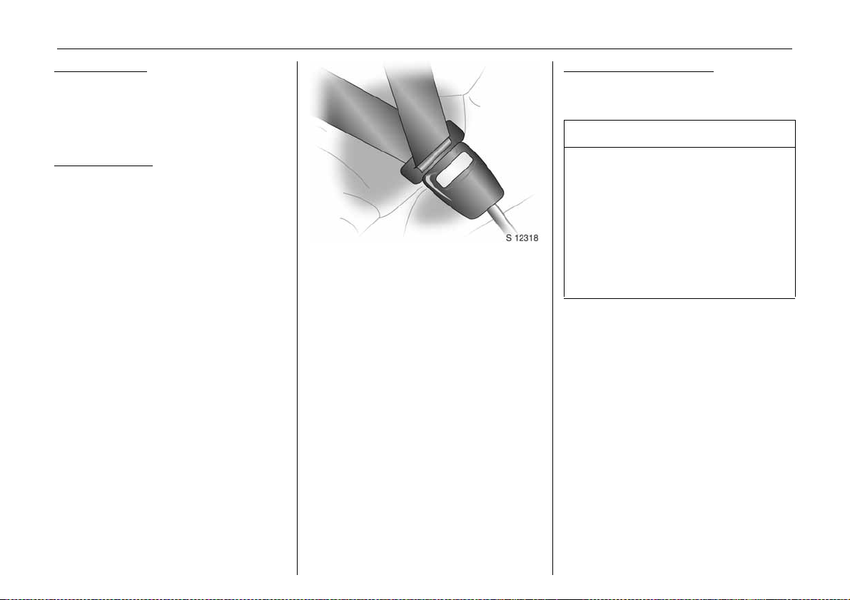
Fitting seat belt:
Draw seat belt smoothly from
inertia reel, guide over shoulder
and enga ge in buckle
The belt must not be twiste d at any point.
The lap belt must lie snugly against the
body.
The backrests must not be tilted back too
far (recommended maximum tilting angle
approx. 25°).
To re lease belt, press red button on belt
buckle.
6 Seat belts – see pages 39 to 43,
airbag systems – see pag e 48,
seat position – see pag e 34.
Page 10
In brief 5
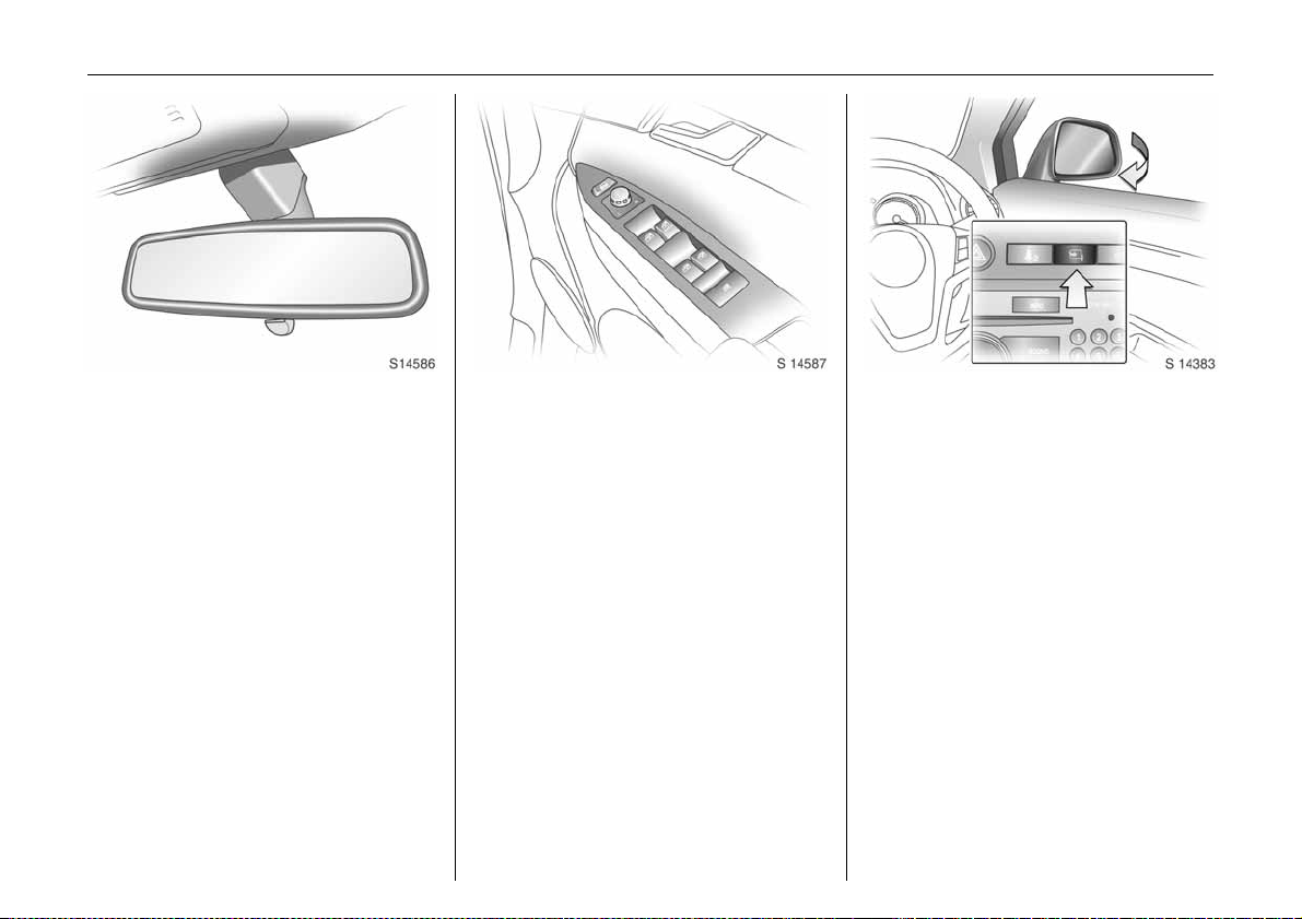
Picture no: s0014522.tif
To adjust interior mirror:
Swivel mirror housing
Swivel lev er on underside of mirror housing
to red uce daz zle a t night.
Take care when driving with interior mirror
adjusted for night vision. Rear view may be
slightly distorted in this p osition.
6 Mirrors - see page 27,
automatic anti-dazzle interior mirror see page 28.
Picture no: s0014523.tif
Electrically adjustable exterior
mirrors:
Four way switch in driver’s door
Move selector switch to L or R; four way
swi tch ad justs co rr e sp ondi n g m irror .
6 Further information,
automatic anti-dazzle exterior mirrors -
see page 27,
heated exterior mirrors - see page 101.
Picture no: s0013448.tif
Fold in exterior mirrors:
Manually: press lightly.
Electrically 3: with starter switch in
positions ACC or ON, press button n and
both mirrors will fold in.
Press button n a g ain; bo th mirrors will fold
to the driving position.
If a fold ed-in electric mirror h as be en
folded out manually, pressing button n
only folds the other mirror out. Pressing
button n a gain folds both mirrors back in.
Fold mirrors back into driving position
before driving the vehicle.
Page 11
6In brief
Page 12

In brief 7
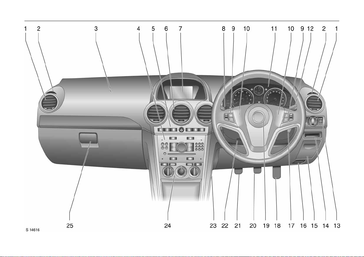
Page
1 Side air v ents .................. .... .... ......... 100
2 Doo r window defroster v ents ..... .... 100
3 Front passenge r’s airbag ...... ......... ..4 8
4 Infotainm ent system . ......... ......... ...... 97
5 Haza rd warning ................. .... ..... ...... 10
Parking distance sensors 3 ... ..... .... 13 8
Desce nt Control System (DCS) ... .... 13 4
Electronic Stability Programme
(ES P) . ........ ......... ......... ......... ......... .... 13 2
Front pa ssenger’s
seat belt reminder 3.......... .... ..... ...... 42
Fold in exterior mirrors 3 ... .... ......... ..26
Control indicator for
Vauxhall alarm system 3 ............... .. 2 5
6 Centre air v ents .............. .... ......... .... 10 0
7 Central information display for tim e,
date, outside temperature,
Infotainment system,
check control 3 ..... .... ..... ........ ......... ..87
Trip computer 3........ ..... .... ......... 77, 84
8 Windscreen and tailgate
wiper and wash .................. .... ..... 11 , 1 2
headlight wash 3.. ......... ........ ......... .. 12
Pa ge
9 Infot ain m e nt sy ste m
remote co ntro l buttons . .... ..... ........... 97
Trip co mp u ter 3 ... ..... ........ ......... .7 7, 84
10 Horn ............. ..... .... ......... ......... ......... .. 11
11 Instruments....... .... ..... ........ ......... ....... 66
12 Headlight flash and m ain beam ..... 10
turn signal lights ....... ...................... .. 10
door-to-door lighting............. .... ..... .. 94
cruise control 3 ......... .... ......... ......... 136
13 Pa rking lights ... ................. ..... .... ..... .. 90
dipped beam ... .... ..... ........ ......... .1 0, 90
automatic dipped beam
activation 3. ..... .... ......... ......... ......... .. 91
headlight range adjustment 3 ...... .. 93
front fog lights .......... .... ......... ......... ..92
fog tail light. ..... ................. ..... .... ..... .. 92
instrument illumination. .... ..... ......... ..94
14 Card ho lder ...... ......... ........ ......... ....... 62
15 Coin storage ..... .... ..... ........ ......... ....... 6 2
Page
16 Bonn et releas e .... ..... ......... ......... ..... 167
17 Starte r switch .................... .... ......... ......9
18 Accelerator pedal ................. ..... .... . 12 3
19 Drive r’s airbag ......... .... .................. ... 48
20 Brake pe dal . ........ ......... ......... ..123, 142
21 Clutch pedal 3......... .... ......... ..123, 124
22 Steering w he el a djustment .. ..... .... ......9
23 Fusebox .. ..... ........ ......... ......... ......... . 178
24 Climate control ... ..... ......... ......... ....... 9 9
25 Glove compartment .... ......... .... 60, 101
Page 13

In b rief8
Control indicators
ABS ( An ti-lock Brake System):
u
se e p age 144.
Trailer indic ator 3:
g
see page 66.
Brake system:
4
see pages 66, 141.
Pa rking d istance sensors 3:
r
see pages 67, 138.
DCS (Descent Control System ):
5
see pages 67, 134.
AWD ( All Wh eel Drive) :
B
see pages 67, 117.
ESP Act ive & W ar ning
7
(Electron ic S tabil ity Prog ramme):
see page 132.
ESP No t Ready :
A
see page 132.
ESP O FF :
J
see page 132.
Automatic headlig ht range
q
adjustment 3:
see pages 67, 93.
Coolant t emperature :
W
see pages 67, 199.
Electronic im mobil iser:
o
see page s 18, 68.
Door open:
9
see page 68.
Engine electronics,
3
tr a nsm is si on e le c tr oni cs 3:
see page s 68, 130.
Airb ag systems 3,
v
belt tension ers:
see page s 40, 48.
Tailgate open:
1
see page 68.
Driv er’s se at b elt re minde r:
X
see page 68.
Turn signal l ights:
O
see page s 10, 68, 91.
Lo w fuel le vel:
Y
see pages 68, 72, 128, 216.
Front fog li ghts:
>
see page s 69, 92.
Fog tai l light:
r
see page s 69, 92.
Headlight main beam:
P
see page s 10, 69, 91.
Low windscreen wash fluid:
G
see page 69.
Wa ter in diesel fuel filter 3:
N
see pages 69, 198.
Change engine oil 3:
C
see page 69.
Pr ehe ating for die sel eng i nes 3:
N
see pages 15, 69.
DPF (Diesel particle filt er ) 3:
I
see page s 69, 131.
Cruise control 3 :
m
see page 136.
Engine oil level 3:
S
see page 69.
Powe r steering:
2
see page 69.
Anti-the ft ala rm syste m ac tivatio n
a
without monitoring of passenge r
compa rtmen t and vehicle tilt 3:
see page 24.
Engine oil pressure :
I
see page 70.
Alternator:
p
see page 70.
Exhaust emissions:
Z
see pages 70, 130.
Wi n ter prog ra m me:
0
see pages 70, 113.
Page 14
In brief 9
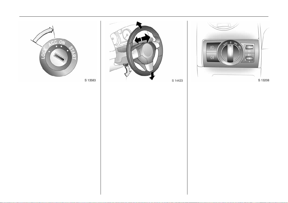
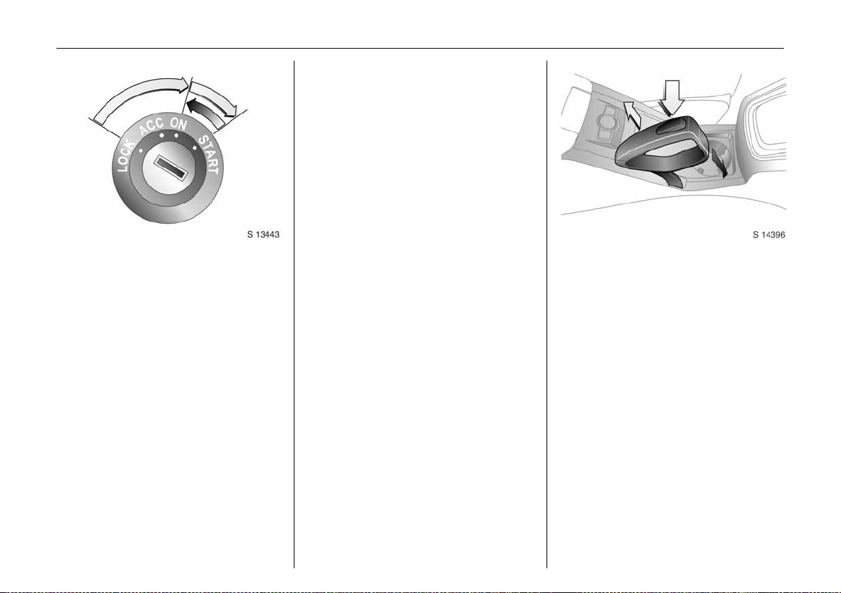
Picture no: s0013583.tif
St e er ing column lock and ig nition:
Turn key to position ACC.
To release lock,
rotate steering wheel slightly
Posit ions:
LOCK = Ignition off
ACC = Steering unlocked, ignition off
ON = Ignition on, with diesel en gine:
preheating
START = Start (transm issio n in neutra l)
6 Starting - see page 15,
electronic immobiliser - see page 18,
parking the vehicle - see page16.
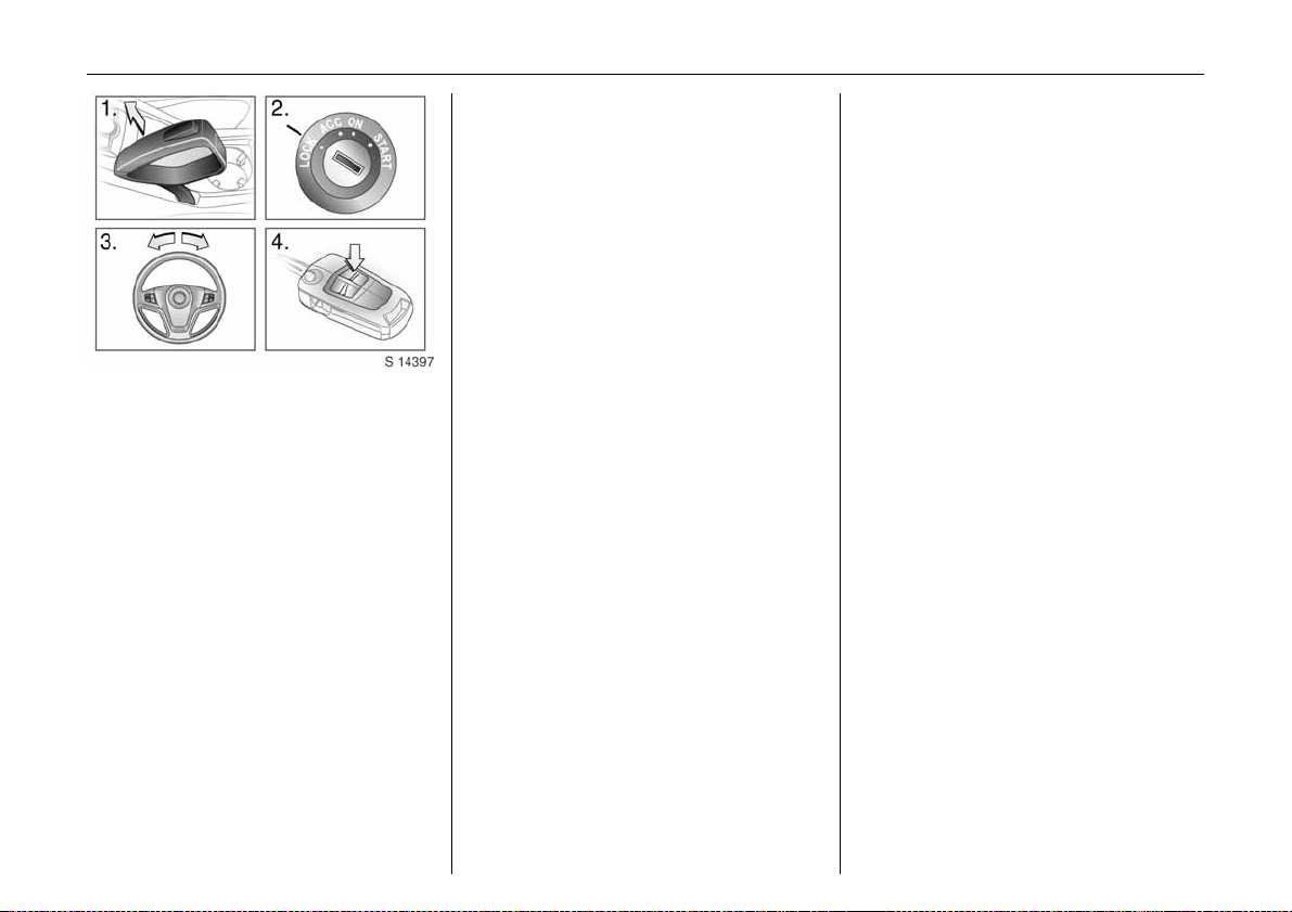
Picture no: s0013777.tif
Steering wheel adjustment:
Mo ve le ver down,
adjust height and distance,
move lever up and engage
Adjust steering wheel only with vehicle
stationary and steering column lock
re l ea s e d.
Push the lever firmly upwards to ensure
that the steering wheel is locked in position.
6 Airbag systems - see page 48.
Picture no: s0013208.tif
Turn li gh t s witch :
J =Off
8 =Parking lights
9 = Dip pe d bea m or
main beam
AUTO = A utomatic dipp ed
beam activation 3
Press button:
> =Front fog lights
r = Fog tail light
6 Headlight warning device - see pag e 88,
further information - see page 90,
hea dlig ht rang e ad ju s tm e nt 3 -
see page 93,
headlights when driving abroad -
see page 96,
daytime running lights 3 - see page 90.
Page 15
In b rief10
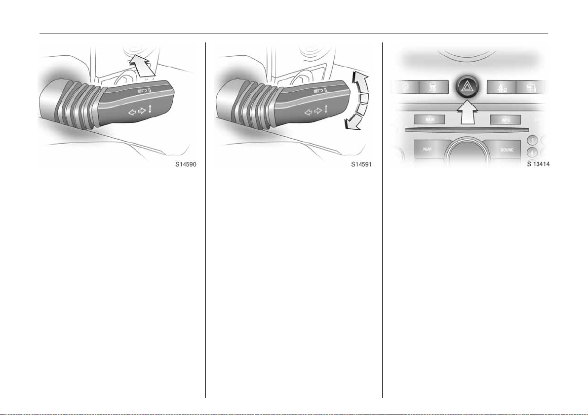
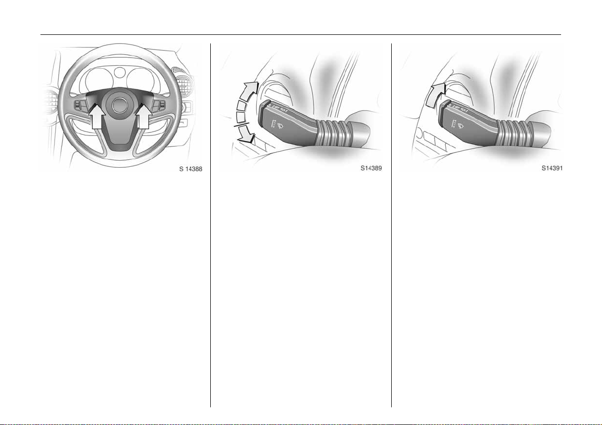
Picture no: s0014526.tif
Headlight flash, main and dipped
bea m:
Headlight
flash
=Pull stalk
towards
st eering wheel
Main beam = Push stalk
forwards
Dipped beam = Pull sta lk b ack
towards
st eering wheel
6 Main beam, headlight flash see page 91.
Picture no: s0014527.tif
Turn sig nal lights:
Stalk in rest position
Upwards = Right turn
Downwards = Left turn
6 Turn signal lights - see page 91.
Picture no: s0013414.tif
Hazard warning lights:
On = Press ¨
Off = Press ¨ again
6 Hazard warning lig hts - see pag e 93.
Page 16
In brief 11
Picture no: s0013249.tif
Activate horn j:
Press either side of the
steering wheel
The horn will sound regardless of starter
switch position.
6 Airbag systems - see page 48,
remote control on steering wheel -
see page 97.
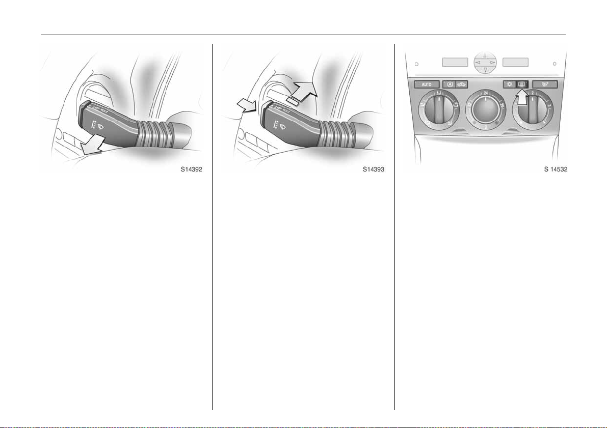
Picture no: s0013251.tif
Windscreen wiper:
Move stalk up wards
J =Off
$ =Timed interval wipe
% =Slow
& =Fast
Press stalk down from position J:
Single swipe.
6 Windscreen wiper - see pag e 88,
adjustable wiper interval - see page 88,
further information - see page s 188, 190,
202.
Picture no: s0013481.tif
Automatic wiping with rain
sensor 3:
Move stalk to automatic wiping
with rain sensor position $
The rain sensor detects the amount of
water on the win dsc reen and automatically
regulates the windscreen wiper.
6 Windscreen wiper - see page 88,
further information - see pages 188, 190,
203.
Page 17
In b rief12
Picture no: s0013482.tif
Operating windscreen and
headlight wash systems 3:
Pull stalk towards steering wheel
6 Windscreen and headlight wash systems
- see page 89,
further information - see pages 188, 190,
203.
Picture no: s0013483.tif
Tailgate wiper and wash systems:
Wiper on = Push stalk forward
Wiper off = Pull stalk back
towards steering
wheel
Wash = Press and ho ld
button
6 Tailgate wiper and wash systems see page 89,
further information - see page s 188, 190,
202, 203.
Picture no: s0014532.tif
Heated rear window,
heated exterior mirrors 3:
Press Ü =On
Press Ü again = Off
6 Air cond itioning - see page 105,
heated rear window, heated exterior
mirrors - see page 101.
Page 18
In brief 13
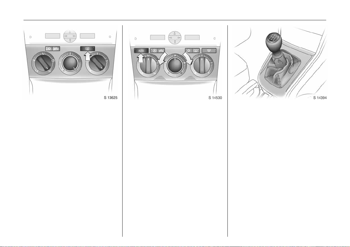
Picture no: s0013625.tif
Drying misted up or iced up
windows:
Set air distribution to position l,
set the tempera ture rotary knob
to red and fan to position 4,
switch on heated re ar windo w Ü
Close centre air vents, open side air vents
and dire ct them to wards the do or windows.
6 Heating, ventilation a nd air condit ion ing
system - see pages 102, 105.
Picture no: s0014530.tif
To set a utomatic mode of
Electronic Climate Control 3:
Press AUTO button,
set temperature using
ro tar y kno b
Open all air vents.
6 Electronic Climate Control (ECC) -
see page 107.
Picture no: s0013612.tif
Man ual tra nsmission:
1 to 5 = 1st to 5th gear
R = R e verse gear
On ly e ngage reverse gear whe n the veh icle
is sta tionary.
Page 19
In b rief14
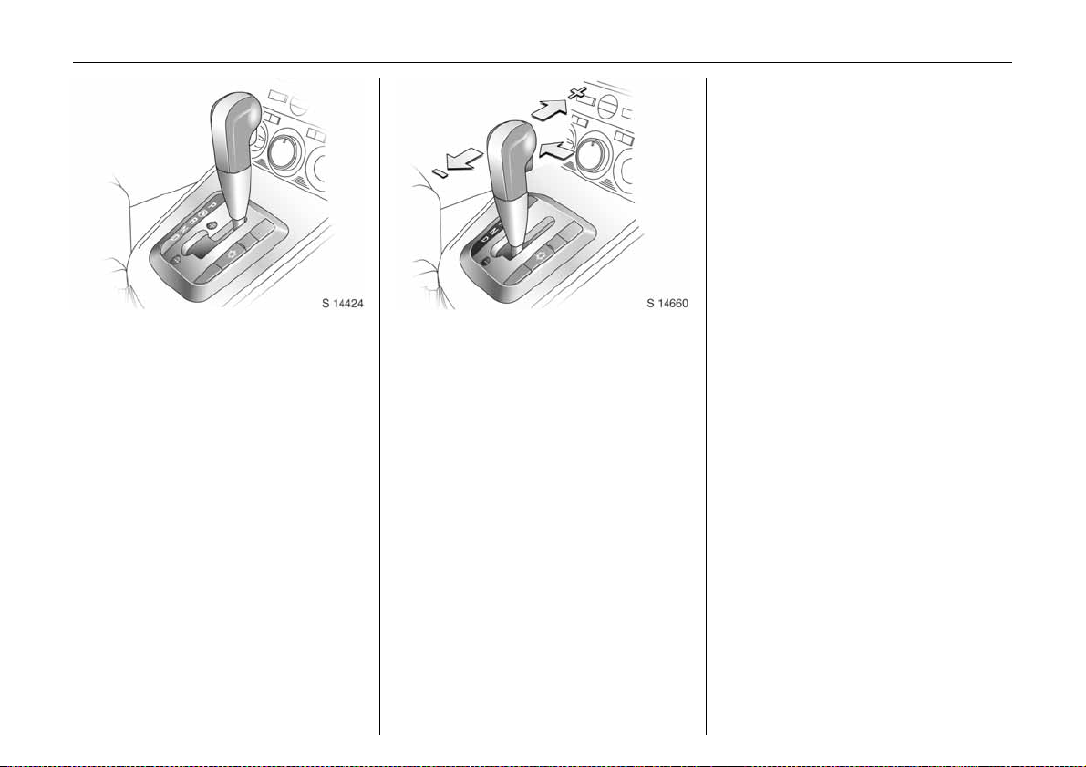
Picture no: s0013252.tif
Automatic transmission 3:
P=Park position
R=Reverse
N=Neutral (idle)
D = Automatic gear selection
Starting is only possible in P or N. To move
from P or N, switch on ignition, depress
footbrake and press selector lever button.
Engage P or R: press selector lever button.
P: Only with vehicle stationary,
first apply handbrake
R: Only with vehicle stationary.
6 Automatic transmission - see page 11 1.
Picture no: s0013629.tif
Manual mode:
<
= Shift to higher gear
] = Shift to lower gear
6 Furthe r information - see pag e 112.
Before starting-off, check:
z Tyre pressures and condition.
z Engine oil level and fluid levels in engine
compartment (see page 195).
z All windows, mirrors, exte rior lighting
and number plates are free from dirt,
snow and ice a nd are operational.
z Objects are securely located and will not
be thrown forward in the event of
sudden braking.
z Seats, seat belts and mirrors are
correctly a djusted.
z All gauges and control indicators.
z Brake operation.
Page 20
Picture no: s0013443.tif
Starting the engine:
Manual transmission in neutral,
Depress clutch and footbrake,
Automatic transmission in P or N,
Do not accelerate
Petrol engines:
Turn key to START and release it
Diesel engines:
Turn key to ON, when preheating
control indic ator N
extinguishes1), turn key to START
an d rel ease it
Key returns automatically to ON position
wh en released .
Start attem pts should not last longer than
15 seconds. If engine does not start, wait
10 seconds before repeating starting
procedu re.
The increased engine speed automatically
returns to normal idling speed as the
engine temperature rises.
Drive at a moderate speed, especially in
cold weather, until normal engine
operating te mperatures have be en
re a ch e d .
6 Electronic immobiliser - see page 18,
diesel fuel system - see page 167,
further information - see page s 123, 125,
127.
In brief 15
Picture no: s0012815.tif
Releasing the handbrake:
Raise lever slightly,
press release button,
lower lever fully
To re duce operating forces, depress
footbrake at the same time.
Do not drive with handbrake on, to avoid
damage to brakes on the rear wheels. Do
not apply handbrake while vehicle is in
motion or as a substitute for the footbrake.
Drive carefully, economically and with the
environment in mind. While driving, do not
do a nything that could distract y ou.
6 Handbrake - see page 143.
1)
Preh eating system switch es on only if o utside
temperature is low.
Page 21
In b rief16
Picture no: s0013599.tif
Parking the vehicle:
Apply handb rake firmly,
close windows,
switch off engine, remove key,
engage steering c olumn lock,
lock v ehicle
6 Further inform ation - see pages 18, 124,
radio frequency remote control -
see page 19,
central locking system - see page 21,
Vauxhall alarm system - see page 23.
Advice when parking:
z Always app ly handbrake firmly. Engag e
first gear on uphill gradients or reverse
gear on downhill gradients. On slopes,
apply the handbrake as firmly as
possible.
z Push key into starter switch before
removing (vehicles with automatic
transmission 3: depress footbra ke and
shift into P before removing key). Turn
steering wheel until lock is felt to engage
(anti-theft protection).
z Sw itch off exterior lights, otherwise the
headlight warning device will sound
when the driver’s door is opened.
z C ooling fans may run on after the engine
has been switched off.
z Do not park vehicle on easily ignitable
surfaces as the hot exhaust system
temperatures could cause the surface to
ignite.
That was the most important
information for your first drive in
your Antara in b rief.
Your vehicle has still more
instrum ents and controls,
possibly also optional equipment.
The rema in ing ch apte rs of the
Owner’s Manual contain
important information on
operatio n, safety and
maintenance as well as a
complete index.
Page 22
Keys, doors, windows 17
Keys, doors, windows
Re placem ent ke ys ... ..... .... ......... ......... 17
Lock cylinders .......... ..... ......... ........ ..... 17
Ca r Pass... .... .... ..... .................. .... .... ..... 17
Key with foldaw ay key section 3 . ..... 17
Electronic immobiliser....... ..... ............. 18
Radio frequency remote control .. ..... 19
Central locking system . ......... ........ ..... 21
Tailgate ....... .... ..... ............. ..... .... .... ..... 22
Mechanical anti-theft locking
sy ste m 3 ... ......... ......... ......... ........ .....
Vauxhall alarm system 3.......... .... ..... 23
Child s afety locks .............. ..... ........ ..... 26
Exterior mirrors......... ......... ......... ......... 26
Interior mirror ....... ......... ......... ........ ..... 27
Electric win dows ... ......... ......... ........ ..... 28
Sun visors.. .... .... .................. ..... .... .... ..... 30
Slide/tilt sunroof 3 ... .............. .... .... ..... 30
23
Replacement keys
The key is a constituent of the electronic
immobiliser. In c ase of loss, replacement
keys can be ordered from your Vauxhall
Authorised Repairer by quoting the key
numb er an d Ve hic le Id e ntificat io n Number
(V IN ) .
Once a new transmitter is coded, the lost
tra nsmitter will not unlock your vehicle.
Orde r ing key s from a Va ux ha ll Aut h o ri se d
Repairer guarantees problem-free
operation of the electronic immobiliser.
Keep spare key in a safe place.
Locks - see page 190.
Lock cylinders
Des igned to fre e-whe el if th ey are
forcefully rotated without the correct k ey or
if the correct key is not fully inserted.
To reset, turn cylinder with the correct key
until its slot is vertical, remove key and then
re -insert it. If the cylinder still free-wheels,
turn the key through 180o and repeat
op er at io n .
Car Pass
The Car Pass contains all of the vehicle’s
data and s hould therefore not be k ept in
the vehicle.
Have your Car Pass to hand when
co nsulting a Va ux ha ll Au th o r ise d Rep airer.
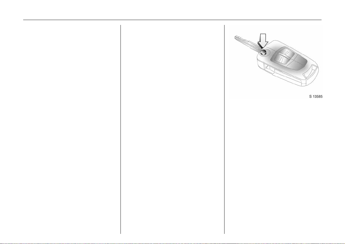
Picture no: s0013585.tif
Key with foldaway key section 3
Press button to extend. Press button to
retrac t; key section audibly engages.
Page 23
Keys, doors, windows18
Not e
The immobiliser does not lock the doors.
Therefore, after leaving the vehicle, always
lock it and switch on the Vauxhall alarm
system 3 - see pages 21, 23.
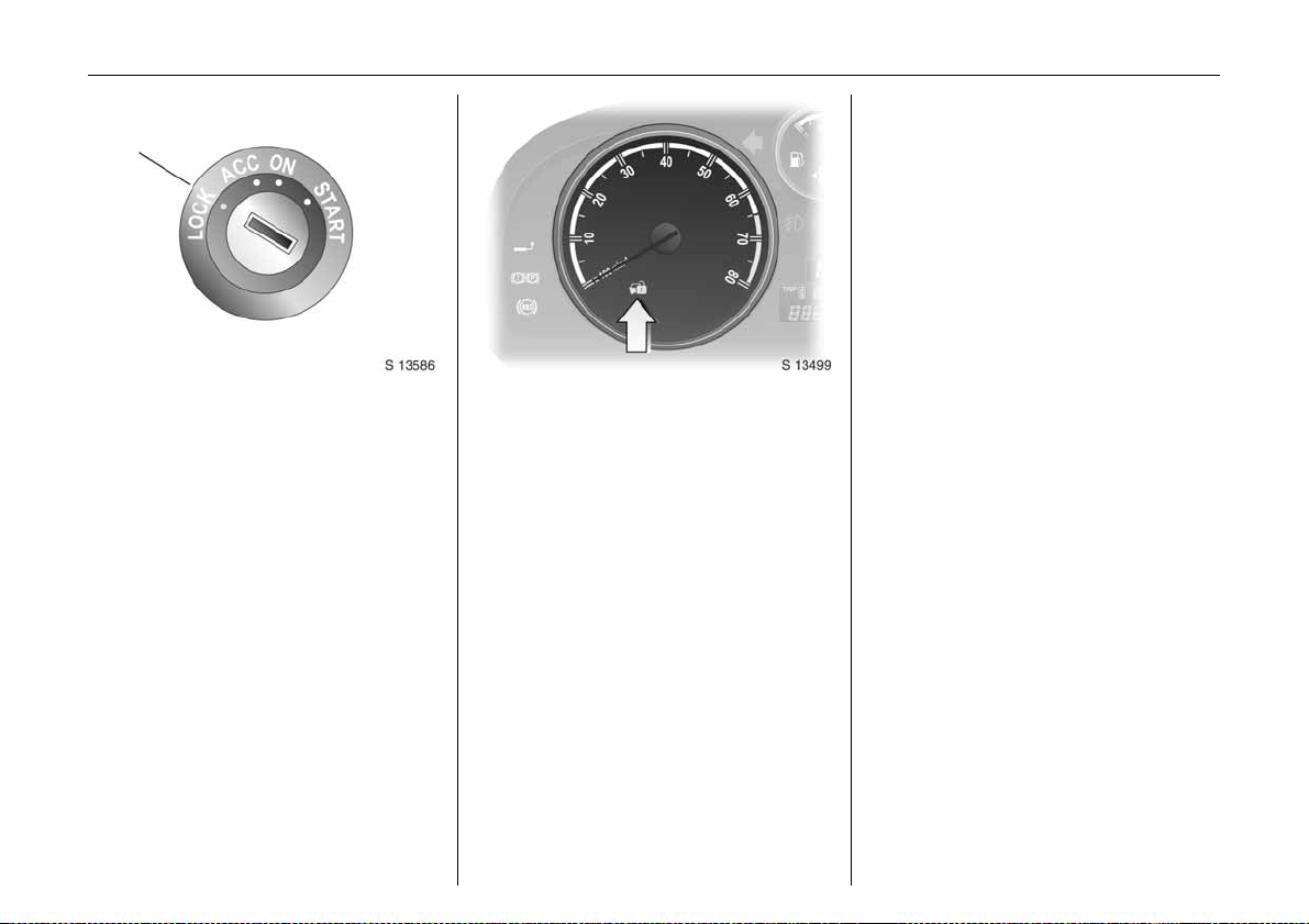
Picture no: s0013586.tif
Electronic immobiliser
The system checks whether the vehicle m ay
be sta rted using the key that has been
in serted. If th e k ey is recogn ised as
"authorised", the vehicle can be started.
The check is carried out via a transponder
housed in the key.
The electronic immobiliser is automatically
activated when the key is turned to LOCK
position and removed from the starter
switch.
Control i ndicator o for immobi liser
Picture no: s0013499.tif
The control indica tor illuminate s when the
ignition is switc hed on, then extinguishes.
If the control indicator stays illuminated
after the ig nition is switched on, there is a
fa ult in the immobiliser system.
z Turn key to LOCK position and remove,
z wait a pproximately two seconds,
z then repeat starting procedure .
If the control indicator fails to extinguish,
try to start the engine using the spare key
and seek the assistance of a workshop.
Page 24
Keys, doors, windows 19
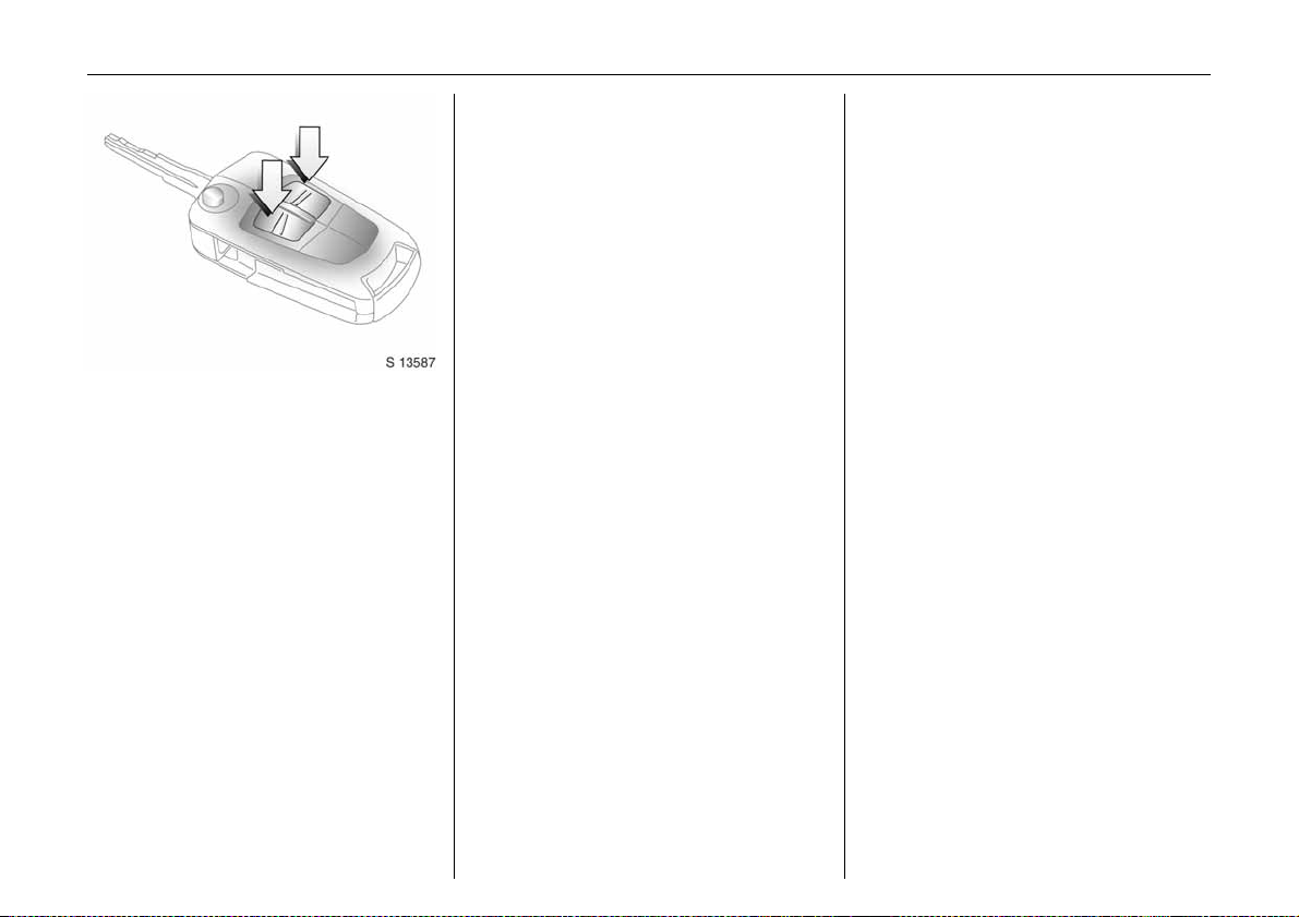
Picture no: s0013587.tif
Radio frequency remote control
The remote control is used to operate:
z Central locking system,
z Mechanical anti-theft locking system 3,
z Vauxhall alarm system 3.
The remote control has a range of approx.
6 metres. The range may be reduced due
to environmental conditions or shadowing
and reflection of the radio w aves.
To opera te the remote control, direct the
rem ote control unit at the vehicle.
Tre at the remote control unit with care:
it should be protected against moisture,
kept out of direct sunlight and should not
be operated unnecessarily.
Do not place heavy objects on the remote
control unit, and avoid dropping it.
The hazard warning lights come on to
indica te that the remote control is
operational.
C entra l locking s yste m
see page 21.
Mechanic al anti -theft locking system 3
see page 23.
Vauxhall alarm system 3
see page 23.
Page 25
Keys, doors, windows20
Fault
If the central locking system cannot be
operated with the remote c ontrol, this may
be due to the follow ing reasons:
z The remote control is out of range.
z The battery voltage of the remote
control is too low. Change the battery in
the remote control unit.
z The remote control has been repeatedly
operated outs ide the ve hicle ’s rece ption
ra nge (e.g. at too great a distance from
the vehicle). The remote control must be
reprogrammed. We recommend you
consult your Vauxhall Authorised
Repairer.
z The system has been overloaded as a
re sult of repeated operation at short
intervals. The power supply is cut-off for
a brief period.
z Inte rference fro m high er p ow er radio
waves from other sources.
Loc k or unlock the doors manually using
the key or central locking switch -
see page 21.
Hav e ca use o f fa ult re me died b y a
workshop.
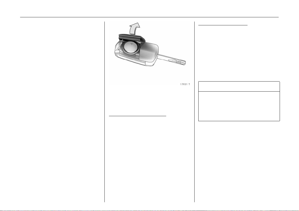
Changing batt ery in remote control unit
Picture no: 17031T.tif
Replace the battery in a ccordance with the
Service Booklet or when the range of the
remote control starts to become reduced.
Key with foldaway key section:
op en cove r by ha nd .
Remove used battery , taking care to avoid
touching the circ uit board to other
components.
Ensure the new battery is installed correctly
with positive (+) side facing up.
Clo se cover, en suring it au dibly en gag es in
the key part.
Key with fixed key section:
insert a small screwdriver in the notch on
the cover and prise it open.
Remove used battery, taking ca re to avoid
touching the circuit board to other
components.
Ensure the new battery is insta lled correctly
with positive (+ ) side facing down towards
the base.
Close cover, ensuring it audibly engages in
the key part.
9 Warning
Used lithium batteries can harm the
environment. Make sure that you dis pos e
of old batteries in accordance with
environmental protection regulations.
Do not dispose with household refuse.
Page 26
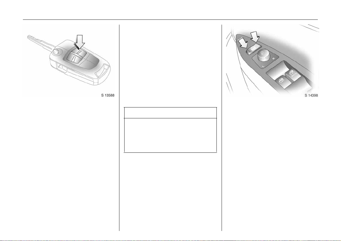
Picture no: s0013588.tif
Central locking system
For front doors, rear doors, tailgate and
tank flap.
To lock:
Press button p on remote control
- or With the doors closed, press central locking
switch m in driver’s door.
The central locking system can be
activated with the windows open.
Always ensure that the doors, bonnet,
tailgate, sunroof 3 and windows are
properly closed and that there are no
passengers left in the vehicle before
locking with the remote control.
To unl oc k :
Press button q on remote control
- or Press central locking switch m in driver’s
door.
If no door is opened within approx.
30 seconds after the vehicle has been
unlocked v ia the remote control, the veh icle
is relocked automatically and Vauxhall
alarm 3 is reactivated.
When button q is pressed, the instrument
panel illuminates for approx. 30 seconds or
until starter switch is turned to the
ACC position.
9 Warning
For safety reasons, the vehicle cannot be
locked or unlocked via the remote control
(and the anti-theft system 3 will not b e
activated) if the key is in the starter
switch.
Keys, doors, windows 21
Picture no: s0013450.tif
C entra l locking s wit ch m
Use the central locking switch to lock or
unlock the doors, tailgate and ta nk flap
from inside the vehicle.
Press the right part of the switch to lock or
the left part of the switch to unlock.
Page 27
Keys, doors, windows22
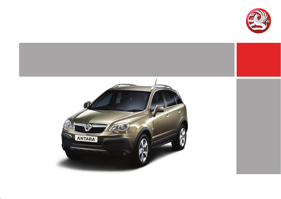
Picture no: s0013776.tif
Tailgate
To unlock and open
Press button q on remote control
- or Press central locking switch m in driver’s
door.
The tailgate is unlock ed together with the
doors and can be opened by operating the
button above the number plate and lifting
the tailgate.
If the tailgate is ope n when the ignition is
switched on, tailgate open control
indicator 1 illuminates in the instrument
cluster.
9 Warning
Ensure there are no obstructions and that
th ere is adeq ua te cle arance w hen
opening the tailgate.
Do not drive with tailgate open or ajar,
e.g. when transporting bulky objects,
sinc e toxic exhau s t gases could
penetrate the vehic le interior.
If driving with tailgate open is necessary,
set fan to highest speed, open all air
vents, close windows and ensure air
recirculation mode is off, to allow entry of
outside air.
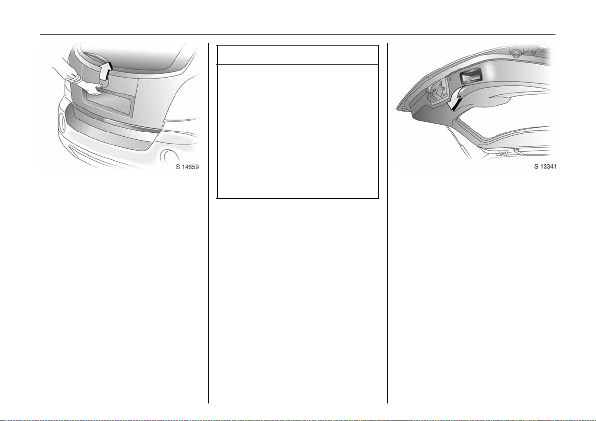
To close and l ock
Picture no: s0013341.tif
There is a handle on the inside of the
tailgate for closing the luggage
compa rtment.
Close tailgate by pushing it down so it
latches securely. Ensure tailgate is fully
closed before driv ing.
To lock tailg ate, together with the doors:
Press button p on remote control
- or Press central locking switch m in driver’s
door.
If the ignition is switched on, the tailgate
open control indicator 1 extinguishes in
the instrument cluster.
Page 28
Keys, doors, windows 23
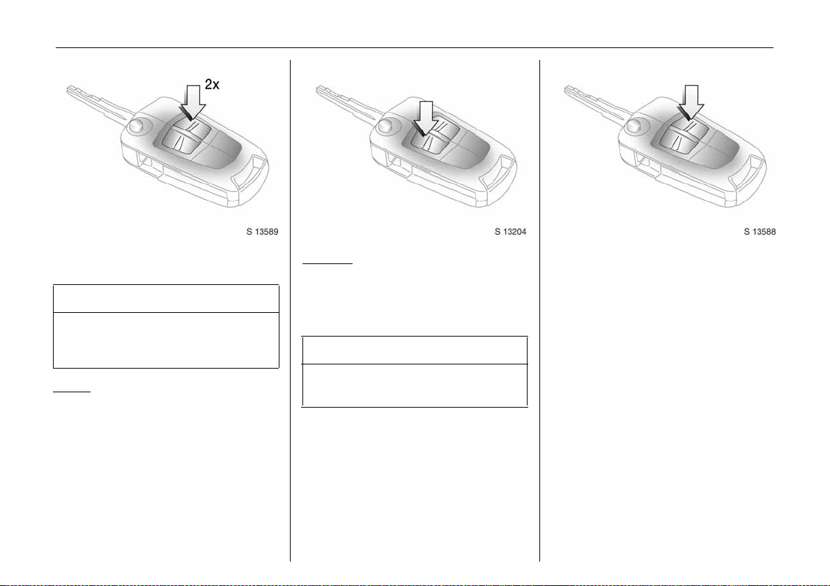
Picture no: s0013589.tif
Mechanical anti-theft locking
system 3
9 Wa rning
Do not use the system if there are people
in the vehicle. The doors cannot be
unlocked from inside.
To lock:
All doors and the tailgate must be closed;
press button p on remote control again
wi thin 3 seco nd s a fter locking
- or Turn key in driver's door lock towards rear
of vehicle aga in within 3 seconds after
locking, then turn it back to the vertical
position and remove.
Lock buttons on all doors are positioned
such that doors cannot be opened.
To un l o c k:
Picture no: s0013204.tif
Press button q on remote control
- or Turn key in driver's door lock towards front
of vehicle, then turn it back to the vertical
position and remove.
9 Warning
Unlocking is not possible in any other
way, so keep spare key in a safe place.
Picture no: s0013588.tif
Vauxhall alarm system 3
The sy st e m monit ors:
z Front and rear doors.
z Tailgate, bonnet.
z Starter s witch .
z Passenger compartment 3.
z Vehicle tilt, e.g. if it is raised 3.
z Siren power supply 3 .
Page 29
Keys, doors, windows24
9 Wa rning
Do not use the system if there are
passengers in the vehicle. The doors
cannot be unlocked from the inside when
the alarm is activated and when the
mechanical anti-theft locking system is
activated .
The remote control unit is used to operate
the anti-theft alarm system.
To activate
Always ensure that the doors, bonnet,
tailgate, sunroof 3 and windows are
properly closed and that there are no
passengers left in the vehicle before
activating a nti-theft alarm system.
Press button p on remote control
- or Lock driver’s door by turning key in door
lock towards rear of vehicle then turn it
back to the vertical position and remove;
z Hazard warning lights flash once,
z All do or s ar e lo c ked ,
z Anti-theft system is activated after
approx. 30 seconds.
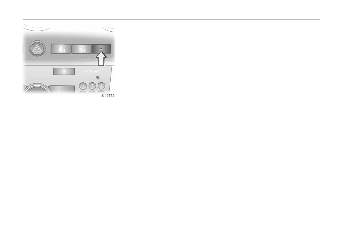
Confirm that the control indicator starts
Picture no: s0013730.tif
flashing slowly, after illuminating for
approx. 30 seconds, to show that the anti-
theft system has been activated.
If button p is pressed again, the anti-theft
alarm system will activate automatically,
bypassing the 30 second delay. This will
also activ ate the mechanical anti-theft
locking system.
If the hazard warning lights do not flash on
activation or the control indicator flashes
quic kly, this may indicate that a door, the
tailg ate or the bonnet is not fully closed.
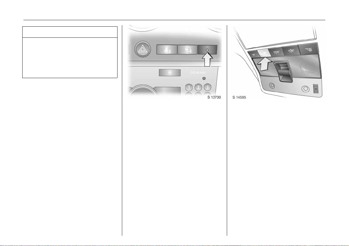
Act ivat ion without monitoring of
Picture no: s0014556.tif
passenger c ompartment a nd vehicle tilt 3
Switc h on when, for e xample, animals are
to be left in the vehicle.
1. Close tailgate and bonnet.
2. Press button a in the roof lining.
Control indicator a illumina tes in
yellow in the instrument cluster.
3. Close doors.
4. Switch on anti-theft alarm system.
Control indicator for anti-theft alarm
system illuminates. After a 30 second
delay, the system is activated without
monitoring of the passenger
compartment or vehicle tilt.
Control indicator a remains
illuminated in the instrument cluster
until the system is switched off by
pressing button a again.
Page 30
Keys, doors, windows 25
Cont rol indica tor for anti -theft alarm
Picture no: s0013730.tif
system 3
The c ontrol indicator illuminates to show
th at the system is operatio nal wh en th e
doors are locked with the remote control or
the key. When the doors are unlocked with
the key or remote control, the control
indicator extinguishes.
To deactivate
Press button q on remote control
- or Unlock driver’s door by turning key in door
lock towards front of vehicle, then turn it
back to the vertical position and remove:
z Haz ard warning lights flash twice,
z All doors are unlocked,
z Anti-theft system is deactivated .
If the dr iver’s door is not op ened, or th e
engine is not started within 30 seconds of
deactivation, all doors are automatically
relo cke d an d the sy ste m is reac tiv ated.
If the alarm has been trigg ered, the hazard
warning lig hts will not flash upon
deactivation.
Note
The anti-theft alarm system cannot be
deactivated in any other way, so keep a
spare key in a safe place.
Changes to the vehicle interior, such as the
use of seat covers, could impair the
function of passenger compartment
monitoring 3.
Alarm
While the alarm system is switched on, the
alarm can be triggered, indicated by:
z an acoustic signal (horn) and
z a visual sig nal (exterior lights).
The number and duration of the alarms are
legally established.
The alarm is stopped by pressing q or p
on the remote control or by unlocking
the driver’s door with the correct key.
The anti-theft alarm system is deactivated
at the same time.
Ala rm siren wit h integrated b attery 3
The alarm siren monitors the on-board
voltage network and triggers an ala rm if
this network is manipulated (e.g. if the
vehicle’s ba ttery is disconnected by
unauthorised persons). The alarm siren has
its own powe r supply and is therefore not
dependent on the vehicle’s battery.
If the vehicle’s battery is to be
disconnected (e.g. for maintenance w ork),
the alarm siren must be deactivated as
follows: switch the ignition on then off,
disconnect the vehicle’s battery within
15 se co nds.
To switch off alarm siren:
Switch ignition on then off.
Page 31

Keys, doors, windows26
Picture no: s0012858.tif
C hil d saf e ty locks
9 Wa rning
Use the child safe ty locks whene ver
children are occupying the rear seats.
Disregard may lead to injuries or
endanger life. Vehicle passengers must
be informed accordingly.
To engage lock , open d oor, insert key into
child safety lock and turn lock from the
vertical to the horizontal position. Door
cannot then be opened from inside.
To unlock door while child safety lock is
activated, pull up lock button and open
door from outside. Do not pull inside door
handle while child safety lock is activated.
Picture no: s0014523.tif
Exterior mirrors
Electrically adj ustable exterior m irrors
Adjust with the four way switch in driver’s
door: move selec tor switch to L or R;
four way switch adjusts corresponding
mirror.
The mirror glass swivels in the same
direction as the activ ation of the four way
swi tch .
Heated exterior mirrors 3 - see page 101.
Fold in ex terior mirr ors
Picture no: s0013448.tif
Manually: the exterior mirrors can be
folded in by pressing lightly on the outside
of the mirror housing.
Electrically 3: with starter switch in
positions ACC or ON, press button n and
both mirrors will fold in.
Press button n a g ain; bo th mirrors will fold
to the driving position.
If a fold ed-in electric mirror h as be en
folded out manually, pressing button n
only folds the other mirror out. Pressing
button n a gain folds both mirrors back in.
Fold mirrors back into driving position
before driving the vehicle.
Page 32

Keys, doors, windows 27
For the safety of pedestrians, the exterior
Picture no: s0013687.tif
mirrors will swing out of their normal
mounting position in the event of an
accident-lik e im pact.
As exterior mirrors are convex, objects are
closer than they appear. Use interior mirror
to judge size and distance of objects.
Do not scrape ice from exterior mirrors or
force them if frozen. Use a d e-icer.
Automat ic anti-daz zle ext erior mirrors 3
Picture no: s0013590.tif
Dazzle is automatica lly reduced.
Exte rior mirrors dim to reduce glare
automatic ally in conjunction with the
automatic anti-dazzle interior mirror 3 -
see p age 28, Fig. S14381.
Picture no: s0014522.tif
Interior mirror
To adjust interior mirror, swivel mirror
housing.
Swivel lever on underside of m irror housing
to reduce d azzle at night.
Take care when driving with interior mirror
adjusted for night vision. Rear v iew may be
slightly distorted in this position.
Page 33

Keys, doors, windows28
Picture no: s0013260.tif
Autom atic a nti-daz z le interior mir ror 3
Dazzle is automatically reduced.
With the ignition off, the mirror does not
dim.
Press button on mirror housing to turn
function on. Button will illuminate.
Press button again to turn off.
There are two light sensors in the mirror
housing. To avoid interference and loss of
func tio n , d o not co v er the se nsors or hang
anything on the mirror.
Electric w in dows
9 Warning
Care m ust be taken when operating the
electrically operated door windows.
There is a risk of injury, particularly for
children, and a danger tha t articles could
become tra pped. Vehicle passengers
must be informed accordingly.
If there are children on the rear seats,
press the switch in the driver’s door to
lock rear window operation. Rear
windows can then only be operated via
th e driver’s door switches.
Keep a close watch on the windows when
closing the m. Ensure that nothing
becomes trapped in them as they move.
Before leaving the vehicle, remove the
ignition key in order to prevent
unauthorized operation.
Operational with key in starter switch
Picture no: s0014524.tif
positions ACC or ON. If key is in LOCK
position or removed, windows can be
ope rated for 1 0 minutes or u ntil d riv er’s
door is opened.
Operat e d via four switches locate d in th e
driver’s door.
For increme ntal operation, briefly pull or
press the switch.
For a utomatic 3 opening or closing, p ull or
press the switch longer. Pull or press the
switch again to stop the movement.
Page 34

Safety func tion
If the window glass encounters resistance
above the midd le of the window during
automatic closing, it will stop imme diately
and will be opened again.
In the event of difficulty due to frost or the
lik e, press the relevant window switch
several times until the window is closed.
Keys, doors, windows 29
Additional switches are located in the front
Picture no: s0013608.tif
passenger’s door and the rea r doors.
The rear windows do not open fully.
Child safety system for rear windows
Picture no: s0014525.tif
Press z switch in driver’s door to lock rear
window operation.
With the lock on, rear passenger windows
can only be operated via the switches in
th e driver’s doo r.
Page 35

Keys, doors, windows30
Picture no: s0013447.tif
Sunvisors
Use the sunvisor to protect from glare by
pulling it up, down or swivelling it to the
side.
Sunvisors have vanity mirrors and a ticket
holder 3 on the rear.
When the vanity mirror covers are opened,
the sunvisor light 3 will illuminate.
Picture no: s0013609.tif
Slide/tilt sunroof 3
Operated via switch in roof lining when the
starter switch is in positions ACC or ON.
With key in LOCK position in the starter
switch or removed, the slide/tilt sunroof can
be a djusted for up to 10 m in utes or until a
door is opened.
For increme ntal operation, briefly press the
button. For automatic opening or closing,
press and hold the switch.
To open
Press switch rearwards; it will op en
automatically unless the switch is pressed
again in another direction, or released.
To close
Press and hold switch forwards. Release
switch when sunroof reaches desired
position.
To til t
Press and hold switch upwards. Release
switch when sunroof reaches desired
position.
To return sunroof to its original position,
press and hold switch downwards. Release
switch when sunroof reaches desired
position.
Page 36

Note
z If the top of the sunroof is w et, tilt it to
allow water to run off before opening the
sunroof.
z When carrying a roof load, check the
clearance of the sunroof, to avoid
damage.
9 Wa rning
Care must be taken when op erating the
sunroof. Do not place any objects or
body parts in the sunroof opening.
Keep sunroof clear of debris. Do not
place heavy objects on or around
sun roof.
When leaving the vehicle unattended,
ensure the sunroof is fully closed.
Keys, doors, windows 31
Page 37

Seats, interior32
Seats, interior
Fron t s ea ts ...... ..... .... ......... ......... ......... 32
Re ar seats .... .... ......... ......... ......... ......... 37
Safety be lts ................... .... ......... ......... 38
Child restraint systems 3 .......... .... ..... 43
Airbag system s .... ......... ......... ........ ..... 48
Storage .... .... .... ..... .................. .... .... ..... 55
Drink holders ........ .... ..... ......... ........ ..... 63
Ashtrays 3....... ..... .... .................. .... ..... 63
Warning triangle ¨ 3, First-
aid kit +3......... ......... ......... ........ .....
Power outlets .. ..... .... ......... ......... ......... 64
As sist grips ............... ..... .... ......... ......... 65
64
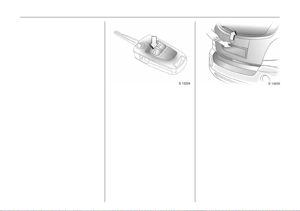
Picture no: s0013335.tif
Front sea ts
9 Warning
Never adjust seats whilst driving as they
could move uncontrollably.
Adjust seat lo ngi tudinally
To adjust, p ull the handle on the front seat,
slide the seat and release the handle.
Adjusting front seat b ackrests
Picture no: s0014613.tif
To adjust, lift the release lever, move seat
backrest to suit seating position and lock in
position when the lever is released.
Do not lean on the seat backrest whilst
adjusting it.
Page 38

Adjusting the lumbar support 3
Picture no: s0013261.tif
To adjust, turn the handwheel whilst
relieving the load on the bac krest.
Adjust lumb ar support to suit pe rsonal
requirements.
Seats, interior 33
Electrica lly a djustabl e front seat 3
9 Warning
Care must be ta ken when operating
electrically adjustable seats. The re is a
risk of injury, p articularly for children and
a danger that articles could become
trapped.
Keep a close watch on the seats when
adjusting them .
Vehicle pa ss enge rs m ust be in form ed
accordingly.
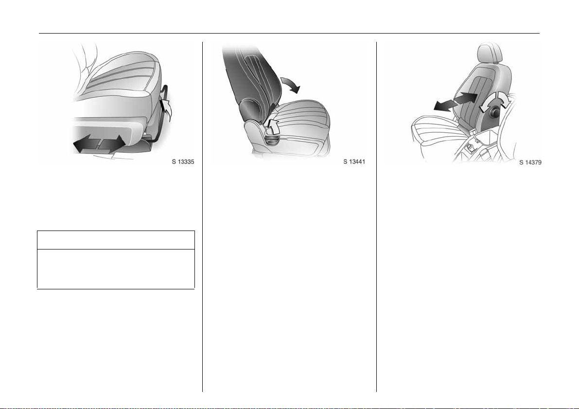
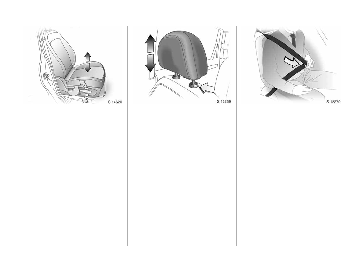
Picture no: s0014614.tif
Adjusting seat height 3
To adjust, op erate lever o n sid e of seat.
Lever pumping action
up war d: raises se at
downward: lowers seat
Page 39

Seats, interior34
Seat position
Adjust driver’s seat such that, with the
driver sitting upright, the steering wheel is
held in the area of its upper spokes with the
driver’s arms slig htly bent.
Slid e front passenger’s seat as far back as
it will go.
The se at backrests must not be tilted back
too far (recommended max imum tilting
angle approx. 25°).
9 Warning
Adjustment
Picture no: s0013257.tif
The se at position can be adjusted by
means of switches on the outboard side of
the seat.
Adjusting the longitudinal position:
Move front switch forwards/backwards.
Height adjustment:
To adjust height of front part of seat
cushion, push front part of switch up/down.
To adjust height of rear part of seat
cushion, push rear part of switch up/down.
To adjust height of entire seat cushion,
push both front and rear parts of switch
up/dow n.
Seat backrest adjustment:
Picture no: s0013461.tif
Move upper part of rear switch forwards/
backwards.
Operate switch until desired seat position is
re ached . Seat position - see next column.
After adjusting the seat, a djust height of
seat belt - see page 43.
The seat backrest must not be tilted back
too far (recommended maximum tilting
angle approx. 25°).
Important: Do not sit nearer tha n
10 in ch es (25 cm) fro m th e s teering
wheel, to permit safe airbag deployment.
Disregard ca n lead to injuries which c ould
be fatal. Vehicle passengers must be
informed accordingly.
Page 40

Head re strai nts
Picture no: s0013259.tif
To adjust head restraint height, press
release button, adjust height to suit then
release the button.
Pull head restraint up to raise. Push head
restraint down while pressing the release
button to lower the head restraint.
Ac tiv e h ead restraints 3
In the event of a rear-end impact, the
active head restraints automatically tilt
forwards. The head is more effectively
supported by the head restraint and the
danger of whiplash in the neck area is
re duced.
Do not a ttach objects or components that
are not approved for your vehicle to the
head restraints. These affect the protective
effect of the head restra ints and ca n be
propelled through the vehicle in an
uncontrolled m anner if the driver brakes
hard or an accident occurs.
Seats, interior 35
Picture no: 17055T.tif
Head restraint position
For m aximum protection, the middle of the
head re stra int should be at eye level. If this
is not possible for extremely tall persons,
set to highest position, and set to lowest
position for extremely small persons.
9 Warning
Disregard ca n lead to injuries which c ould
be fatal. Vehicle passengers must be
informed accordingly before moving
away.
Page 41

Seats, interior36
Picture no: s0014545.tif
Front sea t arm rest 3
Th e armres t can be s lid forw ards. Pull up
and hold upper lever and slide the arm rest
forwards.
To return armrest to its rearmost position,
slide it back until it latches into position.
Cons ole box in fro nt a rmres t - se e pag e 61.
Folding down the p assenger’s sea t 3
Picture no: s0013441.tif
Push front passenger’s seat head restraint
all the way down - see page 35.
Slide front passenger’s seat as far back as
it will go.
Fold seat forwards by lifting backrest
re lease lever and folding ba ckrest down
onto s ea t c u shi on .
To raise the seat, lift backrest relea se lever
and p ush backre st to upright position.
Pu sh and p ull on s eat ba ckres t to ensure it
is locked, thus avoiding excessive forward
movement in the event of a collision.
9 Warning
If long er objects, e.g . skis, are to be
carried on the back of the front
passenger’s seat backrest, ensure they
are n ot in the area in which the front
passenger’s airbag inflates or in the area
between the seat ba ckrest and the
vehicle body. In the event of a collision,
such objects may be thrown through the
vehicle.
The load must not hinder handbrake
operation or gearshifting.
Disregard of these notes can lead to
injuries which ma y be fatal.
Page 42

Picture no: s0013446.tif
Rear seats
To adjust backrests, lift release lever
located on top of backrest and move
backre st forwards or backwards to desired
position.
Do not lean on s ea t backre st whilst
adjusting it or ma ke adjustments while the
vehicle is moving.
When folding the rear seat backrests,
ensure the seat belts are unbuckled.
Folding rear seat ba ckre sts
Picture no: s0013669.tif
The luggage compartme nt can be
enlarged by folding the rear seat b ackrests
onto the seat cushions.
To fold rear seat backrests separately,
unbuckle all three rear seat belts and
ensure front seats are not in reclined
position.
Push head restraints all the way down, lift
backrest release lever and fold backrest
forward s and down onto seat cushion.
Do not allow passengers to sit on folded
backrest, or place any unrestra ined loads
on it.
Seats, interior 37
9 Warning
When folding the backrest, use caution beware of moving parts.
Safety net 3 - see page 56.
Restoring rear seat back rests
Lift and push backrest up a nd backwa rds
to restore it to its original position. Ensure
backrest latches into plac e by pushing top
of back rest and pulling it forwards again.
9 Warning
Ensure that the backrest returns to its
correct position - see page 34.
Never adjust the rear seat backrests
whilst the vehicle is moving. They could
move in an unc ontrolled manner when
the lever has been pulled.
Page 43
Seats, interior38
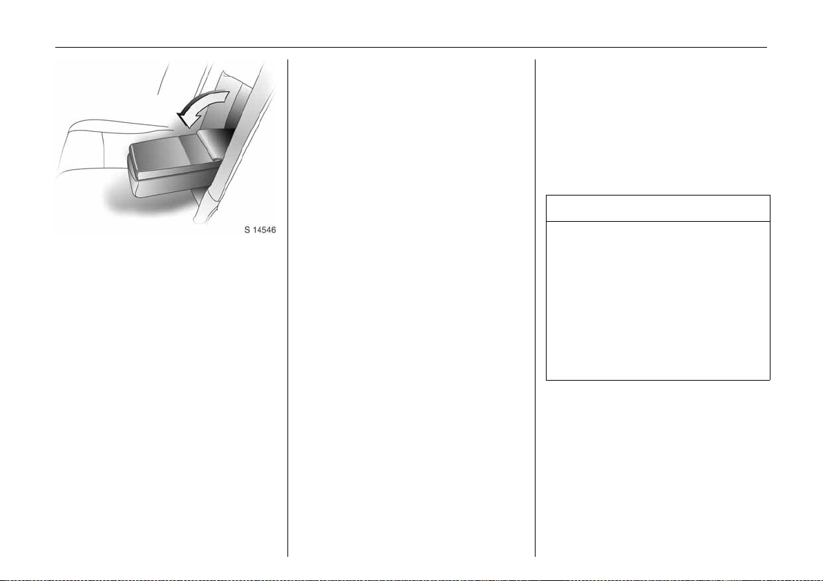
Rear seat ar mrest 3
Picture no: s0014546.tif
Th e armres t can be folded down.
If the rear centre seat is being used or the
rear seat backrests are be ing folded down,
fold armrest upwards.
Console box in rear arm rest - see page 61.
Safety belts
Three-stage restraint system
The system comprises:
z Three-point seat be lts.
z Be lt tensioners, with load limiters, on the
fro nt se ats.
z Airbag systems for driver, front
passenger and rear outboard seat
occupants.
Th e thre e stag es are a ctivated in sequence
depending on the seriousness of the
accident:
z The automa tic seat belt locking devices
prevent the belt strap from be ing pulle d
out and thus ensure that the vehicle
occupants are re tained in their seats.
z The front seat belt buckles are pulled
downwards. As a result, the seat belts
are instantaneously tightened and the
occupants are made aware of the
deceleration of the vehicle at a very early
stage. This reduces stress placed on the
body.
z The airbag system is additionally
trig gered in the event of a serious
accident involving a frontal impact, and
forms a safety cushion for the driver and
front passenger. In the event of a side-
impact, the side airbag system 3
protects the occupants in the front of the
vehicle, and the curtain airbag system
protects both front and rear outboard
seat occupants.
9 Warning
The airbag system serves to supplement
the three-point seat belts and belt
tensioners. The seat belts must therefore
always be worn.
Disregard of these notes can lead to
injuries which ma y be fatal. Vehicle
pas se ngers must be inform ed
accordingly.
Be sure to read the descriptions of all the
restraint systems on the following pages.
Page 44

Seats, interior 39
Three-point s eat belts
The front and rear seats are equipped with
three-point seat belts with automatic
retractors and locking devices, allowing
freedom of body movement w hen the
vehic le moves at a constant speed,
although the spring-tensioned belts are
always a snug fit.
T h e b elt h as a “ v e h ic le s en siti v e re tra c t or”
which is designed to lock during heavy
acceleration or de celeration in a ny
direction.
9 Warning
Always we ar your seat belt, also in urban
traffic and when you are a rear seat
passenger. It can save your life!
Pregnant women too must always wear a
seat belt, keeping the lap belt low and
snug on the hips and pelvis (not the waist
or abd omen, where actuating b elt
te ns ione rs could cause serious injury i n
the event of a collision).
In the event of an accident, persons not
wearing seat belts endanger the ir fellow
occupants and themselves.
Control indicator X for driver’s seat belt
re minder - see pa ge 6 8.
Control indicator k for front passeng er’s
seat belt reminder 3 - see page 42.
Seat belts are designed to be used by only
one person at a time. They are only
suita ble for children a ged up to 12 or
smaller than 150 cm if used in conjunction
with a child restraint 3.
For children up to 12 years of a ge, we
recommend the Vauxhall child restraint
system 3 - see page 43.
Page 45
Seats, interior40
Belt force limiters
Load limiters on the front seats reduce the
impac t o n the seat occu pant’s bo dy fr om a
tensioning b elt, in the event of a severe
frontal collision. The belt force is controlle d,
to reduce the risk of b elt-inflicted injury.
Inspection of belts
Periodically inspect all parts of the belt
system for damage and to make sure they
are functioning properly.
Have damage d parts replaced. Afte r an
accident, belts and trig gere d belt
tensioners must b e replaced by new ones.
Do not perform any alterations on the
be lts, the ir anchorages , the au tom atic
retractors or the belt buckles.
Make sure that belts are not dam aged or
trapped by sharp-edged objects.
Belt tensione rs
Picture no: s0011739.tif
The seat belt systems on the front seats
incorporate belt tensioners housed in the
belt buckles and seat belt retractors.
In the event of frontal collisions or side-
impacts of a certain severity, belt buckles
and seat belt retractors tighten the seat
belts; the shoulder and lap belts are
instantaneously tighte ned to fit the
occupant’s body more snugly.
The belt buckles and seat belt retractors
will remain locked after actuation (where
some noise will occur and smoke may be
re l ea s e d) .
Belt tensioners are not d esigned to activate
in the event of rear-im pacts, minor sideimpacts, rollovers or minor frontal
collisions.
Actuation of belt tensioners
The belt tensioners actuate only once and
must be replac ed by a workshop after
activation.
9 Warning
The belt tensioners are operational only
when control indicator v is unlit.
If the control indicator does not flash
briefly whe n the ignition is on, stays lit,
illuminates or flashes whilst driving, the
belt tensioners or the airbag systems may
not function correctly.
Have both systems inspected by a
workshop.
The seat belts remain fully operational
even when the belt tensioners have been
actuated.
Page 46

Seats, interior 41
Belt tensioners control indicator
Picture no: s0013500.tif
The seat belt tensioners are monitored
electronically together with the airbags,
and their operational readiness shown by
the red control indicator v in the
instrument clus ter.
When the ignition is switched on, the
control indicator flashes several times then
e xting uis h es. If it do es no t flash, stays lit,
illuminates or flashes whilst driving, there is
a fault with the belt tensioners or in the
ai rba g sy ste ms. The s ystems mig ht not
therefore be triggered in the event of an
accident (see also page 52).
9 Wa rning
The system’s integrated self-diagnostics
allows faults to be quickly remedied.
Important
z Accessories not released for your v ehicle
type and other objects must not be fixed
or placed within the action zone of the
belt tensioners, as they may result in
injury if the be lt tensioners are triggered.
z Do not make any modifications to the
components of the belt tensioners, as
this may result in unintended actuation
of the belt tensioners, rendering the
vehicle unroadworthy and ca using
serious personal injury.
9 Warning
Improper handling (e.g. removal or
installation) can activate the belt
tensioners – risk of injury.
z The belt tensioner and airbag system
control electronics can be found in the
centre console area. In order to avoid
malfunctions, do not store magnetic
objects in this area.
z When using the rear seats, ensure that
the front seat belt components are not
damaged by shoes or other objects.
Avoid dirt getting in the retractors.
z The belt tensioners only actuate once,
indicated by continuous illumination of
control indicator v in the instrument
cluster. Deployed belt tensioners must be
replaced by a workshop.
z When disposing o f th e veh icle, observe
the app licable safety regulations. Have
the ve hicle d ispos ed of b y a disposal
company which reuses vehicle parts.
Have the cause of the fault remedied by
a workshop.
Page 47

Seats, interior42
Using the belts
Picture no: s0011650.tif
Fitting the belt
Pull the belt out evenly from the retractor
and guide it over the shoulder, m aking
certain that it is not twisted.
Insert the la tch plate into the buckle.
The se at backrest must not be tilted back
too far (the recommended m aximum tilting
angle is approx. 25°).
The lap belt must not be twisted and must
fit snugly across the body. Tension the belt
frequently whilst driv ing by tugging the
diagonal part of the belt.
Picture no: s0011735.tif
9 Warning
On pregnant women in particular,
the lap belt must be positioned as low a s
possible across the pelv is in order to
prevent pressure on the abdomen.
Keep knees pointing straig ht forward so
that driver’s side knee bolsters can help
prevent submarining under the seat belt in
the event of a collision.
Bulky clothing prevents the belt from fitting
properly. The belt must not rest against
hard or fragile objects in the pockets of
your clothing (e.g. ballpoint pens, keys,
spectacles) because these could cause
injury in the event of a collision. Do not
place an y object s ( e.g . h andbags) between
the belt and your body.
Front p ass enge r’s seat belt r em inde r k 3
Picture no: s0013540.tif
Illuminates for approx. 4 seconds when
ignition is switched on.
When the engine is running, if the front
passenger’s seat is occupied and the belt is
not enga ged, the control indicator will
flash for approx. 90 seconds and then
illuminate until the belt is fastened
correctly (control indicator will extinguish
immediately).
If v ehicle speed exceeds approx. 14 mph
(22 km/h), the control indicator will fla sh for
approx. 90 seconds a long with a warning
chime, and then illuminate until front
passenger’s seat belt is fastened.
Control indicator X for driver’s seat belt
re minder - see pa ge 68.
Page 48

Seats, interior 43
Child restrain t systems 3
Vauxhall child re straint systems are
designed specifically for your vehicle and
thus provide optimum safety for your child
in the event of an impact. The use of a
Vauxhall child restraint system is therefore
recommended.
If a different child safety seat is used, follow
the manufa cturer’s instructions for fitting
and use.
9 Warning
Seat belt height adjustment
Picture no: s0013421.tif
of front seat be lt upper anchorage points
z Do not adjust height w hilst driving.
z Squeeze relea se buttons together and
slide adjuster up or down to desire d
position.
z Ensure sliding height adjuster latches
into position.
Height adjuster can also be moved up
without squeezing release buttons.
Removing the belt
Picture no: s0011737.tif
To remove the belt, press the red release
button on the belt buckle; the belt will
retract automatically.
Guide the belt as it retracts, to prevent
personal injury and damage to interior
surfa ces .
Always ens ure you position the rele ase
button so that you can unbuckle the seat
belt quickly if necessary.
Disregard of these instruc tions may lead
to injuries or endanger life.
Selec ting the right system
Your child should be transported facing
rearwards in the vehicle as long as
possible. The child’s neck area is still very
weak a nd in an accide nt they suffer less
stress in the semi-prone rearward position
than when sitting upright.
Page 49

Seats, interior44
Note
z Children under 12 years or under 150 cm
ta ll should only travel in an app ropriate
child safety seat.
z Never carry a child whilst travelling in the
vehicle. The child will become too heavy
to hold in the event of a collision.
z When transporting child ren, use a child
re straint system that is suitable for the
child's we ight, age and height.
z Ensure that the child restraint system to
be installed is comp atible w ith the
vehicle type.
z You should alwa ys observe the
instructions on installation and use
supplied with the child restraint system.
z Do not stick anything on the child
restraint sy ste ms a nd do not cove r them
with any other materials.
z O nly allow children to enter and exit the
vehicle at the side facing away from the
traffic.
z A child restraint system which has been
subjected to stress in an accident must
be replaced.
z When the child restraint system is not in
use , se cure the se at with a sea t belt or
rem ove it from the vehicle.
z The covers of the Vauxhall child restraint
system can be wiped clean.
The following Vauxhall child restraint
systems have been approved for
insta llation in y our Antara:
Group, weight and ag e
1)
class
00+From birth - 10 kg,
Vauxhall
sy ste m
Baby Safe
0 - 10 months
From birth - 13 kg,
0 - 2 years
I From 9 - 18 kg,
Duo ISO FIX
8 months - 4 years
II
From 15 - 25 kg,
Kid
3 years - 7 years
From 22 - 36 kg,
III
6 years - 12 years
1)
We recommend the use of each system
until the child reaches the u pp er
weight lim it.
If child restraint systems of other
ma nufacture a re to be in sta lled, ensure
that they conform to the appropriate
safety regulations.
Page 50

Seats, interior 45
Permissible options for fitting a child safety seat
We ight and age class On front passenger’s
seat
0:
up to 10 kg
or approx.
10 months
0+:
up to 13 kg
or approx.
2 years
I:
9 to 18 kg
or approx.
8 months to 4 years
II :
15 t o 25 kg
or approx.
3 to 7 years
II I:
22 t o 36 kg
or approx.
6 to 12 years
XU, +X
XU, +X
XU, +, ++X
XUX
XUX
On outboard rear
seats
On c entre rear seat
U
= Universal suitability in conjunction
with the three-point seat belt.
+
= Vehicle seat with ISOFIX mounting
available. When mounting with
ISOFIX, only IS OFIX child restraint
systems that have been approved
for the vehicle may be used.
++
= Vehicle seat with ISOFIX fix ing s
available. For use of ISOFIX and
top tether fixings, universal ISOFIX
child restraint systems may be
used.
X
= No child restraint system
permitted in this weight a nd age
class.
9 Warning
Disregard of these instructions may lead
to injuries or endanger life.
Page 51

Seats, interior46
ISOFIX child restraint systems 3
The instructions accompanying the ISOFIX
child restraint system are to be expressly
follow ed.
IL
= Suitable for particular
ISOFIX child restraint
systems specified in the
list.
These ISOFIX systems are
of the ’vehicle-specific’,
’restricted’ or ’semi-
universal’ ty pe.
IUF
=Suitable for ISOFIX
forward-facing child
restraint syste ms of
universal category
approved for use in this
weight and age class.
X
= No child restraint system
permitted in this weight
and age class.
Size clas s Descri ption
A - ISO/F3: Forward-facing
child restraint system for
children of maximum size in
the weight class 9 to 18 kg.
B - ISO/F2: Forward-fac ing
child restraint system for
smaller children in the
weight class 9 to 18 kg.
B1 - ISO/F2X: Forward-facing
child restraint system for
smaller children in the
weight class 9 to 18 kg.
C - I SO/R3: Rear-facing
child restraint system for
children of maximum size in
the weight class up to 13 kg.
D - ISO/R2: Rear-facing
child restraint system for
smaller children in the
weight class up to 13 kg.
E - ISO/R1: Rear-facing
child restraint system for
young children in the
weight class up to 13 kg.
Page 52

Permissible options for fitting an ISOFIX child safety seat
We ight and age class Size class Fixt ure On fr ont passenger’s
seat
0:
up to 10 kg
or approx.
10 months
0+:
up to 13 kg
or approx.
2 years
I:
9 to 18 kg
or approx.
8 months to
4 years
EISO/R1X IL X
EISO/R1X IL X
DISO/R2X IL X
CISO/R3X IL X
DISO/R2X IL X
CISO/R3X IL X
BISO/F2X IUF X
B1 ISO/F2X X IUF X
AISO/F3 X IUF X
On outboard rear
seats
Seats, interior 47
On centre rear seat
Page 53

Seats, interior48
Mou nting brackets for ISOFIX child
Picture no: s0014536.tif
restraint systems
The brackets located between the backrest
and seat cushion are used for mounting
ISOF IX ch ild res trai nt sy ste ms.
The instructions accompanying the ISOFIX
child restraint system are to be expressly
follow ed.
Only ISOFIX child restra int systems
approved for the vehicle may be used.
Anchors for Top-Tether c hild restraint
Picture no: s0013427.tif
sy s te ms
The top tether anchors located on the rear
of the backrests are designed to hold child
restraints which come equipped with top
tether anchor attachments only.
Please be sure to follow the instructions
prov ided with the Top-Tether child
restraint system.
For use of IS OFIX and Top-Tethe r fixings,
universal ISOFIX child restraint systems
may be used.
Picture no: s0013501.tif
Airbag systems
Front airb ags
Th e front airba g system is ide ntified b y the
word “ Airbag” on the steering wheel and
above the glove compartment.
The front airbag system comprises:
z an airbag with an inflator in the steering
wheel, and a se cond one behind a trim
panel above the glove compartment,
z the control electronics,
z the front impact sensor,
z the airbag system control ind icator v in
the instrument cluster.
Page 54

Seats, interior 49
The front airbag system is triggered:
Picture no: 17112T.tif
z depending on the severity of the
accident,
z depending on the type of impact,
z within the range shown in the illustration,
z independently of the side airbag 3 and
curtain airbag systems.
Examples:
z Impact against a non-yielding obstacle;
the front airbags are triggered at low
vehicle speeds,
z Impact against a yielding obstacle (such
as another v ehicle); the front airbags are
only triggered at a higher vehicle speed.
When trigg ered, the driver’s and front
passenger’s airbags inflate in milliseconds
and form safety cushions for the driver and
front passenger. Forward movement of
driver and front passenger is checked and
the risk of injuries to the upper body and
head thereby substantially reduced.
z No im pairment of view will occur, as
airbags inflate and deflate so quickly.
9 Warning
The front airbag system provides
optimum p rotection when the seat, seat
belt, backrest and head restraint are
correctly adjusted.
Adjust the driver's seat according to the
occupant's height such that, with the
driver sitting upright, the steering wheel is
held in the area of its upper spokes with
th e driver's arms slig htly bent.
The driver’s seat should be as far back as
possible without compromising the
driver’s ability to reach the pedals,
stee ring wheel o r controls.
The front passenger’s sea t should be as
far bac k as possible, with the backrest
upright. Do not place the head, body,
hands or feet on the cover of the airbag
system.
Do not place objects, c hildren or pets in
the area in w hich the airbags inflate.
The front airbag system will not be
triggered in the event of:
z the ignition being switched off,
z minor frontal collisions,
z accide nts in which the veh icle overturn s,
z collisions involving a side or rear-impact
where it would not be of benefit to the
occupants.
9 Warning
Se at be lts mu st the refore always be w orn .
The front airbag system serves to
supplement the three-point seat belts.
If yo u do not wear your se at be lt, you risk
being seriously injured, or even thrown
from the vehicle, in the event of an
accident.
The belts help to maintain occupants in
the correct seating position for the front
airbag system to provide effective
protection in the event of an accident.
Page 55

Seats, interior50
Picture no: s0013452.tif
Sid e airbag s 3
The side airbags are identified by the word
"Airbag" on the outboard sides of the front
seat backrests, and protect front seat
occupants in the event of a severe side-
impact.
The side airbag system comprises:
z an airbag with inflator in the outboard
sides of the driver's and front
passenger's seat backrests,
z the con trol elec tron ics,
z the side-impact sensors,
z the a irb ag sys tem s co n trol indi cat or v in
the inst ru me nt cluster .
The side airbag system will be triggered:
Picture no: 17114T.tif
z depending on the severity of the
accident,
z depending on the type of impact,
z within the range shown in the illustration,
z independently of the front airbag
system.
When triggered, the side a irbag infla tes in
milliseconds a nd forms a safety cushion for
the driver a nd/or front passenger in the
respective door area. The risk of injury to
the upper b od y and pelvis in the event of a
side-impact is thereb y substantially
reduced.
9 Warning
The re m u st be no objec ts in the area in
which the airbag inflates or in the area
between the seat backrests and the
vehicle body.
Do not place hands, arms or other body
parts on the covers of the airbag systems.
Important informa tion - see page 53.
The three-point seat belt must always be
correctly fitted - see page 39.
Page 56

The side airbags will not be triggered in the
event of:
z the ignition being switched off,
z frontal collisions,
z accidents in which the vehicle overturns,
if la teral impact is insufficie nt for side
airb ag deployment,
z collisions involving a rear-impact,
z collisions involving a side-impact outside
the passenger c ell.
Seats, interior 51
Curtain airbags
Picture no: s0013424.tif
The curtain airbag system is identified by
the word " Airbag" on the roof frame, and
protects front seat and rear outboard seat
occup ants in the eve nt o f a s evere side -
impact.
The curtain airbag system comprises:
z an airbag with inflator in the roof frame
above the doors on the driver’s and
passenger’s side respectively,
z the control electronics,
z the side-impact sensors,
z the airbag systems control indicator v in
the instrument cluster.
The curtain airbag system will be triggered:
Picture no: 17114T.tif
z depending on the severity of the
accident,
z depending on the type of im pact,
z within the range shown in the illustration,
z tog ether with the side airbag system,
z ind ependently of the front airbag
sy ste m.
Page 57

Seats, interior52
When trigg ered, the curtain airbag inflates
in milliseconds and provides a safety
barrier in the head area on the respective
side of the vehicle. This reduces the risk of
injury to the head considerably in the ev ent
of a side-impact.
9 Wa rning
The re m ust be no objects in the area in
which the airbag inflates. Do not place
hands , a rm s or ot h er bo dy p ar ts o n t h e
cov ers of the airbag systems.
Never secure anything to the roof by
routing ropes through the doors or
windows, to av oid obs truct ing inflation of
the curtain airbags.
Important information – see page 53.
The three-point seat be lt must always be
correctly fitted – see page 39.
The curtain airbags will not be triggered in
the event of:
z the ignition being sw itched off,
z fronta l collisions,
z accidents in which the vehicle overturns,
if lateral impact is insufficient for curtain
airbag deployment,
z collisions involving a rear-impact,
z collisions involving a side-impact outside
the passenger cell.
Picture no: s0013500.tif
Airb ag control indica tor v
The front airbag system, side airbag
system 3 and curtain airbag sy stem
are monitored electronically together with
the belt tensioners, and their operational
readiness is shown by the red control
indicator v in the instrum ent cluster.
When the ignition is switched on, the
control indicator flashes several times then
extinguishes. If it does not flash, stays lit,
illuminates or flashes whilst driving, there is
a fa ult in the airbag systems or with the
belt tensioners. The systems might not
therefore be triggered in the event of an
accid ent (see also page 41).
Page 58

Seats, interior 53
9 Wa rning
Have the cause of the fault remedied by
a workshop.
The system's integral self-diagnosis fa cility
allows faults to be quickly remedied.
9 Wa rning
Disreg ard of these in structions may lead
to injuries or e nd anger lif e.
Imp or tant
z Accessories not released for your v ehicle
type and other objects must not be
affixed or placed in the area in which the
airbags inflate, as they could cause
injury when the airbags are triggered.
z Do not place any objects between the
airbag systems and the v ehicle
occupants; dange r of injury.
z Only use the hooks on the assist grips in
the roof frame to hang up light articles of
clothing or coat hangers. Do not place
any objects in th e pock ets o f the han ging
it em s; risk of injury.
z Do not stick or place anything on the
stee ring wheel, instrume nt p anel, front
seat backrests in the vicinity of the
airbags and seat areas or cover them
with other materials.
z The airb ag systems and b elt tensioner
control electronics can be found in the
centre console area. In order to avoid
malfunctions, do not store magnetic
objects in this area.
z Use only a dry cloth or interior cleaner to
clean the steering wheel, instrument
panel, front seat backrests, roof frame
and seat area of the front seats. Do not
use any ag gressive cleaning agents.
z Only protective covers which are
approved for your vehicle with side
airbags 3 m ay be fitted on the front
seats. When fitting the protective covers,
make sure that the airb ag units on the
outboard sides of the front seat
backrests are not covered.
z The airbag systems are trigge red
independently of each other, depending
on the severity of the accident and the
type o f im pact. The s ide air bag system 3
and the curtain airbag system are
trig gered together.
z During off-road driving especially,
airbags can also inflate in moderate to
severe non-collision situations such as
when slamming the undercarriage or
other solid components of the vehicle in
a dip in the driving surface.
z Each airbag can be triggered only once.
Once triggered, an airbag must be
replaced imm ediately by a workshop.
Page 59

Seats, interior54
z After airbags deflate, you may notice a
burning smell, smoke and white powd er
in the interior, which is normal. Although
they may cause skin or eye irritation,
these substances are non-toxic.
z Hazard warning lights may flash and
locked doors may be unlock ed
automa tically when airbags deploy 3.
z The speeds, directions of movement and
deformation properties of the vehicles,
and the properties of the obstacle
concerned, determine the severity of the
accident and triggering of the airb ags.
z The de gree of damag e to y ou r vehicle
and the resulting repair costs alone are
not indicative that the criteria for
trigg ering of the airbags were met.
z Do not perform any modifications to the
components of the airbag systems, as
this will render the vehicle unroadw orthy.
9 Wa rning
The systems can be triggered ab ruptly
and cause injury if they are handled
im p r o pe r l y.
z We recommend having the steering
whe el, the ins tru ment panel, all panelling
parts, the door seals, handles and the
fro nt seat s remove d by a wo rks ho p in
the event of airbag deployment.
z When disposing of the vehicle, observe
the applicable safety regulations. Ha ve
the vehicle disposed of by a disposal
company which reuses vehicle parts.
9 Warning
Child restraint system s as well as other
hea vy o bjects must never be ca rrie d on
the la p of passengers; risk of fatal injury.
Use of child restraint systems 3 on front
Picture no: 17118T.tif
passenger’s seat
9 Warning
No child restraint system may be
installed to the front passenger’s seat.
Danger to life.
Page 60

Notes on loading the vehicle :
See page 59.
9 Warning
Do not place any heavy or sharp objects
on the cover.
Loose objects in the luggage
compartment should be secured safely.
Seats, interior 55
Picture no: s0013355.tif
Storage
Luggage compartment cover
To close
Pull lug gage compartme nt cover toward s
rea r of vehicle using handle and insert
retainers into brackets on either side of
luggage compartment.
To open
Remove luggage compartment c over from
side brackets. I t rolls up automatically.
To remove
Picture no: s0014542.tif
Open luggage compartment cover.
Pull socket on either side of cover towards
centre of vehicle, lift and remove cover
from the side guides.
Fit in reverse order.
Page 61

Seats, interior56
Safety ne t 3
The safety net can be mounted behind the
rear seats or, if the rear seat backrests are
folded, in front of the rear seats.
Passengers must not be transported
be hind the safety ne t.
Fitting
Picture no: s0013561.tif
There are four installation openings in the
roof frame, two located in front of a nd two
behind the rear seats.
When fitting behind the rear seats, rem ove
the luggage compartment cover see page 55.
When fitting in front of the rear seats, fold
down rear seat backrests - see pag e 37.
Open aperture covers on the roof frame
and insert top corners of safety net into
large apertures in roof fra me and secure by
sliding them into the smaller apertures.
In front of and behind the rear seats on
Picture no: s0013562.tif
both sides of the vehicle are the hook
holders (lashing eyes) for the lower strap
hooks.
Hang strap hooks in the two lashing e yes.
Pull on the straps to take up any slack.
Page 62

Seats, interior 57
9 Wa rning
Do not stack loads higher tha n the upper
end of the safety net.
Avoid applying excessive force to the
safety net or hanging heavy item s from it.
Do not place loads behind the safety net
which have sharp edges that could pa ss
through the net in the event of heavy
braking, for example.
Removing
Loosen strap s by pulling up strap adjusters
and remove the strap hooks from the
lashing eyes.
Pull top corners of safety net from the
smaller apertures into the larger apertures
and remove.
Las h ing ey es
Picture no: s0013358.tif
Lashing eyes are mounted on the luggag e
compartment floor, to enable loads to be
secured in position using lashing straps 3
or a luggage floor net 3 . Two lashing eyes
are located in front of the rear seats for
fitting a safety net 3 - see pag e 56.
Designed for carrying small, light items
only, the luggage floor net 3 he lps kee p
loads from moving during sharp turns or
quick starts and stops.
To insta ll: attach the four net hooks to the
lashing eyes mounted on the luggage
compartment floor.
9 Warning
Do not carry heavy objects in the
luggage floor net. Loose objects in the
luggage compartment should be secured
saf ely.
Page 63

Seats, interior58
FlexOr ganizer 3
Picture no: 17087T.tif
Flexible system for div iding the luggage
compartment or securing loads.
The system consists of:
z adapters
z variable partition net
z mesh po cke ts for th e side walls
z hooks in the luggage compartment
Components are mounted in the two guide
rails in the side walls of the luggage
compartment by mea ns of adap ters or
hooks.
Variable partition net
Picture no: 17088T.tif
Insert an adapter in each rail: fold up
handle plate, insert adap ter in upper and
low er groove of rails, move to desired
position.
To lock the a dapter, swiv el the hand le
plate up. Compress the rods of the
partition net slightly and insert in
corresponding openings of the adapter.
The longer rod must be inserted in the
upper adapter.
Hooks and mesh pocket
Picture no: 17089T.tif
Insert the hooks in the desired position in
the rails: insert the hook in the upper
groove on the rail and press in the lower
groove. The mesh pocket can be hung from
the hooks.
Removing
Press the partition net rods together and
remove from the ada pters.
Adapter: fold open the retainer, release the
adapter from the lower groove and remove
from the upper groove.
Release the hooks from the rails.
Page 64

Luggage com partme nt storage 3
Picture no: s0013359.tif
Trays on both sides of the luggag e
compartment floor.
Luggage compartment under floor
Picture no: s0013419.tif
storage 3
To access the under floor storage, push
both levers on floor cover towards the
handle - see page 172. Pull floor cover
up wards by t he ha nd le and hang the hoo k
to the upper part of the tailgate opening.
9 Warning
Do not allow objects to p rotrude above
th e top of the under floor storag e, to
avoid damage to the storage area and
the luggage com partment floor.
Seats, interior 59
Not es on load ing the vehicl e
z Heavy objects in the luggage
compartment should be placed as far
forward as possible. If objects are to be
sta ck ed, the h ea vier obj e cts should be
placed at the bottom.
With rear seats in the folded position, or
with safety net 3 installed behind rear
se ats, objects mu st not be sta ck ed
highe r than the seat backrests.
Unsecure d obje cts in the luggage
compartment would be thrown forward
with great force in the event of heavy
braking, for example.
z Secure heavy objects with lashing
straps 3 attached to the lashing eyes. If
heavy loads slip when the vehicle is
braked heavily or driven around a bend,
the handling of the vehicle may change.
z Secure loose items in luggage
compartment using FlexOrganizer 3 or
luggage floor net 3 to prevent sliding.
z When transporting objects in the
luggage compartment, fit safety net 3 -
see page 56.
Page 65

Seats, interior60
z Close the luggage compa rtment co ver to
prevent the objects from being reflected
in t he re a r wi nd ow .
z If the backrests are not folded down
when transporting objects in the
luggage compartment, they must be
engaged in their upright position see page 37.
z Do not allow the load to protrude above
the upper edge of the rear seat
backrests, or if the rear seat backrests
have been folded down onto the seat
cushions, a bove the upper edge of the
front seat backrests.
z The wa rn ing tria ngle 3 a nd first-aid kit 3
should always be freely a ccessib le.
z No objects should be placed on the
luggage compartment c over or the
instrum ent pan e l. Th ey are re flecte d in
the glass, obstruct th e driver’s v iew a nd
will be thrown through the vehicle in the
event of heavy braking, for example.
z No obje cts should be stored in any of the
airb ag in flation zones, as in jurie s may be
caused when the airbag is triggered.
z T h e lo ad m us t n ot o bs tr u ct t h e op era tio n
of the pedals, handbrak e and gearshift
lever or hinder the freedom of movement
of the driver. Do not place any unsecured
objects in the interior.
z Bulky objects should not be transported
with the tailgate open or a jar, otherwise
poisonous exhaust fumes may enter the
vehicle.
z Weights, payload and roof load -
see page 212.
z Driving with a roof load (see also
page 12 3) increases th e s ensitivity of th e
vehicle to crosswinds and has a
detrimental effect on vehicle handling
owing to the higher ce ntre of gravity of
the vehicle.
9 Warning
Disregard of these instructions m ay le ad
to injuries or endanger life. Vehicle
passengers must be informed
accordingly.
Stowage com partm ents
Picture no: s0013418.tif
Glove compartment
To open, pull handle upw ards.
The glove com partment w ill illuminate
wh e n op ened .
Th e glove compartmen t p artition can b e
re moved from it s g roo v e.
Store the partition in the groove on the far
left-hand side of the glove compa rtment.
9 Warning
Do not drive with glov e c om partment
open; risk of injury in the event of heavy
braking or a collision.
Glove compartment cooling 3 see page 101.
Page 66

Seats, interior 61
Sunglass holder
Picture no: s0012917.tif
To open: push the rear part of the front
reading lights cov er.
To close: pull up cover and push it until it
latches into place.
Do not store heavy items in the stowage
compartment.
Console box in front armrest 3
Picture no: s0013345.tif
To open: pull up lower lever and lift the lid.
To c lose: lower lid and p ush it down until it
latches into position.
To use the tray 3: ensure armrest is in its
re armost position, p ull up on upper lever
and lift the lid.
Console box in rear armrest 3
Picture no: s0013337.tif
To open: pull up lid of rear ce ntre armrest.
To close: lower lid and push it down until it
latches into position.
Page 67

Seats, interior62
Picture no: s0013491.tif
Console net 3
Located in the driver’s footwell.
Fro nt passenger’s seat undertray 3
Picture no: s0013356.tif
Pull up on front of tray then pull it forwards.
Push the tray towards the seat to return it
to its original position.
Card holder
Located below instrument panel on driver’s
s id e. In se rt a c a rd in to the slot fo r
convenient use.
Coin storage
Open b y pulling handle on coin storage
door (located below card holder) towards
you. Push door firmly to close.
Rear storage compartment 3
Located in rear of centre console. Open by
pressing button above the storage
compartm ent. Do not use the storage
compa rtment for cigarette ash.
Page 68

Ashtrays 3
To be used only for ash and not for
combustible rubbish.
9 Warning
Disregard of these instructions m ay le ad
to injuries or endanger life. Vehicle
passengers must be informed
accordingly.
Seats, interior 63
Picture no: s0013420.tif
Drink holders
Located in the front 3 and rear of the
centre console.
Th e front drink holder is a fixed size .
The rear drink holder is flexible, allowing
different size drink containers to be stored.
To open: press button above rear drink
holder.
Portable front ashtray 3
Picture no: s0013417.tif
Located in front drink holder.
To open: gently lift up lid. Illuminates
depending on outside light conditions.
To empty: rotate upper part of ashtra y
anticlockwise and remove.
After use, close lid firmly.
To replace battery: remove screw on
ashtray lid and replace with CR2032
(or equiv alent) battery.
Page 69

Seats, interior64
Warning triangle ¨ 3,
First- a id k it +3
Your first-aid kit and warning triangle can
be acco mm od at ed be low the floo r cov er in
the luggage compartment.
Rear ashtray 3
Picture no: s0012924.tif
Located in rear of centre console.
To open: press button above the ashtray.
Picture no: s0013392.tif
Power outlets
Cigarette lig hter )
With starter switch in positions ACC or ON,
push the cigarette lighter in all the way.
Heating up ceases once element is
glowing; cigarette lighter pops up
automatically. Withdraw lighter.
Page 70

Seats, interior 65
Accessory socket s
Picture no: s0013394.tif
Located in the rear centre console between
the front seats and in the right-hand side of
the lugga ge compartment 3 .
Operational with starter switch in positions
ACC or ON.
Pull the cap out to use the accessory
socket, and replace it when not in use.
The socket for the cigarette lighter can a lso
be used to connect electrical accessories
when the ignition is switched on.
Use of acce ssory socke ts while the e n gin e is
not running will discharge the battery.
The maximum power requirement of
Picture no: s0013395.tif
electrical acce ssories must not exceed
120 watts.
Do not c onnect any current delivering
accessories, e.g. electrical charging
devices or batteries.
Connected electrical accessories must
comply with the EC stand ard in terms of
electromagnetic compatibility
re quirements laid down in DIN VDE 40 839,
otherwise vehicle malfunctions may occur.
The use of non-authorised accessories may
cause damage to the socket.
Picture no: s0014535.tif
Assist grips
Located above the driver’s door 3, the
front passenger’s door and both rear
doors.
Pull grip down a nd hold to assist when
entering or exiting the vehicle. Grips swing
back up automatically when released.
Rear door assist grips also include coat
hangers.
Page 71

66 In struments, controls
Instruments, controls
Control indicato rs ......... ......... ........ ..... 66
Instrume nt display........ .... ..... ........ ..... 71
Informatio n display . ..... .... ............. ..... 72
Display of current tyre pressure 3 .... 87
Che ck con trol 3 ... .... ......... ......... ......... 87
Warn ing buzzers...... ..... .... ..... ............. 88
Windscre en wiper .... ..... .... ......... ......... 88
Picture no: s0014534.tif
Control indicators
The control indicators described he re are
not present in all vehicles. The descriptions
however, apply to all instrument versions.
The colours of the control indicators mean:
z Re d Danger, important re minde r,
z Yellow Warning, information, fault,
z Green Confirm ation of activation,
z Blue Confirmation of activation.
u
ABS ( An ti-lock Brake System)
see page 144.
4
Picture no:
Brake system
Illuminates in red when ignition is switched
on. Extinguishes after engine is started.
Illuminates when engine is running if
handbrake is applied and/or fluid level for
brake hydra ulics is too low.
9 Warning
If it illuminates when the handbrake is not
applied: stop vehicle; interrupt your
journey immediately. Consult a
workshop.
g
Trailer indic ator 3
Illum inates in green when a trailer is
connected to the vehicle. Extinguishes
when the trailer is disconnected.
Further information - see page 141.
Page 72

Instruments, controls 67
r
Parking distanc e sensors 3
Illuminates in yellow when ignition is
switched on.
If it stays illuminated while driving, there is
a fault in the system - see page 138.
5
DCS (Descent Control System)
Both control indicators illuminate when
ignition is switched on.
Green; illuminates when DCS is ready for
opera tion. Flashes during driving when
DCS is in operation, after pressing the
DCS button.
Yellow; flashes to indicate system is not
ready for conditions to operate.
Illuminates to indica te there is a fault in the
system.
If the yellow control indicator flashes or
illuminates during d riving, friction material
needs to cool down: drive the vehicle
without braking as much as possible.
Further information - see page 134.
B
AWD ( All Wh eel Drive)
Illum inates in yellow when ignition is
swi tch ed o n .
If it flashes during driving, the AWD system
is temporarily disabled.
If it illuminates, there is a fault in the
system. Consult a workshop as soon as
possible.
Further inform ation - see page 117.
7
ESP Act ive & W ar ning
(Electron ic Stability Prog ramme)
see page 132.
A
ESP N ot Ready
see page 132.
J
ESP O FF
see page 132.
q
Automatic headlight ra nge adjustment 3
Illuminates in yellow when ignition is
switched on.
Com es on during driving to indicate a fault
that requires immediate attention. Consult
a workshop as soon as possible.
Further information - see page 93.
W
C oolant te mp era ture
Illuminates in red when ignition is
switched on.
If it illuminates whe n the engine is running:
stop vehicle and switch off engine. Coolant
temperature is too high; danger of engine
damage. Check coolant level.
9 Warning
Allow engine to cool down before
removing coolant filler cap.
Further information - see page 199.
Page 73

In struments, controls68
o
Electronic im mobil ise r
Illuminates in red when ignition is
switched on.
If it illuminates when the ignition is on,
there is a fault in the immobiliser system;
the engine cannot be started see page 18.
9
Door open
Illuminates in red when a door is open.
3
Engine electronics,
tra nsmission electronics 3
Illuminates in yellow when ignition is
switched on.
If it illuminates during driving;
there may be a fault in the engine or
transmission electronics: interrupt your
journey and consult a workshop as soon as
possible.
Further information - see page 130.
v
Airb ag systems 3, belt tensioner s
see page s 40, 48.
1
Ta ilgat e op en
Illum inates in red when ignition is
swi tch ed on.
Illum inates when tailgate is open or not
securely latc hed.
Tailgate - see page 22.
X
Drive r’s sea t be lt remi nder
Illum inates in red whe n ignition is
swi tch ed on.
When the engine is running, if driv er’s seat
belt is not engag ed, it will flash for approx.
90 seconds and then illuminate until
driver’s seat belt is fastened.
If vehicle speed exceeds approx. 14 mph
(22 km/h), control indic ator will fla sh for
approx. 90 seconds along with a w arning
chime and then rem ains illuminated until
driver’s seat belt is fastened.
Seat belts - see page 39.
O
Turn signal lights
The relevant control indicator flashes in
green when the turn signal is on.
Rapid flash; failure of a turn signal bulb or
the corresponding fuse or fa ilure of a trailer
turn signal bulb 3. Both control indicators
flash when the hazard warning lights are
active.
Further information - see pages 10, 91.
Bulb replacement - see pag e 181.
Fuses - see page 177.
Y
Low fuel level
Illuminates in yellow when ignition is
switched on.
If it illu mina t es du ring driving; fu el le vel lo w:
fill up fuel tank as soon as possible.
Neve r let the tank run dry.
Erra tic fuel supply can c ause catalytic
converter to overheat - se e page 129.
Diesel engines: if the tank has been run dry,
bleed the fuel system as described on
page 167.
Refuelling - see page 128.
Fuel tank capacity - see page 216.
Page 74

Instruments, controls 69
>
Front fog lig hts
Illuminates in green when front fog lights
are switched on - see page 92.
r
Fog tail light
Illuminates in yellow w hen the fog tail light
is switched on - see page 92.
P
Headlight main beam
Illuminates in blue when main beam is on
and when headlight flash is op erated -
see page s 10, 91.
G
Low windscreen wa sh fl uid
Illuminates in yellow when ignition is
switched on.
If it illuminates: windscreen wash fluid level
low, add wash fluid as soon as possible -
see page 203.
N
Water in diesel fuel filter 3
Illuminates in yellow when water level in
diesel fuel filter exceeds a specified level.
Re sidual wa ter in th e diesel f ue l filter will
need to be drained - see page 198. Consult
a workshop as soon as possible.
C
Change engine oil 3
Illum inates in yellow when ignition is
swi tch ed o n .
Illum inates to indicate that engine oil
need s changing within approx. 600 miles
(1000 km). Engine power may be
decreased.
Once the engine oil has been changed, the
engine oil life monitor need s to be reset -
see page 198.
N
Preheating for diesel engines 3
Illum inated in y ellow during preheating.
Preheating system switches on only if
outside temperature is low.
If it comes on during driving or if the engine
cannot be started, consult a workshop as
soon as possible.
Starting the engine - see page 15.
I
DP F (Diesel particle filt er ) 3
Illum inates in yellow when diesel particle
filter requires cleaning.
As soon as the road a nd traffic situation
permits it, increase speed to more than
30 mph (50 km/h) for approx. 15 minutes.
The control indicator extinguishes as soon
as cleaning is complete.
Further inform ation - see page 131.
m
Cruise control 3
see page 136.
S
Engine oil leve l 3
Illuminates in yellow when ignition is
switched on.
If it illuminates during driv ing;
oil level low: top up oil to specifie d level -
see page 195.
2
Power steering
Illuminates in yellow when ignition is
switched on.
If it does not illuminate when the ignition is
switched on, stay s illuminated or
illuminates during driving, there is a fault in
the system. Consult a workshop as soon as
possible.
Page 75

In struments, controls70
a
Anti-t heft alarm system activation
wi tho ut mo nitori ng of passen ger
com partm ent and vehicl e tilt 3
see page 24.
I
Engine oil pressure
Illuminates in red when ignition is switched
on. Extinguishes after engine is started.
Can illuminate intermittently when idling
with hot engine; must extinguish when
engine speed is increased.
If it illuminates during driving;
engine oil pressure may be dangerously
low, interrupting engine lubrication and
resulting in damage to the engine and/or
locking of the driving wheels:
z Move out of the flow of traffic as quickly
as possible w ithout impeding other
vehicles,
z Depress clutch,
z Move gearshift leve r to neutral
(automatic transmission to N ),
z Switch off ignition.
9 Warning
When the engine is off, cons id erably
greater force will b e required for braking
and steering.
Do not rem ov e ke y until ve hicle h as come
to a standstill, otherwise the steering
column lock could engage unexpectedly.
Check engine oil level before consulting
a workshop. If the oil level is low , top up
using the specified engine oil - see pages
195, 208.
If the oil level is normal, have a workshop
check the vehicle’s lubricating system.
p
Alternator
Illum inates in red when ignition is switched
on. Extinguishes after engine is started.
If it illuminates during driving:
sto p v ehicle and sw itc h off en gine . The
battery is not being charged and the
engine cooling m ay be interrupted. The
brake serv o unit may ce ase to be effec tive.
Interrupt your journey imm ediate ly.
Remove key and check drive belt condition
and tensioning before consulting a
workshop.
Z
Exhaust emissions
Illuminates in yellow when ignition is
switched on. Extinguishes after engine is
started. Can illuminate briefly when
driving; this is normal and does not
indicate a system fault.
If it illuminates whe n the engine is running;
fault in emission control system.
The permitted emission limits m ay be
exceeded. Fuel economy and vehicle
driveability m ay be imp aired.
The control indicator also illuminates if
there is a fault in the d iesel particle filter 3.
Consult a workshop as soon as possible.
If it flashes when the engine is running;
for a fault that can lead to d estruction of
the catalytic converter, see page 130.
Consult a workshop as soon as possible.
0
Winter prog ramme 3
Illuminates in yellow when Winter
programme for the automatic transm ission
is enab led - see page 113.
Page 76

Instruments, controls 71
Picture no: s0013487.tif
Instrument display
Tachometer
Making use of the tachometer helps to
save fuel; it indicates the engine speed in
revolutions per m inute (rpm).
Red warning zone on right; maximum
pe rmissible engine spe ed exc ee ded,
danger to engine.
If possible, d rive in each gear in the low
engine speed ran ge (betwe en app ro x .
2000 and 3000 rpm) and maintain an even
ve hicle s peed to m aximise fue l efficien cy.
Speedometer
Picture no: s0013488.tif
Indicates the vehicle speed.
Odometer
Picture no: s0013497.tif
Th e odome ter indica tes h ow far the vehicle
has been driven.
Trip odometer
There are two independent trip odometers
which indicate how far the vehicle has been
driven since the last reset.
Press the trip odom eter button once to
toggle betw een Tr ip A and Trip B.
To re set a trip odometer, press and hold
the trip odometer button.
Page 77

In struments, controls72
11:25} 21.5 °C
Range
RDS [TP]
257miles
Fuel gauge
Picture no: s0013485.tif
Indicates fuel level when the ignition is on.
After ad ding fuel and restarting engine,
fuel gauge pointer slowly moves to show
new fuel level.
When fuel g aug e indicates that fuel s upp ly
is low, control indicator Y illum inates:
fill up fuel tank as soon as possible see page 128.
Never let the fuel tank become empty.
Diesel engines: if the tank has been run dry,
bleed the fuel system as described on
page 167.
Because of the amount of fuel remaining in
the tank, the amount of fuel required to fill
the tank may be less than the specified
tank ca pacity.
Tr an sm is sion dis pla y 3
Picture no: s0013486.tif
Display of the selected gear or mode with
automatic transmission 3 .
P
R
N
D
1 t o 5
Park position .
Reverse gear.
Neutral.
Automatic mode.
Selected gear in Manual
mode.
Picture no: 17337T.tif
Information display
Board Informa tion Display
Display of time, outside temperature and
date / Infotainment system (when it is on).
An F in the display indicates a fault.
Have the cause of the fault remedied by a
workshop.
Page 78

Ra n g e
Aver . Cons ump.
Inst. Consump t.
19,5° 19:36
257
31.6
31.6
miles
miles/gal
miles/gal
The type of information a nd how it is
displayed depends on the equipment of
the vehicle and the settings of the trip
computer 3 and Infotainment system.
Some information app ears on the display
in an abbreviated form.
In fotainment sy ste m – se e Infot ainme nt
sy ste m in struction manual.
An F in the display indicates a fault.
Have the caus e of the fa ult remed ied by a
workshop.
Instruments, controls 73
:
11:25} -1.5 °C
Range
RDS [TP]
257miles
Grap hical I nfor mation Di splay 3,
Picture no: 17329T.tif
Colour Information Display 3
Display of time, outside temperature, and
date / Infotainment system (when it is on).
The Graphical Information Display
presents the information in monochrome.
The Colour Information Display presents
the information in colour.
Picture no: 17337T.tif
Outside temperature
A fall in tempe rature is indicated
immediately and a rise in tem perature
after a time dela y.
If outside temperature drops to 3 °C,
the symbol : illuminates in the Board
Information Display as a wa rning for
icy road surfaces. : remains illuminated
until outside temperature reaches at
least 5 °C.
Page 79

In struments, controls74
11:25} 21.5°C
Slippery road
-2,5°C
OK
Picture no: 17338T.tif
In vehicles with Graphical Information
Display 3 or Colour Information Display 3,
a warning message appears on the display
as a warning for icy road surfaces. There is
no me ssage below -5 °C.
9 Wa rning
Caution: the road surface may already
be icy , even though th e display indica te s
a few degrees above 0 °C .
Range
257miles
Picture no: 17337T.tif
Board Information Displ ay,
selecting functions
Functions and settings of some equipment
can be accessed via the Board Information
Display.
This is done via the menus and the buttons
on the Infotainment system or with the left
adjuste r wh ee l o n the steering whee l. Th e
relevant menu options are then shown on
the subsequent row of the display.
Select menu items using the arrow buttons:
Picture no: s0013209.tif
OK button Select marked item,
confirm command.
Page 80

11:25} 21.5°C
System
Instruments, controls 75
The functions are displayed in the following
order:
z Time synchronisation
z Time, setting hours
z Time, setting minutes
z Date, setting day
z Date, setting month
z Date, setting year
z Ignition logic
z Language selection
z Setting units of measure
To select using the left adjuster wheel on
Picture no: s0014617.tif
th e s teering wheel:
Turn up Previous menu item.
Turn down Next menu item .
Press Select marked item,
confirm command.
If check control 3 issues a warning
message, the display is blocked from other
func tions. Acknowled ge the message by
pressing the OK b utton or the left adjuster
wh ee l. If the re a re seve ral warn ing
messages, acknowledge them one at a
time.
Board Information Displ ay,
Picture no: 17337T.tif
system settings
Pre ss th e Settin gs button on the
In fotainment sy ste m. Me n u item Audio or
System will appe ar.
Press the left arrow button to reach menu
ite m System a nd select. The first function
of the System me nu is marked.
Some of the functions appear on the
display in an abbreviated form.
Page 81

In struments, controls76
11:25} 21.5°C
Clock Sync.On
Picture no: 17337T.tif
Correcting time
Some RDS1) transmitters do not send a
correct time signal. If the incorrect time is
continually displayed, de activate
automatic time synchronisation 3 and set
the time manually – see next column.
The automatic setting is indicated by } in
the display.
To correct tim e with the help of RDS, select
the menu item for time synchronisation
fro m t he Se tt ings menu.
Make the desired setting.
Setting date and time
Select the menu item for time and date
setting from the Se tt ings menu.
Make the desired setting.
The setting is saved when the menu item is
exite d.
Ignition logic 3
See Infotainment system instruction
manual.
11:25} 21.5 °C
English
Picture no: 17337T.tif
Language selection
You can select the display language for
some functions.
Select the menu item for language from the
Sett ings me nu and make the desired
setting.
1)
RDS = Radio Data System.
Page 82

11:25} 21.5 °C
Unit Europe-SI
Picture no: 17337T.tif
Setting units of measure
You can select which units of measure are
to be used.
Select the menu item for units of measure
from the Settings menu and make the
desired setting.
Board Information Displ ay,
trip c ompute r 3
The trip computer provides information on
driving data, which is continually recorded
and evaluated electronically.
Access trip computer v ehicle data by
pressing the BC button on the Infotainment
sy ste m or t h e l e ft adjuste r whee l on the
steering wheel.
Some of the functions appear on the
display in an abbreviated form.
Once a fu n ct ion has been sele cted , the
subsequ e nt rows of the trip compu ter
function are displayed.
The functions are displayed in the following
orde r:
z Instantaneous consumption
z Average consumption
z Effective consumption
z Average speed
z Distance travelled
z Range
z Stop watch
Instruments, controls 77
11:25} 21.5°C
Inst. Consumpt.
31.6miles/gal
Picture no: 17337T.tif
Instantaneous consumption
Display c hanges depending on speed;
Display in gal/h below 8 mph
(13 km/h).
Display in mile s/gal above 8 mph
(13 km/h).
Page 83

In struments, controls78
Average consumption
Display of average consumption.
The m easurement can be restarted at any
time – see "Resetting trip computer
information".
Effective consumption
Displays amount of fuel consumed.
The m easurement can be restarted at any
time – see "Resetting trip computer
information".
Average speed
Display of average speed.
The m easurement can be restarted at any
time - see "Resetting trip computer
information".
Stoppages in the journey with the ignition
off are not included in the calculations.
Dista nce travelled
Displays number of m iles (kilometres)
driven. The mea surement can be restarted
at any time – see "Resetting trip computer
information".
11:25} 21.5°C
Range
257miles
Picture no: 17337T.tif
Range
Range is calculated from current fuel tank
content and instantaneous consumption.
The display shows average values.
The vehicle updates the range
automatic ally after a brief delay when the
vehicle has been refuelled.
If the fuel in the tank will a llow less than
30 miles (50 km) of travel, the warning
"Range" appears on the display.
If the fuel in the tank will a llow less than
20 miles (30 km) of travel, the warning
"Refuel!" 3 appears on the display.
Resetting trip computer information
The following trip computer information
can be reset (restart measurements):
z Average consumption
z Effective consumption
z Average speed
z Distance travelled
Selec t the desired trip comp uter
inform ation.
Re set by pres sin g the left a djus ter wheel on
th e s teering wheel or the OK b utton on the
Infotainment system.
Page 84

11:25} 21.5°C
Stop Watch
Interruption of power supply
If the power supply has been interrupte d or
if the battery voltage has dropped too low,
the values stored in the trip computer will
be lost.
Instruments, controls 79
Range
Aver. Consump.
257
31.6
miles
miles/gal
01:22:32h
Picture no: 17337T.tif
Stop w atch
Operating using the arrow buttons:
To start, press left arrow button to select
menu ite m Start and press OK button to
start / stop.
To reset, press left arrow button to select
menu ite m Reset and pre ss OK button.
Operating using the le ft adjuster wheel on
th e s teering wheel:
To start, select menu item Start and press
to start / stop.
To reset, select menu item Reset and press
to confirm command.
Inst. Consumpt.
19,5° 19:36
31.6
miles/gal
Picture no: 17329T.tif
Grap hical I nformation Display 3 or
C olour Informa tion Display 3,
se lecting functions
The funct ions a nd se tting s of some
equipment 3 can be accessed via the
Graphical I nformation Display or the
Colour Information Display.
Functions are selected and executed in the
menu on the display using the arrow
buttons 3, the multi-function knob 3 on
the Infotainm ent system or the left ad juster
wheel on the steering wheel.
Page 85

In struments, controls80
To select using the arrow buttons:
Picture no: s0013209.tif
Select menu item s via menus and with
the buttons on the Infotainment system.
If check control 3 issues a warning
message, the display is blocked from other
func tions. Acknowled ge the message by
pressing the right or left arrow button. If
there are several warning messages,
acknowledge them one at a time.
To select using the multi-function knob:
Picture no: 17013T.tif
Tu rn Mark menu items or
co mma nd s, se lect f u n ctio ns .
Pre s s Select marked item, confirm
comma nd.
To exit a menu, turn the multi-function
knob left or right to Return or Main and
se lect.
If check control 3 issues a w arning
message, the display is blocked from other
functions. Acknowledge the message by
pressing the multi-function knob.
If there are several warning messa ges,
acknowledge them one at a time.
To select using the left ad juster wheel on
Picture no: s0014617.tif
the steering wheel:
Turn up Previous menu item.
Turn down N ext menu item .
Press Select marked item,
confirm comm and .
If c he ck control 3 issues a warning
message, the display is b locked from other
functions. Acknowledge the message by
pr e ssi n g th e l e ft ad ju s ter wh ee l. If t her e ar e
several warning messages, acknowledge
th em on e at a time .
Page 86

Instruments, controls 81
FM AS [TP] REG C Din MP3
90.6
MHz
19,5° 19:36
Picture no: 17331T.tif
For each functional area the re is a main
page (Main), which is selected at the
top edge of the display:
z Au dio
z Navigation 3
z Te le ph o ne 3
z Trip co mp u ter 3
For audio, navigation 3 and telephone 3
functions – see Infotainment system
instruction manual.
7777 S ettings 19,5° 19:36
Time, Date 19:36
Language
Units 10 . 07 . 2004
Contr ast
Day / Night
6666 Ign. l ogic
Picture no: 17332T.tif
Graphica l Informa tion Dis play 3 or
Colour Inform ation D isplay 3 ,
system settings
The settings are a ccessed via the Settings
menu.
Pre ss th e Main button 3 (not found on all
Infotainment systems) on the Infotainment
system (call up main display).
Pre ss th e Settin gs button on the
In fotainment sy ste m. O n Info ta inm e nt
System CD 30, make sure no menu has
been selected.
Th e Setti ng s menu is displayed.
7777 Time, Date 19,5° 19:36
Time 19:36
Date 10 . 07 . 2004
6666 Synchron. clock automatical.
Picture no: 17340T.tif
Setting date and time
Selec t menu item Time , Da te from th e
Sett ings me nu.
The menu for Time, Date is d isplayed.
Selec t the menu items required:
make the desired setting.
Page 87

In struments, controls82
Correcting time 3
With the nav igation system, d ate and time
are set automatically upon receipt of a
GPS1) satellite signal. If the displayed time
does not match local time, it can be
corrected ma nually or automatically by
receiving an RDS2) tim e signal 3.
Some RDS transmitters do not send correct
time signals. If the incorrect time is
displayed often, deactivate automatic
time synchronisation 3 and set the time
manually.
To correct time with the help of RDS, select
menu ite m Synchron. clock a utomatical.
from the Time, D ate menu.
The box in front of Synchron. clock
autom atica l. will b e ticke d:
see Fig. 17340T.
7777 S ettings 19,5° 19:36
Time, Date
Language Deutsc h
Units English
Contrast Español
Day / Night ...
6666 Ign. logic
Picture no: 17341T.tif
Language selection
You can select the display language for
some fu nc tions.
Select menu item Language fro m t he
Settin gs menu.
The availab le languages are d isplayed.
7777 13 Languages 19,5° 19:36
X Deutsch
English
Español
Neder lands
Français
Italiano
Picture no: 17342T.tif
Selec t the desired language.
Selec tions are indicated by a 6 in front of
the menu item.
In systems w ith voice output 3, when the
language setting of the display is c hanged,
th e sy ste m will as k w het h er the
annou nce m e nt l ang uag e s hould a l so be
changed – see Infotainment system
instruction manual.
1)
GPS = Global P ositioning System,
satellite sys tem for world-wide positio ning.
2)
RDS = Radio Data System.
Page 88

7777 Settings 19,5° 19:36
Time, Date
Language
Units
Contr ast
Day / Night
6666 Ign. l ogic
~ Europe-SI
| Japan
| G reat Britain
| US A
Picture no: 17343T.tif
Setting units of measure
You can select which units of measure are
to be used.
Select menu item Units from the Settings
menu.
The available units are displa yed .
Select the desired unit.
Selections are indicated by a o in front of
th e m enu item .
7777 Contras t 19,5° 19:36
12
Picture no: 17926T.tif
Ad jus ti n g con t ra st 3
(Grap hical Information Display)
Select menu item Contrast from the
Settin gs menu.
The me nu fo r Contrast is displayed.
Confirm the required setting.
Instruments, controls 83
Setting display mod e 3
The display can be adjusted to suit the light
conditio ns: black or c oloured text on a light
background or white or coloured tex t on a
dark background.
Selec t menu item Day / Night from the
Sett ings me nu.
Th e op tions are displa yed .
Autom atic; adapted based on vehicle
lighting.
Alw ays da y de sign ; blac k or coloured text
on light background.
Alw ays nig ht des ign; white or colou red
text on dark background.
Selec tions are indicated by a o in front
of the menu item .
Ignition logic 3
See Infotainment system instruction
manual.
Page 89

In struments, controls84
Ü Board Computer 19,5° 19:36
BC 1 All values
BC 2
Timer
Tyres
1111
257.0 miles
Ø40mph
7.0 gal s
8888
Ø31.0 miles/ gal
Ra n g e
Aver . Cons ump.
Inst. Consump t.
19,5° 19:36
257
31.6
31.6
miles
miles/gal
miles/gal
Range
23m ile s
OK
Grap hical I nfor mation Di splay 3 or
Picture no: 17344T.tif
Colour Information Display 3,
trip comp ut er 3
The trip computers provide information on
driving data, which is continually recorded
and evaluated electronically.
The trip computer main page provides
information on range, average
consumption and instantaneous
consumption.
To display other trip computer data,
press the BC button on the Infotainment
system and select the trip computer menu
in the display.
Range
Picture no: 17329T.tif
Range is calculated from current fuel tank
content and instantaneous consumption.
The display shows average values.
After refuelling, the vehicle updates the
ra ng e automatically after a brief delay.
If the fuel in the tank will allow less than
Picture no: 17345T.tif
30 miles (50 km) of travel, the warning
"Range" appears on the display.
If the fuel in the tank will allow less than
20 miles (30 km) of travel, the warning
"R e fuel!" 3 ap pears on the display.
Acknowledge the menu item a s described
on page 80.
Instantaneous consumption
Display c hanges depending on speed;
Display in gal/h below 8 m ph
(13 km/h).
Display in mile s/gal above 8 mph
(13 km/h).
Page 90

Dista nce travelled
Displays number of miles (kilometres)
driven. The mea surement can be restarted
at any time - se e "Rese tting trip computer
information".
Average speed
Display of average speed.
The m easurement can be restarted at any
time - see "Resetting trip computer
information".
Stoppages in the journey with the ignition
off are not included in the calculations.
Effective consumption
Displays amount of fuel consumed.
The m easurement can be restarted at any
time - see "Resetting trip computer
information".
Average consumption
Display of average consumption.
The measurement can be restarted at any
time - see "Resetting trip computer
information".
Ü Board Computer 19,5° 19:36
BC 1 All values
BC 2
Timer
Tyres
1111
257.0 mile s
Ø40mp h
7.0 gals
8888
Ø 31.0 mile s/ gal
Resetting trip computer informa tion
The following trip computer information
can be reset (restart measurements):
z Distance travelled
z Average speed
z Effective consumption
z Average consumption
Select BC 1 or BC 2 from the trip computer
menu.
Picture no: 17344T.tif
Instruments, controls 85
Ü Reset BC 1 19,5° 19:36
All values
257.0 miles
Ø40mph
7.0 gal s
Ø 31 . 0 miles/ ga l
Picture no: 17346T.tif
Th e informatio n of the two trip co mputers
can be reset separately, making it possible
to evaluate data from different time
period s.
Selec t the desired trip comp uter
inform ation.
Th e valu e for the selecte d function will be
reset and recalculated.
Page 91

In struments, controls86
Ü Reset BC 1 19,5° 19:36
All values
257.0 m iles
Ø40mph
7.0 gals
Ø 31 . 0 m iles/gal
Interruption of power supply
If the power supply has been interrupte d or
if the battery voltage has dropped too low,
the values stored in the trip computer will
be lost.
Ü Boar d Computer 19,5° 19:36
BC 1
BC 2
Timer
Ty res S tart
00:00:00
Reset
Options
To reset all information of a trip computer,
Picture no: 17347T.tif
select menu item All values.
After resetting, "- - -" is displayed for the
trip computer information selected. The
recalculated v alues are displayed after a
brief delay.
Stop watch
Picture no: 17348T.tif
Selec t menu item Timer from the Board
Computer menu.
The Ti m er menu is display ed.
To start, select menu item Start.
To re set, sele ct me nu ite m Reset.
Page 92

Instruments, controls 87
The desired stop watch display can be
selected from the Op tions me nu 3:
Driving Time excl. Stops
The tim e the vehicle is in motion is
recorded. Stationary time is not included.
Driving Time incl. Stops
The tim e the vehicle is in motion is
recorded. The time the v ehicle is stationa ry
with the key in the starter switch is
included.
Travel Time
Measurement of the tim e from manual
activation v ia Sta rt to m anu al deactivation
via Reset.
Ü Boar d Computer
BC 1
BC 2
Timer
Tyres
Picture no: 17334T.tif
Display of current tyre pressure 3
Select menu item Tyres from the Board
Comp ut er menu.
The current pressure of each tyre is
displayed.
Further inform ation – see page 140.
Check control 3
In vehicles with tyre pressure monitoring
system 3, if tyre pressure is too low, the
display indicates which tyre to check, e.g.:
Tyre pre ssure
check rear
right tyre
(v alu e in ba r )
Check tyre pressure at next opportunity
using suitable gauge.
Tyre pressure monitoring system 3 –
see page 140.
Tyre pressure – see page 215.
In vehicles with tyre pressure monitoring
system 3, if there is a major loss of pressure
in a tyre, the display indica tes the tyre at
fault, e.g.:
Attention!
Rear left tyre
pressure loss
(v alu e in ba r )
Stop immediately and check tyre.
Tyre pressure monitoring system 3 –
see page 140.
Tyre pressure – see page 215.
Page 93

In struments, controls88
Warning buzzers
While driving:
z when operating the turn signals.
z if d riv er ’s or p a s s en ge r’ s se at be lt 3 is
not engaged when the seat is occupied
and vehicle speed exceeds approx.
14 mph (22 km/h).
When the vehicle is parked and drive r’s
door is opened:
z with exterior lights switched on.
z when the key is in the starter switch.
6 Seat belt warning chimes -
see page s 42, 68,
driving hints - see page 123,
save fuel, protect the environment see page 125.
Picture no: s0013251.tif
Windscreen wiper
To activate, move stalk upwards.
J =Off
$ = Timed interval wipe
% =Slow
& =Fast
Press stalk down from position J:
sin g le swip e.
Further inform ation - see pages 188, 190,
202.
Ad justable wi per inte rval
Picture no: s0013479.tif
To set the wiping interval to a value
between 1 and 10 seconds:
Switch on ignition.
Push stalk down from position J .
Wait until wiping frequency reaches the
desired interval time.
Set the stalk to adjustable timed interval
wiper position $ .
The interval remains stored until the next
change or the ignition is switched off.
Switc hing the ignition on and moving the
stalk to $ sets the interval to 3.5 seconds.
In this mode, wiping frequency is also
affected by vehicle speed. As vehicle speed
increases, wiping will become more
frequent.
Page 94

Instruments, controls 89
Autom atic w iping with ra in sensor 3
Picture no: s0013481.tif
To activate, mov e stalk upwards to
automatic wiping with ra in sensor
position $ .
The rain sensor detects the amount of
water on the win dscre en and automatically
regulates the windscree n wiper.
Th e wiper ope rates for one cy cle to c heck
the sy stem w hen the starter switch is turned
to ACC.
To turn wiper off, move stalk to position J.
Keep the rain s ensor area clean by
activating the windscreen wash system.
Further information - see pages 188, 190,
203.
Windscreen and head light w ash
Picture no: s0013482.tif
sy s te ms 3
To activate, pull stalk towards steering
wheel. Wash fluid is sprayed onto the
windscreen. If the stalk is held longe r, the
wiper operates for two cycles after the stalk
has been release d and once more after a
3 second delay 3.
The headlight wash system 3 ca n only be
operated when the headlights are on.
Wash fluid is sprayed onto the headlights.
The headlight wash system can only be
operated again after a short delay. If wash
fluid level is low then this delay is increased.
On vehicles fitted with rain sensor 3, keep
the sensor area clean by activating the
windscreen wash system.
Further inform ation - see pages 188, 190,
203.
Tail gate wiper and wa sh systems
Picture no: s0013483.tif
Activate wiper and wash as follows:
Wiper on = Push stalk forwards
Wiper off = Pull stalk back towa rds
steering wheel
Wash = Press and hold button
Wash fluid is sprayed on to tailgate
window when the button on the end of the
stalk is pressed. When the button is
released, washing will stop, but the wiper
will continue to swipe for approx. 3 cycles.
Tailgate wiper operates automatic ally
when windscreen wiper is operating and
re verse gear has be en s elected .
Further information - see pages 188, 190,
202, 203.
Page 95

Ligh ting90
Lighting
Main beam, headlight flash . ........ ..... 91
Autom atic dipped b eam activ ation 3 91
Turn signal lights . .... ..... .... .................. 91
Front fog lights > ... .............. .... .... ..... 92
Fog tail light r .... .... ..... .... .................. 92
Re versing lights................. ..... ........ ..... 92
Centre high -mou nted s top light ........ 92
Haza rd warning lights........... .... ......... 93
Headlight range adjustment q ......... 93
Door-to-door ligh ting... .... ......... ......... 94
Instrument illumination, information
displa y illumin ation ........ ......... ......... 94
Interior cou rtesy lights........... .... .... ..... 94
Batte ry discharge prote ction.... ......... 96
He adlights when driving abroad . ..... 96
Picture no: s0013208.tif
Exterior lights
Turn light switch:
7 =Off
8 = Parking lights
9 = Dipped be am or ma in
beam
AUTO = Automatic dipped beam
activation 3
In posit ions 8 and 9, the tail lights,
numb er plate lights and instrument panel
lig hts are also on.
Daytime running lights 3
Come on au tomatically when engine is
started.
They w ill tu rn off w hen the pa rk ing ligh ts or
dipp ed be am are on, or when the engine is
stopped.
Follow the regulations of the country in
which you are driving w hen using daytime
running lights and front fog lights.
Driving ab road - see page 96.
Lights on reminder
If the driver’s door is opened when the light
switch is in position 8 or 9 and the
ignition is off, a warning chime will sound.
If the lights are then switched off and back
on again, the warning chime w ill not sound.
Wiper ac tiva ted light ing 3
With light switch in AU TO position,
if windscreen wip er is operated for 8 cycles
or more, the exterior lights illuminate
automatically.
Ap proach lig hting 3
Depending upon outside light conditions,
when you press q on the remote control,
the hazard warning lights flash twice and
the exterior lights illuminate for ap prox.
20 se co nds.
Page 96

Lighting 91
Picture no: s0014526.tif
Main beam, headlight flash
To switch from dipped be am to m ain
beam, p ush stalk forwards.
To switch back to dipped beam, pull stalk
back towards steering wheel.
To activate the headlight flash, pull stalk
towards steering w heel. Main beam is
engaged for the duration of a ctivation.
The blue control indicator P is illuminated
when m ain beam or headlig ht flash is on.
Picture no: s0013591.tif
Automatic dipped beam
activation 3
Light switch to AUTO ; dipped beam comes
on automatically when the engine is
running, depending on outside light
conditions.
For reasons of safety, the light switch
should always remain in the AUTO
position.
To ensure automatic dippe d b eam
activation functions properly , do not cover
the light sensor on top of the instrument
panel.
Picture no: s0014527.tif
Turn sign al lights
To activate, press stalk up or down lightly.
Stalk up = Right turn
Sta lk down = Left turn
W h en t he s t ee ring wh ee l i s tu rn ed bac k, t he
stalk automatically returns to its rest
position. This will not happen when making
a minor steering manoeuvre such as lane
changing.
Tap signal: briefly move stalk to resistance
point. The turn signal then flashes three
times when changing lanes or the like.
Hold the stalk if you want the turn signals
to flash for longer. When released, the stalk
will spring back to rest position.
The volum e of the turn signal lights’
audible wa rning is dependent upon vehicle
speed.
Page 97

Ligh ting92
Reversing lights
Com e on when reverse gear is engage d
and ig nition is switched on.
Centre high-mounted stop light
Com es on when the brakes are applied,
acting as a third stop light, to supplement
th e brake ligh ts.
Picture no: s0013543.tif
Front fog lights >
On = Press button > , >
illuminates in instrument
cluster.
Off = Press button > again, >
extinguishes in instrument
cluster.
The front fog lights can only be switched on
when both the ignition and headlights are
on.
With automatic dipped beam activation 3,
parking lights and dipp ed beam come on
simulta neously whe n the front fog lights
are switched on.
Follow the regulations of the country in
which you are driving when using front fog
lights.
Picture no: s0013544.tif
Fog ta il ligh t r
On = Press bu tton r, r
illuminates in instrument
cluster.
Off = Press button r again, r
ex ti ng uishes in in st r u me nt
cluster.
The fog tail light can only be switched on
when the ignition is on and the light switch
is in position 9, or the front fog lights are
on a nd the light switch is in position 8 .
With autom atic dipped beam activation 3,
parking lights and dipped beam com e on
simultaneously when the fog tail light is
swi tch ed o n .
Page 98
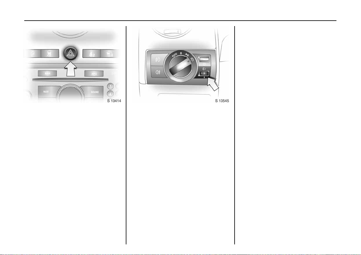
Picture no: s0013414.tif
Hazard warning lights
To switch on, press button ¨.
To switch off, press button ¨ again.
To aid location of the pushbutton, the red
surface is illuminated whe n the ignition is
switched on. When the button is pressed,
its control indicator flashes in unison with
the haz ard warning lights.
Picture no: s0013545.tif
Headlight range adjustment q
Manual headlight range adjustment 3
With dipped beam switched on, adjust
headlight range to suit v ehicle load.
Correct adjustment of the headlight range
re du ce s d azzle for o t h er r oa d u se rs.
Automatic level control system 3 see page 139.
Vehicles wit ho ut le vel control system
z Front seats occupied = 0
z All seats occupied = 1
z All seats occupied and load in
luggage compa rtment
z Driver’s seat occupied and load
in luggage compartment
=2
=3
Lighting 93
Ve hicles with lev el c ont rol s yste m
z Front seats occupied = 0
z All se ats occupi ed = 1
z All seats occupied and load in
luggage compartment
z Driver’s seat occupie d and loa d
in luggage compartment
Automatic headlight ra nge adjustment 3
On vehicles with Xenon headlights, the
range of the headlights is adjusted
automatically based on v ehicle load.
If control indicator q for automatic
headlight range ad justment illuminates in
the instrument cluster w hile driving, a fault
has occurred.
Have the cause of the fault remedied
immediately. Consult a workshop.
=1
=2
Page 99

Ligh ting94
Picture no: s0014528.tif
Door-to-door lig hting
The dipped beam and reversing lights
illuminate for approx. 30 seconds after the
driver ex its th e veh icle a nd closes th e door.
To activate function:
1. Switch off ignition.
2. Remove ignition key.
3. Open driver’s door.
4. Pull turn signal stalk towards
steering wheel.
If th e driv er’s doo r is left open , the lights will
extinguish after two minute s.
Door-to-door lighting can be deactivated
by inserting the key in the starter switch or
by pulling the turn signal stalk towards the
stee ring whee l aga in while the driv er’s door
is open.
Picture no: s0013541.tif
In strument illumination,
information display illum ination
Comes on when ignition is switched on.
Brightness can be adjusted when the
exterior lights are on: turn wheel to the
rig ht or le ft until the desired brightness is
ob t ai ned.
If drive r’s door is opened or q is pressed on
the remote control, instrument panel lights
will illuminate automatically and sta y on
for approx. 30 seconds until starter switch
is turned to the ACC position.
Display mode 3 - see page 83.
Picture no: s0013428.tif
Interior courtesy lights
Front reading lights, rear interior lights and
luggage compa rtment lights function as
courtesy lighting and illuminate when the
doors or tailgate are opened.
If d oors or tailgate rema in op ened, the
lights stay illuminate d for approx.
10 minutes.
Once all doors and the tailgate are closed,
the courtesy lights dim gradually after
app rox . 10 se cond s.
By pressing button d, both front rea ding
lights and the rear interior lights illuminate.
Press th e button again to turn the lights off.
Page 100

Lighting 95
Courtesy lights can be turned off
Picture no: s0012875.tif
immediately by pressing button K.
Front r ead ing lig hts
Picture no: s0012878.tif
Left and right reading lights are
individually operable. With ignition on:
Off = Press button again
9 Warning
Avoid using interior lights while d riving in
the dark, as they can reduce driver
visibility.
Rear i nterior lights
Picture no: s0013429.tif
P r es s bu tton to tur n on l eft a nd r ig h t r ear
interior lights indiv idually.
Press button again to turn the light off.On = Press button L or M
 Loading...