

Page 1

Owner’s Manual
Model Yea r 2009.5
Edition: January 2009
TS 1664-B-09
VAUXHALL Antara
Operation, Safety, Maintenance
Page 2

-2
Data specific to your vehicle
Pleas e en ter your veh icle ’s da ta h e re to ke ep it ea sily acces s ibl e.
This information is available un der the section "Technical da ta" as well as on the identification plate .
Fuel
Designation
Engine oil
Grade
Viscosity
Tyre pressure
Ty re si ze for loa d of up to 4 persons for full load
Summe r tyres Front Rear Front Rear
Winter ty res Front Rear Front Rear
Weights
Permissible Gross Vehicle Weight
– EC kerbweight
= Pay load
Page 3

-1
Your Antara
is an intelligent combin ation of forwardlooking technology, impressive safety,
environmental friendliness and e conomy .
It now lies with you to drive your vehicle
safely and ensure that it performs
perfectly. This Owner's Manual provide s
you with all the necessary information to
that end.
Ma ke sure your passeng ers are aware of
th e po ss i b l e r i sk of ac c iden t a nd inj u ry
which ma y result from improper use of the
vehicle.
You must always comply with the spec ific
law s of the country that you are travelling
th r o u gh. T h es e la w s m ay di ffe r fr om the
information in this Owner’s Manu al.
W h en instr u cted to seek t h e as sis tan ce of a
w ork s ho p, w e rec om men d t h at you co n sul t
a Vauxhall Authorised Repairer.
All Vauxhall Authorised Repa irers offe r
first-c lass service at re asonable price s.
Expe rienced me chanics, traine d by
Vauxhall, w ork according to specific
Vauxhall ins tructions.
The Owner's Manual should always be kep t
together with the Service and Warranty
Booklet in the vehicle: Ready to hand in the
glov e comp artment.
Make use of the Owner's Manual:
z Its "In brief" section will give you an initial
overview.
z The table of contents at the beginning of
the Owner’s Manual and within the
individ ual chapters will show you where
everything is.
z Its index will help you find what y ou
want.
z It will familiarise y ou w ith the
sophisticated te chnology.
z It will increase you r pleasure in your
vehicle.
z It will help you to handle your vehicle
expertly.
The Owner’s Ma nual is de signed to be
clearly laid-out and easily understood.
This symbol signifies:
6 Continue reading on next page .
3 The asterisk signifies eq uipment not
fitted to all vehicles (model variants,
engine options, models specific to one
country, optional equipment, Vauxhall
genuine parts and accessories).
9 Warning
Text marked 9 Warning provides
inform ation on risk of accident or injury.
Disregard of the instructions may lead to
injuries or endanger life.
Inform your passengers acc ordingly.
Yellow arrows in the illustrations serve as
points of reference or indicate some action
to be p erformed.
Bla ck arrows in the illustrations indicate a
reaction or a second a ction to be
performed.
Directional data, e.g. left or right, or front
or back, in the descriptions always relates
to the di rec ti o n o f tr a v el .
Thank you for choosing a V auxhall.
We wish you many hours of pleasurable
driv ing
Your Vauxhall Team
Page 4

0
Page 5

1
Contents
Commitment to customer
satisfaction
Our ai m: to k eep you happy with your
vehicle. All Vauxhall Authorised Repairers
offer first-class service a t competitive
prices. Experienced, factory-trained
technicians work according to factory
instructions. Your Authorised Repairer can
supply yo u with GEN UINE V AU XHALL -
APPROVED PARTS, which have undergone
stringent quality and precision chec ks, and
of course useful and a ttractive
VAUXHALL-APPROVED ACCESSORIES.
Our name is your guarantee!
For d eta ils of the
Vauxhall Authoris ed Rep airer Ne tw ork,
please ring this number; 0845 090 2044
In b rie f .. ......... ......... ......... ......... ......... ........ ..2
Locks , do o rs, win dows ... .... ......... ......... ... 1 7
S eats, in terio r ..... ........ ......... ......... ......... ... 3 2
Instrum ents, con trols . ......... ......... ......... ... 6 6
Ligh ting ..... ......... ........ ..... ......... .... ......... ... 90
Info tain ment sys tem .. ..... .... ......... ......... ... 9 8
C lim ate c ontrol .. ........ ......... ......... ......... . 10 0
Driving an d op eration ... .... ......... ......... . 11 2
S elf-h elp, vehicle care .... ......... .... ......... . 168
S ervice , mainte na nce ..... ......... ......... ..... 202
Te chnical data .. ........ ..... ......... .... ..... ..... 210
Inde x . ......... ......... ........ ......... ......... ......... . 224
Page 6
In b rie f2
In brief
To unlock and open the vehicle:
Press button q , pull door handle
6 Door locks - see pages 26, 68 ,
keys - see page 17,
electronic im mobiliser - see page 18,
radio frequency rem ote control -
see page 19,
central locking s ystem - s ee page 21,
anti-theft locking system - see pag e 23,
Vauxhall alarm system - see page 23.
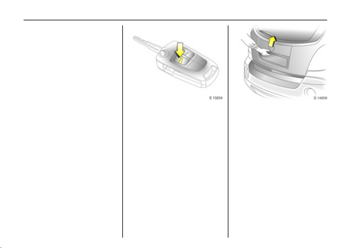
To unlock an d open the tailgate:
Press button q on remote c ontrol,
operate button above
number plate
6 Tailgate - see page 22,
radio frequency remote control -
see page 1 9,
ce ntral loc king sy ste m - see p a ge 2 1 ,
Vauxhall alarm system - see page 23.
Page 7
In brief 3
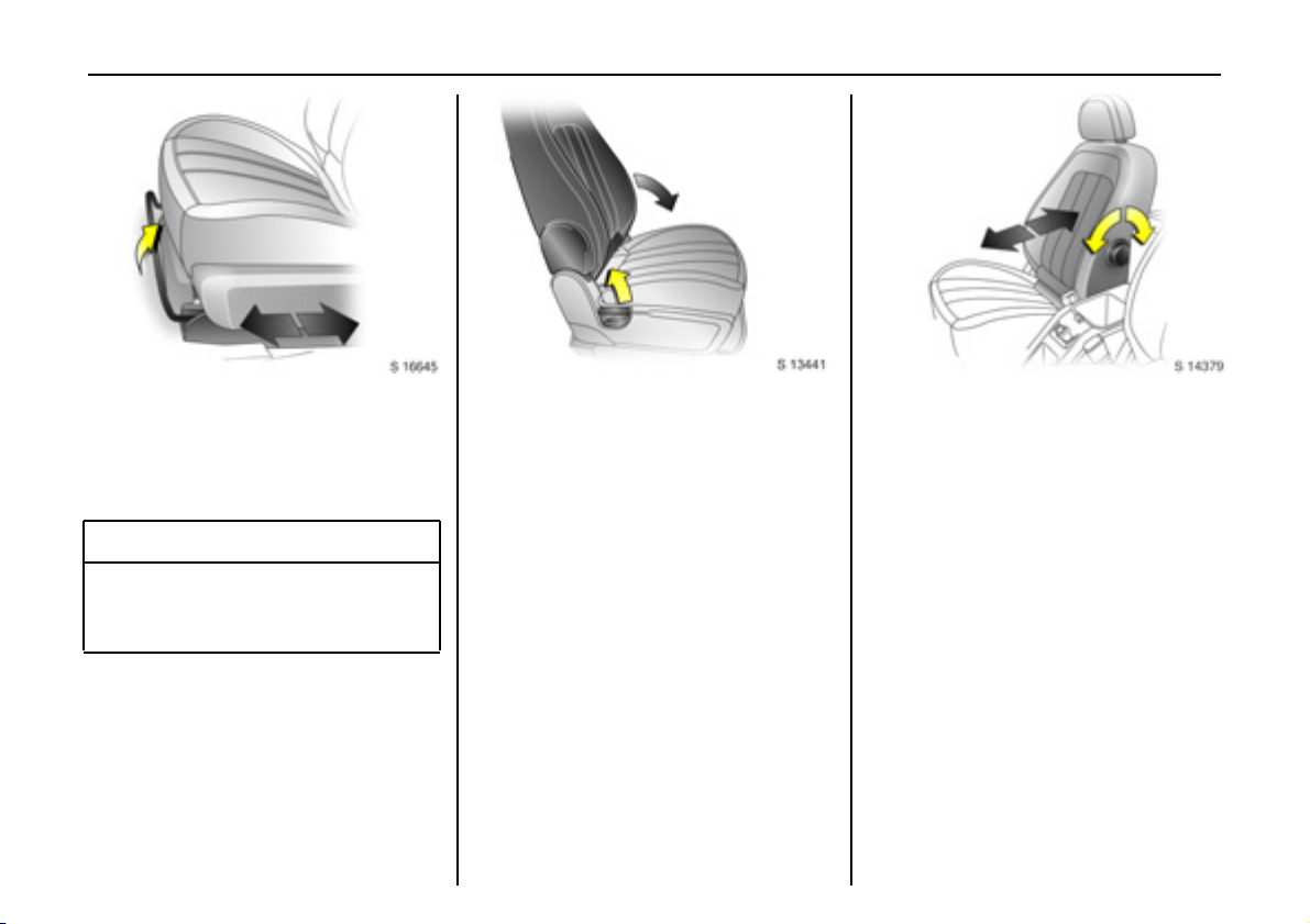
Front seat adjustment:
Pull handle, slide seat,
release handle
6 Seats - se e pa ge 32,
seat p osition - see page 3 4.
9 Wa rning
Important: Do not sit nearer than
10 in ches (25 cm ) f r om the s teering
wheel, to permit safe airbag deployment.
Adjusting front seat backrests:
Lift release lever on outboard side
of seat
Move seat backrest to suit seating position.
Do not lean on seat backrest whilst
adjusting it.
6 Seats - see page 32,
seat position - se e pa ge 34.
A djus ting the lu m ba r su pp or t 3:
Turn handwheel
Adjust lumbar sup port to suit personal
requirements.
Page 8
In b rie f4
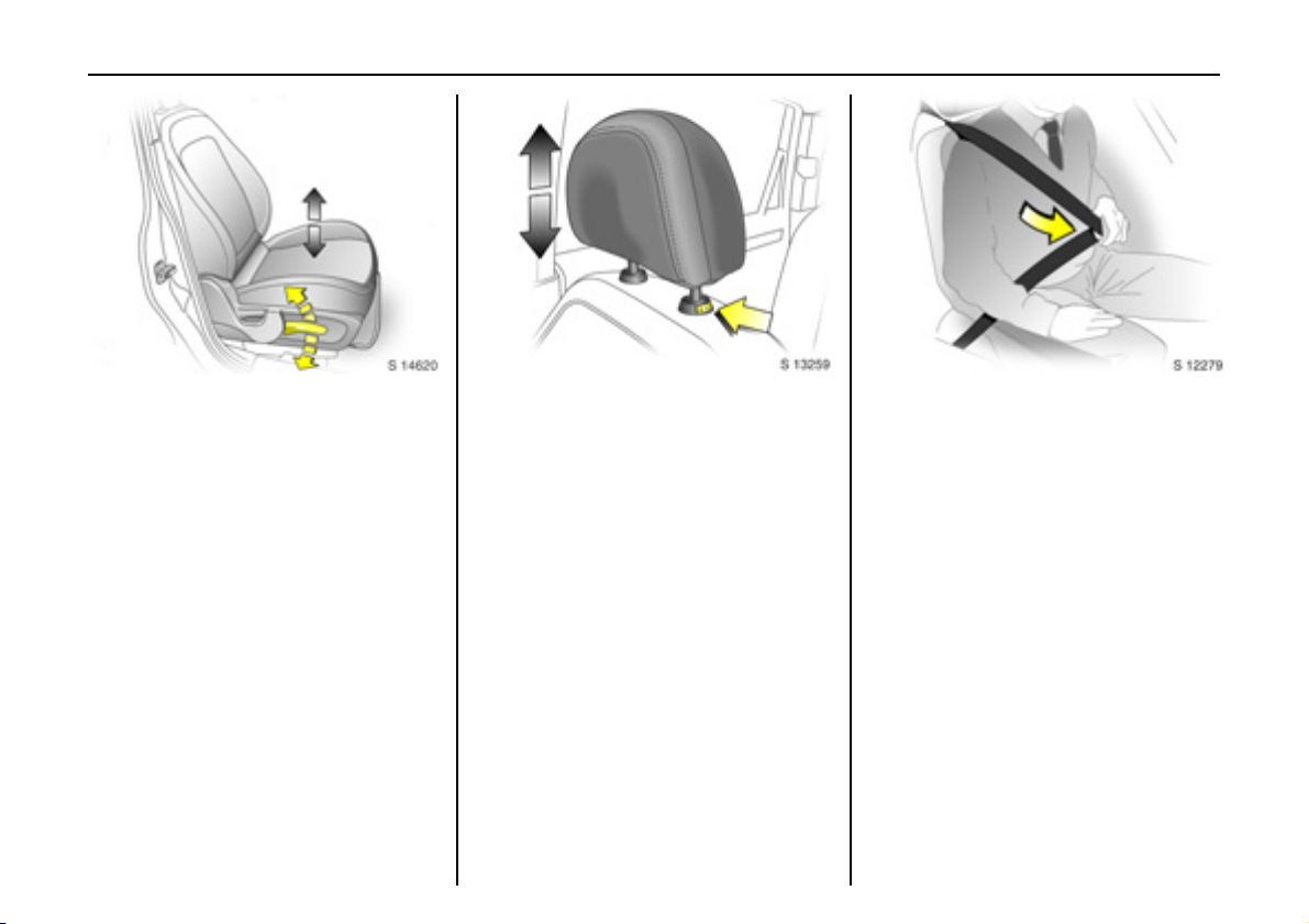
Adjusting seat height 3:
Raise or lower lever on outboard
side of seat
Lever pumping ac tion
upward: raises seat
downward: lowers seat
6 Seats - se e pa ge 32,
seat p osition – see page 34.
Adjusting head restraint height:
Press release button,
adjust height, then release
6 Head restraints - see page 35,
he ad re straint pos ition – see page 35.
Fitting seat belt:
Draw seat belt smoothly from
inertia reel, guide over shoulder
and enga ge in buck le
The belt must not be twisted at any point.
The lap be lt must lie snugly against the
body .
The backre sts must not be tilted back too
far (rec ommende d ma ximum tilting angle
app rox. 25°).
To re lease b elt, press red button on belt
buckle.
6 Seat belts – see p ages 39 to 43,
airbag systems – see pag e 48 ,
seat position – see pag e 34 .
Page 9
In brief 5
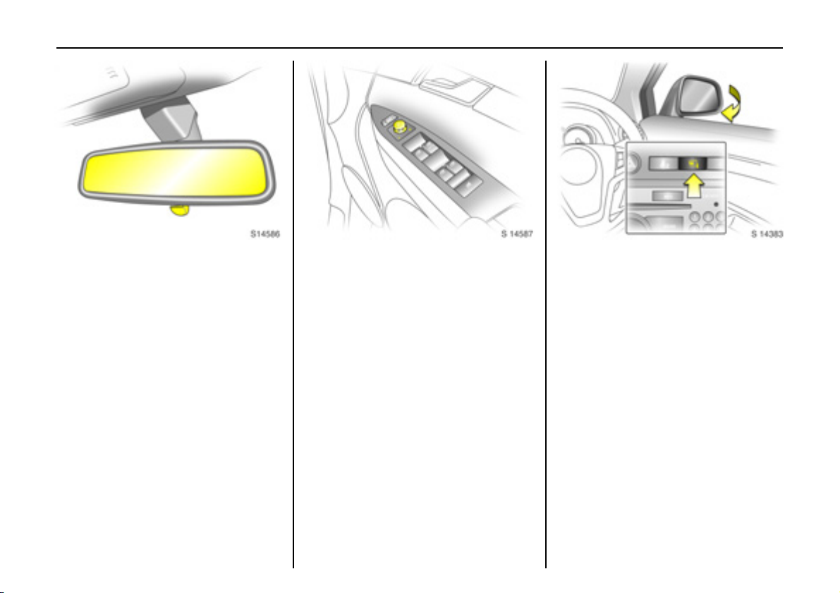
To adjust interior mirror:
Swivel mirror housing
Swivel lever on underside of mirror housing
to red uce daz zle a t nig ht.
Take care when driving with interior mirror
adjusted for night vision. Rear view may be
slig htly distorted in this position.
6 Mirrors - see page 27,
automatic anti-dazzle interior mirror see page 2 8.
Electrically adjustable exterior
mirrors:
Four way switch in driver’s door
Mo ve se lector s witch to L o r R; f our w ay
swi t c h a d jus ts c o rre sp onding m irror.
6 Further information,
autom atic anti-dazzle exterior mirrors -
see page 27,
heated exterior mirrors - se e page 102.
Fold in exterior mirrors:
Manually: press lightly.
Electrically 3: with starter switch in
positions ACC or ON, press button n and
both mirrors will fold in.
Press button n a g ain; bo th mirro rs will fold
to the driving position.
If a fold ed-in e lect ric mir ror has b e en
folded out manually, pressing button n
only folds the other mirror out. Pressing
button n a gain folds both m irrors back in.
Fold mirrors b ack into driving position
before driving the ve hicle.
Page 10
6In brief
Page 11

In brief 7
Page
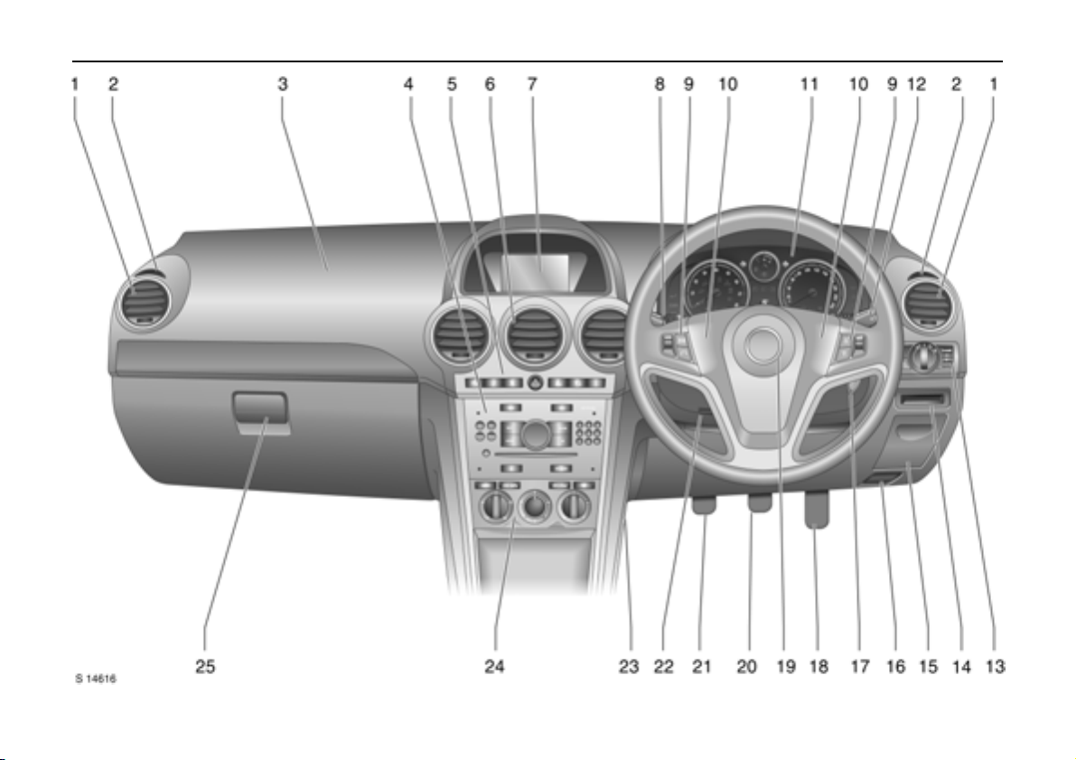
1 Side air v ents .... ..... ......... ........ ......... 10 1
2 Doo r window de froster v ents ..... .... 10 1
3 Front pa ssenge r’s airbag ...... ......... ..4 8
4 Infotainm ent s ys t em ...... ........ ......... ..9 8
5 Haza rd warnin g ........ ..... ........ ......... ..1 0
Parking dis tance sensors 3 ........ .... 139
Des ce nt Con trol Sys tem (DC S) ... .... 135
Electronic Stability Control
(ES C) . .... ......... ......... ......... ........ ......... 13 3
Front pa ssenge r’s
seat belt reminder 3 . ......... ......... ...... 42
Fold in exterior mirrors 3 ....... ......... ..2 6
Control indicator for
Vauxhall alarm system 3 ...... ..... .... ..2 5
6 Cen tre air v ents ..... .... ......... ......... .... 10 1
7 Central information dis play for tim e,
date, outside temperature,
Infotainm ent system,
check control 3 ......... ..... ........ ......... ..8 7
Trip computer 3 .... ......... ........ ..... 77 , 8 4
8 Headlight flash and main beam .....10
turn sign al ligh ts.... .... ......... .... ......... ..10
door -t o-door lighting ......... ......... .... ..94
cruise control 3 ......... ......... ......... .... 137
Pa ge
9 Infotai n me nt sy ste m
remo te control buttons. .... ......... ..... ..9 8
Tri p c o mp u ter 3 ........ .... ......... ..... 77, 84
10 Horn .... ..... ......... ......... ........ ......... ....... 1 1
11 Instru men ts.. ..... ......... ........ ......... ....... 6 6
12 Windscreen and tailgate
wiper a nd wash.... ..... ........ ......... .1 1 , 1 2
he adlight wash 3. ..... ........ ......... ....... 1 2
13 Side lights . .... ......... ......... ......... ......... ..9 0
dipped beam ... ......... ........ ......... .1 0, 90
automatic dippe d be am
activation 3...... .... ......... ......... ......... .. 91
headlight range adjustment 3. ..... .. 93
front f og ligh ts . .... ......... ......... ......... ..9 2
fog tail light. ......... ..... ........ ..... .... ....... 9 2
instrument illumination. .... ......... ....... 94
14 Card holde r. ..... ......... ........ ......... ....... 6 3
15 Coin stor age ..... .... ......... ......... ......... .. 63
Page
16 Bonnet re lease .... ......... ......... ......... . 16 8
17 S ta rter s w itch .. .... ......... ......... ......... ......9
18 Acce lerator pe dal ........ ......... ......... . 12 4
19 Drive r’s airbag ......... .... ......... ..... ....... 4 8
20 Brake pedal ..... ......... ......... ......1 24, 143
21 Clutch pedal 3 ......... ......... ...... 12 4, 125
22 S teerin g w heel a djustment .. ..... ........ ..9
23 Fusebox .. ......... ......... ......... ......... ..... 179
24 C lim ate c ontrol ... ..... ......... ......... ..... 100
25 Glove co mpartme nt .... ......... .... 60, 102
Page 12

In b rie f8
Control indicators
ABS ( Anti-lock Brak e S ystem):
u
se e p age 14 5.
Trailer indic ator 3:
g
see page 66.
Brake system:
4
see pages 66, 142.
Parking distance sensors 3:
r
see pages 67, 139.
DCS (Descent Control System):
5
see pages 67, 135.
AWD ( All Whee l D rive ) 3:
B
see pages 67, 118.
ESC Activ e & Wa rning
7
(Electronic S tability C ontrol):
see page 133.
ESC Not Re ad y:
A
see page 133.
ESC OFF:
J
see page 133.
Automatic headlight range
q
adjustment 3:
see pages 67, 94.
Coolant t em perature:
W
see pages 67, 192.
Electron ic im mobil iser:
o
see page s 18, 68.
Door open:
9
see page 6 8.
Engine electronics,
3
tr a n sm is si on e le c t r oni cs 3:
see page s 68, 131.
Airbag systems 3,
v
belt tensione rs :
see page s 40, 48.
Tailgate open:
1
see page 6 8.
Driv er’ s seat b el t reminder:
X
see page 6 8.
Turn signal lights:
O
see page s 10, 68, 91.
Lo w fuel level:
Y
see pages 68, 72, 129, 220.
Front fog li ghts:
>
see page s 69, 92.
Fog tai l light :
r
see page s 69, 92.
Headlight ma in beam:
P
see page s 10, 69, 91.
Low windscreen wash fluid:
G
see page 6 9.
Water in diesel fuel filter 3:
N
see pages 6 9, 191.
Change engine oil 3 :
C
see page 69.
Pr ehe a tin g for die s el engi nes 3:
N
see pages 1 5, 69.
DPF (D iese l pa rticle filt er ) 3 :
I
see page s 69, 132.
Cruise control 3:
m
see page 137.
Engine oil lev el 3:
S
see page 69.
Powe r steering:
2
see page 69.
Anti-the ft ala rm system ac tivation
a
without mo nitorin g of pas senger
compa rtmen t and ve hicle tilt 3:
see page 24.
Engine oil pressure :
I
see page 70.
Alternator:
p
see page 70.
Exhaust emissions:
Z
see pages 7 0, 131.
Wi n ter pro gra m me :
0
see pages 7 0, 114.
Page 13
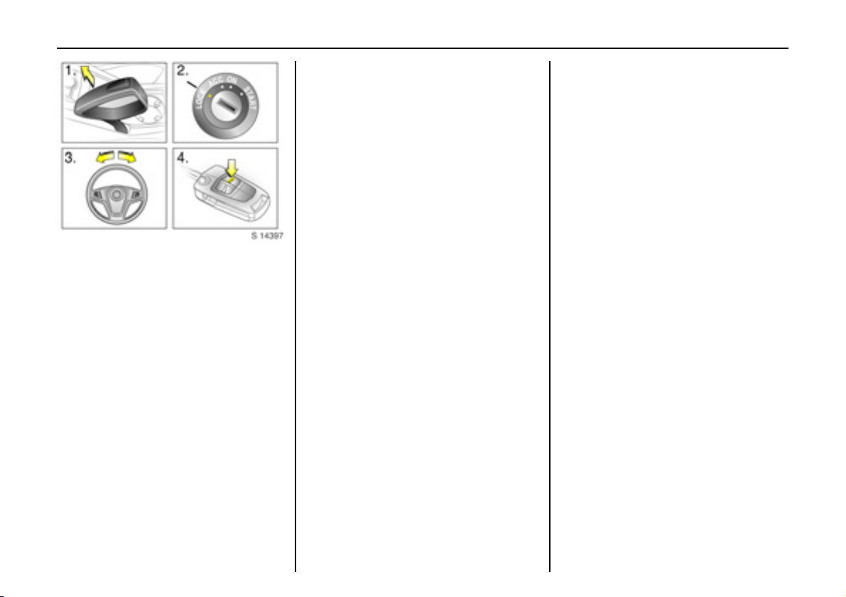
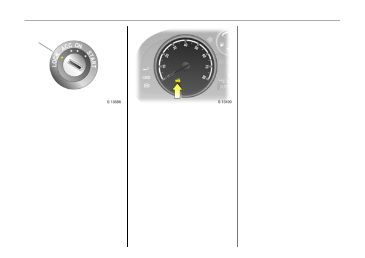
In brief 9
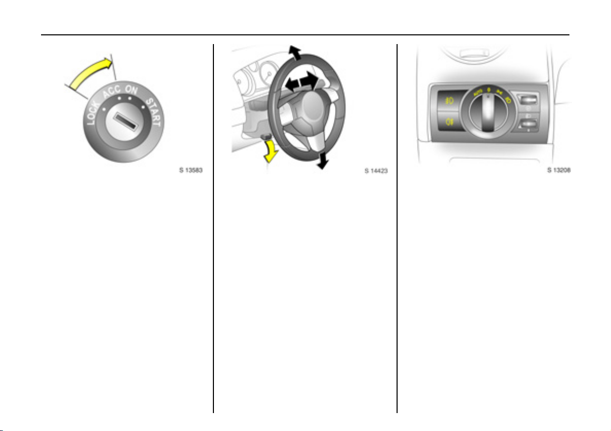
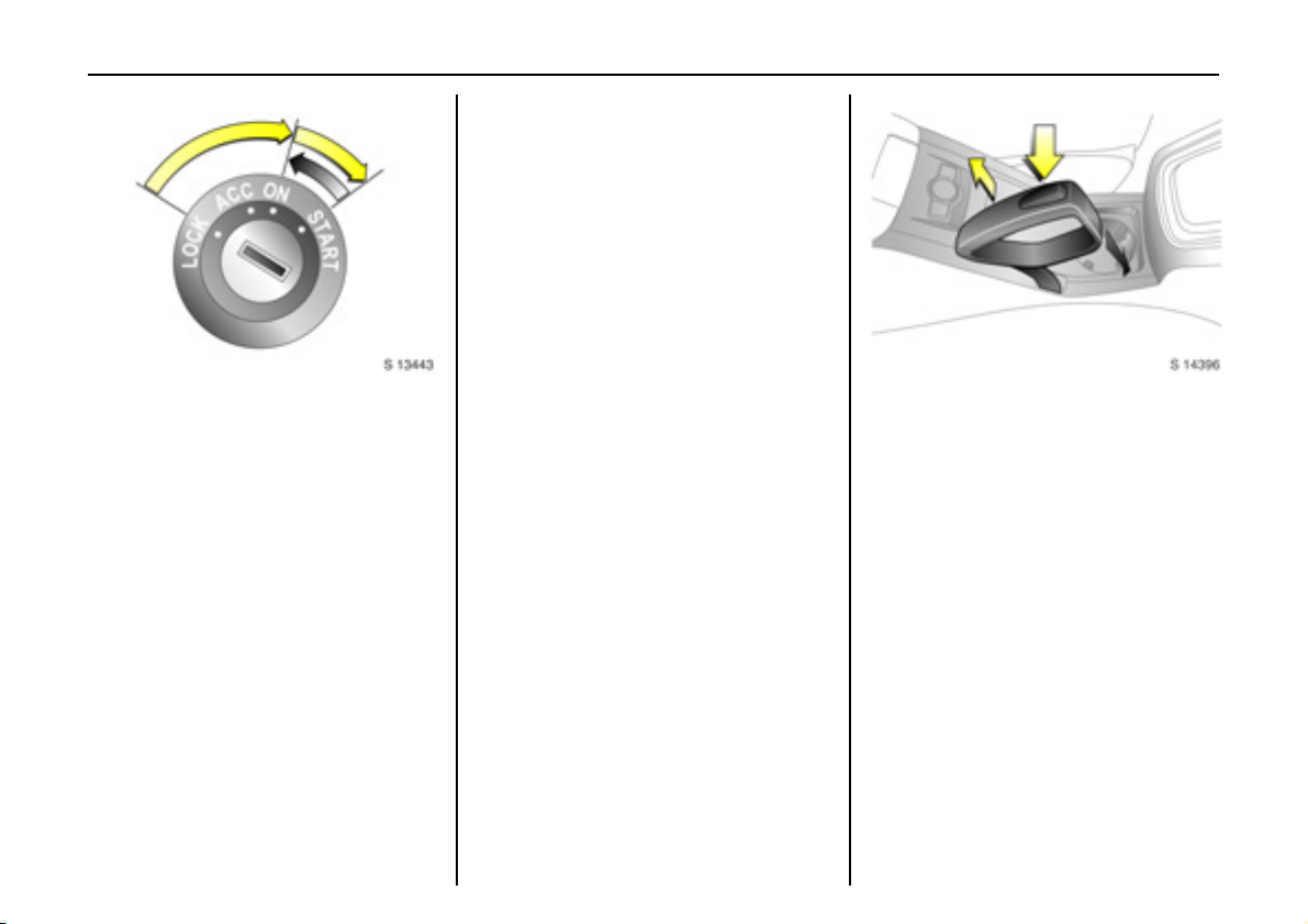
St e er ing col u m n lock and ig nit i on:
Turn key to position ACC.
To release lock,
rotate steering wheel slightly
Po sition s:
LOCK = Ignition off
ACC = Steering unlocked, ignition off
O N = Ign ition o n, with di es el en gin e:
preheating
STA RT = Start (transm ission in neu tral)
6 Starting - see page 15,
electronic immobiliser - see page 18,
parking the vehicle - see page 16.
Steering wheel adjustment:
Mo velever down,
adjust height and distance,
move lever up and engage
Adjust steering wheel only with vehicle
stationary and steering column lock
re l ea s e d.
Push the lever firmly upwards to ensure
that the steering wheel is locked in pos ition.
6 Airbag systems - see page 48.
Exterior lighting:
Turn li gh t s w itc h :
J =Off
8 = Sidelights
9 = Dipped bea m or
main beam
AUTO = Automatic dipp ed
beam activation 3
Press button:
> =Front fog lights
r = Fog tail light
6 Headlig ht warning device - see pag e 88 ,
further information - se e page 90,
h ea d l i g ht r ang e ad jus t m ent 3 -
see page 93,
headlights whe n driving abroad -
see page 97,
daytime running lights 3 - see page 90.
Page 14
In b rie f10
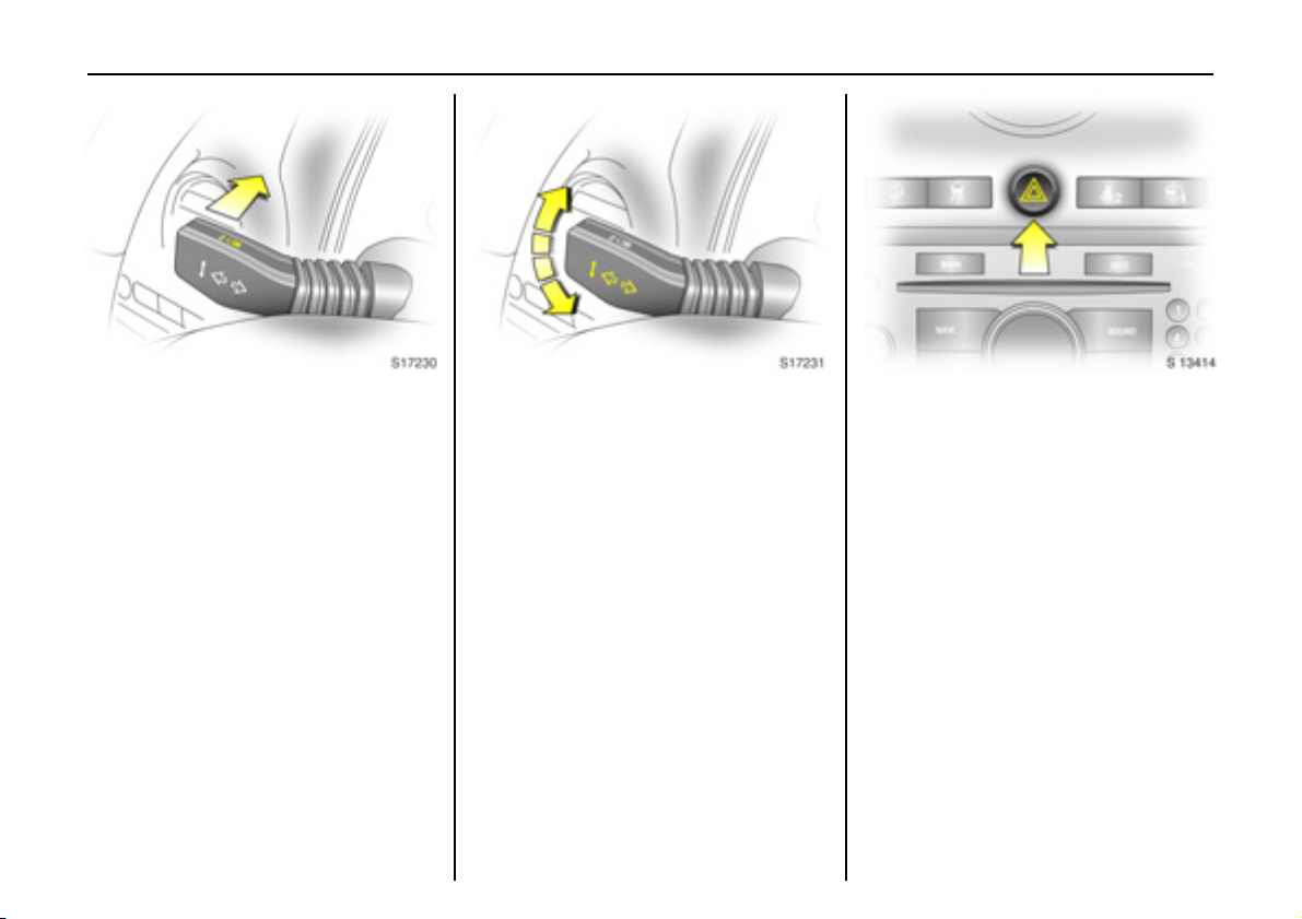
Headlight flash, main and dipped
bea m:
Headlight
flash
=Pull stalk
towards
steering wheel
Main beam = Push stal k
forwards
Dipped beam = Pull sta lk bac k
towards
steering wheel
6 Main beam, headlight fla sh see page 9 1.
Turn signal lights:
Stalk in rest position
Upwards = Right turn
Downwards = Left turn
6 Turn signal lights - see page 9 1.
Hazard warning lights:
On = Press ¨
Off = Press ¨ again
6 Hazard warning lig hts - see pag e 93.
Page 15
In brief 11
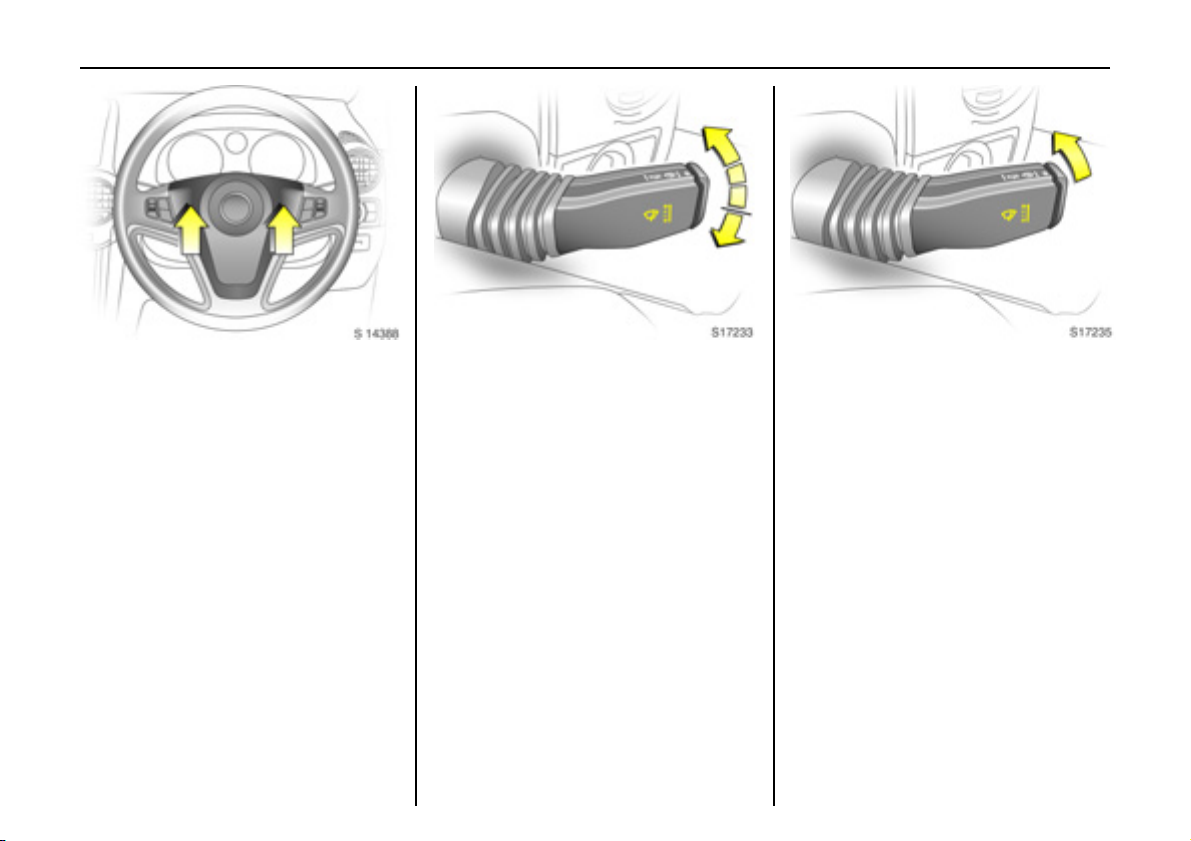
Activate horn j:
Press either side of the
steering wheel
The horn will sound regardless of starter
switch position.
6 Airbag systems - see page 4 8,
remote control on steering whe el -
see page 9 8.
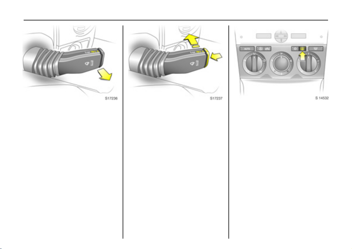
Windscreen wiper:
Mo ve s talk upwards
J =Off
$ =Timed interval wipe
% =Slow
& =Fast
Press stalk down from position J:
Single swipe.
6 Windscreen wipe r - see pag e 88,
adjustable wipe r interval - see p age 88,
further information - see pages 195, 199,
201.
Automatic wiping with rain
sensor 3:
Move stalk to automatic wiping
with rain sensor position $
The ra in sensor detects the amount of
water on the win dsc reen and auto matically
regulates the windscreen wiper.
6 Windscreen wipe r - see page 88,
further information - se e pages 195, 199,
201.
Page 16
In b rie f12
Operating windscreen and
headlight wash systems 3:
Pull stalk towards steering wheel
6 Windscreen and headlight wash systems
- see page 89,
further information - see pages 196, 199,
201.
Tailgate wiper and wash systems:
Wiper on = Push stalk forward
Wiper off = Pull stalk back
towards steering
wheel
Wash = Press and ho ld
button
6 Tailgate wipe r and wash systems see page 89,
further information - see pages 195, 196,
199, 201.
Heated rear window,
heated exterior mirrors 3:
Press Ü =On
Press Ü a gain = Off
6 Air conditioning - s ee page 106,
hea ted rear window, heated exterior
mirrors - see page 102.
Page 17
In brief 13
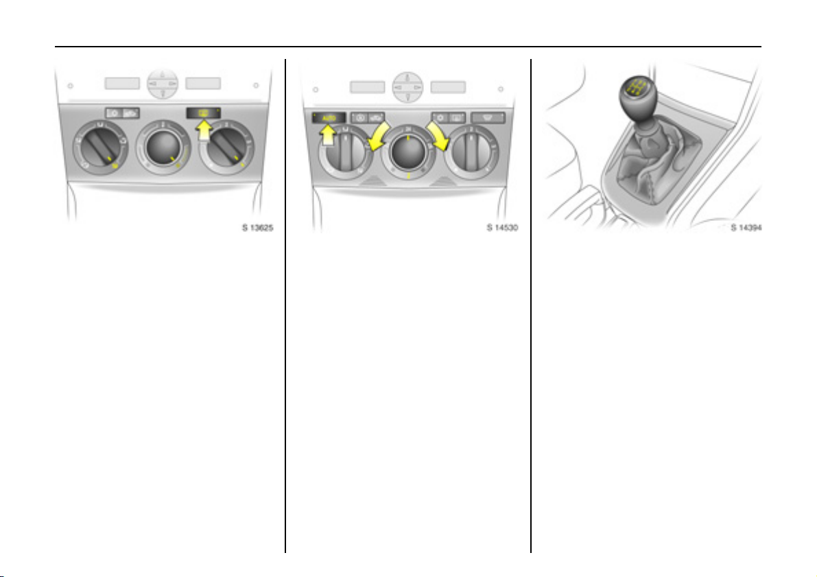
Drying misted up or iced up
windows:
Set air distribution to position l,
set the temperature rotary knob
to red and fan to position 4,
switch on heated rear windo w Ü
Close centre air vents, open side air vents
and direct the m towards th e door win dows.
6 Heating, ventilation a nd air conditioning
system - see pages 103, 106 .
To set a utomatic mode of
Electronic Climate Control 3:
Press AUTO button,
set temperature using
ro tar y kno b
Open all air ve nts.
6 Electronic Climate Control (ECC) -
see page 108.
Man ual tra nsmis sion:
1 to 5 = 1st to 5th g ear
R = Reverse gear
On ly en gage re verse ge ar wh en t he ve hicle
is sta tionary.
Page 18
In b rie f14
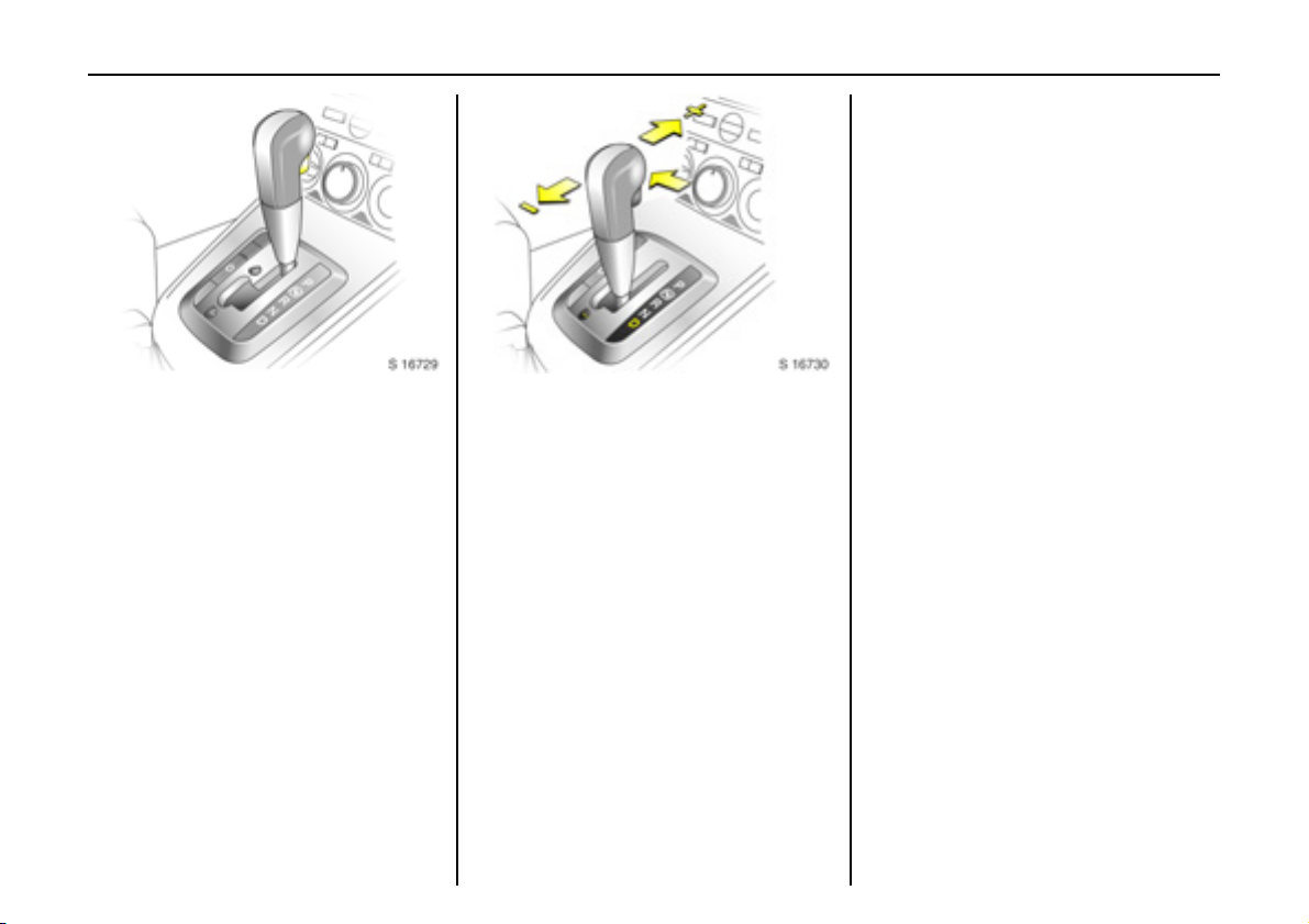
Automatic transmission 3:
P=Park position
R=Reverse
N=Neutral (idle)
D = Automatic gear selection
Starting is only possible in P or N. To move
from P or N, switc h on ignition, de press
footbrake and press selector lever button.
Engage P or R: press selector lever button.
P: Only with vehicle stationary,
first apply handbrake
R: Only with vehicle stationary.
6 Automatic transmis sion - see page 11 2 .
Manual mode:
<
= Shift to higher gear
] = Shi ft to lower gear
6 Further information - see pag e 11 4.
Before starting-off, check:
z Tyre pressures and condition.
z Engine oil level and fluid le vels in engine
compartme nt (see page 189).
z All windows, mirrors, exterior lighting
and nu mber plates are free from dirt,
snow and ice a nd are operational.
z Objects are securely located and will not
be thrown forward in the event of
sudden braking.
z Seats, seat belts and mirrors are
correctly a djusted .
z All gauges and c ontrol indicators.
z Br ake o peratio n .
Page 19
Starting the engine:
Manual transmission in neutral,
Depress clutch and footbrake,
Automatic transmission in P or N,
Do not acc elerate
Petrol engines:
Turn key to START and release it
Diesel engines:
Turn key to ON, when preheating
control indicator N
extinguishes1), turn key to START
an d releas e it
Key returns automatically to ON position
wh en r e leas ed .
Start attem pts should not last longer than
15 seconds. If engine does not start, w ait
10 seconds before repeating starting
proc edur e.
The increased engine speed automatically
returns to normal idling speed as the
engine tempe rature rises.
Driv e at a moderate speed, espe cially in
cold weather, until normal engine
op erat ing t e mperat u res h ave been
re a ch e d .
6 Electronic immobilis er - se e pa ge 18,
diesel fuel system - see page 168,
further information - see pages 124, 126,
128.
In brief 15
Releasing the handbrake:
Raise lever slightly,
press release button,
lower lever fully
To re duce operating forc es, depress
footbrake at the same time .
Do not drive with handbrake on, to avoid
dam age to brakes on the rear w heels. Do
not apply handbrake while vehicle is in
motion or as a substitute for the footbrake.
Drive carefully, economically and with the
environment in mind. While driving, do not
do a nything that c ould distract y ou.
6 Handbrake - s ee page 144.
1)
Preh eating system switches on o nly if o utside
temperature is low.
Page 20
In b rie f16
Parking the vehicle:
Apply handbrak e firml y,
close windows,
switch off engine, remove key,
engage steering column lock,
lock v ehicle
6 Further information - see pages 18, 125,
radio frequency remote control -
see page 1 9,
central locking system - s ee pag e 21 ,
Vauxhall alarm system - see page 23.
Advice when parkin g:
z Always ap ply handbrake firmly and as
firmly as possible on slopes.
z Push key into starter switch before
removing (vehicles with autom atic
transmission 3: depress footb ra ke and
shift into P before removing key). Turn
steering wheel until lock is felt to e ngage
(anti-theft protection).
z If the vehicle is parked on a level surface
or an uphill slope , select 1st g ear before
switching ignition off (vehicles with
automatic transmission 3: mo ve sele ctor
lever to P). Also turn front wheels away
from ke rb if parked on an uphill s lope.
If the vehicle is parke d on a downhill
slope, select reverse gear before
switching ignition off (vehicles with
automatic transmission 3: mo ve sele ctor
lever to P). Also turn front wheels
towards kerb.
z Sw itch off exte rior lights, otherwise the
headlight warning device will sound
when the driver’s door is opened.
z C ooling fans may run on afte r the engine
has been switched off.
z Do not park on easily ignitable surfaces
as hot exhaust system temperatures
could cause the surface to ignite.
That was a brief overview of the
mos t imp ortant in form a tion f or
your first drive in your Antara.
Your vehicle has still more
instruments and controls,
possibly also optional equipment.
The rem a in ing ch apte rs of the
Owner’s Manual contain
important information on
operation, safety and
maintenance as well as a
com plete index.
Page 21
Locks, doors, windows 17
Locks, doors, windows
Re placem ent keys ... ..... ......... ........ ..... 17
Lock cylin de rs ...... ......... ......... ........ ..... 17
Ca r Pass... ........ ..... ......... ......... .... ......... 17
Key with foldaw ay key section 3. ..... 17
Electronic immobiliser....... ......... ......... 18
Radio fre quency re mote control .. ..... 19
C e n tral lo ckin g system ..... ......... ......... 21
Tailgate ... .... ......... .... ......... ..... ........ ..... 22
Mechanical anti-theft loc king
sy ste m 3 ... ......... .... ......... ..... ........ ..... 23
Vauxhall alarm system 3. ..... .... ......... 23
Child safe ty locks . .... ......... ......... ......... 26
Ex terior mirr ors..... .... ......... ......... ......... 26
Interior mirror ....... ......... ......... ........ ..... 27
Ele ct ric win do ws... .... ......... ......... ......... 28
Sun visors.. .... ......... .... ......... ......... .... ..... 30
Slide / tilt sunroof 3 ...... ......... .... ......... 30
Replacement keys
The key is a c onstituent of the electronic
immobiliser. In c ase of loss, replacement
keys can be ordered from your Vauxhall
Authorised Repairer by quoting the k ey
nu m b er a n d Ve hic le Ide nt ificat i o n N u m b er
(V IN ) .
Once a new transmitter is coded, the lost
tra nsmitter will not unlock your vehicle.
Or d e ring key s fr o m a Va ux ha l l A ut h orise d
Repairer guarantees problem-free
op eration of the electronic immobiliser.
Keep spare key in a safe place.
Locks - see page 201.
Lock cylinders
Des igne d to f re e- whe el if t h ey are
forcefully rotated without the correct key or
if the correct key is not fully ins erted.
To reset, turn cylinder with the correct key
until its slot is vertical, remove key and the n
re-insert it. If the cylinder still free-wheels,
turn the key through 1 80o and re pea t
op er at io n .
Car P ass
The Car Pass contains all of the vehicle’s
data and s hould theref o r e not be k ept in
the vehicle.
Have your Car Pass to hand when
co nsu l t ing a Va ux ha ll Au th orise d Rep a i r er.
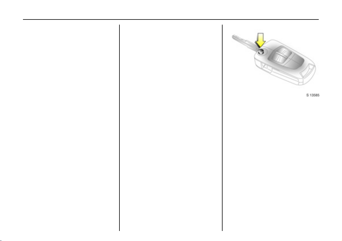
Key with foldaway key section 3
Press button to extend. Press button to
retrac t; key section au dibly engages.
Page 22
Locks, doors, wind ows18
Not e
The immobiliser doe s not lock the doors.
Therefore, after leaving the vehicle, always
lock it and switch on the Vauxhall alarm
system 3 - see pag es 21, 23.
Electronic immobiliser
The system checks whether the vehicle may
be sta rted using the key that has been
in se r ted. If t h e k ey is re c o gnise d as
"authorised", the vehicle can be started.
The c heck is carried out via a transponder
housed in the key.
The electronic immobiliser is automatically
activated when the key is turned to LOCK
position and re move d from the starter
switch.
Control i ndicator o for i mmobi liser
The control indicator illuminate s when the
ignition is switched on, the n extinguishes.
If the control indicator stays illuminated
after the ignition is switched on, there is a
fa ult in the immobiliser system.
z Turn key to LOCK position and remove,
z wait a pproximately two s econds ,
z then repeat starting proce dure.
If the control indicator fails to extinguish,
try to s tart the engine using the s pare key
and seek the a ssistance of a workshop.
Page 23
Locks, doors, windows 19
Radio frequency remote control
The remote control is used to operate:
z Central locking system ,
z Mechanical anti-theft locking system 3,
z Vauxhall alarm system 3.
The remote control has a range of approx.
6 me tres. The range may be reduce d due
to environmental cond itions or shadowing
and reflection of the radio waves.
To opera te the remote control, direct the
remote control unit at the vehicle.
Treat the remote control unit with care:
it should be protected aga inst moisture,
kept out of direct sunlight and should not
be operated unnecessarily.
Do not place heavy objects on the remote
control unit, and a void dropping it.
The hazard warning lig hts come on to
indicate that the remote control is
op erational.
C entra l locking s ystem
see page 2 1.
Mechanic al anti -theft locki ng system 3
see page 2 3.
Vauxhall alarm system 3
see page 2 3.
Page 24
Locks, doors, wind ows20
Fault
If the central locking system cannot be
operated with the remote c ontrol, this may
be due to the following reasons:
z The remote control is out of range .
z The battery voltage of the remote
control is too low. Change the battery in
the remote control unit.
z The remote control has been repeatedly
op erat ed outsid e the ve hicle ’s r ece ptio n
ra nge (e.g. at too great a distan ce from
the vehicle). The remote control must be
reprogrammed. We recommend you
consult your Va uxhall Authorised
Repairer.
z The system has been overloaded as a
result of re peated operation at short
inte rvals. The powe r supply is cut-off for
a brief period.
z Inte rfer en ce f rom h i gher p ow er rad io
waves from other sources.
Lock or unlock the d oors manually using
the key or central locking s witch -
see page 2 1.
Hav e ca us e o f fa ult re me died b y a
workshop.
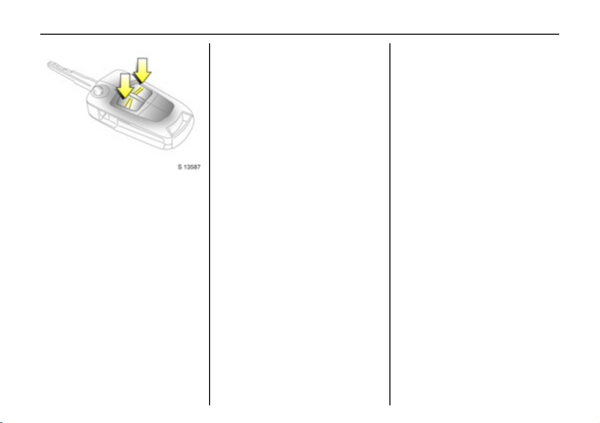
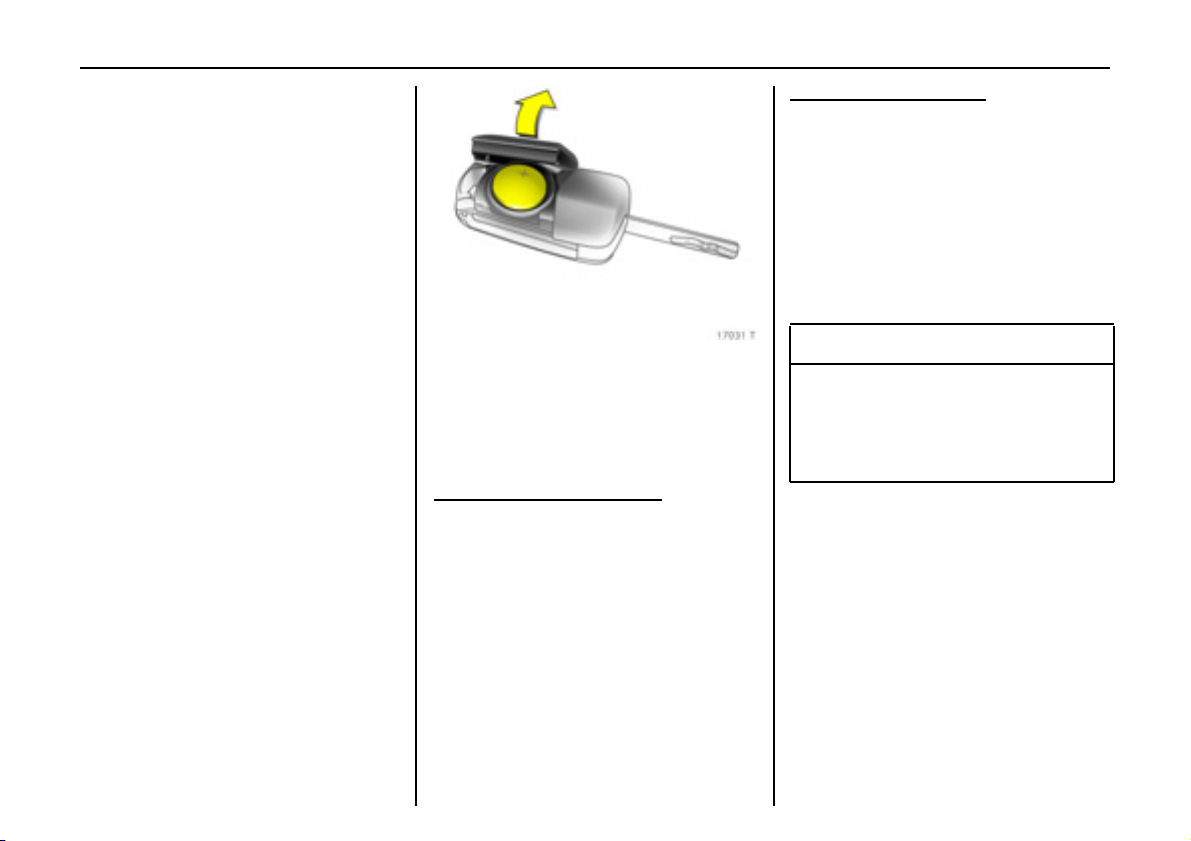
Changing battery in remote control unit
Replace the battery in accordance with the
information in chapter "Service,
maintenance" on page 202 or whe n the
ra nge of the remote control starts to
become re duced.
Key with foldaway key section:
op en co ve r b y ha nd .
Remove used battery, taking care to avoid
touching the circuit b oard to other
compon ents.
Ensure the new battery is installed correctly
with positive (+) side facing up.
Clo se cove r, en surin g it audi bly engag es in
the key part.
Key with fixed key section:
insert a small screwdriver in the notch on
the cover a nd prise it ope n.
Remove used battery, tak ing ca re to avoid
touching the circuit board to other
compon ents.
Ensure the new battery is installed correctly
with positive (+ ) side facing down towards
the base.
Close cover, ensuring it audibly engage s in
the key part.
9 Wa rnin g
Used lithium batteries can harm the
enviro n m en t. Make su re that yo u dis pos e
of old batteries in accordance with
environmental p rotection regulations.
Do not dispose with household refuse.
Page 25
Central locking system
For front doors, rear doors, tailgate and
tank flap.
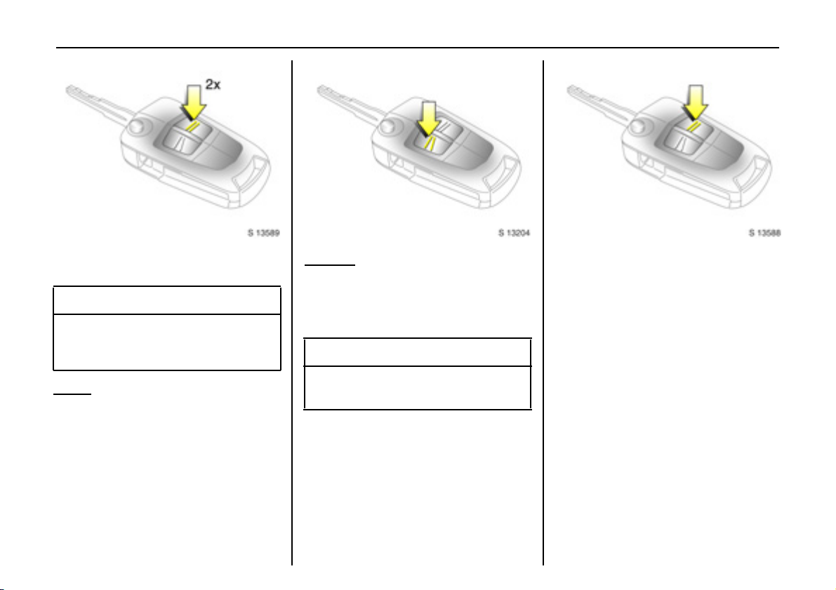
To lock:
Press button p on rem ote control
- or With the doors closed, press central locking
switch m in driver’s door.
The c entral locking system can be
activated with the windows op en.
Always ensure that the doors, bonnet,
tailgate, sunroof 3 and windows are
properly closed and that there are no
passengers left in the vehicle before
locking with the remote control.
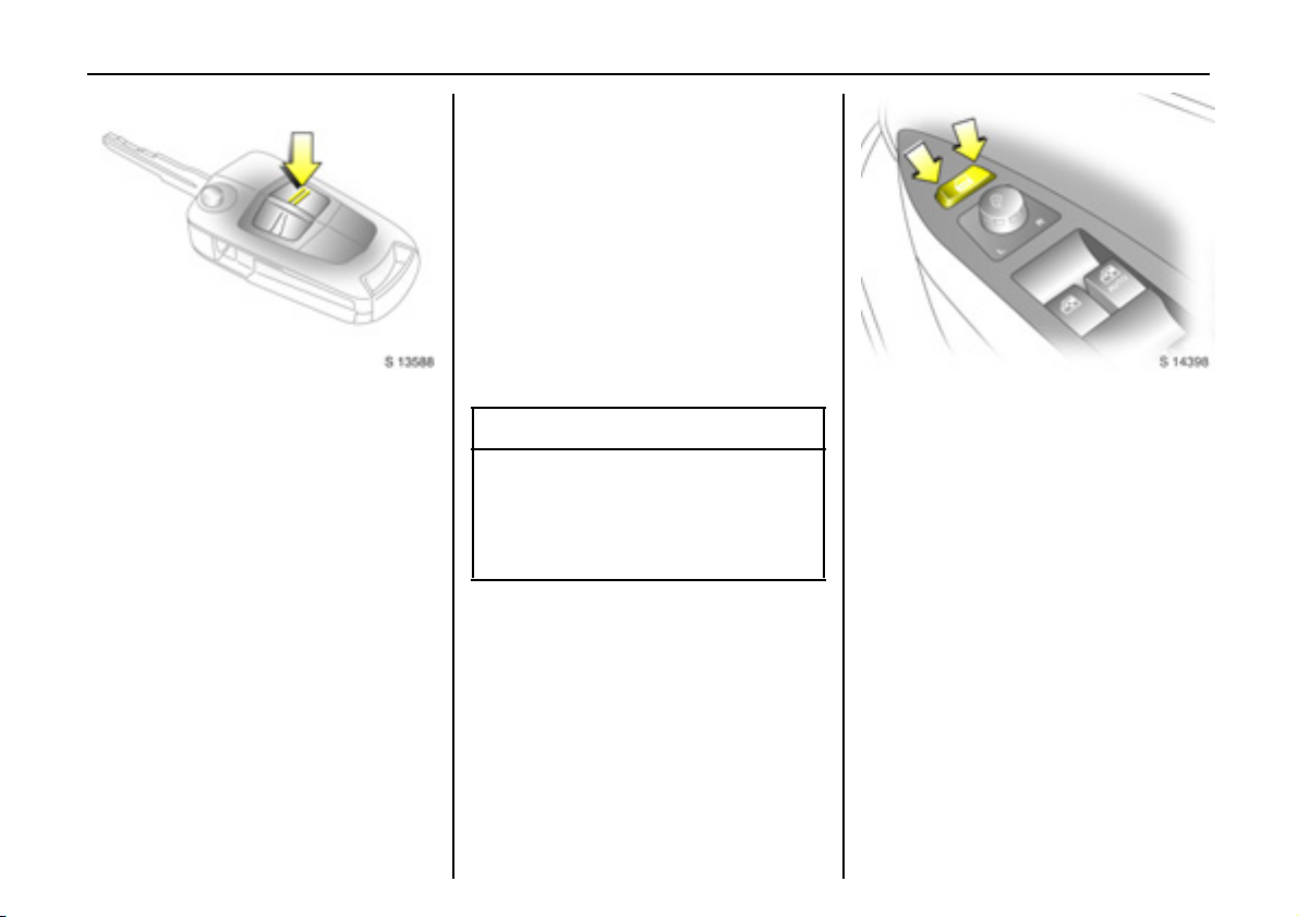
To un l oc k:
Press button q on remote control
- or Pre ss central locking switch m in driver’s
door.
If no door is opened within a pprox.
30 seconds after the vehicle has been
unlocke d via the remote control, the vehicle
is relocked automatically and Vauxhall
alarm 3 is reactivated.
Whe n bu tton q is pressed, the instrument
panel illuminates for approx. 30 seconds or
until starter switch is turne d to the
AC C position.
9 Warning
For safety reasons, the vehicle cannot be
locked or unlocked via the remote control
(and the anti-theft system 3 will not be
activated) if the key is in the starter
switch.
Locks, doors, windows 21
C entra l locking s wit ch m
Use the ce ntral locking switch to lock or
unlock the doors, tailga te and ta nk flap
from insid e the vehicle.
Press the right part of the switch to lock or
the left part of the switch to unlock.
Page 26
Locks, doors, wind ows22
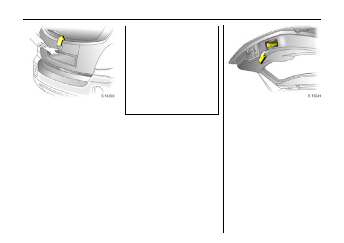
Tailgate
To unlock and open
Press button q o n remote control
- or Press central locking switch m in driv er’s
door.
The tailgate is unlock ed together with the
doors and can be opened by operating the
button above the number plate and lifting
the tailgate.
With the engine running, the tailgate will
only unlock whe n the handbrake is applied
or automatic transmission 3 is in P.
If th e tailgate is ope n when the ign ition is
switched on, ta ilg ate open control
indicator 1 illuminates in the instrument
cluster.
9 Warning
Ensure there are no obstructions and that
th er e is a deq ua te cle aran ce w he n
opening the tailgate.
Do not drive with tailgate open or ajar,
e.g. w hen transporting bulky objects,
sinc e toxic exhaust gas es cou ld
penetrate the vehicle interior.
If driving with tailgate open is necessary,
set fan to highe st speed, open all air
vents, close windows and ensure air
recirculation mode is off, to allow entry of
outside air.
To close and l ock
There is a handle on the inside of the
tailgate for closing the luggage
compa rtm ent.
Close tailgate by pus hing it down so it
latches secure ly. Ensure tailgate is fully
closed before driving.
To lock tailg ate, together with the doors:
Press button p on rem ote control
- or Press central locking switch m in driver’ s
door.
If the ignition is switched on, the tailgate
open control indicator 1 extinguishes in
the instrument cluster.
Page 27
Locks, doors, windows 23
Mechanical anti-theft locking
system 3
9 Wa rning
Do not use the system if there are people
in the vehicle. The doors cannot be
unlocked from inside.
To lock:
All doors an d the tailgate must be closed;
press button p on re mote control again
wi t h in 3 se c o nd s a fte r locki n g
- or Turn key in driver's door lock toward s rear
of vehicle aga in within 3 seconds after
locking, then turn it back to the vertical
position and re move .
Loc k buttons on all doors are positioned
such that doors cannot be opened.
To un lo ck :
Press button q on remote control
- or Turn key in driver's door lock towards front
of vehicle, then turn it back to the vertical
position and remove.
9 Warning
Unlocking is not possible in an y other
way, so ke ep spare key in a safe place.
Vauxhall alarm system 3
Th e sy ste m mon ito rs :
z Front and rear doors.
z Tailgate, bonnet.
z Starter swit ch .
z Passenger compartme nt 3.
z Vehicle tilt, e.g. if it is raised 3.
z Siren power supply 3.
Page 28
Locks, doors, wind ows24
9 Wa rning
Do not use the system if there are
passengers in the vehicle. The doors
cannot be unlocked from the inside when
the alarm is ac tivated and when the
mechanical anti-theft locking s ystem is
activated.
The remote control unit is used to operate
the anti-theft alarm system.
To activate
Always ensure that the doors, bonnet,
tailgate, sunroof 3 and windows are
properly closed and that there are no
passengers left in the vehicle before
activating a nti-theft alarm system.
Press button p on rem ote control
- or Lock driver’s door by turning key in door
lock towards rear of vehicle then turn it
back to the vertical position a nd remove;
z Hazard warning lights flash once,
z All d o ors ar e lo cked ,
z Anti-theft system is activ ated after
approx. 30 seconds.
Confirm that the control indicator starts
flash ing s lowly, afte r illuminating for
approx. 30 seconds, to s how that the antitheft system has be en activated.
If button p is pressed aga in, the anti-theft
alarm system will activate automatically,
bypassing the 30 second dela y. This will
also activ ate the mechanical anti-theft
lock ing system.
If the hazard warning lights do not flash on
activation or the control indicator fla shes
quic kly, this may indicate that a door, the
tailg ate or the bonnet is not fully closed.
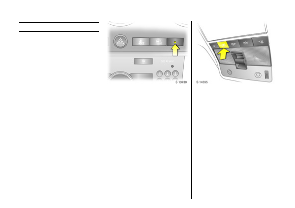
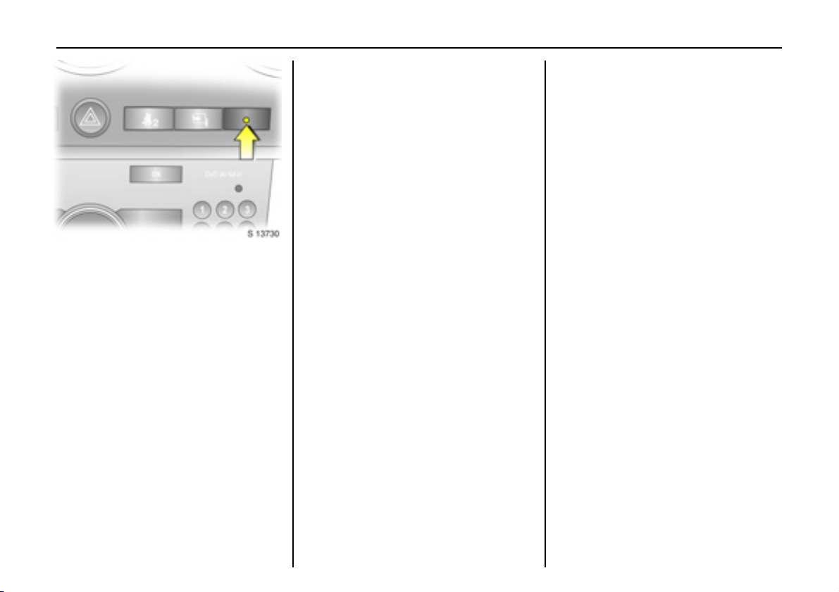
Act ivat ion without monito ring o f
passenger compartment a nd vehicle tilt 3
Switc h on when, for e xample, animals are
to be le ft in the vehicle.
1. Close tailg ate and bonnet.
2. Press button a in the roof lining.
Control indicator a illuminates in
yellow in the ins trument cluster.
3. Close doors.
4. Switch on anti-theft alarm system.
Control indicator for anti-theft alarm
system illumin ates. After a 30 second
delay, the system is activa ted without
monitoring of the passenger
compartment or vehicle tilt.
Control indicator a remains
illuminated in the instrument cluster
until the system is switched off by
pressing button a again.
Page 29
Locks, doors, windows 25
Cont rol indica tor for anti -theft alar m
system 3
The c ontrol indicator illuminates to show
th at th e s yst em is operatio n al w h en t h e
doors are locked with the remote control or
the key. When the doors are unlocked with
the k ey or remote control, the control
indicator ex tinguishes.
To deactivate
Press button q on remote control
- or Unlock driver’s door by turning key in d oor
lock towards front of vehicle, then turn it
back to the vertical position and remove:
z Haz ard warning lights flash twice ,
z All doors are unlocked,
z Anti-theft sy stem is deactivated .
If th e d rive r ’s d o o r is not op ened, o r the
engine is not started within 30 seconds of
deactivation, all doors are automatically
relocke d an d th e syste m i s reac tiv a t ed.
If the alarm has been triggered, the hazard
warning lig hts will not flash upon
deactivation.
Note
The anti-theft alarm s ystem cannot be
deactivated in any other way, so keep a
spare key in a safe place .
Changes to the vehicle interior, such a s the
use of seat covers, could impair the
function of passenger compartment
monitoring 3.
Alarm
While the alarm system is s witched on, the
alarm can be triggered, indicate d by :
z an acoustic signal (horn) and
z a visual s ignal (exterior lights).
The number and duration of the alarms are
legally established.
The alarm is stopp ed b y pressing q or p
on the remote control or by unlocking
the driver’s door with the correct key.
The anti-theft alarm system is deactivated
at the same time.
Ala rm siren wit h inte grated b atte ry 3
The alarm siren monitors the on-board
voltage network and triggers an ala rm if
this network is manipulated (e.g. if the
vehicle’s battery is disconnected by
unauthorised persons). The alarm siren has
its own power supply and is therefore not
dependent on the vehicle’s battery.
If the vehicle’s battery is to be
disconnected (e.g. for maintenance w ork),
the alarm siren must be dea ctivated as
follows: switch the ignition on the n off,
disconnect the vehicle’s battery within
1 5 se co nd s.
To swit ch off alarm siren:
Switch ignition on then off.
Page 30
Locks, doors, wind ows26
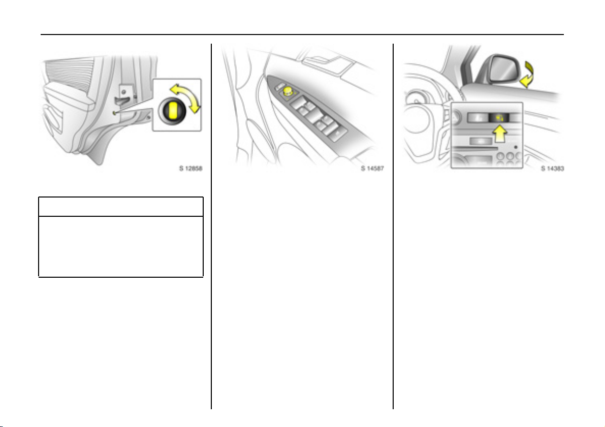
C h il d s afety lo cks
9 Wa rning
Use the ch ild safe ty locks wh ene ver
childre n are occupying the rear seats.
Disregard may lead to injurie s or
endanger life. Vehicle passengers must
be informed accordingly.
To e ngage lock, open d oor, inse rt key into
child safety loc k and turn lock from the
vertical to the horizontal position. Door
cannot then be opened from inside.
To unlock door while child safety lock is
activated, p ull up lock button and open
door from outside. Do not pull inside door
handle while child safety lock is activate d.
Exterior mirrors
Electrically adj usta ble exterior m irrors
Ad just with the four way switch in driver’s
door: move s elec tor s witch to L or R;
four way switch adjusts corresponding
mirror.
The mirror glass swivels in the same
direction as the activation of the four way
swi tch .
Heated exterior mirrors 3 - see pa ge 102.
Fold in exterior mirr ors
Manually: the exterior mirrors can be
folded in by pre ssing lightly on the outside
of the mirror hous ing.
Electrically 3: with starter switch in
positions ACC or ON, press button n and
both mirrors will fold in.
Press button n a g ain; bo th mirro rs will fo ld
to the driving position.
If a fold ed-in e lect ric mir ror has b e en
folded out manually, pressing button n
only folds the other mirror out. Pressing
button n a gain folds both m irrors back in.
Fold mirrors b ack into driving position
before driving the ve hicle.
Page 31

Locks, doors, windows 27
For the safety of pedestrians, the exterior
mirrors will swing out of their normal
mounting position in the event of a n
accident-like impact.
As exterior mirrors are convex, objects are
closer than they appear. Use interior mirror
to judge size and d istance of objects.
Do not scra pe ic e from exterior mirrors or
force them if frozen. Use a de-icer.
Automat ic anti-daz zle exterior mirrors 3
Dazzle is automa tically red uced.
Exterior mirrors dim to reduce glare
automatic ally in conjunction with the
automatic anti-dazzle interior mirror 3 see p age 28, Fig. S14 381.
Interior mirror
To adjust interior mirror, swivel mirror
housing.
Swivel lever on underside of mirror housing
to re duce dazzle at night.
Take care when driving with interior mirror
adjusted for night vision. Rear view may be
slightly distorted in this position.
Page 32

Locks, doors, wind ows28
Autom atic anti-dazzle inte rio r mir ror 3
Dazzle is automatically re duced.
With the ignition off, the mirror does not
dim.
Press button on mirror housing to turn
function on. Button will illuminate.
Press button again to turn off.
There are two light sensors in the mirror
housing. To av oid interference and loss of
fu nc tio n , d o not co v er th e se ns or s or ha n g
anything on the m irror.
Electric w indows
9 Warning
C ar e m us t be take n when o pe rating t he
electrically operated door windows.
There is a risk of injury, particularly for
children, and a danger tha t articles could
become tra pped. Vehicle passengers
must be informed accordingly.
If there are children on the rear seats,
press the switch in the driver’s door to
lock re ar win dow operation. Rear
windows can then only be operated via
th e driver’s door switch es.
Keep a close watch on the windows when
closing them. Ensure that nothing
becomes trappe d in the m as they move.
Before leaving the vehicle, remove the
ignition key in order to prevent
unauthorized operation.
Operational with key in s tarter switch
positions ACC or ON. If key is in LOCK
position or removed, windows can b e
op e rated f o r 1 0 m inutes or until d riv er’s
door is opened.
O pera te d via four s w itch es loca te d in t h e
drive r’s do or.
For incremental operation, briefly pull or
press the switch.
For a utomatic 3 opening or closing, pull or
press the switch longe r. Pull or press the
switch again to stop the movement.
Page 33

Safety func tion 3
If the window glass encounters resistance
above the middle of the window during
automatic closing, it will stop immediately
and will be opene d again.
In the event of difficulty due to frost or the
like, press the relevant window switch
several times until the window is closed.
Locks, doors, windows 29
Additional switches are located in the front
passenger’s door and the rear doors.
The rear windows do not open fully.
Child safety system for rear windows
Press z switch in drive r’s door to lock re ar
window operation.
With the lock on, rear pa ssenger windows
can only be operated via the switches in
th e driver’s do o r .
Page 34

Locks, doors, wind ows30
Sunvisors
Use the sunvisor to protect from glare by
pulling it up, d own or swivelling it to th e
side.
Sunvisors have vanity mirrors and a ticket
holder 3 on the rear.
When the vanity mirror covers are opened,
the sunvisor light 3 will illuminate.
Sl ide / ti lt su nro of 3
Operated via switch in roof lining when the
starter switch is in pos itions ACC or ON.
With key in LOCK position in the starter
switch or re move d, the slide / tilt sunroof
can be adjusted for up to 10 minutes or
until a door is ope ned.
For incremental operation, briefly press the
button. For automatic opening or closing,
press and hold the switch.
To open
Press switch rearwards; it w ill op en
automatically unless the switch is pre ssed
again in another direction, or released.
To close
Press and hold switch forwards. Release
switch when sunroof reaches desired
position.
To tilt
Press and hold switch upwards. Release
switch when sunroof reaches desired
position.
To return sunroof to its orig inal position,
press and hold switch downwards. Release
switch when sunroof reaches desired
position.
Page 35

Note
z If the top of the sunroof is wet, tilt it to
allow water to run off before opening the
sunroof.
z When carrying a roof load, check the
clearance of the sunroof, to avoid
damage.
9 Wa rning
Care must be tak en whe n operating the
sunroof. Do not p lace any objects or
body parts in the sunroof opening.
Keep sunroof clear of debris. Do not
place heavy objects on or around
sun roof.
When leaving the vehicle unattended,
ensure the sunroof is fully closed.
Locks, doors, windows 31
Page 36

Seats, interior32
Seats, interior
Front s e a ts ...... ..... ......... ......... ........ ..... 32
Re ar se ats .... ......... ......... ......... ........ ..... 37
Seat be lts . ........ ......... ......... ......... ......... 38
Child restraint systems 3 ...... .... ......... 43
Airbag system s .... ......... ......... ........ ..... 48
Storage .... ........ ..... ......... ......... .... ......... 55
Drin k h o lders ... ..... ......... ......... ........ ..... 63
Ashtrays 3... .... ......... ......... ..... ........ ..... 63
Warn ing triangle ¨ 3,
Fir s t aid k it +3. .... ......... ..... ........ ..... 64
Po wer outlets .. ..... ......... ......... ........ ..... 64
As sis t grips ...... ..... ......... ......... ........ ..... 65
Front se ats
9 Warning
Never adjust seats w hilst driving as they
could move uncontrollably.
Adjust s eat longi tudinally
To adjust, pull the handle on the front seat,
slide the se at and release the handle.
Adjusting front seat backrests
To adjust, lift the release lever, mov e sea t
bac krest to suit seating pos ition and lock in
position w hen the lever is released .
Do not lea n on the s eat b ackrest whilst
adjusting it.
Page 37

Seats, interior 33
Electrica lly a djustabl e front seat 3
9 Wa rnin g
Care must be taken when operating
electrically adjustable seats. There is a
risk of injury, p artic ularly for children and
a danger that articles could be come
tra pped .
Keep a close watch on the seats when
adjusting them .
Ve h ic le pa ss en ge r s m ust be inform ed
accordingly.
Adjusting the lumbar support 3
To adjust, turn the handwheel whilst
relieving the load on the bac krest.
Adjust lumb ar support to suit pe rsonal
requirements.
Adjusting seat height 3
To adju st, op erate leve r on sid e of s eat.
Lever pumping action
up war d : r a i se s se at
downward: lowers seat
Page 38

Seats, interior34
Seat position
Adjust driver’s sea t such that, with the
driver sitting upright, the steering wheel is
held in the area of its uppe r spokes with the
driver’s arms s lightly bent.
Slid e front passenger’s seat as far back as
it will g o.
The se at backre sts must not be tilted back
too far (recom mended max imum tilting
angle approx. 25°).
9 Wa rnin g
Adjustment
The se at position can be ad justed by
means of switches on the outboard side of
the seat.
Adjusting the longitudinal pos ition:
Move front switch forwards / backwards.
Height adjustment:
To adjust height of front part of seat
cushion, push front part of switch up /
down.
To adjust height of rear part of seat
cushion, push rear part of switch up / down.
To adjust height of entire seat cus hion,
push both front and rear parts of sw itch
up / down.
Seat backrest adjustment:
Move upper part of rear switch forw ards /
backwards.
Operate switch until desired seat position is
reached . Seat position - see next column.
Afte r adjusting the seat, a djust height of
seat belt - see page 43.
The seat backrest must not be tilted back
too far (recommended maximum tilting
angle approx. 25 °).
Important: Do not sit nearer than
10 in ches (2 5 cm) f rom t h e s teerin g
wheel, to permit safe airbag deployment.
Disregard ca n lead to injuries which c ould
be fata l. Vehicle passengers must be
informed accordingly.
Page 39

Head re straints
To adjust head restraint height, press
release button, adjust height to suit then
release the button.
Pull head restraint up to ra ise. Push head
restraint down while pressing the release
button to lower the head restraint.
Seats, interior 35
Ac tiv e h e ad restraints 3
In the event of a rear-end impact, the
active head restraints automatically tilt
forwards. The head is more effectively
supported by the head restraint and the
danger of whiplash in th e neck area is
reduce d.
Do not a tta ch objects or components that
are not approved for your vehicle to the
head restraints. These affect the protective
effect of the head restra ints and can be
prop elled through the vehicle in an
uncontrolled m anner if the driv er brak es
hard or an accide nt occurs.
Head restraint position
For m aximum protection, the middle of the
head re stra int should be at eye level. If this
is not possible for extremely tall persons,
set to highest position, and set to lowest
position for extremely small persons.
9 Wa rnin g
Disregard ca n lead to injuries which c ould
be fata l. Vehicle passengers must be
informed accordingly before moving
away.
Page 40

Seats, interior36
Removing the head restraints
Insert a suitable tool into the small hole in
the side of the guide sleeve without the
rele a s e butto n a n d de pres s the l o ck. Pres s
the release button on the other guide
sleeve and pull up the head restraint.
Stow head restraints securely in lugg age
compartment.
Do not drive with head restraints removed
if the s e at is occup ied.
Front s e at a rmres t 3
The armrest can be slid forwards. Pull up
and hold upper lever and slide the armrest
fo rw a rd s .
To return armrest to its rearmost position,
slide it back until it latches into position.
Console box in front armrest - see page 61.
Folding d own the pass e nger’s seat 3
Push front pas senger’s seat head restraint
all the way down - see page 35.
Slid e front passenger’s seat as far back as
it will g o.
Fold seat forwards by lifting b ackrest
release leve r and folding backrest down
onto seat cushion.
Page 41

To raise the seat, lift backrest release lever
and pus h backrest to upright p osition.
Push and pull on seat back rest to ensure it
is l o cked , th us av oidi ng exces siv e for war d
moveme nt in the event of a c ollision.
9 Wa rning
If longer objects, e.g. skis, are to be
carrie d on the back of the front
passenger’s seat backrest, ensure they
are not in the area in which the front
passenger’s airbag inflates or in the area
between the seat back rest and the
vehicle body. In the eve nt of a collision,
such objec ts may be thrown through the
vehicle.
The load must not hinder handbrake
op eration or gea rshifting.
Disreg ard of t h es e notes ca n lead to
injuries which may be fatal.
Rear seats
To adjust backrests, lift release lever
located on top of b ackrest and move
backrest forwards or backwa rds to desired
position.
Do not lean on seat backrest whilst
adjusting it or make adjustments while the
vehicle is moving.
When folding the rear seat back rests,
ensur e the sea t belt s are u nb uck led.
Seats, interior 37
Folding r ear seat back re sts
The luggage compartme nt can be
enlarged by folding the rear seat backrests
onto the seat cushions.
To fold rear seat ba ckrests separately,
unbuckle all three rear seat belts and
ensure front seats are not in reclined
position.
Push head restraints all the way down, lift
backrest release lever and fold backrest
forwards and down onto seat cushion.
Do not allow pa ssengers to sit on folded
bac krest, or place any unrestrained loads
on it.
Page 42

Seats, interior38
9 Wa rning
When folding the backrest, use caution beware of moving p arts.
Safe ty ne t 3 - see page 56.
Restoring rear seat backrests
Lift and push backrest up and backwards
to restore it to its origin al position. Ensure
backrest la tches into place by pushing top
of back rest and pulling it forwards again.
9 Wa rning
Ensure that the backrest returns to its
corre ct position - see pa ge 34 .
Never adjust the rear seat backrests
whil s t the veh icl e is mo vi n g. Th ey c o u ld
move in an uncontrolled m anner when
the lever has be en pulled.
Rear s eat armr est 3
The armrest can be folded down.
If the re ar ce ntr e se at is be ing u se d or th e
rear seat backrests are being folded down,
fo l d ar mr es t u p w ar ds .
Console box in rear armre st - see page 61.
Sea t belts
Thre e-stage restr aint system
Th e sy ste m comp r i s es:
z Three-point seat belts.
z Belt tensioners, with load lim iters, on the
front seats.
z Airbag systems for driver, front
passenger and rear outboard s eat
occupants.
The three stages are activa ted in sequence
depending on the seriousness of the
acc id ent:
z The automatic seat belt locking devices
prevent the be lt strap from being pulled
out and thus e nsure that the vehicle
occupants are reta ined in their sea ts.
z The front seat be lt buckles are pulled
do wnwards. As a res ult, t h e se at be l t s
are instantaneously tightened and the
occupants are mad e aw are of the
dece leration of the v ehicle at a very early
sta g e . This r ed u ce s stre ss pla c e d on t h e
body.
Page 43

Seats, interior 39
z The airbag system is additionally
trigg ered in the e vent of a serious
accident involving a frontal impact, a nd
fo r ms a sa fe ty c ush io n for t h e d r i ve r a nd
front passenger. In the event of a sid e-
im p act, t h e sid e ai r b a g sy ste m 3
protects the occupants in the front of the
vehicle, and the curtain airb ag system
protects both front and rear outboard
seat occupants.
9 Wa rning
The airbag system serves to supplement
the three-point seat belts and belt
ten sioners . Th e se at be lts mus t theref o r e
always be worn.
Disreg ard of t h es e notes ca n lead to
injuries which may be fatal. Vehicle
pa ss eng e rs m u st b e in f o rmed
accordingly.
Be sure to read the descriptions of a ll the
restraint systems on the following page s.
Three-point seat belts
The front and rear seats are equippe d with
three-point seat belts with automatic
retractors and locking de vices, allowing
fre edom of body movement when the
vehicle moves at a con s tant speed,
although the spring-tensioned belts are
always a snug fit.
The be lt has a “vehicle sensitive retractor”
which is designed to lock during heavy
acceleration or deceleration in any
direction.
9 Warning
Always we ar y our seat belt, and th at
means also in urban traffic and when you
are a rear seat pa ssenge r. It ca n save
you r life!
Pregnant women too must always wear a
seat b elt, keeping the lap belt low and
snug on the hips and pelvis (not the waist
or abd om en, whe re a ctuating b elt
te nsi o ners c o uld ca u se s er i o u s inju r y i n
the event of a collision).
In the event of an accident, persons not
wearing seat belts endange r their fellow
occupants and themselves.
Control indicator X for driver’s seat be lt
re min der - se e p a ge 6 8.
Control indicator k for front passeng er’s
seat belt reminder 3 - see page 42.
Seat belts are design ed to be used by only
one person at a time . They are only
suita ble for children a ged up to 12 or
smaller than 150 cm if used in conjunction
with a child restra int 3.
For children u p t o 12 ye ars of a ge, we
recommend the V auxhall child restraint
system 3 - see pag e 43.
Page 44

Seats, interior40
Belt force limiters
Load limiters on the front seats reduce the
impac t on the seat occupan t’s body from a
tensioning b elt, in the ev ent of a severe
frontal collision. The belt force is controlle d,
to reduce the risk of b elt-inflicted injury.
Inspection of belts
Periodically inspect all parts of the belt
system for damage and to make sure they
are functioning properly.
Have damaged parts replaced. After an
accident, belts and triggered belt
tensioners must b e replaced by new ones.
Do not perform any alterations on the
be lts, the ir an chora ges , t h e autom atic
retractors or the belt buckles.
Make s ure that be lts are not dam aged or
trapped by sharp-edged objects.
Belt tensioners
The seat belt systems on the front seats
incorporate belt tensioners housed in the
belt buckles an d seat belt retractors.
In the event of frontal collisions or sideimpacts of a certain severity, belt buckles
and seat belt retractors tighten the seat
belts; the shoulder and lap belts are
instantaneously tightened to fit the
occupant’s body more snugly.
The be lt buckles and seat be lt retractors
will remain locked afte r actuation (where
some noise will occur and s moke may be
re l ea s e d) .
Belt tensioners are not d esigned to activate
in the e vent of rear-im pacts, minor side-
impacts, rollovers or minor frontal
collisions.
Actuation of belt tensioners
The belt tensioners actuate only once and
must be replaced b y a workshop after
activation.
9 Wa rnin g
The belt tensioners are ope rational only
when control indicator v is unlit.
If the control indicator does not flash
briefly whe n the ignition is on, stays lit,
illuminates or flashes whilst driving, the
belt tensioners or the airbag systems may
not function correctly.
Have both systems inspected by a
workshop.
The seat be lts remain fully opera tional
even when the belt tensioners have been
actuate d.
Page 45

Seats, interior 41
Belt tensioners control indicator
The seat belt tensioners are monitored
electronic ally together with the airbags,
and their operational readine ss sh own by
the red control indicator v in the
in st r u me nt clus t er.
When the ignition is switche d on, the
control indicator flashes several times then
e x t i ng uis h es . If it d o es n o t f l a sh , st a ys l i t ,
illuminates or flashes whilst driving, there is
a fault with the belt tensioners or in the
ai r b ag sy ste ms. Th e s ystem s m ig ht no t
therefore be triggered in the event of an
accident (see also pa ge 52 ).
9 Wa rning
The system’s integ rated self-diagnostics
allow s faults to be quickly reme died.
Important
z Accessories not released for your vehicle
type and other objects must not be fixed
or placed within the action zone of the
belt tensioners, as they m ay result in
injury if the belt tensioners are triggered.
z Do not mak e any modifications to the
components of the belt tensioners, as
this may result in unintended actuation
of the belt tensioners, rendering the
vehicle unroadworthy and causing
serious personal injury.
9 Warning
Imprope r handling (e.g. removal or
installation) can activate the belt
tensioners – risk of injury.
z The belt tensioner and airbag system
control electronics can be found in the
centre console area. In order to avoid
malfunctions, do not store magnetic
objects in this area.
z When using the rear s ea ts, ensure that
the front seat belt components are not
damaged by shoes or other objects.
Avoid dirt getting in the retractors.
z The belt tensioners only actuate once,
ind ic ated by continuous illumina tion of
control indicator v in the instrument
cluster. Deployed belt tensione rs must be
replaced by a workshop.
z Whe n disp osing o f t h e v ehicl e, obs erve
the applicable safety regulations. Take
the vehicle to a recycling company for
disposal.
Have the cause of the fault remedied by
a workshop.
Page 46

Seats, interior42
Using th e be lts
Fitting the belt
Pull the belt out evenly from the retractor
and guide it over the shoulder, m aking
certain that it is not twisted.
Insert the la tch plate into the buckle.
The se at backre st must not be tilted back
too far (the recommended m aximum tilting
angle is approx. 25°).
The lap belt must not be twisted and must
fit snugly across the body. Tension the belt
frequently whilst d riving by tugging the
diagonal part of the belt.
9 Warning
On pregnant women in particular,
the lap b elt must be positioned as low as
possible across the pe lvis in order to
prevent pressure on the abdomen.
Keep knees pointing straight forward so
that driver’s side knee bolsters can help
prevent submarining unde r the seat belt in
the event of a collision.
Bulk y clothing prevents the belt from fitting
properly. The belt mu st not rest against
ha rd or fragile objects in the pockets of
you r clothing (e.g. ballpoint pens , keys ,
spectacles) be cause these could cause
injury in the ev ent of a collision. Do not
place an y object s (e.g . handbags) betwee n
the belt and your body .
F r o nt p ass eng e r’s seat b e lt rem inde r k 3
Illuminates for approx. 4 seconds when
ignition is switched on.
When the engine is running, if the front
passenger’s seat is occupied and the b elt is
not enga ged, the control in dicator will
flash for approx. 90 seconds an d then
illuminate until the belt is fastened
correc tly (control indicator will extinguish
imm ediately).
If vehicle speed exceeds approx. 14 mph
(22 km/h), the control indicator will fla sh for
app rox. 90 seconds along with a warning
chime, and then illum inate until front
passenger’s seat belt is fastened.
Control indicator X for driver’s seat be lt
re min der - se e p a ge 6 8 .
Page 47

Seats, interior 43
Child restraint systems 3
Vauxhall child restraint systems are
designe d specifically for your vehicle and
thus provide optimum safety for your child
in the even t of an impact. The use of a
Vauxhall child restraint system is therefore
recommended.
If a different child safety s eat is used, follow
the manufa cturer’s instructions for fitting
and us e.
9 Wa rnin g
Seat belt height adjustment
of front seat belt upper anchorage points
z Do not a djust height w hilst driving.
z Squeeze release buttons together and
slide adjuster up or down to de sired
position.
z Ensure sliding height adjuster latches
into position.
Height adjuster can also be moved up
without squeezing release buttons.
Removing the belt
To remove the belt, press the red release
button on the belt buck le; the belt will
retract automatically.
Guide the belt as it retracts, to prevent
personal injury a nd damage to interior
surfaces .
Alw ays en s ure you position t he rele ase
button so that you can unbuckle the seat
belt quickly if necessary.
Disregard of these instructions may lead
to injuries or endanger life .
Selec ting the right system
Your child should be transported facing
rearwards in the vehicle as long as
possible. The child’s neck area is still very
weak a nd in an accident they suffer le ss
stress in the semi-prone rearward position
than when sitting upright.
Page 48

Seats, interior44
Note
z Children under 12 years or under 150 c m
ta ll should only travel in an app ropriate
child safety seat.
z Never carry a child whilst travelling in the
vehicle. The child will become too heavy
to hold in the event of a c ollision.
z When transporting children, use a child
restraint system tha t is suitable for the
child's weight, age and heig ht.
z Ensure that the child restraint system to
be installed is comp atible w ith the
vehicle type.
z You should always observe the
instructions on installation and use
supplied with the child restraint system.
z Do not stic k anything on the child
res t r a in t sy ste ms a nd d o no t c o ve r the m
with any other materials.
z O nly allow children to enter and e xit the
vehicle at the side facing away from the
traffic.
z A child restraint system whic h has been
subjected to stress in an accident must
be replaced.
z W hen the child restraint system is not in
use , s e cure th e se at with a s ea t belt o r
rem o ve it from the vehicle.
z The covers of the Vauxhall child restraint
system can be wiped clean.
The following V auxhall child re straint
systems have been approved for
insta llation in y our Antara:
Group, weight and ag e
1)
class
00+From birth - 10 kg,
Vauxhall
sy ste m
Baby Safe
0 - 10 months
From birth - 13 kg,
0 - 2 years
I From 9 - 18 kg,
Duo ISO FIX
8 months - 4 years
II
From 15 - 25 kg,
Kid
3 years - 7 years
From 22 - 36 kg,
III
6 years - 12 years
1)
We rec ommend th e use of each system
until the ch ild rea ches the u pp er
weight lim it.
If child restraint systems of other
ma nufac ture a re t o be insta lled, ensure
that they conform to the app ropriate
safety regulations.
Page 49

Seats, interior 45
Permissible options for fitting a child safety seat
We ight and age class On front passenger’s
seat
0:
up to 10 kg
or approx.
10 months
0+:
up to 13 kg
or approx.
2 years
I:
9 to 18 kg
or approx.
8 months to 4 years
II :
15 t o 25 kg
or approx.
3 to 7 years
II I:
22 t o 36 kg
or approx.
6 to 12 years
XU, + X
XU, + X
XU, +, ++X
XUX
XUX
On outboard rear
seats
On c entr e rear se at
U
= Universal suitability in conjunction
with the three-point seat belt.
+
= Vehicle seat with ISOFIX mounting
available. When mounting with
ISOFIX, on ly IS OFIX child r estraint
systems that have been approved
for the vehicle may be used.
++
= Vehicle seat with ISOFIX fixings
available. For use of ISOFIX and
top tether fixings, universal ISOFIX
child restraint systems may be
used.
X
= No child restraint system
permitted in this weight a nd age
class.
9 Warning
Disregard of these instructions may lead
to injuries or endanger life .
Page 50

Seats, interior46
ISOFIX child restraint systems 3
The instructions accompanying the ISOFIX
child restraint system are to be expressly
followed.
IL
= Suitable for particular
ISOFIX child restraint
systems specified in the
list.
These ISOFIX systems are
of th e ’vehicle -specific’,
’restricted’ or ’semiuniversal’ ty pe.
IUF
=Suitable for ISOFIX
forward-facing child
restraint systems of
universal category
approved for use in this
weigh t and age clas s.
X
= No child restra int system
permitted in this weight
and age class.
Size class Descri ption
A - ISO/F3: Forward-fac ing
child restraint sy stem for
children of maximum size in
the weight class 9 to 18 kg.
B - ISO/F2: Forward-fac ing
child restraint sy stem for
smaller childre n in the
weight class 9 to 18 kg.
B1 - ISO/F2X: Forward-facing
child restraint sy stem for
smaller childre n in the
weight class 9 to 18 kg.
C - I SO/R3 : Rea r-facing
child restraint sy stem for
children of maximum size in
the weight class up to 13 kg.
D - ISO/R2: Rear-facing
child restraint system for
smalle r child ren in the
weight class up to 13 kg .
E - ISO/R1: Rear-facing
child restraint system for
young children in the
weight class up to 13 kg .
Page 51

Permissible options for fitting an ISOFIX child safety seat
We ight and age class Size class Fixture On front passenger’s
seat
0:
up to 10 kg
or approx.
10 months
0+:
up to 13 kg
or approx.
2 years
I:
9 to 18 kg
or approx.
8 months to
4 years
EISO/R1X IL X
EISO/R1X IL X
DISO/R2 X IL X
CISO/R3X IL X
DISO/R2 X IL X
CISO/R3X IL X
BISO/F2X IUF X
B1 ISO/F2X X IUF X
AISO/F3 X IUF X
On outboard rear
seats
Seats, interior 47
On c entre rear se at
Page 52

Seats, interior48
Mou nting brackets for ISO FI X c hild
restraint sy stems
The brackets located betw een the backrest
and sea t cushion are used for mounting
ISO F IX ch ild r es tr a i nt sy ste ms.
The instructions accompanying the ISOFIX
child restraint system are to be expressly
followed.
Only ISOFIX child restraint systems
approved for the vehicle may be used.
Anchors for Top-Tether c hild restraint
sy s te ms
The top tether anchors located on the rear
of the backrests are designed to hold child
restra ints which come equipp ed with top
tether anchor attachments only.
Please be sure to follow the instructions
provided with the Top-Tethe r child
restraint system.
For u s e of IS OF IX and To p-Te th e r fixings,
universal ISOFIX child restraint systems
may be us ed.
Airbag systems
Front airb ags
Th e fro n t airb a g sys tem is id e ntif ied b y the
word “ Airbag” on the steering wheel and
abov e the glove compartment.
The front airbag system comprises:
z an airbag with an inflator in the steering
wheel, and a second one behind a trim
panel above the glove compartment,
z the control electronics,
z the front impact sensor,
z the airbag system control indicator v in
the instrument cluster.
Page 53

Seats, interior 49
The fron t airbag system is trig gered:
z depending on the severity of the
accident,
z depending on the type of impa ct,
z within the range shown in the illustration,
z inde pendently of the side airbag 3 and
curtain airba g systems.
Examples:
z Impact against a non-yielding obs tacle;
the front airbags are triggered at low
vehicle speed s,
z Impact against a yielding obstacle (such
as another v ehicle); the front airbags are
only trig gered at a higher vehicle speed.
When trigg ered, the driver’s and front
passenger’s airbags inflate in m illiseconds
and form safety cushions for the driver a nd
front passenger. Forward movement of
driver and front passenge r is checked an d
the risk of injuries to the upper body and
head thereby substantially red uced.
z No im pairment of v iew w ill occur, as
airbags inflate and deflate so quickly.
9 Warning
The front airbag system provide s
optimum protection when the seat, seat
belt, backrest and head restraint are
correctly adjusted.
Adjust the driver's seat according to the
occupant's height such that, with the
driver sitting upright, the steering wheel is
held in the are a of its upper spokes w ith
th e driver's ar ms s lig htly bent.
The driver’s seat should be as far b ack as
possible without compromising the
driver’s ability to re ach the p edals,
stee ring wheel o r co ntr o ls .
The front passenger’s seat should be as
far bac k as possible, with the backrest
upright. Do not place the head, body,
hands or feet on the cover of the airbag
system.
Do not place objects, children or pets in
the area in w hich the airbags infla te.
The front airbag system will not be
triggered in the event of:
z the ignition being switched off,
z minor frontal collisions,
z accide nts i n wh ich th e vehicle o ver t u rns,
z collisions involving a side or rear-impa ct
where it would not be of benefit to the
occupants.
9 Wa rnin g
Se at be lts mu st the r ef o re al ways be worn .
The front airbag system serves to
supplement the three-point seat belts.
If yo u do not wear you r seat be lt , y ou ris k
being seriously injured, or even thrown
from the vehicle, in the event of an
accident.
The belts help to maintain occupants in
the correct seating position for the front
airbag system to provide effective
protection in the event of an accident.
Page 54

Seats, interior50
Sid e a irbag s 3
The side airbags are identified by the word
"Airbag" on the outboa rd sides of the front
seat b ackrests, and protect front sea t
occupants in the event of a severe side-
impac t.
The side airbag system comprises:
z an airbag with inflator in the outboard
sides of the driver's and front
passenger's seat backrests,
z the control elec tro n ics ,
z the side-impact sensors,
z the a irb a g sys t em s co nt r ol in dic a t o r v in
the in st r um e nt clus t er .
The side airbag system will be triggered :
z depending on the severity of the
accident,
z de pending on the type of impact,
z within the range shown in the illustration,
z indep endently of the front airbag
system.
When triggered, the side a irbag infla tes in
milliseconds and forms a safety cushion for
the driver a nd/or front passe nger in the
respective door area. The risk of injury to
the upper body and pelvis in the event of a
side-imp act is thereby substantially
reduced.
9 Wa rnin g
The re m u st be no obj ec ts in th e area in
which the airbag inflates or in the area
between the seat ba ckrests and the
vehicle body.
Do not place ha nds, arms or othe r body
parts on the covers of the airbag systems.
Important information - see p age 53.
The three-point s eat belt must alway s be
correctly fitted - see page 39 .
Page 55

The side airbags will not be trigg ered in the
event of:
z the ignition being switched off,
z frontal collisions ,
z accidents in which the vehicle overturns,
if lateral impa ct is insufficient for side
airb ag de ployme nt,
z collisions involving a rear-impa ct,
z collisions involving a side-impact outside
the passenger c ell.
Seats, interior 51
Curtain airbags
The curtain airbag system is identified by
the word " Airbag" on the roof frame, and
protects front seat and rear outboard seat
oc cup ants i n the eve n t o f a s evere side -
impact.
The curtain airbag system comprises:
z an airbag with inflator in the roof frame
above the doors on the driver’s and
passenger’s side respectively,
z t h e control elect ron ics,
z the side-impact sensors,
z the airbag systems control indicator v in
the instrum ent cluster.
The curtain airbag system will be triggered:
z depending on the severity of the
accident,
z depending on the type of im pact,
z within the range shown in the illustration,
z tog ether with the side airbag system,
z ind ependently of the front airbag
sy ste m.
Page 56

Seats, interior52
When trigg ered, the curtain airbag inflates
in milliseconds an d provide s a safety
barrier in the head area on the respective
side of the vehicle. This reduces the risk of
injury to the head considerably in the event
of a side-im pact.
9 Wa rning
The re m us t be n o o bjects in the area in
which the airbag inflates. Do not place
han d s , a rm s or ot he r bo d y p ar t s o n th e
covers of the airbag systems.
Nev er secure anything to the roof by
routing ropes through the doors or
windows, to av oid obs tructing inflatio n of
the curtain airbags.
Important information – see page 53.
The three-point seat belt m ust always be
corre ctly fitted – see page 39.
The curtain airbags will not be triggered in
the event of:
z the ignition being switched off,
z fronta l collisions,
z accidents in which the vehicle overturns,
if lateral imp act is insufficient for curtain
airbag deployment,
z collisions involving a re ar-impact,
z collisions involving a side-impact outside
the passenger cell.
Airb ag cont rol indica tor v
The front airbag system, side airbag
system 3 and curtain airbag system
are monitored electronically together with
the belt tensioners, and their operational
readiness is shown by the red control
indicator v in the instrument cluster.
When the ignition is switched on, the
control indicator flashes several times then
extinguishes. If it does not flash, stays lit,
illuminates or flas hes whilst driving, there is
a fa ult in the airbag system s or with the
belt tensioners. The systems might not
therefore be triggered in the event of an
acc id ent (see also p age 41).
Page 57

Seats, interior 53
9 Wa rning
Have the cause of the fault remedied by
a workshop.
The system's integral self-diagnosis facility
allows faults to be quickly remedied.
9 Wa rning
Disreg ard of t h es e ins t r uctio n s may lead
to inj u r ies or e nd ang er li fe.
Imp or tant
z Accessories not released for your vehicle
type and othe r objects must not be
affixed or place d in the area in which the
airbags inflate, as they could cause
injury when the airbags are triggered.
z Do not place any objects between the
airbag systems and the v ehicle
occupants; danger of injury.
z Only use the hooks on the assist grips in
the roof frame to hang up light a rticles of
clothing or coat hangers. Do not place
any objects in the pock ets of t he h anging
it em s; risk o f inju r y.
z Do not stic k or place an ything on the
stee ring whee l, instr u me nt p anel , f ront
seat backrests in the vicinity of the
airbags and seat areas or c ov er the m
with other m aterials.
z The airbag systems and b elt tensioner
control electronics can be found in the
centre console area . In order to avoid
malfunctions, d o not store magnetic
objects in this area .
z Use only a dry cloth or interior cleaner to
clean the steering wheel, instrument
panel, front seat backrests, roof fra me
and seat area of the front seats. Do not
use any ag gressive cle aning agents.
z Only protective covers which are
approved for your vehicle with s ide
airbags 3 m ay be fitted on the front
seats. When fitting the protective covers,
make sure that the a irb ag units on the
outboard sides of the front seat
backrests are not covered.
z The airbag systems are triggered
ind ependently of each other, depending
on the severity of the accident a nd the
type o f im pact. The side airbag sys tem 3
and the curtain airbag system are
triggered together.
z During off-road driving e specially,
airbags can also inflate in moderate to
severe non-collision situations such as
when slamming the undercarriage or
other solid components of the vehicle in
a dip in the driving s urfac e.
z Each airbag can be triggered only once.
Once triggered, an airb ag must be
replaced imm ediately by a workshop.
Page 58

Seats, interior54
z Afte r airbags de flate, you may notice a
burning smell, smoke and white powd er
in the interior, which is normal. Although
they may cause skin or eye irritation,
these substances are non-toxic.
z Hazard warning lights may flash and
lock ed doors may be un lock ed
automa tically when airbags deploy 3.
z The speeds, directions of movement and
deformation properties of the vehicles,
and the properties of the obstacle
concerned, determine the severity of the
accident and trig gering of the airbags.
z The de gree of damag e to y our v ehicle
and the resulting repair costs alone a re
not indicative that the criteria for
triggering of the airba gs were met.
z Do not perform any modifications to the
com ponents of the airbag systems, as
this will render the vehicle unroadworthy.
9 Wa rning
The s ystems can be trigge red ab ruptly
and cause injury if they are handled
im p r o pe r l y.
z We recommend having the steering
whe el, the ins trume nt pan el, all panelling
parts, the door seals, handles and the
front se ats r em o v e d by a w o r k s h op in
the event of airbag deployment.
z When disposing of the vehicle, observe
the applicable safety regulations. Tak e
the vehicle to a re cycling compa ny for
disposal.
9 Warning
Child restraint systems as well as other
hea vy o bje ct s m u st n e ver be ca rrie d o n
the la p of passengers; risk of fatal injury .
Use of child restraint systems 3 on front
passenger’s seat
9 Wa rnin g
No child restraint system m ay b e
installed to the front passenger’s s eat.
Danger to life.
Page 59

Notes on loading the veh icl e :
See page 59.
9 Warning
Do not place any heavy or sharp objects
on the c over.
Loose objects in the lugga ge
compartment should be secured safely.
Seats, interior 55
Storage
Luggage com part ment cover
To close
Pull lug gage compartme nt cover toward s
rear of vehicle using handle and insert
retainers into brackets on either side of
luggage compartment.
To open
Remove luggag e compartment cover from
side brackets. I t rolls up automatically.
To remove
Open luggag e com partment cover.
Pull socket on either side of cover towards
centre of ve hicle, lift and remove cover
from the side guides.
Fit in reverse order.
Page 60

Seats, interior56
Safety net 3
The safety net can be mounted behind the
rear seats or, if the rear se at backre sts are
folded, in front of the rear seats.
Passengers must not b e transported
be hin d th e s a f ety ne t.
Fitting
The re a re four installation openings in the
roof frame, two located in front of and two
behind the rear seats.
When fitting behind the rear seats, remove
the luggage compartmen t cove r -
see page 55.
When fitting in front of the rear seats, fold
down rear seat backrests - see pag e 37.
Open aperture covers on the roof frame
and insert top corners of safety net into
large apertures in roof fra me and secure by
sliding them into the smaller apertures.
In front of and be hind the re ar seats on
both sides of the vehicle are the hook
holders (lashing eyes) for the lower strap
hooks.
Hang strap hooks in the tw o lashing eyes.
Pull on the straps to take up any slack.
Page 61

Seats, interior 57
9 Wa rning
Do not stack loads higher than the upper
end of the safety net.
Av oid applying exces sive force to the
safety net or hanging heavy items from it.
Do not place loads b ehind the safety net
which have sharp edges that could pa ss
through the net in the event of heavy
braking, for e xample.
Removing
Loosen strap s by pulling up strap adjusters
and re move the strap hooks from the
lashing eyes.
Pull top corners of safety net from the
smaller apertures into the larger apertures
and re move .
Designed for carrying s mall, light items
only, the luggage floor net 3 he lp s kee p
loads from moving during sharp turns or
quick starts and stops.
To insta ll: attach the four net hooks to the
lashing eyes mounted on the luggage
compa rtment floor.
9 Wa rnin g
Do not carry heavy objects in the
lug gage floor ne t. Loos e objects in the
lug gage compartme nt shou ld be secured
saf ely.
Las hing ey es
Lashing eyes are mounted on the luggage
compartment floor, to enable loads to be
secured in pos ition using lashing straps 3
or a lug gage floor net 3. Two lashing eyes
are located in front of the rea r seats for
fitting a safety net 3 - see pag e 56.
Page 62

Seats, interior58
FlexOr ganizer 3
Flexible system for dividing the luggage
compartme nt or s ecuring loads.
The system consists of:
z adapters
z variable partition net
z mes h p o c ke ts for th e side w a lls
z hooks in the luggage compartment
Components are mounted in the two guide
rails in the side walls of the luggage
compartme nt by means of adap ters or
hooks.
Variable partition net
Insert an adapter in ea ch rail: fold up
ha ndle plate , ins ert adap ter in upper and
low er groove of rails, move to de sired
position.
To l ock the a dapter , swiv el th e hand le
plate up. Compress the rods of the
partition ne t slightly and insert in
corresponding openings of the adapter.
The longer rod must be ins erted in the
up per ad apter.
Hooks and mesh pocket
Insert the hooks in the desired position in
the rails: insert the hook in the upper
groove on the rail and press in the lower
groove. The mesh pocket can be hung from
the hooks.
Removing
Press the pa rtition net rods together and
remove from the adapters.
Adapter: fold open the retainer, release the
adapter from the lower groove and remove
from the up per groove.
Release the hooks from the rails.
Page 63

Luggage com part ment storage 3
Trays on both sid es of the luggag e
compartment floor.
Luggage comp artment under floor
storage 3
To access the unde r floor storage, push
both levers on floor cover towards the
ha ndle - see pag e 17 3. Pull floor cover
up wa r d s b y the ha nd le a n d h a ng th e hoo k
to the upper part of the tailgate opening.
9 Warning
Do not allow objects to p rotrude above
th e top o f the un der flo o r s t orag e, to
avoid damage to the storage area and
the lugg age compartment floor.
Seats, interior 59
Not es o n load ing the vehicl e
z Heavy obje cts in the luggage
compartme nt should be place d as far
forward as possible. If obje cts a re to be
sta c k ed, t he hea vi er o bje cts sh ou l d be
placed at the bottom .
With rear seats in the folded position, or
with safety net 3 installed behind rear
se a t s, ob j ec ts m u st n o t b e stack ed
hig her than the seat backrests.
Unsecured obje cts in the luggage
compartment would be thrown forward
with great force in the event of heavy
braking, for e xample.
z Secure heavy obje cts w ith lashing
straps 3 attached to the lashing e yes. If
he avy loads slip when the vehicle is
braked heavily or drive n around a be nd,
the handling of the vehicle may change.
z Secure loose items in lugga ge
compartme nt using FlexOrganizer 3 or
lug gage floor ne t 3 to prevent sliding.
z When transporting objects in the
lug gage compartment, fit safety net 3 -
see page 56.
Page 64

Seats, interior60
z Close the luggage compa rtment co ver to
prevent the objects from being reflected
in t h e r ea r w i nd ow .
z If the backrests are not folded down
when transporting objects in the
lugga ge c ompartment, they m ust be
engaged in their uprigh t pos ition see page 3 7.
z Do not allow the load to protrude above
the upper edge of the rear seat
backrests, or if the rear seat backrests
have been folded down onto the seat
cush ions, a bove the uppe r edge of th e
front seat backrests.
z The w arning triangle 3 and first aid kit 3
should alway s be freely a cces sib le.
z No objects should be placed on the
lugga ge c ompartment c over or the
ins trum ent pan e l. They a re re flec te d in
the glas s, obstruct the driver’ s view a nd
will be thrown through the vehicle in the
event of heavy braking, for e xam ple.
z No objects should be stored in any of the
airb ag inflat ion zon es , as inju ries may be
caused when the airbag is triggered.
z T h e lo ad m us t n ot o bs tr u ct t h e op era tio n
of the pedals, handbrak e and gearshift
lever or hinder the freedom of movement
of the driver. Do not place any unsecured
objects in the interior.
z Bulky objects should not be transported
with the tailgate open or aja r, otherwise
poisonous exhaust fumes may enter the
vehicle.
z W eights, payload and roof load -
see page 216.
z Driving with a roof load (see also
page 124) increases t he s ensitivity of th e
vehicle to crosswinds and has a
detrimental effect on vehicle handling
owing to the higher centre of gravity of
the vehicle.
9 Warning
Disregard of these instructions m ay lead
to injuries or endanger life. Vehicle
passengers must be informed
accordingly.
Stowage com partm ent s
Glove compartment
To open, pull handle upwards.
The glove com partment will illuminate
wh e n op ened .
Th e glo ve com par tment p artiti o n can b e
re mo v ed fr om it s gr oo v e.
Store the partition in the groove on the far
left-hand side of the glove compa rtment.
9 Wa rnin g
Do not drive with glov e c om p art ment
open; risk of injury in the event of heavy
braking or a collision.
Glove compartment cooling 3 see page 102.
Page 65

Seats, interior 61
Sun glas ses hol d e r
To open: push the rear part of the front
reading lights cov er.
To close: pull up cover and push it until it
latches into place .
Do not store heavy items in the stowage
compartment.
Console box in front armrest 3
To open: pull up lowe r lev er and lift the lid.
To c los e: lower lid and p us h it down until it
latches into position.
To use the tray 3: ensure armrest is in its
rearmost position, p ull up on uppe r le ver
and lift the lid.
Cons ole b ox in rear armrest 3
To open: pull up lid of re ar ce ntre armrest.
To close: lower lid and push it down until it
latches into position.
Page 66

Seats, interior62
Console net 3
Located in the driver’s footwell.
Fro nt pa ssenger’s seat undertray 3
Pull up on front of tra y the n pull it forw ards.
Push the tray towards the seat to return it
to its original position.
Storage compa rtment 3
Located in rear of centre console.
To open: press button above the stora ge
compa rtm ent.
Page 67

Seats, interior 63
Ca rd h old er
Located below in strument panel on driver’ s
side. Insert a card into the slot for
co nven i e nt us e .
Coin storage
Open by pulling h andle o n co in s tora ge
door (located below card holder) towards
you. Push door firmly to close.
Ashtrays 3
To be used only for ash and not for
comb ustible rubb ish.
9 Wa rnin g
Disregard of these instructions may lead
to inju r ies or e n dan g er life . V ehicle
pa s seng ers m u st be in f o rmed
accordingly.
Dr ink h o ld ers
Located in the front 3 and rear of the
centre cons ole.
The front drink holde r is a fixed size.
The rea r drink hold er is flexible, allowing
diffe rent size drink containers to be stored.
To open: press button above rear drink
holde r.
Page 68

Seats, interior64
Warning triangle ¨ 3,
First ai d k it +3
Your first aid kit and wa rning triangle can
be acco mm od ated below the floor cov er in
the luggage compartment.
Portable front as htray 3
Located in front drink holder.
To open: gently lift up lid. Illuminates
depending on outside light conditions.
To e mpty: rotate upper part of ashtray
anticlockwis e and remove .
After us e, close lid firmly.
To replace battery: remove screw on
ashtray lid and replace with CR2032
(or equivalent) battery.
Power outlets
Cigarette lighter )
With starter switch in positions ACC or ON,
push the cigare tte lighte r in all the w ay.
Heating up ce ases once element is
glowing; cigarette lighter pops up
automatically. Withdraw lighter.
Page 69

Seats, interior 65
Accessory sockets
Located in the rea r centre console between
the front seats and in the rig ht-hand side of
the lugga ge c ompartment 3 .
Operational with starter switch in positions
ACC or ON.
Pull the cap out to use the accessory
socket, and repla ce it w hen not in use.
The sock et for the cigarette lighter can a lso
be used to conn ect electrical accessories
when the ignition is switched on.
Us e o f acce sso r y so cke ts wh ile t he e ngin e is
not running will discharge the battery.
The max imum powe r require ment of
electrical acce ssories mu st not exceed
120 watts.
Do not connect any current delivering
accessories, e.g. electrical charging
devices or batteries.
Connected electrical accessories must
comply with the EC stand ard in terms of
electromagnetic comp atibility
requirements laid down in DIN VDE 40 839,
otherwise vehicle malfunctions m ay occur.
The use of non-authorised accessories may
cause damage to the socket.
Assist grips
Located above the driver’s door 3, the
front pas senger’s door and both re ar
doors.
Pull grip down and hold to assist when
entering or exiting the vehicle. Grips swing
back up automatically when released.
Rear door assist grips also inc lude coat
hangers.
Page 70

66 Instruments, controls
Instruments, controls
Con tro l indicators .... ..... ......... ........ ..... 66
Instrume nt dis play ........ ......... ........ ..... 71
Info rmatio n display ...... ......... ........ ..... 72
Display of current tyre pressure 3 .... 87
Che ck con tro l 3 ... .... ......... ......... ......... 87
Warning bu zzers .. ......... ......... .... ......... 88
Wind scre en wipe r ......... .... ......... ......... 88
Control indicators
The control indica tors described he re are
not present in all vehicles. The descriptions
howe ve r, apply to all instrumen t versions.
The colours of the control indicators m ean:
z Re d Danger, im portant re minder,
z Yellow Warning, information, fault,
z Green Confirm ation of a ctivation,
z Blue Confirm ation of activation.
u
ABS ( Anti-lock Brak e S ystem)
see page 145.
4
Brake system
Illuminates in red w hen ignition is switche d
on. Extinguishes after engine is started.
Illuminates when engine is running if
handbrake is applied and/ or fluid le vel for
brak e hyd raulics is too low.
9 Wa rnin g
If it illuminates when the handbrak e is not
applied: stop vehicle; interrupt y our
journey immediately. Consult a
workshop.
g
Trailer indic ator 3
Illum inates in green when a traile r is
connected to the vehicle. Extinguishes
when the trailer is disconnec ted.
Further information - see pag e 142.
Page 71

Instru ments, controls 67
r
Parking distance sensors 3
Illuminates in yellow when ig nition is
switched on.
If it stays illuminated while driving, there is
a fault in the system - see pag e 139.
5
DCS (Descent Control System)
Both control indicators illuminate w he n
ignition is switched on.
Green; illuminates when DCS is ready for
opera tion. Flas hes during driving when
DCS is in operation, afte r pressing the
DCS button.
Yellow ; flashes to indicate system is not
ready for conditions to operate.
Illuminates to indicate there is a fault in the
system.
If the yellow control indicator flashes or
illuminates during driv ing, friction mate rial
needs to cool down: drive the vehicle
without braking as much as possible.
Further information - see page 1 35.
B
AWD ( All Whee l D rive ) 3
Illum inates in yellow when ignition is
switched on, then extinguishes.
If it flashes during driving, the AWD system
is temporarily disabled.
If it illuminates, there is a fault in the
system. Consult a workshop as soon as
possible.
Further inform ation - see page 118.
7
ESC Activ e & W arn ing
(Electronic Stabil ity Contro l)
see page 133.
A
ESC Not Re ad y
see page 133.
J
ESC OFF
see page 133.
q
Automatic headlight range adjustment 3
Illuminates in yellow whe n ignition is
swi tch ed on, the n ex tinguis hes .
Com es on during driving to indicate a fault
that requires immediate attention. Consult
a workshop as soon as possible.
Further information - see pag e 94.
W
C ool ant temp era ture
Illuminates in red when ig nition is
swi tch ed o n, then ex tinguis hes .
If it illuminates w hen the engine is running:
stop vehicle and switch off engine. Coolan t
temperature is too high; danger of engine
dam age. Check coolant level.
9 Wa rnin g
Allow engine to cool down before
removing c oolant filler cap.
Further information - see pag e 192.
Page 72

Instruments, controls68
o
Electron ic im mobil iser
Illuminates in red when ignition is
switched on, then extinguishes.
If it remains illum inated when the ignition is
on, there is a fault in the im mobiliser
system; the engine cannot be started see page 18.
9
Door open
Illuminates in red when a door is open.
3
Engine electronics,
transmission electronic s 3
Illuminates in yellow when ig nition is
switched on, then extinguishes.
If it illuminates d uring driving;
there may be a fault in the engine or
transmission electronics: interrupt your
journey and consult a workshop as soon as
possible.
Further information - see page 1 31.
v
Airbag systems 3, be lt te nsioners
see page s 40, 48.
1
Ta ilgat e op en
Illum inates in red when ignition is
switchedon, then extinguishes.
Illum inates when tailgate is open or not
securely latc hed.
Tailgate - see page 22.
X
Drive r’s seat belt remi nder
Illum inates in red when ignition is
switchedon, then extinguishes.
When the engine is running, if driver’s seat
belt is not engag ed, it will flash for approx.
90 seconds and then illuminate until
driver’s seat belt is fas tened.
If vehicle speed e xceeds approx . 14 mph
(22 km/h), control indic ator will fla sh for
approx. 90 seconds along with a w arning
chim e a nd then rem ains illuminated until
driver’s seat belt is fas tened.
Seat belts - see page 39.
O
Turn signal lights
The relevant control indicator flas hes in
green when the turn signal is on.
Rapid flash; failure of a turn signal bulb or
the corresponding fuse or fa ilure of a trailer
turn signal bulb 3. Both control indicators
flash when the hazard warning lights are
active.
Further information - see pag es 10, 91.
Bulb re placem ent - see pag e 18 2.
Fuses - see page 178.
Y
Low fuel level
Illuminates in yellow whe n ignition is
swi tch ed on, the n ex tinguis hes .
If it illumina tes during dr iving; f uel level lo w:
fill up fu el ta nk as soon as possible.
Never let the tank run dry.
Erra tic fuel supply can c aus e catalytic
conve rter to overheat - s e e page 130.
Diesel engines: if the tank has been run dry,
bleed the fuel system as described on
pag e 168.
Refuelling - see page 1 29.
Fuel tank capacity - see page 220.
Page 73

Instru ments, controls 69
>
Front fog lig hts
Illuminates in green when front fog lights
are switched on - see page 92.
r
Fog tail light
Illuminates in yellow when the fog tail light
is sw itched on - see page 92.
P
Headlight ma in beam
Illuminates in blue when ma in beam is on
and when headlight flash is operated -
see page s 10, 91.
G
Low wi ndscreen wa sh fl uid
Illuminates in yellow when ig nition is
switched on, then extinguishes.
If it illuminates: windscreen wash fluid level
low, a dd wash flu id as soon as possible -
see page 1 96.
N
Water in diesel fuel filter 3
Illuminates in yellow when w ater level in
diesel fuel filter exceeds a specified level.
Re sidu al wa ter in the dies el fue l filte r will
need to be drained - see page 191. Consult
a workshop as soon a s possible.
C
Change engine oil 3
Illum inates in yellow when ignition is
switched on, then extinguishes.
Illuminates to indicate that engine oil
ne eds changing w ith in approx . 600 mile s
(1000 km). Engine power may be
decreased.
Once the engine oil has been changed, the
engine oil life monitor ne ed s to b e reset -
see page 191.
N
Preheating for diesel engines 3
Illum inated in yellow during preheating.
Preheating system switches on only if
outside temperature is low.
If it comes on during d riving or if the engine
cannot be started, consult a workshop as
soon as possible.
Starting the engine - se e pa ge 15.
I
DP F (Diesel pa rticle filt er ) 3
Illum inates or flashes in yellow when diesel
part icl e fil ter requ i res cle aning.
As soon as the road a nd traffic situation
permits it, incre ase speed to more than
30 mp h (50 km/h) for approx. 15 minutes.
The control indicator extinguishes as soon
as cleaning is complete.
Further inform ation - see page 132.
m
Cruise control 3
see page 1 37.
S
Engin e oil le ve l 3
Illuminates in yellow whe n ignition is
swi tch ed on, the n ex tinguis hes .
If it illuminates during driv ing;
oil level low: top up oil to spec ified level -
see page 1 89.
2
Power steering
Illuminates in yellow whe n ignition is
swi tch ed on, the n ex tinguis hes .
If it does not illuminate when the ignition is
switched on, stays illuminate d or
illuminates during driving, there is a fault in
the system. Consult a workshop as soon as
possible.
Page 74

Instruments, controls70
a
Anti-t heft alarm sys tem activation
wi thout monitori ng of pas senger
com partm ent and ve hicl e t ilt 3
see page 2 4.
I
Engine oil pressure
Illuminates in red when ignition is switched
on. Extinguishes after engine is started.
Can illuminate intermittently when idling
with hot engine; must extinguish when
engine speed is increased.
If it illuminates during driving;
engine oil pressure may be dangerously
low, inte rrupting engine lubrication and
resulting in damage to the engine and /or
locking of the driving wheels:
z Move out of the flow of traffic as quickly
as possible w ithout impe ding other
vehicles,
z Depress clutch,
z Move g ears hift le ve r to neutral
(automatic transmission to N),
z Switch off ignition.
9 Warning
W h en the en g ine is off , co n s id erably
greater force will b e required for braking
and steering.
Do no t rem ov e ke y un t i l v e hic l e h as co m e
to a standstill, otherwise the steering
column lock could engage unexpectedly.
Check engine oil level before consulting
a workshop. If the oil level is low, top up
using the specified engine oil - se e pa ges
189, 207, 212.
If the oil level is normal, have a workshop
check the vehicle’s lubricating system.
p
Alternator
Illum inates in red when ignition is switche d
on. Extinguishes after engine is started.
If it illuminates during driving:
sto p v ehi cle a nd sw itc h off e n gine . T h e
battery is not being charged and the
engine cooling may be interrupted. The
brake s erv o unit may ce ase to be effec tiv e.
Interrupt your journ e y imm ediate ly.
Remove key and check drive belt condition
and tensioning before consulting a
work shop.
Z
Exhaust emissions
Illuminates in yellow whe n ignition is
switched on. Extinguishes after engine is
started. Can illuminate briefly w hen
driving; this is normal and doe s not
indicate a system fault.
If it illuminates w hen the engine is running;
fault in emission control system.
The permitted emission limits may b e
exceeded. Fuel economy and vehicle
driveability m ay be imp aired.
The control indicator als o illuminates if
there is a fault in the diesel particle filter 3.
Consult a workshop as soon as possible.
If it flashes when the engine is running;
for a fault that can le ad to d estruction of
the catalytic converter, se e page 131.
Consult a workshop as soon as possible.
0
Winter programme 3
Illuminates in yellow whe n Winter
programme for the a utomatic transmission
is enab led - see p age 114.
Page 75

Instru ments, controls 71
Instrument display
Tachometer
Making use of the tachometer helps to
save fuel; it indicates the engine speed in
revolutions per minute (rp m).
Red warning zone on right; maximum
pe rmi ss ible engi n e spe ed exc eeded,
danger to engine.
If possib le, driv e in each ge ar in the low
e ngine sp eed r ange (bet we en app rox .
2000 and 3000 rpm) and maintain an even
ve h ic le s pee d to m axi mis e fue l eff ici en cy .
Speedometer
Indicates the vehicle speed.
Odometer
Th e odo me ter indi ca tes how fa r the ve h icle
has been driven.
Trip odometer
There are two independent trip odometers
which indicate how far the vehicle has been
driven since the last reset.
Press the trip odom eter button once to
toggle betw een Tr ip A and Trip B.
To re set a trip odome ter, press and hold
the trip odometer button.
Page 76

Instruments, controls72
11:25} 21.5°C
Range
RDS [TP]
257miles
Fuel gauge
Indicates fuel level when the ignition is on.
After ad ding fuel and restarting engine,
fuel gauge pointer slowly moves to show
new fuel level.
W h en fue l g aug e indi cates that fuel s upp ly
is low, control indicator Y illuminates:
fill up fuel tank as soon as possible see page 1 29.
Never let the fuel tank become empty.
Diesel engines: if the tank has been run dry,
bleed the fuel system as described on
pag e 168.
Because of the amount of fuel remaining in
the tank, the amount of fuel required to fill
the tank may be less than the specified
tank ca pacity.
Tr an sm is si o n dis play 3
Display of the selected gear or mode with
autom atic transmission 3 .
P
R
N
D
1 t o 5
Park po sit i o n.
Reverse gear.
Neutral.
Automatic mode.
Selected gear in Manual
mode.
Information display
Board Informa tion Dis play
Display of time, outside temperature and
date / Infota inment system (when it is on).
An F in the display indicates a fault.
Have the cause of the fault remedied by a
workshop.
Page 77

Ra n g e
Aver . Cons ump.
Inst. Consumpt.
19,5° 19:36
257
31.6
31.6
miles
miles/gal
miles/gal
The type of in formation and how it is
displayed depends on the equip ment of
the vehicle and the settings of the trip
computer 3 and Infotainment system.
Some information app ears on the display
in an abbreviated form.
In fo t a in m e nt sy ste m – se e Infotainme nt
sy st e m in st r u cti o n man ual.
An F in the displa y indicate s a fault.
Have t h e cau s e of t h e fa ult r e med ied b y a
work shop.
Instru ments, controls 73
:
11:25} -1.5°C
Range
RDS [TP]
257miles
Grap hical Informati on Di splay 3,
Colour Informat ion Display 3
Display of time, outside temperature, and
date / Infotainment system (when it is on).
The Grap hical Information Display
presents the information in monochrome.
The Colour Information Display pre sents
the information in colour.
Outside temperature
A fall in tempera ture is indicated
imm ediately and a rise in temperature
after a time de lay.
If outside temperature drops to 3 °C,
the symbol : illuminates in the Board
Infor matio n Display as a wa rning for
icy road surfaces. : re mains illuminated
until outside temp erature reaches at
least 5 °C.
Page 78

Instruments, controls74
11:25} 21.5°C
Slippery road
-2,5°C
OK
In vehicles with Graphical Information
Display 3 or Colour Information Display 3,
a warning message appears on the display
as a warning for icy road surfaces. There is
no me ssage below -5 °C.
9 Wa rning
Caution: the road surface may alre ady
be icy , ev en th ough th e dis p lay indi ca tes
a few degrees above 0 °C.
Range
257miles
Board Inform ation Display,
selecting functions
Functions and settings of some equipment
can b e accessed via the Board Information
Display.
This is done via the menus and the buttons
on the Infotainment system or with the left
adju st e r wh ee l o n the stee r ing whee l. T h e
relevant menu options are then shown on
the sub sequent row of the display.
Selec t m enu items using the arrow buttons:
OK button Select marked item,
confirm command.
Page 79

11:25} 21.5°C
System
Instru ments, controls 75
The functions are displayed in the following
order:
z Time synchronisation
z Time, setting hours
z Time, setting minutes
z Date, setting day
z Date, setting month
z Date, setting year
z Ignition logic
z Language selection
z Setting units of measure
To select using the left adjuster whe el on
th e s teerin g whee l:
Turn up Previous menu item.
Turn down Next menu item.
Press Select marked item,
confirm comma nd.
If che ck control 3 issue s a warning
message , the display is blocked from other
functions. Acknowled ge the message by
pressing the OK b utton or the left adjuster
wh ee l. If the re a re s eve r al w arn i n g
message s, acknowledge them one at a
time.
Board Inform ation Display,
system settings
Pre ss th e Se ttings b utton on the
In fo t a in m e nt sy ste m. Me n u item Audio or
System will appear.
Press the left arrow button to reach menu
item System and select. The first function
of th e System menu is m arked.
Some of the functions appe ar on the
display in an abb reviated form.
Page 80

Instruments, controls76
11:25} 21.5°C
Clock Sync.On
Correcting time
Some RD S1) transmitters do not s end a
correct time signal. If the incorrect time is
continually disp layed , deactivate
automatic time synchronisation 3 and se t
the tim e m anually – see next column.
The automatic setting is indicated by } in
the display.
To corr e ct tim e with the help of RDS, se lect
the menu item for time synchronisation
fro m t he Sett ings me nu.
Make the desired setting.
Setting date and tim e
Select the menu item for time and date
setting from the Sett ings me nu.
Make the desired setting.
The setting is saved when the menu item is
exit e d.
Ignition logic 3
See Infotainment system instruction
manual.
11:25} 21.5°C
English
Language selection
You can select the display language for
some functions.
Selec t the menu item for language from the
Sett ings me nu a nd make the desired
setting.
1)
RDS = Radio Data System.
Page 81

11:25} 21.5°C
Unit Europe-SI
Setting units of measure
You can select w hich units of measure a re
to be used.
Select the menu item for units of measure
from the Settings me nu and make the
desired setting.
Board Inform ation Display,
trip c ompute r 3
The trip computer provides information on
driving data, which is continually recorde d
and evaluated electronically.
Ac cess trip computer vehicle data by
pressing the BC button on the Infotainment
sy st e m o r t h e le f t a d j u st e r w h ee l o n the
steering wheel.
Some of the functions appe ar on the
display in an abb reviated form.
Once a fu n ction has been s ele cted , the
subs eque nt row s o f the t rip computer
function are displayed.
The functions are displayed in the following
ord er :
z Instantaneous consumption
z Average consu mption
z E ffective consumption
z Average speed
z Distance travelled
z Range
z Stop watch
Instru ments, controls 77
11:25} 21.5°C
Inst. Consumpt.
31.6miles/gal
Instantaneous consumption
Display c han ges depending on speed;
Display in gal/h below 8 mph
(13 km/h).
Display in m iles/gal above 8 mph
(13 km/h).
Page 82

Instruments, controls78
Average consumption
Display of av erage consumption .
The m easurement can be restarted at any
time – see "R esetting trip computer
information".
Effective consumption
Displays amount of fuel consumed.
The m easurement can be restarted at any
time – see "R esetting trip computer
information".
Average speed
Display of av erage s peed.
The m easurement can be restarted at any
time - see "Resetting trip computer
information".
Stoppag es in the journey with the ignition
off are not included in the calc ulations.
Distance travelled
Displays number of m iles (kilometres)
driven. The measurement can be restarted
at any time – see "Resetting trip computer
information".
11:25} 21.5°C
Range
257miles
Range
Range is calculated from current fuel ta nk
content and instantaneous consumption.
The display shows average values.
The vehic le updates the range
automatic ally after a brief delay w hen the
vehicle has been refuelled.
If the fuel in the tank will allow less than
30 miles (50 km) of trav el, the warning
"Range" appears on the display.
If the fuel in the tank will allow less than
20 miles (30 km) of trav el, the warning
"Refu e l!" 3 appears on the display.
Resetting trip computer information
The following trip com puter information
can be reset (restart measurements):
z Average consumption
z Effective consumption
z Average s peed
z Distance travelled
Selec t the desired trip comp uter
inform ation.
Re se t b y pr es sing t he left adj us ter w h ee l on
th e s teering whee l or the OK button on the
Infotainment system.
Page 83

11:25} 21.5°C
Stop Watch
Interruption of power sup ply
If the power supply has been interrupted or
if the batte ry voltage has droppe d too low,
the values stored in the trip computer will
be lost.
Instru ments, controls 79
Range
Aver. Consump.
257
31.6
miles
miles/gal
01:22:32h
Stop w atch
Operating using the arrow buttons:
To start, press left arrow button to select
menu ite m Start and press OK button to
start / stop.
To reset, press left arrow button to select
menu ite m Reset and p re ss OK button.
Operating using the left adjuster wheel on
th e s teerin g whee l:
To start, select menu item St art and press
to start / stop.
To reset, select menu item Reset and press
to con firm command.
Inst. Consumpt.
19,5° 19:36
Grap hical I nformat ion Disp lay 3 or
C olo ur Informa tion Display 3,
se lec ting funct ions
Th e fu n cti o n s a nd se tting s of s ome
equipment 3 can be acce ssed via the
Graphical I nformation Display or the
Colour Information Display.
Functions are selected and executed in the
menu on the display using the arrow
buttons 3, the multi-function knob 3 on
the Infotainm ent system o r the le ft ad juster
wheel on the steering wheel.
31.6
miles/gal
Page 84

Instruments, controls80
To select using the arrow buttons:
Select menu items via menus and with
the buttons on the Infotainm ent system.
If che ck control 3 issue s a warning
message , the display is blocked from other
functions. Acknowled ge the message by
pressing the right or left arrow button. If
there are several warning messages,
acknowle dge them one at a time.
To select us ing the multi-function k nob:
Tu rn Mark menu items or
co mma nd s, se lect f u n ctions .
Pre s s Select marked item, confirm
comma nd.
To exit a menu, turn the multi-function
knob left or right to Return or Main an d
se lect.
If check control 3 issues a w arning
message, the display is blocked from other
functions. Acknowledge the messa ge by
pressing the multi-function knob.
If there are several w arning messages,
acknowledge them one at a time.
To select using the left ad juster w heel on
the steering wheel:
Turn up Previous men u item.
Turn down Next menu item .
Press Select marked item,
confirm comm and.
If c heck co ntrol 3 issues a warning
message, the display is blocked from other
functions. Acknowledge the message by
pr e ssi n g th e l e ft ad ju s ter wh ee l. If t her e ar e
several warning me s sages, acknowledge
th em on e at a time .
Page 85

Instru ments, controls 81
FM [ TP ] C Din
90.6
MHz
19,5° 19:36
For each funct ional area the r e is a main
page (Main), which is selected at the
top edge of the display:
z Au dio
z Navigation 3
z Te le ph o ne 3
z Tri p c o mp u ter 3
For audio, navigation 3 and telephone 3
func tions – see Infotainment system
instruction manual.
7777 S ettings 19,5° 19:36
Time, Date 19:36
Language
Units 10 . 07 . 2004
Contr ast
Day / Night
6666 Ign. logic
Graphica l Informa tion Display 3 or
Colour Inform ation Displ ay 3,
system settings
The settings are accessed via the Settings
menu.
Pre ss th e Main button 3 (not found on all
Infotainment systems) on the Infotainment
system (call up m ain display).
Pre ss th e Se ttings b utton on the
In fo t a in m e nt sy ste m. O n In f o ta inme n t
System CD 30, make sure no menu has
been selected.
Th e Setti ng s menu is dis played.
7777 Time, Date 19,5° 19:36
Time 19:36
Date 10 . 07 . 2004
6666 Synchron. clock automatical.
Setting date and time
Selec t menu item Time, Da te fr o m th e
Sett ings me nu.
The menu for Time, Date is d isplay ed.
Selec t the men u items required:
make the desired setting.
Page 86

Instruments, controls82
Correcting time 3
With the nav igation system, d ate and time
are set automatically upon re ceipt of a
GPS1) satellite signal. If the displayed time
does not ma tch local time, it can be
corrected ma nually or autom atically by
receiving an RDS2) tim e signal 3 .
Some RDS transmitters do not send correct
time signals. If the incorrect time is
displayed often, deactivate automatic
time synchronisation 3 and set the time
manually.
To correct time with the help of R DS, select
menu ite m S ynchron. clock automatical.
from the Time, Date menu.
The box in front of S ynchron. clock
autom atical. will b e ticke d:
see Fig. 17340T.
7777 S ettings 19,5° 19:36
Time, Date
Language Deutsch
Units English
Contrast Español
Day / Night ...
6666 Ign. logic
Language selection
You can select the display language for
some f u nctio n s.
Select menu item Language fro m t he
Settin gs menu.
The ava ilab le languages are d isplayed.
7777 13 Languages 19,5° 19:36
X Deutsch
English
Español
Nederlands
Français
Italiano
Selec t the desired language.
Selec tions are indicated b y a 6 in front of
the menu item.
In systems with voice output 3, wh en the
language setting of the display is changed,
th e sy ste m w ill as k w hether t h e
an n o unce me nt l a ng ua g e s h oul d also b e
changed – see Infotainment system
instruction manual.
1)
GPS = Global Positioning System,
satellite s ys tem for world-wide positio ning.
2)
RDS = Radio Data System.
Page 87

7777 Settings 19,5° 19:36
Time, Date
Language
Units
Contr ast
Day / Night
6666 Ign. logic
Setting units of measure
You can select w hich units of measure a re
to be used.
Select menu item Units from the Se ttings
menu.
The a vailable units are displa yed.
Select the de sired unit.
Selections are indicate d by a o in front of
th e m enu it em .
~ Europe-SI
| Japan
| G reat Britain
| US A
7777 Contrast 19,5° 19:36
12
Ad jus ti n g co n tra st 3
(Grap hical Information Display)
Select menu item Contrast from the
Settin gs menu.
Th e me n u for Contrast is displayed.
Confirm the required setting.
Instru ments, controls 83
Setting display m ode 3
The display can be adjusted to suit the light
conditio ns : black or c oloured te xt on a light
background or white or coloured text on a
dark background.
Selec t menu item Day / Night from the
Sett ings me nu.
Th e op tion s are displa yed .
Autom atic; adapted based on vehicle
lighting.
Alw ays da y design; blac k or coloured tex t
on light background.
Alw ays nig ht design; wh ite or co lou r ed
text on dark background.
Selec tions are indicated b y a o in front
of the men u item .
Ignition lo gic 3
See Infotainment system instruction
ma nual.
Page 88

Instruments, controls84
Ü Board Computer 19,5° 19:36
BC 1 All values
BC 2
Timer
Tyres
1111
257.0 miles
Ø40mp h
7.0 gal s
8888
Ø31.0 miles/ gal
Ra n g e
Aver . Cons ump.
Inst. Consumpt.
19,5° 19:36
257
31.6
31.6
miles
miles/gal
miles/gal
Range
23m ile s
OK
Grap hical Informati on Di splay 3 or
Colour Informat ion Display 3,
trip comp uter 3
The trip computers provide information on
driving data, which is continually recorded
and evaluated electronically.
The trip computer ma in page provides
information on range, average
consump tion and instantaneous
consump tion.
To display other trip computer d ata,
press the BC button on the Infotainment
system and select the trip computer menu
in the display.
Range
Range is calculated from current fuel ta nk
content and instantaneous consumption.
The display shows average values.
Afte r refuelling, the vehicle update s the
ra nge automatically after a brief delay.
If the fuel in the tank will allow less than
30 miles (5 0 km) of travel, the warning
"Range" appears on th e display.
If the fuel in the tank will allow less than
20 miles (30 km) of travel, the warning
"R e fuel!" 3 ap pears on the d isplay.
Acknowledge the me nu item a s described
on page 80.
Instantaneous consumption
Display c han ges depending on speed;
Display in gal/h below 8 m ph
(13 km/h).
Display in m iles/gal above 8 mph
(13 km/h).
Page 89

Distance travelled
Displays number of miles (kilometres)
driven. The measurement can be restarted
at any time - see "R es e tting tri p co mpu ter
information".
Average speed
Display of av erage s peed.
The m easurement can be res tarte d at any
time - see "Resetting trip computer
information".
Stoppag es in the journey with the ignition
off are not included in the calc ulations.
Effective consumption
Displays amount of fuel consumed.
The m easurement can be res tarte d at any
time - see "Resetting trip computer
information".
Average consumption
Display of av erage consumption .
The m easurement can be restarted at any
time - see "Resetting trip computer
information".
Ü Board Computer 19,5° 19:36
BC 1 All values
BC 2
Timer
Tyres
1111
257.0 miles
Ø40mph
7.0 gals
8888
Ø 31.0 miles/g al
Resetting trip comp uter information
The following trip computer information
can be reset (restart measurements):
z Distance travelled
z Average speed
z E ffective consumption
z Average consu mption
Select BC 1 or BC 2 from the trip computer
menu.
Instru ments, controls 85
Ü Reset BC 1 19,5° 19:36
All values
257.0 miles
Ø40mph
7.0 gal s
Ø 31 .0 miles/ gal
Th e info rma tio n o f t h e two trip comp u ters
can be reset separately, making it pos sible
to evaluate data from different time
period s.
Selec t the desired trip comp uter
inform ation.
Th e va lue for t h e se l ecte d fu n ction will be
reset and recalculated.
Page 90

Instruments, controls86
Ü Reset BC 1 19,5° 19:36
All values
257.0 mile s
Ø40mph
7.0 gals
Ø 31 .0 m iles/gal
Interruption of power sup ply
If the power supply has been interrupted or
if the batte ry voltage has droppe d too low,
the values stored in the trip computer will
be lost.
Ü Board Computer 19,5° 19:36
BC 1
BC 2
Timer
Ty res Start
00:00:00
Reset
Options
To reset all information of a trip computer,
select menu item All values.
After resetting, "- - -" is displayed for the
trip computer information selected. The
recalculated values are displayed afte r a
brief delay.
Stop watch
Selec t menu item Timer from the Board
Computer menu.
The Ti m er menu is display ed.
To start, select menu item Start.
To re set, sele ct me nu ite m Reset.
Page 91

Instru ments, controls 87
The desired stop watch display can be
selected from the Op tions menu 3:
Driving Time excl. Stops
The time the vehicle is in motion is
recorded. Stationary time is not include d.
Driving Time incl. Stops
The time the vehicle is in motion is
recorded. The time the vehicle is stationary
with the key in the starter switch is
included.
Travel Time
Measurement of the time from manual
activation via Sta rt to m anual deactivation
via Reset.
Ü Board Computer
BC 1
BC 2
Timer
Tyres
Display of current tyre pressure 3
Select menu item Ty res from the Board
Comp ut er menu.
The current pressure of each tyre is
displayed.
Further inform ation – see page 141.
Check control 3
In vehicles with tyre pressure monitoring
system 3, if tyre pressure is too low, the
display indicates which tyre to ch eck, e.g.:
Tyre pre ssure
check rear
right tyre
(v alu e in b ar )
Check tyre pressure at next opp ortunity
using suitable gauge.
Tyre pressure monitoring system 3 –
see page 141.
Tyre pressure – see page 219.
In vehicles with tyre pressure monitoring
system 3, if there is a major loss of pressure
in a tyre, the display indica tes the tyre at
fault, e.g.:
Attention!
Rear left tyre
pressure loss
(v alu e in b ar )
Stop imme diately and check tyre.
Tyre pressure monitoring system 3 –
see page 141.
Tyre pressure – see page 219.
Page 92

Instruments, controls88
Warning buzzers
While driving:
z whe n operating the turn signals.
z if dr iv er ’ s o r pa ss en ge r’ s se at be lt 3 is
not en gaged when the seat is occupied
and vehicle speed exceeds approx.
14 mph (22 km/h).
W h en the vehic le is par ked and drive r’s
door is opened:
z with exterior lights switched on.
z when the key is in the starter switch.
6 Seat belt wa rning chime s -
see page s 42, 68,
driving hints - see page 124,
save fuel, protect the environment see page 1 26.
Windscreen wiper
To activate, move stalk upwards.
J =Off
$ = Timed inte rval wipe
% =Slow
& =Fast
Press stalk down from position J:
sin gle swip e.
Further inform ation - see page s 195, 199,
201.
Ad justable wi per interval
To set the wiping interval to a va lue
between 1 and 10 seconds:
Switch on ignition.
Push stalk d own from position J .
Wait until wiping frequency reaches the
desired interva l time.
Set the stalk to adjustable timed interval
wiper position $ .
The interval re mains stored until the next
change or the ignition is switched off.
Switc hing the ignition on and moving the
stalk to $ sets the interval to 3.5 seconds.
In this mode, wiping frequency is also
affected by vehicle speed. As vehicle speed
increa ses, wiping will become more
frequent.
Page 93

Instru ments, controls 89
Autom atic wiping with ra in sens or 3
To activate, mov e stalk upwa rds to
automatic wiping with rain sensor
position $ .
The rain sensor detects the amount of
water on the win dscreen a nd automatically
regulates the windscreen wiper.
Th e wip er ope rates f o r one cy cle t o c heck
the sy ste m when th e starter switch is turne d
to ACC.
To turn wiper off, m ove stalk to position J.
Ke ep th e rai n s en s or a rea clean by
activating the windscreen wash system .
Further information - see pages 195, 199,
201.
Windscreen and headlight w ash
sy s te ms 3
To activate, pull stalk towards steering
wheel. Wash fluid is sprayed onto the
windscreen. If the stalk is held longe r, the
wiper operates for two cycles afte r the sta lk
ha s been released and once more a fter a
3 second delay 3.
The headlight wash system 3 ca n only be
op erate d when the headlights are on.
Wash fluid is sprayed onto the headlights.
The headlight wash system can only be
op erate d a gain after a short delay. If wash
fluid lev el is low then this delay is increased.
On vehicles fitted with ra in sensor 3, keep
the sensor area clean by activating the
windscreen wash system.
Further inform ation - see page s 196, 199,
201.
Tail gate wi per and wa sh sy stems
Activate wiper and was h as follows:
Wiper on = Push stalk forwards
Wiper off = Pull stalk back toward s
steering wheel
Wash = Press and hold button
Wash fluid is sprayed on to tailgate
window whe n the button on the end of the
stalk is pressed. When the button is
released, washing will stop, but the wipe r
will continue to swipe for approx. 3 cycles.
Further information - see pages 195, 196,
199, 201.
Page 94

Ligh ting90
Lighting
Main be am, he adligh t flas h . .... ......... 91
Autom atic dipped beam
activation 3 ....... ......... ......... ........ .....
Tu rn signal lights . .... ......... ..... ........ ..... 91
Front fog lights > ... ..... ......... ........ ..... 92
Fog tail light r .... .... ......... ..... ........ ..... 92
Re versin g lights .... ......... ......... ........ ..... 92
Centre high -mounted s t op ligh t ........ 92
Parking ligh ts ....... .... ......... ......... ......... 93
Haza rd warnin g lights.. .... ......... ......... 93
Headlight range adjustment q ......... 93
Do or-to-do o r lighting ... ......... ........ ..... 94
Instrument illumination, information
displa y illumination .... ......... ........ ..... 94
Interior cou rtes y ligh ts.. .... ......... ......... 95
Bat tery dis charge p rotectio n.... .... ..... 97
He adligh ts w he n driving abroad . ..... 97
91
Exterior lights
Turn light switch:
7 =Off
8 = Sidelights
9 = Dipped beam or ma in
beam
AUTO = Automatic dipped beam
activation 3
In p o si t i o n s 8 and 9, the tail lights,
numb er plate ligh ts and instrument panel
lig hts are also on.
Daytime running lights 3
C om e o n au tomat ically when e n gine is
started.
They will turn off when the sidelig hts or
dipp ed be am are on, or wh en t he en g ine is
stopped.
Follow the regulations of the country in
which you are driving w hen using da ytime
running lig hts and front fog lights.
Driving ab road - see page 97.
Lights on reminder
If the driver’s door is opened when the light
switch is in position 8 or 9 and the
ignition is off, a warning chime will sound.
If the lights a re then switche d off and back
on again, the warning chime w ill not sound.
Wiper ac tiva ted light ing 3
With light switch in AU TO position,
if windscreen w iper is operated for 8 cycles
or more, the exterior lights illuminate
automatically.
Ap proach lig hting 3
Depending upon outside light conditions,
when you press q on the remote control,
the hazard warning lights flash twice and
the exte rior lights illuminate for ap prox .
2 0 se co nd s.
Page 95

Lightin g 91
Main beam, headlight flash
To switch from dipped beam to m ain
beam, p ush stalk forwards.
To switch back to dipped bea m, pull s talk
back towards steering wheel.
To activate the headlight flas h, pull stalk
towards steering w he el. Main be am is
engaged for the duration of activation.
The blue control indicator P is illuminated
when m ain beam or headlig ht flash is on.
Automatic dipped beam
activation 3
Light switch to AUTO; dipped beam comes
on a utomatica lly when the engine is
running, depending on outside light
conditions.
For reasons of safety, the light switch
should alway s remain in the AUTO
position.
To ensure automatic dippe d b eam
activation functions properly, do not cover
the light sensor on top of the instrument
panel.
Turn sign al lights
To activate, press stalk up or down lightly.
Stalk up = Right turn
Sta lk down = Left turn
W h en t he s t ee ring wh ee l i s tu rn ed bac k, t he
stalk automatically returns to its rest
position. This will not happen when making
a minor steering manoeuvre such as lane
changin g.
Tap signal: briefly move stalk to resistance
point. The turn signal then flashes three
times when changing lanes or the like.
Hold the sta lk if you want the turn signals
to flash for longer. When released, the stalk
will spring back to rest pos ition.
The volum e of the turn signal lights’
audible wa rning is dependent upon vehicle
speed.
Page 96

Ligh ting92
Reversing lights
Com e on wh en reverse gear is engage d
and ig nition is switched on.
Centre high-mounted stop light
Com es on when the brakes are applied,
acting as a third stop light, to supplement
th e brake ligh ts.
Front fog lights >
On = Press button >, >
illuminates in ins trument
cluster.
Off = Press button > again, >
extinguishes in instrum ent
cluster.
The front fog lights can only be sw itched on
when both the ignition and headlights are
on.
With automatic dipped beam activation 3,
sidelights and dippe d be am c om e on
simulta neously when the front fog ligh ts
are switched on.
Follow the regulations of the country in
which you are driving when using front fog
lights.
Fog ta il li gh t r
On = Pres s bu tton r, r
illuminates in instrument
cluster.
Off = P ress bu tton r a gain, r
ex ti ng uis h es i n in st r um e nt
cluster.
The fog tail light can on ly be switched on
when the ignition is on an d the light switch
is in position 9, or the front fog lights are
on a nd the light switch is in position 8 .
With automatic dipp ed bea m activation 3,
sidelights and dipped bea m come on
simultaneously when the fog tail light is
swi t c h e d o n .
Page 97

Lightin g 93
Parking lights
W h en the vehic le is par ked , t h e par king
lights on one sid e can be activated:
1. Set light switch to 7 or AUTO 3.
2. Ignition off.
3. Move turn signal lever all the way
up (right p arking light) or down
(left parking light).
Confirmed through a signal tone and the
corresponding turn signal control indicator.
To deactivate, s witch on the ignition or
move the turn signal lever in th e opposite
direction.
Hazard warning lights
To switch on , p res s b ut to n ¨.
To switch off, press button ¨ again.
To aid location of the pushbutton, the red
surface is illuminated when the ignition is
switched on. When the button is pressed,
its control indicator flashes in unison w ith
the hazard warning lights.
Headlight range adjustment q
Manual headlight range adjustment 3
With dipped beam switched on, adjust
headlight range to suit vehicle load.
Correct adjustment of the headlight range
reduces dazzle for other road users.
Automatic level control system 3 see page 1 40.
Ve h icle s withou t level control system
z Front seats occupied = 0
z All se ats o ccu pied = 1
z All seats occupied and load in
lug gage compartment
z Driver’s seat occupied and loa d
in luggage compartment
=2
=3
Page 98

Ligh ting94
Vehi cles with le ve l cont rol system
z Front seats occupied = 0
z All se ats occ upie d = 1
z All seats occ upied and loa d in
lugga ge c ompartment
z Driv er’s seat occupie d and load
in lugga ge compartment
Autom atic headl ight ra ng e a djustment 3
On vehicles with Xenon headlights, the
range of the headlig hts is adjusted
automatically based on vehicle load.
If control indicator q for automatic
headlig ht range adjus tment illuminates in
the instrume nt cluster while driving, a fault
has occurred.
Have the cause of the fault remed ied
immediate ly. Consult a workshop.
=1
=2
Door-to-door lighting
The dippe d be am a nd reversing lights
illuminate for approx. 30 seconds after the
driver exits the vehicle and closes the door.
To activate function:
1. Switch off ig nition.
2. Re m o ve ign iti on key .
3. Ope n driver’s door.
4. Pull turn signal stalk t owa rds
stee ring whee l .
If the driver’s door is left open, the lights will
extinguish after two minutes.
Door-to-door lighting can be deactivated
by inserting the key in the starter switch or
by pulling the turn sign al stalk towards the
steering w heel again w hile the driver’s door
is open.
Instrument illumination,
information display illumination
Com es on when ignition is switched on.
Brightness can be adjusted when the
exterior lights are on: turn wheel to the
right or left until the desired brig htne ss is
obtained.
If driver’s door is opened or q is pressed on
the remote control, instrument panel lights
will illuminate autom atically and stay on
for approx. 30 se conds until sta rte r switch
is turned to the ACC position.
Display mode 3 - see page 8 3.
Page 99

Lightin g 95
Interior courtesy lights
Front reading lights, rear interior lights and
luggage compartment lights function as
courtesy lighting and illuminate when the
doors or tailgate are opened.
If doors or tailgate remain opened, the
lights stay illuminated for approx.
10 minutes.
Once all doors and the tailgate are closed,
the courtesy lights dim gradually a fter
approx. 10 seconds.
By pressing button d, b oth front reading
lights and the rear interior lights illuminate.
Press the button again to turn the lights off.
Courtesy lights can be turned off
immediately by pressing button K.
Front reading lights
Left and right reading lights are
individually operable. With ignition on:
On = Press button L or M
Off = Press b utton again
9 Wa rnin g
Avoid using interior lig hts while driving in
the dark, as they can red uce driver
visib ility.
Page 100

Ligh ting96
Rear int erior lights
Press button to turn on left and rig ht rear
interior lights individ ually.
Press button again to turn the light off.
Luggage comp artment l ights
Come on when a door or the tailgate is
op en ed .
Front door lights
Come on when a door is opened.
Once all doors are closed, the front door
lights extinguish after approx. 10 second s.
If th e d o o rs are lef t o pen, the lig hts will stay
on for approx. 10 m inutes.
Front door lights can also be turned off
imm ediately by press ing button K in the
roof lining.
St arte r s wit ch illumi nation
C om es o n when y ou op en a door.
S ta rt e r s wi t ch il lu m in a ti on ca n al s o b e
turned off imm ediately by pressing
button K in the roof lining.
Sunv isor lights 3
C om e o n wh e n van ity m irror co ve r s are
opened. See page 30.
Ashtray illum ination
The porta ble front ashtray, locate d in the
front drink hold er, illuminate s depending
on outside light conditions. See page 64.
Glove c ompar tment illum ination
Com es on when the glove compartment is
opened. See page 60.
 Loading...