

Page 1
AGILA
Operation, Safety and Maintenance
Owner’s Manual
Page 2

VAUXHALL Agila
Owne r’s Manual
Page 3
Data s p ecific to your v ehicle
Please enter your vehicle’s data here to keep it easily accessible.
This information is available under the section "Technical data" as well as on the vehicle identification plate and in the Service Book le t.
Fuel
Designation
Engine oil
Grade
Viscosity
Tyre pressure
Tyre size Tyre pressure 3 persons with full load
Summer tyres Front Rear Front Rear
Winter tyres Front Rear Front Rear
Weights
Permissible Gross Vehicle Weight
– EC kerbweight
=Loading
Page 4

Your Agila
Developed in accordance with the latest f indings of vehicle research, it offers technical sophistication and exceptional comfor t.
Your vehicle represents an intelligent s ynthesis of advanced technology, outs tanding safety , environmental compatibility and
economy in operation.
It now lies with you to drive your vehicle safely and to see it performs perfectly.
This Owner’s Manual provides you with all the necessary information to that en d.
Make sure your passengers are awa re of the possible risk of accident and i njury which may result from improper use of the vehicle.
The Owner’s Manual should always be kept in the ve hicle: ready to hand in the glove compartment.
Make use of the Owner’s Manual:
z Its "In brief" section will give you an initial overview.
z The table of contents at the beginning of this owner’ s manual
and within the individual chapters wi ll s how you where everythin g i s.
z Its index will help you find what you want.
z It will familiarise you with the sophisticated technology.
z It will increase your pleasure in your vehicle.
z It will help you to handle your vehicle expertly.
The Owner’s Manual is designed to be clearly laid-out and easily understood.
This symbol signifies:
6 Cont inue reading o n next page.
3 The asterisk sign i fies : equipment no t fitted to all vehicles
(mo del varian t s, engine options, models specific to one country, opt ional equ ipment, Genuine Vauxh all Parts and Accessori es).
9 Wa r n ing
Text m arked 9 War ning provides informa t ion on risk of accident or injury. Disre gard of the
instructions may lead to injuries or endanger life.
Inf orm your passe ngers accordingly.
Yellow arrows in the illustrations serve as points of reference or indicate some action to be performed.
Black arrows in the illustration s indicate a reaction or a second action to be performed.
Thank you for choosing a Vauxhall. We wish you many hours of pleasurable driving.
Your Vauxhall Team
Page 5

Page 6

Contents
Comm itment to c ustomer
satisfaction:
Our aim: to keep you happy with your
vehicle. All Vauxhall Aut horised Repairers
o ffer first class service at competitive
prices. Experienced, factory-trained
technicians work according to factory
instructions.Your Authorised Repairer can
supply you with GENUINE VA UXHALL-
A PPROVED PARTS, which have undergone
stringent quality and precision checks, and
of course useful and a ttrac tive
VAUXHALL-APPROVED ACCESSORIES.
Our name is your guarantee!
For details of the
Vauxhall Authorised Repairer Netw ork
please ring this number; 01582 - 427200
In Brief ........................................................ 2
Instrum ents ..................... ......... ......... ...... 18
K eys, Doo r s, Bon n et .. ..... .... ..... .... ......... .. 28
Seats, Interior .......................................... 39
Safety systems ........................................ 50
Lighting ..... ...................... ......... ......... ...... 66
Windows, Sun roof ................................. 69
Climate control ....................................... 72
Driving Hints ........................................... 82
Sa ving fu el,
Protecting the environment ............... 84
Fuel consumption,
Fuel, Refuelling ................................... 86
Catalytic converter, Exhaust gases ...... 88
Brakes ...................................................... 92
W hee l s, Tyres ..... .... .... ..... ......... .... ..... .... .. 9 6
Roof ra cks,
Caravan and trailer towing ............ 102
Self-help .... ......... ........ ........................... 106
If you have a problem .......................... 128
Maintenance,
Inspection System ............................. 130
V ehi cle ca re .. ..... .... ......... .... ..... .... ..... .... 14 0
Te c hnica l D ata .. .... .... ..... .... ..... ......... .... 14 4
Index ...................................................... 158
Page 7
2In Brief
In B rief
Key nu mbers,
Code n u m be r s
Remove key number from keys.
The key nu mber is specified in the veh icle
documents and in the Car Pass 3.
A lloy wheels 3: make a note of the key
identifier code.
Electr onic immobiliser, infotainment
system 3: The code numbers are specified
in the Ca r Pass.
Do not keep the Car Pass in the vehic le.
6 F urthe r i nformation – pages 28, 29 ,
vehicle recommissioning – page 139.
Pic tur e no: 14088h.t if
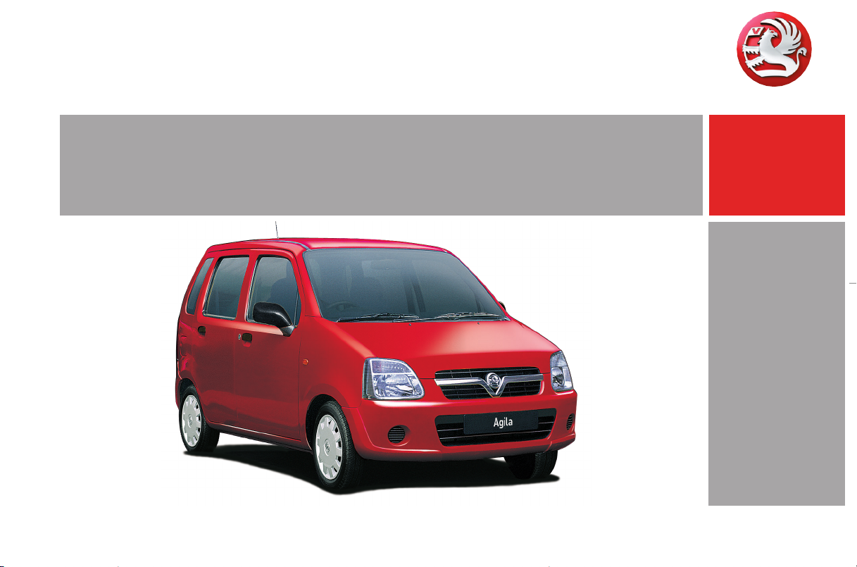
To unlock the v e hicle and
open the doors:
With key in l oc k
turn key towards front of
vehicle or
press bu tto nc on the remote
control 3,
pu ll door handle and open door
Rad io remote control3: Press button c
once - only driver’s door is unlocked; press
button c twice - all doors are unlocked.
To unlock t he doors from inside:
Pull up on lock button.
6 D oor lock s – page 30,
electronic immobilizer – page 2 9,
radio remote control 3 – page 31 ,
cen tr al locking sy ste m 3 – page 33,
anti-theft locking system 3 – page 33.
Page 8
3In Brie f
Pict ure no : 13471h.ti f
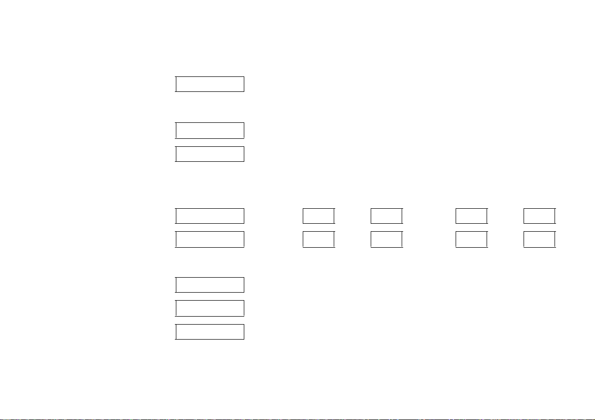
To unlock and open
the lugg age co m partment:
Turn the ke y anti clockwise to
horizon t al po s itio n and ba c k
to the vertical position
Alternatively press button c on the re mote
cont r ol 3 tw ice, pr ess button and open
tailgate
6 Mechanical unlocking – page 30,
radio remote control 3 – page 31 ,
central lo ck ing sy stem 3 – page 33,
tailgate – page 30.
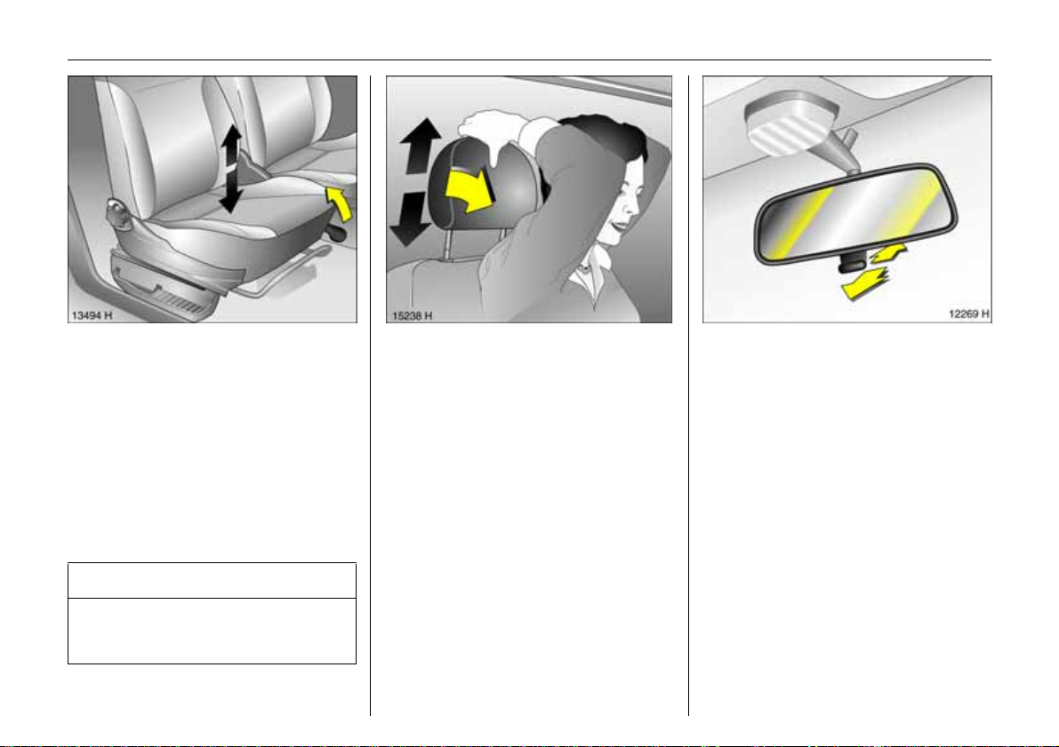
Pict ure no: 13457h. tif
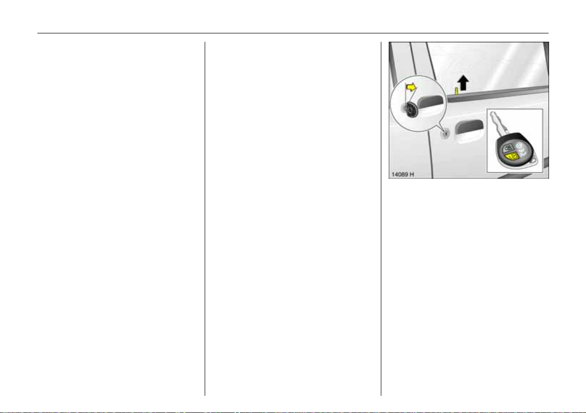
Front seat adjustment:
Pull handle,
s lid e seat,
r elease handle,
a udi bly en gage se at i n posit ion
Never adjust the seat while driving. It could
move in an uncontrolled manner when the
h andle is pulled.
6 Seat position – page 39,
storage tray under seat 3 – page 4 6.
9 Wa r n i n g
Do no t sit near er than 10 inches ( 25 cm)
from the steering wheel, to permit safe
airbag deploy ment.
Pic tur e no: 13458h.t if
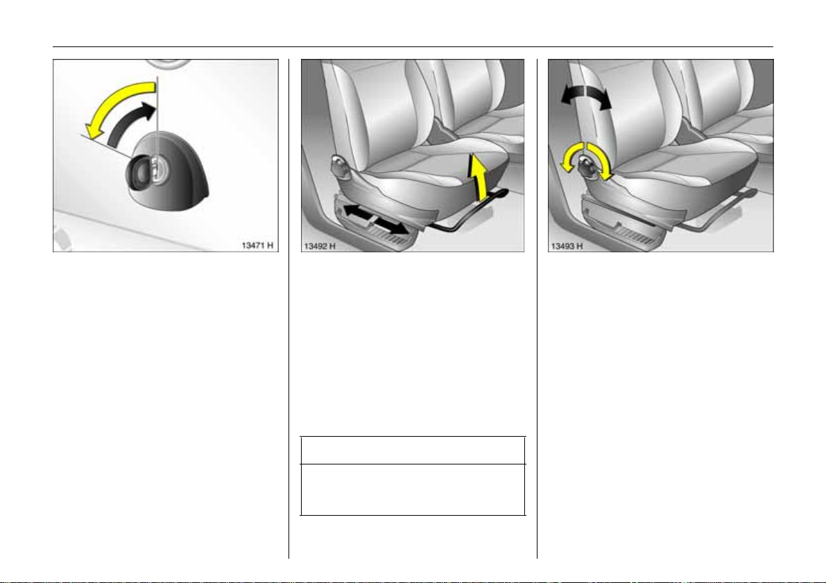
To adjust the f ront seat
backrest:
Turn the handw heel
Mov e seat b ackre st t o s uit seati ng position .
Do not lean on seat backr est whilst
adjus ting it.
6 Seat position – p age 39,
folding th e fr ont passenger seat – page 42.
Page 9
4In Brief
Pict ure no : 13459h.ti f
To adjust height 3
of front seat:
Pull lev er on side
Lift le v er an d relieve some weight f rom seat
to raise it or press down on seat with body
weight to low er it.
Never adjust the seat while driving. It could
move in an uncontrolled manner when the
handle is pulled.
6 Seat position – page 39.
9 War n ing
Do n ot sit nearer than 10 inches (25 cm)
fro m the steeri ng wheel, to pe rmi t safe
airbag deployment.
Pict ure no: 15137h. tif
To adjust the hei ght of
front seat head restraints:
Tilt forward to unlock, hold fir mly
and adjust height, release
6 adjusting
rear seat head restraints – page40,
h ead res traint position – page 39,
h ead res traint removal – page 39.
Pic tur e no: 12246h.t if
Adjusting interior mirror:
Swivel mirror h ousing
Swivel lever on underside of mirror housing
to reduce dazzle at night.
Page 10
5In Brie f
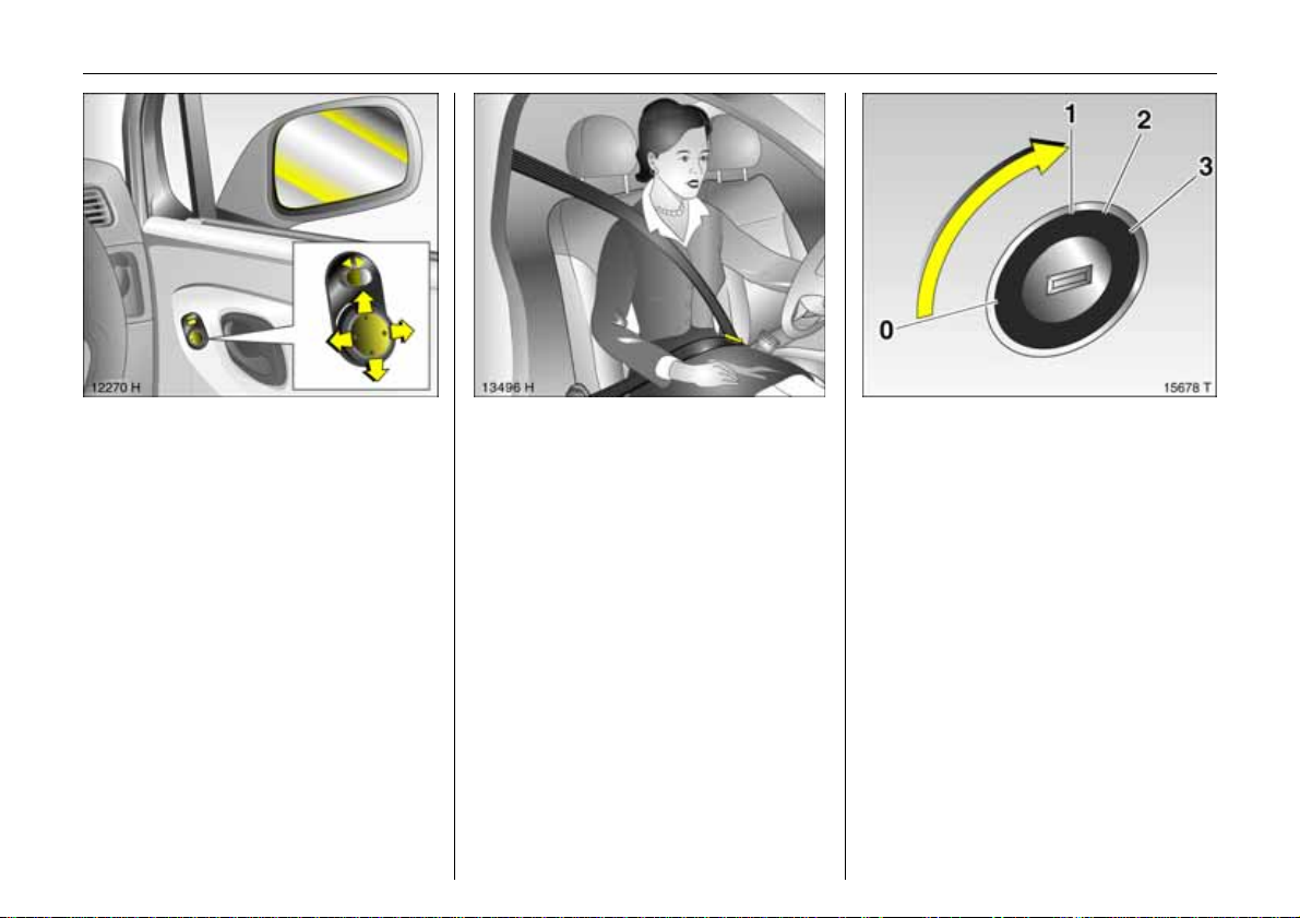
Pict ure no : 12247h.ti f
To adjust exterior mirrors:
Manuall y - pres s
edge of relevant
mirror;
Electrically 3 - using four-way
sw itc h in driver’s door
Four-way switch3: Move rocker switch to
the left or right - the four-way switch
adjust s the corresponding mirror.
The exterior mirrors can be retracted (e.g.
when parking in tight spaces) thro ugh
slig ht pressure on the mirror hous ing.
Reposition the mirrors be fore sta rting off.
6 Further information – page 65.
Pict ure no: 13461h. tif
Fitting se a t belt:
Draw seat belt s moothly f rom
inertia reel, guide ov er should er
and engage in buckle
The belt must not be twiste d at any point.
T he lap belt must lie snugly against the
body. The backrest must not be tilted back
too far (re comme nded tiltin g an gle
approx. 25 °).
T o release belt, press red but ton on belt
buckle.
6 Seat belts – pages 5 0, 52,
airbag systems 3 – page 5 6,
seat position – page 39.
Pic tur e no: 15678t.t if
Di s e n gagi n g ste e r ing c olum n
lock:
To release the lock,
move the st eering wheel sl ightly
and turn the key to position 1
Positions:
0 = Igni t ion off
1 = Steering released, ignition off
2 = Ignition on,
Starting – page 15,
electronic immobiliser – page 29 .
Remove key and lock steering wheel –
page 16.
Page 11
6In Brief
Page 12

7In Brie f
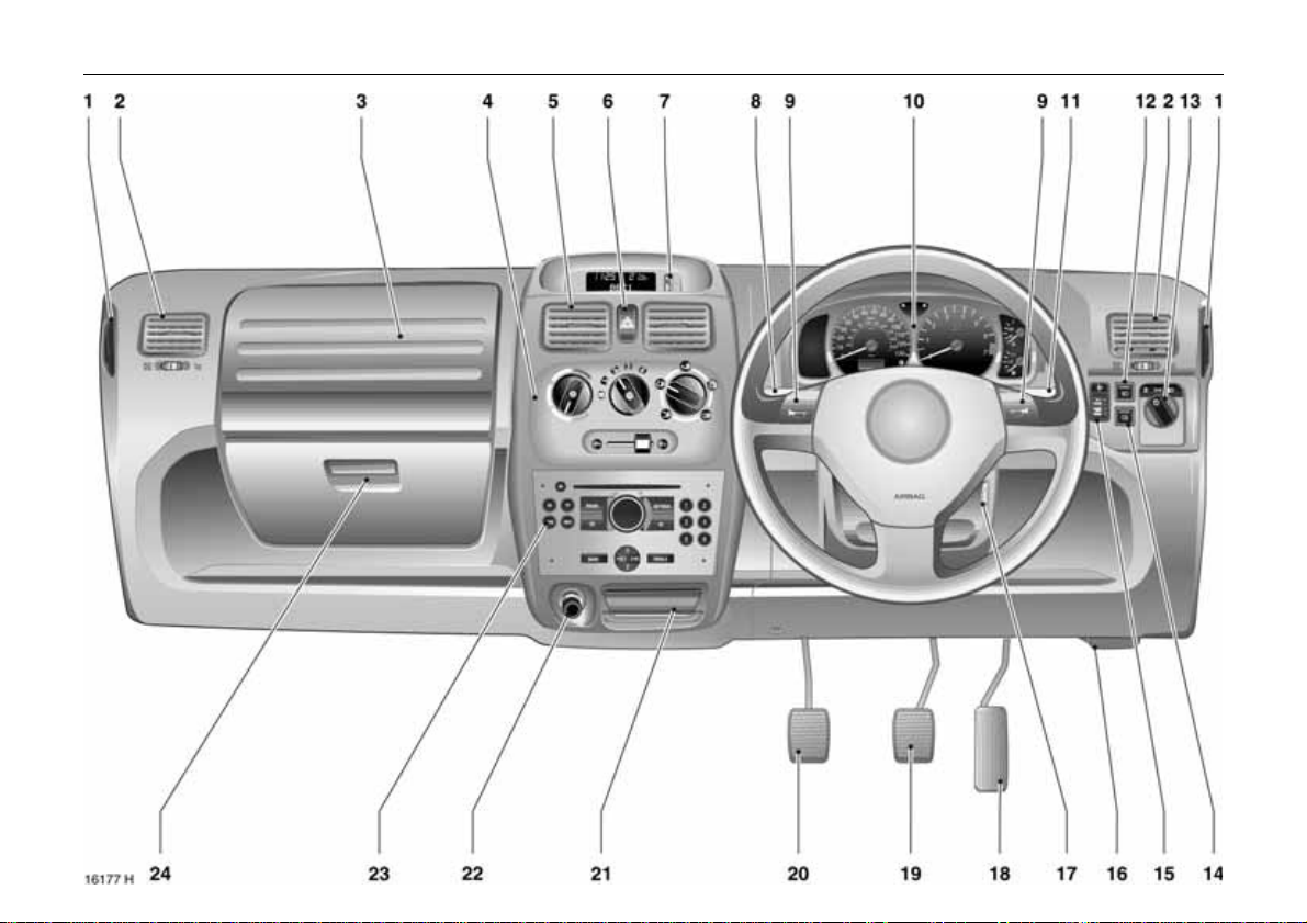
7
Page
1 Door window defroster vents ...........73
2 Side air vents .....................................73
3 Front passenger airbag 3 ................57
4 Heating and venti lation system,
air conditioning system 3 ...............72
5 Centre air vents .................................73
6 Hazard warning lights......................11
7 Display for time, date,
outside temperatures,
infotainment system 3 ......... ......... ..24
8 Turn signal, he adlight flash,
dipped beam, main beam ........ 10, 11
9 Horn ...................................................11
10 Instruments........................................18
11 Windscreen wiper,
windscreen washer system,
rear window washer system 3.........12
12 Fog lights3 .......................................67
13 L ight swi tch .. .... ......... ..... .... .... ..... 10, 6 6
14 Fog tail light ......................................67
15 Head light ra nge ad justment 3........67
16 Bonnet rel ease lever .........................37
17 Ignition switch
with steering column lock (h idden) ..5
18 Accelerator pedal .............................82
19 Brake pedal ......................................92
20 Clutch pedal .....................................83
.......................................................Page
21 Ashtray 3 ... ...................... ......... ....... 4 9
or storage compartme nt
22 Cigarette lighter 3............................ 49
23 In fot a in m e nt sy st em 3 ............. ....... 2 6
or storage compartme nt
24 Glove compartment with cover3 .47
Page 13

8In Brief
Control indicators
S Engin e oil level 3:
see pages 18, 132.
E PS Electronic power steering 3:
see page 18.
A Engine electronics,
immob ilizer,
fault
see pages 19, 29, 9 0.
Z Exhaust emission:
see pages 19, 89.
O Turn signal lights:
see page 19.
C Main beam:
see pages 10, 19, 6 6.
u Anti-lock brake system 3:
see page 94.
R Brake system:
see pages 20, 136.
p Alternator:
see page 20.
I Engine oil pressure:
see page 21.
Y Fuel level:
see pages 21, 23, 87.
v Airbag systems3,
be lt tens ione rs :
see pages 51, 60.
Lighting
Light switc h,
st alk positions:
see page 66,
7 Lights off,
8 Parking lights,
9 D ipped beam, main be am,
0 Courtesy light:
see page 68.
> Fog ligh ts 3:
see page 67.
r Fog tail l ight:
see page 67.
C Main beam:
see pages 10, 19, 66 .
O Turn signal lights:
see page 19.
? Headlight range adjustment 3:
see page 67.
¨ Hazard warning lights:
see page 11.
Page 14

9In Brie f
Climate control
x Air flow:
see page 75.
Air distribution:
see page 75,
K to foot well,
J to wind screen , front
d o or w in dow s an d
foot well,
V to w i n dsc r e e n a n d
front door wi nd ows,
M to h ead area above
adjustable air vents,
L to h ead area abo ve
adjustable air vents
an d to foot well.
Ü Heated rear window:
see page 74.
4 Air recirculation system:
see page 74.
5 Outside air intake:
see page 74.
n Air conditioning system 3:
see page 78.
Win d sc reen wip ers
Stalk positions:
see page 12,
§ Off,
$ Timed inte rval w ipe,
% Slow,
& Fast
Date, time, information dis play,
in f ot a in men t syst em
Tripl e infor matio n display 3:
see page 24,
Ö On butt on for date
and time
; Settin g buttons for date and time
Miscellaneous
e Central locking system
with remote control 3
lo cking – see page 33.
c Central locking system
with remote control 3
u nlocking – see page 33.
m Central locking switch 3:
see page 34.
j Horn,
see page 11.
Page 15
10 In Brief
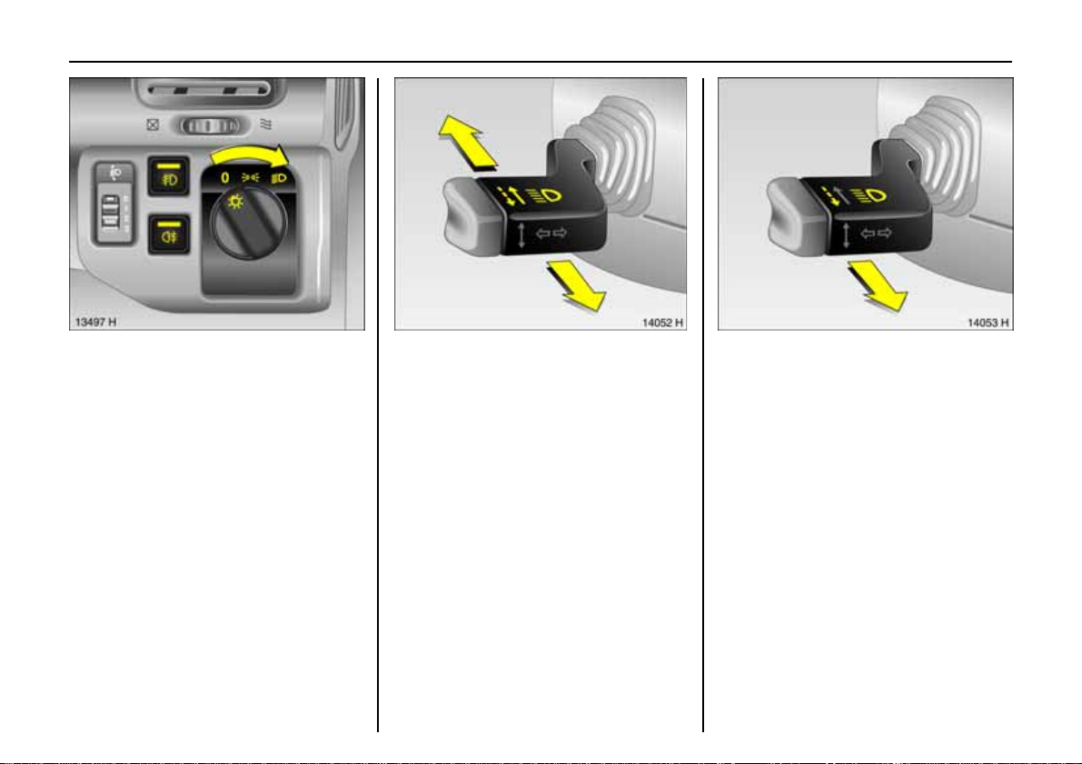
Pict ure no : 13462h.ti f
Lig ht switch:
7 =Off
8 = Parki ng lights
9 = Di ppe d be am or
main bea m
Pull0 =Courtesy light
Pres s > = Fog lights 3
Pres s r = Fog tail light
6Fur ther information – page 66,
head light warning device – page 15,
head lig ht range adju stment 3 – page67,
daytime running lig hts 3 – page66.
Pict ure no: 14052h. tif
Main and dipped
beam swi tc h:
Main be am = Push stalk
forward
D i pp e d beam = Pul l s t alk
toward steering
wheel
The blue control indicator C is illuminated
when main beam is on.
Pic tur e no: 14053h.t if
He adlight fla sh:
Pull stalk toward s steerin g wheel
Page 16
11In Brief
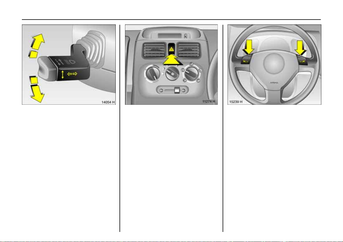
Pict ure no : 14054h.ti f
Operat ing t u r n s i gn al ligh t s :
Lev er in rest positio n
Ri ght tu r n = Upwar ds
Left turn = Downw ards
When the steering wheel is turned back, the
lever automatically returns to i ts original
position. This will not happen when making
a minor steering manoeuvre such as
changing lane.
When lane changing, move lever to
resistance point. When released, the lever
will spring back.
Picture no: 11130H. tif
Haza rd warning lights:
On = Press ¨
Off = Press ¨ ag ai n
When the button is pr esse d, its control
indicator flashes in time with the hazard
warnin g lig hts.
Pic tur e no: 15140h.t if
Ho r n o pe r ati on:
Press j
6 Airb ag systems 3 – page 56 .
Page 17
12 In Brief
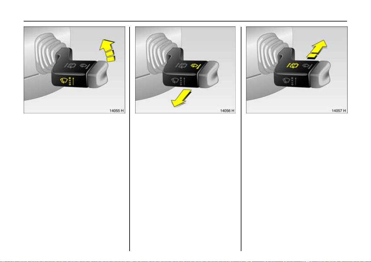
Pict ure no : 14055h.ti f
Wind screen wipers:
Move stalk up
§ = Off
$ = T i m e d int e r val wi pe
% = Slow
& = Fast
Pict ure no: 14056h. tif
Operating windscreen washer
system:
Pull stalk t owards steering whee l
The w iper s will swipe for a few s troke s .
6 Further information – page 137.
Pic tur e no: 14057h.t if
T o o per a t e re a r w i nd ow
wiperand washer systems:
Wiper on = Push stalk
forward
Wiper o ff = Pu ll sta lk
towards
steering wheel
Washe r = Push stalk
fo r w ar d and
hold
6 Further info rm atio n – page 1 37.
Page 18
13In Brief
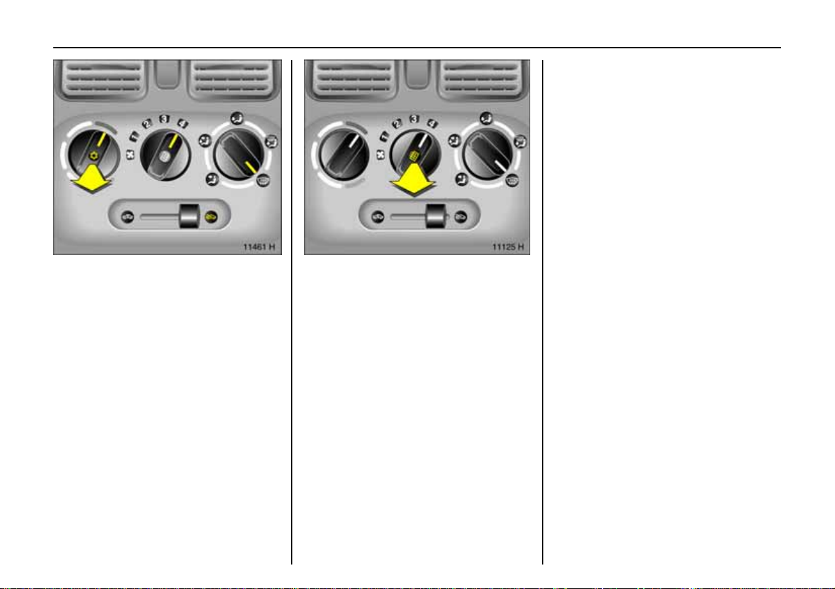
Pic tur e no: 11461H.tif
T o c lear misted or i c y windo ws:
Turn the rotary s witc hes fo r
temperature and
quantity of a ir clockw ise,
set air distribution to V
To switch onthe
air conditioning 3,
pul l t emper atu re switch n
Open side air vents as necessary and direct
them tow ards the doo r windows .
6 Climate contr ol – page 72,
air conditioning system 3 – page 78.
Picture no: 11125H. tif
Heated rear window:
On = Pull fan switch Ü
Off = Press fan switchÜ
Switch off as soon as rear vision is clear.
6 Further information – page 74.
Page 19
14 In Brief
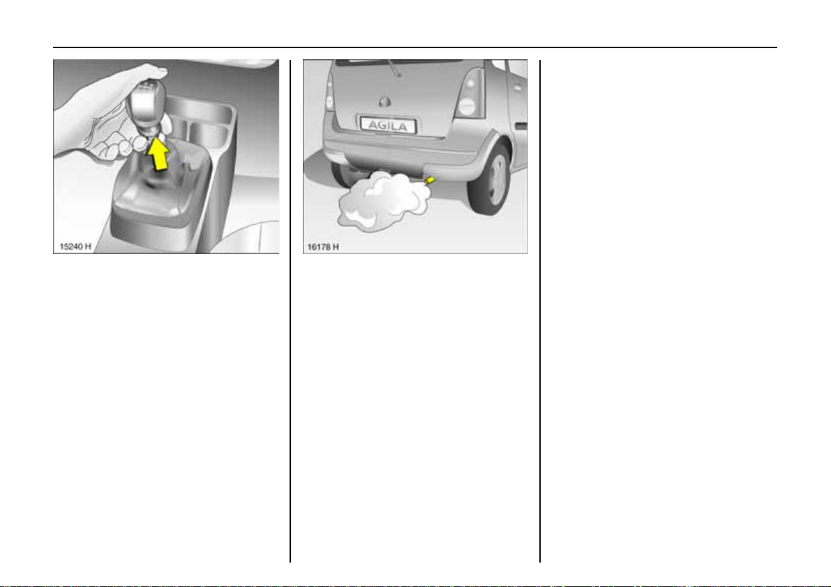
Pict ure no : 15141h.ti f
Man ual transmis sion
Engaging reverse gear on vehicles with
release ring on gear lever: with vehicle
stationary, 3 seconds after de press in g the
clutch pedal lift ring, move gear lever to the
left an d engage gear.
Engaging reverse gear on vehicles without
release ring on gear lever: with vehicle
stationary, 3 seconds after de press in g the
clutch pedal move gear lever to the righ t
and engage gear.
If the gear does n ot engage, set the lever in
ne utral, release th e clutch peda l and
depress again; then repeat gear selectio n.
Pict ure no: 16178h. tif
Exhaust gase s are poisonous
E xhaust ga ses contain carbo n monoxid e,
which is extremely poisonous but is
od ourless and colourles s.
Therefor e neve r inhale ex haust gases, and
n ever run the engine in an enclosed space.
A lso avoid driving with the luggage
com partment open. Otherwise exhaust
fumes could penetrate the vehi c le interior.
Befor e starting off, check:
z Tyre pressu re and con dition - se e
pages 98, 152.
z Engine oil level and fluid levels in engine
compartment – see pages 131 to 137.
z All windows, mirrors, exterior lig htin g
and number plates are free from dirt,
snow and ice and operational.
z Do not place any objects in front of the
rear window, on the in strument panel or
in the area in which the airbags inflate.
z Seats, seat belts and mirrors are
correctly adjusted.
z Check brakes.
Page 20
15In Brief
Warning buzzers
When the vehicle is park ed and the driver’s
door is op ened the warning buzzer will
sound if:
z the ignition key is in the ignition switch 3
z parking lights or dipped beam o n 3.
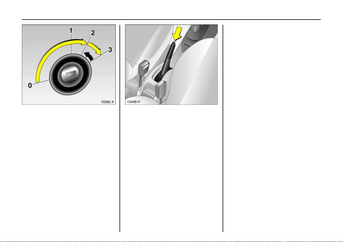
Picture no: 15582a. tif
To start the engine:
D e press c l u tch and bra ke pe dals,
do not accelerate,
petrol eng ine: key to 3;
release key once en gine i s
running
Before restarting or swit c hing off the
engine, turn key back to 0.
To switch on the ignition, only turn the key
to 2.
6 Electronic i mmobilizer – page 29, furt her
informatio n – page 106.
Pict ure no: 13463h. tif
R e leasin g th e ha nd brak e :
Raise lever slig htly ,
Pres s unlock button,
Lowe r lever fully
And now "Have a good journe y!"
Dr ive carefully, economically and with the
environment in mind. While driving, do not
do anythin g that could distract you.
Page 21
16 In Brief
Pict ure no : 15143h.ti f
Parki ng the vehicle :
Apply handbrake fi rmly,
eng in e off,
remove key,
lock steering wheel,
lock vehi cle
To lock, turn the key in th e lock toward the
rear of the vehic le or press button e on the
remote control. To activate the an ti -t heft
locking system 3, turn the key toward the
rear of the vehicle twice or press button e
on the remote control twice.
6 Further information – pages 29, 82,
radio remote control 3 – page 31,
central lo ck ing sy stem 3 – page 33 ,
vehicle decommissioning – page 1 39.
Whe n park i n g:
z Always apply hand brake firmly. On
slopes apply the hand brake as firmly as
pos sible.
z Engage first gear or revers e.
z Closing w indows a nd sun roof 3.
z Turn steering wheel until lock is felt to
eng age (anti-theft prote ction).
z Engine cooling fan may run on after the
engine has been switched off.
z Do not park ve hicle on e asil y ignitable
surfaces as the hot exha ust sys tem
temperature s could ca use the surface to
ignite.
Picture no: 15218H.Tif
Ser vic e w o rk,
Maintenance
We recommend that you entrust a ll work to
your Vauxhall Authorised Repairer, who
can provide you with reliable s ervice and
correctl y perform all work according to
factory instructions.
6 If you have a problem– page 128,
service interval display – page 130.
Page 22
17In Brief
Genuine Vauxhall Pa rts and
Accessories
We r eco mmend that you use "Ge nuine
Vauxhall Part s and Accessor ies" and
conversion parts released expressly for
your vehicle type. Th ese parts ha ve
undergone special tests to esta b l ish their
reliability, safety and specific suitability for
Vauxhall vehicles. Despite continuous
market monit orin g, we cannot assess or
guaran tee t hese attribu tes for other
products, even if they have been granted
approval by the relevant authorities or in
some other form.
"G enuine Vauxhall Parts and Accessori es"
and con versio n parts approved by
V auxhall can be obtai ned fr om your
V auxhall Authorised Repairer, who can
also provide expert Vauxhall advice on
permitted technical changes and ensure
correct installation.
9 Wa r n i n g
Carry out regularly the checks
recommended in the individual sections
of this Owner’s Manua l.
Ensure that your vehicle is serviced at the
service intervals specif ied in the Service
Booklet. We recommend that you entrust
this wor k to your Vauxhall Authorised
Repairer.
Have faults remedied without delay!
Consult a workshop. We recommend your
Vauxhall Authorised Repairer. If
ne cessary, interrupt your journey.
6 Main te n ance – page 130.
That was a brief lo ok
at the most important
information for your firs t d rive in
your Agila.
T h e remain ing ch apt er s
of the Owner’s M a nual
co ntain im p or t ant info rm a t ion on
opera tio n,
safety
and maintenanc e
as well as a
com plete index.
Page 23
18 In struments
Instruments
Control indicators ................................ 18
Instrument display............................... 22
Informat ion display 3 ......................... 24
Radio reception 3................................ 26
In fotainme n t system 3........................ 26
Mobile telephones and radio
equipment 3...................................... 26
Pict ure no: 15216h. tif
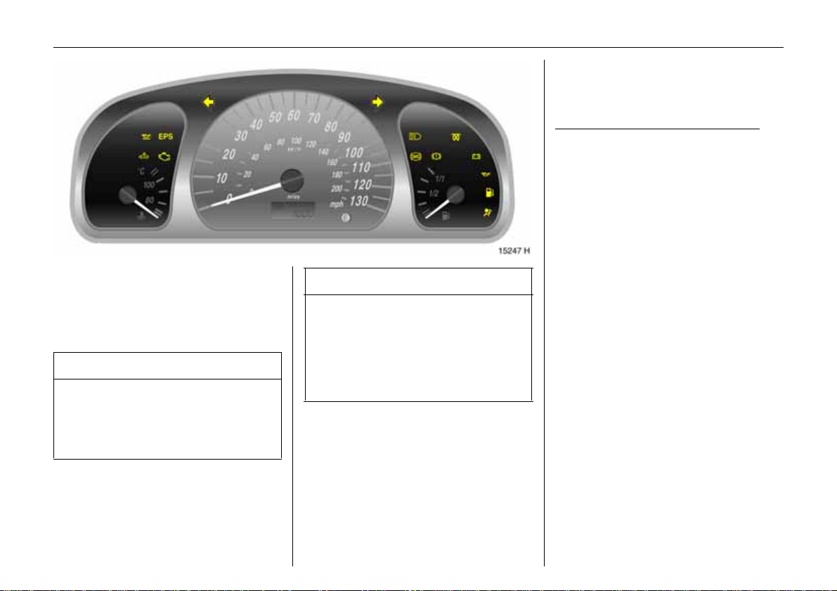
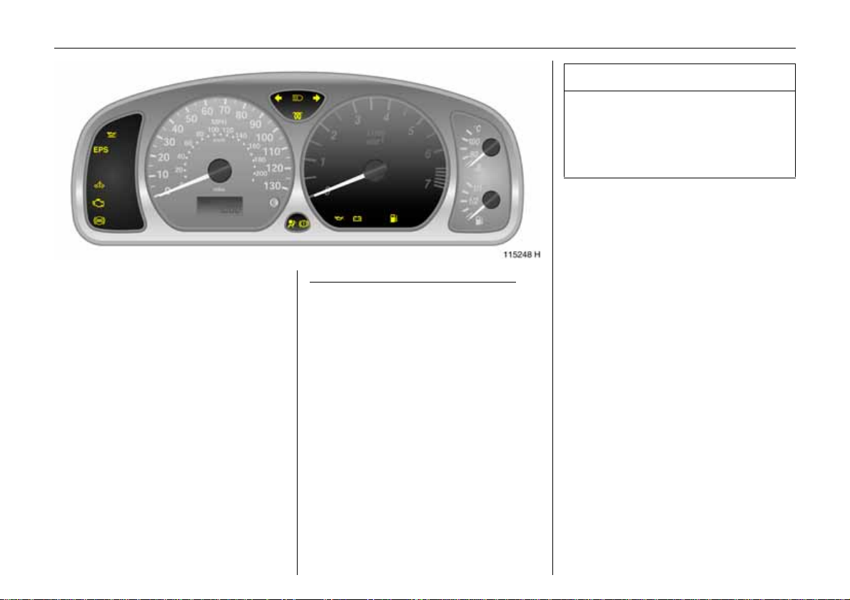
Control indicators
T he control indicato rs described here are
n ot present in all vehicles. The description
applies to all instrument versions.
S
Engin e oil level 3
T he en gine oil level is checked
automat ically.
Illuminated: Engine oil level too low. Check
o il level and top up as necessary. See
page 132.
1)
EPS
Electric power steering 3
The control indicator illuminates for a few
seconds when the ignition is swit ched on.
Illumination while driving indicates a fault.
Driving may be contin ued. More force is
required for steering. Consult a wor kshop.
We rec o mmend your Vauxhall Author ised
Repairer.
1)
EPS = Electronic Power Steering.
Picture no:
Page 24

A
Pict ure no : 15217h.ti f
E ng ine electr o ni cs, imm obiliz er
The control indicator illuminates for a few
seconds when the ignition is swit ched on.
Illuminates when the engine is running
Fault in the engine electronics system. The
electronics system switc hes to limp-ho me
mod e. Fuel consumpti o n may increa se and
the dr iveability of the vehicle may be
impaired – see page 90. Consult a
workshop. We recom mend your Vauxha ll
Authorised Repairer.
If it flashes when the ignition is on:
Fault in the electronic immobilizer sys tem;
the engine cannot be started – see
page 29.
Z
Picture no:
Exhaust emission
Illuminates when the ign ition is switched
on. Goes off shortly after the engin e starts.
Illuminates when the eng ine is running
Fault in emission control system. The
permitted emission limits may be
exceeded. Consult a workshop. We
recommend your Vauxhall Authorised
Repairer.
If it flashes wh en the engine is runn ing:
Fault that can lead to destruction of the
catalytic converter is indicated – see
page 89. C onsult a workshop immediately.
W e recommend that you consult your
Vauxhall Authorise Repair er.
19Instruments
O
Turn signal lights
When the turn signal is activated, the
corresponding con trol indica tor flashes.
Rapid flash: A turn signal bulb is faulty.
Bulb replacement – see page 122.
Both control indicators flash when the
hazard warn ing lights are activated.
C
Main beam
The control indicator is illuminated when
ma in beam is on a nd during headlight
flash – see page 10.
u
Anti-lock brake system (ABS) 3
see page 94.
Page 25
20 In struments
p
Alternator
Illuminates when the ignition is switched
on. Goes off shortly after the engine starts.
Illuminates when the engin e is run ning
Stop the veh icle and swi tch of f the eng ine.
The battery is not being charged. Engine
cooling may be interrupted. Contact a
workshop. We recommend your Vauxhall
Authorised Repa irer.
R
Pict ure no : 15216h.ti f
B ra k e sy s tem
The control indicator illuminates when the
ignition is switched on if the hand brake is
applied or if the brake fluid level is too low.
Further information – see page 136.
9 War n ing
Illuminated w hen the hand brake is not
applied: Stop the vehicle; interrupt your
journe y immediately. Consult a
workshop. We recomme nd your Vauxha ll
Authorised Repairer.
Picture no:
9 Wa r n i n g
Illuminated together with th e control
indicator for the Anti-lock Brake
System u: The braking force on the rear
wheels is not being regulated. The vehicle
may swerve during braking. Consult a
workshop. We recommend your Va ux ha ll
Authorised Repairer.
Page 26
I
Pict ure no : 15217h.ti f
Engine oil pressure
Illuminates when the ignition is switched
on. Goes off sho rtl y after the engine starts.
Illuminates when the eng ine is running
Picture no:
Engine lubricatio n may be interrupted. This
may result in damage to the engine and/or
lo cking of the drive wheels:
1.Move out of t he flow of traffic as quickly
as possible without impeding other
vehicles.
2. De press clutch.
3.Put the tra nsmission in neutral
4.Switch off ignition.
21Instruments
9 Wa r n ing
When the engine is o ff, consid erab ly
more force is needed to brake and steer.
Do not r emov e ke y until ve hicl e has c ome
to a standstill, otherwise the steering
column lock could engage unexpectedly.
Contact a workshop. We recommend that
you consult your Vauxhall Authorise d
Repairer.
Y
Fuel level3
Illuminated: Low fuel level. Fuel gauge in
reserve area.
If it f lashes: Fuel reserve used up, fill up
immediately.
Never let the tank run dry!
Erratic fuel supply can cause catalytic
converter to overheat – see page 88.
v
Airbag systems3 ,
be lt tension ers
see pages 51, 57.
Page 27
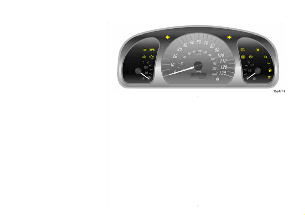
22 In struments
Pict ure no : 12941h.ti f
Instrument display
Tachometer 3
Indicate s en gine s peed.
Warn in g zone: m aximum permissible
engine sp eed exceeded ; danger to engine.
Speedometer
Indicates the vehicle speed.
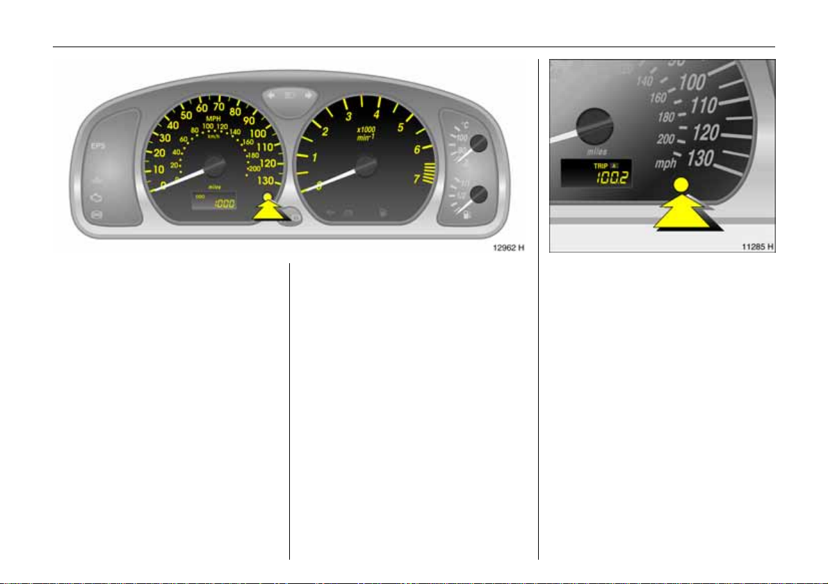
Odomet er
Switchable between overall odometer and
two tr ip odometers A or B.
Overall odometer
With ignition on, display of total miles
driven – "ODO"1) appears on the display.
1)
ODO = Odometer.
1)
Trip odometer
Picture no: 11141H.tif
Switchable from overall odom eter (ODO)
to trip odometer A (TRIP A) or trip
odomete rB (TRIP B). Press the reset knob
briefly to switch between the three optio ns.
Res et trip odometer A or B by press ing and
holding down the reset knob for
approx. 2 secon ds.
Service interval display, see page 130.
Page 28
For physical reasons, the engine
temperature gauge shows the coolant
temperature only if the coolant level is
adequate.
During operation the system is pressurised.
The temp erature may therefore rise briefly
to over 100 °C.
23Instruments
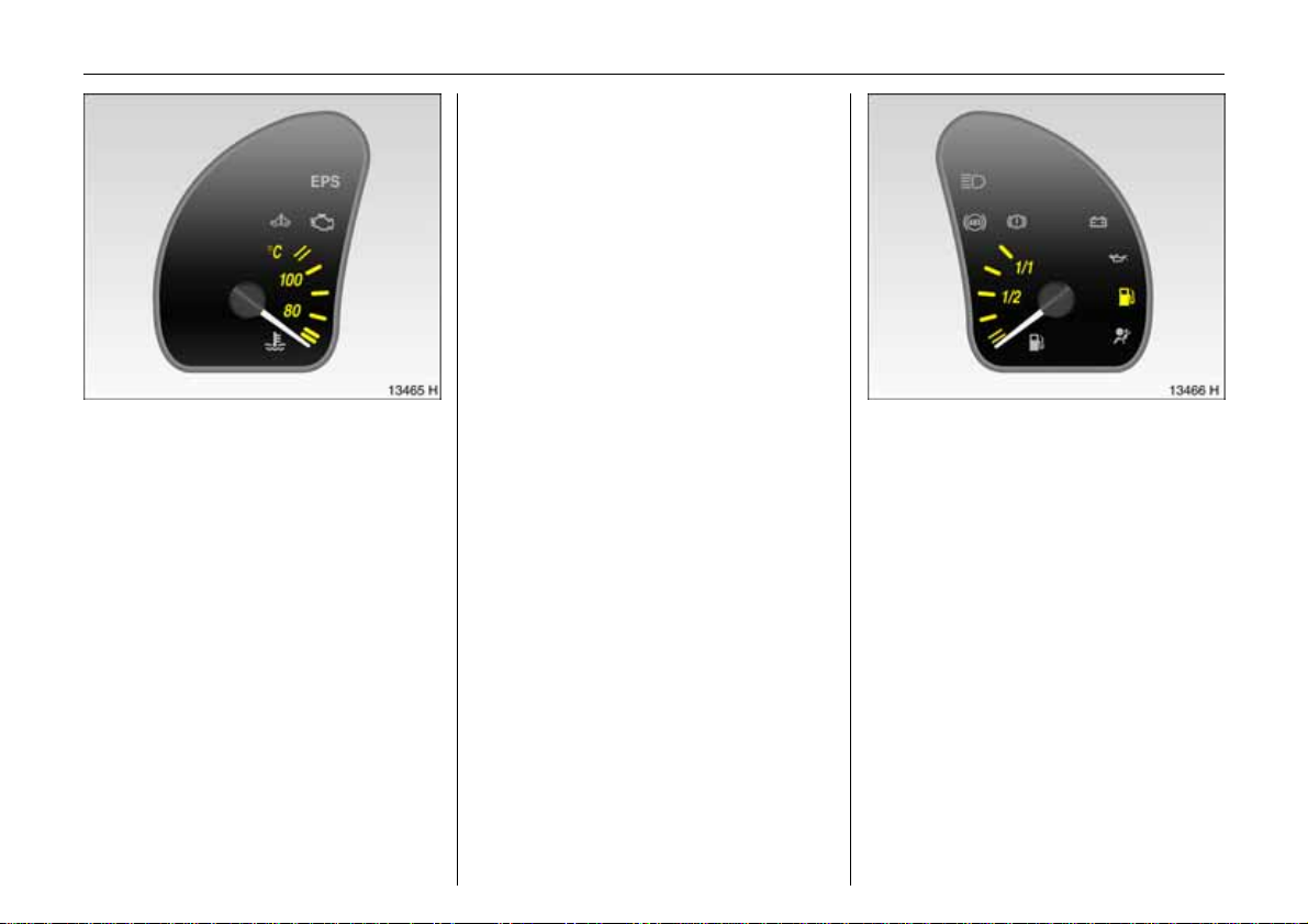
Coolant temperature display
Pict ure no : 13465h.ti f
Pointer in low
zone = Engi ne operat ing
temperature not ye t
reache d
Pointer between
the zo nes = Normal operating
temperature
Pointer in upper
(warning ) zone = Temperature too
high:
Stop vehicle and
s w i t ch off engine.
Danger to engine,
check coolant level
immediately – s ee
page 134.
Fuel gauge
Pic tur e no: 13466h.t if
Pointer in red
zone or Y
illuminated = Reserve area
Pointer in red
warning zone
or Y flashing = Fill up immediately –
see page87.
Never let the tank run dry!
Because of the fuel remaining in the tank,
the amount of fue l required to fill the tank
may be less than the spe cified tank
capacity.
Page 29
24 In struments
12:01 17,0°C
FM 3 90,6MHz
REG AS RDS TP
Setting date and time
Date and time can eithe r be set manually
or corrected automatically with an RDS
time signal1)3.
Some RDS tran smitters do n ot send correct
time signals. If the incorrect time is
displayed often, deactiva te auto matic
time synchronisation3 and set the time
manually.
The automatic setting is indicated by Ö in
th e display.
8:56 5,5°C
07.04.2004
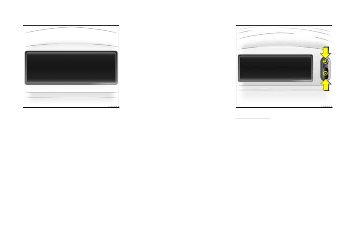
Pict ure no: 17913s.t if
Information display 3
Tripl e information display
Display of time, outside tempe rat ure and
date/infotainment system i f it is swi tched
on.
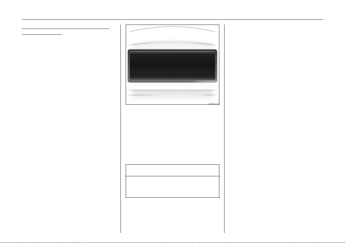
When the ignition is off, the time, date and
outside temperature can be made to
appear for approx. 15 seconds by briefly
pressing one of the two buttons on the
right-ha nd side of the display.
1)
RDS = Radio Data S ys tem.
Manual sett ing
Picture no: 17914 s.tif
Infotainment system off. Pre ss Ö an d ;
next to the di splay as follows:
Pres s Ö for approx. 2 seconds:
Day flashes
;:Set day
Ö:Month flashes
;:Set month
Ö:Year flashes
;:Set year
Ö:Hours flash
;: Set ho urs
Ö: Minutes flash
;: Set minutes
Ö: Clock is started.
Page 30
25Instruments
Deactivating and activating automatic
setting functi on 3
Infotainment system off. Press Ö and ;
next to the display as f ollows:
hold down Ö for approx. 2 sec., clock
display is now in setting mode,
Pres s Ö twice ( until year flashes).
Pres s Ö and hold down for approx.
3seconds until} flashes in d isplay and
text "RDS TIME" appears (years flash
during this time),
Pres s ;; display of:
RDS TIME 0 = Off.
Pres s ;; display of:
RDS TIME 1 = On
Pres s Ö three times.
Fault display
An F in the display indicates a fault. Have
th e cause remedi ed. We recommend that
you consult your Vauxhall Authorise d
Repairer.
:
8:56 -5,5°C
07.04.2004
Pic tur e no: 17913s.tif
Outside temperature
A fall in temperature is indicated
immediately and a rise in temperature
aft er a time delay.
If ou tside temperature drops below 3 °C,
th e symbol : appears in the inf ormation
display as a warning for icy road
conditions. When tem perature increases to
at least 5 °C, the : symbol go es out.
9 Wa r n i n g
Caution: The road surface may already
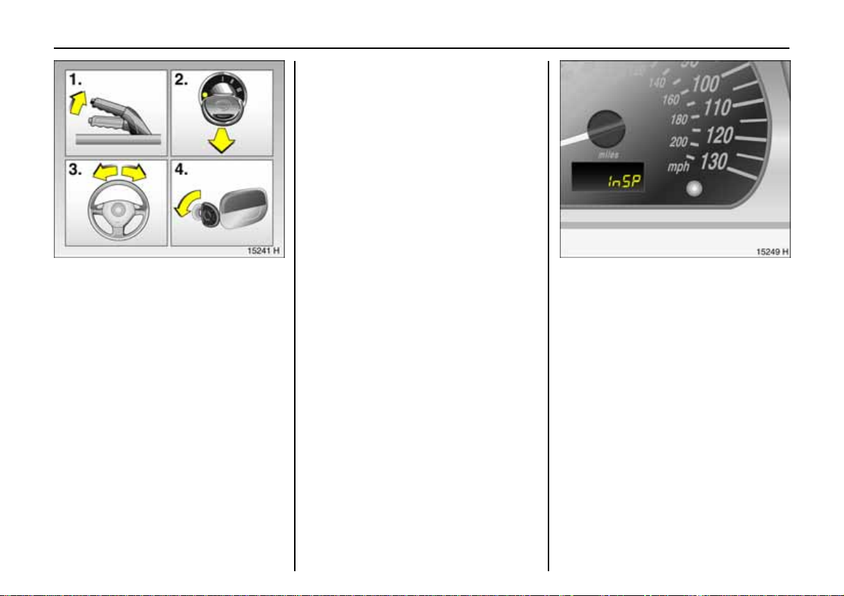
be icy even though the display indicates
a few degrees above 0 °C.
Page 31

26 In struments
Ra di o rece p t ion 3
Ca r radio rece ption diffe rs fro m do mestic
radio reception:
As the v eh icle antenna is relat ively near the
grou nd, th e broa dcas tin g com panies
cannot guarantee the same quality of
reception as obtained with a domestic
radio using an overhead antenna.
z Changes in distance from the
transmitter,
z multi-pa th re cep tion due to refle ction
and
z shadowing
may cause hissing, noise, distortion or loss
of reception altogether.
In fotainmen t system 3
The i nfotainment system i s operated as
described in the operating instructions
supplied.
Mobi le telephones and radi o
equip ment3
The Vauxhall in stallation in str uctio ns and
the op erating guide lin es provided by the
telephone manufactu rer must be obse rved
when fitting and operating a mobile
telephone. Fail ure to do so could i nvalidate
th e veh i c le’ s op era ti n g perm i t (EU Di rec ti ve
95/54/EG).
Prerequisites for fault-free operation:
z Professionally installed exterior antenna
to obtain th e maximum range possible
z Maximum transmission power 10 Watt,
z Installation of the telephone in a suitable
spot (see information on page 6 1).
Page 32

27Instruments
Obtain advice on predeterm ined
installation locations for the external
antenna and equipment holder and ways
of usin g devic es wit h transmis sion power of
more than 10 Watts. We recommen d that
you consul t your Vauxhall Aut ho rised
Repair er, who will have brackets an d
various installatio n kits available as
accessories and will install them in
accordance with regu lations.
For reasons of safety, we recommend that
you do not us e the phone while driving.
E ven use of a hands-free set c an be a
distraction while driving. Be sur e to observe
any country-specific regulations.
9 Wa r n i n g
When used in the vehicle interior, mobile
telephones and radio equipment ( CB)
with integrated antenna may cause
malfunctions in the vehicle electronic s.
Mobile telephones and radio equipment
(CB) should only be used with an antenna
fitted on the vehicle exterior.
Page 33

28 Keys, Doors, Bonnet
Keys, Doors,
Bonnet
Electronic immobilizer ......................... 29
Me chanical unlocking or lock ing of
individual doors................................. 30
Radio remote control 3....................... 31
Central locking with vehicle key 3,
central locking with remote
control 3 ............................................ 33
Child safety locks ................................. 37
Bonnet .................................................. 37
Replacement keys
The key is a constituent of the elec tronic
immobiliser. Ordering keys from a Vauxhall
A uthorised Repairer guarantees problemfree operation of the electronic
immobiliser.
Keep the spare k ey in a safe spot.
Locks – see page 143.
Loc k cylinders
Designed to free-wheel if they are
forcefully rotate d without the c orrect key or
if the correct key is not fully inserted.
To reset, turn cylinder with the correct key
u ntil its slot is ver tical, remove key and then
re-insert it. If the cylinder still free-wheels,
tu rn the key through 180 ° and repeat
op eration.
Car Pass
The Car Pass contains all of the vehicle’s
data and should therefore not be kept in
the veh icle.
H av e y o ur Ca r P a s s o n ha n d w h en
consulting a Vauxhall Authorised Re pairer.
Page 34

29Key s, Doors , Bonnet
If the control indicator A illumin ates after
the engine has been started, there is a fault
in the engine electronics – see pag e 90.
Note
The immobilizer does not lock the doors.
After leaving th e vehicle, therefore, always
lock it – see page 33.
Pict ure no : 15761t.t if
Electronic immo biliz er
The s yst em c hec ks whet h er t he vehic le may
be started using the key that has been
inserted. If the key is "authorised", the
vehicle can be started. This check is carried
out via a transponder housed in the key.
The electronic immobiliser is automatically
activated when the key is removed from
the ignition switch.
Control indicator A for immo bilizer
Pict ure no: 12943h. tif
Con trol ind ica tor A illuminates briefly
when the ignition is switched on.
If the control indicator flashes when the
ign ition is on, there is a fault in the system;
the engine canno t be started. Swi tch off
th e ignition an d then repeat the s ta rt
attempt.
If control indicator A continues to flash,
try to start the engine using the spare key
and consul t a workshop. We recom me nd
your Vau xhall Auth orised Repair er.
Page 35

30 Keys, Doors, Bonnet
Pict ure no : 18155h.ti f
Me chanical unlocking or locking
of individual doors
(versions without radio remote control 3
and central locking system 3)
Front doors
To unlock:
Turn key in lock towards front of vehicle as
far as it will go. Return key to the vertical
position and r emove. Pul l door handle.
To lock:
With door closed, turn key towards re ar of
vehicle as far as it will go. Turn key back to
vertical position and remove.
Operating from the inside
Pull or press the interior lock b utton.
Tailgate
Pict ure no: 13506h. tif
To un l o c k :
Turn the key to the left as far as the stop,
tu rn back to the ve rtic a l position and
withdra w.
T he lock is released by pressing the button.
To l oc k:
Turn the key to the right as far as the stop,
tu rn back to the ve rtic a l position and
withdra w.
Open luggage compartment
Pic tur e no: 13746h.t if
There are two handles on the inside of the
tailgate to aid in closing.
Page 36

Note
z Fitti ng of accessories on the tailgate will
increase its we ig ht. If it be comes too
h eavy, it will then not stay open.
z T he number plate can only be clearly
seen if the tailgate is closed. It is
therefore not permitted to drive with the
ta ilg ate o pe n.
9 War n ing
Do not drive with the luggage
comp art me nt open, e.g. when
transporting bulky objects, sinc e toxic
e xhaust ga s coul d penetr ate the i nterior.
Pict ure no: 13468h. tif
Ra di o remote control3
T he radio remote control is integrated in
th e key.
Used to oper ate:
z central lock ing sy stem,
z mechanical anti-theft locking system 3.
The radio remote c ontrol has a range of
approx. 3 metres. This r ange can be
affected by outside influences. Aim the
remote control at the vehicle to operate.
31Key s, Doors , Bonnet
Pic tur e no: 13469h.t if
Handle radio remote control with care,
protect from moisture and high
temperatures and avoid unnecessary
operation.
The hazard warning lights come on to
indicate that the remote control is
ope r ational.
Central locking
with radio remote control 3,
see page 33.
Mechanical anti-theft locking system
with radio remote control 3
see page 33.
Page 37

32 Keys, Doors, Bonnet
Fault
If the central locking system cannot be
operated wit h the radio remo te contro l, it
may be due to the following:
z The range o f the radio remote control
has been exceed ed.
z T he ignition key is in the ignition lock.
z The doors are not closed properly.
z Remote control battery voltage is too
low. Battery replacement - see next
column .
z Interference from higher-power radio
waves f r om other sources.
To eliminate the cause of the fault, contact
your Vauxhall Authorised Repairer.
Manual unlocking and locking with the
veh ic le ke y - see page 30.
Remote control b attery replacement
Pict ure no: 13470h. tif
Replace the battery as soon as the range
of the radio remote control begins to
shrink.
Remove s crew on the underside of th e
re mote control key with a s crewdriver and
r emove cover.
T he trans ponder for the immobiliser is
lo cated in the key. Ensure that it is not
damaged or released.
Detach the remote control unit from the
key sect ion by pressing in the buttons.
A pply screwdriver and open remo te control
on both sides by making a slight turning
movement. See figure above.
Open up re mote contro l. Replace battery
Picture no:
(battery type - see page 154). Note
installation positio n of battery (positive
te rm ina l po int s down ).
Close remote cont rol and engage audibly.
Insert remote control unit in key se ction.
Close the cover and screw in place.
Make sure that y ou dispose of old batterie s
in accordance with environmental
protection regulations.
Page 38

33Key s, Doors , Bonnet
Pict ure no : 15144h.ti f
Cen tra l locking w ith
vehicle key 3,
centr al lock ing w ith
remote contr ol 3
For doors an d lu gga ge c ompartment.
To lock:
Turn key in front door lock toward rear of
vehicle, turn key back to vertical position
and remove.
– or –
Pres s button e on radio re mote control 3
– or fr om the inside –
With doors closed, pr ess button m on
driver’s door arm rest/pull. See next page,
fi gure 12273H.
Lockin g w ith mechanical
Pict ure no: 15146h. tif
anti-theft locking system 3
All doors mus t be close d. After l ocking, turn
the key in one of th e front door locks
towards the rear o f the vehicle again, t urn
i t b a c k to the h o r iz o n t a l p os i t i o n and
remo ve.
– or –
n o more than 2 seconds after locking, press
button e on the rem ote control 3 again.
Int erior lock buttons on all doors are
blocked from opening.
9 Wa r n i n g
Do not use the system if there are people
in the vehicle! The doors can only be
unlocked from the inside if the ignit ion
is on.
To unlock:
Pic tur e no: 15145h.t if
To unlock only t he driver’s door:
Turn key in driver’s door lock towards front
of vehicle once, then move back to vertical
position and remove.
– or –
Press but to n c on radio remote control 3
once.
– or –
Press but to n m on driver’s door arm rest/
pull. See next page, figure 12273 H.
Page 39

34 Keys, Doors, Bonnet
To unlock entire vehic le:
Turn key in front door lock toward fron t of
vehicle twice, turn key back to vertical
position and remove.
– or –
Pres s button c on radio remote control 3
again within 5 seconds
– or –
Pres s button m on driver’s door arm rest/
pull. See figure 12 273H.
If th e mechanical anti-th eft lock ing
system 3 is engaged, the doors cann ot be
unlock ed us ing butto n m on the driver’s
door arm rest/pull.
Note
z To prevent the driver from being
inadvertently locked out, the bu tton on
the driver’s door cannot be depressed
wh en t h e do or i s o pe n .
z The lock button will not sprin g up if the
door h an dle is raised wh en the door is
being closed.
z 30 seconds after unlocking using the
radio remote contro l 3, the doors lock
again automatically if n o door is
opened.
Pict ure no: 12250h. tif
Central locking switch for
locking and unlock ing the doors from
inside the vehicle
Press button m on driver’s door handle: all
doors are l ocked or unloc ked.
If the mechanical anti-theft locking
system 3 is engage d, the doors cannot be
u nlocked with this button.
Page 40

35Key s, Doors , Bonnet
z If the driver’ s door is open or t he ignition
is on, unl ocking and locking wit h the
ra d i o r e m o t e co n t ro l 3 is not possible.
z Unlocking is only possible with the key if
the anti-theft locking system is switched
o n, so keep the spare key available in a
safe place!
Central locking 3 the luggage
compartment
T he luggage compartment is locked and
u nlocked via the central locking system.
T he central locking system and anti-theft
lo cking system 3 for the doors cannot b e
o perated via the tailgate lock.
Page 41

36 Keys, Doors, Bonnet
Unlocking the tailgate when
Pict ure no : 13471h.ti f
the doors are locked with cent ral loc king
system
Turn the ke y anti-clockwise from the
vertical position as far as it will go. The key
spring s back to the centre position. The
tailgate is then unlocked and can be
open ed by p ressi ng the button .
After closing the tailgate, turn the key
Pict ure no: 13472h. tif
clo ckwise as far as it will go. The key
sp ri ngs back to the ce ntre position a nd the
tailgate is locked. Remove the key.
The key can only be removed when in the
vertical position.
Open the luggage compartment
Pic tur e no: 13746h.t if
There are two handles on the inside of the
tailgate to aid in closing.
Page 42

Note
z Fitti ng of accessories on the tailgate will
increase its we ig ht. If it be comes too
h eavy, it will then not stay open.
z T he number plate can only be clearly
seen if the tailgate is closed. It is
therefore not permitted to drive with the
ta ilg ate o pe n.
9 War n ing
Do not drive with the luggage
comp art me nt open, e.g. when
transporting bulky objects, sinc e toxic
e xhaust ga s coul d penetr ate the i nterior.
Picture no: 11155H. tif
Child safety locks
9 Wa r n i n g
Use the child safety lock whenever
children are occupying t he rear seats.
Disregard may lead to injuries or
endanger life. Vehicle passengers should
be informed accordingly.
Push the latch on rear door lock s d ow n:
door cannot be opened from the inside.
37Key s, Doors , Bonnet
Picture no: 11165H.tif
Bonnet
To open th e bonnet, pull the release lever,
located on the driver’ s side below the
instrument panel. The bonnet will then be
unlocked and will partially open. Return
release lever to its original position.
Page 43

38 Keys, Doors, Bonnet
The safety catch is located above the
Pict ure no : 16179h.ti f
radiator grille at the centre of the bonnet.
Open the bonnet by moving the catch to
the left and lifting the bonnet.
Any d irt or snow on the bonnet can slide
down towards the windscreen when the
bonnet is opened and block the air intake –
see page 80.
T o hold th e bon n et op en, in se rt th e su pp ort
Picture no: 11167H. tif
rod located on the right-hand s i d e of the
v ehicle (as viewed in the direc tion of travel)
in the slot on the under side of bonnet.
Before closing bonnet, press support rod
firmly into its retainer. Lower the bonnet
gradually and then allow it to fall into the
lo ck under its own weight.
Check that the bonnet is locked in position
by pulling at its front edge. If it is not
engaged, repeat the procedure.
Page 44

Se ats, Interior
39Seats, Interior
Lug gage compartment enlargement 41
La shing eyes3 .................................... 42
Notes on loading ................................. 42
Lug gage compartment cover 3......... 43
Safety net 3 ......................................... 43
Storage options in the vehicle int erior 45
Notes on loading the vehicle.............. 48
Sun visors.............................................. 48
Cigarette lig hter 3 ............................... 49
Accessory socket ................................. 49
Ashtray 3 ............................................. 49
Pict ure no: 13473h. tif
Seat pos i t ion
Ad ju st driver’s seat such that with the
driver sitt ing upright the steering wheel is
h eld in the area of its upper spokes with the
driver’s arms slightly bent .
P ush passenger seat as far back as
possible.
The seat backre sts must not be tilted too
far back (recomme nded tilting angle
approx. 25 °).
9 Wa r n i n g
Do no t sit near er than 10 inches ( 25 cm)
from the steering wheel, to permit safe
airbag deploy ment.
Failure to observe the descripti ons could
lead to in jurie s whic h could be fata l.
V eh ic le p as se ng er s m u st be in fo r med
accordin gly bef ore starting-off.
Pic tur e no: 13474h.t if
Head restraints
The centre of the h ead restraint should be
at eye level. If this is not possible, adjust to
highest position for extremely tall p eople or
to lowes t position for extremely short
peo ple.
9 Wa r n ing
Failure to observe the descriptions could
lead to in juries which could be fatal.
Vehicle passengers should be informed
accordingly before starting off.
Page 45

40 Seats, Interior
Front head restraint adjustment
Pict ure no : 15137h.ti f
Adjust the head restraints by tipping them
forward, holding and adjusting the height.
To improve visibility when the front
passenger seat is unoccupied or to fold
down the front passenger seat, push the
head restr aint all the way down or remove .
If the front passenger s eat is occupied,
adjust the head re straint to th e
appropriate level for the occupant’s body.
Rear head restraint adjustment
Pict ure no: 13741h. tif
To improve visibility when t he rear sea ts
are unoccupied or to fold down the rear
seat backrests, pre ss the detent spri n gs o n
the guide sleeves to release the head
restraints and push them all the way down
or remove them. See next column.
If the rear seats are occupied, adjust the
r ear head rest raints to the occupants’ body
size.
Head restra int remova l
Pic tur e no: 15148h.t if
Press the two detent springs on the guide
sleeves to release, remove head restrai nt.
Page 46

Lu ggage compart m e nt
enlargement
Remove the luggage compartment
cove r 3. See page 4 3 .
Remove the push -in sleeves 3 for mounting
the ISOFIX child restraint system 3; see the
separate instructions for the ISOFIX child
restraint system.
Remove the safety ne t 3 fr o m t he r e c e s s
under the rear seat cushions as necessary.
41Seats, Interior
Folding rear seat backrests
Picture no: 13742H. tif
Press the detent spri ngs on the gu i d e
sl eeves to re lease the rear head restraints
and push them al l the way down or remove
them (see prev ious page).
Disengage the centre three-point seat belt
from both buckles. The belt will retract fully
– see page 55.
Disengage one o r both rear sea t backr ests
with th e pushbutton and fold down onto
the seat cushion.
Repositioning rear seat backrests
Picture no: 13743H.tif
Pull the outer seat belt forward so it is not
damaged when the backrest is re turned to
an upright position.
Engage rear seat backrest audibly in
pos ition.
Engage the tongue of the centre three-
point seat belt in the two buckles of the
centre rear seat.
Install the luggage compartment cover 3 see page 43.
In stall the push-in sleeves 3 for mounting
the ISOFIX child restraint system 3.
Page 47

42 Seats, Interior
N ot es o n lo a din g
see page 48.
Folding down the fro nt passenger seat 3
Pict ure no : 16180h.ti f
Push front passe nger sea t head restraint
all th e way down o r remove (s ee page 4 0).
Slide front passenger seat back.
Tilt pass enger seat backrest forward by
lifting the release lever.
Repositioning the front passenger seat
backres t 3
Press t he releas e le ver forward, restore the
front passenger seat backrest to an upright
position and audibly engage.
Pict ure no: 13750h. tif
Lash ing eyes 3
Lashing eyes in the luggage compartment
are for securing transported items with
lashing straps 3 or a luggage net 3 to
prevent them from slipping around.
T here are a total o f six las hing eyes in the
lugg age compartme nt.
Page 48

43Seats, Interior
Pict ure no : 13744h.ti f
Lu ggage compart m e n t c ove r 3
To remove, unhook the retaining straps
from the tailgate.
Remove the cover from the side guides and
place it behind the seat backrests.
Fit in reverse order.
Do not place any heavy or sharp-edged
objects on the cover.
Pict ure no: 11453h. tif
Safety net 3
When the rear seat backrest s are fo lded
down, the safe ty net is mounted behind the
front seat s.
P assengers must not be carried beh ind the
sa fety net.
Fitting
Pic tur e no: 11454h.t if
Folding rear seat backres ts - see luggage
compa rtment enlargeme nt on page 41 .
There are two installation apertures in the
roof fra me above the front seats: Use the
ignition key to unclip the cover. Engage
one side of the upper net rod in o ne side
and then engage in the o ther side. Close
the cover.
6
Page 49

44 Seats, Interior
Removing
Swivel tensioning stra p length adjusters
u pward and unhook straps from the ey es in
the floor. Open th e cover of the install ation
apertures 3 in the roof frame. Unh ook
u pper net rod and close co ver.
Hook th e safety net tensioning straps in the
Pict ure no : 13748h.ti f
lashing eyes in the floo r behind the fron t
seat and tension.
Stowage of safety net
Pic tur e no: 13505h.t if
Roll up the removed safety net and secure
it with Velcro strip.
Guide the safety net into the recess under
the rear seats.
Page 50

45Seats, Interior
Pict ure no : 13749h.ti f
Storage options in the vehicle
interior
Storage nets 3 on both sides of luggage
compartment
On some versions, there are storage nets
on the right and left walls of the luggage
compartment.
Do not stow an y heavy objects in t he nets .
Storage box in luggage compartment 3
Pict ure no: 13751h. tif
T he storage box is located behind the left
rear seat backrest in the luggage
compartment.
Fitting
Folding down rear seat backrests – see
page 41.
With the ta il g ate open, tip the storage box
forward and engage the recesses on the
storage box on the locating pins.
Secure the st orage box at the back with
Pic tur e no: 13752h.t if
knurled screws.
Engage the rear seat backrests in seating
pos ition.
Remo ving
To remove, reverse sequence of
operations .
Page 51

46 Seats, Interior
Storage tray 3 under front passenger
Pict ure no : 13480h.ti f
seat
Lift tray by grasping reces sed edge and
pull forwards. Maxi mum load: 1 kg. To
close the tray push it in and lock it in place.
Rucksack 3 on the back of a front seat
Pict ure no: 15149h. tif
backrest
Fasten securing belt for rucksack onto front
seat backr est: feed both belt straps
between seat and backrest . Feed belt
straps throu gh lashing eyes and tighten.
Attach rucksack to both clip s at top and
Pic tur e no: 11473h.t if
secure to snap fastener at bottom.
Page 52

47Seats, Interior
Glove compartment
Pull the handle to open.
Addition storage options
are found
z i n the pockets 3 on the back of the front
seat backre sts,
z in th e compartments 3 at the side of the
f ro nt se a t s,
z in the compartments 3 in the door inner
panelling,
z in the stowage compartment 3 beneath
th e g lov e c ompa rt men t ,
z in the luggage net 3 on the back of the
rear b ackrest,
z in the s towage compartme nt 3 in the
centre console in front of the gear lever.
Drink holder 3
There are two drink holders located in the
centre console in front of the gear lever.
Page 53

48 Seats, Interior
Notes on loading the vehicle
z Heavy objects in the lu ggage
co mpartment shou ld be placed as far
f orward as possible against the engaged
rear seat backrests or, if the rear seat
backrests are folde d do wn, against th e
front seat backrests. I f ob jects are to be
stacked, th e heavier objects should be
placed at the bottom. Unsecured object s
in the luggage compartment would be
thrown forward with great force in the
event of heavy brakin g, for exam ple.
z S ecure heavy ob jects wit h lashing
straps 3 attached to lashing eyes3 –
see page 42. If h eavy loads slip when the
vehicle is braked heavily or driven
around a bend, the ha ndling of the
vehicle may chang e.
z Loose objects in the luggage
co mpartment should be secured against
slipping using a luggage net 3 – see
page 42.
z Fit the sa fety net whe n transporting
o bjects in the luggage compartment
with the rear seat backrests folde d down
– see page 43.
z If the backre sts are not folded down
wh en transporting objects in the
luggage compartment, they must be
engaged in the upright position. See
page 41.
z Do not allow the load to protrude above
Pict ure no: 13753h. tif
the upp er e dge of t he re ar seat
backrests, or above the upper edge of
the front seat backrests if the r ear seat
backrests are folded down.
z The warning trian gle 3 and fir st-aid kit
(cushion)3 must always be freely
accessible.
z Do not place any objects in fr ont of the
rear wi ndow or on the inst r um ent panel.
They are reflected in the glass, obstruct
the driver’s vie w an d will be thrown
through the vehicle, for instance in the
event of heavy braking.
z Objects must not be stored in th e airbag
inflation area, because they cou ld cause
injury if the airbag inflates.
z The load must not ob s truct t he operati on
of the hand brake and the gears or
rest rict the driver’s freedom of
movement.
z Do not dr ive with the lu ggage
compartme nt op en, e .g. when
transporting bu lky objects, since toxic
exha ust gas could penetrate the interior.
z Weights, payload and ro of loa d – s ee
page 150.
z Roof load s increase the vehicle’s
sensitivity to crossw inds and has a
n egative affect on driveability due to an
raised centre of gravity.
9 Wa r n ing
Disregard of these notes can lead to
in juries which may be fatal. Vehicle
passeng ers should be informed
accordin gly.
Sun visors
Use the sun visor to protect from glare by
pulling it down and swivelling it to the
side 3.
Page 54

49Seats, Interior
Pict ure no : 16181h.ti f
Cigarette lighter 3
In fron t cent re conso le:
Press cigarette lighter with ignition
switched on. Switches off automatically
when element is glowing. Withdraw
cigarette lighter.
A ccessor y socket
The cigarette lighter socket can be used to
connect electrical accessories.
T he socket is operational when the ignition
Pict ure no: 16182h. tif
is s wi tc hed o n. Us e of the s ock e t di sch ar ge s
th e battery if the engine is not running.
Do not damage the sockets by using
unsuitable plu gs.
The maximum power cons umption of
electrical accessories must n ot exceed
120 watts.
Do not co nnect any current-deli vering
accessories, e.g. electrical charging
devices or batteries.
Elec trica l acce ssories connected to the
socket must comply with the
electromagnetic compatibili ty
requirements laid down in DIN s tandard
V D E 40 839. otherwi se vehicle malfunctions
may occ ur.
Pic tur e no: 16183h.t if
Ashtray3
To be used only f o r ash and not fo r
comb ustible ru bb is h.
9 Wa r n ing
Disregard of these notes can lead to
in juries which may be fatal. Vehicle
passeng ers should be informed
accordin gly.
To open:
Withdraw asht ray.
To empty:
Press ashtray cover down and withdraw
ash tr ay.
Page 55

50 Safety systems
Safety systems
Seat belts.............................................. 51
Three-point seat belts ......................... 51
Be lt ten sion e rs. ..... .... ......... ..... .... .... ..... . 5 2
Using the belts ..................................... 54
Vauxhall Full Size airbag system ....... 56
Use of child res traint systems 3 ......... 62
Mou nting bracke ts 3 for ISOFIX child
restraint systems ............................... 62
Exterior mirrors..................................... 65
Head restraints .................................... 65
Sun visors, glove compartment .......... 65
Safety acc essories 3 ........................... 65
Three-stage restraint system
Comprising:
z three-point seat belts
z belt tensio ners at the front seats
z ai r ba g sy st e m s f or d r iv er a nd fro n t
pass enger se ats 3.
T he three stages are activate d in sequence
depending on the se r iousness of the
accident:
z The automatic seat belt locking device s
preve nt the belt strap from being pul led
out and thus ensure that the vehicle
occupan ts are re tain ed in their se ats.
z The s eat belts on the f ront seats are
tensioned on the automatic retrac tors.
As a result, the seat belts are
instantaneously tighte ned and the
occupan ts are made aware of the
deceleration of the vehicle a t a very early
sta ge. This reduces the stress pla ced on
the body.
z The airbag systems are also triggered in
the ev ent of serious accidents and form a
safety cushion for the o ccupant s.
9 Wa r n ing
The airbag systems 3 serve to
suppleme nt the three-point seat belts
and belt tensioners. T he seat belts must
therefore always be worn. Disregard of
these instructions may l ead to injuries or
e ndanger life. Vehicle passenger s should
be informed accordingly.
Read the in structions su pplied wit h the
child restraint system!
Page 56

51Sa f ety syst e ms
Seat belts
9 War n ing
A lways wear your seat belt, and that
me ans al so i n urban tr affi c an d when you
are a rear seat passenger. It can save
your life !
Pregnant women m ust alwa ys wear a
seat belt – see page 54.
In the e vent of an accident, persons not
wearing seat belts endanger their fellow
occupan ts and th emselves.
Seat belt s are designed to be used by only
one person at a time. They are not suitable
for children und er 12 years of age or
150 cm unless an appropriate child
restraint system is us ed.
For children up to 12 ye ar s of age we
recommend t he Vauxhall child restraint
system – see page 63.
Testing th e belts
Please check all parts of the b elt system
occasionally for damage and correct
operation. Have damaged parts replaced.
In case of an accident, pleas e replace
overstret ched belts and triggered belt
ten sione rs. We reco mmend cons ulting your
Vauxhall Authorised Repairer.
Do not make an y altera ti ons to the belts,
their anchorages, the automatic retractors
or the belt buckles.
Make sure that belts are n ot damaged or
trapped by sharp-edged objects.
Pict ure no: 13461h. tif
Three-point sea t belts
The vehicle is equipped with three-point
seat belts with automatic retractors an d
lo cking devices, allowing freedom of body
movement although the spring tensioned
belts always ensure a snug fit.
For information on pr oper seat position,
see page 39.
T he belt has a "vehicle sensitive retractor"
which is designed to lock during h eavy
acceleratio n or deceleration in an y
direction.
Page 57

52 Safety systems
Belt tensi one rs
The f ron t se at b elt sy st ems inc orp ora te be lt
tension ers. In the event of a head-on
collision and depending on the severity of
the accident, the seat belts are
instantaneously tighte ned by the
automatic retractors.
Actuation of b elt tensioner s
is indicated by illu mination of contro l
indicator v.
The belt tensioners must be replaced after
activati on. We recommend that you
consult your Vauxhall Authorise d Repairer.
If the seat belts are undamaged the
operation thereof is unaffected, eve n if the
belt tensioners have bee n t riggered.
Important information – see page 51.
9 Wa r n ing
Have the cause of the fault reme died. We
recommend t hat you c onsult your
Vauxhall Auth orised R epairer.
The system’s int egrated self-diagnostics
allows faults to be quickly remedied. Have
your Car Pass on hand when consulting a
Vauxhall Authorised Repairer.
Pict ure no: 12944h. tif
Control indicator v for belt tensioners
Belt tensione rs are monitore d electronical ly
togethe r wi th the a irb a g systems and their
oper ational stat us is shown by control
indicator v in the i n str um e nt p an el . W h en
th e ignition is switched on, the control
in dicator flashes for approx. 4 seconds. If it
does not flash, doe s not go out after 4
seconds, or illuminates while driving, there
is a fault in the belt tensioning system or in
the airbag sy ste ms, see page 57. The be lt
tensioners or airbag systems may fail to
deploy i n the event of an accident.
Deployment of the belt tension ers is
in dicated by continuous illumination of v.
Page 58

53Sa f ety syst e ms
Important
z D o not fit accessories not specifically
relea s ed for yo ur vehicle type or store
o bjects in the belt tensioner operating
area due to the r isk of i njury in the event
the belt tensioners are triggered.
z Do no t m ake any modifications to the
components of the belt tensioners, as
this will render the vehicle unroadworthy.
9 War n ing
Improper han dling (e.g. re moval or
installation) can activate the belt
te nsioners – risk of injury.
z The belt tensioner and airbag system
control el ectro nics can be found in the
centre console area. In order to avoid
malfunctions, d o not store magnetic
objects in this area.
z We recom mend that you have the f r o nt
seats removed by a V auxhall Autho rised
Repairer.
z The belt tensioners only actuate once.
Please replace belt tensioners that have
been triggered. We recommend that you
consult your Vauxhall Authorise d
Repairer.
z Applicable s afety directives must always
be observed when dis posing of the
vehicl e. For this reason , di sposal should
be performed by an authorised recycling
company. We recommend that you
consult your Vauxhall Authorise d
Repairer.
Page 59

54 Safety systems
Pict ure no : 12935h.ti f
Using the belts
F itting seat bel ts
Pull the belt out of the retractor and guide
it across the body, making certain that it is
not twisted.
Insert the la tch plate into the buckle. The
backrest must not be tilted too far back,
since this would affect the ope rati on of the
seat belts; recommended tilting angle
approx. 25 °. The lap belt must be straight
and lie snugly against the body. Tighten
the lap belt at frequent intervals whilst
driving by tugging the diagonal part of
belt .
Picture no: 11178H. tif
9 Wa r n i n g
On pregna nt women in particular, the lap
belt must be positioned as low as
poss ible across the pelvis so as not to put
too much pressure on the abdomen.
Bu l ky clothing pre vents the belt from fitting
properly. The belt must not rest against
h ard or fragile objects in the pockets of
you r clot hing ( e .g. ba llpo int p ens , k e ys,
spectacles) because these could cause
injury. Do not place any o bjects ( e.g.
h andbags , mobile phones) between the
belt and you r bo dy.
Height adjustm ent
Pic tur e no: 12936h.t if
To adjust the height of front seat belt
upper anchor age points:
1. Pu ll belt out sl ightly.
2. Pu ll knob.
3. Se t desired he ight .
4. A llo w to loc k au dibly into p osition.
Do not adjust height while driving.
Page 60

55Sa f ety syst e ms
Adjust height such that the belt p asses
Pict ure no : 13461h.ti f
over the wea rer’s s hould er and rests
against the shoulder. It must not pass over
the neck or upper arm.
Removing the belt
Picture no: 11180H. tif
To remove the belt, depress the red
pushbutton on the buckle; the belt will
retract automatically.
Three-point s eat belt
Pic tur e no: 15265h.t if
for centre rear seat
Pull bel t from roof mounting by the latch
plates . Click lower latch plate into the
matching (smaller) right belt buckle. Use
the upper latch plate to guide the belt over
your shoulder and stomach area without
twisting it, click latch plate into the left
outer belt buckle.
The latch plate of the central belt only
engages in the matching (left outer) belt
buckle. The latch plate can be inserted in
all the other belt buckles but wi ll not
engage.
6
Page 61

56 Safety systems
To remove the belt, press the button on the
left-hand buckle. The belt will retract
automat ically a nd will position itse lf ready
to hand on the backrest.
When enlarging the luggage
compartment, disengage the belt from
both buckles; th e belt will retract fully.
Picture no: 11181H. tif
Vauxhall Full Size airbag sy stem
T he Vauxhall Full Size airbag system
co m p ri se s severa l ind i vi d u al syst e m s .
Front a irba g system
The f ront airb ag sys tem is triggered in th e
event of a serious accident involving a
frontal impact and forms saf ety cushio ns
for the driver and front pas senger3. The
forward movement of the driver and fr ont
passenger is che cked and the risk of
in juries to the upper body and head
thereby substantially reduced.
Side airbag system3
Pic tur e no: 12947h.t if
The side airbag sys tem is triggered in the
event of side-on collisions and form s safety
cush ions for th e driver and fr ont passenger
in the r es pec ti v e fro n t doo r a rea . T he ri sk o f
injury to the upper body in the event of a
side impact is thereby substantially
re duced.
Page 62

57Sa f ety syst e ms
Examples of ev ents trig g ering the front
airbag system:
z Impact against a non-yielding obstacle:
the front airbags are triggered at low
vehicle speed.
z Impact against a yielding obstacle (such
as another vehicle): the front airbags are
only triggered a t a higher ve hicle speed.
6
Pic tur e no: 15151H.tif
Vaux hall Full Si ze ai rbag system
Front airbag
The front airbag system is identified by the
word AIRBAG on the steering wheel and
above the glove compartment 3.
The front airbag system comprises:
z an airbag with inflator in the steering
wheel and a seco nd one behind the trim
panel abo ve the glove compartmen t 3
z the control electronics with impact
sensor
z the ai r b ag syst e ms co n t r o l in d i c a to rv in
the instrument panel.
The f ront airb ag sys tem will be trigg ered :
Pict ure no: 16184h. tif
z depending on the severi ty of the
accident
z depending on the type of impact
z within the range sh own in the illustration
z indep endently of the side airb ag
system 3.
Page 63

58 Safety systems
9 Wa r n ing
The three-point seat belt must be
correctly fitted – see page55.
The front airbag system will not be
triggered in the eventof
z the ignition being switched off,
z minor fro ntal collis ion s,
z accidents in wh ich the vehicle overturns,
z colli sions involving a side or rear impact
that is to say, if it would not be of benefit to
the oc cupants.
When triggere d, the f ront airbags inflate in
Pic tur e no: 11181H.tif
milliseconds and form a safety cushion for
driver and front passenger 3. The forward
movement of the driver and front
passenger is checked and the risk of
injuries to the upper body a nd head
thereby substantially reduced.
No impairment of view will occur, because
the air bags in flate and deflate so quickly.
Pict ure no: 13473h. tif
9 Wa r n i n g
The fron t airbag sy ste m pro vides
optimum protecti on when the seat,
backrest and head restraint are corre c tl y
adjusted: adjus t the driver’s seat
according to the occupant’s height such
that with the drive r sitting upright the
steering wheel is held in the area of its
upper sp okes with the driv er’s arms
slightly bent. The passenger seat should
be as far back as possible, with the
backrest upright – see page 39. Do not
place the head, body, hands or feet on
the covers of the airbag systems.
Do not place any objects in the area in
which th e airb ags inflate . Im po rtan t
informatio n – see page 61.
Page 64

59Sa f ety syst e ms
Pict ure no : 13461h.ti f P ic ture no: 12945h .tif
9 War n ing
S ea t be lt s mu st t her efore alwa ys b e worn.
The front airbag system serves to
suppl ement the three-point seat belts. If
you do not wear your seat belt you risk
bei ng se riously inj ured, or even thrown
from the vehicle, in the ev ent of an
accident.
In the event of an accident the belt helps
to keep you i n the correct s eating
position, s o tha t the f ront airbag sys tem
can provide you wit h effective protection.
Side airbag 3
The side airba g sy stem is identified by the
word AIRBAG on the outboard sides of the
front seat backrests.
The side ai rbag system comprises:
z an airbag with inflator in the back of the
driver’s and fron t passenger’s seat
respectively,
z th e co ntr o l el ect ro n ic s,
z th e si d e im p ac t se n so r s,
z the airbag systems control indicatorv in
the in strum ent pan el,
The side airbag sys tem will be triggered:
Pic tur e no: 12946h.t if
z dep ending on the se verity of the
accident,
z depending on the type of impact,
z within the range shown in the illustration
on the centre door pillar of the driver’s or
front passeng er’s side,
z independently of the front airbag
system.
6
Page 65

60 Safety systems
Pict ure no : 12947h.ti f
When triggered, the side airbag inflates in
milliseconds to form a safety cushion for
the d river or front passenger in the
respe ctive door area. This s ubstantially
reduces the risk of injury to the upper body
in the event of a side-on collision.
9 Wa r n i n g
There must be no objects in the area in
which the airbag inflates or in the area
between the seat backs and the vehicle
body. Do not place the hands or arms on
the covers of the airbag systems.
Important information – see page 61.
The three-poin t se at belt must always be
correctly fitted – see page 5 4.
T he side airbags will not be triggered in the
event of
z the ignition being switched off,
z fronta l collisions,
z accidents in which the vehicle overturns,
z collisions involving a rear impact ,
z collisions involving a side impact outside
the passenger cell.
Control indicator v for airbag systems
The airbag sy stems are m on itored
electronically togethe r wi th the belt
tensioners and their operational status is
in dicated by control indicato r v in the
in strument panel. When the ignition is
switched on, the control indicator flashes
for approx. 4 seconds.
If it does not flash, does not go out
Pic tur e no: 12944h.t if
after 4 seconds or illuminates while driving,
there is a fault in the airbag systems or the
belt tensioner system see page 51. There is
a possibility th at th e sys tems will n ot be
triggered in the event of an accident.
Deployed airbag systems are indicated
thro ug h cons tant illum ina tio n of v,
9 Wa r n ing
Have the cause of the fault reme died. We
recommend t hat you c onsult your
Vauxhall Auth orised R epairer.
The system’s int egrated self-diagnostics
allows faults to be quickly remedied. Have
your Car Pass on hand when consulting a
Vauxhall Authorised Repairer.
Page 66

61Sa f ety syst e ms
Important
z Accessories an d other objects mu st not
be affixed or placed in the area in which
the airbags inflate as they could cause
injury if the airbags are deployed.
z Do not place any objects between the
airbag systems and the veh icle
occ upa nts; d ang er of injury.
9 War n ing
As wit h any oth er ob j ect, child r estaint
system s must not be carried on a
passenger’s lap. Danger to life.
z The electro nics con trolling the airbag
systems and belt tens ioners are located
in the cen tre console. To prevent
malfunction, do not place an y magneti c
ob ject s in the vicin ity of this console.
z Us e t he ho ok s 3 in the roof frame only to
hang up l ight artic les of clothing or coat
h angers. Do not place any objects in the
pockets of th e han ging items – risk of
inju ry.
z Do not st ick a nything on the steering
wheel, instrument panel or front seat
backrests in the vicinity of the airbags or
cover them with other materials.
z Use only a dry clot h or interior cl eaner to
clean the steering w heel, instrument
panel and front seat backrests. Do not
use abrasi ve cleaning ag ents.
z On ly protective covers which are
approved for your Agila with side
airbags 3 may be f i tted on the front
seats. When fitting the protective covers,
make sure that the airbag units on the
outboar d sides of the front seat
backrests are not covered.
z The air bag systems are triggered
indep endently of each o ther based o n
the severity of the acciden t a nd the type
of impact.
z Each airbag can be tri ggered only once.
Once triggered, an airbag must be
replaced without delay. We recommend
that you consul t your Vauxhall
Authorised Repairer.
z The speeds, d irections of movement and
deform ation properties of the vehicles,
and the properties of the obstacle
concerned, determine the severity of the
accident and triggering of the airbags.
The degree of damage to your vehicle
and the resulting r epair costs alone are
not indicative that the criteria for
triggering o f the airbags were met.
z Do not pe rform any alterations on the
components of the airbag system, as this
would rend er the vehicle unroad worthy.
9 Wa r n ing
The syst ems can be triggered abruptly
and cause injury if they are handled
improperly.
z We recommend entrusting removal of
th e s tee ri ng wh ee l , the i nst r um ent p an el,
th e fr ont seats and the seat belts to your
Vauxhall Auth orised R epairer.
z Applicable safety directive s must always
be ob se r ved wh en d is p osi n g of th e
vehicle. For this reason, disposal should
be per formed by an authoris ed recycling
company. We re commend that you
consult your Vauxhall Authorise d
Repairer.
z Anyone weighing less than 35 kg should
si t i n the rear seats.
Page 67

62 Safety systems
Picture no: 11704a. tif
Use of child restraint systems 3
9 War n ing
Child restraint systems must not b e
installed on the front passenger seat of
an y vehicle with airbag systems 3 - risk to
life. If the vehicle is equipped with airbag
sys t em s, c h i ld r estr a i n t sy ste m s mu st b e
mou nted on the outboard seats in the
rear seat row 3.
Child restraint s ystems may on ly be
installed on the front passenger seat if
the vehicle is not equipped with airbag
system s.
Mounting b rackets 3 for ISOF IX
child res traint systems
Mountings 3 for the attachment of ISOFIX
child restraint sy stems are located be tween
the backres t and seat cushions of the
outboar d rear seats.
The instr uctions accompanying the ISOFIX
child r estraint system are to b e expressly
follo wed.
Only ISOFIX child restraint systems
approved for the vehicle may be used. W e
recom mend that you consult your Vauxhall
Authorised Repa irer.
Pict ure no: 12945h. tif
Vehicles with a front passenger airbag 3
ca n be id en ti fi ed b y t h e wo r d AIRBAG
above the glove compartment and – with
t he pa s sen g e r door op en – th e w a r n i n g
sticker on the side of the dashboard. See
Fig. 11704 A.
Vehicles with side airbags 3 can be
identified b y the word AIRBAG on the
outboard side of the f r ont seat backrest.
S ee Fig. 12965 H.
Page 68

63Sa f ety syst e ms
Chi ld restrai n t sy stem 3
The Vauxhall child restraint system is
designed specifically for you r Vauxhal l and
thus provides optimum safety for your child
in the event of impact. If a different child
safety seat is used, follow the
manufacturers’ ins tructions for fitting and
use .
The country in which you are driving could
require the use of child restraint systems
and specific seats . Follow al l local and
national regulations.
Selecting the right system
Your child should be transported facing
rearward in the car as long as possible.
Change the system w hen the height of the
child is such that the head ext ends ov er the
top of the s ystem and is no lo nger
supported at eye level. The child’s cervical
vertebrae are still very weak. In the event of
an accident, they are subjected to less
st res s in the semi-pro ne rearward position
than wh en upright .
9 Wa r n i n g
Ch ild re stai n t s ys tems mu st not b e car ried
on a passenger’s lap. Danger to life.
Note
z Children under 12 ye ars or under 150 cm
tall should only travel in an appropriate
child saf ety seat .
z W hen trans port ing chi ldr en, use th e chil d
restraint s ystem s suitable for the child’s
weight.
z Ensure correct installation of ch ild
restraint system, see the instructions
enclosed with the system.
z The covers of th e Vauxhall child restraint
system can b e wipe d clean.
z Do not stick anything on the child
restraint systems and do n ot cover them
with any other mate ri a ls.
z Only allow children to enter and exit at
the side fa cing away from the traffic.
z A child restraint sys tem which has been
subjected to stress in an accident must
be re placed.
Page 69

64 Safety systems
Permissible options for fitting a child safety seat
Weight
and
age class
1)
On
front
passenger seat
of vehicle
with
a irbag sy stems
On
front
passenger seat
of vehicle
without
airbag systems
0:
up to 10 kg
or approx.
10 months
XU U+ X
0+:
up to 13 kg
or approx.
2 y ears
I:
9 to 18kg
or approx.
XU U+ X
8 mon ths to
4years
II:
15 to 25 kg
or approx.
3 to 7 years
XU U X
III:
22 to 36 kg
or approx.
6 to 12 years
On
out er seats
in rear row
On
centre seat
in rear row
X = No child restrain t system pe rmitted.
U = Universal suitabilit y in conjunction
with three-point seat belt.
+ = Seat with ISOFIX mounting
availab le. When mounting with
ISOFIX, only ISOFIX child restraint
systems that have been approved
for the vehicle may b e used. We
recommend your Va uxhall
Authorised Repairer.
1)
We recommend the use of each system until the child reaches the upper weight l imit.
Page 70

65Sa f ety syst e ms
Pict ure no : 13481h.ti f
Exterio r mirrors
For the s afety of pede strians, the exterior
mirrors will swing out of the ir normal
mounting position if the y are bumped with
sufficien t force. Reposition the mirror by
applying slight pressure to the mirror
housing.
Head restraints
Adjust the head restra i nts to s uit body
size 3. See page39.
Do not mount any obje cts or components
n ot specifically released for your Agila on
th e head restraint. They would hinder the
protective function of the head restrai nt
and could be thrown uncontrollably
th rough the vehicle in the event of heavy
braking or an acci dent.
Su n vis o rs, gl o ve co mpa rtm ent
The mirror cover in the sun visor and the
glove compartment should be clos ed whil st
driving.
Safety accessories 3
The wide range of Vauxhall accessories
allows you to equip your Agila in
ac cordanc e with your own wishes. I n
addition to safety accessories, items for
improving comfort and a complete range
of veh icle care products you will find many
arti cles wh ich will be of great value to you
wh e n ne ed ed .
"Genuine Vauxhall Parts and Accessories "
guarantee high quality and accurate fit.
Your Vauxhall Authorised Repairer will be
happy to advise you, for example with
re gard to:
z Vauxhall child restraint s ystem s,
z Tow ropes,
z Tow rods,
z Jump leads,
z Spare bulb kit,
z Spare fuse kit,
z Halogen fog lights,
z Mud flaps,
z Magnetic light,
z Warning triangle,
z First-aid kit,
z First-aid kit (cushi on).
Page 71

66 Lighting
Lighting
Head light ra nge ad justment ?.......... 67
Fog lights>3..................................... 67
Fog tail light......................................... 67
Turn signals, h azard warning lights ... 67
Reversing lights.................................... 67
Cou rt es y li g ht 0.................................. 68
Instrument illumination ....................... 68
Informat ion display illumination 3..... 68
Ashtray illumin ation 3 ........................ 68
Headlights when driving abroad ....... 68
Vehicl es with day time running li ghts 3:
With the ignition on and the li g ht
switch on7, dipped beam without
instrument illumination is on.
The daytime running lights switch off when
the ignition is switched off.
Follow the regulations of the countr y in
which you are driving when using daytime
running lights and fog lights 3.
Driving abroad – see page 68.
Pict ure no: 18156h. tif
Exterior li ghts
T urn light switch:
7 =Off
8 = Parking lig hts
9 = Dipped beam, main beam
Di pped beam, main beam and headlight
flas h – se e p age 10.
In positions 8 and 9, the tail lights and
n umber plate light are also illuminated.
If the ignition is switched off whil e dipped
beam or main beam is on, the parking
lights come on 3.
Page 72

Pict ure no : 18157h.ti f
Headli ght ra nge ad justment ?
Adjust headlight ra nge to four stages of
vehi cl e loading with dipped beam switched
on: turn knurled wheel to desired position.
Correct ad justment of the hea dlight rang e
reduces dazzle for other road users.
z Front seats occupied = 0
z All se a t s occ upi e d = 1
z All seats occ upied and
luggage compartment load = 2
z D river’s seat occupied and
luggage compartment load = 3
Pict ure no: 11457h. tif
F o g ligh ts >3
On = Press >, > illu minate s
in instrum ent pane l
Off = P ress > again or
switch ignition or light off
T he fog lights can only be switched on
when both the ign iti on and lights are on.
67Lightin g
Fog tail light
On = Press r, r illuminates
in instrument panel
Off = Press r again or
switch ignition or light off
The fog tail light can only be switched on,
when the ignition and dipped beam/
parking lights are on.
The fog tail light s on the vehicle are
deactivated when to wing a caravan/
trailer.
Turn sign als, hazard warning
lig hts
see page 11.
Reversing lights
Come on when rev erse gear is engaged
and ignition is switched on.
Page 73

68 Lighting
Pic tur e no: 11186H.tif
Courtesy light 0
Comes on when a doo r is opened.
T o keep the court esy light on, pu ll the light
Pict ure no: 11458h. tif
switch.
Instr umen t illumina t io n
Com es on togethe r with ex terior lighting
(not w hen daytime running l ights
are on 3).
Information display
illumination 3
Comes on when the igni t ion or
infotainment system is on.
Ashtra y il lum ination 3
Com es on togethe r with ex terior lighting.
H e adl i gh t s whe n dr i vi n g abr oad
The asymme trica l dippe d beam in creases
the f ield of vision on t he pa ssenger side of
the lane .
This causes glare for oncomin g traffic if the
vehicle is driven in coun tries where traffic
drives on the o pposite side of the road.
To avoid glare, place masking str ips on
both headlights. We recommend that you
consult your Va uxhall Authorised Repairer.
Page 74

69Windows, Sun roof
Windows,
Sun roof
E lectric windows in front do o r s3 ....... 70
Sun r o o f3 ............................................ 71
9 Wa r n i n g
Take care when operating the electric
windows 3. Ri sk of injur y, par ti cu la rly t o
children.
Vehicle passengers should be informed
accordin gly.
Keep a close wat ch on the windows when
clos ing t he m. Ensure that n othing
becomes trapped in them as they move.
Before leaving the vehicle, remove the
ignition key in orde r to prevent
unauthorized operation of the windo ws
and sun r o of.
Picture no: 11188H.tif
Door windows
Turn the hand crank clockwise o r
anticlockwise
Page 75

70 Windows, Sun roof
Pic tur e no: 11189H.tif
Electric windows in
front doors 3
Operated via two rocker switches in the
driver’s door handle - on e for the driver ’s
door window and one for the passenger
door window . Additional rock er swi t ch in
the p assenger door handle.
To op en :
To o pen completely, hold the button
depressed until the window fully reaches its
end position.
To open in stages, press the button briefl y.
To cl o s e:
To close completely, hold t he button
depressed until the window is completely
closed.
T o close in stages, press the button briefl y.
Page 76

Pic tur e no: 11190H.tif
Sun roof 3
Tilt crank out of recess.
To open:
Press u nlocking button. Turn crank to left.
When the crank will n ot turn any further the
sun roof has reached the comfort position,
and air noise w ill be re duced .
To open beyond the comfor t position:
press unlocking but ton agai n. Continue to
turn crank to the left.
To cl o s e:
Tu r n cr a n k to ri ght .
When the crank will not turn any further the
sun roo f has reached t he comf ort position.
P ress unlocking button again and continue
to turn crank to rig ht until s un roof is
closed.
The unlocking button is automatically
released wh en the sun ro of reaches the
clo sed posit ion.
To ra i s e:
Cl ose sun roof and press unlocking button.
Tu r n cr a n k to ri ght .
To lo w e r :
Tu r n cr a n k to l ef t .
The unlocking button is automatically
released wh en the sun ro of reaches the
clo sed posit ion.
After operating th e s un roof, always return
th e crank to the recess.
71Windows, Sun roof
Picture no: 11191H.tif
Sun shade
Th e su n s hade c an be op en ed an d clo s ed
with the sun roof either closed or raised.
When the sun roof is op ened, the sun sh ade
is also opened.
Page 77

72 C lima t e contro l
Clima te control
Air vents ............................................... 73
Air recirculation system....................... 74
Heated re ar win dow Ü....................... 74
Heating and ventilation system ......... 75
Air conditioning system 3................... 78
Air intake .............................................. 80
Air outlet............................................... 80
Pollen filter 3........................................ 80
Note ...................................................... 80
Maintenance ........................................ 81
Picture no: 11200H. tif
H e at ing and v e n tilat ion syste m ,
air conditi oning system 3
Ventilation, heating and cooling 3 are
combined into one unit that is designed to
provide comfort regardless of the season,
weather or outside temperature.
When cooling 3 is activated, the air is
cooled and dried.
T he heating uni t heats the air as required in
all operating modes depending on the
positi on of the temperature switch. The air
supply can be adjusted to suit
re quir ements by me ans of the fan.
The slider for the air recirculation system
can be used to block the air supply from
outside.
Button n for cool ing (in temperature
Picture no: 11202H.tif
rotary switch) is only found on vehicles
equipped with the optional air conditioning
system 3. See page 78.
Page 78

73Climate control
Pict ure no : 16185h.ti f
Air vents
Pleasant v entilati o n of the head area is
achieved, depending on the position of the
tem perature switch and the air distrib ution
switch (L or M).
To increase the air supply, set the fan to a
higher speed and set the air distribution
switch toM.
Centre an d sid e air ven ts ( 1)
The air flow can be directed as desired by
tilting and swivelling the slats.
Open side vents: Turn knurled wheel
Pict ure no: 11459h. tif
clockwise.
To c lose the si de vent s , tu rn k nu rled wheel
anticlockwise.
Windscreen defroster noz zles (2)
Pic tur e no: 11460h.t if
Air distributi on switch set to V or J:
Air is d i recte d onto the windscreen and the
door windows.
Additional vents
Located in front of the windscre en, in front
of the door wind ow s a nd in the fro nt
footwell.
Page 79

74 C lima t e contro l
General in fo rm at io n ,
as well as inf or mation o n ai r
intake , ai r outlet,
pollen filter and main tenance,
see pages 80, 81.
Pic tur e no: 11195H.tif
Air recirculation system
To activate:
Push slider to le ft 4, air supply from the
outside is blocked.
If fum es or unpleasant odours pe netrate
from outside: t emporar ily switch on the air
recirculation system. To circulate the
passenger compartment air, switch on the
fan too.
The air recirculation system minimises the
entry of outs ide air. The h umidity
incre ases, and the windows can mist up .
The quality of the passenger compa rtment
air deteriorates which may cause the
vehicl e occupants to feel drowsy.
To deactivate:
Push slider to right 5, air is fed in from
the outside again.
Picture no: 11125H. tif
Heated rear window Ü
Operating using the fan switch:
On = Pull fan s witch Ü
Off = Press fan switch Ü
Symbol illuminates when heated rear
window is switched on.
Heating operational on ly with engine
running.
Switch off as soon as rear vision is clear.
Page 80

75Climate control
Pic tur e no: 11192H.tif
H ea t ing an d vent i l at i on sy ste m
Left-hand rotary switch: Temperatu re
red zone = warm
blue zone = co ld
Centre rotary switch: Quan tity of air
Picture no: 11193H. tif
Four fan speeds:
x Off
4 Maximum air flow
The rate of air flo w is determined by the
fan. The fan should ther efore also be
switche d on during a journey.
Right-hand rotary switch: Air distribution
Picture no: 11194H.tif
K to foot well
J to windscreen,
front door windowsand
to foot well
V to windscre en and
front door windows
M to head area
L to head area and
footwell,
Open the air vents w hen the sw itch is
set to L or M.
Page 81

76 C lima t e contro l
Vent ilation
Pic tur e no: 11200H.tif
z Set tempera ture switch to des ired
setting.
z Switch fan on at desired setting.
z For maximum ventilation in head area:
Set air distribution s wit ch to M and open
all vents.
z For ventilat ion to foot well: S et air
distribution sw itch t o K .
z For simultaneous ventilation to the he ad
area and the foot well: Set air
distribution sw itch t o L .
Hea ting
T he amount of heat is dependent on the
engine temperature and is thus not fully
attained until the engine is warm.
For rapid warming of the passenger
compartment:
z Set the temperature switch in the red
zone.
z Set th e fan to speed 3.
z Set th e air distribution sw itch to the
desired position – see page 75.
The com fort and general well-being of the
vehicle occupants are to a large exte nt
dependent on a su itable ventilation and
hea ting setting.
Page 82

77Climate control
z Turn the temp erature switch as far into
the red zone as possible,
z Se t fa n to 3 or 4,
z Set air distribution switch to V,
z Open side air ve nts as required and
direct them towards door windows,
z Switch on heated rear window Ü,
z F or si multaneous warming of t he foot
well, set air distribution switch to J.
Heating the foot well
Pic tur e no: 11201H.tif
z Set the tempera ture swi tc h in the red
zone.
z Switch on fan.
z Set air distribution sw itch to K.
z K eep si de air vents closed during the
warming-up phase.
Demisting and defrosting
Picture no: 11126H. tif
the windo ws
9 Wa r n i n g
Failure to follow the instructions could
lead to misted or icy windows and
accidents stemming from impa ired
visibility.
Page 83

78 C lima t e contro l
Air conditioning system 3
As a supplement to the heatin g and
ventilation system, the air conditioning
sy stem coo ls and dehumidifies (drie s)
inflowing air.
If cooling or dehu midification is not
desired, switch off cooling in order to save
fuel.
At low outside temperatures the coolin g
unit (air conditio ning compressor) swi tches
off automatically.
Cooling n
Pict ure no: 12986h. tif
Operational only when engine is running.
On = Pull temperature switch n
Off = Press temp erature switch n
Control indicator in pushbutt on.
Set th e fan to the desired set ti ng.
Comfort setting
Pic tur e no: 13482h.t if
z Move a i r recirculation slider to right 5.
z Activate coo ling n as desired.
z Set temperature switch to desired
setting.
z Set fa n to desir ed spe ed .
z Set air distribution switch to M orL.
z O pen side air vents as required.
Page 84

Maximum cooling
Pic tur e no: 11203H.tif
Ope n windows and sun roof 3 briefly so
that warm air can escape rapidly.
z Move air recirc ulati on slider to left 4.
z Cooling on: pull n.
z Turn the temperature switch as far i nto
the blue zon e (cold) as possible.
z Set fan to 4.
z Set air distribution sw itch to M.
z Open all vents.
Demisting and defrosting windows
Pict ure no: 11461h. tif
9 Wa r n i n g
Failure to follow the instructions could
lead to misted or icy windows and
accidents stemming from impa ired
visibility.
Misted or icy wind ow s, e. g. due to damp
weather, dam p clothing or low outside
temperatures:
79Climate control
z Move a i r recirculation slider to right 5.
z Cooling on: pull n,
z Set temperature switch to desired
setting,
z Set fa n to desir ed spe ed ,
z Set air distribution switch to V
– or –
if there is s till moisture in the system after
previous air conditioning operation, the
windows may m ist up. To prevent this,
set air distribution to K before starting
engine a nd set to V approx. 5 seconds
after starting.
z Switch on heated rear window Ü.
Operation with cooling (air condition ing
compressor) is not possible when outside
tempera tures are lo w.
Page 85

80 C lima t e contro l
Pic tur e no: 11196H.tif
Air intake
The air intakes in front of the windsc reen on
the far left and right-hand sides of the
engine compartment must be kept free of
leaves, dirt and snow.
Air outlet
When transporting objects in the luggage
compartment, make su re the air outlet s are
not co vered.
Pollen filter 3
T he pollen filter cleans the air entering fro m
o utside, or if th e air circulation system 3 is
switched on, filtering dust, soot, pollen and
spores out of the int erior air.
T he pollen filter mus t be replaced at the
in tervals specified in the Service Booklet.
Note
If the windscreen mists up duri ng damp
weather cond itions, set the system as
descr ibed under "Win dow demisting". Se e
pag es77, 79.
The cooling system (air conditioning
comp ressor) onl y operates whe n the
eng ine is running.
C ooling 3 functions most efficiently when
the wind ows and sun roof 3 are closed. If
the passenger compartment has heated
up considerably after a long period in
direct sunlight, briefly open the windows
and sun r o of3 so that the hot air can
escape quickly.
Page 86

81Climate control
When cooling 3 (air co nditioning
compressor) is switched on condensation
forms, which is expelled from the underside
of the vehicle.
At least one air vent must be open while
cooling 3 (air conditioning compressor) is
on in order to prevent t he evaporator fr om
icing up due to lack of air movement.
Maintenance
In orde r t o ensure consistently good
op eration, the air co nd itionin g
compressor 3 m u st be swi t ch ed on for
se v era l mi n ut e s on ce p e r mo n th
irrespec t ive of t he weath er or t ime of year.
Operation with coolin g (air condition ing
compress or)3 is not possible when outside
tempera tures a re low.
In the event of a fault, c onsu lt a workshop.
We rec ommend your Vauxhall Authorise d
Repairer.
Page 87

8 2 Drivin g H i nts
Driving Hints
The fi r st 600 m iles
Driv e your v ehicle at various speeds. Do
n ot use f ull throttle. Never allow the engine
to labour at low rev s.
Make good use of all gears. In all gears
depress the accelerator pedal a maximum
o f around three quarters of the available
pedal tra vel.
Do not drive faster than three quarters of
maximum speed.
D o no t b r a k e un n ec e s sa r i ly ha rd f o r t he
first 125 miles.
Never coast with engine not
running
Many units will not function i n this situation
(e.g. brake servo unit, power steering 3).
Driv ing in this ma nne r is a dan ger to
you rse lf and o the rs.
Brake serv o unit
When the engine is not running, the brake
serv o unit is no longer effective once the
brake peda l h as bee n depre sse d once or
twice . Braking e ffect is n ot reduced, but
significantly gr eater force is re quired fo r
braking.
Electric power steering 3
If the power- assisted ste ering fails when
being towed with the engine switched off,
the vehicle can still be steered, but
considerably more force is required.
Driving in mount a in o us t erra in o r
with a trailer /caravan
The cooling fan is electrically operated. Its
cooling power is therefore independent of
th e en gi n e spe ed .
Since a considerable amount of heat is
generated at high engine speeds and less
at slower s peeds, do not shift down when
climbi ng hil ls whilst the vehi cl e is still coping
with the gradient in the higher gear.
D r i vin g w i t h a ro o f l oad
Do not exceed the permissible roof load
and m aximum loading height, s ee
pages102,150. For rea sons of safety,
distribut e the load evenly and secure it
properly with retaining straps so that it
cannot slip. Adjust the tyre pressure to
su it the load. Do not drive f aster than 7 5
mph. Check and retighten the straps
frequen tly.
Switching off the engine
When you switc h of f, f ans in the engine
compartment may continue running for a
time to cool the engine.
If th e en gine te mpe rature is very high, e.g.
after driving in mountainous terrain: allow
the engine to idle for approximat ely t wo
minutes in order to prevent heat
accumulation.
Page 88

83Driving Hi n ts
Vehicles with turbocharged engine
Afte r r unning at hi gh engi ne speeds or hi gh
engine lo ads, op erate the engine briefly
at a low load or run in neutral for approx.
30 seco nds before switching off in order to
protect the turbocha rger.
Save energy – more miles
Please obs erve the runn ing-in hints on the
previou s page and the tips for energy
saving on the following pages.
Good, technically correct and economical
driving ensures maximum durability and
performance for your vehicle.
Overrun
The fuel supply is automatically shut o ff
during overrun, e.g. when the vehic le is
being driven down long gradients or when
braking. To en able the ove rrun cut -off to
take effect, do not acce lerate during
overrun and do not de-clutch. To prevent
damage to the catal ytic converter, over run
cut-off is temporarily d eactivated when the
cataly tic co nv erter temper ature is h igh.
Vehicles with turbocharged engine
F low-g ener a te d n o ise s m ay b e aud i bl e i f
the accelerator is released quickly due to
air flow in the turbocharger.
Engine speed
Driv e in a low engine speed range for each
gear as much as pos sible.
Warming up
A llow the engine to warm up while driving.
Do not warm it up by letting it ru n at idling
speed. Do not apply full throttle until the
engine has reached operating
temperature.
Corr e c t gear se l e ct ion
Do not race y our engi ne whil st in neut ral or
with a low gear selected. Driving too fast in
in dividual gears as well as stop-and-go
traf fic increas e engine wear and fuel
consumption.
Chan ge d own
When decr easing speed, shift down into
th e next l owest gear. Do not slip the clu tc h
with a high-revving engine. This is
especially important when hill climbing.
Cl u t ch o p e r a t i o n
Always depress the clutch peda l hard to
th e floor to prevent s hifting difficulties and
transmission damage.
When driving do not use the pedal as a
foot rest; this will cause substantial clutch
wear.
Pedals
Do not place any objects in the foot well
which could sl ip under the pedals and
inhibit the pedal trave l.
To ensure the pedal t ravel is u ninhibited,
there must be no mats in th e area of the
pedals.
Batter y care
Wh en driving slowly or whe n the v ehicle is
sta tionary, e.g. in slow urban traffic, stop-
and-go tra ffic or traffi c j a ms, turn off all
unne cessary electrical loads where
poss ible (e.g. heated rear window,
auxiliary headlights, etc.).
Declutch when star ting in order to relieve
the strain on the starter and the battery.
Page 89

84 Sav ing fuel, Protectin g the environment
Sa vin g fuel ,
Protecting the
environment
Trend-setting technology
When developing and manufacturing your
vehicl e, Vauxhall used environment-
friendly and pr edom inan tly recyclable
materials. The production meth ods used to
make your v ehicle are likewise
environmentally-compatible.
Recycling of production wastes keeps the
circulation of material closed. Reduction of
energy and water r equirements also h elps
to co nserve nat ural resour ces.
A highly advanced design means that your
v ehicle can be easily disassem bled at the
end of its service life, and the individual
materials separated for subsequent re-use.
Materials such as asbestos and cadmium
are not used. The refrigerant in the air
conditioning system 3 is CFC-free.
New painting techniques employ wat er as
a solvent.
E nd-of -life vehi cl e rec overy
For detailed information on Vauxhall’s
on-going commitment to ac hieving an
en vir o nm en ta ll y su s ta i nable fu tu re ,
in cluding; design for recycling, take back of
End-of-Life Vehicle (ELVs) a nd the
recycling of ELVs, view
www.vauxhall.co.uk/ recycling for details.
E ner g y and enviro n ment cons ciou s driving
z High noise levels and exhaust emi ssions
are oft en a result of driving without due
attention to saving energy and
protecting the environment.
z You shou ld therefore driv e with energy in
mind – "more miles with less fuel".
Reduce the noise level and exhaust
emissions by adopti ng an e nvironment conscious driving style. This is extremely
worthwhile and improves the quali ty of
life.
Fuel consumption de pends to a great
extent on yo ur own p ersonal drivin g
style. Th e following hints will help you to
ac hieve f uel consum ption as close as
poss ible to the specified levels – see
pages 148 to 149.
Chec k your vehicle’s fuel consumpti on
every time you refuel. Th is facilitates
early detection of any irregulari ties
ca usi ng increased fuel consumption.
Warming up
z Full throttle and w arming up at idle
speed increase wear, fuel consumpti o n,
exhaust emission, the am ount of
pol lutant in the ex haust and the amo unt
of noise.
z Dri ve off immediately after s tarting.
W arm up the engine by running i t at
moderate engine speeds.
Uniform speed
z Hectic driving significantly increases fuel
consumpt ion, the exhaust emissions, t he
proportion of poll ut ant in the exhaust
gas and the n oise level.
z Do not accelerate and brake
unnecessarily. Dr ive at uniform s peed,
watching the road.
Avoid f requent starting off and stopping
e. g. at traffic lights, in short distance
traf fic and in queues of traffic by means
of clever planning. S elect roads with
good traffic flow.
Idling
z The engine also consumes fuel when
idling.
z If you have to wait for more than one
minute, it is worthwhile switching off the
e ngine. Five minutes of idling
corresponds to approximately one 0.6
miles of driving.
Page 90

85Sav ing fuel, Protecting the environment
Overrun
z T he fuel supply is automatically shut off
during overrun, e.g. when the vehicle is
being driven down long gradients or
when braking – see page 83 .
z To enable the overrun cut-off to come
into action and save fuel, do not
accelerate or declutch during overrun.
Correct gea r s election
z High revs increase engine wear and fuel
consumption.
z Do not race your engine. Avoid drivin g at
h igh engine speeds.
Mak ing use of the tach om eter 3 helps to
save fuel. Drive in a low engine speed
range for each gear as much as possible
with uniform engine speeds. Drive as
ofte n as possible in top gear, se lect the
n ext higher gear as soon as possible,
an d only chan ge down when the engine
is no longer running perfectl y smoothly.
High sp eed
z The higher the s pee d, the hi gher the
co nsumption and the noise level. At top
speed, yo u consum e a great d eal of fuel
and p roduce excess ive n oise and
exhau st emissions.
z Slightly releasing the acce le rator ped al
results in distinct fuel savings with no
major loss of speed.
Drive at no more than around three
quarters of maximum speed and you will
use up to 50 % less fuel, without losing a
great deal of time.
Ty re pressure
z Inadequate tyre pressure, leading to
higher road resistance, costs money in
two ways: for more fuel and incre a sed
tyre wear.
z Regular checks (every 14 days) pay off.
El e c t r ical lo a ds
z The power co nsum ption of e lectrical
equipment incr eases fuel consumpti o n.
z Switch off all au xiliary electrical loads
(e.g. air conditioning 3, heated rear
window) when not needed.
Roof racks
z Due to air resistance, a roof load can
increase fuel consumption by approx.
3. 5 gals/h.
z Remove them if they are not be i ng used.
Repa ir and maint enance
z Improper repairs or adjustment and
maintena nce work can increase fuel
consumpt ion. Do not carry out work on
the engine yourself.
Yo u may out of ignorance inf ringe
environmental laws by not disposing of
materials properly.
Appropriate parts might not be recycled.
Contact with some o f the materials
involved may pose a heal th hazard.
z We r ecom mend that repair an d
maintenance be en trus ted to your
Vauxhall Auth orised R epairer.
Ext reme driving cond it ion s
z Going up steep s lopes, cornering, driving
on poor r oads and winter driving all
in crease fuel consumption.
z Fuel consumption increases dramatically
in urba n traffic and at winter
temperatures, especially on short trips
when the engine operating temperature
is not reached.
z Foll o w the hints gi ven above to keep
consumpt ion to a mi nimum under such
conditions .
Page 91

86 Fuel consumption, fuel , r efuelling
Fuel consump tion,
fuel, refuelling
Fuel consumption ................................ 86
Fuel for petrol engines ........................ 86
Fuel filler cap........................................ 87
Refuelling.............................................. 87
Fuel cons umption
Fuel consumption is determined under
specific driving conditions – see page 1 48.
Fitting s pecial equipme nt will increase the
weight of the vehicle. This in turn increases
fuel consumpti on and reduces the
specified maximum speed of the vehicle.
For the first fe w thousand miles, friction
between the engine and transmission
compone nts is higher. This increas es fuel
consumption.
Fuel for petrol engines
Commercially available high-quality fuel
with a maximum ethanol content of 5% as
per DIN EN 228 (catalytic co nverter - see
page 88, octane numbers - see page 146).
Fuel quality has a deci sive influence on
power o utpu t, running behaviour and
service life of the engine. The additives
contained in the fuel play an important role
in this regard. You sh ould therefore only
use high-qua lity f uels containing addit ives.
Fue ls with ethanol content greate r than 5%
do not comply with DIN EN 228 and must
not be used unless the vehicle has b een
specifically developed and approved for
use o f such.
Fuel with too low an oct ane number can
cause ping ing. Va uxha ll cannot b e held
liable for resulting damage.
Petrol with a higher octane num ber can
alway s be used .
Pump nozz les for leaded fu el cannot be
inserte d into the fill er neck of vehicles that
operate on unleaded fuel.
The ignition timing is automatically
adjusted according to the grad e of fuel
used (octane number) – see page 146.
Use of petrol with an octane rating of 95
will ensure economical driving.
Page 92

87Fuel consumption, fue l, refuelli ng
Fuel filler cap
If the fuel filler cap must be replaced, use
only the Genuin e Vauxhall fuel filler cap
designed for your model to ensure that full
functionality is retained. Vehicles with
diesel engine have a special fuel filler cap.
Refuelling
9 War n ing
Care must b e tak en when ha ndling fuel.
Before refuelling, switch off engine and
any external heaters with combustion
chambers before refuell i ng. Switch
mobile phones off.
Fuel is flamm able and explosive. a void
n aked flames or sparks when handling
fuel or just in it s vicinity. Do not smo ke.
T his also applies where fuel is perceptible
only from its c harac te ristic od our. If fuel
o dours occur in the vehicle itself,
eliminate the cause immediately. We
recommend your Vuxhall Authorised
Repairer.
T he fuel tank filler neck with screw cap is
lo cated on the left-hand side of the vehicle
in the rea r quarter pane l.
Open the tank flap.
T o open, unlock the fuel filler cap with the
ign ition key 3 and careful l y unscrew so
that the excess pre ssure can slowly
dissipate.
A ttach filler cap to bracket on flap and turn
to secure.
T he fuel tank has a limiting s ystem which
prevents ov erfilling of th e tank.
Pic tur e no: 12259h.t if
Correct filling depends t o a large extent on
proper op eration of t he fuel dispensing
pump:
1. Fully insert the pump nozzle and switch it
on.
2. After the auto matic cut-off, another two
litres (max.) can be topped up in stages.
To close, replace filler cap and turn,
overcoming the resistance, until the lock on
the cap engages audibly. Lock filler cap
with ignition key 3.
Cl ose fuel tank cover.
Wipe off any overflowing fuel immediately.
Page 93

88 Ca talytic converte r, exhaus t gases
Catalytic c onverter,
exhaust ga ses
Catalytic converter for petrol en gines 88
Contro lling ex haust emissio n.............. 89
Exhaust gases...................................... 90
Maintenance ........................................ 91
Picture no: 6448U.tif
Catalytic conv erter for petrol
engines
Leaded fu el will damage the catalytic
conv erter and parts of the e lectronic
system, rendering them inoperative.
Use of high-quality fue ls other than those
specified on page 86 (e.g.LRP1)) could
damage the cataly ti c c onverter.
On vehicles with a catalytic c onverter, the
fuel tank filler neck is of a narrow design s o
that a dispensing pump for leaded f uel
cannot be inserted.
Dama ge to th e catalytic converter or the
vehicle may result if the f ollowing points
are not obs erved:
z Consult a workshop, such a s your
Vauxhall Authorised Repairer, as quickly
as poss ible in the event o f mis firing,
irr egular engine running following a cold
start, a sign ificant loss of engine power
or other unusual malfunctions which
may indicate a fault in the ignition
sy st e m . If nece s s a ry , d ri v i ng ma y b e
con ti nued for a short time at a lo w speed
and with a low engine speed.
z If un burnt fuel enters the catalytic
converter, this may result in overheating
and irreparable damage to the catalytic
converter.
You should t herefor e a void
u nnecess arily long use of the starter
when starti ng of f, running the tank dry
(an irregular fuel supply will lead to
overheating) and starting the engine by
pushing or towing.
1)
LRP = Lead Replacement Petrol.
Page 94

z If emission control indicator Z flashes,
slow dow n until the flashing stops and
t he control indicator shines with a steady
glow. Contact a workshop immediately.
W e recommend your Vauxhall
Authorised Repairer – see Emission
co ntrol indicator Z.
89Ca talytic converter, exhaust ga s es
Pict ure no: 16178h. tif
Controlling exhaust e mi ssion
T hrough design-related measures – mainly
in the area of the fuel-injection and ignition
systems – the proportion of noxious
materi a l s in the exhaust, such as carbon
monoxide (CO), h ydrocarbon s (HC) and
nitrogen oxides (NOx), is reduced to a
minimum.
Control indicator Z for exhaust gases
Pic tur e no: 12948h.t if
Illuminates when ignition is switched on
and during start attempt. Goe s out shortly
afte r engin e start s.
If it illuminates while the engine running
there is a fault in the emission control
sy ste m. The pe rmi tted emis si on va lues ma y
be exceed ed. Co nsul t a w ork s ho p
immediately. We recommend your
Vauxhall Authorised Repairer.
Flashing w ith the eng ine running indicates
a fault that may damage the catal ytic
converter. You can co nt inue to drive
without causing damage by slowing down
until the flashing stops and the control
indicator is steady. Consu lt a workshop
immediately. We recommend that you
consult an Va uxhall Authorised Repairer.
6
Page 95

90 Ca talytic converte r, exhaus t gases
Control indicator A for engine
Pict ure no : 12943h.ti f
electronics
Illuminates for a few se conds w h en the
ignition is s witched on.
If it illuminates when the engine is running,
there is a fault in the engine electronics
system. The electronics switch to limphome mode, fuel consumption may
increase and the driveability of the vehicle
may be impaired.
In some case s, the fault can be remedied
by switching the engine off and on again. If
the co ntrol indic ator illu minate s a gain
when the engine is running, consult a
works hop to have the cause of the fault
remedied. We recommend your Vauxhall
Authorised Repairer.
If it illuminat es briefly, but does not recur, it
is of no significance.
If it flas hes after the ignition is switched on,
there is a fault in the immobiliser system.
The engine cannot be started – see
page 29.
Exhaust gases
9 Wa r n ing
Engine e xhaus t gases contain po isonous
carbon monoxide, which is colo urless and
odourless and co uld be fatal if inhaled.
If e xhaust fumes pene tra te the vehicle
interior, open the windows and consult a
workshop immedi at ely. We recommend
your V auxhall Authorised Repairer.
Whe n the vehic le is driven for the first time,
wax and oil on the exhaust system may
evaporate, producing smoke. After driving
the veh icle fo r the first tim e, allow it to
stand in open air to allow the fumes to
evaporate and do not inhale.
Page 96

91Ca talytic converter, exhaust ga s es
Maintenance
Hav e all maintenance work carried out at
the inter vals specified by Vauxhall. We
recommend that you entrust this work to
your Vauxhall Authorised Repairer, who
has proper equipment and trained
pers onnel available. Electronic tes ting
sy stems permit rapid diagnosis and
remed y of faults. T his wa y you can be
certai n that all components of the vehicle’s
electrical, inject ion and ignition systems
operate correctly, that your v ehicle has a
low level of pollutant emission and that the
catalytic converter system will have a long
service life.
You are thereby making an important
con tri bution towards keeping the air clean
and compliance with emissions legislation.
Checking and adjustment of the f uel-
in jection and ignition systems is part of the
scope of inspection. For t hi s reas on you
should have all maintenance work carried
o ut at the intervals specified in your Service
Booklet.
Page 97

92 Brakes
Brakes
Brake syst em........................................ 92
Anti- lock brake system (ABS u) 3.... 94
Brake system
The brake s are an important factor for
traf fi c safety.
To improve effectiveness, do not brake
unn ecessarily ha rd fo r the first 120 miles
(2 0 0 km) af ter ne w brak e p ads ha ve bee n
fitted.
Brake pad wear must not exceed a
specified limit. Regular maintenance as
detailed in the Service Booklet is t herefore
of the utmost i mportance for traffic safety.
Have worn brake pads replaced. We
r ecomm end that you cons ul t your Vaux hal l
Auth orised Re pairer, who will fit pads th at
h ave been tested and approved by
Vauxhall and guarantee optimum braking
power.
Brake pads that have worn down to the
mini mum thickness will squeal. Driving may
be continued. Have the brake pads
replaced as soon as possible. Consult a
workshop for brake pad replacement . We
recommend your Vauxhall Authorised
Repairer.
Foot brake
Pic tur e no: 11209H.t if
The foot brak e comprises two independent
brake circuits.
If a brake circuit fails , the vehicle can still be
braked using the other brake circuit. I f this
occurs, however, the brake pedal must be
depressed quite far using considerable
force before braking e ffe ct occurs. The
distance required for brakin g will be
greater. Consult a work shop before
continuing your journey. We recommend
your Vauxhall Authorised Repairer.
To ensure the full pedal travel can be
utilized, especially in case of a fault in one
of t he brake circuits, there must be no mats
in the vicinity of the p edals – see page 83.
Page 98

93Brakes
When the engine is not running, the
suppor t of the brake servo unit disappears
once the brake pedal has been depressed
once or tw ice. Bra kin g effe ct is not
reduced, but braking requires signif icantly
greater force. This is especially important
to bear in mind when towing.
Check the br ake lig hts before starting out
on a journey.
Shortly after starting each journey the
effectiveness of the brake system should
be test ed at low speed and without
in conveniencing other traffic, especially if
the brakes are wet, e.g. after the vehicle
has b een washed.
T he brake fluid level should be checked
regularly. If the brake fluid level is too low
and the hand brake is not applied, control
indicator R on the ins trument panel
illuminates – see page 20.
Pic tur e no: 13483h.t if
Hand brake
Always apply hand brake firmly. On slopes
apply the hand brake as firmly as possible.
The mechanical hand brake acts on the
brakes on th e rear wheels. It engages
automat ically when app lied.
To releas e the hand brake pull the lever up
slightly, pres s the ratchet knob, and fu lly
lowe r the lever.
Page 99

94 Brakes
Brake sy stem contr ol indicat or R
Pict ure no : 12949h.ti f
The control indicator illuminates when the
ignition is switched on if the hand brake is
applied or if the brake fluid level is too low.
Brake flui d level - see page 136.
9 Wa r n i n g
If the control indicator illuminates when
the hand brake is not applied: Stop.
Int errupt your journey imm ed iately.
Consult a workshop. We recommend your
Vauxhall Authorised Repairer.
Illuminated together with th e control
indicator for the Anti-lock Brake
System u: the br aking force on the rear
wheels is not being regulated. The vehicle
may swerve during braking. Have the
ca use of the fault rem ed ied. We
rec om mend that you consult your
Vauxhall Authorised Repairer.
Anti-lock brake system (ABSu)3
ABS continually monitors the brak e system
and p revents the wheels from locking
regardless of the type of road surface or
tyre grip.
It starts to regulate the braking pressure as
soon as a whe el s how s a tendency t o lock.
The vehicle rema ins steerable, even in the
event of very heavy braking, for instance
on bends or when swer ving to avoi d an
obstacle. Even in the case of full-on
braking, th e ABS makes it possible to drive
round an obstacle without releasing the
brakes.
ABS control is made apparent though a
pulse in the brake pedal and the noise of
the regulation process.
Page 100

95Brakes
9 War n ing
For optimum braking, keep th e brake
pedal fully depressed throughout the
braking process, despite the fa ct that the
pedal is pulsating. Do not reduce the
pressure on the pedal.
Do not let this special safety feature
tempt you into taking risks when driv i ng.
Traffic safety can only b e achieved by
adopting a responsible driving sty le.
Control indicator u for AB S
Pict ure no: 12950h. tif
When the ignition is switched on, the
control indicator illuminates for a few
seconds while the system performs a se lfch eck, which may be audible. The system is
ready for operation when the con trol
indica tor goes o ut.
If the control indicator doe s not go out
aft er a few seconds, or if i t illuminates while
driving, there is a fault in the ABS. The
brake system rem ains operational without
AB S reg ulation.
9 Wa r n ing
If t h ere i s a f a ul t in AB S, the w h ee ls m ay
be subject to locking due to braking that
is heavier than normal. The advantages
of A BS are no longer operational. The
v ehicle ca n no longer be steered and ma y
swe rve.
Yo u can continue driving, provided you
drive with care and anticipation.
Have the cause of the fault remedied. We
recom mend that you consult your Vauxhall
A ut h oris ed Rep a ire r . Th e sy ste m ’s
integrated self-diagnostics allows faults to
be quickly remedied.
9 Wa r n ing
If the ABS control indicator illuminates
to gether with the control indicator f or the
br ake sy st em R, the braking force on the
rear wheels is not being regulated. The
vehicle may swerve during braking. Have
th e cause of the fault remedied. We
recommend t hat you c onsult your
Vauxhall Auth orised R epairer.
 Loading...