

Page 1

Owner’s Manual
Model Year 2009.0
Edition: July 2008
TS 1669-A-09
0 - 1VAUXHALL Agila
VAUXHALL Agila
Page 2

-1-1Contents
Contents
Commitment to customer
satisfaction
Our aim: to keep you happy with your
vehicle. All Vauxhall Authorised
Repairers offer first-class service at
competitive prices. Experienced,
factory-trained technicians work
according to factory instructions. Your
Authorised Repairer can supply you
with GENUINE VAUXHALLAPPROVED PARTS, which have
undergone stringent quality and
precision checks, and of course us eful
and attractive VAUXHALLAPPROVED ACCESSORIES.
Our name is your guarantee!
For details of the
Vauxhall Authorised Repairer
Network, please ring this number;
0845 090 2044
In brief . .... ..... .... .... .... .... .... .... .... ... 1-1
Keys, doors and windows .......... 2-1
Seats, restraints and interior....... 3-1
Storage compartments................ 4-1
Instruments and controls............. 5-1
Light ing . .... ... .. .... .. .. .... .. .. .... .. .. .... . 6-1
Infotainment system.................... 7-1
Climate controls .......................... 8-1
Driving and operating. ................. 9-1
Vehicle care.............................. 10-1
Service and maintenance ......... 11-1
Technical data........................... 12-1
Index ........................................ 13-1
Page 3

0-1 Introduction
Introduction
Vehicle specific data
Please enter your vehicle’s data here to keep it easily accessible. T his information is available under the chapters
“Service and maintenance” and "Technical data" as w ell as on the identification plat e.
Fuel
Designation
Engine oil
Grade
Viscosity
Tyre pressure
Summer tyres Front Rear Front Rear
Winter tyres Front Rear Front Rear
Weights
Permissible Gross
Vehicle Weight
–
= Payload
Tyre size with up to 3 persons with full load
EC kerb
weight
Page 4

0-2Introduction
Introduction
Your vehicle is an intelligent
combination of forward-looking
technology, impressive safety,
environmental friendliness and
economy.
It now lies with you to drive your
vehicle safely and ensure that it
perfo rms perfec tly . This Ow ner's
Manual provides you with all the
necessary information to that end.
Make sure your passengers are
aware of the possible risk of accident
and injury which may result from
improper use of the vehicle.
You m ust alw ays c omply w ith the
specific laws of the country that you
are travelling through. These laws
may differ from the information in this
Owner’s Manual.
When instructed to seek the
assistance of a workshop, we
recommend that you consult a
Vauxhall Authorised Repairer. All
Vauxhall Authorised Repairers offer
first-class service at reasonable
prices. Experienced mechanics,
trained by Vauxhall, work according
to specific Vauxhall instructions.
The Owner's Manual and the Service
and Warranty Booklet should always
be kept ready to hand in the glove
box.
Make use of the Owner's
Manual:
The "In brief" chapter will give you
an initial overview.
The table of contents at the
beginning of the Owner’s Manual
and within the individual chapters
will s how you where everything is.
Its index will help you find what you
want.
Yellow arrow s in the illustrations
serve as points of reference or
indicate some action to be
performed.
Black arrows in the illustrations
indicate a reaction or a second
action to be performed.
This Owner’s Manual depicts right-
hand drive vehicles. Operation is
similar for left-hand drive vehicles.
The Owner’s Manual us es the
internal engine codes. The
corresponding sales designations
are found in the chapter
"Technical data".
Directional data, e.g. left or right, or
front or back, in the descriptions
always relate to the direction of
travel.
9 Danger, 9 Warning, Caution
9 Danger
Text marke d 9 Dan ger provides
information on risk of fatal injury.
Disregard of these instructions
may endanger life.
9 W arning
Text mark ed 9 Warning provides
information on risk of accident or
injury. Disregard of these
instructions m ay result in injuries.
Page 5

0-3 Introduction
Caution
Text marked Caution provides
information on possible damage to
the vehicle. Disregard of these
instructions may lead to vehicle
damage.
Symbols
The asterisk 3 signifies equipment
not fitted to all vehicles (model
variants, engine options, models
specific to one c ountry, optional
equipment, genuine parts and
accessories).
Page references are indicated with 3.
3 means “see page”.
Thank you for choosing a Vauxhall.
We wish you many hours of
pleasurable driving
Yo ur Vau xhal l Te am
Page 6

0-4Introduction
Page 7
1-1 In brief
In brief
The most important information
for your first journey.
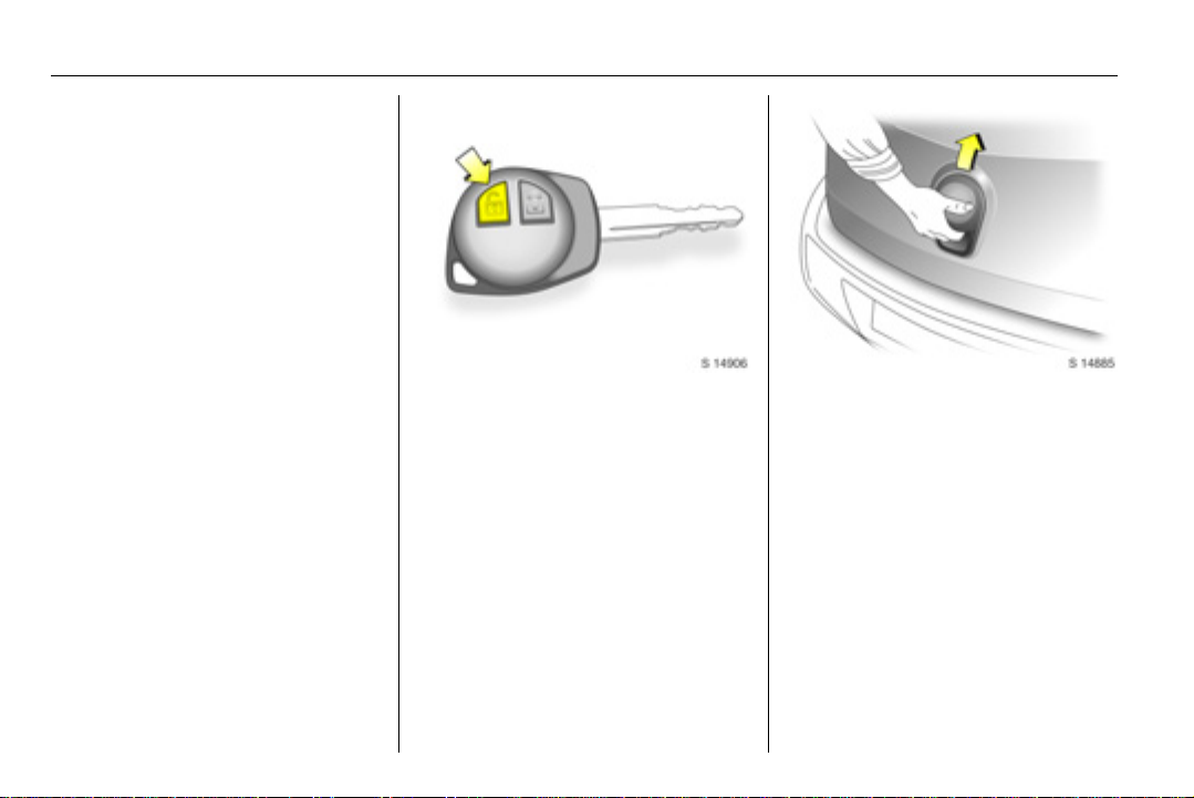
To unlock and open the
vehicle: Press button c on
remote control 3 or unlock
with the key, pull door
handle
Door locks 3 2-3, 5-12, keys 3 2-1,
immobiliser 3 2-7, radio remote
control 3 2-1, central locking system
3 2-3, ant i-theft locking system 3 2-6.
To unlock and open the
tailgate: Press button c on
remote control 3 or unlock
with the key, operate button
below the handle
Tailgate 3 2-5, radio remote control 3
2-1, central locking system 3 2-3.
Page 8
1-2In brief
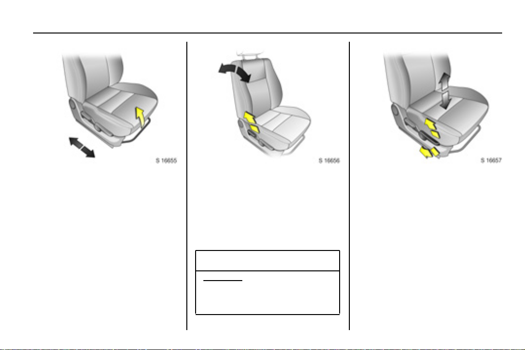
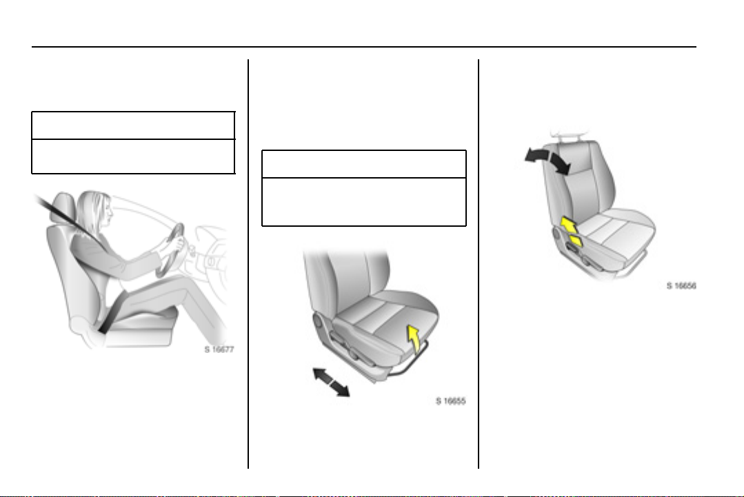
Longitudinal seat
adjustment: Pull handle,
slide seat, release handle
Seats 3 3-2.
Reclining seatbacks: Raise
release lever
Move seatback to suit seating
position.
Do not lean on seatback whilst
adjusting it.
Seats 3 3-2.
9 Warning
Important: Do not sit nearer than
10 inches (25cm) from the
steering wheel, to permit safe
airbag deployment.
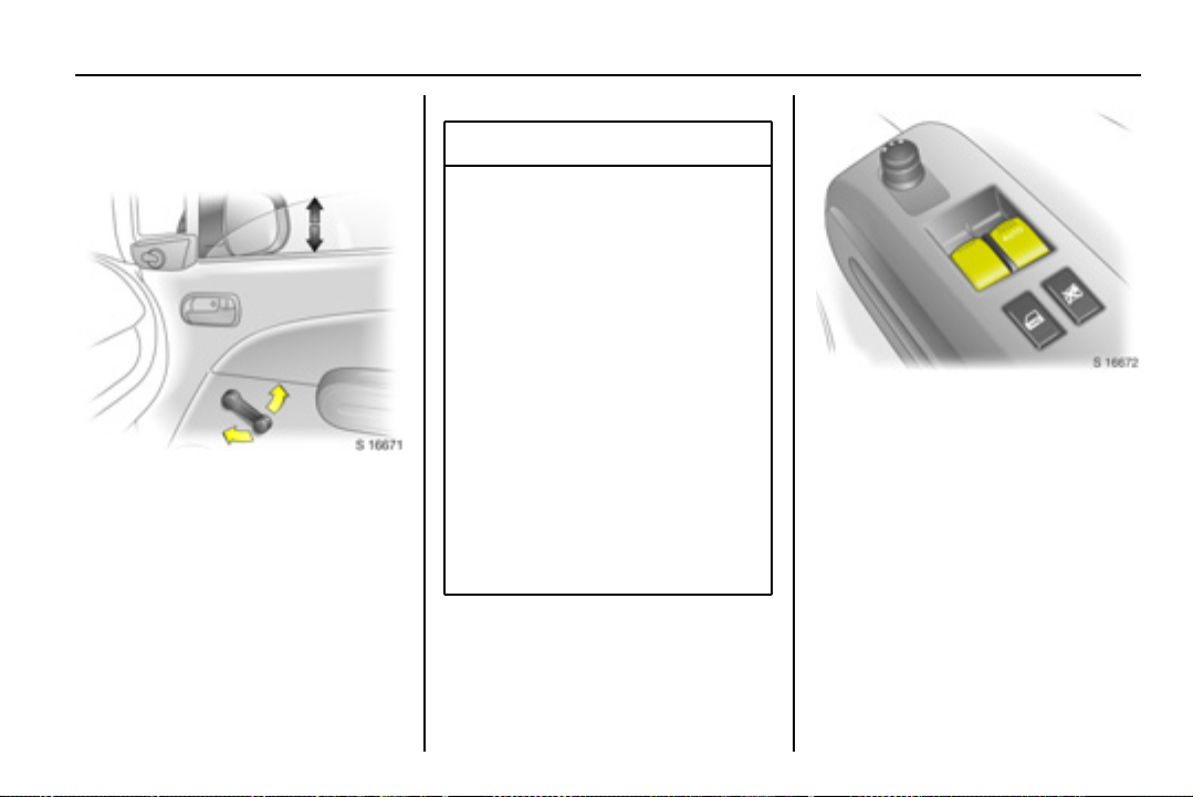
Adjusting seat height 3:
Raise or lower lever
Lever pumping action
Upwards: Raises seat
Downwards: Lowers seat
Seats 3 3-2.
Page 9
1-3 In brief
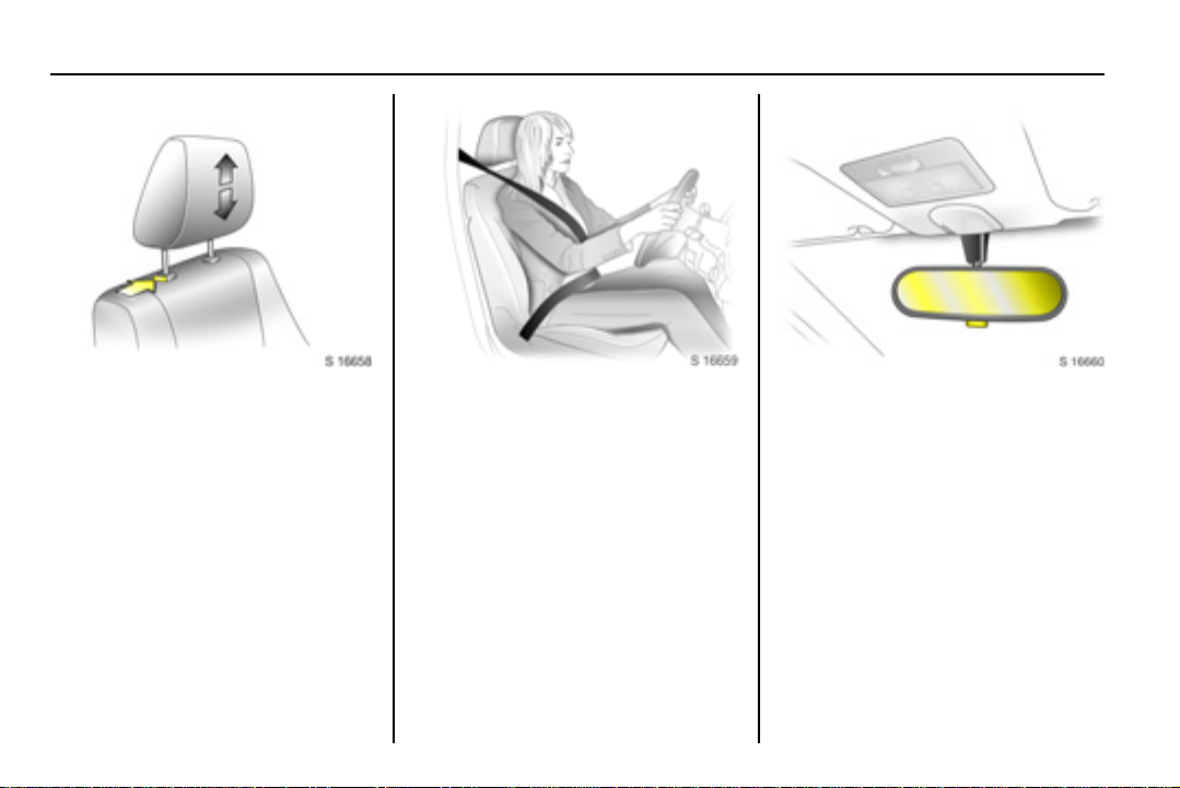
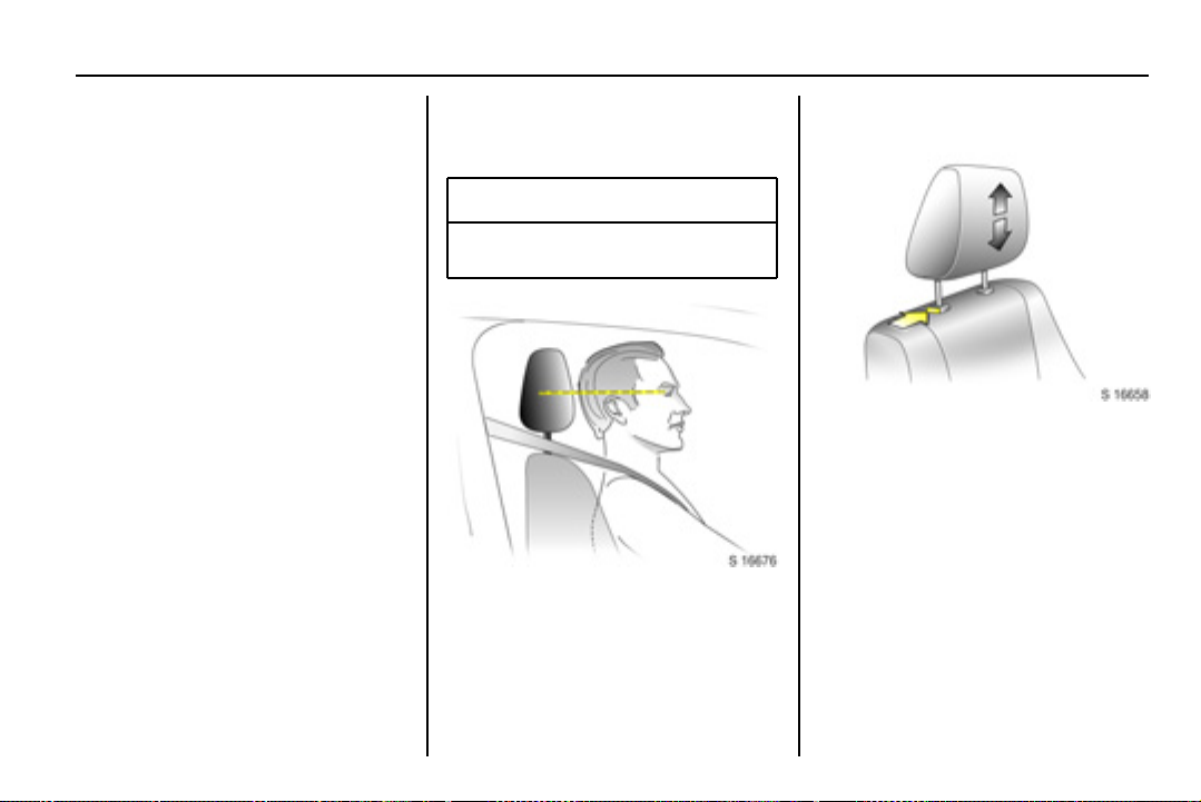
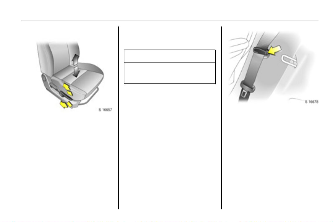
Adjusting head restraint
height: Press catch, adjus t
height, then release
Head restraints 3 3-1.
Fitting seat belt: Pull belt out
evenly from retractor, guide
over shoulder and engage in
buckle
The seat belt must not be twisted at
any point. The lap belt must lie snugly
against the body.
The seatbacks must not be tilted back
too far (recommended maximum
tilting angle approx. 25°).
To release seat belt, press red button
on belt buckle.
Seat belts 3 3-5 to 3-8, airbag system
3 3-13, seat position 3 3-2.
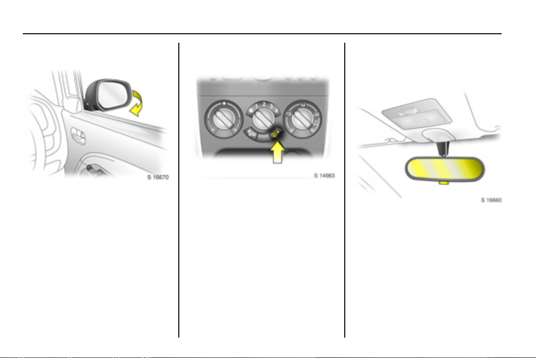
To adjust interior mirror:
Swivel mirror housing
Swivel lever on underside of mirror
housing to reduce dazzle at night.
Take care when driving with interior
mirror adjusted for night vision. Rear
view may be slightly distorted in this
position.
Further information 3 2-9.
Page 10
1-4In brief
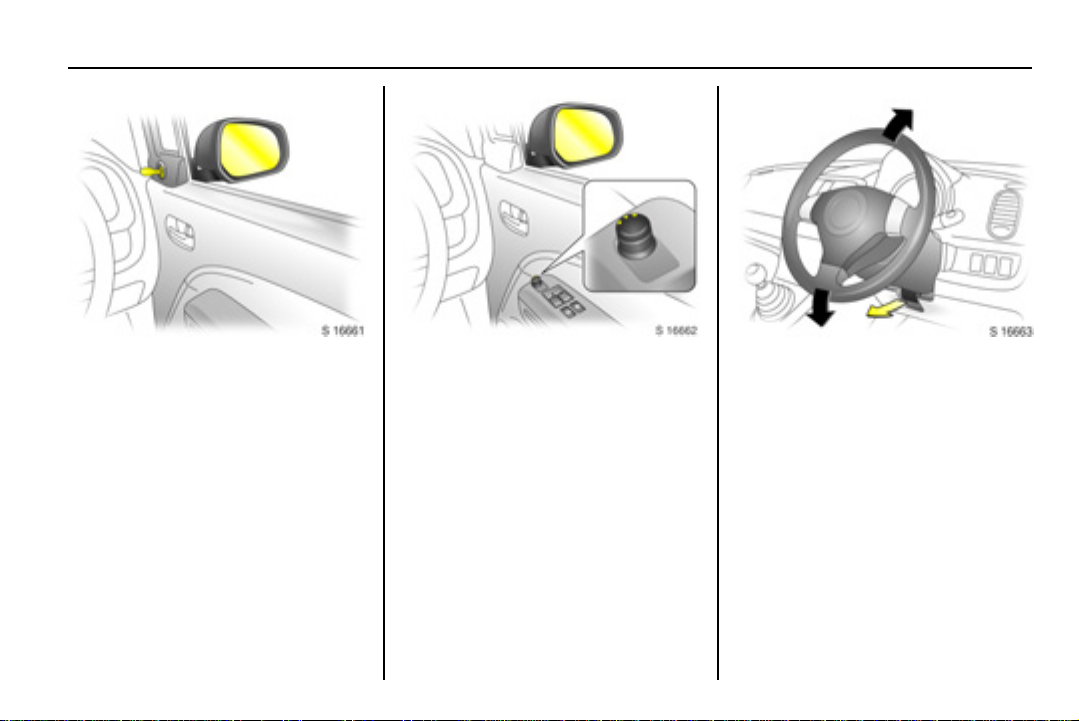
Adjusting manual exterior
mirrors: Swivel lever in
required direction
Exterior mirrors 3 2-8, heated exterior
mirrors 3 2-9, 8-5.
Adjusting power exterior
mirrors 3: Four-way switch
in driver’s door
Select corresponding mirror and
adjust.
Exterior mirrors 3 2-8, heated exterior
mirrors 3 2-9, 8-5.
To adjust steering wheel 3:
Pull lever forwards, adjust
height, push l ever back and
engage
Adjust steering wheel only with
vehicle stationary and steering
column lock released.
Airbag system 3 3-13, further
information 3 5-1.
Page 11
1-5 In brief
Page 12

1-6In brief
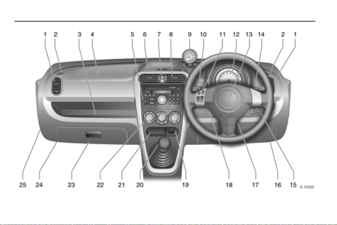
1 Side air vent s . .... .... .... .... ... 3 8-5
2 Door window defroster
vents ................................. 3 8-5
3 Storage tray . ..................... 3 4-2
4 Front passenger’s airbag 3 3-13
5 Infotainment system.......... 3 7-1
6 Upper tray ......................... 3 4-2
7 Hazard warning................. 3 6-2
Control indicator for
front passenger airbag
deactivation 3 ........ .. .... ... 3 3-18
8 Centre air vents................. 3 8-4
9 Tac homet er .... .... .... .... .... ... 3 5-6
10 Parking lamps ................... 3 6-1
Turn signal lamps .............. 3 6-2
High beam......................... 3 6-2
Dipped beam............. 3 6-1, 6-2
Headlamp flash ................. 3 6-2
Rear fog lamp .... .. .. .... .. .. ... 3 6-3
11 Steering wheel mounted
remote control 3 .. .. .... .... ... 3 7-2
12 Central information display
for time and outside
temperature .... .. .. .... .. 3 5-3, 5-4
Instrument cluster.............. 3 5-8
Speedometer..................... 3 5-5
Odometer ......................... 3 5-6
Fuel gauge ........................ 3 5-7
Service interval display 3 3 5-14
Transmission display 3..... 3 5-7
Trip computer 3 .. .. .... .... .. 3 5-14
13
Driver’s airbag................. 3 3-13
Horn .. .... .... .... .... .... .... .... .... 3 5-2
14 Windscreen wiper/wash .... 3 5-2
Rear window wiper/wash .. 3 5-3
15 Front fog lamps 3.... .. .. .... .. 3 6-3
Headlamp range
adjustment 3 ..................... 3 6-1
TCSS deactivation 3 ....... 3 9-11
16 Bonnet release ................ 3 10-2
17 Ignition swit ch.. .. .... .... .... .... 3 9-1
18 Steering wheel adjustment 3 5-1
19 Power outlet..................... 3 5-4
Cigarette lighter 3 ............ 3 5-5
20 Gear s hift lev er. .. .... .... 3 9-4, 9-6
21 Storage tray
22 Climate controls .. .. .. .... .... . 3 8-1
23 Glove box.... .. .... .... .... .... ... 3 4-1
24 Fuse box ...................... 3 10-12
25 Passenger airbag deactivation
switch 3.......................... 3 3-17
Page 13
1-7 In brief
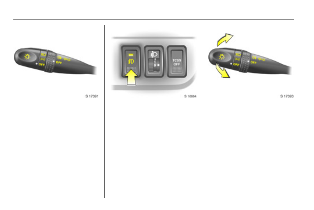
Exterior lamps controls:
Turn light switch:
P = Dipped beam
or high beam
8 = Parking lamps
OFF = Off
Turn adjustment band:
r = Rear fog lamp
OFF = Off
Press button:
> = Front fog lamps 3
Headlamp warning device 3 5-13,
further information 3 6-1, headlamp
range adjustment 3 6-1, fog lamps
3 6-3, headlamps when driving
abroad 3 6-3.
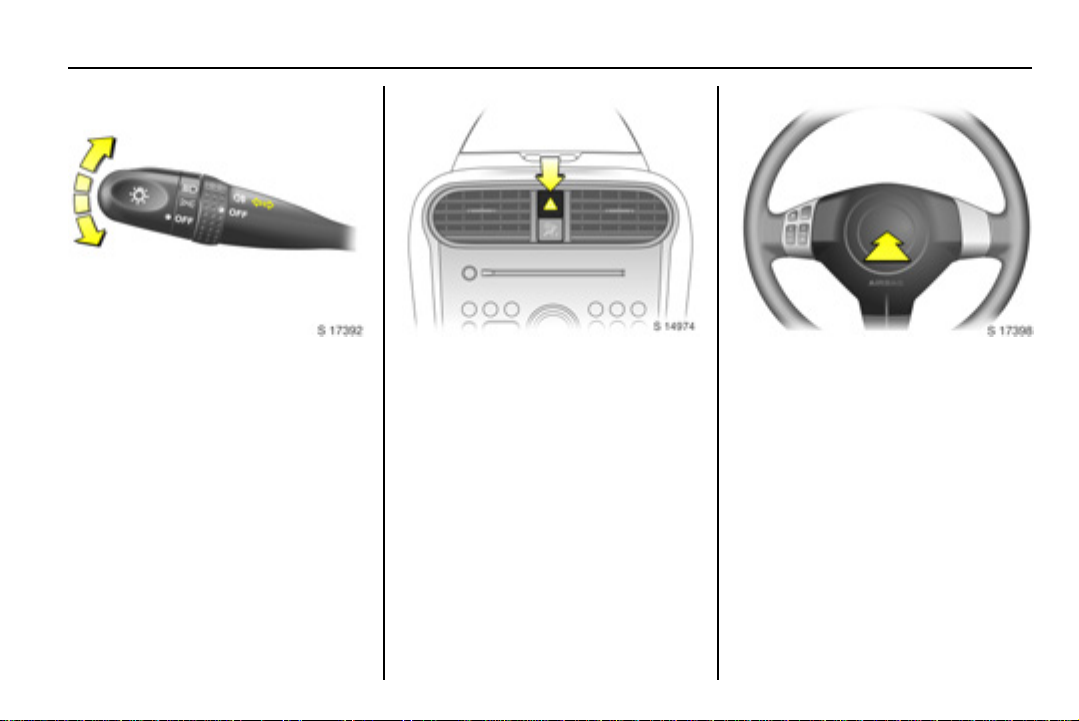
Headlamp flash, high beam
and dipped beam:
Headlamp
flas h
High beam = Push lever
Dipped beam = Pull lever back
Further information 3 6-2.
= Pull lever
towards steering
wheel
forwards
towards steering
wheel
Page 14
1-8In brief
Turn signal lamps:
Upw ards = Right t urn
Dow nwards = Left turn
Further information 3 6-2.
Hazard warning lamps: Horn: Press j
On = Press ¨
Off = Press ¨ again
Airbag system 3 3-13, remote control
on steering wheel 3 3 5-1, 7-2.
Page 15
1-9 In brief
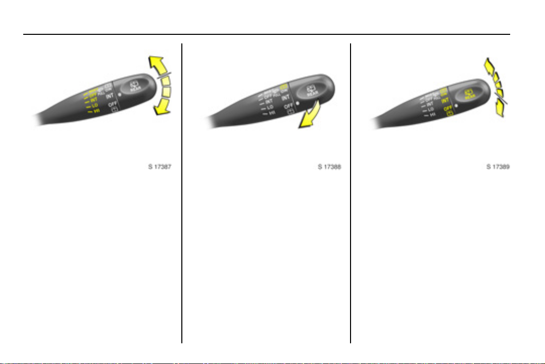
Windscreen wiper:
MIST = Misting function
OFF = Off
INT = Timed interval wipe 3
LO = Slow
HI = Fast
Move lever up f rom position OFF:
Single swipe.
Windscreen wiper 3 5-2, further
information 3 10-5, 10-30, 10-31.
Windscreen wash system:
Pull lever towards steering
wheel
Windscreen wash system 3 5-3,
further information 3 10-5, 10-30,
10-31.
Rear window wiper and
wash systems: Rotate end
of lever
f =Wash
ON = Wiper on
INT = Timed interval wipe 3
OFF = Wiper off
f =Wash
Rear window wiper/wash systems
3 5-3, further information 3 10-5,
10-30, 10-31.
Page 16

1-10In brief
Parking the vehicle:
Apply the parking brak e firmly
without actuating the release
button. On a downhill or uphill
slope, apply as firmly as possible.
Depress foot brake at the same
time to reduce operating forces.
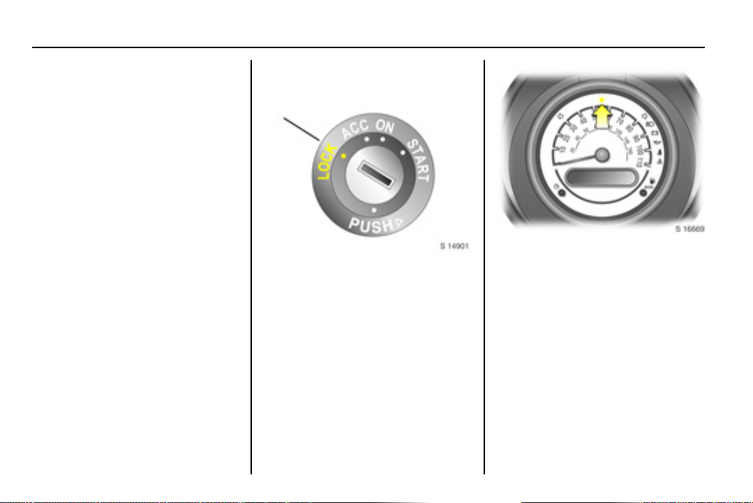
Push key into ignition switch before
turning to LOCK position and
removing (vehicles with automatic
transmission 3: depress foot brake
and shift into P). Turn steering
wheel until lock is felt to engage
(anti-theft protection).
If the vehicle is parked on a level
surface or a hill, select 1st gear
before switching the ignition off,
(vehicles with automatic
transmission 3: shift into P). Also
turn front wheels away from kerb if
parked on an uphill slope.
If the vehicle is parked on a
downhill slope, select reverse gear
before switching the ignition off,
(vehicles with automatic
transmission 3: shift into P). Also
turn front wheels towards kerb.
Lock doors and tailgate by pressing
button e on the radio remote
control 3. Press button e twice
within 3 seconds to activate the
anti-theft locking system 3.
Advice when parking:
Do not park the vehicle on an easily
ignitable surface. The high
temperature of the exhaust system
could ignite the surface.
Close the windows.
The engine cooling fans may run
after the engine has been switched
off 3 10-1.
Radio remote control 3 3 2-1,
central locking system 3 2-3.
Page 17
2-1 Keys, doors and windows
Keys, doors and
windows
Keys and locks ..................... 2-1
Doors. .. .. .... .. .. .... .. .. .... .. .. .... .. . 2-5
Vehicle security.................... 2-6
Ex terio r mirrors.. .. .. .... .. .. .... .. . 2-8
Interior mirror . .. .. .... .. .. .... .. .. ... 2-9
Windows............................... 2-10
Keys and locks
Keys
The key number is specified on the
keys or on a key number tag 3.
Remove key number tag from keys
and make a note of the number.
The key is a constituent of the
immobiliser 3. In c ase of lo ss ,
replacement keys can be ordered
from your Vauxhall Authorised
Repairer by quoting the key number.
Ordering keys from a Vauxhall
Authorised Repairer guarantees
problem-free operation of the
immobiliser 3.
Keep spare key in a safe place.
Locks 3 10-30.
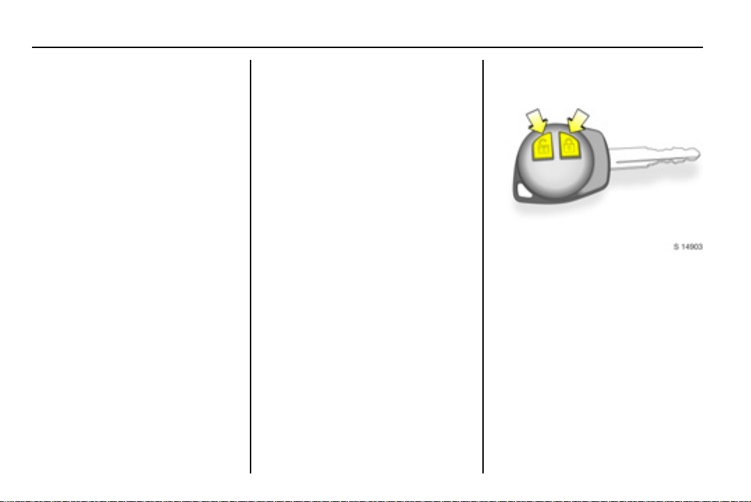
Radio remote control 3
The remote control is used to
operate:
Central locking system,
Anti-theft locking system 3.
The remote control has a range of
approx. 5 metres. The range may be
reduced due to environmental
conditions or s hadowing and
reflection of the radio waves.
Treat the remote control unit with
care: it should be protected against
moisture, kept out of direct sunlight
and should not be operated
unnecessarily.
Page 18
2-2Keys, doors and windows
Fault
If the central locking system cannot
be operated with the remote control,
this may be due to the following
reasons:
The remote control is out of range.
The battery voltage of the remote
control is too low. Change the
battery in the remote control unit.
Interference from higher power
radio waves from other sources.
Lock or unlock the doors manually
using the key or central locking switch
3 2-3, 2-4.
Seek the assistance of a workshop to
rectify the cause of the fault.
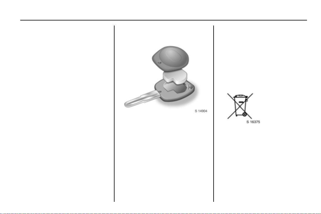
Changing battery in remote
control unit
Replace the battery (CR 1620 or
equivalent) in accordance with the
chapter “Service and maintenance”
3 11-2 or w hen the range of the
remote control starts to become
reduced.
Remove screw on key cover and
remove the transmitter.
Prise apart both halves of transmitter
with a suitable screwdriver.
Replace battery, ensuring the new
bat tery is ins talled corr ectly wi th
positive (+) side facing the pos itive
(+) terminal.
Reattach both halves of transmitter
and reinstall in holder, ensuring it
engages correctly.
Replace cover and tighten screw.
Battery disposal
Batteries are not to be treated as
household waste. They should be
disposed of at a designated collection
point for recycling.
Page 19
2-3 Keys, doors and windows
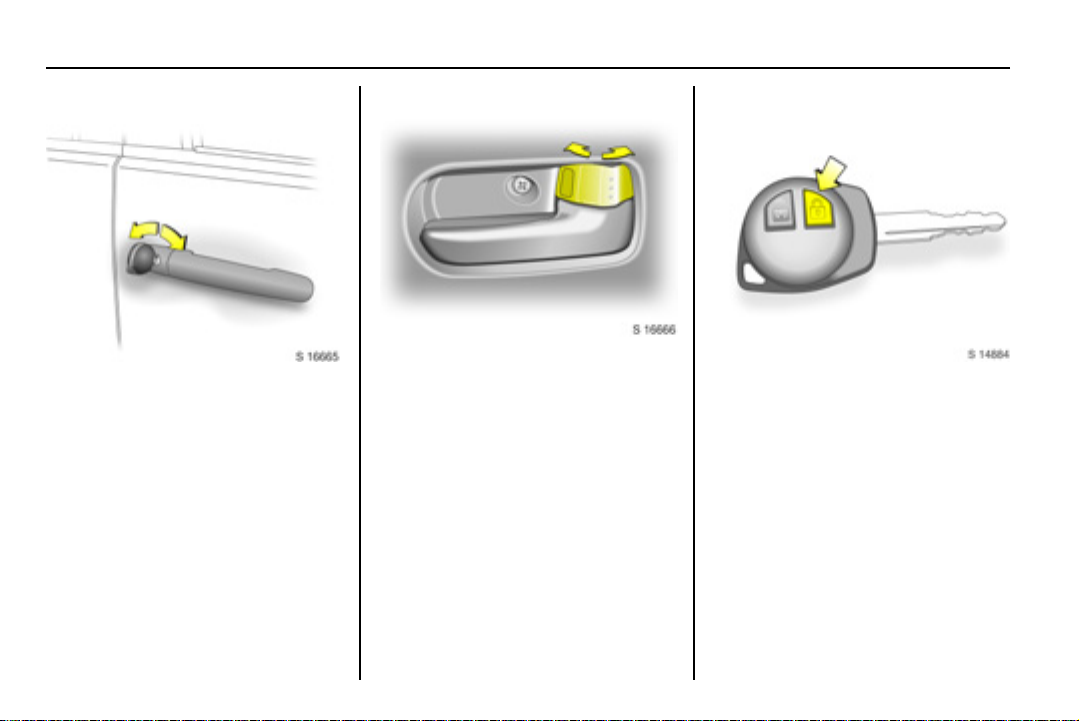
Door locks
The front doors may be manually
locked and u nlocked using the key.
On vehicles with central locking
system 3, the entire vehicle can be
unlocked by turning the key twice in
the driver’s door lock.
The tailgate is unlocked when the
driver’s door is opened.
To lock or unlock doors from inside
the vehicle, press the interior lock.
To lock front doors from outside the
vehicle, press the interior lock and
keep exterior door handle raised
when closing the door.
Central locking system 3
For front doors, rear doors and
tailgate.
To lock :
Press button e on remote control:
Hazard warning lamps flash once.
All doors and the tailgate are locked.
Always ensure that the doors,
bonnet, tailgate and windows are
properly closed before locking the
vehicle.
Page 20
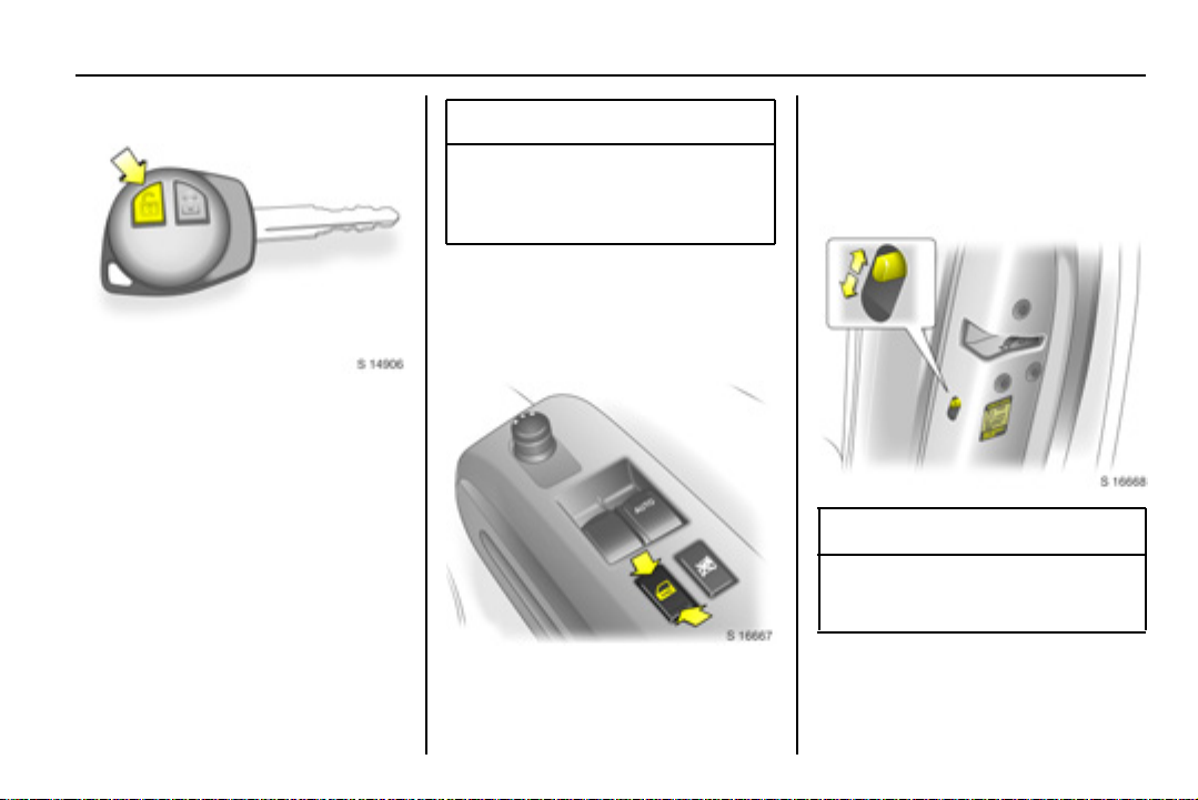
2-4Keys, doors and windows
To unlock driver’s door only:
Press button c on remote control
once:
Hazard warning lamps flash twice.
To unlock ent ire vehicle:
Press button c on remote control
twice:
Hazard warning lamps flash twice
with each press.
If no door is opened within approx.
30 seconds after the vehicle has
been unlocked via t he remote control,
the vehicle is relocked automatically.
9 Warning
For safety reasons, the vehicle
cannot be locked or unlocked via
the remote control if the key is in
the ignition switch.
The vehicle can also be manually
locked and unlocked by turning the
key in the driver’s door lock.
Central locking switch m
Use the central locking switch to lock
or unlock the doors and tailgate from
inside the vehicle.
Press the front part of the s witch to
lock or the rear part of the switch to
unlock all doors and tailgate.
Safety locks
9 W arning
Use the safety locks whenever
children are occupying the rear
seats.
To engage lock, open door and move
lock lever to lower position. Door
cannot then be opened from inside.
Page 21
2-5 Keys, doors and windows
To disengage safety lock, raise lock
lever.
Lockout protection
To prevent the driver from being
inadvertently locked out, the driver’s
door cannot be locked when it is
open.
Doors
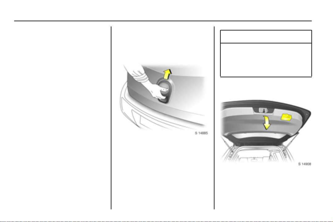
Tai lgat e
To o pen
The tailgate can be opened by
operating the button below the handle
and lifting the tailgate.
If the tailgate is open when the
ignition is switched on, control
indicator
instrument cluster.
9 illuminates in the
9 Warning
Do not drive with tailgate open or
ajar, e.g. when transporting bulky
objects, since toxic exhaust
gases could penetrate the vehicle
interior.
To close
There is a handle on the inside of the
tailgate for closing the luggage
compartment.
Page 22
2-6Keys, doors and windows
Close tailgate by pushing it down so it
latches securely. Ensure tailgate is
fully closed before driving.
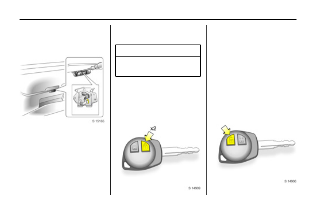
Emergency tailgate release
If the cent ral lock ing syst em 3 cannot
be operated with the remote control,
the tailgate can be opened from
inside the vehicle.
Fold rear s eats forward to allow
access to the tailgate (3 3-3) and
push up on emergency lever using a
suitable screwdriver to open the
tailgate.
Vehicle security
Anti-theft locking system 3
9 Warning
Do not use the system if there are
people in the vehicle. The doors
cannot be unlocked from inside.
All doors are secured agains t
opening and must be unlocked with
the vehicle key. Unlocking is not
possible in any other way, so keep
spare key in a safe place.
To lock:
All doors and t he tailgate must be
closed.
Press button e on remote control
twice within 3 seconds:
Hazard warning lamps flash twice.
- or Turn key in driver's door lock towards
rear of vehicle twice within
3 seconds.
Interior locks on all doors are
positioned such that doors cannot be
opened.
To unlock:
Page 23
2-7 Keys, doors and windows
To unlock driver’s door only: Press
button c on remote control:
Hazard warning lamps flash twice.
- or Turn key in driver’s door lock towards
front of vehicle once.
To unlock entire vehicle: Press
button c on remote control twice:
Hazard warning lamps flash twice
with each press.
- or Turn key in driver's door lock towards
front of vehicle twice.
Immobiliser 3
The system checks whether the
vehicle may be started using the key
that has been inserted. If the key is
recognised as "authorised", the
vehicle can be started. T he check is
carried out via a transponder housed
in the key.
The immobiliser is automatically
activated when the key is turned to
the LOCK position and removed from
the ignition switch.
The theft-deterrent control indicator
starts flashing after the key is turned
to positions LOCK or ACC, or
removed from the ignition switch.
Fault
If control indicator o or A flashes
after the ignition is switched on, there
may be a fault in the immobiliser
system. If the engine cannot be
started:
Turn key to LOCK position and
remove,
wait approx. 2 seconds,
then repeat starting proc edure.
Page 24
2-8Keys, doors and windows
If the control indicator fails to
extinguish, try to start the engine
using the spare key and seek the
assistance of a workshop to rectify
the cause of the fault.
Note
The immobiliser does not lock the
doors. Therefore, after leaving the
vehicle, always lock it 3 2-3.
Exterior mirrors
Convex mirrors
As exterior mirrors are convex,
objects are c loser than they appear.
Use interior mirror to judge size and
distance of objects.
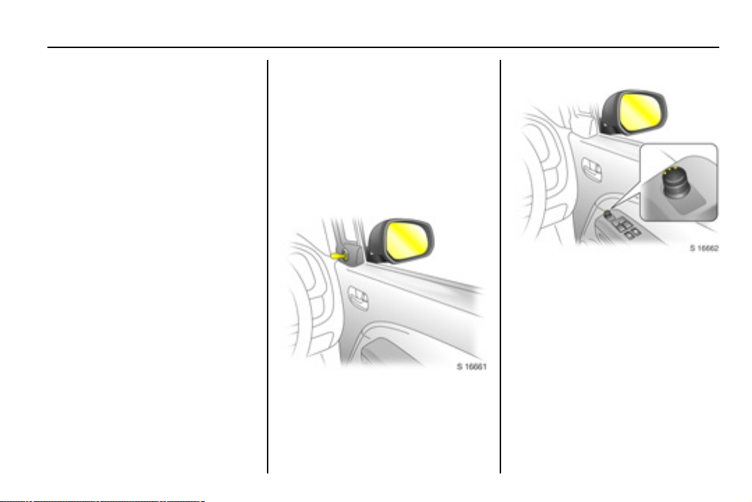
Manual mirrors
Adjust mirrors by swivelling lever in
required direction.
Electric mirrors 3
Adjust with the four-way switch in
driver’s door: Turn selector switch to
left or right; four-way outer part of
switch adjusts corresponding mirror.
The mirror glass swivels in the same
direction as the activation of the fourway switc h.
Return the selec tor sw itch to th e
central position to prohibit further
adjustment.
Page 25
2-9 Keys, doors and windows
Folding mirrors
For the safety of pedestrians, the
exterior mirrors will swing out of their
normal mounting position in the event
of an accident-like im pact.
Reposition the mirror by applying
slight pressure to the mirror housing.
Heated mirrors 3
The heating operates in conjunction
with the heated rear window using
button Ü.
Heated rear window, heated exterior
mirrors 3 8-5.
Interior mirror
Manual mirror
To adjust interior mirror, swivel mirror
housing.
Swivel lever on underside of mirror
housing to reduce dazzle at night.
Take care when driving with interior
mirror adjusted for night vision. Rear
view may be slightly distorted in this
position.
Page 26
2-10Keys, doors and windows
Windows
Manual windows
The door windows can be operated
with the crank.
Electric windows 3
9 Warning
Care must be taken when
operating the electric windows.
There is a risk of injury,
particularly for children, and a
danger that articles could become
trapped.
If there are c hildren on the front
passenger’s seat, press the z
switch in the driver’s door to
deactivate electric window
operation.
Keep a close watch on the
windows when closing them.
Ensure that nothing becomes
trapped in them as they move.
Before leaving the vehicle,
remove the ignition key in order to
prevent unauthorized operation.
Operational with key in ignition switch
position ON.
Driver’s and front pas senger’s door
windows are operated via two
switches located in the driver’s door.
For incremental operation, briefly pull
or press the appropriate switch.
For automatic opening of the driver’s
door window, press the switch down
fully and release it. Pull up the switch
to stop the window movement.
Page 27
2-11 Keys, doors and windows
An additional switch is located in the
front passenger’s door.
In the event of difficulty due to frost or
the like, pull the relevant window
switch several times until the window
is closed.
Child safety system
Press the z s witch in driver’s door to
deactivate front passenger’s door
electric window operation when a
child is occupying the seat.
Press switch again to activate electric
window operation.
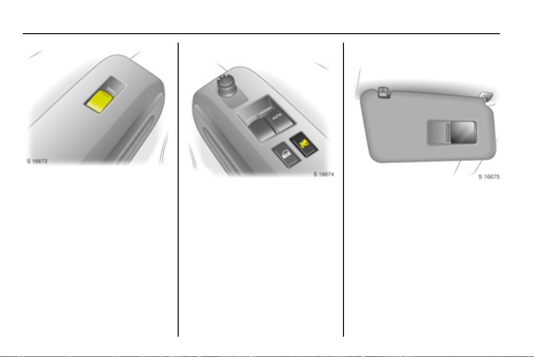
Sun visors
Use the sun visor to protect from
glare by pulling it up, down or
swivelling it to the side.
Depending on equipm ent version,
sun visors also have vanity mirrors 3.
Page 28
3-1Seats, restraints and interior
Seats, restraints
and interior
Head restraints . .................... 3-1
Front seats............................ 3-2
Rear seats ............................ 3-3
Seat b elts .... .... .. .. .... .. .. .... .. .. .. 3 -5
Child rest rain ts .... .. .. .... .. .. .... .. 3-9
Airbag system ....................... 3-13
Head restraints
Head restraint position
9 Warning
Only drive with head restraints
correctly adjusted.
For maximum protection, the middle
of the head restraint should be at eye
level. If this is not pos sible for
extremely tall persons, set to highest
position, and set to lowest position for
extremely small persons.
Height adjustment
To adjust head restraint height, press
catch, adjust height to suit then
release the catch.
Removal
Press catch. Pull up and remove the
head restraint.
Stow head restraints securely in
luggage compartment.
Page 29
3-2 Seats, restraints and interior
Front seats
Seat position
9 W arning
Only drive with the seats correctly
adjusted.
Adjus t driver’s seat such that, w ith the
driver sitting upright, the steering
wheel is held in the area of its upper
spokes with the driver’s arms slightly
bent.
Slide front passenger’s seat as far
back as it will go.
The seatbacks must not be tilted back
too far (recommended maximum
tilting angle approx. 25°).
Longitudinal seat
adjustment
9 Warnin g
Never adjust seats whilst driving,
as they could move
uncontrollably.
To adjust, pull the handle on the front
seat, slide the seat and release the
handle.
Ensure seat audibly latches into
position before driving.
Reclining seatbacks
To adjust, raise the release lever,
move seatback to suit seating
position and release lever to lock
seatback in position.
Do not lean on the seatback whilst
adjusting it.
Page 30
3-3Seats, restraints and interior
Adjusting seat height 3
To adjust, operate lever on side of
seat.
Lever pumping action
Upwards: Raises seat
Downwards: Lowers seat
Rear seats
Folding rear seatbacks
9 Warning
When adjusting the rear
seatbacks, use caution; beware
of moving parts.
The luggage compartment can be
enlarged by folding the rear
seatbacks onto the seat cushions.
Ensure front seats are not in reclined
position and push rear seat head
restraints all the way down.
When folding the rear seatbacks,
ensure the seat belts are unbuckled.
Route outboard rear s eat belts,
including the latch plates, through
their respective belt holders (as
illustrated), ensuring they are not
twisted at any point.
Page 31

3-4 Seats, restraints and interior
Unlatch detachable connector on
centre rear seat belt by inserting the
ignition key in the slot on t he
connector and allow the belt to
retract.
Insert latch plate into the slit on t he
belt webbing and insert detached
connector latch plate in roof holder
slot to the rear of the belt webbing.
To fold outboard rear seatbacks
separately 3, pull seatback release
lever downwards, fold seatback
forwards and down onto seat
cushion.
Page 32

Seat belts
Three-point seat belt
3-5Seats, restraints and interior
To fold rear bench seat 3, pull both
outboard seatback release levers
downwards simultaneously, fold
seatback forwards and down onto
seat cushion.
Do not allow passengers to sit on
folded seatbacks, or place any
unrestrained loads on them.
Restoring rear seatbacks
Raise seatback and push back to its
original position. Ensure seatback
latches into place by pushing top of
seatback and pulling it forwards
again.
Pull detached connector lat ch plat e of
centre rear seat belt from roof holder
slot and insert in connector, with the
arrows aligned. Ensure the latch plate
and connector audibly engage.
Release outboard rear seat belt s
from their respective belt holders.
The f ront and rear s eats are equipped
with three-point seat belts with
automatic retractors and locking
devices, allowing freedom of body
movement when the vehicle moves at
a constant speed, although the
spring-tensioned belts are always a
snug fit.
The belt has a “vehicle sensitive
retractor” which is designed to lock
during heavy acceleration or
deceleration in any direction.
Page 33

3-6 Seats, restraints and interior
9 W arning
Always wear your seat belt, also
in urban traffic and when you are
a rear seat passenger. It can save
your life!
In the event of an accident, persons
not wearing seat belts endanger their
fellow occupants and themselves.
Control indicator X for driver’s seat
belt reminder 3 5-9.
Seat belts are designed to be used by
only one person at a time. They are
only suitable for children aged up to
12 years or smaller than 150 cm if
used in conjunction with a child
restraint 3.
Belt force limiters
Load limiters on t he front seats
reduce the impact on the seat
occupant’s body from a tensioning
belt, in the event of frontal collisions
or rear impacts of a certain severity.
The belt force is controlled, to reduce
the risk of belt-inflicted injury.
Belt t ensioners
The seat belt systems on the front
seats incorporate belt tensioners
housed in the belt buckles and seat
belt retrac tors .
In the event of frontal collisions or
rear impacts of a certain severity, belt
buckles and s eat belt retractors
tighten the seat belts; the shoulder
and lap belts are instantaneously
tightened to fit the occupant’s body
more snugly.
9 Warning
Improper handling (e.g. removal
or installation) can activate the
belt tensioners.
The belt tensioners actuate only once
and must be replac ed after activation.
Seek the assistance of a workshop.
The belt tensioners only actuate
once, indicated by continuous
illumination of control indicator v in
the instrument cluster 3 5-9.
Deployed belt tensioners must be
replaced. Seek the assistance of a
workshop.
Accessories not released f or your
vehicle type and other objects must
not be fixed or placed within the
action zone of the belt tensioners,
as they may result in injury if the
belt tensioners are triggered.
Page 34

How to wear seat belts
pr op er ly
3-7Seats, restraints and interior
Pull the belt out evenly from the
retractor and guide it over the
shoulder, making certain that it is not
twisted at any point. The belt must not
rest against your neck or arm.
The seatback must not be tilted back
too far (the recommended maximum
tilting angle is approx. 25°).
Insert the latch plate into the buckle.
Seat belt buckles are designed such
that latch plates cannot be inserted in
the incorrect buckle.
The lap belt must not be twisted and
must fit snugly across the body.
Tension the belt frequently whilst
driving by tugging the diagonal part of
the belt.
The centre rear seat belt position has
a twin buckle arrangement. Engage
the smaller latch plate (1) into the
correct buckle, then pull the belt
across and audibly engage into the
buckle marked CENTER (2).
9 W arning
The belt must not rest against
hard or fragile objects in the
pockets of your clothing. Do not
place any objects (e.g. handbags)
between the belt and your body.
Control indicator X for driver’s seat
belt reminder 3 5-9.
Page 35

3-8 Seats, restraints and interior
Seat belt height adjustment
Height adjustment of front seat belt
upper anchorage points.
Do not adjust height whilst driving.
Pull out lock knob and slide
adjuster up or down to desired
position.
Ensure sliding height adjuster
latches into position.
Removing the belt
To remove the belt, press the red
release button on the belt buckle; the
belt will retract automatically.
Guide the belt as it retracts, to
prevent personal injury and damage
to interior surfaces .
Seat belt use during
preg na ncy
9 Warning
On pregnant women in particular,
the lap belt must be positioned as
low as possible across the pelvis
in order to prevent pressure on
the abdomen.
Seat belt care
Periodically inspect all parts of the
belt system for damage and to make
sure they are functioning properly.
Have damaged parts replaced. After
an accident, belts and triggered belt
tensioners must be replaced by new
ones.
Do not perform any alterations on the
belts, their anchorages, the automatic
retractors or the belt buckles.
Make sure that belts are not
damaged or trapped by sharp-edged
objects.
Page 36

3-9Seats, restraints and interior
Child restraints
Child restraint systems 3
When a child restraint system is
being used, pay attention to the
following usage and installation
instructions and also those supplied
with the child restraint system.
The country in which you are driving
could require the use of child restraint
systems at specific seats. Follow all
local and national regulations.
9 Warning
When using a child restraint
system on the front passenger’s
seat, the airbag systems for the
front passenger’s seat must be
deactivated; if not, the triggering
of the airbags poses a risk of fatal
injury to the child.
This is especially the case if rearfacing child restraint systems are
used on the front passenger’s
seat.
Selecting the right system
Your child should be transported
facing rearwards in the vehicle for as
long as possible. It is appropriate to
change the system when the child’s
head can no longer be properly
supported at eye height. The child’s
cervical vertebrae are still very weak
and in an accident they suffer less
stress in the semi-prone rearward
position than when sitting upright.
Children under 12 years or under
150 cm tall should only travel in an
appropriate c hild safety seat.
Never carr y a chi ld whils t t ravelling
in the vehicle. The child will
become too heavy to hold in t he
event of a collision.
When transporting children, use a
child restraint system that is
suitable for the child's weight, age
and height.
Ensur e t hat the ch ild re st rai nt
system to be installed is compatible
with the vehicle type.
Ensure that the mounting location
of the child restraint system within
the vehicle is correct.
Only allow children to enter and exit
the vehicle at the side facing away
from the traffic.
When the child restraint system is
not in use, secure the seat with a
seat belt or remove it from the
vehicle.
A child restraint system which has
been subjected to stress in an
accident must be replaced.
Vauxhall produce a range of child
restraint systems. We recommend
you consult a Vauxhall Authorised
Repairer.
Page 37

3-10 Seats, restraints a nd interior
Child restraint installation locations
Mass group Front passenger’s seat Outboard rear
Centre rear seat
seats
airbags
activated
Group 0: up to 10 kg
or approx. 10 months X U
Gr oup 0+: up to 13 kg
or approx. 18 months X U
Group I: 9 to 18 kg
or approx. 1 to 4 years X U
airbags
deactivated
1)
1)
1)
2)
U
2)
U
2)
U
X
X
X
Group II: 15 to 25 kg
or approx. 3 to 7 years X X U X
Group III: 22 to 36 kg
or approx. 6 to 12 years X X U X
1)
Only if front passenger’s seat airbag systems are deactivated 3 3 3-17.
Se at hei g ht 3 mu st b e in i ts up pe rmo st po sition 3 3-3.
Gr ou p 0 and 0+: Fron t pa ssen ger’s se at mu st b e in its rearmos t pos it ion 3 3-2.
Gr ou p I: When atta ching child r est ra ints by me an s of t hree -p oi nt se at belts, sea t be lt mu st r un forw ar ds fr o m th e anch or ag e po int 3 3- 8.
2)
Seat location with ISOFIX mountings available 3 3- 11 .
X = Seat position not suitable for children in this mass group.
U = Suitable for ’universal’ category child restraints, attached with the vehicle seat belt, approved for use in this mass group.
Page 38

3-11Seats, restraints and interior
ISOFIX child restraint
systems 3
Lower ISOFIX mountings
The ISOFIX mountings located
between the seatback and seat
cushion are used for mounting
ISOF IX child restra int sy stems on the
outboard rear s eats.
The instructions accompanying the
ISOF IX child rest raint sy st em are to
be expressly followed.
Only ISOFIX child rest r aint sy st ems
approved for the vehicle may be
used.
Top-Tether child restraint
mountings
The Top-Tether mountings located
on the rear of the seatbacks are
designed to hold child restraints
which come equipped with a toptether mounting strap only.
Please be sure to follow the
instructions provided with the child
rest raint system.
ISOFIX child restraint classes
The ISOFIX size class is shown on a
label attached to the child restraint
system.
A = Forward-facing child
rest raint for children of
maximum size in the weight
clas s 9 to 18 kg.
B = Forward-facing child
restraint for smaller children
in the weight class 9 to
18 kg.
B1 = Forward-facing c hild
restraint for smaller children
in the weight class 9 to
18 kg.
C = Rear-facing child restraint
for children of maximum
size in the weight class up
to 13 kg .
D = Rear-facing child restraint
for smaller children in the
weight class up to 13 kg.
E = Rear-facing child restraint
for young children in the
weight class up to 13 kg.
Page 39

3-12 Seats, restraints a nd interior
Permissible options for fitting an ISOF IX child restraint system
Mass group ISOFIX size
class
Group 0: up to 10 kg
or approx. 10 months E ISO/R1 - IL -
Gr oup 0+: up to 13 kg
or approx. 18 months E ISO/R1 - IL -
DISO/R2 - IL -
CISO/R3 - IL -
Group I: 9 to 18 kg
or approx. 1 to 4 years D ISO/R2 - IL -
CISO/R3 - IL -
B ISO/F 2 - IL, IU F
B1 ISO/F2X - IL, IUF
A ISO/F 3 - IL, IU F
1)
Head rest rain t m ust be i n its up per m ost locking po sition or remove d and stowed se curely in lugg ag e co m par tm en t.
2)
Head restraint must be removed and stowed securely in luggage compartment.
IL = Suitable for particular ISOFIX restraint systems of the ‘specific-vehicle’, ‘restricted’ or ‘semi-universal’ categories. The
ISOFIX restraint system must be approved for the specific vehicle type.
IUF = Suitable for ISOFIX forward-facing child restraint systems of universal category approved for use in this mass group.
- = No ISOFIX mounting locations available at this location.
Fixtur e Fro nt
passenger’s seat
Outboard rear
seats
1)
2)
1)
Centre rear
seat
-
-
-
Page 40

3-13Seats, restraints and interior
Airbag system
The airbag s ystem consists of several
individual systems.
When triggered, the driver’s and front
passenger’s airbags inflate to form
safety cushions for the driver and
front passenger.
When triggered, the side airbag
inflat es to form a saf ety cu shion fo r
the driver and/or front passenger in
the respective door area.
When triggered, the curtain airbag
inflates to provide a safety barrier in
the head area on the respective side
of the vehicle.
No impairment of view will occur, as
airbags inflate and deflate s o quickly
that they are often not noticed in an
accident.
9 Warning
The systems can be triggered
abruptly and cause injury if they
are handled improperly.
The airbag system and belt
tensioner control electronics can be
found in the centre console area. In
order to avoid malfunctions, do not
store magnetic objects in this area.
Do not stick or place any thing on
the steering wheel, instrument
panel, front seatbacks in the vicinity
of the airbags and seat areas or
cover them with other materials.
Each airbag can be triggered only
once. Once triggered, an airbag
must be replaced immediately.
Seek the assistance of a workshop.
Do not perform any m odifications to
the components of the airbag
system, as this will render the
vehicle unroadworthy.
We recommend having the
steering wheel, the instrument
panel, all panelling parts, the door
seals, handles and the front seats
removed by a workshop.
Control indicator for airbag systems
3 5-9.
Front airbag system
The front airbag system is identified
by the words AIRB AG and SRS
AIRBAG on the steering wheel and
above the glove box respectively.
Page 41

3-14 Seats, restraints a nd interior
The front airbag system will be
triggered depending on the severity
of the accident, and within the range
shown in the illustration.
The ignition must be switched on.
When triggered, the airbags inflate in
milliseconds. Forward movement of
the driver and front passenger is
checked and the risk of injuries to the
upper body and head are thereby
substantially reduced.
9 Warning
The front airbag system provides
optimum protection when the
seat, seat belt, seatback and
head restraint are c orrectly
adjusted as described 3 3-1 to
3-5.
Do not place objects, children or
pets in the area in which the
airbags inflate.
Page 42

Side airbag sy stem 3
3-15Seats, restraints and interior
9 Warning
The three-point seat belt must
always be c orrectly fitted 3 3-5.
The front airbag system serves to
supplement the three-point seat
belts.
The side airbags are identified by the
words SRS AIRBAG on the outboard
side of the front seatbacks and on the
B-pillar.
The side airbag system will be
triggered depending on the severity
of the accident and within the range
shown in the illustration.
The ignition must be switched on.
Page 43

3-16 Seats, restraints a nd interior
Curtain airbag system 3
When triggered, the airbags inflate in
milliseconds. The risk of injury to the
upper body and pelvis in the event of
a side impact is thereby substantially
reduced.
9 W arning
Do not place objects or parts of
your body in the area in which the
airbag inflates.
Note
Only install seat covers to the front
seats that have been approved for
your vehicle with side airbags.
The curtain airbag system is
identified by the words SRS AI RBAG
on the roof frame.
The curtain airbag system will be
triggered depending on the severity
of the accident and within the range
shown in the illustration.
The ignition must be switched on.
Page 44

3-17Seats, restraints and interior
When triggered, the airbags inflate in
milliseconds. The risk of injury to the
head in the event of a side impact is
substantially reduced.
9 Warning
Do not place any objects between
the airbag systems and the
vehicle occupants.
Only use hooks on the handles in
the roof to hang light articles of
clothing or coat hangers. Do not
place objects in the pockets of the
hanging items.
Passenger airbag
deactivation switch 3
The front and side airbags for the
front passenger’s seat must be
deactivated if a child restraint
syst em 3 is to be fitted on the front
passenger’s seat. The curtain airbag
syst em 3, the belt tensioners and all
driver’s airbag systems remain active
when the front passenger’s airbag
systems are deactivated. The front
passenger’s airbag s ystems are
active in the as-delivered condition.
The deactivation switch is located on
the side of the instrument panel on
the front passenger’s side of the
vehicle.
Control indicator * illuminates in the
instrument panel when the front and
side airbag s ystems for the front
passenger’s seat have been
deactivated.
The setting selected remains stored
when the ignition is switched on.
Deactivation
With the vehicle stationary and the
ignition switched off:
Insert ignition key in airbag
deactivation switch and turn to the
OFF position.
Page 45

3-18 Seats, restraints a nd interior
Activate the airbag systems with the
vehicle stationary and the ignition
switched off:
Insert ignition key in airbag
deactivation switch and turn to the
ON position.
Switch on ignition; c ontrol
indicator *
instrument panel then
extinguishes, to display the current
status.
Airbag systems for the front
Switch on ignition; control
indicator *
instrument panel then remains
illuminated, to display the current
status.
Airbag systems for the front
passenger’s seat are deactivated.
flashes in the
Activation
The airbag systems f or the front
passenger’s seat must be activated
when the child restraint system has
been removed and the seat is
occupied.
passenger’s seat are reactivated.
flashes in t he
Page 46

4-1Storage compartments
Storage
compartments
Int erior s towage .. .... .... .... .... .. 4-1
Luggage compartment .......... 4-3
Roof rac k sy stem 3 .. .... .. .. .... 4- 6
Interior stowage
Glove box
To open, pull handle.
To close, push lid until it latches int o
position.
Cup holders
Located in the front and rear of the
centre console between the front
seats.
Page 47

4-2 Storage compartments
Instrument panel storage
The front and rear cup holders are a
fixed size.
The instrument panel upper tray is
located above the centre air vents.
To open, lift front edge of lid.
To close, push lid down until it latches
into position.
9 Warnin g
Do not place glasses, CDs, CD
cases or flammable items, e.g.
cigarette lighter, in the instrument
panel upper tray when parked in
direct sunlight or in hot weather,
as the tray can become very hot.
The front passenger’s tray is located
above the glove box, for storing
maps, newspapers etc.
Page 48

4-3Storage compartments
Sunglasses storage
compartment 3
To open, pull cover down.
To close, push cover back up.
Luggage compartment
Notes on loading the vehicle
Heavy objec ts in the luggage
compartment s hould be placed as
far forward as possible. If objects
are to be stacked, heavier objects
should be placed at the bottom.
Secure heavy objects in luggage
compartment using lashing eyes 3.
If heavy loads slip when the vehicle
is braked heavily or driven around a
bend, handling of the vehicle may
change.
No objects should be placed on the
luggage compartment cover or the
instrument panel.
Do not allow the load t o protrude
above the upper edge of the rear
seatbacks, or if the rear seatbacks
have been folded down, above the
upper edge of the front seatbacks.
Loads must not obstruct the
operation of the pedals, parking
brake and gearshift lever or hinder
the freedom of movement of the
driver. Do not place any unsecured
objects in the interior.
Bulky objects should not be
transported with the tailgate open
or ajar, otherwise poisonous
exhaust fumes may enter the
vehicle.
The payload is the difference
between the permissible Gross
Vehicle Weight (vehicle
identification plate 3 12-1) and the
EC kerb weight.
Optional equipment and
accessories increase the kerb
weight and in some cases also the
Page 49

4-4 Storage compartments
permissible Gross Vehicle Weight,
which means that the payload will
also change slightly.
According to EC Directive, the
permissible Gross Vehicle Weight
includes assumed weights for
driver (68 kg), luggage (7 kg) and
all fluids (tank 90% full).
Note the weights given on the
vehicle identification plate.
The maximum permissible roof
load is 35 kg.
The roof load is the combined
weight of the roof rack and the load.
Vehicle speeds in excess of
75 mph (120 km/h) are not
recommended with a full roof load.
Driving hints 3 9-1.
Vehicle weights 3 12-7.
Luggage compartment
under floor storage 3
To access the under floor storage,
pull up floor carpet using the central
strap located near the tailgate latch
and hang the string on the hook
provided.
If necessary, the under floor storage
compartment can be removed from
the luggage c ompartment.
To remove, pull up by handle near the
tailgate latch.
To install, fit compartment into
brackets behind outboard rear
seatbacks, then push down near side
of compartment into clips on both
sides of luggage compartment.
Do not allow objects to protrude
above the top of the under floor
storage.
Page 50

4-5Storage compartments
Luggage compartment
cover
Do not place heavy objects on the
cover. Loose objects should be
secured safely in the luggage
compartment before driving.
To remove the luggage compartment
cover, pull either side of the cover
from the retaining lugs.
The luggage compartment cover can
be stowed in the under floor storage
compartment 3.
Warning triangle ¨ 3 and
first aid kit +
Your warning triangle and first aid kit
can be accommodated below the
floor cover in the luggage
compartment.
3
Page 51

4-6 Storage compartments
Roof rack system 3
For reasons of safety and to avoid
damaging the roof, we recommend
that you use roof rack systems
approved for your vehicle.
Fasten the roof rack to the roof rails
following the instructions that
accompany the system, ensuring that
the roof load is evenly distributed
over the side or cross rails. Loads
must not be placed on the roof
surface.
To prevent damage or loss, check
frequently t hat roof loads are securely
fastened.
Driving with a roof load affects the
vehicle’s centre of gravity: drive
carefully in crosswinds and do not
drive at high speeds.
Driving hints 3 9-1.
Page 52

5-1Instruments and controls
Instruments and
controls
Horn j ................................. 5-2
Windscreen wiper ................. 5-2
Windscreen wash system . .... 5-3
Rear window wiper/wash ...... 5-3
Cloc k ... .. .. .... .. .. .... .. .. .... .. .. .... .. 5-3
Outside temperature 3 ......... 5-4
Power outlets .. .... .. .. .... .. .. .. .. .. 5-4
Cigarette lighter ) 3 ............. 5-5
Ashtrays 3 .... .. .. .. .. .. .. .. .. .. .. .. .. 5 -5
Warning lights, gauges and
indic ators .... .. .. .... .. .. .... .. .. .... 5-5
Transmission display 3......... 5-7
Cont rol indic ators .. .. .... .... .... .. 5-8
Warning chimes .... .... .. .. .... .. .. 5-13
Service interval display 3 ..... 5-14
Engine oil life monitor 3.. .. .. .. 5- 14
Trip computer 3 .... .. .. .... .. .. .... 5- 14
Steering wheel adjustment
To adjust steering wheel 3, pull lever
forwards, adjust height, push lever
back and engage.
Adjust steering wheel only with
vehicle stationary and steering
column lock released.
Push the lever firmly backwards to
ensure that the steering wheel is
locked in position.
Steering wheel mounted
remote control 3
The functions of the Infotainment
system can be operated with the
buttons on the steering wheel.
Further information 3 7-2.
Page 53

5-2 Instruments and controls
Horn j
To activate horn, press steering
wheel.
Windscreen wiper
To activate, move lever:
MIST = Misting function
OFF = Off
INT = Timed interval wipe 3
LO = Slow
HI = F ast
Move lever up from pos ition OFF:
Single swipe.
Adjustable wiper interval 3
Set the lever to adjustable timed
interval wiper position INT.
Rotate INT TIME adjustment band
upwards for more frequent wiping
and rotate it downwards for less
frequent wiping.
Page 54

5-3Instruments and controls
Windscreen wash system
To activate, pull lever towards
steering wheel. Wash fluid is sprayed
onto the windscreen.
In vehicles with timed interval wipe
position INT 3, the wiper switches on
automatically at low speed if they are
not already activated.
Rear window wiper /wash
To activate wiper and wash, rotate
end of lever:
f =Wash
ON = Wiper on
INT = Timed interval wipe 3
OFF = Wiper off
f =Wash
Wash fluid is sprayed on to rear
window when the end of the lever is
turned to position
is released, it will spring back to the
ON/OFF position.
f. When the lever
Further information 3 10-5, 10-30,
10-31.
Clock
The time is shown in the odometer
display when the ignition is switched
on.
Correcting time
To set the clock, press and hold the
Ö butt on for approx. 2 seconds; c lock
display now in s etting mode.
Minute display flashes.
Press Ö to set minutes.
Page 55

5-4 Instruments and controls
Release Ö for approx. 5 seconds to
set minute display.
Hour display flashes.
Press Ö to set hours.
Release Ö for approx. 5 seconds to
set hour display.
Outside temperature 3
The outside temperature is shown in
the odometer display when the
ignition is switched on.
If outside temperature drops to near
freezing point (0 °C), the symbol :
illuminates in the odometer display as
a warning for icy road surfaces.
9 Warnin g
The road surface may already be
icy, even though the display
indicates a f ew degrees above
0°C.
Power outlets
Located on the instrument panel,
below the climate control switches.
Operational with ignition switch in
positions ACC or ON.
Pull the cap out to use the accessory
socket, and replace it when not in
use.
The use of non-authorised
accessories may cause damage to
the socket.
Use of accessory sockets while the
engine is not running will discharge
the battery.
The maximum power requirement of
electrical accessories must not
exceed 120 watts.
Do not connect any current delivering
accessories, e.g. electrical charging
devices or bat teries.
Connected electrical accessories
must comply with the EC standard in
terms of electromagnetic
compatibility requirements laid down
in DIN VDE 40 839, otherwise vehicle
malfunctions may occur.
Page 56

5-5Instruments and controls
Ciga rette li ght er ) 3
With ignition switch in positions ACC
or ON, push the cigarette lighter in all
the way and release it.
Heating up ceases once element is
glowing; cigarette lighter pops up
automatically. Withdraw lighter.
Ashtrays 3
9 Warning
To be used only for ash and not
for combustible rubbish.
Portable ashtray
The portable ashtray can be fitted in
the front or rear cup holder in the
centre console.
Warning lights, gauges
and indicators
Speedometer
Indicates the vehicle speed.
Page 57

5-6 Instruments and controls
Odometer
The odometer indicates how far the
vehicle has been driv en.
Trip odometer
There are two independent trip
odometers which indicate how far the
vehicle has been driven since the last
reset.
Press the MO D E button repeatedly
until A or B appears on the left of the
odometer display.
To reset a trip odometer, press and
hold the MODE button for approx.
2 seconds while the relevant trip
odometer is displayed.
Odometer display brightness
To change brightness level, switch on
headlamps and press the MODE
button repeatedly until the squares
that indicate the brightness level
appear in the odometer display. Then
press and hold the MODE button to
cycle through brightness levels.
Four squares indicates maximum
brightness, while one square
indicates the minimum brightness
level.
Tachometer
Indicates the engine speed .
Cau tion
Pointer in warning zone; maximum
permissible engine speed
exceeded, danger to engine.
Page 58

5-7Instruments and controls
Fuel gauge
Indicates fuel level when the ignition
is on ( F indicates full, E indicates
empty).
When fuel gauge indicates that fuel
supply is low (one segment on the
gauge is illuminated), fill up fuel tank
as soon as possible. If control
indicator
instrument cluster, refuel
immediately.
Never let the fuel tank become
empty. Diesel engines: if the tank has
been run dry, bleed the fuel system
3 10-7.
Y illuminates in the
Because of the amount of fuel
remaining in the tank, the amount of
fuel required to fill the tank may be
less than the specified tank capacity.
Refuelling 3 9-12.
Transmission display 3
Display of the selected gear or mode
with automatic transmission.
P Park position
R Reverse gear
N Neutral
D Automatic mode
3, 2, L Selected gear
Automatic transmission 3 9-3.
Page 59

5-8 Instruments and controls
Instrument cluster Control indicators
The control indicators described here
are not present in all vehicles. The
description applies to all instrument
versions.
The colours of the control indicators
mean:
Red
Yellow
Green
Blue
Danger, important
reminder.
Warning, information,
fault.
Confirmation of
activation.
Confirmation of
activation.
Page 60

5-9Instruments and controls
X Driver’s seat be lt
Will illuminate in red when ignition is
switched on if driver’s seat belt is not
engaged.
If vehicle speed exceeds 9 m ph
(15 km/h) and driver’s seat belt is not
engaged, the control indicator will
flash for approx. 90 seconds along
with a warning chime and then
illuminate until driver’s seat belt is
fastened correctly.
Seat belts 3 3-5.
v Airbag s ystems, belt
tensioners
Will flash in red several times when
the ignition is switched on, then
extinguish.
If it does not flash when the ignition is
switched on, stays lit, illuminates or
flashes whilst driving, there is a fault
with the airbag systems or with the
belt tensioners. The systems might
not therefore be triggered in the event
of an ac cident. Seek the assistance
of a workshop immediately.
Belt tensioners 3 3-6, airbags 3 3-13.
p Charging system
Will illuminate in red when ignition is
switched on. Extinguishes after
engine is started.
If it stays lit after the ignition is
switched on or illuminates during
driving: stop vehicle and switch off
engine. The battery is not being
charged and t he engine cooling may
be interrupted. The brake servo unit
may cease to be effective. Interrupt
your journey immediately.
Remove ignition key and check drive
belt condition and tensioning before
seeking the assistance of a
workshop.
s Service transmission 3
Will illuminate briefly in yellow when
the ignition is switched on.
If it f lashes, there is a fault in the
automatic transmission. Seek the
assistance of a workshop
immediately.
Autom atic tr ansm ission 3 9-3.
R Brake system
Will illuminate in red when ignition is
switched on. Extinguishes after
engine is started.
Illuminates when engine is running if
parking brake is applied and/or fluid
level for brake hydraulics is too low.
Caution
If it illuminates when the parking
brake is not applied: stop vehicle;
interrupt your journey immediately.
Seek t he assistance of a workshop.
Further information 3 9-9,
brake fluid level 3 10-6.
u Anti-lock Brake System
(ABS)
Will illuminate briefly in yellow when
ignition is switched on.
At t he same ti m e, the sy st e m
performs a self-check. W hen the
control indicator extinguishes, the
system is ready for operation.
Page 61

5-10 Instruments and controls
If it does not illuminate when the
ignition is switched on, stays lit or
illuminates during driving, t here is a
fault in the ABS. The vehicle’s brak e
system may remain operational
without ABS regulation.
If it illuminates during driving along
with brake system control indicator
R, there is a serious fault in the
brake system. Seek the assistance of
a workshop immediately, to have the
system checked.
Further information 3 9-9.
2 Power steering
Will illuminate in yellow when ignition
is switched on. Extinguishes after
engine is started.
If it does not illuminate when the
ignition is switched on, stays lit or
illuminates during driving, t here is a
fault in the system. Seek the
assistance of a workshop as soon as
possible.
TCSS OFF Traction Control
Support System off 3
Will illuminate briefly in yellow when
the ignition is switched on.
When the TCSS OFF switch (located
on the lower instrument panel) is
pressed, the control indicator
illuminates. The traction control
aspect of the Electronic Stability
Program (ESP
With ESP
slipping on wet, snowy or icy roads,
the traction control aspect of ESP
may switch off automatically and the
control indicator will illuminate. It will
extinguish automatically when
prevailing road conditions improve.
Further information 3 9-11.
R Electronic Stability
Program (ESP
Will illuminate briefly in yellow when
the ignition is switched on.
If it stays lit or illuminates during
driving, there may be a fault with
®
ESP
. Seek the assistance of a
workshop.
®
) is switched off.
®
active, if wheels are
®
) ac tive 3
®
If it flashes 5 times per second when
the engine is running, the system has
come into action. The engine output
may be reduced (the sound of the
engine changes) and the vehicle may
be braked automatically to a small
degree.
If it remains illuminated whilst driving,
there may be a fault with ESP
vehicle’s brake system remains
operational without ESP
®
. The
®
regulation.
Seek the assistance of a workshop to
have the cause of the fault remedied.
If the vehicle’s battery has been
disconnected and reconnected,
®
ESP
is deactivated and the control
indicator flashes once per second.
Reac tivate ESP
®
by driving in a
straight line at over 9 mph (15 km/h)
for a f ew seconds until flashing
ceases.
Further information 3 9-10.
ESP
Electronic Stability
Program (ESP
®
) fault 3
Will illuminate briefly in yellow when
the ignition is switched on.
Page 62

5-11Instruments and controls
If it stays lit or illuminates during
driving, there is a fault with ESP
The vehicle’s brake system remains
operational without ESP
Seek the assistance of a workshop to
have the cause of the fault remedied.
Further information 3 9-10.
®
®
.
regulation.
W Engine coolant
te mpera ture
Will illuminate briefly in red when
ignition is switched on.
If it illuminates or flashes when the
engine is running: stop vehicle and
switch off engine. Coolant
temperature is too high; danger of
engine damage. Check coolant level.
9 Warning
Allow engine to cool down before
removing coolant filler cap.
Further information 3 10-4.
N Preheating for diesel
engines 3
Will illuminate during engine
preheating.
Preheating s ystem switches on only if
outside temperature is low.
If it illuminates during driving or if the
engine cannot be started, seek the
assistance of a workshop as soon as
possible.
Starting the engine 3 9-2.
Z Exhaust emissions
Will illuminate in yellow when ignition
is switched on. Extinguishes after
engine is started.
If it illuminates when the engine is
running: fault in emission control
system. The permitted emission
limits may be exceeded. Fuel
economy and vehicle driveability may
be impaired. Seek the assistance of a
workshop immediately.
Diesel engines: The engine stops and
control indicator Z illuminates if the
fuel level is too low. If t he tank has
been run dry, bleed the fuel system 3
10-7.
Vehicles with electric throttle body
system 3: If the battery has been
disconnected, the system must be
recalibrated upon reconnection of the
battery. Hold ignition key in ON
position for 5 seconds without
running the engine. Control indicator
Z remains illuminated af ter the
engine is started if the procedure is
not successful.
I Engine oil pressure
Will illuminate in red when ignition is
switched on. Extinguishes after
engine is started.
If it illuminates during driving; engine
oil pressure may be dangerously low,
interrupting engine lubrication and
resulting in damage to the engine
and/or locking of the drive wheels:
Move out of t he flow of traffic as
quickly as possible without
impeding other vehicles,
Page 63

5-12 Instruments and controls
Depress clutch,
Move gearshift lever t o neutral
(automatic transmission 3 to N),
Switch off ignition.
9 W arning
When the engine is off,
considerably greater force will be
required for braking and steering.
Do not remove key until vehicle
has come to a standstill,
otherwise the steering column
lock could engage unexpectedly.
Check engine oil level. If the oil level
is low, top up using the specified
engine oil 3 10-3, 11-6, 12-3.
If the oil level is normal, seek the
assistance of a workshop to have the
vehicle’s lubricating system checked.
I Engine oil life monitor 3
For engines with diesel particle filter.
Will flash in red when engine oil and
filter require changing.
Engine oil life monitor 3 3 5-14.
o
Theft-deterrent
Will start flashing slowly in red after
the key is turned to positions LOCK or
ACC, or removed from the ignition
switch.
o Immobiliser
Control indicator o (or A for diesel
engines) illuminates when the ignition
is switched on, and extinguishes
when the engine is started.
If either control indicator flashes after
the ignition is switched on, there may
be a fault in the immobiliser system;
the engine c annot be started 3 2-7.
> Front fog lamps 3
Control indicator in button >, loc ated
on the lower instrument panel,
illuminates when front fog lamps are
switched on 3 6-3.
r Rear fog lamp
Will illuminate in yellow when the rear
fog lamp is switched on 3 6-3.
P High beam
Will illuminate in blue when the high
beam is on and when headlamp flash
is operated 3 6-2.
q Headlamp range
adjustment 3
Will illuminate during driving to
indicate a fault that requires
immediate attention. Seek the
assistance of a workshop as soon as
possible.
Further information 3 6-1.
9 Door ajar 3
Will illuminate in red when a door or
the tailgate is open.
A Service vehicle soon
(for diesel e ngines) 3
Will illuminate briefly in yellow when
ignition is switched on.
If it flashes when the ignition is
switched on, there may be a fault in
the immobiliser system; the engine
cannot be started (3 “o Immobiliser“,
3 2-7).
Page 64

5-13Instruments and controls
If it illuminates when the engine is
running; there may be a fault in t he
engine electronics: interrupt your
journey and seek the assistance of a
workshop.
If regeneration of the diesel particle
filter is not successful or possible (3
5-13 “8 Diesel particle filter 3“), the
control indicator may illuminate and
the vehicle goes into limp home
mode: interrupt your journey and
seek the assistance of a workshop
immediately.
Further information 3 9-7.
Y Low fuel
If it illuminates during driving; fuel
level is low: fill up fuel tank as soon
as possible.
Never let the tank run dry!
Erratic fuel supply c an cause catalytic
converter to overheat 3 9-8.
Diesel engines: The engine stops and
control indicator Z illuminates if the
fuel level is too low (3 5-11 “Z
Exhaust emissions”). If the tank has
been run dry, bleed the fuel system 3
10-7.
Refuelling 3 9-12, fuel tank capacity
3 12-5.
8 Diesel particle filter 3
Will illuminate briefly in yellow when
the ignition is switched on.
If it illuminates during driving, the
diesel particle filter requires cleaning.
As soon as the road and traffic
situation permits it, increase speed to
more than 50 m ph (75 km/h) for
approx. 30 minutes. The control
indicator extinguishes as soon as
cleaning is complete.
If regeneration of the diesel particle
filter is not successful or possible (3
5-12 “A Service vehicle soon 3“),
control indicator A may illuminate
and the vehicle goes into limp home
mode: interrupt your journey and
seek the assistance of a workshop
immediately.
Further information 3 9-7.
O Turn signal lamps
The appropriate control indicator will
flash in green when the turn signal is
on.
Rapid flash; failure of a turn signal
bulb or the corresponding fuse.
Both c ontrol indic ators flash when t he
hazard warning lamps are active.
Turn signal lamps 3 6-2, bulb
replacement 3 10-7, fuses 3 10-11.
Warning chimes
While driving:
when operating the turn signals.
if driver’s seat belt is not engaged
and vehicle speed exceeds approx.
9 mph (15 km/h).
When the vehicle is parked and
driver’s door is opened:
with exterior lamps s witched on
(and ignition key removed).
when the key is in the ignition
switch.
Seat belt warning chime 3 3-7.
Driving hints 3 9-1.
Page 65

5-14 Instruments and controls
Service interval display 3
In the case of vehicles with fixed
engine oil change and service
intervals, InSP appears in the
odometer display if the ignition is
switched on when servicing is
overdue: have the next service
carried out within one week or
300 miles (500 km). Seek the
assistance of a workshop.
After the service is complete, have
the display reset by a workshop.
Engine oil life monitor 3
Indicates when the engine oil and oil
filter require changing. Based on
driving conditions, the interval at
which an oil change will be indicated
can vary considerably.
When the system has calculated that
oil life has been diminished, control
indicator
cluster when the engine is running.
Engine oil and oil filter need changing
immediately.
I flashes in the instrument
Engine power may be decreased. For
the system to work properly, it must
be reset every time the engine oil and
oil filter are changed: seek t he
assistance of a workshop.
Trip computer 3
The trip computer provides
information on driving data, which is
continually recorded and evaluated
electronically.
To access trip computer vehicle data:
With the ignition switched on, press
the MOD E button repeatedly 3 5-6
until instantaneous fuel consumption,
average fuel consumption ( AVG.) or
fuel range ( RANGE) appears in the
odometer display.
Page 66

5-15Instruments and controls
Instantaneous consumption
Display of instantaneous fuel
consumption.
Until the vehicle is moving, “--.-”
appears in the display.
Average consumption
Display of average fuel consumption.
The measurement can be restarted at
any time.
To reset: With average consumption
showing in the display, press and
hold the MODE button for approx.
2 seconds. The display will show
“--.-” briefly and the average
consumption figure will update after a
delay.
Range
Range is calculated from current fuel
tank content and ins tantaneous
consumption. The display shows
average values.
The range is updated automatically
after a brief delay when the vehicle
has been refuelled.
When the vehicle is being driven,
“--.-” appears in the display when fuel
level is low: fill up fuel tank as soon as
possible.
Page 67

5-16 Instruments and controls
If control indicator Y illum inates in the
instrument cluster, refuel
immediately, regardless of the value
shown in the range display.
Setting units of measure
You can select which units of
measure are to be used for fuel
consumption figures.
With the vehicle stationary and with
instantaneous consumption showing
in the display, press and hold the
MODE button for approx. 2 seconds
to toggle between gal/h and
mpg.
Interruption of power supply
If the power supply has been
interrupted or if the battery voltage
has dropped too low, the values
stored in the trip computer will be lost.
Page 68

6-1Lighting
Lighting
Ext erior lighting . .... .... .... .... .... 6-1
Interior lighting ...................... 6-4
Exterior lighting
Exterior lamps controls
Rotate end of lever:
P = Dipped beam or
high beam
8 = Parking lamps
OFF = Off
In pos itions 8 a nd P, the tail lamps,
license plate lamps and instrument
panel lamps are also on.
Headlamp range
adjustment q
Correct adjustment reduces dazzle
for other road users.
With dipped beam on, adjust
headlamp range to suit vehicle load:
Driver only
Front seats occupied
All seats occupied
All seats occupied and load
in luggage compartment
=0
=0
=1
=2
1)
Page 69

6-2 Lighting
Driver only and load in
luggage compartment
1)
Ve hi cl es with au tom atic tr ansmi s si on
and all diesel engines: set to position 1.
=2
Hazard warning lamps
To operate, press button ¨.
Turn signal lamps
To activate, move lever up or down:
Lever up = Right turn
Lever down = Left turn
When the steering wheel is turned
back, the lever automatically returns
to its rest position. This will not
happen when making a minor
steering manoeuvre such as lane
changing.
Tap signal: briefly move lever to
resistance point. The turn signal then
flashes three times when changing
lanes.
Headlamp high beam
To switch from dipped beam to high
beam, push lever forwards.
To switch back to dipped beam, pull
lever back towards steering wheel.
Control indicator P illuminates in the
instrument cluster when high beam is
on.
Headlamp flash
To activate the headlamp flash, pull
lever towards steering wheel. High
beam is engaged for the duration of
activation.
Page 70

6-3Lighting
Fr on t f og lam p s > 3
The front fog lamps can only be
switched on when the ignition is on
and the light switch is in position 8
or P.
On = Press button >; c ontrol
indicator illuminates in
button.
Off = Press button > again;
control indicator
extinguishes in button.
Follow the regulations of the country
in which you are driving when using
front fog lamps.
Rear fog lamp r
The rear fog lamp can only be
switched on when the ignition is on
and the light switch is in position P.
.
On = Turn adjustment band
to r; control indicator r
illuminates in instrument
cluster.
Off = Turn adjustment band
to OFF; control indicator
r extinguishes.
Reversing lamps
Illuminate when reverse gear is
engaged and ignition is switched on.
Headlamps when driving
abroad
The asymmetrical dipped beam
increases the field of vision on t he
near side of the lane.
When driving in countries which drive
on the opposite side of the road, this
causes glare for oncoming traffic.
To avoid glare, the headlamp pattern
should be adjusted t o the horizontal
position.
Have the headlamps adjusted by a
workshop.
Page 71

6-4 Lighting
Interior lighting
Courtesy lamps
Move switch position:
OFF = Interior lamps rem ain
off.
DOOR = Interior lamps
illuminate when a
door or the tailgate is
opened.
ON = Interior lamps remain
on.
In the DOOR position, front interior
lamps and the luggage compartment
lamp function as courtesy lamps and
illuminate when the doors or tailgate
are opened. If doors or t ailgate
remain opened, lamps remain
illuminated for approx. 15 minutes.
Once all doors and the tailgate are
closed, the courtesy lamps dim
gradually after approx. 15 seconds.
Lamps dim immediately when key is
inserted in ignition.
When key is removed from ignition,
courtesy lamps illuminate for approx.
15 seconds before dimming
gradually.
Depending on equipm ent version,
opening certain doors may not cause
courtesy lamps to illuminate, even
while the switch is in the DOOR
position. Doors which cause courtesy
lamps to illuminate are identified by a
switch in the door opening 3.
The tailgate always causes courtesy
lamps to illuminate when the interior
lamp switch is in the DOOR position.
Cau tion
To prevent the battery from
becoming discharged, do not leave
the interior lamp switch in the ON
position when leaving the vehicle.
Luggage compartment lamp
Illuminates when a door or the
tailgate is opened .
Page 72

7-1Infotainment system
Infotainment
system
Steering wheel mounted
remote control 3 ................. 7-2
Theft-deterrent feature.......... 7-3
Operation .............................. 7-4
Sound settings ...................... 7-5
Radio .................................... 7-6
Audio players........................ 7-9
Mobile telephones and radio
equipment (CB) 3 ............... 7-10
Introduction
Overview
1 f Ejection of CDs
2 6 Sound settings
3 i M ute/unmute
4 AST Auto search
5 - Display panel
6 - Slot for audio/MP3 CDs
7 AF Alternative frequency
8 PTY Program Type
Page 73

7-2 Infotainment system
9 TA Traffic Announcement
0 3, RDM Radio: Preset station 3,
CD/MP3: Random playback
a 6, TEXT Radio: Preset station 6,
MP3: T ext dis play
b 2, RPT Radio: Preset station 2,
CD/MP3: Repeat track
c 5, DISC/FLD + Radio: Preset station 5,
MP3: Skip to next folder
d 4, - DISC/FLD Radio: Preset station 4,
MP3: Skip to previous folder
e 1, SCN Radio: Preset station 1,
CD: Scan trac ks
f b VOLUME Press: Switching on and off,
Turn: Volume setting
g CD CD player mode
h FM/AM Switch between FM and AM wavebands
i g Radio: Search downwards,
CD: Skip backwards,
MP3: Skip to previous file
j h Radio: Search upwards,
CD: Skip forw ards,
MP3: Skip t o next file
Steering wheel mounted
remote control 3
Infotainment system functions can be
operated with the buttons mounted
on the steering wheel.
To change the volume:
Press the < or ] button.
To mute the Infotainment system:
Press the i button.
To change the mode:
Press the MODE button.
Pressing the MODE button also
switches the Infotainment system on.
Page 74

7-3Infotainment system
To search for the next or previous
radio station:
Press and hold the h button (higher
frequency) or g button (lower
frequency).
To select the next or previous preset
station:
Briefly press the h but ton (next
stored station) or g button (previous
stored station).
With CD mode active, to select the
next or previous track:
Press the h button (next track) or
g but ton (previous track).
Theft-deterrent feature
The I nfot ainment syst em is fitted w ith
an electronic security system for antitheft protection, ensuring the system
is useless to a thief.
You can set up a 4-digit security ID to
prevent theft. Once the ID is set up,
the unit is inoperable without this ID
when the unit is removed or the
battery is disconnected.
The Inf ota inm e nt syst em is
programmed with the default code
‘0000’ in the as-delivered state.
Setting 4-digit security ID
To set a user ID, proceed as follows:
1. Briefly press the b VOLUME
rotary knob f to sw i tc h t he
Inf otain m ent sy st em off .
2. Press and hold the numbered
button 3 0 and button 4 d
simultaneously and pres s the
b VOLUME rot ary knob f.
“SEC” appears in the display.
3. Press the h button j and
numbered button 1 e
simultaneously.
“- - - -” appears in the display.
4. Press numbered button 1 e
repeatedly to increase the value
for the first user ID digit.
Likewise, numbered buttons
2 b, 3 0 and 4 d
correspond to the second, third
and fourth digits of the user ID.
Set each user ID digit by
pressing the corresponding
numbered button repeatedly
until your chosen user ID is
complete.
5. Press and hold the PTY
button 8 for approx.
2 seconds to enter your chosen
user ID.
“SEC” appears again in the
display and the Infotainment
system is switched off
automatically.
The user ID is now required when the
Infotainment system is switched on
after the unit has been removed or
the battery has been disconnected.
Page 75

7-4 Infotainment system
Entering 4-digit security ID
When the Infotainment system is
switched on after the unit has been
removed or the battery has been
disconnected, the 4-digit security ID
must be entered, otherwise the unit is
inoperable.
“SEC” appears in the display when
the system is switched on. This w ill
not happen if the system is switched
off and back on again within
20 seconds.
To enter the user ID, proceed as
follows:
1. Press the h button j and
numbered button 1 e
simultaneously.
“- - - -” appears in the display.
2. Repeatedly press numbered
buttons 1 e, 2 b, 3 0 and
4 d which correspond to the
digits of the user ID, until the
correct stored user ID is
displayed.
3. Press and hold the PTY
button 8 for approx.
2 seconds to enter the correct
stored user ID.
The Inf ota inm e nt syst em is
switched off automatically.
Switch the Infotainment system back
on to operate: the system comes on
in radio mode.
If the wrong user ID is entered
10 times, “HELP” appears in the
display and the system cannot be
operated. Seek the assistance of a
workshop.
If you forget your user ID, seek the
assistance of a workshop.
Deleting 4-digit security ID
The stored user ID can be erased and
a new ID set at any time.
To delete the existing user ID, repeat
steps 1 to 3 in “Setting 4-digit
security ID” then proceed as follows:
1. Repeatedly press numbered
buttons 1 e, 2 b, 3 0 and
4 d which correspond to the
digits of the user ID, until the
correct stored user I D is
displayed.
2. Press and hold the PTY
button 8 for approx.
2 seconds to enter the correct
stored user ID.
“- - - -” appears in the display
and the Infotainment system is
switched off automatically.
Set a new user ID as described in
“Setting 4-digit security ID”.
Operation
Switch in g on and off
Briefly press the b VOLUME rotary
knob f.
Setting the volume
Turn the b VOLUME rotary knob f.
Page 76

7-5Infotainment system
Mute function
Press the i button 3.
In CD mode, playback is paused
instead of muting.
Cancelling the mute function
Press the i button 3 again.
- or Press any other button.
- or Switch off the Infotainment system.
The mute function is deactivated the
next time the system is switched on.
Sound settings
Set the volume using “Treble” and
“Bass” or “AVC” (Auto Volume
Control).
You can also set the volume
distribution using “Fader” and
“Balance”.
Press the 6 button 2 to enter the
sound settings menu.
Sounds settings appear in the
following order when the 6 button 2
is pressed repeatedly:
BAS (Bass),
TRE (Treble),
BAL (Balance),
FAD (Fader),
AVC (Auto volume control) 3.
The AVC function is only available in
the version with MP3 player 3.
Cycle through the sound settings and
press the 6 button 2 again to exit
the sound settings menu.
Adjusting sound settings
With relevant sound setting showing
in the display, press the h button j
or g button i.
In the “Treble” and “Bass” modes,
pressing the h button j increases
the treble/bass, and pressing the
g button i decreases the t reble/
bass.
In “Fader” mode, pressing the
h button j decreases rear speaker
volume, and pres sing the
g button i decreases front
speaker volume.
In “Balance” mode, pressing the
h button j decreases left speaker
volume, and pres sing the
g button i dec reases right speaker
volume.
In “AVC” mode, pressing the
h button j repeatedly cycles
through the following Auto Volume
Control settings:
‘AVC OFF’,
‘AVC1’,
‘AVC2’
‘AVC3’.
Pressing the g button i repeatedly
cycles through the Auto Volume
Control settings in reverse order.
AVC (Auto Volume Control) 3
The AVC function automatically
adjusts the volume in accordance
with vehicle speed, to compensate for
outside and road noises.
AVC is provided with 3 selectable
levels of sensitivity (‘AVC1’, ‘AVC2’
and ‘AVC3’) and can also be
switched off altogether (‘AVC OFF’).
Selecting ‘AVC3’ increases the range
of volume adjustment to the
maximum level.
In the “AVC” sound setting mode (see
“Adjusting sound settings” section
above), press the h button j or
g button i to adjust setting.
Page 77

7-6 Infotainment system
Radio
Radio reception 3
Vehicle radio reception will differ from
that obtained with domestic radios.
As the vehicle antenna is relatively
near the ground, the broadcasting
companies cannot guarantee the
same quality of reception as is
obtained with a domestic radio using
an overhead antenna.
Changes in distance from the
transmitter
multi-path reception due to
reflection and
shadowing
may cause hissing, noise, distortion
or loss of reception altogether.
AM-FM radio
The I nfotainment system prov ides the
following wavebands:
AM (Long Wave and Medium Wave)
and FM (Frequency Modulation).
In addition, a manual storing and
automatic storing facility is available
on each of the wavebands, where
stations can be manually or
automatically stored and recalled
using the preset stations buttons 1-6.
Radio mode
To enter radio mode when the
Infotainment system is switched-off
or while in any other mode, press the
FM/AM button h. The last station
selected is received.
Wavebands appear in the following
order when the FM/AM button h is
pressed repeatedly:
FM1,
FM2,
LW,
MW1,
MW2.
Automatic search
To search for the next or previous
radio station, press and hold the
h button j (higher frequency) or
g but ton i (lower frequency) for
approx. 1 second and release.
The Infotainment system will tune to
the next receivable radio station on
the selected waveband.
If ‘AF’ has been switched on
previously, the unit only searches for
RDS stations.
Station memory
In each waveband, 6 stations can be
stored under preset station memory
locations 1-6.
To store stations manually
Tune to the desired waveband and
station. Press and hold the preset
station button (1-6) for approx.
2 seconds where the selected station
is to be stored. Previously stored
stations are overwritten.
To store stations automatically
Tune to the desired waveband. Press
and hold the AST button 4 for
approx. 2 seconds. 6 stations with
strong signals are automatically
stored under preset station memory
locations 1-6. Previously stored
stations are overwritten.
If ‘AF’ has been switched on
previously, the unit only searches for
RDS stations.
Page 78

7-7Infotainment system
If less than 6 stations with strong
signals can be received, the number
of preset stations may be less than 6.
If no stations with strong signals can
be received, previously stored
stations are reset.
When automatic storing is complete,
the radio station stored under preset
station memory location 1 is
received.
To exit automatic storing while storing
is in progres s, press the AST
button 4 again. Previously stored
stations are not overwritten.
Recalling stored stations
To recall a station stored under one of
the preset station memory locations
1-6, tune to the desired waveband
and press the relevant preset station
button (1-6). The station
corresponding to the preset station
button is received.
If a station is not stored on the
selected preset station button (1-6),
“- - -” will appear in the display.
RDS (Radio Data System)
RDS is a European service provided
by broadcasting companies, which
makes f inding the required FM s tation
much easier and aids good reception.
RDS stations transmit information
which is automatically evaluated by
the RDS radio.
In some areas, other functions
associated with RDS are available,
e.g. TA (Traffic Announcement) and
REG (Regionalisation).
AF (Alternative Freq uency)
An RDS program is transmitted on
several frequencies simultaneously.
With AF on, during the journey the
Infotainment system automatically
searches for the strongest receivable
frequency.
REG (Regio nalisation)
Some RDS stations transmit different
regional programs over different
frequencies at certain times.
With REG on, when searching for the
frequency of a radio program with the
strongest reception using AF
(Alternative Frequency), the
Infot ainment s ystem alw ays rem ain s
tuned to the selected regional
program.
With REG off, when searching for the
frequency of a radio program with the
strongest reception using AF
(Alternative Frequency), the
Infotainment system does not
consider regional programs.
Switching AF and REG on and off
Settings appears in the following
order when the AF button 7 is
pressed repeatedly:
AF on/REG off,
AF on/REG on,
AF off, REG off.
With AF and/or REG active, “AF” and
“REG” appear in the display
respectively.
PTY (Program Type)
Many RDS stations transmit a PTY
code that indicates the type of
program being broadcast
Page 79

7-8 Infotainment system
(e.g. News). The PTY code enables
selection of the station according to
program type.
Searching for stations by
program type
Press the PTY button 8 to sel ect
PTY mode.
Turn the b VOLUME rotary knob f
to select the desired PTY (e.g. News,
Sports).
Press the h but ton j or
g button i to begin s earch within
the selected PTY.
If no station within the selected PTY
code is received, “NOTHING”
appears in the display followed by
“PTY”. Select another PTY as
described above.
TA (Traffic Announcement)
Traffic stations are RDS stations
which transmit traffic information.
With TA on, the Infotainm ent sy st em
searches for stations emitting TP
(Traffic Programs) and tunes into
such stations in preference to others.
When TA is active and a Traffic
Program is currently being received,
CD/M P3 C D 3 playback is
interrupted for the traffic
announcement and is resumed when
the announcement ends.
Switching TA on and off
Press the TA button 9 to sw itc h on
traffic announcements.
With TA active, “TA” appears in the
display. When a Traffic Program is
currently being received, “TP” also
appears in the display.
Press the TA button 9 again to
switch off traffic announcements.
To search for a TP station (TP SEEK)
while TA is active, press the
h button j or g button i.
If TP data is not received within
approx. 20 seconds after TA is
switched on, TP SEEK automatically
takes place only once.
If no TP station is received,
“NOTHING” appears in the display.
PS (Program Service Name)
Display of program name instead of
station frequency.
EON ( Enhanced Other
Networks)
With EON, you will hear traffic
reports, even if the set station does
not transmit its own traffic
information. When a traffic
announcement is made, the unit
switches to a traffic information
station linked to EON.
When EON is active, “EON” appears
in the display.
Page 80

7-9Infotainment system
Audio players
Single CD player
The Infotainment system is equipped
with a CD player that can play audio
CDs and, if equipped, MP3 CDs 3.
The CD player will automatically
recognise the CD type.
Do not, under any circumstances,
insert DVDs , single CD s wi t h a
diameter of 8 cm and CDs with
irregular shapes into the CD player.
These discs may becomes jammed in
the CD player or destroy the drive
mechanism, invalidating the unit’s
warranty.
The system may not be able to play
CD-Rs or play these items properly,
depending on their nature.
CD-RW discs cannot be played back
on the Infotainment system.
CD/MP3 3 playback
To enter CD mode when the
Infotainment system is switched-off
or while in any other mode, press the
CD button g if a CD is already
inserted in the audio/MP3 CD slot.
If a CD is not already inserted, plac e
an audio CD into the CD slot with the
printed side facing upwards, just
sufficiently for it to be automatically
retracted. CD playback begins and
“CD IN” appears in the display.
Do not apply force when inserting
CDs into the slot .
Selecting next or previous track
Press the h button j to sk i p t o t he
next track.
Press the g button i once to skip
back to the start of the current track or
press it twice to skip back to t he
previous track.
Fast forwards/backwards search
Press and hold the h button j to
fast forward through the current track.
Press and hold the g button i to
fast rewind through the current track.
During fast forward/rewind, the track
is played at a higher speed.
If ‘REPEAT’ has been switched on
previously and t he end of the
repeated track is reached during fast
forward/rewind, the repeat function is
disabled and normal playback will be
resumed.
While fast forwarding, if the end of the
disc is reached, the disc returns to the
first track.
Rand om pl ay
Press the RDM button 0 to play the
tracks on the disc in random order.
“RDM” appears in the display.
Switch off random play by pressing
the RDM button 0 again.
Repeat play
Press the RPT button b to play the
current track repeatedly. “RPT”
appears in the display.
Switch off repeat play by pressing the
RPT button b again.
Scan CD
Press the SCN button e to play the
first few seconds of each track on t he
disc. “SCN” appears in the display.
Switch off the scan CD function by
pressing the SCN button e again.
Page 81

7-10 Infotainment system
Selecting next or previous MP3
folder 3
If the MP3 CD consists of several
folders, the required folder can be
selected as follows:
Press the DISC/FLD + button c to
skip to the next folder.
Press the - D ISC/FLD button d to
skip back to the previous folder.
Displaying MP3 text
MP3 text types appear in the
following order when the TEXT
button a is pressed repeatedly:
Elapsed time,
Folder name,
File name.
Press and hold the TEXT button a
for approx. 2 seconds to enable
scrolling text.
Removing CDs
Press the f button 1.
The CD is ejected.
Maintenance and care
Never insert foreign objec ts in the
CD slot.
If “ERROR 1” appears in the
display, the disc cannot be read. If
a normal, undamaged disc is
inserted and the message remains,
seek the assistance of a workshop.
If “ERROR 3” appears in the
display, the player has developed
an unidentified error. The inserted
disc may not eject. Seek the
assistance of a workshop.
Do not use c ommercially available
CD protection sheets or discs
equipped with stabilisers, as they
may get trapped in the internal
mechanism.
Do not use any abrasive chemicals,
cleaning solutions or strong
cleaners. Use only a soft cloth
moistened with soapy water.
The system must only be serviced
by trained specialists. Faulty
installation or servicing may
invalidate the unit’s warranty.
Mobile telephones and
radio equipment (CB) 3
Installation and operation
The Vauxhall installation instructions
and the operat ing guidelines prov ided
by the telephone manufacturer must
be observed when fitting and
operating a mobile telephone.
Failure to do so could invalidate the
vehicle’s operating permit
(EU Directive 95/54/EG).
Requirements to ensure trouble-free
operation:
Professionally installed exterior
antenna, to obtain the maximum
range possible
Maximum transmission power
10 Watts.
Installation of the telephone in a
suitable spot (front centre console).
Obtain advice on predetermined
installation locations for the external
antenna and equipm ent holder and
ways of using devices with
transmission power of more than
10 W att s.
Page 82

Operation of a handsfree attachment
with no outside antenna, using the
mobile telephone standards GSM
900/1800/1900 and UMTS, may take
place only if the maximum
transmission power of the mobile
telephone does not exceed 2 Watts,
in the case of GSM 900, and
otherwise 1 Watt.
For safety reasons, we recommend
that you do not use the phone while
driving. Even use of a handsfree set
can be a distraction w hile driving.
Observe any country-specific
regulations.
When used in the vehicle interior,
mobile telephones and radio
equipment (CB) with integrated
antenna may cause malfunctions in
the vehicle electronics.
9 Warning
Mobile telephones and radio
equipment (CB) should only be
used with an antenna fitted on the
vehicle exterior.
7-11Infotainment system
Page 83

8-1 Climate controls
Climate controls
Heating and ventilation c ontrols 8-1
Air vents............................... 8-4
Heated rear window,
heated exterior mirrors 3 ... 8-5
Air intake.............................. 8-6
Pollen filter............................ 8-6
Climate control system
Ventilation, heating and cooling 3 are
combined into one unit that is
designed to provide comfort
regardless of the season, weather or
outside temperature.
Button for cooling n (or A/C) is only
present in version with air
conditioning system 3.
Heating and ventilation
controls
Temperature
To red = Warm
To blue = Cold
Page 84

8-2Climate controls
Air flow
Four fan speeds:
x =Off
4 = Maximum air flow
The rate of air flow is determined by
the fan. The fan should therefore be
switched on during driving.
Air distributio n Win dow demisting and
defrosting
M = To head area via centre and
side air vents
L = To head area via centre and
side air vents and to footwell
K = To footwell
J = To windscreen, front door
windows, side air v ents and
to footwell
V = To windscreen, front door
windows and side air vents
To clear misted or icy windows, e.g.
due to damp weather, damp clothing
or low outside temperatures:
Turn air recirculation mode 4 off.
Set air distribution rot ary knob
to V.
Turn temperature rotary knob to
red area for warm air.
Set fa n to 4.
Open adjustable side air vents and
direct them towards door windows.
Switch on heated rear window Ü.
Page 85

8-3 Climate controls
For simultaneous warming of the
footwell, set air distribution rotary
knob to J.
Switch on air conditioning 3 to
improve defrosting efficiency when
position J or V is selec ted.
Air recirculation mode 3
During ’normal’ operation, the
heating, ventilation and air
conditioning system 3 uses outside
air. To prevent fumes or unpleasant
odours from entering the vehicle
when in stationary t raffic and when
rapid heating or cooling of the
passenger compartment is required,
press button 4; control indicator in
the button illuminates and air is
recirculated.
9 Warnin g
Air recirculation mode should only
be used for brief periods, due to
gradual deterioration in air quality
and an increase in humidity,
causing windows to mist up.
Driving with air recirculation mode
on for extended periods may
cause vehicle occupants to feel
drowsy.
Press button 4 again to turn air
recirculation mode off; control
indicator in the button extinguishes
and outside air is drawn into the
vehicle.
Air conditioning system 3
Operational only with engine running
and with the fan switched on:
Press button n (or A/C) = On
Press button again = Off
Control indicator in the button
illuminates when air conditioning is
enabled and extinguishes when the
system is switched off.
Cooling switches off automatically at
low outside temperatures.
Switch off cooling when not required,
in order to save fuel.
Page 86

8-4Climate controls
Even with air conditioning on, if
temperature rotary knob is set to
warm, the vehicle will still produce
warm air in the passenger
compartment.
To improve efficiency of the air
conditioning, always close the
windows, to prevent chilled air from
escaping.
In very high temperatures, before
starting the engine, allow hot air to
escape from the vehicle by opening
the windows and switching on the
fan.
When the air conditioning system is
switched on, open adjustable side air
vents so that the evaporator does not
ice up due to lack of air movement.
When cooling (air conditioning
compressor) is switched on,
condensation forms, which is
expelled from the underside of the
vehicle.
To ensure continuously efficient
performance and prolong the life of
the air conditioning system, it must be
switched on for a few minutes once a
week, irrespective of the weather and
time of year.
Malfunctions in the system must not
be rectified by the owner: seek the
assistance of a workshop.
Maximum cooling
Open windows briefly and switch fan
on so t hat warm air can escape
rapidly.
Press button n (or A/C)
(to switch on air conditioning
system).
Activate air recirculation mode 4.
Set air distribution rotary knob to M.
Turn temperature rotary knob all
the way to blue area for cooling.
Set fa n to 4.
Air vents
Centre air vents
The air flow c an be directed as
desired by tilting the slats up, down
and sideways using the central
adjuster.
The air supply is increased by
switching on the fan.
Page 87

8-5 Climate controls
Side air vents
To open and close side air vents, turn
horizontal knurled wheel to the left or
right.
Open side air vents when air
distribution rotary knob is set to
position M or L.
The air flow c an be directed up and
down by tilting the slats up and down
using the central adjuster. Air flow is
directed sideways by turning the
horizontal knurled wheel to the left or
right.
Depending upon t he position of the
temperature rotary knob, cold or
heated air will be directed into the
vehicle via these air vents.
The air s upply is increased by
switching on the fan.
Door window defroster vents
Air distribution rotary knob set to
l or V; cooled or heated air will be
directed onto the windscreen and
onto the door windows (mainly in the
area of the exterior mirrors).
Heated rear window,
heated exterior mirrors 3
Operational only with engine running.
Press button Ü =On
Press button Ü again = Off
Control indicator in the button
illuminates when heating is
operational and ex tinguishes when
heating is switched off.
Turn off heating as soon as vision is
clear.
Rear window and exterior mirror
heating is switched off automatically
after approx. 15 minutes.
To avoid discharging the battery, do
not operate when you are just starting
the vehicle, or if there is a build up of
snow or ice.
Do not use sharp instruments or
abrasive cleaners on rear window or
exterior mirrors, and avoid scratching
or damaging their heating elements.
Page 88

8-6Climate controls
Maintenance
Air intake
The air intakes in front of the
windscreen in the engine
compartment must be kept clear to
allow air intake. Remove any leaves,
dirt or s now.
Pollen filter
The pollen filter cleans dust, soot,
pollen and spores from the air
entering from outside.
Replace the pollen filter at the
intervals given in the c hapter “Service
and maintenance” 3 11-2.
Page 89

9-1 Driving and operating
Driving and
operating
Starting the vehicle............... 9-1
Transmission . .. .. .... .. .. .... .. .. ... 9- 3
Engine exhaust..................... 9-7
Brakes .................................. 9-9
Ride control sy stems . .. .. .... ... 9-1 0
Fuel ...................................... 9-12
Starting the vehicle
Driving hints
During the first 600 miles (1000 k m),
drive your vehicle at various speeds.
Do not use full throttle. Never allow
the engine t o labour at low revs.
Make good use of all gears. Depress
the accelerator pedal a maximum of
around three quarters of the available
pedal travel in all gears and drive
ranges.
Do not brake unnecessarily hard for
the first 125 m iles (200 km).
When the vehicle is driven for the first
time, wax and oil on the exhaust
system may evaporate, producing
smoke-like emissions which should
not be inhaled. Allow wax and oil to
evaporate while the vehicle is in the
open air.
Never coast with engine not running
as many units may then not function
(e.g. brake servo unit, power
steering, airbag s ystem). Driving in
this manner is a danger to yourself
and others.
Pedals
To ensure the pedal travel is
uninhibited, there must be no mats in
the area of the pedals.
Ignition positions
LOCK = Ignition off
ACC = Steering unlocked,
ignition off
ON = Ignition on, with
diesel engine:
preheating
START = Start (transmission in
neutral)
Page 90

9-2Driving and operating
To release the steering column lock,
turn ignition key to position ACC and
rotate steering wheel slightly.
Before starting-off, check:
Tyre pressures and condition.
Engine oil level and fluid levels in
engine compartment 3 10-3.
All windows, mirrors, ex terior
lighting and license plat es are free
from dirt, snow and ice and are
operational.
Objects are securely located and
will not be thrown forward in the
event of sudden braking.
Seats, seat belts and mirrors are
correctly adjusted.
All gauges and control indicators.
Brake operation.
Starting the engine
With manual transmission in neutral,
depress clutch and foot brak e,
(automatic transmission 3 in P or N ),
do not accelerate.
Petrol engines: Turn key to START
and release it.
Diesel engines: Turn key to ON,
when preheating control indicator N
extinguishes, turn key to START and
release it.
Preheating s ystem switches on only if
outside temperature is low.
Key returns automatically to ON
position when released.
Start attempts should not last longer
than 15 seconds. If engine does not
start, wait 15 seconds before
repeating starting procedure. If
necessary, depress accelerator
before repeating starting procedure.
Parking the vehicle
Apply the parking brake firmly
without actuating the release
button. On a downhill or uphill
slope, apply as firmly as possible.
Depress foot brake at the same
time to reduce operating forces.
Push key into ignition switch before
turning to LOCK position and
removing (vehicles with automatic
transmission 3: depress foot brake
and shift into P). Turn steering
wheel until lock is felt to engage
(anti-theft protection).
If the vehicle is parked on a level
surface or a hill, select 1st gear
before switching the ignition off,
(vehicles with automatic
transmission 3: shift into P). Also
turn front wheels away from kerb if
parked on an uphill slope.
Page 91

9-3 Driving and operating
If the vehicle is parked on a
downhill slope, select reverse gear
before switching the ignition off,
(vehicles with automatic
transmission 3: shift into P). Also
turn front wheels towards kerb.
Switch off exterior lamps, otherwise
the headlamp warning device will
sound when the driver’s door is
opened.
Cooling fans may run on after the
engine has been switched of f 3
10-1.
Parking on easily ignitable
surfaces
Do not park vehicle on easily ignitable
surfaces as the hot exhaust system
temperatures could cause the
surface to ignite.
Transmission
Automatic transmission 3
The engine can only be started when
the selector lever is in position P or N.
When starting in P or N, depress foot
brake before selecting a gear, then
release the parking brake.
Do not accelerate whilst gearshifting.
If a gear has been selected and t he
foot brake is released without
accelerating, the vehicle will "creep".
Never operate the foot brake and
accelerator simultaneously.
Selecting D puts the transmission in
automatic mode.
Only select 3, 2 or L to prevent
automatic upshifting above the
selected gear or as an aid to engine
braking.
The selected gear is shown in the
transmission display.
Transmission display
Displays the selected mode or
current gear.
Page 92

9-4Driving and operating
Selector lever settings
P Park position. Front wheels
locked. Only engage when the
vehicle is stationary and the
parking brake is applied. "P"
appears in the transmission
display.
R Reverse gear. Only engage
when the vehicle is stationary.
"R" appears in the
transmission display.
N Neutral or idle. "N" appears in
the transmission display.
D Drive position for normal
driving in 1st gear to 4th gear.
"D" appears in the
transmission display.
3 Transmission shifts
automatically up to 3rd gear
only. The current gear appears
in the transmission display.
2 2nd gear only. The current
gear appears in t he
transmission display.
L 1st gear only. The current gear
appears in the transmission
display.
Selector lever can only be moved out
of P or N with the ignition switched on
and the foot brake depressed.
Nev er shif t to P or R while the vehicle
is moving.
Gears 3, 2, L
The transmission does not shift
above the selected gear.
The current gear appears in the
transmission display.
Kickdown
Depress accelerator pedal past the
pressure point and hold in position;
below certain speeds, the
transmission shifts down into a lower
gear.
Engine braking assistance
In order to utilize the engine braking
effect when driving downhill, select
drive range 3, 2 or, if necessary, L in
good time.
Page 93

9-5 Driving and operating
Sto pping the vehicle
Engage parking brake and move
selector lever to position P. It will not
be possible to turn the ignition key to
the LOCK position unless the selector
lever is in position P.
Rocking the vehicle
If it becomes necessary to rock the
vehicle to f ree it from w ater, ice, sand,
mud, snow or a dip, observe the
following:
Move the selector lever between R
and a forward gear in a repeat pattern
while applying light pressure to the
accelerator pedal when the vehicle is
in gear.
Do not spin the wheels or race the
engine and avoid sudden
acceleration.
Manoeuvring the vehicle
To manoeuvre the vehicle back and
forth during attempts to park or in
garage entrances, the creeping
movement can be utilized by
releasing the foot brake.
Never actuate the accelerator and
brake pedals simultaneously.
Fault
If there is a problem with the
automatic transmission, control
indicator
no longer shifts automatically.
Seek the assistance of a workshop to
rectify the cause of the fault.
s flashes. T he transmission
Interru ption of power supply
If the vehicle battery is flat, the
selector lever cannot be moved out of
position P.
Start the vehicle using jump leads 3
10-26.
Page 94

9-6Driving and operating
If the battery is not the cause of the
fault, release selector lever as
follows:
1. Apply the parking brake.
2. Switch off engine then turn
key to ignition switch position
ACC or ON.
3. Push SHIFT LOCK button
then move selector lever.
This procedure is for emergency use
only. If repeated use of this procedure
is necessary, or the procedure does
not work as described, seek the
assistance of a workshop.
Manual transmission
Reverse: with the vehicle stationary,
wait 3 seconds after declutching
before engaging gear. If the gear
does not engage, set the lever in
neutral, release the clutch pedal and
depress again; then repeat gear
selection.
When driving, do not use the c lutch
pedal as a f oot rest; this will cause
substantial clutch wear.
Page 95

9-7 Driving and operating
Engine exhaust
Diesel particle filter (DPF) 3
The diesel particle filter removes
polluting soot particles out of the
exhaust.
The system contains a self-cleaning
function at certain intervals. The filter
is cleaned by burning the soot
particles at high temperature. This
procedure runs automatically under
certain vehicle conditions and can
take up to 30 minutes, during which
time fuel consumption may increase.
The smell and the noise that occur
are normal.
Self-cleaning may begin
automatically during idling; engine
speed increases and cooling fan
operates automatically.
The system cannot automatically
clean itself under certain vehicle
conditions, such as driving short
distances.
If control indicator 8 illuminates, you
should continue driving, and as soon
as the road and traffic situation
permits it, increase speed to more
than 50 mph (75 km/h) and diesel
particle filter cleaning will start.
Cleaning is quicker at faster speeds
and under load. The control indicator
extinguishes as soon as cleaning is
com plete.
We recommend that you do not turn
the ignition off during cleaning.
If regeneration of the diesel particle
filter is not successful or possible,
control indicator A may illuminate
and the vehicle goes into limp home
mode: interrupt your journey and
seek the assistance of a workshop
immediately.
Page 96

9-8Driving and operating
Cata lytic conver ter
Controlling exhaust emission
The catalytic converter reduces to a
minimum the proportion of noxious
materials in the exhaust, such as
carbon monoxide (CO),
hydrocarbons (CH) and nitrogen
oxides (NO
Leaded fuel will damage the catalytic
converter and part s of the electronic
system, thereby rendering them
inoperative.
).
x
Cau tion
Damage to the catalytic converter or
the vehicle may result if the following
points are not observed.
If the engine misfires or runs
roughly af ter a cold start, the
engine power has reduced
significantly or other unusual
operating problem s occur that
indicate a fault in the ignition
system, seek the assistance of a
workshop as quickly as possible.
Drive at a slower speed and with
less engine revs for a short time, if
necessary.
If unburned fuel enters the catalytic
conver t er, this m ay result in
overheating and irreparable
damage to the catalytic converter.
You should therefore avoid
frequent cold starts, unnecessarily
long use of the starter when setting
off, running the tank dry (an
irregular fuel supply leads to
overheating) and starting the
engine by pushing or towing.
If the control indicator for exhaust
emissions Z illuminates w hilst
driving, seek the assistance of a
workshop immediately. Control
indicator Z for ex haust emissions
3 5-11.
Exhaust gases
9 Danger
Engine exhaust gases contain
poisonous carbon monoxide,
which has no colour or odour and
can be lethal if inhaled.
If exhaust fumes penetrate the
vehicle interior, open the windows
and seek the assistance of a
workshop im mediately.
Page 97

9-9 Driving and operating
Brakes
Foot brake
The brake system comprises two
separate brake circuits.
If one brake circuit should fail, the
vehicle can still be braked with the
second remaining circuit.
If this happens, the brake pedal must
be fully depressed with greater pedal
pressure. The distance required for
braking will be greater. Seek the
assistance of a workshop.
In order to utilise the full pedal travel,
particularly in the event of a brake
circuit fault, there must be no mats in
the area of the pedals 3 9-1.
With the engine stopped, the brake
servo assistance is discontinued after
the brake pedal has been depressed
once or twice. T he braking effect is
not reduced, but increased foot
pressure will be nec essary. Take
extra care if the vehicle is being
towed.
Brake system control indicator 3 5-9.
Anti-lock Brake System
(ABS) u
The ABS prevents the wheels from
locking during heavy braking.
It starts to regulate braking pressure
as soon as a wheel shows a tendency
to lock. The vehicle rem ains
steerable, even during heavy braking,
e.g. on bends or when swerving to
avoid an obstacle. Even in the case of
extreme braking, ABS makes it
possible to drive round obstacles
without releasing the foot brake.
ABS control indicator 3 5-9.
Fau lt
Cau tion
If there is a fault in the ABS, the
wheels may lock during heavy
braking. This may cause the vehicle
to sw erve.
Have the cause of the fault remedied
by a w orkshop.
Parking brake
Always apply the parking brake firmly
without actuating the release button.
Apply as fully as possible on uphill or
downhill inclines.
To release the parking brake, press
and hold the button, pull the lever up
slightly and lower lever while holding
the button in.
To reduce the operating forces of the
parking brake, depress t he foot brake
at the same time.
Brake system control indicator 3 5-9.
Page 98

9-10Driving and operating
Brake assist
Rapid powerful application of the
brake pedal automatically applies
maximum brake force am plification to
achieve the shortest possible braking
distance under full braking (brake
assist).
Maintain steady pressure on the
brake pedal for as long as full-on
braking is to continue. When the
brake pedal is released, the
maximum brake force amplification is
taken away.
Ride control syste ms
Electronic Stability Program
®
(ESP
The Electronic Stability Program
improves driving stability when
necessary, independently of the type
of road surface and the tyre grip. I t
also prevents the drive wheels from
spinning.
The system monitors vehicle
movements. As soon as the vehicle
starts to swerve (understeers/
oversteers), engine output is reduced
(the sound of the engine changes)
and individual wheels are specifically
braked. This considerably improves
the driving stability of the vehicle on
snow and ice and on wet or slippery
road surfaces.
ESP
as the ignition is switched on and the
control indicators
TCS S OFF extinguish.
When the ESP
control indicator
the instrument cluster. Some noise or
vibration may be apparent.
) 3
®
is ready for operation as soon
R, ESP and
®
comes into action,
R flashes rapidly in
Caution
Do not let this special safety feature
tempt y ou into taking risks when
driving.
Traffic safety can only be achieved
by adopting a responsible driving
style.
ESP active control indicator 3 5-10.
Interruption of power supply
If the vehicle’s battery has been
disconnected and reconnected,
®
ESP
is deactivated and control
indicator
Reactivate ESP
straight line at over 9 mph ( 15 km/h)
for a few s econds until flashing
ceases. Several seconds may lapse
before the control indicator
extinguishes, depending on road
conditions.
R flashes once per second.
®
by driving in a
Page 99

9-11 Driving and operating
Fault
Control indicator
during driving if there is a fault with
®
ESP
. Seek the assistance of a
ESP illuminates
workshop to have the cause of the
fault remedied.
ESP fault control indicator 3 5-10.
Traction Control Support
System (TCSS) 3
TCSS is a component part of t he
Electronic Stability Program (ESP
which helps to maintain driving
stability and prevents the drive
wheels from spinning.
Switching off
Control indicator
TCS S OFF illuminates
briefly in the instrument cluster when
the ignition is switched on and may
also illuminate during driving
depending on road surface.
TCSS off control indicator 3 5-10.
®
)
With ESP® active, if wheels are stuck
in mud, sand or snow, TCSS can be
switched off when spinning of the
wheels is necessary.
Press button
indicator
TCSS OFF; cont rol
TCS S OFF illuminates in the
instrument cluster.
Switch TCSS on when normal driving
is resumed, by pressing button
TCSS OFF again. All ESP
®
systems
are reactivated.
Page 100

9-12Driving and operating
Fuel
Petrol engine fuel
Use only unleaded fuels meeting the
specifications of DIN EN 228.
Refuel using the correct octane
number 3 12-3.
If the RON 95 label is attached to the
tank flap, unleaded fuel with an
octane rating of 95 or higher must be
used.
Cau tion
A fuel of too low an octane can lead
to engine damage.
Diesel engine fuel
Use only diesel engine fuel meeting
the specifications of DIN EN 590.
Marine diesel fuel, fuel oils, diesel
fuels, which are entirely or partially
plant based such as rape seed oil or
bio-diesel, Aquazole and similar
diesel-water emulsions must not be
used.
The flow and filterability of diesel
fuels are temperature-dependent.
Fuel filler cap
If replacing the fuel filler cap, be sure
to use the original fuel filler cap for
your model, to ensure full
functionality.
Refuelling
9 W arning
Before ref uelling, switch off the
engine and any heating systems
with combustion chambers.
Switch off mobile phones.
Fuel is inflammable and
explosive, therefore avoid dealing
with fuel near naked flames and
doing anything that would
generate sparks. No smoking!
This also applies where the smell
of fuel is noticeable. If the smell of
fuel vapour occurs in the vehicle
itself, have the cause remedied
immediately by a workshop.
Observe the operating and safety
instructions of the petrol station
when refuelling.
 Loading...