

Page 1

HÄLIX™
OWNER’S MANUAL
bedienungsanleitung
manuel de l’utilisateur
manuale dell’utente
Page 2

2EN4
Page 3
Page 4

NOTICE
All instructions, warranties and other collateral documents are subject
to change at the sole discretion of Horizon Hobby, Inc. For up-to-date
product literature, visit www.horizonhobby.com and click on the
support tab for this product.
MEANING OF SPECIAL LANGUAGE
The following terms are used throughout the product literature to
indicate various levels of potential harm when operating this product:
NOTICE: Procedures, which if not properly followed, create a possibility
of physical property damage AND a little or no possibility of injury.
CAUTION: Procedures, which if not properly followed, create the
probability of physical property damage AND a possibility of serious injury.
WARNING: Procedures, which if not properly followed, create the probability
of property damage, collateral damage, and serious injury OR create a high
probability of superficial injury.
/ / / / / / / / / / / / / / / / / / / / / / / / / / / / / / / / / / / / / / / / / / / / / / / / / / / / / / / / / / / / / / / / / / / / / / / / / / / / / / / / / / / / / / / / / / / / / / / / / / / / /
WARNING: Read the ENTIRE instruction manual to become familiar with the
features of the product before operating. Failure to operate the product correctly
can result in damage to the product, personal property and cause serious injury.
This is a sophisticated hobby product and NOT a toy. It must be operated with
caution and common sense and requires some basic mechanical ability. Failure
to operate this Product in a safe and responsible manner could result in injury or
damage to the product or other property. This product is not intended for use by
children without direct adult supervision. Do not use with incompatible components or alter this product in any way outside of the instructions provided by
Horizon Hobby, Inc. This manual contains instructions for safety, operation and
maintenance. It is essential to read and follow all the instructions and warnings
in the manual, prior to assembly, setup or use, in order to operate correctly
and avoid damage or serious injury.
AGE RECOMMENDATION: Not for children under 14 years. This is not a toy.
REGISTER YOUR
VATERRA PRODUCT ONLINE
Register your vehicle now and be
the first to find out about the latest
option parts, product updates and
more. Click on the Support tab at
WWW.VATERRARC.COM and follow
the product registration link to
stay connected.
4
SAFETY PRECAUTIONS AND GUIDELINES
» Always keep a safe distance in all directions around your
model to avoid collisions or injury. This model is controlled
by a radio signal subject to interference from many sources
outside your control. Interference can cause momentary
loss of control.
» Always operate your model in open spaces away
from full-size vehicles, trac and people.
» Always carefully follow the directions and warnings for this
and any optional support equipment (chargers, rechargeable
battery packs, etc.).
» Always keep all chemicals, small parts and anything electrical
out of the reach of children.
» Always avoid water exposure to all equipment not specifically
designed and protected for this purpose. Moisture causes
damage to electronics.
» Never place any portion of the model in your mouth as it
could cause serious injury or even death.
» Never operate your model with low transmitter batteries.
Page 5

WATER-RESISTANT VEHICLE WITH WATERPROOF ELECTRONICS
Your new Horizon Hobby vehicle
has been designed and built with a
combination of waterproof and waterresistant components to allow you
to operate the product in many “wet
conditions”, including puddles, creeks,
wet grass, snow and even rain.
While the entire vehicle is highly waterresistant, it is not completely waterproof
and your vehicle should NOT be treated
like a submarine. The various electronic
components used in the vehicle, such
as the Electronic Speed Control (ESC),
servo(s) and receiver are waterproof,
however, most of the mechanical
components are water-resistant
and should not be submerged.
Metal parts, including the bearings,
hinge pins, screws and nuts, as well as
the contacts in the electrical cables, will
be susceptible to corrosion if additional
maintenance is not performed after
running in wet conditions. To maximize
the long-term performance of your
vehicle and to keep the warranty intact,
the procedures described in the “Wet
Conditions Maintenance” section to follow must be performed regularly if you
choose to run in wet conditions. If you
are not willing to perform the additional
care and maintenance required, then
you should not operate the vehicle
in those conditions.
GENERAL PRECAUTIONS
CAUTION: Failure to exercise caution while using this product and complying with the following precautions could
result in product malfunction and/or void the warranty.
» Read through the wet conditions maintenance procedures
and make sure that you have all the tools you will need to
properly maintain your vehicle.
» Not all batteries can be used in wet conditions. Consult the
battery manufacturer before use. Caution should be taken
when using Li-Po batteries in wet conditions.
» Most transmitters are not water-resistant. Consult your
transmitter’s manual or the manufacturer before operation.
» Never operate your transmitter or vehicle where lightning
may be present.
» Do not operate your vehicle where it could come in contact
with salt water (ocean water or water on salt-covered roads),
contaminated or polluted water. Salt water is very conductive
and highly corrosive, so use caution.
» Even minimal water contact can reduce the life of your motor
if it has not been certified as water-resistant or waterproof. If
the motor becomes excessively wet, apply very light throttle
until the water is mostly removed from the motor. Running a
wet motor at high speeds may rapidly damage the motor.
» Driving in wet conditions can reduce the life of the motor.
The additional resistance of operating in water causes
excess strain. Alter the gear ratio by using a smaller pinion
or larger spur gear. This will increase torque (and motor life)
when running in mud, deeper puddles, or any wet conditions
that will increase the load on the motor for an extended
period of time.
/ / / / / / / / / / / / / / / / / / / / / / / / / / / / / / / / / / / / / / / / / / / / / / / / /
WET CONDITIONS MAINTENANCE
» Drain any water that has collected in the tires by
spinning them at high speed. With the body removed,
place the vehicle upside down and pull full throttle for
a few short bursts until the water has been removed.
CAUTION: Always keep hands, fingers, tools and any
loose or hanging objects away from rotating parts when
performing the above drying technique.
» Remove the battery pack(s) and dry the contacts. If you have
an air compressor or a can of compressed air, blow out any
water that may be inside the recessed connector housing.
» Remove the tires/wheels from the vehicle and gently rinse
the mud and dirt o with a garden hose. Avoid rinsing the
bearings and transmission.
NOTICE: Never use a pressure washer to clean
your vehicle.
» Use an air compressor or a can of compressed air to dry
the vehicle and help remove any water that may have
gotten into small crevices or corners.
» Spray the bearings, drive train, fasteners and other metal
parts with a water-displacing light oil. Do not spray the motor.
» Let the vehicle air dry before you store it.
Water (and oil) may continue to drip for a few hours.
» Increase the frequency of disassembly,
inspection and lubrication of the following:
• Front and rear axle hub assembly bearings.
• All transmission cases, gears and dierentials.
• Motor—clean with an aerosol motor cleaner and
re-oil the bearings with lightweight motor oil.
EN
Page 6

TABLE OF CONTENTS
/ / / / / / / / / / / / / / / / / / / / / / / / / / / / / / / / / / / / / / / / / /
QUICK START
/ / / / / / / / / / / / / / / / / / / / /
INTRODUCTION
Thank you for purchasing this Vaterra
product! The Hälix™ monster truck is a
special concept edition that is a reflection of our dedication to embodying the
essence of monster truck excitement.
To ensure you continue to have a positive experience with your Hälix, it is important you read and understand these
instructions before you drive. Regular
maintenance is essential to optimize
performance; driving characteristics
will suer if your Hälix monster truck is
not regularly and properly maintained.
For additional setup information, please
visit www.vaterrarc.com; there you can
also find updates and part listings for
this and other Vaterra products.
WARNING AGAINST
COUNTERFEIT PRODUCTS:
Thank you for purchasing a genuine
Spektrum product. Always purchase
from a Horizon Hobby, Inc. authorized
dealer to ensure authentic high-quality
Spektrum product. Horizon Hobby, Inc.
disclaims all support and warranty
with regards, but not limited to,
compatibility and performance of
counterfeit products or products
claiming compatibility with DSM
or Spektrum.
Introduction
6
Quick Start
6
Components
7
Spektrum DX2E Radio System
8
Calibrating the Receiver
9
Run Time
10
Tuning, Adjusting & Maintaining Your Vehicle
10
Dynamite 70A Waterproof Sensorless Brushless ESC
11
Dynamite Fuze 540 4-Pole 3300Kv Sensorless
13
Brushless Motor
Gear Chart
13
Changing the Travel Adjust Settings
14
Disabling the Stability Assist Function
14
Troubleshooting Guide
15
Limited Warranty
16
FCC statement
18
IC Information
18
Compliance Information for the European Union
18
Fasteners
72
Replacement Parts/Exploded Views
73
Optional Parts
95
Please read the entire manual to gain a full understanding
of the vehicle, fine-tuning the setup, and performing
maintenance.
1 Read the safety precautions found in this manual.
2 Install the AA batteries in the transmitter.
Only use alkaline or rechargeable batteries.
3 Install a fully charged battery in the vehicle.
4 Power ON the transmitter and then the vehicle. Always
power the transmitter ON before the vehicle and power
it OFF after the vehicle has been powered OFF.
5 Check the steering and throttle control directions.
Verify that the servos are moving in the correct
direction.
6 Drive your vehicle.
7 Perform any necessary maintenance.
6
Page 7
COMPONENTS
/ / / / / / / / / / / / / / / / / / / / / / / / / / / / / / / / / / / / / / / / / / / / / / / / / / / / / / / / / / / / / / / / / / / / / / / / / / / / / / / / / / / / / / / / /
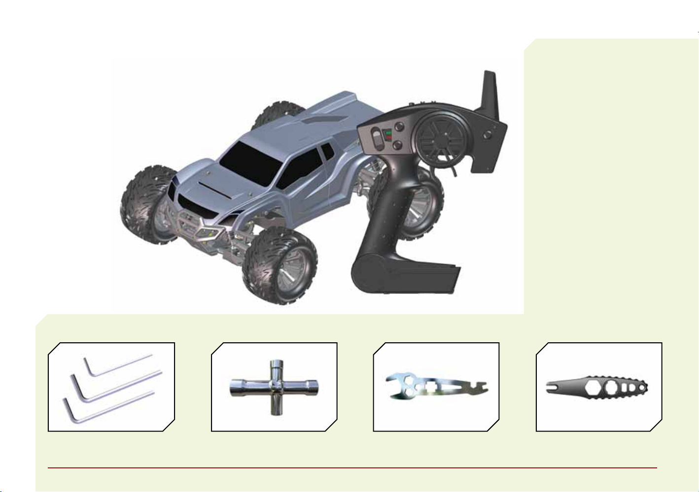
» 1/10-Scale Hälix RTR Monster Truck
» Spektrum™ DX2E 2.4GHz DSM® Radio System
» Dynamite® Fuze™ 70A Waterproof Sensorless Brushless ESC
» Dynamite Fuze 540 4-Pole 3300Kv Sensorless Brushless Motor
» 313WP Standard Waterproof Servo
» 4 AA batteries (for transmitter)
SUPPLIED TOOLS
RECOMMENDED
ACCESSORIES
» Hobby grade knife
» Needle nose pliers
» Side cutting pliers
» Safety goggles
» Soldering iron
Use only Dynamite tools or other
high-quality tools. Use of inexpensive
tools can cause damage to the small
screws and parts used on this type
of model.
» “L” shaped hex wrench
• 1.5mm, 2mm, 2.5mm
» 4-way wrench » Flat Turnbuckle Wrench » Shock Tools
EN
Page 8
SPEKTRUM DX2E RADIO SYSTEM
/ / / / / / / / / / / / / / / / / / / / / / / / / / / / / / / / / / / / / / / / / / / / / / / / / / / / / / / / / / / / / / / / / / / / / / / / / / / / / / / / / / / / / / / / / / / / / / / / / / / / / / / / / / / / / / / / / / / / / / / / / / / / / / / / / / / / / / / / / / / / / / / / / / / / / / / / / / / / / / / / / / / / / / / / / / / / / / / / / / / / / /
For more information on the transmitter, go to www.horizonhobby.com
and click on the support tab for the
Spektrum DX2E to download the
instruction manual.
AVC SENSITIVITY
The ST RATE dial adjusts the sensitivity,
or stability, value in the receiver. If you
increase the sensitivity, the AVC system becomes more sensitive to the vehicle drifting left or right. You would use
maximum sensitivity during high speed
driving or drag racing, when you want
the vehicle to stay in a straight line.
As the sensitivity value increases, the
amount of steering travel decreases.
Turn the ST RATE knob counterclockwise to reduce the sensitivity.
Turn the ST RATE knob clockwise
to increase the sensitivity.
IMPORTANT: The ST RATE knob will
only adjust the sensitivity when the
transmitter is bound to a DSMR™
receiver. When the transmitter is
bound to a DSM, DSM2
Marine receiver, the ST RATE knob
controls the steering dual rate.
or DSM
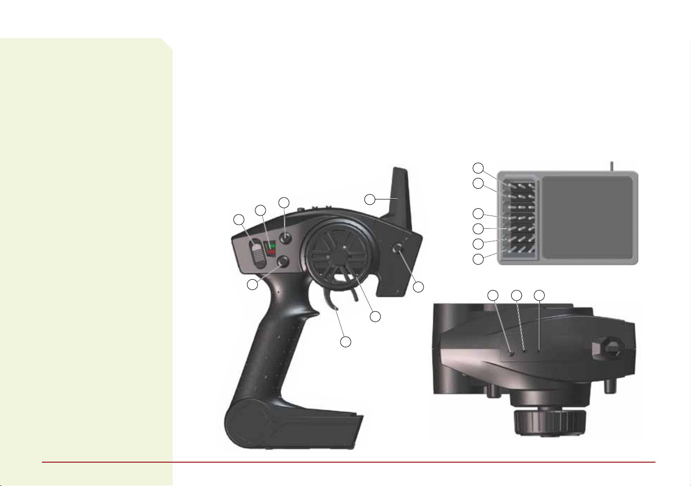
1 Steering Wheel controls direction (left/right) of the model
2 Throttle Trigger controls speed and direction
(forward/brake/reverse) of the model
3 Antenna transmits the signal to the model
4 ON/OFF Switch turns the power ON/OFF for the transmitter
5 Indicator Lights
• Solid green light indicates adequate battery power
• Flashing green light indicates the battery
voltage is critically low. Replace batteries.
6 ST Trim Adjusts the total steering travel
7 TH Trim Adjusts the total throttle travel
8 ST Rate Adjusts the sensitivity value in the receiver
6
5
4
7
3
1
9 BIND Button puts the transmitter into Bind Mode
10 ST. REV reverses the function of the steering
when the wheel is turned left or right
11 TH. REV reverses the function of the speed
control when pulled back or pushed forward
SRS4200 AVC TECHNOLOGY RECEIVER
12 BIND
13 DISABLE
14 AUX 2
15 AUX 1
16 THR
17 STR
8
12
13
14
15
16
17
9 10 11
2
8
Page 9
INSTALLING THE TRANSMITTER BATTERIES
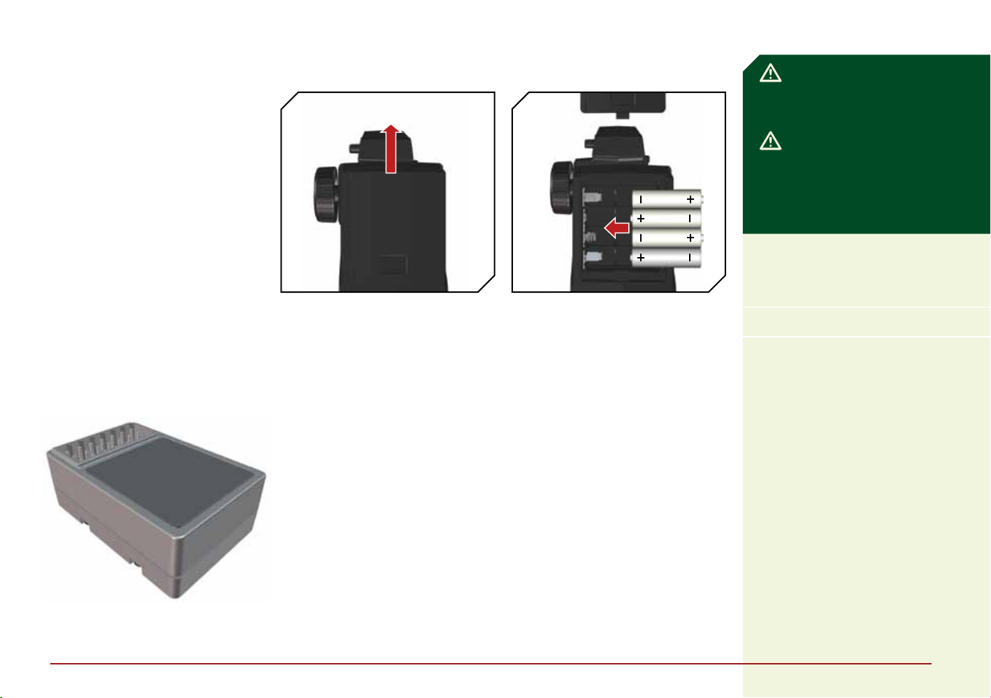
1 Push in the battery cover a small
amount to release the retaining
tab, then remove the cover.
2 Install 4 AA batteries, taking care
to align the battery polarity to the
diagram in the transmitter’s
battery case.
3 Carefully reinstall the battery cover
by aligning the tabs with the slots
on the transmitter.
CAUTION: NEVER remove the
transmitter batteries while the vehicle
is powered ON, as loss of control,
property damage or injury may result.
CAUTION: If using rechargeable
batteries, charge only rechargeable
batteries. Charging non-rechargeable
batteries may cause the batteries to
burst, resulting in injury to persons
and/or damage to property.
CALIBRATING THE RECEIVER
IMPORTANT: You must use digital servos
with the SRS4200 receiver. Using analog
servos will reduce the performance of the
system and may cause analog servos to
overheat.
/ / / / / / / / / / / / / / / / / / / / / / / / / / / / / / / / / / / / / / / / / / / / / / / / / / / / / / / / / / / / / / / / / / / / / / / / / / / / / / /
1 Insert the Bind Plug in the BIND port
on the receiver.
2 Connect a fully charged battery pack
to the ESC.
3 Power on the ESC. The orange LED
flashes, indicating the receiver is
in bind mode.
4 Center the ST TRIM and TH TRIM
dials on the transmitter.
5 Press and hold the BIND button
while powering on the transmitter.
6 Release the BIND button when
the orange LED slowly flashes. The
transmitter and receiver are linked
when the orange LED is solid.
7 Pull the transmitter trigger
to Full Throttle.
8 Push the transmitter trigger to
Full Brake, then return the trigger
to center.
9 Turn the transmitter steering wheel
to Full Right.
10 Turn the transmitter steering
wheel to Full Left, then return
the steering wheel to center.
The orange LED flashes once.
11 Remove the Bind Plug, then power
o the receiver to save the settings.
12 Power o the transmitter.
The Spektrum SRS4200 receiver
features Active Vehicle Control (AVC)
technology that responds similar to
traction control in full-scale vehicles.
In addition to traction control, AVC
technology also increases steering
stability during high speed driving or
while driving over rough terrain. As
you increase the AVC sensitivity, the
system increases steering stability and traction control, similar to
reducing the amount of steering rate
in a computer transmitter. Reducing
the sensitivity value increases the
amount of steering control from the
transmitter. The SRS4200 receiver
also enables you to quickly turn
AVC on or o if you participate
in organized racing.
EN
Page 10

RUN TIME
/ / / / / / / / / / / / / / / / / / / / / / / / / / / / / / / / / / / / / / / / / / / / / / / / / / / / / / / / / / / / / / / / / / / / / / / / / / / / / / / / / / / / / / / /
BEFORE RUNNING YOUR VEHICLE
1 Break in the dierential. While holding
the chassis with only the left rear tire
firmly on the ground, give the vehicle
about 1/8 throttle for 30 seconds.
The right rear tire should spin freely
during this time. Do this with only the
right rear tire firmly on the ground,
allowing the left to spin freely. Repeat
this 2–3 times.
2 Check for free suspension
movement. All suspension arms
and steering components should
move freely. Any binds will cause
the vehicle to handle poorly.
3 Charge the battery.
4 Check the calibration of the ESC.
If recalibration is required, follow
the setup instructions.
5 Adjust the transmitter settings
to your desired configuration.
The largest factor in run time is the
capacity of the battery pack. A larger
mAh rating increases the amount
of run time experienced.
The condition of a battery pack is
also an important factor in both run time
and speed. The battery connectors may
become hot during driving. Batteries will
lose performance and capacity over time.
Driving the vehicle from a stop to
full speed repeatedly will damage the
batteries and electronics over time.
Sudden acceleration will also lead
to shorter run times.
TO IMPROVE RUN TIMES
» Clean and oil bearings often. If bearings
are dirty, they will increase friction and
cause reduced performance.
TUNING, ADJUSTING & MAINTAINING YOUR VEHICLE
» Examine your vehicle on
a regular basis.
» Use a brush to remove dirt and dust.
» Look for damage to the suspension
arms and other molded parts.
» Re-glue the tires to the wheels,
if necessary.
» Clean and oil all wheel bearings.
» Use suitable tools to tighten fasteners.
» Make sure the camber and steering
linkages are not bent. Replace any
bent linkages.
» Adjust the Toe and Camber settings,
if necessary.
» Remove the shocks and inspect them
for damage. Rebuild the shocks if oil
is leaking.
» Inspect electronics and batteries for
exposed wires. Repair exposed wires
with shrink-wrap, or replace the wire.
» Make sure the ESC and receiver are
secure on the chassis. Replace the
double-sided tape, if necessary.
» Power ON the transmitter. If the
green LED is dim or o, replace
the AA batteries in your transmitter.
» Check the spur gear and pinion
gear for wear.
» Keep your vehicle clean and maintained.
» Allow more airflow to the ESC
and motor.
» Change the gearing to a lower ratio.
A lower ratio decreases the operating
temperature of the electronics. Use
a smaller pinion gear or larger spur
gear to lower the gear ratio.
» Use a battery pack with a higher
mAh rating.
DRIVING PRECAUTIONS
» Maintain sight of the vehicle at all times.
» Routinely inspect the vehicle for loose
wheel hardware.
» Routinely inspect the steering assem-
bly for any loose hardware. Driving the
vehicle o-road can cause fasteners
to loosen over time.
» Do not drive the vehicle in tall grass.
Doing so can damage the vehicle
or electronics.
» Stop driving the vehicle when you
notice a lack of power. Driving the
vehicle when the battery is overly
discharged can cause the receiver to
power o. If the receiver loses power,
you will lose control of the vehicle.
» Do not apply forward or reverse throttle
if the vehicle is stuck. Applying throttle
in this instance can damage
the motor or ESC.
» After driving the vehicle, allow the
electronics to cool before driving the
vehicle again. Remove the body of
the vehicle to reduce cooling time.
/ / / / / / / / / / / / / / / / / / / / / / / / / / / / / / / / / / / / / / / / / / / / / / / / / / / / / /
SERVICE/REPAIR
If any problems other than those
covered in this manual arise, please
call the appropriate electronics service
department. Refer to the Warranty and
Service Information section for the appropriate department to contact.
CLEANING
Performance can be hindered if dirt gets
in any of the moving suspension parts.
Use compressed air, a soft paintbrush, or
a toothbrush to remove dust or dirt. Avoid
using solvents or chemicals as they can
actually wash dirt into the bearings or
moving parts, as well as cause damage
to the electronics.
10
Page 11

DYNAMITE 70A WATERPROOF SENSORLESS BRUSHLESS ESC
/ / / / / / / / / / / / / / / / / / / / / / / / / / / / / / / / / / / / / / / / / / / / / / / / / / / /
ESC LED STATUS
» No ESC LEDs will glow when there is
no throttle input from the transmitter.
» The red ESC LED glows when there is
any throttle input from the transmitter.
AUDIBLE WARNING TONES
1 Input voltage: The ESC checks the
input voltage when it is powered ON.
If a voltage problem is detected, the
ESC continuously sounds 2 beeps
with a 1 second pause (xx-xx-xx).
Power OFF the ESC and ensure the
connections are secure and that
the battery power is not too low
for safe operation.
2 Radio connection: The ESC checks
radio signal input when it is powered
ON. If a problem is detected, the ESC
continuously sounds 1 beep with a 2
second pause (x--x--x). Power OFF
the ESC and ensure the radio
system is operating correctly.
ESC CALIBRATION PROCEDURE
Ensure proper ESC function by calibrating the ESC to your transmitter inputs.
1 Power OFF the ESC.
2 Ensure your transmitter is powered
ON, the throttle is not reversed, the
throttle trim is neutral and the
throttle travel range is at 100%.
3 Press the SET button while powering
ON the ESC. Release the button as
soon as the green LED starts to flash.
4 Calibrate the throttle points by
pressing the SET button once
after each step.
• Neutral Leave the throttle
(1 flash) at rest, untouched
• Full throttle Pull the throttle
(2 flashes) fully back
• Full brake/ Push the throttle
reverse fully forward
(3 flashes)
5 The motor vibrates for 3 seconds
after the last step is completed.
ESC FUNCTIONS AND MODES
The ESC includes programming
options so you can adjust the way your
vehicle performs. Refer to the included
settings table to adjust the ESC for
your driving conditions.
ESC PROGRAMMING PROCEDURE
Programming is accomplished using
the SET button on the ON/OFF switch.
Programming the ESC
1 Connect a fully charged battery
to the ESC.
2 Power ON the ESC.
3 Hold the SET button for 1 second
until the green LED blinks, then
release the SET button to enter
programming mode.
4 Press and release the SET button
as needed to get to the desired
menu option (the green LED will
blink corresponding to the menu
item number).
5 When at the desired menu item,
hold the SET button for 3 seconds
until the red LED blinks.
6 Press the SET button to move among
the settings based on how many
times the red LED blinks (Refer
to the table for more information).
7 Save the setting by holding the
SET button for 3 seconds.
8 Power OFF the ESC and repeat
the instructions above to change
other settings.
Tip: If desired, the ESC programming
can be returned to default settings
by powering ON the ESC and holding
the SET button for 5 seconds.
TECHNICAL SPECIFICATIONS
Type
Sensorless/Waterproof
Constant/Peak
70A/290A
Resistance
0.0012 Ohms
Function
Forward Only with Brake
Forward/Reverse with Brake
Operation
Proportional forward,
proportional reverse with braking delay
Battery Type/ Input Voltage
2–3 cell Li-Po/Li-Fe or
4–9 cell Ni-MH/Ni-Cd
BEC Output
6V/3A
Overload Protection
Thermal
Dimensions (LxWxH)
1.24 x 1.08 x 1.30 in
(31.5 x 27.5 x 33mm)
Weight
2.61 oz (74 g) with wires
NOTICE: Always disconnect the
battery from the ESC when you have
finished operating your vehicle. The
ESC’s switch only controls power
to the receiver and servos. The ESC
will continue to draw current when
connected to the battery, resulting
in possible damage to the battery
through over-discharge.
EN
Page 12

/ / / / / / / / / / / / / / / / / / / / / / / / / / / / / / / / / / / / / / / / / / / / / / / / / / / / / / / / / / / / / / / / / / / / / / / / / / / / / / / / / / / / / / / / / / / / / / / / / / / / /
Default Settings
PROGRAMMABLE ITEMS PROGRAMMABLE VALUE
1 Running Mode Forward Only
2 Drag Brake Force 0% 5% 10% 15% 20% 25% 30% 40%
3 Low Voltage Cuto
Threshold
4 Start Mode (Punch) Level 1 Level 2 Level 3 Level 4
5 Max Brake Force 25% 50% 75% 100%
DESCRIPTIONS
1 Running Mode
• Forward Only with Brake
Intended for competition use, this
mode allows only forward and
brake controls.
• Forward/Reverse with Brake
This mode is the basic all-around
mode, allowing forward, reverse
and brake controls. To engage
reverse while moving forward,
apply the brake until the vehicle
has come to a complete stop.
Release the brake, then apply the
brake again. While braking or in
reverse, engaging the throttle will
result in the vehicle immediately
accelerating forward.
1 2 3 4 5 6 7 8
with Brake
nonprotection
Forward/Reverse
with Brake
2.6V/Cell 2.8V/
Cell
2 Drag Brake Force
Adjusts the amount of brake auto-
matically applied when the throttle
is returned to neutral. This simulates the engine braking eect of a
full-scale vehicle, allowing improved
turn-in and your vehicle’s general
response to controls.
3 Low Voltage Cuto Threshold
This function helps to prevent battery
over-discharge. The ESC continuously
monitors the battery’s voltage. If the
voltage falls below the voltage threshold for 2 seconds, the output power
shuts o and the red LED flashes
twice repeatedly.
The cuto threshold calculation is
based on individual Li-Po cell voltage.
For Ni-MH batteries, if the voltage
battery pack is higher than 9.0V, it will
be treated as a 3-cell Li-Po battery
pack; if it is lower than 9.0V, it will be
treated as a 2-cell Li-Po battery pack.
3.0V/
Cell
3.2V/
Cell
Example: for a 8.0V Ni-MH battery
pack used with a 2.6V/cell threshold,
it will be treated as a 2-cell Li-Po battery pack and the low-voltage cuto
threshold will be 5.2V (2.6x2=5.2).
Using the optional Digital Program
Box (DYN3748, sold separately), you
can adjust the custom values for the
cuto threshold. Unlike the preset
values, custom cuto values are
for the total battery voltage, not
individual cell voltage.
4 Start Mode (Punch)
Sets the initial throttle punch when
the car accelerates. Level 1 gives a
very soft initial acceleration and level
4 gives a stronger initial acceleration.
5 Max Brake Force
Adjusts the maximum braking force.
A higher value provides stronger
braking, but can also cause the
wheels to lock, resulting in loss
of control of the car.
3.4V/
Cell
12
Page 13
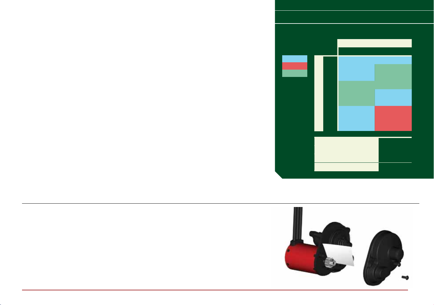
DYNAMITE FUZE 540 4-POLE 3300KV SENSORLESS BRUSHLESS MOTOR
GEAR CHART
/ / / / / / / / / / / / / / / / / / / / / / / / / / / /
GEARING
Your vehicle has been equipped with the
optimal gearing for the stock platform. It
oers an ideal balance between speed,
power and eciency. Should you decide
to customize your vehicle with optional
batteries or motors, it may be necessary
for you to change the pinion or spur gear.
Installing a pinion gear with less teeth or
a spur gear with more teeth will provide
greater torque but will reduce top speed.
Likewise, a pinion gear with more teeth or
a spur gear with fewer teeth will reduce
torque and increase top speed. Care
should be taken when installing larger
pinion gears as this can “overgear” the
vehicle, resulting in overheating of the
motor and ESC.When testing dierent gearing options, pay close attention to the temperature of the motor
and speed control to ensure you are
operating within the temperature range
of the components.The motor or ESC
should never be so hot that it cannot be
touched.If temperatures are too hot,
a dierent gearing combination with a
lower pinion gear and/or higher spur gear
is suggested.
SETTING THE GEAR MESH
The gear mesh has already been set at
the factory, and setting it is only necessary when changing motors or gears.
Proper gear mesh (how gear teeth meet)
is important to the performance of the
vehicle. When the gear mesh is too loose,
the spur gear could be damaged by the
pinion gear of the motor. If the mesh is
too tight, speed could be limited and the
motor and ESC will overheat.
PRECAUTIONS
» Never touch moving parts.
» Never disassemble while the batteries are installed.
» Always let parts cool before touching.
ADJUSTING THE SLIPPER
Turn the 5mm adjustment nut clockwise (to the right) to reduce
the slip or counterclockwise (to the left) to increase the slip.
CHANGING THE PINION GEAR/GEAR RATIO
Your vehicle comes with the 20T pinion gear. To change to another pinion gear (sold separately), follow the directions below.
1 Unscrew the 3 screws holding the gear cover/motor mount
in place.
2 Remove the motor gear cover.
3 Remove the pinion gear.
4 Remove the screws holding the motor and move to the
appropriate holes (marked with the number of teeth on
the pinion) and reinstall the screws.
5 Place the new pinion gear on the motor shaft.
6 Reinstall the gear cover.
To set the gear mesh, screw the motor into the corresponding
marked set of holes. For example, with a 20T pinion, the motor
screws must be screwed into the holes labeled “20”.
FINAL DRIVE RATIOS
Marginal
Thermo
OK
EXAMPLE
16T 14.52 14.52
17T 13.66 13.66
18T 12.91 12.91
19T 12.23 12.23
20T 11.61 11.61
PINION
21T 11.06 11.06
22T 10.56 10.56
23T 10.10 10.10
24T 9.68 9.68
INTERNAL GEAR RATIO 2.67
SPUR 87
PINION 20
FINAL DRIVE RATIO 11.61
FINAL DRIVE RATIO
2S 3S
EN
Page 14

CHANGING THE TRAVEL ADJUST SETTINGS
/ / / / / / / / / / / / / / / / / / / / / / / / / / / / / / / / / / / / / / / / / / / / / / / / / / / / / / / / / / / / / /
The minimum Travel is 75%,
and the Maximum travel is 150%.
IMPORTANT: If the travel is changed
on the DX2E, you must rebind and
calibrate the SRS4200.
1 Hold the trigger in the full brake position while powering
on the transmitter. The LED flashes rapidly, indicating the
programming mode is active.
2 Throttle End Point Continue holding full throttle. Turn the
TH TRIM knob to adjust the full throttle end point.
3 Brake End Point Hold the trigger in the full brake position.
Turn the TH TRIM knob to adjust the full brake end point.
Return the trigger to the center position.
DISABLING THE STABILITY ASSIST FUNCTION
If you participate in organized racing,
you may be required to turn Stability
Assist o.
IMPORTANT: You must calibrate
the receiver each time it is placed
in bind mode.
To activate AVC, see the steps in
“Calibrating the Receiver”.
1 Insert a Bind Plug in the BIND port on the receiver.
2 Insert a second Bing Plug in the DISABLE port on
the receiver.
3 Connect a fully charged battery pack to the ESC.
4 Power on the ESC. The orange LED flashes, indicating
the receiver is in bind mode.
5 Center the ST TRIM and TH TRIM dials on the transmitter.
6 Press and hold the BIND button while powering on
the transmitter.
7 Release the BIND button when the orange LED slowly
flashes. The transmitter and receiver are linked when
the orange LED is solid.
4 Left Steering End Point Hold the steering wheel in the
full left position. Turn the ST TRIM knob to adjust the left
end point.
5 Right Steering End Point Hold the steering wheel in the full
right position. Turn the ST TRIM knob to adjust the right end
point. Return the steering wheel to the center position.
6 Power o the transmitter to save the travel adjust settings.
/ / / / / / / / / / / / / / / / / / / / / / / / / / / / / / / / / / / / / / / / / / / / / / / / / / / / / / / / / / / /
8 Pull the transmitter trigger to Full Throttle.
9 Push the transmitter trigger to Full Brake, then return
the trigger to center.
10 Turn the transmitter steering wheel to Full Right.
11 Turn the transmitter steering wheel to Full Left, then return
the steering wheel to center. The orange LED flashes once.
12 Remove the Bind Plugs, then power o the receiver to
save the settings.
13 Power o the transmitter.
14
Page 15

TROUBLESHOOTING GUIDE
PROBLEM POSSIBLE CAUSE SOLUTION
Vehicle does
not operate
» Battery not charged or connected
» ESC switch not ON
» Transmitter not ON or low battery
Motor runs but
rear wheels
don’t move
» Pinion not meshing with spur gear
» Pinion spinning on motor shaft
» Slipper too loose
» Transmission gears stripped
» Drive pin broken
Steering does
not work
» Servo plug not in receiver properly
» Servo gears or motor damaged
/ / / / / / / / / / / / / / / / / / / / / / / / / / / / / / / / / / / / / / / / / / / / / / / / / / / / / / / / / / / / / / / / / / / / / / / / / / / / / / / /
» Charge battery/connect
» Turn ON ESC switch
» Turn ON/replace batteries
» Adjust pinion/spur mesh
» Replace pinion gear on motor
» Check and adjust slipper
» Replace transmission gears
» Check and replace drive pin
» Check if connected/all the way
» Replace or repair servo
Won’t turn in
one direction
Motor does
not run
ESC gets hot
Poor run time
and/or sluggish
acceleration
Poor range
and/or glitching
Slipper won’t
adjust
» Servo gears damaged » Replace servo
» Motor plugs loose
» Motor wire broken
» ESC damaged
» Motor over-geared
» Driveline bound up
» Battery not fully charged
» Charger not allowing full charge
» Slipper slipping too much
» Motor worn out
» Driveline bound up
» Transmitter batteries low
» Vehicle battery low
» Loose plugs or wires
» Drive pin missing in shaft
» Spur gear face worn out
» Plug in completely
» Repair or replace as needed
» Contact Horizon Hobby Product Support
» Use smaller pinion or larger spur gear on motor
» Check wheels, suspension and transmission for binding
» Recharge battery
» Try another charger
» Check/adjust slipper
» Replace motor
» Check wheels, transmission for binding
» Check and replace
» Recharge or replace
» Check all wire connections and plugs
» Replace drive pin
» Replace spur gear and adjust slipper
EN
Page 16

LIMITED WARRANTY
/ / / / / / / / / / / / / / / / / / / / / / / / / / / / / / / / / / / / / / / / / / / / / / / / / / / / / / / / / / / / / / / / / / / / / / / / / / / / / / / / / / / / / / / / / / / / / / / / / / / / / / / / / / / / / / / / / / / / / / / / / / / / / / / / / / / / / / / / / / / / / / / / / / / / / / / / / / / / / / / / / / / / / / / / / / / / / / / / / / / / / / / / / / / / / / / / /
WHAT THIS WARRANTY COVERS
Horizon Hobby, Inc., (Horizon) warrants to the original
purchaser that the product purchased (the “Product”)
will be free from defects in materials and workmanship
at the date of purchase.
WHAT IS NOT COVERED
This warranty is not transferable and does not cover (i)
cosmetic damage, (ii) damage due to acts of God, accident, misuse, abuse, negligence, commercial use, or due
to improper use, installation, operation or maintenance,
(iii) modification of or to any part of the Product, (iv) attempted service by anyone other than a Horizon Hobby
authorized service center, (v) Product not purchased
from an authorized Horizon dealer, or (vi) Product not
compliant with applicable technical regulations.
OTHER THAN THE EXPRESS WARRANTY ABOVE,
HORIZON MAKES NO OTHER WARRANTY OR REPRESENTATION, AND HEREBY DISCLAIMS ANY AND ALL IMPLIED WARRANTIES, INCLUDING, WITHOUT LIMITATION,
THE IMPLIED WARRANTIES OF NON-INFRINGEMENT,
MERCHANTABILITY AND FITNESS FOR A PARTICULAR
PURPOSE. THE PURCHASER ACKNOWLEDGES THAT
THEY ALONE HAVE DETERMINED THAT THE PRODUCT
WILL SUITABLY MEET THE REQUIREMENTS OF THE
PURCHASER’S INTENDED USE.
PURCHASER’S REMEDY
Horizon’s sole obligation and purchaser’s sole and
exclusive remedy shall be that Horizon will, at its option,
either (i) service, or (ii) replace, any Product determined
by Horizon to be defective. Horizon reserves the right
to inspect any and all Product(s) involved in a warranty
claim. Service or replacement decisions are at the sole
discretion of Horizon. Proof of purchase is required for
all warranty claims. SERVICE OR REPLACEMENT
AS PROVIDED UNDER THIS WARRANTY IS THE
PURCHASER’S SOLE AND EXCLUSIVE REMEDY.
LIMITATION OF LIABILITY
HORIZON SHALL NOT BE LIABLE FOR SPECIAL, INDIRECT, INCIDENTAL OR CONSEQUENTIAL DAMAGES,
LOSS OF PROFITS OR PRODUCTION OR COMMERCIAL
LOSS IN ANY WAY, REGARDLESS OF WHETHER SUCH
CLAIM IS BASED IN CONTRACT, WARRANTY, TORT, NEGLIGENCE, STRICT LIABILITY OR ANY OTHER THEORY OF
LIABILITY, EVEN IF HORIZON HAS BEEN ADVISED OF
THE POSSIBILITY OF SUCH DAMAGES. Further, in no
event shall the liability of Horizon exceed the individual
price of the Product on which liability is asserted. As
Horizon has no control over use, setup, final assembly,
modification or misuse, no liability shall be assumed nor
accepted for any resulting damage or injury. By the act
of use, setup or assembly, the user accepts all resulting
liability. If you as the purchaser or user are not prepared
to accept the liability associated with the use of the
Product, purchaser is advised to return the Product
immediately in new and unused condition to the place
of purchase.
LAW
These terms are governed by Illinois law (without regard
to conflict of law principals). This warranty gives you
specific legal rights, and you may also have other rights
which vary from state to state. Horizon reserves the
right to change or modify this warranty at any time
without notice.
WARRANTY SERVICES
QUESTIONS, ASSISTANCE, AND SERVICES
Your local hobby store and/or place of purchase cannot
provide warranty support or service. Once assembly,
setup or use of the Product has been started, you
must contact your local distributor or Horizon directly.
This will enable Horizon to better answer your questions and service you in the event that you may need
any assistance. For questions or assistance, please
visit our website at www.horizonhobby.com, submit a
Product Support Inquiry, or call the toll free telephone
number referenced in the Warranty and Service Contact
Information section to speak with a Product Support
representative.
INSPECTION OR SERVICES
If this Product needs to be inspected or serviced and is
compliant in the country you live and use the Product in,
please use the Horizon Online Service Request submission process found on our website or call Horizon to
obtain a Return Merchandise Authorization (RMA) number. Pack the Product securely using a shipping carton.
Please note that original boxes may be included, but are
not designed to withstand the rigors of shipping without
additional protection. Ship via a carrier that provides
tracking and insurance for lost or damaged parcels,
as Horizon is not responsible for merchandise until it
arrives and is accepted at our facility. An Online Service
Request is available at http://www.horizonhobby.com/
content/_service-center_render-service-center. If you
do not have internet access, please contact Horizon
Product Support to obtain a RMA number along with instructions for submitting your product for service. When
calling Horizon, you will be asked to provide your complete name, street address, email address and phone
number where you can be reached during business
hours. When sending product into Horizon, please include your RMA number, a list of the included items, and
a brief summary of the problem. A copy of your original
sales receipt must be included for warranty consideration. Be sure your name, address, and RMA number are
clearly written on the outside of the shipping carton.
16
Page 17

NOTICE: Do not ship Li-Po batteries to Horizon. If
you have any issue with a LiPo battery, please contact the appropriate Horizon Product Support oce.
WARRANTY REQUIREMENTS
For Warranty consideration, you must include your
original sales receipt verifying the proof-of-purchase
date. Provided warranty conditions have been met,
your Product will be serviced or replaced free of
charge. Service or replacement decisions are
at the sole discretion of Horizon.
NON-WARRANTY SERVICE
Should your service not be covered by warranty,
service will be completed and payment will be required
without notification or estimate of the expense unless
the expense exceeds 50% of the retail purchase cost.
By submitting the item for service you are agreeing
to payment of the service without notification. Service
estimates are available upon request. You must include
this request with your item submitted for service.
Non-warranty service estimates will be billed a minimum of 1/2 hour of labor. In addition you will be billed
for return freight. Horizon accepts money orders and
cashier’s checks, as well as Visa, MasterCard, American
Express, and Discover cards. By submitting any item
to Horizon for service, you are agreeing to Horizon’s
Terms and Conditions found on our website http://www.
horizonhobby.com/content/_service-center_renderservice-center.
WARRANTY AND SERVICE CONTACT INFORMATION
COUNTRY OF
PURCHASE
United States
of America
United
Kingdom
Germany Horizon Technischer
China Service/Parts/Sales:
HORIZON HOBBY CONTACT INFORMATION ADDRESS
Horizon Service Center
(Repairs and Repair Requests)
Horizon Product Support
(Product Technical Assistance)
Sales [email protected]
Service/Parts/Sales:
Horizon Hobby Limited
Service
Sales: Horizon Hobby
GmbH
Horizon Hobby - China
servicecenter.horizonhobby.com/
RequestForm/
www.quickbase.com/db/
bghj7ey8c?a=GenNewRecord
888-959-2306
888-959-2306
[email protected]
+44 (0) 1279 641 097
[email protected]
+49 (0) 4121 2655 100
+33 (0) 1 60 18 34 90
[email protected]
+86 (021) 5180 9868
4105 Fieldstone Rd
Champaign, Illinois
61822 USA
Units 1-4 Ployters Rd
Staple Tye
Harlow, Essex
CM18 7NS
United Kingdom
Christian-Junge-Straße 1
25337 Elmshorn
11 Rue Georges Charpak
77127 Lieusaint, France
Room 506
No. 97 Changshou Rd.
Shanghai, China 200060
ATTENTION: Horizon service is limited to Product
compliant in the country of use and ownership. If
received, a non-compliant Product will not be serviced. Further, the sender will be responsible for arranging return shipment of the un-serviced Product,
through a carrier of the sender’s choice and at the
sender’s expense. Horizon will hold non-compliant
Product for a period of 60 days from notification,
after which it will be discarded.
EN
Page 18
FCC INFORMATION
/ / / / / / / / / / / / / / / / / / / / / / / / / / / / / / / /
COMPLIANCE INFORMATION FOR THE EUROPEAN UNION
/ /
This device complies with part 15 of the
FCC rules. Operation is subject to the
following two conditions: (1) This device
may not cause harmful interference,
and (2) this device must accept any
interference received, including
interference that may cause
undesired operation.
CAUTION: Changes or
modifications not expressly
approved by the party responsible
for compliance could void the user’s
authority to operate the equipment.
This product contains a radio
transmitter with wireless technology
which has been tested and found to
be compliant with the applicable
regulations governing a radio
transmitter in the 2.400GHz to
2.4835GHz frequency range.
IC INFORMATION
This device complies with Industry Canada licence-exempt RSS standard(s).
Operation is subject to the following two conditions: (1) this device may not
cause interference, and (2) this device must accept any interference,
including interference that may cause undesired operation of the device.
/ / / / / / / / / / / / / / / / / / / / / / / / / / / / / / / / /
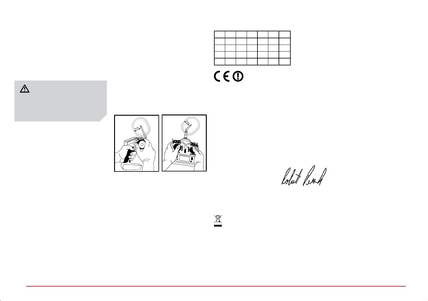
ANTENNA SEPARATION DISTANCE
When operating your Spektrum
transmitter, please be sure to maintain
a separation distance of at least 5 cm
between your body (excluding fingers,
hands, wrists, ankles and feet) and the
antenna to meet RF exposure safety
requirements as determined by
FCC regulations.
The following illustrations show the
approximate 5 cm RF exposure area
and typical hand placement when
operating your Spektrum transmitter.
AT BE BG CZ CY DE DK
EE ES FI FR GR HR HU
IE IT LT LU LV MT NL
PL PT RO SE SI SK UK
IS LI NO CH
DECLARATION OF CONFORMITY
(in accordance with ISO/IEC 17050-1)
No. HH2013092903
Product(s): VTR Hälix 4WD Monster Truck
Item Number(s): VTR03003
Equipment class: 2
The object of declaration described above is in conformity with the requirements
of the specifications listed below, following the provisions of the European R&TTE
directive 1999/5/EC and EMC Directive 2004/108/EC:
EN 300-328 V1.7.1: 2006
EN301 489-1 V1.9.2: 2012
EN301 489-17 V2.1.1: 2009
EN60950-1:2006+A11:2009+A1:2010+A12: 2011
EN55022:2010 + AC:2011
EN55024:2010
Signed for and on behalf of:
Horizon Hobby, Inc.
Champaign, IL USA
September 29, 2013
(Spektrum DX2E transmitter and SRS4200WP receiver included)
Robert Peak
Chief Financial Ocer
Horizon Hobby, Inc.
INSTRUCTIONS FOR DISPOSAL OF
WEEE BY USERS IN THE EUROPEAN UNION
This product must not be disposed of with other waste. Instead, it is the user’s
responsibility to dispose of their waste equipment by handing it over to a designated
collection point for the recycling of waste electrical and electronic equipment. The
separate collection and recycling of your waste equipment at the time of disposal
will help to conserve natural resources and ensure that it is recycled in a manner that
protects human health and the environment. For more information about where you
can drop o your waste equipment for recycling, please contact your local city oce,
your household waste disposal service or where you purchased the product.
18
 Loading...