

Page 1

VA TECH ELIN EBG Elektronik
Operating and Mounting instructions
The Power Drives Company
>pDRIVE< CX profi
Page 2

The requirements for a successfull commissioning are a correct selection of the unit, projection and
mounting. In case of further questions, please contact the supplier or call the manufacturer of the unit
directly.
Capacitor discharge !
Before any work on or in the unit, disconnect from the mains and wait at least 5 minutes until the
D.C.link capacitors have been fully discharged. Check that the device is no longer alive by measuring
the voltage at the D.C.link capacitor.
Automatic restart !
In case of certain parameter adjustments it may happen that the frequency inverter starts up
automatically after switching on the mains again. You have to guarantee, that no person and no other
equipment is in danger.
Commissioning and service !
Works on or in the unit must only be undertaken by properly qualified staff in full compliance of the
appropriate instructions and pertinent regulations. Note that a fault may cause potential-free contacts
and/or PCBs to carry mains potential. To avoid any risk to humans, obey the regulations concering
”Work on Live Equipment” explicitly.
Delivery conditions:
Our deliveries and services are based on the ”General Terms of Delivery of the Austrian Electrical
Industries” latest edition.
Specifications in this instruction:
We are constantly striving to improve our products and adapt them to the latest state of technical
development. We therefore reserve the right to modify the specifications given in this instruction at any
time, particulary those refering to measures and dimensions. All planning hints and connecting samples
are non-binding suggestions, for which we are unable to assume any liability, particulary since the
regulations to be complied with depend on the type and location of the plant and on the use of the
instruments.
Regulations:
It is the users responsibility to ensure that the instrument and its component parts are used in
compliance with applicable regulations. It is not permitted to use these instruments in residential areas
without special measures to supress radio frequency interferences.
Patent and Trade Marks:
Please note that we do not guarantee any connections, instruments or processes described herein to be
free from patent or trademark right of third parties.
Keep this instruction near the unit to hand !
Safety instructions
General information, note exactly !
Page 3

Operating & Mounting instructions – 8 074 143.03/03 – Page 1
Operating and Mounting the Frequency inverter
>pDRIVE< CX profi
11...37 kW, 3 AC 380...480 V
Topic Page
Operating 3
Parameters 17
Displays 61
Projecting 67
Mounting 73
Connection 77
Options 90
Start-up Log Appendix A
This manual includes the topics operating, description of parameters and displays,
projecting, mounting, connection and options.
Regulations for the observance of the CE-directive and the new Power-Drive-Standard
(EN 61800-3) are described in chapter “CE Marking”.
In case of damage or incomplete delivery, please inform the supplier or the insurance
company.
The manufacturer declines responsibilitiy for faults occuring during transport or
unpacking.
OperatingParameters
DisplaysProjecting
MountingConnection
Options
Page 4

Operating & Mounting instructions – 8 074 143.03/03 – Page 2
Configurable
LED display
STOP/RESET button
to stop the motor or
confirm error
POTENTIOMETER
to adjust the frequency.
The LED lights up as
soon as the frequency
can be set using the
potentiometer
STR button
to save new data and
parameter settings
UP/DOWN buttons
for editing data and for
parametrization
FUNC button
to switch between
display level, 1st and
2nd control level
Operating using the control panel built-in
Description of the control panel
RUN button
starts the inverter when it
is not controlled via the
terminal strip
Quick navigation and adjustment of parameters
The method described above is used for quick selection of parameters. Also the adjustmend of
parameters can be handled in this way.
Page 5
Operating & Mounting instructions – 8 074 143.03/03 – Page 3
Operating
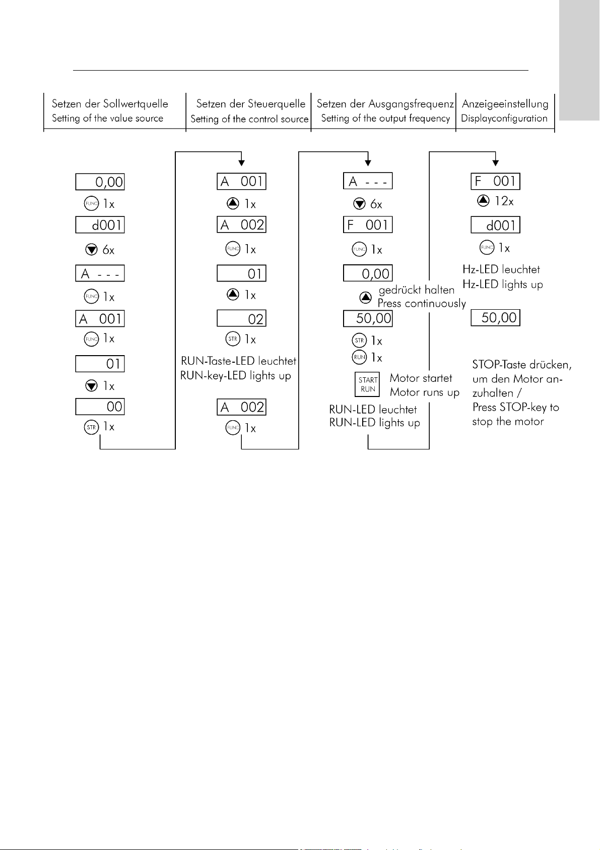
Example of programming to set the frequency and to start the inverter
Page 6

Operating & Mounting instructions – 8 074 143.03/03 – Page 4
Power-LED:
lights up when the inverter is connected to mains supply, that means there is a voltage.
Alarm-LED:
lights up in case of a trip at the inverter.
Hz-LED:
indicates that the value of the display shows frequency in hertz.
V
-LED:
lights up if the value of the display is the voltage in volts or the power in kW.
A
-LED:
indicates that the value of the display shows motor current in amperes or the power in kW.
%-LED:
lights up if the value of the display shows an parameter in %.
PO
TENTIOMETER-LED:
lights up if parameter A001 is set to 00; that means the frequency reference value is defined on the
control panel by the potentiometer.
RUN-button-LED:
indicates that the motor can be started at any time by pressing the RUN button.
Flashes as soon as parameter A002 is set to 02.
PRG
-LED:
lights up as soon as a parameter of the 2nd control level or one of parameters d001 or F001 to
F004 is called.
Lights up if you try to change a parameter during an alarm message.
RUN-LED:
lights up as soon as the motor exceeds the start-up frequency or runs up.
LEDs on the control panel
RUN-LED
PRG-LED
RUN-button
LED
Power-LED
Alarm-LED
Hz-LED
V-LED
A-LED
POTI-LED
%-LED
Page 7

Operating & Mounting instructions – 8 074 143.03/03 – Page 5
Operating
Overview of control levels
Page 8

Operating & Mounting instructions – 8 074 143.03/03 – Page 6
Changing the indication of the LED display:
1.) Switch to the 1st user level using the FUNC button.
2.) Use the UP/DOWN buttons to select the required display.
3.) Press the STR button to confirm the selection and to return to the display level.
Changing parameter settings on the 1st control level:
1.) Switch to the 1st control level using the FUNC button.
2.) Use the UP/DOWN buttons to select the required parameter.
3.) Press the FUNC button to switch to setting mode.
4.) Use the UP/DOWN buttons to enter the new setting.
5.) Press the STR button to confirm, save and return to 1st control level. Press the FUNC button to
return to the 1st control level without saving.
6.) Select the required display (e.g. d001) and press the FUNC button to confirm.
Changing parameter settings on the 2nd control level:
1.) Switch to the 1st control level using the FUNC button.
2.) Use the UP/DOWN buttons to select the required parameter group A, b, C, H or P.
3.) Press the FUNC button to enter the selected parameter group (2nd control level).
4.) Use the UP/DOWN buttons to select the required parameter.
5.) Press the FUNC button to switch to setting mode.
6.) Use the UP/DOWN buttons to enter the new setting.
7.) Press the STR button to confirm, save and return to 2nd control level. Press the FUNC botton to
return to 2nd control level without saving.
8.) Press the FUNC button to return to the 1st control level.
9.) Select the required display (e.g. d001) and press the STR button to confirm.
Page 9

Overview of parameters
The following overviwe shows all parameters arranged according to their functions.
Display actual values Factory See
Parameter name Adjusting range default page
d001 Output frequency read only - 16
d002 Output current read only - 16
d003 Direction of rotation read only - 16
d004 PID controller feedback read only - 16
d005 Condition of digital inputs read only - 17
d006 Condition of digital outputs read only - 17
d007 Output frequency scaled read only - 17
d013 Output voltage read only - 17
d014 Output power read only - 17
d016 Operating hours motor read only - 17
d017 Operating hours inverter read only - 17
Base settings Factory See
Parameter name Adjusting range default page
A003 Base frequency 30...400 Hz 50 Hz 18
A004 Maximum frequency 30...400 Hz 50 Hz 18
F002 1st Acceleration ramp 0,01...3600 s 30 s 18
F003 1st Deceleration ramp 0,01...3600 s 30 s 18
F001 Output frequency 0,00...400,0 Hz - 18
A020 Internal pre-set speed if A001=02 0,00...400,0 Hz 0,00 Hz 18
A001 Method of speed command 00 to 05 01 19
A002 Method of run command 01 to 05 01 19
Operating & Mounting instructions – 8 074 143.03/03 – Page 7
Operating
Page 10
Operating & Mounting instructions – 8 074 143.03/03 – Page 8
Analog inputs Factory See
Parameter name Adjusting range default page
A011 External frequency start O (0...10V) 0,00...400,0 Hz 0,00 Hz 19
A101 External frequency start OI (4...20mA) 0,00...400,0 Hz 0,00 Hz 19
A111 External frequency start O2 (-10...+10V) -400,0...+400,0 Hz 0,00 Hz 19
A012 External frequency end O (0...10V) 0,00...400,0 Hz 0,00 Hz 19
A102 External frequency end OI (4...20mA) 0,00...400,0 Hz 0,00 Hz 19
A112 External frequency end O2 (-10...+10V) -400,0...400,0 Hz 0,00 Hz 19
A013 Analog signal ref. for Start O (0...10V) 0...100 % 0 % 19
A103 Analog signal ref. for Start OI (4...20mA) 0...100 % 0 % 19
A113 Analog signal ref. for Start O2 (-10...+10V) -100...+100 % -100 % 19
A014 Analog signal reference for end O (0...10V) 0...100 % 100 % 20
A104 Analog signal ref. for end OI (4...20mA) 0...100 % 100 % 20
A114 Analog signal ref. for end O2 (-10...+10V) -100...+100 % 100 % 20
A015 External frequency start pattern O (0...10V) 00 or 01 01 20
A105 Ext. frequency start pattern OI (4...20mA) 00 or 01 01 20
A005 AT Terminal selection 00 or 01 01 21
A006 O2 Control selection 00 to 02 00 21
A016 Time constant for analog signals 1...30 30 21
C081
Adjustment 0...10 V input 0...9999 Default 22
C082
Adjustment 4...20 mA input 0...9999 Default 22
C083
Adjustment -10...+10 V input 0...9999 Default 22
C121
Offset-adjustment 0...10 V input 0...9999 Default 22
C122
Offset-adjustment 4...20 mA input 0...9999 Default 22
C123
Offset-adjustment -10...+10 V input 0...9999 Default 22
Multispeeds Factory See
Parameter name Adjusting range default page
A019 Multi speed selection 00 or 01 00 22
A021 Multi speed 1 0,00...400,0 Hz 0,00 Hz 22
A022 Multi speed 2 0,00...400,0 Hz 0,00 Hz 22
A023 Multi speed 3 0,00...400,0 Hz 0,00 Hz 22
A024 Multi speed 4 0,00...400,0 Hz 0,00 Hz 22
A025 Multi speed 5 0,00...400,0 Hz 0,00 Hz 22
A026 Multi speed 6 0,00...400,0 Hz 0,00 Hz 22
A027 Multi speed 7 0,00...400,0 Hz 0,00 Hz 22
A028 Multi speed 8 0,00...400,0 Hz 0,00 Hz 22
A029 Multi speed 9 0,00...400,0 Hz 0,00 Hz 22
A030 Multi speed 10 0,00...400,0 Hz 0,00 Hz 22
A031 Multi speed 11 0,00...400,0 Hz 0,00 Hz 22
A032 Multi speed 12 0,00...400,0 Hz 0,00 Hz 22
A033 Multi speed 13 0,00...400,0 Hz 0,00 Hz 22
A034 Multi speed 14 0,00...400,0 Hz 0,00 Hz 22
A035 Multi speed 15 0,00...400,0 Hz 0,00 Hz 22
A038 Jogging frequency 0,00...9,99 Hz 1,00 Hz 23
A039 Stop mode of jog function 00 to 05 00 23
Page 11

Operating & Mounting instructions – 8 074 143.03/03 – Page 9
Operating
V/f characteristic Factory See
Parameter name Adjusting range default page
A041 Torque boost method selection 00 or 01 00 24
A042 Manual torque boost setting 0,0...20,0 % 1,0 % 24
A043 Manual torque boost frequency point 0,0...50,0 % 5,0 % 24
A044 V/f characteristic setting 00 to 02 00 24
A045
Voltage gain setting 20...100 % 100 % 25
b036
Start reduced voltage selection 00 to 06 00 25
b100
Free adjustable V/f: frequency 1 0...b102 0 Hz 25
b101
Free adjustable V/f: voltage 1 0,0...800,0 V 0,0 V 25
b102
Free adjustable V/f: frequency 2 0...b104 0 Hz 25
b103
Free adjustable V/f: voltage 2 0,0...800,0 V 0,0 V 25
b104
Free adjustable V/f: frequency 3 0...b106 0 Hz 25
b105
Free adjustable V/f: voltage 3 0,0...800,0 V 0,0 V 25
b106
Free adjustable V/f: frequency 4 0...b108 0 Hz 25
b107
Free adjustable V/f: voltage 4 0,0...800,0 V 0,0 V 25
b108
Free adjustable V/f: frequency 5 0...b110 0 Hz 25
b109
Free adjustable V/f: voltage 5 0,0...800,0 V 0,0 V 25
b110
Free adjustable V/f: frequency 6 0...b112 0 Hz 25
b111
Free adjustable V/f: voltage 6 0,0...800,0 V 0,0 V 25
b112
Free adjustable V/f: frequency 7 0...400 Hz 0 Hz 25
b113
Free adjustable V/f: voltage 7 0,0...800,0 V 0,0 V 25
DC brake Factory See
Parameter name Adjusting range default page
A051
Selection of DC braking 00 or 01 00 26
A052
DC braking: frequency 0,00...60,00 Hz 0,50 Hz 26
A053
DC braking: waiting time 0,0...5,0 s 0,0 s 26
A054
DC braking: braking torque 0...70 % 0 % 26
A055
DC braking: braking time 0,0...60,0 s 0,0 s 26
A056
DC braking: edge/level selection 00 or 01 01 26
A057
DC braking: braking torque (start) 0...70,0 % 0 % 26
A058
DC braking: braking time (start) 0,0...60,0 s 0,0 s 26
A059
DC braking: carrier frequency 0,5...12,0 kHz 3,0 kHz 26
b090
Dynamic braking ratio 0,0...100,0 % 0,0 % 29
b095
Dynamic braking selection 00 to 02 00 29
b096
Dynamic braking ON-level 660...760 V 720 V 29
V/f
Page 12

Operating & Mounting instructions – 8 074 143.03/03 – Page 10
2.
Frequency limits Factory See
Parameter name Adjusting range default page
A061
Frequency upper limit 0,00...400,0 Hz 0,00 Hz 29
A062
Frequency lower limit 0,00...400,0 Hz 0,00 Hz 29
A063
1st Jump frequency 0,00...400,0 Hz 0,00 Hz 30
A064
1st Jump frequency width 0,00...10,0 Hz 0,50 Hz 30
A065
2nd Jump frequency 0,00...400,0 Hz 0,00 Hz 30
A066
2nd Jump frequency width 0,00...10,0 Hz 0,50 Hz 30
A067
3rd Jump frequency 0,00...400,0 Hz 0,00 Hz 30
A068
3rd Jump frequency width 0,00...10,0 Hz 0,50 Hz 30
PID Configuration Factory See
Parameter name Adjusting range default page
A071
Selection of PID function: ON/OFF 00 or 01 00 32
A072
PID controller: Proportional gain (kp) 0,2...5,0 1,0 32
A073
PID controller: Integral gain(Tn) 0,0...3600 s 1,0 32
A074
PID controller: Differential gain(Tv) 0,00...100,0 s 0,00 32
A075
PID controller: Scale conversion 0,01...99,99 1,00 33
A076
PID controller: Feedback destination 00 or 01 00 33
C044
PID controller: Level of deviation 0...100 % 3,0 % 33
Automatic voltage regulation Factory See
Parameter name Adjusting range default page
A081
Selection of AVR function 00 to 02 02 34
A082
Selection of voltage for AVR 380...480 V 400 V 34
Ramp adjustment Factory See
Parameter name Adjusting range default page
A092
2nd Acceleration ramp 0,01...3600 s 15,00 s 34
A093
2nd deceleration ramp 0,01...3600 s 15,00 s 34
A094
Select method of 2nd stage 00 or 01 00 34
A095
Switch-over 1./2. acceleration ramp 0,00...400,0 Hz 0,00 Hz 35
A096
Switch-over 1./2. deceleration ramp 0,00...400,0 Hz 0,00 Hz 35
A097
Pattern of acceleration ramp 00 to 03 00 35
A098
Pattern of deceleration ramp 00 to 03 00 35
A131
Acceleration curve constant 01 to 10 02 35
A132
Deceleration curve constant 01 to 10 02 35
b091
Stopping mode selection 00 or 01 00 35
A069
Acceleration stop frequency 0,00...400,0 Hz 0,00 Hz 35
A070
Acceleration stop time 0,0...60,0 s 0,0 s 35
V/f
Page 13

Operating & Mounting instructions – 8 074 143.03/03 – Page 11
Operating
Thermal protection Factory See
Parameter name Adjusting range default page
b012
Electronic overload setting 0,2...1,2 x I
FI FI-INOM
36
b013
Electronic overload characteristic 00 to 02 01 36
b015
Free electronic thermal: frequency 1 0...400 Hz 0 Hz 36
b016
Free electronic thermal: current 1 0,0...1000 A 0,0 A 36
b017
Free electronic thermal: frequency 2 0...400 Hz 0 Hz 36
b018
Free electronic thermal: current 2 0,0...1000 A 0,0 A 36
b019
Free electronic thermal: frequency 3 0...400 Hz 0 Hz 36
b020
Free electronic thermal: current 3 0,0...1000 A 0,0 A 36
Overload protection Factory See
Parameter name Adjusting range default page
b021
Selection of 1st overload restriction 00 to 02 01 37
b022
Level of 1st overload restriction 0,5...1,5 x I
FI 1,20 x IN 37
b023
Rate of 1st decel. at overload restriction 0,10...30,00 s 1,00 s 37
b024
Selection of 2nd overload restriction 00 to 02 01 37
b025
Level of 2nd overload restriction 0,5...1,5 x IFI 1,20 x IN 37
b026
Rate of 2nd decel. at overload restriction 0,10...30,00 s 1,00 s 37
Digital inputs Factory See
Parameter name Adjusting range default page
C001
Function of input 1 01 to 39, NO 18 38
C002
Function of input 2 01 to 39, NO 16 38
C003
Function of input 3 01 to 39, NO 03 38
C004
Function of input 4 01 to 39, NO 02 38
C005
Function of input 5 01 to 39, NO 01 38
C011
Condition of input C01 00 or 01 00 45
C012
Condition of input C02 00 or 01 00 45
C013
Condition of input C03 00 or 01 00 45
C014
Condition of input C04 00 or 01 00 45
C015
Condition of input C05 00 or 01 00 45
C019
Condition of input FW 00 or 01 00 45
b098
Thermistor type seleciton 00 to 02 00 45
b099
Thermistor error level 0...9999 Ω 3000 Ω 45
C085
Standardization of thermistor input 0...100 Default 45
C101
Reference up/down selecteion 00 or 01 00 45
C102
Reset function selection 00 to 02 00 45
C103
Neustart nach Reset 00 or 01 00 45
A
Page 14

Operating & Mounting instructions – 8 074 143.03/03 – Page 12
Digital outputs Factory See
Parameter name Adjusting range default page
C021
Function of relay 11 00 to 13 01 46
C022
Function of relay 12 00 to 13 00 46
C026
Function of relay AL 00 to 13 05 46
C031
Relay output 11: Inversion 00 or 01 00 48
C032
Relay output 12: Inversion 00 or 01 00 48
C036
Relay output AL: Inversion 00 or 01 01 48
Output functions Factory See
Parameter name Adjusting range default page
C040
Overload signal output mode 00 or 01 00 49
C041
Level of overload signal 1 0...2 x I
NOM INOM 49
C042
Arrival signal for Acceleration 1 0,0...360,0 Hz 0,0 Hz 49
C043
Arrival signal for Deceleration 1 0,0...360,0 Hz 0,0 Hz 49
C061
Level of thermal motor protection 0...100 % 80 % 50
b034
Run/Power on time 0...9999 0 50
Undervoltage / Autoreset Factory See
Parameter name Adjusting range default page
b001
Selection of restart mode 00 to 03 00 50
b002
Allowable undervoltage time 0,3...1,0 sec 1,0 sec 50
b003
Retry waiting time 0,3...100,0 sec 1,0 sec 50
b004
Undervoltage trip during stop 00 to 02 00 51
b005
Undervoltage Number of retry 00 or 01 00 51
b006
Input phase loss protection 00 or 01 00 51
b007
Matching frequency setting 0,00...400,0 Hz 0,00Hz 51
General functions Factory See
Parameter name Adjusting range default page
F004
Running direction of RUN key read only 00 51
b035
Direction restriciton (input) 00 to 02 00 52
b082
Start frequency adjustment 0,10...9,99 Hz 0,50 Hz 52
b083
Carrier frequency setting 0,5...12,0 kHz 3,0 kHz 52
b086
Frequency converted value setting 0,1...99,9 1,0 52
b087
Selection of STOP key 00 or 01 00 52
b088
After FRS cancelled 00 or 01 00 52
b092
Cooling fan control 00 or 01 00 53
b037
Display selection 00 to 02 00 53
Motor data Factory See
Parameter name Adjusting range default page
H003
Motor kW rating 0,20...75,0 kW Default 53
H004
Motor poles 2 / 4 / 6 / 8 4 53
H006
Motor stabilisation constant 0...255 100 53
Page 15

Operating & Mounting instructions – 8 074 143.03/03 – Page 13
Operating
2nd Set Factory See
Parameter name Adjusting range default page
A203 2nd Base frequency 30...400 Hz 50 Hz 53
A204 2nd Maximum Frequency 30...400 Hz 50 Hz 53
F202 2nd Acceleration ramp 0,01...3600 s 30 s 53
F203 2nd Deceleration ramp 0,01...3600 s 30 s 54
A220 2nd Internal pre-set speed 0,00...400,0 Hz 0,00 Hz 54
A241 2nd Torque boost method selection 00 or 01 00 54
A242 2nd Manual torque boost setting 0,0...20,0 % 1,0 % 54
A243 2nd Manual torque boost frequency point 0,0...50,0 % 5,0 % 54
A244 2nd V/f characteristic setting 00 to 02 00 54
A261
2nd Frequency upper limit 0,00...400,0 Hz 0,00 Hz 54
A262
2nd Frequency lower limit 0,00...400,0 Hz 0,00 Hz 54
A292
2nd Second acceleration ramp 0,01...3600 s 15,00 s 55
A293
2nd Second deceleration ramp 0,01...3600 s 15,00 s 55
A294
2nd Method of second stage selection 00 or 01 00 55
A295
2nd Stage Acceleration change over point 0,00...400,0 Hz 0,00 Hz 55
A296
2nd Stage Deceleration change over point 0,00...400,0 Hz 0,00 Hz 55
b212
2nd Electronic overload setting 0,2...1,2 x IFIIN FU-INOM 55
b213
2nd Selection of electronic overload charact. 00 to 02 01 55
H203
2nd Motor kW rate 0,20...75,0 kW Default 55
H204
2nd Motor poles 2 / 4 / 6 / 8 4 55
H206
2nd Motor stabilisation constant 0...255 100 55
Analog outputs Factory See
Parameter name Adjusting range default page
C027
Function of FM PWM output 00 to 07 00 56
C028
Function of AM analog output 00 to 07 00 56
C029
Function of AMI analog output 00 to 07 00 56
b080
AM analog adjustment 0...255 180 57
b081
FM PWM meter adjustment 0...255 60 57
C087
AMI analog adjustment 0...255 50 57
C086
AM analog offset 0,0...10,0 V Default 57
C088
AMI analog offset 0,0...20,0 mA Default 57
Energy saving Factory See
Parameter name Adjusting range default page
A085
Operation mode selection 00 or 01 00 57
A086
Energy saving response 0,0...100,0 50,0 57
e
Page 16

Operating & Mounting instructions – 8 074 143.03/03 – Page 14
PCB
2
1
Serial communication Factory See
Parameter name Adjusting range default page
C070
Data command 02 to 05 02 58
C071
Transmission speed 02 to 06 04 58
C072
Identification code 1...32 1 58
C073
Data bits 7 or 8 7 58
C074
Parity 00 to 02 00 58
C075
Number of Stop bits 1 or 2 1 58
C078
Waiting time 0...1000 ms 0 58
Option cards Factory See
Parameter name Adjusting range default page
P001
Option 1 Selection on error 00 or 01 00 58
P002
Option 1 Selection on error 00 or 01 00 58
Software lock, Factory default Factory See
Parameter name Adjusting range default page
b031 Software lock 00 to 10 01 59
b084 Factory default setting 00 to 02 00 59
b085 Kind of factory default 00 to 03 01 59
Fault memory Factory See
Parameter name Adjusting range default page
d080 Number of trips read only - 61
d081
... Trip messages read only - 61
d086
d090 Warning monitor read only - 65
RS485
Page 17

Operating & Mounting instructions – 8 074 143.03/03 – Page 15
Operating
Commissioning
Before working with the equipment check following points:
1.) Check that mains supply and motor cables are connected properly.
2.) Are the control lines properly connected to the right terminals ?
3.) s the frequency inverter properly grounded and assembled ?
4.) Remove installation residues, such as cable residues, in order to avoid short circuits.
5.) Are all screws and terminals tight ?
6.) Is the motor designed for the intended frequency range, in particular for the maximum
frequency ?
Factory defalut (initialisation):
All >pDRIVE< CX frequency inverters are initialised on delivery, i.e. with the default settings (default)
entered. The devices can be reset to these defaults settings at any time.
To reset the default settings, proceed as follows:
1.) Adjust parameter b084 to setting 01.
2.) Select the European configuration with parameter b085=01 (= default setting).
3.) Press the FUNC, UP and DOWN buttons at the same time.
4.) Hold these three buttons and press the STOP/Reset button to confirm.
5.) The inverter automatically starts initialisation. (The relevant country setting appears on the
display). If “d001” appears on the diplay, the procedure has finished.
Note:
If the software lock is active, a reset to factory default is not possible.
Commissioning via the built-in keypad:
The built-in control panel allows to control the frequency inverter without additional wiring of the
control terminals.
1.) Switch on the mains supply; the Power LED on the control panel lights up.
2.) Set parameter A002 to 02.
3.) The LED above the RUN button lights up.
4.) SSet parameter A001 to 00.
5.) The LED above the potentiometer lights up. Press the RUN button and turn the potentiometer.
The motor starts turning and the RUN LED lights up.
6.) Press the STOP button to stop the motor.
Check the following points after commissioning:
1.) Did the motor turn in the right direction ?
2.) Was there an error message during acceleration or deceleration ?
If the error message Overcurrent or Overvoltage appeared, increase the acceleration or
deceleration time.
3.) Were there any abnormal motor noises or vibrations ?
Page 18

1.) see parameter b031
2.) If such parameters are adjusted, no start command is accepted during adjustment.
Impulse contacts and retained commands will be ignored as long as the inverter is still in setting
mode.
Rechtslauf/forward Linkslauf/reverse Stop
Operating & Mounting instructions – 8 074 143.03/03 – Page 16
Description of parameters
The parameters of the >pDRIVE< CX are arranged and described according to their functions.
The following example explains the attributes of parameters:
A038 Jogging frequency VIC 0,0...9,9 Hz 1,0 Hz
Group of parameter
Number of parameter
Name of parameter
Adjusting range
Factory default
Parameter description:
adjustable only
if software lock is open 1.)
adjustable in pulse lock state 2.)
parameter is adjustable
Display actual values
d001 Output frequency - read only -
Displays the output frequency on the LED display.
If this display mode is selected, the Hz-LED right of the display lights up.
d002 Output current - read only -
Displays the motor current on the LED display.
If this display mode is selected, the A-LED right of the display lights up.
d003 Direction of rotation - read only -
Displays the direction of rotation on the display.
d004 PID controller feedback - read only -
Displays the actual PID controller value scaled using parameter A075.
Display = Feedback PID controller x A075
If the PID controller is not active, the display shows:
Page 19

Eingangsnr.:
Input No.:
EIN/ON (24 V) FW
AUS/OFF (0 V)
5 4 3 2 1
Ausgangsnr.:
Output No.:
EIN/ON (24 V)
AUS/OFF (0 V)
AL 12 11
EIN/ON (24 V)
AUS/OFF (0 V)
Operating & Mounting instructions – 8 074 143.03/03 – Page 17
Parameters
d005 Condition of digital inputs - read only -
Status display (ON/OFF) of digital inputs on the LED display.
d006 Condition of digital outputs - read only -
Status display (ON/OFF) of digital outputs on the LED display.
d007 Output frequency scaled - read only -
Displays the scaled output frequency on the LED display. The scaling factor can be set using
parameter b086.
Display = Output frequency * b086
This function is used e.g. for converting the frequency into speed.
d013 Output voltage - read only -
Displays the output voltage on the LED display.
If this display mode is selected, the V-LED right of the display lights up.
d014 Output power - read only -
Displays the output power on the LED display.
If this display mode is selected, the A-LED and V-LED right of the display light up.
d016 Operating hours motor - read only -
Displays the operating hours of the motor with d016, that means the time how long the inverter is in
operating (Run) state.
0. - 9999. Operating hours x1
1000 - 9999 Operating hours x10
d017 Operating hours inverter - read only -
Displays the operating hours of the inverter, that means the time how long the inverter is supplied
with voltage.
0. - 9999. Operating hours x1
1000 - 9999 Operating hours x10
Page 20

Operating & Mounting instructions – 8 074 143.03/03 – Page 18
Base settings
Get Started
A003 Base frequency VIC 30...400 Hz 50 Hz
Adjustment of the base frequency. The base frequency is the frequency at which the output voltage
reaches its maximum value. Normally, the base frequency is equal to the nominal motor frequency.
A004 Maximum frequency VIC 30...400 Hz 50 Hz
Adjustment of maximum frequency. Between base frequency and maximum frequency the output
voltage is constant (field suppression).
F002 1st Acceleration ramp VC 0,01...3600 s 30 s
Setting of required acceleration time. The time is in reference with the range from 0 Hz to maximum
frequency (parameter A004).
F003 1st Deceleration ramp VC 0,01...3600 s 30 s
Setting of required deceleration time. The time is in reference with the range from 0 Hz to maximum
frequency (parameter A004).
F001 Output frequency VC 0,00...400,0 Hz -
Setting the reference value in MANUAL operation via the buttons at the keypad instead of the
potentiometer. Therefore, parameter A001 must be set to position 02.
A020 Internal pre-set speed if A001=02 VC 0,00...400,0 Hz 0,00 Hz
Entry of frequency reference value, if function A001 is set to position 02. Allows the entry of a
minimum frequency to which the inverter runs up without selecting a digital input “CF1...CF4” as
soon as a Start-command is issued.
If the PID controller is active, the adjusting range changes into 0 to 100 %.
Page 21

Operating & Mounting instructions – 8 074 143.03/03 – Page 19
Parameters
A001 Method of speed command VIC 00 to 05 01
Setting Reference via
00 Potentiometer on the keypad
01 Control terminals (analog inputs or multi speeds)
02 Parameter F001, A020/A220 or motorpotentiometer
03 RS 485
04 Option 1
05 Option 2
A002 Method of run command VIC 01 to 05 01
Setting Control command via
01 Control terminals (FW, REV inputs)
02 RUN button at keypad
03 RS 485
04 Option 1
05 Option 2
Analog inputs
Analog Input
A011 External frequency start O (0...10V) VIC 0,00...400,0 Hz 0,00 Hz
A101 External frequency start OI (4...20mA) VIC 0,00...400,0 Hz 0,00 Hz
A111 External frequency start O2 (-10...+10V) VIC -400,0...+400,0 Hz 0,00 Hz
This parameters adjust the output frequency at minimum reference value at the analog input (e.g.
0 V, 4 mA or -10V). Therefore, parameter A015 or A105 must be set to position 00. If the PID
controller is activated, the adjusting range changes into 0 to 800 or to the process sizes depending
on parameter A075.
A012 External frequency end O (0...10V) VIC 0,00...400,0 Hz 0,00 Hz
A102 External frequency end OI (4...20mA) VIC 0,00...400,0 Hz 0,00 Hz
A112 External frequency end O2 (-10...+10V) VIC -400,0...400,0 Hz 0,00 Hz
This parameters adjust the output frequency at maximum reference value at the analog input (e.g.
10 V, 20 mA or +10 V). If the PID controller is activated, the adjusting range changes into 0 to 800
or to the process sizes depending on parameter A075.
A013 Analog signal reference for Start O (0...10V) VIC 0...100 % 0 %
A103 Analog signal ref. for Start OI (4...20mA) VIC 0...100 % 20 %
A113 Analog signal ref. for Start O2 (-10...+10V) VIC -100...+100 % -100 %
This parameters define the minimum reference value if it should be other than 0 V, 4 mA or -10 V.
100 % are equivalent to 10 V or 20 mA.
Page 22

Operating & Mounting instructions – 8 074 143.03/03 – Page 20
A015 External frequency start pattern O (0...10V) VIC 00 or 01 01
A105 Ext. frequency start pattern OI (4...20mA) VIC 00 or 01 01
Setting Function
00 Motor starts-up with external frequency
start setting
01 Motor does not start-up until a
reference > A013
A014 Analog signal reference for end O (0...10V) VIC 0...100 % 100 %
A104 Analog signal ref. for end OI (4...20mA) VIC 0...100 % 100 %
A114 Analog signal ref. for end O2 (-10...+10V) VIC -100...+100 % 100 %
This parameters define the maximum reference value if it should be other than 10 V, 20 mA or
+10 V. 100 % are equivalent to 10 V or 20 mA.
Page 23

Operating & Mounting instructions – 8 074 143.03/03 – Page 21
Parameters
A005 AT Terminal selection VIC 00 or 01 01
Setting Function
00 Switching between 0...10V and 4...20mA (O / OI)
01 Switching between 0...10V and -10...+10V (O / O2)
A006 O2 Control selection VIC 00 to 02 00
Setting Function
00 Single reference value (without f-correction)
01 Addition of f-correction without changing direction
02 Addition of f-correction with change of direction
Parameter Terminal Main f-correction Change of
A006 A005 AT 1.) reference value direction 2.)
00 00 0 0...10V − no
00 00 1 4...20mA − no
00 01 0 0...10V − no
00 01 1 -10...+10V − yes
01 00 0 0...10V -10...+10V no
01 00 1 4...20mA -10...+10V no
01 01 0 0...10V -10...+10V no
01 01 1 -10...+10V − yes
02 00 0 0...10V -10...+10V yes
02 00 1 4...20mA -10...+10V yes
02 01 0 0...10V -10...+10V yes
02 01 1 -10...+10V − yes
1.) Set digital input to function “16 AT switch-over to automatic reference value”
(0...open, 1...closed)
2.) Change of direction allowed (if sum of reference values < 0)
If no digital input is set to “16 AT Switch-over to automatic reference value”, A006 has following
function:
Setting Function
00 Single reference value -10...+10V
01 Addition of 0...10V and 4...20mA without changing direction
02 Addition of 0...10V and 4...20mA with change of direction
A016 Time constant for analog signals VIC 1...30 30
In order to realize shoerter reaction times to changes of the reference values, the set value for this
function can be reduced. However, the smaller this value, the smaller the filter effect for interfering
residual frequency on the reference signal is.
Setting 1 ............................ 30
Filter effect for interfering frequency low ................ high
Reaction time to changes in reference fast .......... slow
Page 24

Operating & Mounting instructions – 8 074 143.03/03 – Page 22
C081
Adjustment 0...10 V input VC 0...9999 Default
C082
Adjustment 4...20 mA input VC 0...9999 Default
C083
Adjustment -10...+10 V input VC 0...9999 Default
C121
Offset-adjustment 0...10 V input VC 0...9999 Default
C122
Offset-adjustment 4...20 mA input VC 0...9999 Default
C123
Offset-adjustment -10...+10 V input VC 0...9999
This adjustments are done in factory and should not be changed!
A019 Multi speed selection VIC 00 or 01 00
Setting Function
00 “binary” function (selection with CF1...CF4)
01 “bit” function (selection with SF1...SF7)
A021 Multi speed 1 VC 0,00...400,0 Hz 0,00 Hz
A022 Multi speed 2 VC 0,00...400,0 Hz 0,00 Hz
A023 Multi speed 3 VC 0,00...400,0 Hz 0,00 Hz
A024 Multi speed 4 VC 0,00...400,0 Hz 0,00 Hz
A025 Multi speed 5 VC 0,00...400,0 Hz 0,00 Hz
A026 Multi speed 6 VC 0,00...400,0 Hz 0,00 Hz
A027 Multi speed 7 VC 0,00...400,0 Hz 0,00 Hz
A028 Multi speed 8 VC 0,00...400,0 Hz 0,00 Hz
A029 Multi speed 9 VC 0,00...400,0 Hz 0,00 Hz
A030 Multi speed 10 VC 0,00...400,0 Hz 0,00 Hz
A031 Multi speed 11 VC 0,00...400,0 Hz 0,00 Hz
A032 Multi speed 12 VC 0,00...400,0 Hz 0,00 Hz
A033 Multi speed 13 VC 0,00...400,0 Hz 0,00 Hz
A034 Multi speed 14 VC 0,00...400,0 Hz 0,00 Hz
A035 Multi speed 15 VC 0,00...400,0 Hz 0,00 Hz
The multispeeds are selected using the digital commands CF1...CF4 or SF1...SF7, which must be
programmed on the terminals first. See Digital inputs.
Multispeeds are pure reference values. The ON and OFF commands are not influenced by the
selection of multispeeds, that means that an additional Start command is necessary for operation
Multispeeds
Multi Speeds
Note:
Multispeeds always override the actual reference value, independent from the setting of
parameter A001.
If no digital input is selected at parameter A001 = 01, the reference value is set using the
analog inputs.
Page 25
Operating & Mounting instructions – 8 074 143.03/03 – Page 23
Parameters
Multi speeds − “binary” function
CF1 CF2 CF3 CF4 Adjusted value Parameter
0 0 0 0 Internal preset speed if A001=02 A020
1 0 0 0 Multispeed 1 A021
0 1 0 0 Multispeed 2 A022
1 1 0 0 Multispeed 3 A023
0 0 1 0 Multispeed 4 A024
1 0 1 0 Multispeed 5 A025
0 1 1 0 Multispeed 6 A026
1 1 1 0 Multispeed 7 A027
0 0 0 1 Multispeed 8 A028
1 0 0 1 Multispeed 9 A029
0 1 0 1 Multispeed 10 A030
1 1 0 1 Multispeed 11 A031
0 0 1 1 Multispeed 12 A032
1 0 1 1 Multispeed 13 A033
0 1 1 1 Multispeed 14 A034
1 1 1 1 Multispeed 15 A035
Multispeeds
− “bit” function
SF1 SF2 SF3 SF4 SF5 SF6 SF7 Adjusted value Parameter
0000000Internal preset speed if A001=02 A020
1xxxxxx Multispeed 1 A021
01xxxxx Multispeed 2 A022
001xxxx Multispeed 3 A023
0 0 0 1 x x x Multispeed 4 A024
0 0 0 0 1 x x Multispeed 5 A025
000001x Multispeed 6 A026
0000001 Multispeed 7 A027
A038 Jogging frequency VC 0,00...9,99 Hz 1,00 Hz
The jog function is used for checking, setting or adjusting the application. For this purpose, the
digital command “Jog mode” (see Digital inputs) is available.
A039 Stop mode of jog function VIC 00 to 05 00
Setting Stop-function
00 Idle stop after jog mode Jog mode only
01 Normal deceleration after jog mode possible during
02 DC braking after jog mode Stop status
03 Idle run after jog mode Jode mode also
04 Normal deceleration after jog mode during operation
05 DC braking after jog mode possible
Page 26

Operating & Mounting instructions – 8 074 143.03/03 – Page 24
V/f characteristic
V/f
V/f
A041 Torque boost method selection VIC 00 or 01 00
Setting Function
00 manual boost
01 automatic boost
A042 Manual torque boost setting VC 0,0...20,0 % 1,0 %
A043 Manual torque boost frequency point VC 0,0...50,0 % 5,0 %
For applications which require higher starting torque, the standard starting torque can be increased.
Use parameter A041 to select between automatic and manual boost. Parameter A042 defines the
value by which the torque has to be boosted. The range in which this boost takes effect is defined by
parameter A043.
A044 V/f characteristic setting VIC 00 to 02 00
Parameter to set one of the possible V/f characteristics.
Setting Function
00 constant torque
01 reduced torque (Economy mode)
02 free adjustable V/f characteristic (b100...b113)
At manual boost, the torque is increased
between 0 Hz and 50 % of the base
frequency.
At automatic boost, this process depends on
the load.
Note:
Beware of overloading the
motor
Page 27

Operating & Mounting instructions – 8 074 143.03/03 – Page 25
Parameters
A045
Voltage gain setting VC 20...100 % 100 %
The output voltage can be set within the range of 20...100 % of the motor voltage set with
parameter A082.
b036
Start reduced voltage selection VIC 00 to 06 00
With this parameter the control time of the start voltage is set.
Setting 00 ............................... 06
Control time fast ................. slow
b100
Free adjustable V/f: frequency 1 VIC 0...b102 0 Hz
b101
Free adjustable V/f: voltage 1 VIC 0,0...800,0 V 0,0 V
b102
Free adjustable V/f: frequency 2 VIC 0...b104 0 Hz
b103
Free adjustable V/f: voltage 2 VIC 0,0...800,0 V 0,0 V
b104
Free adjustable V/f: frequency 3 VIC 0...b106 0 Hz
b105
Free adjustable V/f: voltage 3 VIC 0,0...800,0 V 0,0 V
b106
Free adjustable V/f: frequency 4 VIC 0...b108 0 Hz
b107
Free adjustable V/f: voltage 4 VIC 0,0...800,0 V 0,0 V
b108
Free adjustable V/f: frequency 5 VIC 0...b110 0 Hz
b109
Free adjustable V/f: voltage 5 VIC 0,0...800,0 V 0,0 V
b110
Free adjustable V/f: frequency 6 VIC 0...b112 0 Hz
b111
Free adjustable V/f: voltage 6 VIC 0,0...800,0 V 0,0 V
b112
Free adjustable V/f: frequency 7 VIC 0...400 Hz 0 Hz
b113
Free adjustable V/f: voltage 7 VIC 0,0...800,0 V 0,0 V
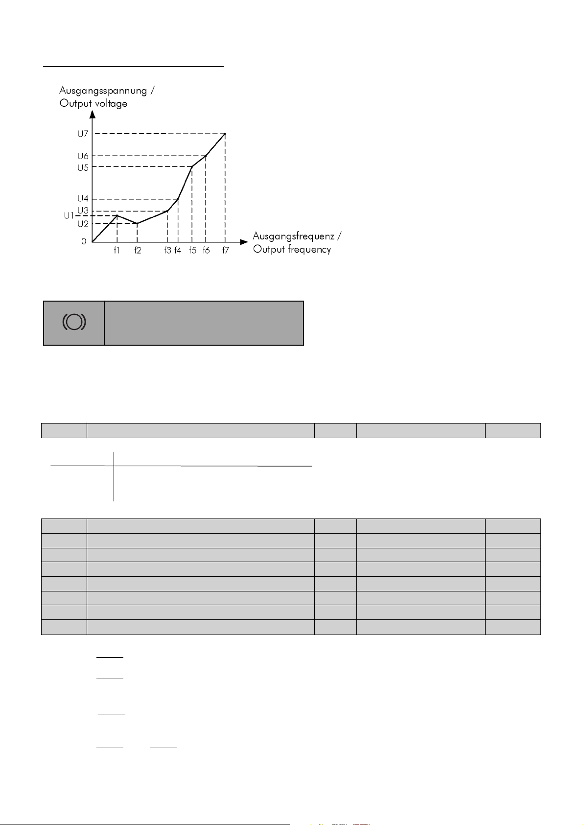
With parameters b100 to b113 a free adjustable V/f characteristic can be programmed.
The parameters for torque boost (A041 / A241) and for the base frequency (A003 / A203) are not
active.
Page 28
Operating & Mounting instructions – 8 074 143.03/03 – Page 26
F
ree adjustable V/f characteristic:
The frequency inverters >pDRIVE< CX profi have an adjustable DC brake. By locking a clocked DC
rotor voltage onto the base of the motor, the rotor produces a braking torque that
counteracts the rotation. With the help of the DC brake, braking a drive to minimum speed is
possible, before the mechanical brake is activated.
A051
Selection of DC braking VIC 00 or 01 00
Setting Function
00 can be controlled with digital input DB
01 alwaysactive
A052
DC braking: frequency VIC 0,00...60,00 Hz 0,50 Hz
A053
DC braking: waiting time VIC 0,0...5,0 s 0,0 s
A054
DC braking: braking torque VIC 0...70 % 0 %
A055
DC braking: braking time VIC 0,0...60,0 s 0,0 s
A056
DC braking: edge/level selection VIC 00 or 01 01
A057
DC braking: braking torque (start) VIC 0...70,0 % 0 %
A058
DC braking: braking time (start) VIC 0,0...60,0 s 0,0 s
A059
DC braking: carrier frequency VIC 0,5...12,0 kHz 3,0 kHz
Parameter A051
defines whether the internal DC brake is active or not.
Parameter A052
defines the frequency at which the DC brake starts. The setting is possible in the
range of 0,0 to 60,0 Hz.
Parameter A053
defines when the DC injetion braking is activated after the frequency set at A052 is
exceeded. During this time the motor is running idle.
Parameter A054
and A057 define the power value with which DC injection braking is carried out.
0% mean “very low“ and 70% “very high“.
DC brake
Braking
Page 29

Operating & Mounting instructions – 8 074 143.03/03 – Page 27
Parameters
Parameter A055 and A058 define the duration of DC injection braking. The value is set within the
range from 0,1 to 60 seconds.
Parameter A056
defines wheter the DC brake is active depending on time or depending on a
contact.
Parameter A059 defines the carrier frequency during DC braking. With high carrier frequency the
maximum possible braking torque is reduced.
DC brake always active (A051=01):
If the DC brake is active (A051 = 01) this function is active at each Start and/or Stop.
After the Start-command the DC brake is active during the time set with parameter A058.
After the Stop-command the inverter runs down along the set deceleration ramp and starts with DC
braking at the frequency set with parameter A052.
Page 30

Operating & Mounting instructions – 8 074 143.03/03 – Page 28
Note:
The DC brake causes a heating of the connected motor.
Be sure that the motor does not get to warm.
DC brake controlled via digital input (A051=00)
The DC brake is activated via a digital input (D8: C001...C005=7).
Page 31

Operating & Mounting instructions – 8 074 143.03/03 – Page 29
Parameters
b090
Dynamic braking ratio VIC 0,0...100,0 % 0,0 %
Adjusting the allowed duration time of the braking resistor (only at CX profi 11 and 15).
Setting 0,0 % means that the internal braking unit is not active.
Frequency limits
Limits
A061
Frequency upper limit VIC 0,00...400,0 Hz 0,00 Hz
A062
Frequency lower limit VIC 0,00...400,0 Hz 0,00 Hz
Defining the frequency range within a range from 0 to parameter A004 (max. 400 Hz). If the values
are set to 0,00 Hz, their function is cancelled.
Without parameter A061 and A062 With parameter A061 and A062
b095
Dynamic braking selection VIC 00 to 02 00
Setting Function
00 not active
01 only active during operation
02 always active
b096
Dynamic braking ON-level VIC 660...760 V 720 V
Defines the ON-level of the braking unit depending on the DC link voltage.
Page 32

Operating & Mounting instructions – 8 074 143.03/03 – Page 30
A063
1st Jump frequency VIC 0,00...400,0 Hz 0,00 Hz
A064
1st Jump frequency width VIC 0,00...10,0 Hz 0,50 Hz
A065
2nd Jump frequency VIC 0,00...400,0 Hz 0,00 Hz
A066
2nd Jump frequency width VIC 0,00...10,0 Hz 0,50 Hz
A067
3rd Jump frequency VIC 0,00...400,0 Hz 0,00 Hz
A068
3rd Jump frequency width VIC 0,00...10,0 Hz 0,50 Hz
To avoid possible resonance in the drive system, it is possible to program three jump frequency
ranges using functions A063...A068.
The jump frequency defines the frequency at which the drive should not be operated in steady-state.
The adjustable jump frequency range determines the frequency range faded out and actions
symmetrical to the jump frequency.
General
The PID controller is designed as a process controller with the variable “Frequency [Hz]”, whereby
P (kp), I (T
N) and D (Tv) can be adjusted individually. The reverence and actual value are standardi-
sed in % (range 0...100 %). For better presentation, they can be converted to the individual plant
value using A075 (e.g. flow 0...30 l/h).
The PID controller output is limited with 0 Hz (or A062) at the bottom and with the maximum
frequency A004 (or A061) at the top end. As a result, there is no reversal of the motor in the event
of negative deviation.
In order to optimize the disturbance behaviour of the controller, it is advisable to set the acceleration
and deceleration ramps as small as possible.
PID Configuration
PID
Page 33

Operating & Mounting instructions – 8 074 143.03/03 – Page 31
Parameters
PID reference value
The reference value is selected using parameter A001. The following values can be used as
reference source:
Reference value Settings Standardization
Potentiometer built-in A001 = 00 0...100 %
Parameter value F001 A001 = 02 0...100 % x Parameter A075
Multispeeds A020...A035 0...100 % x Parameter A075
Analog input O (0...10 V) A001 = 01 0...100 % (independent from A011...A014
Analog input OI (4...20 mA) 0...100 % or A101...A104)
Actual value
One of the two analog inputs (O or OI) can be used as actual value input (selectio with A076).
The actual value registration is adjusted using the analog input function.
See parameters A011...A014 or A101...A104.
The settings of parameters A011 and A012 are changed by activating the PID controller (A071)
from Hz to % and by setting parameter A075 to process values.
Note:
By using the PID controller, the digital function “Automatic reference value (4..20 mA)” is not available!
Note:
Because of the influence of parameter A071 to the scaling of the reference and actual value, it is
important to change this parameter before changing any other!
Displays
Parameter d004 allows the display of the actual value, parameter F001 displays the reference value
on the LED. This values can be converted to process values using the display factor A075.
If parameter F001 is selected, the current PID reference value is displayed. It is not updated continuously.
The actual value display (parameter d004) is updated continuously.
Page 34

Operating & Mounting instructions – 8 074 143.03/03 – Page 32
A071
Selection of PID function: ON/OFF VIC 00 or 01 00
The PID controller is activated and deactivated using parameter A071.
Setting Function
00 PID controller not active
01 PID controller active; with digital input to setting 23 (PID enable) switch-over to
manual control
Generally is:
T
N is right at kp = 1
kp ≠ 1 ⇒ T
N = TN x kp
TN = selected reset time (A073) at kp = 1
T
N* = effective reset time at kp = 0,5
T
N* = TN x 0,5
*) After setting the scale conversion (parameter A075) this parameters are adjusted and displayed in process
sizes.
**) If the PID controller is active, the reference value is set and displayed in percent or in process size
dependent on A075. By switch-over to manual controll (DIx ... 23 PID enable) the values are scaled and
also displayed in Hz.
This values are scaled with parameters A011...A014 (terminal O [V]) and A101...A104 (terminal OI [mA]).
The display parameters F001 and d004 are updated continuously !
A072
PID controller: Proportional gain (kp) VIC 0,2...5,0 1,0
A073
PID controller: Integral gain(Tn) VIC 0,0...3600 s 1,0
A074
PID controller: Differential gain(Tv) VIC 0,00...100,0 s 0,00
Parameters A072, A073 and A074 are used to
set the PID controller factors.
Please not that the individual factors can be set
separately, but that they have an influence on
each other. If P (kp) is changed, T
N also
changes
..
Page 35

Operating & Mounting instructions – 8 074 143.03/03 – Page 33
Parameters
A075
PID controller: Scale conversion VIC 0,01...99,99 1,00
Parameter A075 allows the setting of a conversion factor for the proper process presentation of the
PID reference and actual value on the LED display.
Parameters A011 (A101), A012 (A102), d004, F001 and A020...A035 are converted in accordance
with the setting of A075.
A076
PID controller: Feedback destination VIC 00 or 01 00
Parameter A076 defines the type of feedback signal.
Setting Function
00 Current signal at terminals OI - L
01 Voltage signal at terminals O - L
C044
PID controller: Level of deviation VIC 0...100 % 3,0 %
Adjusting the difference between reference and actual value in percent, at which a signal is to be
issued. The setting can be done in a range from 0,0 to 100,0 % with a resolution of 0,1 % (bipolar).
The AVR function (Automatic Voltage Regulation) stabilises the motor voltage in case of fluctuating
intermediate circuit voltage (e.g. due to unstable mains supply or because of intermediate circuit
voltage drops or surges due to short acceleration or deceleration times) in order to maintain such a
high torque - especially during acceleration.
Automatic voltage regulation
AVR
V/f
During the delay phase (generatoric operation) the DC link voltage increases (as shown above). This
leads to an increase of the motor voltage. This higher motor voltage causes a higher braking torque.
Therefore, the AVR function for deceleration can be deactivated with function A081.
Page 36

Operating & Mounting instructions – 8 074 143.03/03 – Page 34
A081
Selection of AVR function VIC 00 to 02 00
Parameter A081 switches the “Automatic Voltage Regulation” for the motor on and off.
Setting Function
00 AVR function active
01 AVR function not active
02 AVR function not active during deceleration
A082
Selection of voltage for AVR VIC 380...480 V 400 V
The nominal motor voltage (380 / 400 / 415 / 440 / 460 / 480 V) is set with parameter A082.
(output voltages higher than the mains voltage are not possible)
Allows to switch the time ramps adjusted with F002 and F003 to the ramps adjusted with A092 and
A093 during operation. This can be done either at any time using an external signal or when exact,
set frequencies are reached.
Ramp adjustment
Speed ramps
2.
A092
2nd Acceleration ramp VIC 0,01...3600 s 15,00 s
A093
2nd deceleration ramp VIC 0,01...3600 s 15,00 s
A094
Select method of 2nd stage VIC 00 or 01 00
Setting Function
00 Switch-over via an external signal on a digital input (setting: 09)
01 Switch-over when the frequencies set at parameter A095 and A096 are reached
Page 37

Operating & Mounting instructions – 8 074 143.03/03 – Page 35
Parameters
A095
Switch-over 1./2. acceleration ramp VIC 0,00...400,0 Hz 0,00 Hz
A096
Switch-over 1./2. deceleration ramp VIC 0,00...400,0 Hz 0,00 Hz
Particularly, this switch-over is used for EMERGENCY STOP functions and speed-related acceleration
and deceleration times. The adjusted acceleration/deceleration time is related to the maximum
frequency A004.
A097
Pattern of acceleration ramp VIC 00 to 03 00
A098
Pattern of deceleration ramp VIC 00 to 03 00
These two parameters determine whether the acceleration (A097) and/or deceleration (A098) are
linear or follow an S ramp.
Setting Function
00 linear
01 S ramp
02 U ramp
03 U ramp inverted
A131
Acceleration curve constant VIC 01 to 10 02
A132
Deceleration curve constant VIC 01 to 10 02
This two parameters determine how intensive the acceleration ramp (A131) and/or the deceleration
ramp (A132) have an S-curve. Setting: 01...slight S-ramp; 10...strong S-ramp
b091
Stopping mode selection VIC 00 or 01 00
This parameter defines the behaviour of the inverter after a Stop-command.
Setting Function
00 Deceleration ramp
01 Idle-run
A069
Acceleration stop frequency VIC 0,00...400,0 Hz 0,00 Hz
A070
Acceleration stop time VIC 0,0...60,0 s 0,0 s
With this function the acceleration process can be stopped. Parameter A070 defines how long the
acceleration process is stopped after reaching the frequency set with A069.
Page 38

Operating & Mounting instructions – 8 074 143.03/03 – Page 36
b012
Electronic overload setting VIC 0,2...1,2 x I
FI FI-INOM
A thermal motor contactor (“maximum continuous current”) can be set by entering the nominal
motor current in A.
b013
Electronic overload characteristic VIC 00 to 02 01
Defines the characteristic curve of the thermal motor contactor.
Setting Function
00 reduced load torque (self-ventilated)
01 constant load torque (force-ventilated)
02 free adjustable load torque
Thermal protection
Electronic Overload
Note:
If the value is higher than the nominal motor current, the motor cannot be protected by an
electronic motor contactor. In this case, thermistors or similar mechanism are required.
After a power cut, the thermal motor model always starts up again with a “cold” machine !!
b015
Free electronic thermal: frequency 1 VIC 0...400 Hz 0 Hz
b016
Free electronic thermal: current 1 VIC 0,0...1000 A 0,0 A
b017
Free electronic thermal: frequency 2 VIC 0...400 Hz 0 Hz
b018
Free electronic thermal: current 2 VIC 0,0...1000 A 0,0 A
b019
Free electronic thermal: frequency 3 VIC 0...400 Hz 0 Hz
b020
Free electronic thermal: current 3 VIC 0,0...1000 A 0,0 A
With this parameters the free adjustable electronic overload characteristic is defined (see above).
Page 39

Operating & Mounting instructions – 8 074 143.03/03 – Page 37
Parameters
b021
Selection of 1st overload restriction VIC 00 to 02 01
This parameter defines when the current limitation is active.
Setting Function
00 not active
01 during acceleration and constant speed
02 only at constant speed
b022
Level of 1st overload restriction VIC 0,5...1,5 x I
FI 1,20 x IN
Defines the value in amperes at which the inverter tries to reduce the load by decreasing the output
frequency.
b023
Rate of 1st decel. at overload restriction VIC 0,10...30,00 s 1,00 s
When reaching the adjusted current limit, the frequency is reduced according to the set ramp.
b024
Selection of 2nd overload restriction VIC 00 to 02 01
b025
Level of 2nd overload restriction VIC 0,5...1,5 x I
FI 1,20 x IN
b026
Rate of 2nd decel. at overload restriction VIC 0,10...30,00 s 1,00 s
With the parameters B021...b023 and b024...b026 two different overload restrictions can be set.
The switch-over is done via a digital input (OLR: C001...C005 = 39).
Overload protection
Overload restriction
A
Note:
The overload restriction is not active during deceleration.
Page 40

Operating & Mounting instructions – 8 074 143.03/03 – Page 38
C001
Function of input 1 VIC 01 to 39, NO 18
C002
Function of input 2 VIC 01 to 39, NO 16
C003
Function of input 3 VIC 01 to 39, NO 03
C004
Function of input 4 VIC 01 to 39, NO 02
C005
Function of input 5 VIC 01 to 39, NO 01
Parameter Control terminal Default
C001 1 18 External reset
C002 2 16 Switch-over O/OI
C003 3 03 CF2
C004 4 02 CF1
C005 5 01 Start reverse
The programmable inputs (control terminals 1 to 5)can be allocated to the parameters in
accordance with the following table:
Setting Short-cut Function Setting Short-cut Function
01 REV Start reverse 21 STP Stop impulse
02 CF1 Fix A 22 F/R Forward/reverse
03 CF2 Fix B 23 PID PID enable
04 CF3 Fix C 24 PIDC PID reset
05 CF4 Fix D 27 UP Motorpot increase
06 JG Jog mode 28 DOWN Motorpot decrease
07 DB DC braking 29 UDC Motorpot reset
08 SET 2nd set 31 OPE Local control
09 2CH 2nd accel./decel. ramp 32 SF1 FIX 1
11 FRS Impulse lock-free run 33 SF2 FIX 2
12 EXT External fault 34 SF3 FIX 3
13 USP Restart lock at 35 SF4 FIX 4
undervoltage (USP) 36 SF5 FIX 5
14 CS Bypass signal 37 SF6 FIX 6
15 SFT Software lock 38 SF7 FIX 7
16 AT Switch-over to automatic 39 OLR Switch-over of
ref. value 4...20 mA overload restriction
18 RS External reset NO NO no function
20 STA Start impulse
Digital inputs
Input terminals
Page 41

Operating & Mounting instructions – 8 074 143.03/03 – Page 39
Parameters
Explanations of the functions for the digital inputs
Start/Stop via switch contacts:
When the contacts are closed, a Start command is
issued in the right direction (acceleration on
gradient), when open, a stop command is issued
(deceleration on gradient). The simultaneous
closing of Start forward and Start reverse also
issues a Stop command to the inverter.
Multispeeds (“binary” function):
The multispeeds (maximum 15) are selected via
the signals CF1...4 according to the table:
CF1 CF2 CF3 CF4 Reference value
0 0 0 0 analog value
1 0 0 0 1 (A021)
0 1 0 0 2 (A022)
1 1 0 0 3 (A023)
0 0 1 0 4 (A024)
1 0 1 0 5 (A025)
0 1 1 0 6 (A026)
1 1 1 0 7 (A027)
0 0 0 1 8 (A028)
1 0 0 1 9 (A029)
0 1 0 1 10 (A030)
1 1 0 1 11 (A031)
0 0 1 1 12 (A032)
1 0 1 1 13 (A033)
0 1 1 1 14 (A034)
1 1 1 1 15 (A035)
The number of digital inputs to be programmed
depends on the number of multispeeds actually
needed. The multispeeds are programmed in
parameter group A. The multispeeds are pure
reference values without any Start/Stop
commands.
Therefore, Parameter A001 “Method of speed
command” must be set to 01 “control terminals” !
Jog mode:
If the Jog command is activated, the inverter
accelerates the motor with the fastest possible
acceleration time to the set jog frequency A038.
00 Start FWD
01 Start REV
02 Fix A
03 Fix B
04 Fix C
05 Fix D
06 Jog mode
Page 42

Operating & Mounting instructions – 8 074 143.03/03 – Page 40
DC brake:
If this command is activated, the DC brake is
active.
Switch-over of parameters:
If this command is activated, the inverter switches
over to the 2nd set of parameters. Motor data,
minimum and maximum limits and the acceleration and deceleration times are switched over.
The concerned parameters are named A2xx.
Switch-over of ramps:
Two sets of acceleration and deceleration ramps
are avaliable. The signal “2nd ramp” is used to
switch between these two ramp sets. The values of
acceleration and deceleration time must be set in
parameter group A.
Contact closed: 2nd set of ramps active
Impulse lock:
If this command is activated, the inverter is locked
immediately, allowing the motor to come to standstill freely. The function can be inverted
(parameters C011 to C015). By setting parameter
b088 to position 00, the inverter starts from 0 Hz
once the FRS signal is cancelled.
However, if parameter b88 is set to position 01,
the inverter starts with the acutal frequency fo the
motor (“interception of the motor“).
In both cases, the inverter starts after the waiting
time set with parameter b003. If the speed of the
motor is declined during this time beneath the
matching (restart) frequency set with parameter
b007, a restart happens at 0 Hz.
07 DC brake
08 2nd Set
09 2nd ramp
11 Impulse lock
Netzspannung/
Mains supply
FRS-Signal/
FRS command
Ausgangsfrequenz
Output frequency
b088=00
Ausgangsfrequenz
Output frequency
b088=01
1
0
1
0
1
0
1
0
Page 43

Operating & Mounting instructions – 8 074 143.03/03 – Page 41
Parameters
External fault:
The activated command leads to immediate fault
shut-down with the error message „E12 - Ext.
fault“. Using this input, plant errors can be
integrated in the control of the frequency inverter.
The error message cn be realised using the break
or make contact (parameter C011 to C015).
Restart lock for undervoltage (USP)
This function prevents an automatic motor start
when the voltage returns after a power cut or
undervoltage. A restart is only possible after
resetting the error or by switching the Start
command on/off.
12 Ext. fault
13 USP
Notes:
If the USP function is activated and the
power supply comes back or is
switched-on during a Start-command,
the inverter trips with E13.
The USP function is also executed after
an undervoltage trip E09.
Netzspannung/
Mains supply
Startbefehl/
Start command
USP-Klemme/
USP-terminal
USP-Meldung/
USP-message
1
0
1
0
1
0
1
0
Ausgangsfreq./
Output freq.
1
0
Page 44

Operating & Mounting instructions – 8 074 143.03/03 – Page 42
Bypass signal:
An activation of the command leads an holding of
the running motor after mains operaiton.
After the switch-over from bypass to inverter operation, the inverter takes over the running motor
after the waiting time set with parameter b003.
If the speed of the motor has declined during this
time the matching (restart) frequency set with
parameter b007, a restart is done at 0 Hz.
Software lock:
This function allows an additional lock for
parameter changes via the terminals. Thus, it is
possible e.g. to lock the parameter editing
function via an externa key switch.
Contact open: parametrization enabled,
Contact closed: parametrization locked.
Switch-over to automatic reference value
(4..20 mA)
By closing the contact, it is possible to define the
frequency ref. value usnig a current input signal
(4...20mA). When the contact is open, the
frequency is defined via a voltage input signal
(0...10V). If the contact is closed, the frequency is
defined via the 4...20 mA analog input (terminals
OI - L). If the contact is open, the analog signal
0...10 V (terminals O - L) is conductive. If no
digital input is parametrized for this function, the
two reference values are added (f-correction).
15 Software lock
14 Bypass signal
16 Automatic ref.
value (4 .. 20 mA)
Bypaßschütz/
bypass contactor
Motorschütz/
Motor contactor
Netzschütz/
Mains contactor
CS
Ausgangsfreq./
Output freq.
1
0
1
0
1
0
1
0
1
0
Verriegelungszeit/
Cut-off time
0,5...1s
b003
Page 45

Operating & Mounting instructions – 8 074 143.03/03 – Page 43
Parameters
External reset:
Allows you to confirm an error via the terminals.
During operation, an external Reset-command
stops the inverter!! The signal must not be inverted
and must not be issued for more than 4 seconds.
A permanent reset is not possible. If the inverter is
running without problems, it runs to 0 Hz when an
RS signal is issued! In plants, where a common
reset signal is used for all devices, parameter
C102 must be set to position 02 !
Start/Stop via impulses:
An impulse contact (N.O.) leads a Start-command.
An impulse contact (N.C.) leads a Stop-command.
Closing the contact leads to a change of direction.
Contact open = Forward
PID controller:
If the PID controller is activated (A071=1), the
command “PID enable” disables the PID
controller and the PID ref. value acts directly on
the output frequency.
Motorpotentiometer:
Reference values via the motorpotentiometer are
defined via the signals “Motorpot increase” and
“Motorpot decrease”.
Thereby, the reference value is increased and
decreased with the adjusted acceleration/
deceleration time (F002/F003 and F202/F203) as
long as the command is active.
The motorpotentiometer is activated via parameter
A001 = 02.
The command “Motorpot reset” deletes the
reference value, if he is stored with parameter
C101 = 01.
Local control:
By closing this contact, the control via the keypad
is activated. After pressing the RUN key, the
inverter accellerates up to the reference value set
with F001 - independent from A002 “Method of
run command”.
If the contact is closed during operation, the drive
stops first.
18 External reset
20 Start impulse
21 Stop impulse
22 Forward/
reverse
27 Motorpot increase
28 Motorpot decrease
29 Motorpot reset
23 PID enable
24 PID reset
31 Local control
Page 46

Operating & Mounting instructions – 8 074 143.03/03 – Page 44
Multispeeds (“bit”-function):
The multispeeds (maximum 7) are selected using
the signals SF1...SF7 according to the table:
SF1 SF2 SF3 SF4 SF5 SF6 SF7 Ref. value
0000000analog value
1xxxxxx 1 (A021)
01xxxxx 2 (A022)
001xxxx 3 (A023)
0001x x x 4 (A024)
00001x x 5 (A025)
000001x 6 (A026)
0000001 7 (A027)
If several multispeeds are selected at one time, the
lower value has priority.
The number of multispeeds depends on the actual
number of digital inputs. Maximum 5 free
adjustable digital inputs are available at a
standard control terminal.
The multispeeds are programmed in parameter
group A. The multispeeds are pure reference
values without any Start/Stop commands.
Switch-over of overload restriction:
With this command a switch-over between the two
different overload restrictions (b021...b023 and
b024...b026) is possible .
This command has no effect !
Notes:
You can not use the same value for parameters C001 to C005.
If a parameter is to be shifted to another terminal, the “from” terminal must be set first,
then the old value set for the “to” terminal.
32 Fix 1
33 Fix 2
34 Fix 3
35 Fix 4
36 Fix 5
37 Fix 6
38 Fix 7
39 Switch-over of
overload restriction
NO no function
Page 47

Operating & Mounting instructions – 8 074 143.03/03 – Page 45
Parameters
C011
Condition of input C001 VIC 00 or 01 00
C012
Condition of input C002 VIC 00 or 01 00
C013
Condition of input C003 VIC 00 or 01 00
C014
Condition of input C004 VIC 00 or 01 00
C015
Condition of input C005 VIC 00 or 01 00
C019
Condition of input FW VIC 00 or 01 00
This parameters define the status of the programmable digital inputs C001 to C005 and FW.
Setting State
00 N.O.
01 N.C.
b098
Thermistor type seleciton VIC 00 to 02 00
Setting Function
00 Thermistor not active
01 Thermistor active (PTC-behaviour)
02 NTC active
b099
Thermistor error level VIC 0...9999 Ω 3000 Ω
This parameter defines the trigger value of the thermistor monitoring.
C085
Standardization of thermistor input VC 0...100 Default
This balance is set in factory and should not be changed.
C101
Reference up/down selecteion VIC 00 or 01 00
Setting Function
00 Does not store value of motorpotentiometer
01 Stores value of motorpotentiometer
C102
Reset function selection VC 00 to 02 00
Setting Function
00 Reset at positive ramp
01 Reset at negative ramp
02 Reset at positive ramp, no effect during operation
If position 00 or 01 is adjusted, a Reset-signal during operation locks the output.
C103
Reset restart function selection VIC 00 or 01 00
Setting Function
00 Restart with 0 Hz
01 Holds the motor during restart
Page 48

Operating & Mounting instructions – 8 074 143.03/03 – Page 46
C021
Function of relay 11 VIC 00 to 13 01
C022
Function of relay 12 VIC 00 to 13 00
C026
Function of relay AL VIC 00 to 13 05
The programmable relay outputs (terminals 11 and 12 and also AL) can be programmed using
parameters C021, C022 and C026. The following functions can be programmed:
Setting Short-cut Function
00 RUN Operation
01 FA1 „Reference value arrival“ - signal
02 FA2 „Frequency exceeded“ - signal (C042, C043)
03 OL Overload message
04 OD PID deviation too high
05 AL Error message
06 FA3 „Frequency arrival“ - signal (C042, C043)
08 IP Mains failure
09 UV Undervoltage
11 RNT Operating hours motor exceeded (b034)
12 ONT Operating hours inverter exceeded (b034)
13 THM Temperature alarm (C061)
Function: RRUN C021, CC022 oor CC026 == 00 RRUN ““Operation”
Digital outputs
Output terminals
Note:
If the frequency value of the inverter is smaller than the start frequency (which is set with
parameter b082), there is no “Operation”-signal (RUN).
Function: FFA1 C021, CC022 oor CC026 == 001 FA1 “Ref. vvalue aarrival”
Function: FFA2 C021, CC022 oor CC026 == 002 FA2 “Frequency eexceeded”
Function: FFA3 C021, CC022 oor CC026 == 006 FA3 “Frequency aarrival”
The frequency at which the signal is to be issued during acceleration is set using parameter C042
(hysteresis -0,5 Hz bis +1,5 Hz).
The frequency at which th signal is to be issued during deceleration is set using parameter C043
(hysteresis +0,5 Hz bis -1,5 Hz).
Start-Befehl/
Start command
Ausgangsfrequenz/
Output frquency
Betrieb - Signal/
RUN - Signal
1
0
1
0
1
0
ON
Page 49

Operating & Mounting instructions – 8 074 143.03/03 – Page 47
Parameters
Function: OOL C021, CC022 oor CC026 == 003 OL “Overload mmessage”
This message is issued as soon as the motor current exceeds the value set for parameter C041, both
during motor and generator operation.
Funktion FA1: C021, C022 oder/or C026 = 1
Function: OOD C021, CC022 oor CC026 == 004 OD “PID ddeviation ttoo hhigh”
This message is issued as soon as the difference between reference value and actual value exceeds
the value set for parameter C044 (bipolar).
“Sollwert erreicht” / “Reference value arrival”
f
0.5 Hz
1.5 Hz
Funktion FA2: C021, C022 oder/or C026 = 2
“Frequenz überschritten” / “Frequency exceeded”
f
Ausgangssignal
60 ms
0.5 Hz
60 ms
f
C042
Ausgangssignal
1.5 Hz
Funktion FA3: C021, C022 oder/or C026 = 6
“Frequenz erreicht” / “Frequency arrival”
0.5 Hz
0.5 Hz
1.5 Hz
C042
Output
signal
60 ms
1.5 Hz
0.5 Hz
C043
1.5 Hz
C043
60 ms 60 ms
I [A]
b022
Motorstrom
Motor current
min. 1 sec
Überlastsignal /
overload signal
t
t
Page 50

Operating & Mounting instructions – 8 074 143.03/03 – Page 48
Function: AAL C021, CC022 oor CC026 == 005 AL “Error mmessage”
If one of the outputs C021 or C022 is set to position 05, an error signal is issued if an error occurs.
During mains failure the error signal will continue only as long as there is still power in the inverter.
Function: IIP C021, CC022 oor CC026 == 008 IP “Mains ffailure”
This message occurs as soon as the Input phase loss protection (b006) triggers.
Function: UUV C021, CC022 oor CC026 == 009 UV “Undervoltage”
This message occurs as soon as the undervoltage monitoring of the DC link triggers.
Function: RRNT C021, CC022 oor CC026 == 111 RNT “Operating hhours mmotor”
If the operating time of the motor (d016) exceeds the value set with b034, a message is indicated.
Function: OONT C021, CC022 oor CC026 == 112 OONT ““Operating hhours iinverter”
If the operating time of the inverter (d017) exceeds the value set with b034, a message is indicated.
Function: TTHM C021, CC022 oor CC026 == 113 THM “Temperature aalarm”
As soon as the thermal motor model exceeds the value set with C061, a message is displayed.
C031
Relay output 11: Inversion VIC 00 or 01 00
C032
Relay output 12: Inversion VIC 00 or 01 00
C036
Relay output AL: Inversion VIC 00 or 01 01
These parameters change the status of the programmable outputs.
Setting Function
00 normal (open)
01 inverted
Function Mains State Relay AL0-AL1 AL0-AL2 Function Mains State Relay AL0-AL1 AL0-AL2
„inverted“ ON Ready energized closed open „normal“ ON Ready de-energized open closed
(factory- ON Trip de-energized open closed ON Trip energized closed open
default) OFF ----- de-energized open closed OFF ----- energized open closed
Page 51

Operating & Mounting instructions – 8 074 143.03/03 – Page 49
Parameters
C040
Overload signal output mode VIC 00 or 01 00
Setting Function
00 Message during acceleration and constant frequency
01 Message only at constant frequency
C041
Level of overload signal 1 VIC 0...2 x I
NOM INOM
Setting the parameter within a range of 0 to 200 % with reference to the nominal current of the
inverter.
If the motor current exceeds the value of parameter C041, an overload signal is issued.
C042
Arrival signal for Acceleration 1 VIC 0,0...360,0 Hz 0,0 Hz
C043
Arrival signal for Deceleration 1 VIC 0,0...360,0 Hz 0,0 Hz
With C042 and C043 the frequencies are set, at which the output switches over.
Output functions
Output functions
C021, C022 oder/or C026 = 2
“Frequenz überschritten” / “Frequency exceeded”
f
f
C021, C022 oder/or C026 = 6
“Frequenz erreicht” / “Frequency arrival”
C042
Output
signal
0.5 Hz
60 ms
0.5 Hz
1.5 Hz
C043
C042
Ausgangssignal
0.5 Hz
60 ms 60 ms
1.5 Hz
1.5 Hz
C043
Page 52

Operating & Mounting instructions – 8 074 143.03/03 – Page 50
C061
Level of thermal motor protection VIC 0...100 % 80 %
This parameter defines the level, at which the alarm message “Temperature alarm” occurs at the
digital output. If this parameter is set to 0 %, the function is not active.
b034
Run/Power on time VC 0...9999 0
This parameter acts as reference for d016 and d017.
If the operating hours counter exceeds this value, an alarm message may occur, which can be
programmed to a digital output.
0. - 9999. Operating hours x 1
100 - 9999 Operating hours x 10
b001
Selection of restart mode VIC 00 to 03 00
Influences the behaviour of the frequency inverter in the event of an error.
Setting Function
00 Error message immediately
01 Autoreset with 0 Hz after the waiting time b003
02 Autoreset with “interception” of the motor after the waiting time b003
03 Autoreset with “interception” of the motor after the waiting time b003 with following
deceleration to 0 Hz and output of an error message signal
The inverter tries to reset 3x on I>> and U>>. At U<< the inverter tries to reset 16 times (b005).
Undervoltage / Autoreset
Re-Start method
Note:
Attention! Synchronisation to the motor speed is only possible if the speed is less than 40% of
the nominal speed and if the remanent motor voltage has not decreased too much (approx.
2...3 seconds).
b002
Allowable undervoltage time VIC 0,3...1,0 sec 1,0 sec
b003
Retry waiting time VIC 0,3...100,0 sec 1,0 sec
b002
Netzspannung /
mains supply
Umrichterstatus /
inverter condition
Motordrehzahl /
motor speed
1
0
Unterspannung
1
0
Under voltage
b003
Page 53

Operating & Mounting instructions – 8 074 143.03/03 – Page 51
Parameters
In the event of a low-voltage trip during operation, e.g. mains failure, the inverter switches to
impulse lock. If the voltage returns within the time set with b002, the inverter can be started again.
Otherwise, the unit shuts down with the message undervoltage.
If parameter b001 is set to 01, the time period b003 can be set after which the frequency inverter
tries to start-up again (after return of power). Of course, this will only happen if the power returns
within the set time.
b004
Undervoltage trip during stop VIC 00 to 02 00
Setting Function
00 Monitoring of undervoltage not active
01 Monitoring of undervoltage always active
02 Monitoring of undervoltage only during operation active
b005
Undervoltage Number of retry VIC 00 or 01 00
Setting Function
00 Tries to reset 16 times, then error message occurs
01 Tries to reset any times
b006
Input phase loss protection VIC 00 or 01 00
Setting Function
00 not active
01 active
b007
Matching frequency setting VIC 0,00...400,0 Hz 0,00Hz
This parameter defines the motor speed dependent behaviour at reset.
If the speed of the motor is higher than the frequency set with b007, the inverter tries to catch on the
fly and to accelerate to the set reference value.
If the speed of the motor is lower thant the frequency set with b007, a reset is done at 0,0 Hz.
General functions
Miscellaneous
F004
Running direction of RUN key - 00 or 01 00
Setting for direction of motor when controlling the motor via the RUN button on the control panel:
Setting Function
00 Forward
01 Reverse
Page 54

Note:
The acceleration and deceleration time is shorter, if the start frequency is increased.
Too high start frequency may cause a sweep (breakover) of the motor. Therefore, the starting
frequency should not be set higher than the slip frequency.
Operating & Mounting instructions – 8 074 143.03/03 – Page 52
b035
Direction restriciton (input) VIC 00 to 02 00
Setting Function
00 Forward and reverse possible
01 Only forward possible
02 Only reverse possible
b082
Start frequency adjustment VIC 0,10...9,99 Hz 0,50 Hz
The devices start with a minimum of 0,1 Hz.
The value can be increased to a maximum of 9,99 Hz in increments of 0,01 Hz.
b083
Carrier frequency setting VIC 0,5...12,0 kHz 3,0 kHz
Setting the switching frequency of the IPM module.
Note:
A lower switching frequency will reduce the disturbances and earth currents caused by the
cables, but will increase the motor noise on the other hand.
If the carrier frequency is higher than 3 kHz, the nominal current of the inverter must be
decreased.
b086
Frequency converted value setting VC 0,1...99,9 1,0
Conversion factor for the frequency display (see parameter d007).
d007 = frequency * b086
This factor is also used to adjust the “digital actual frequency” signal, which can optionally be issued
via the analog output FM up to a max. frequency of 3,6 Hz in proportion to the current frequency.
b087
Selection of STOP key VIC 00 or 01 00
Defines the function of the STOP button on the control panel.
Setting Function
00 STOP key always active
01 STOP key only in local operation active
b088
After FRS cancelled VIC 00 or 01 00
Defines the behaviour of the inverter after reseting the idle command (FRS).
Setting Function
00 Restart at 0 Hz
01 Restart at the acutal frequency (“interception”)
Page 55

Operating & Mounting instructions – 8 074 143.03/03 – Page 53
Parameters
H003
Motor kW rating VIC 0,20...75,0 kW Default
H004
Motor poles VIC 2 / 4 / 6 / 8 4
With this parameters the nominal motor data according to the type plate are adjusted.
H006
Motor stabilisation constant VC 0...255 100
With the help of this parameter the drive can be stabilized. If the motor does not run roundly, the
value must be increased. If the inverter operates a motor with higher power than the inverter, the
value must be reduced.
Motor data
Motor data
2nd Set
2nd Set-up
A203 2nd Base frequency VIC 30...400 Hz 50 Hz
Adjustment of the base frequency. The base frequency is the frequency at which the output voltage
reaches its maximum value. Normally, the base frequency is equal to the nominal motor frequency
(more information see parameter A003).
A204 2nd Maximum Frequency VIC 30...400 Hz 50 Hz
Adjustment of maximum frequency. Between base frequency and maximum frequency the output
voltage is constant (field suppression).
F202 2nd Acceleration ramp VC 0,01...3600 s 30 s
Setting of required acceleration time. The time is in reference with the range from 0 Hz to maximum
frequency (parameter A204).
b092
Cooling fan control VIC 00 or 01 00
Setting Function
00 Fan is alway running
01 Fan runs only during operation
(after mains switch-on and after stop-command the fan still runs 5 minutes)
b037
Display selection VIC 00 to 02 00
This parameter must be always set to 00.
Page 56

Operating & Mounting instructions – 8 074 143.03/03 – Page 54
F203 2nd Deceleration ramp VC 0,01...3600 s 30 s
Setting of required deceleration time. The time is in reference with the range from 0 Hz to maximum
frequency (parameter A204).
A220 2nd Internal pre-set speed VC 0,00...400,0 Hz 0,00 Hz
Entry of frequency reference value, if function A001 is set to position 02. Allows the entry of a
minimum frequency to which the inverter runs up without selecting a digital input “CF1...CF4” as
soon as a Start-command is issued.
If the PID controller is active, the adjusting range changes into 0 to 100 %.
A241 2nd Torque boost method selection VIC 00 or 01 00
Setting Function
00 manual boost
01 automatic boost
A242 2nd Manual torque boost setting VC 0,0...20,0 % 1,0 %
A243 2nd Manual torque boost frequency point VC 0,0...50,0 % 5,0 %
For applications which require higher starting torque, the standard starting torque can be increased
by up to 50 %. Use parameter A241 to select between automatic and manual boost. Parameter
A242 defines the value by which the torque has to be boosted. The range in which this boost takes
effect is defined by parameter A243.
(more information see parameters A042 and A043)
A244 2nd V/f characteristic setting VIC 00 to 02 00
Parameter to set one of the possible V/f characteristics.
Setting Function
00 constant torque
01 reduced torque (Economy mode)
02 free adjustable V/f characteristic (b100...b113)
A261
2nd Frequency upper limit VIC 0,00...400,0 Hz 0,00 Hz
A262
2nd Frequency lower limit VIC 0,00...400,0 Hz 0,00 Hz
Defining the frequency range within a range from 0 to parameter A204 (max. 400 Hz). If the values
are set to 0,00 Hz, their function is cancelled (more details see parameters A061 and A062).
Page 57

Operating & Mounting instructions – 8 074 143.03/03 – Page 55
Parameters
A292
2nd Second acceleration ramp VIC 0,01...3600 s 15,00 s
A293
2nd Second deceleration ramp VIC 0,01...3600 s 15,00 s
A294
2nd Method of second stage selection VIC 00 or 01 00
Setting Function
00 Switch-over via an external signal on a digital input (setting: 09)
01 Switch-over when the frequencies set at parameter A295 and A296 are reached
A295
2nd Stage Acceleration change over point VIC 0,00...400,0 Hz 0,00 Hz
A296
2nd Stage Deceleration change over point VIC 0,00...400,0 Hz 0,00 Hz
Particularly, this switch-over is used for EMERGENCY STOP functions and speed-related acceleration
and deceleration times. The adjusted acceleration/deceleration time is related to the maximum
frequency A004.
b212
2nd Electronic overload setting VIC 0,2...1,2 x I
FIIN FU-INOM
A thermal motor contactor (“maximum continuous current”) can be set by entering the nominal
motor current in A (more information see parameter b012).
b213
2nd Selection of electronic overload charact. VIC 00 to 02 01
Defines the characteristic curve of the thermal motor contactor (more information see b013).
Setting Function
00 reduced load torque (self-ventilated)
01 constant load torque (force-ventilated)
02 free adjustable load torque
H203
2nd Motor kW rate VIC 0,20...75,0 kW Default
H204
2nd Motor poles VIC 2 / 4 / 6 / 8 4
With this parameters the nominal motor data according to the type plate are adjusted.
H206
2nd Motor stabilisation constant VC 0...255 100
With the help of this parameter the drive can be stabilized. If the motor does not run roundly, the
value must be increased. If the inverter operates a motor with higher power than the inverter, the
value must be reduced.
Page 58

Operating & Mounting instructions – 8 074 143.03/03 – Page 56
Analog outputs
Analog output
C027
Function of FM PWM output VIC 00 to 07 00
C028
Function of AM analog output VIC 00 to 07 00
C029
Function of AMI analog output VIC 00 to 07 00
Programming the function of the analog/digital output FM and of the analog outputs AM and AMI.
Setting Function
00 Analog display of the frequency
01 Analog display of the current
03 Digital display of the frequency (setting only possible at C027)
04 Analog display of the output voltage
05 Analog display of the power taken up
06 Analog display of the thermal utilization
07 Analog display of the LAD frequency
Function: Display ooutput ffrequency C027, CC028 oor CC029 == 000
10V or 20mA correspond with the maximum frequency (parameter A004 or A204).
Function: Display oof mmotor ccurrent C027, CC028 oor CC029 == 001
10V or 20mA correspond with 200% of the nominal inverter current.
Function: Digital ooutput ffrequency CC027 == 003
There is a digital frequency signal corresponding to the output frequency at the output. The output
delivers a 1:1 square signal with 10 V amplitude (a different multiplication factor, max. 3,6 kHz, can
be set using parameter b086).
This function is only possible at analog/digital output FM (parameter C027).
Function: Analog ddisplay oof mmotor vvoltage C027, CC028 oor CC029 == 004
10V or 20mA correspond with the maximum motor voltage A082.
Function: Analog ddisplay oof ppower cconsumption C027, CC028 oor CC029 == 005
10V or 20mA correspond with 200% of the nominal inverter power.
Page 59

Operating & Mounting instructions – 8 074 143.03/03 – Page 57
Parameters
Energy saving
Energy Saving
e
A085
Operation mode selection VIC 00 or 01 00
Setting Function
00 Operation mode not active
01 Operation mode active
A086
Energy saving response VC 0,0...100,0 50,0
Parameter A086 defines the voltage decrease at energy saving. If A086 = 0,0 the voltage is not
reduced but at 100,0 the voltage is very much reduced.
Function: Analog ddisplay oof tthermal uutilization C027, CC028 oor CC029 == 006
10V or 20mA correspond with the maximum thermal utilization of the motor (in accordance with the
thermal motor model: parameter b012 or b212 “Electronic overload setting”).
Function: Analog ddisplay oof LLAD-ffrequency C027, CC028 oor CC029 == 007
10V or 20mA correspond with the maximum frequency (parameter A004 or A204).
b080
AM analog adjustment VC 0...255 180
b081
FM PWM meter adjustment VC 0...255 60
With this parameter the analog output AM and the digital PWM-output FM can be adjusted. At the
FM output the changed relation of pulse and pause can lead to full-scale deflection at maximum
output value.
C086
AM analog offset VC 0,0...10,0 V Default
C087
AMI analog adjustment VC 0...255 50
C088
AMI analog offset VC 0,0...20,0 mA Default
This adjustments are done in factory and should not be changed!
Page 60

Operating & Mounting instructions – 8 074 143.03/03 – Page 58
Option cards
Option card
PCB
2
1
P001
Option 1 Selection on error VIC 00 or 01 00
P002
Option 2 Selection on error VIC 00 or 01 00
This parameter defines, if an error in the connection with the option cards leads a trip message or
not.
Setting Function
00 Error
01 No error
C070
Data command VIC 02 to 05 02
C071
Transmission speed VIC 02 to 06 04
C072
Identification code VIC 1...32 1
C073
Data bits VIC 7 or 8 7
C074
Parity VIC 00 to 02 00
C075
Number of Stop bits VIC 1 or 2 1
C078
Waiting time VIC 0...1000 ms 0
Parameters C070...C078 allow the configuration of the serial interface RS485.
Serial communication
Communications
RS485
This function is not supplied at the moment !
Page 61

Operating & Mounting instructions – 8 074 143.03/03 – Page 59
Parameters
Software lock, Factory default
b031 Software lock VIC 00 to 10 01
Locks or releases adjustment of parameters.
Setting Function
00 All parameters locked (excepted parameter b031) as long as there is a lock signal
at the control terminals (set one of the parameters C001...C005 to position 15)
01 All parameters locked (excepted parameter b031 and frequency reference value
F001) as long as there is a lock signal at the control terminals (set one of the
parameters C001...C005 to position 15)
02 All parameters locked (excepted parameter b031) as long as parameter b031 is set
to position 02
03 All parameters locked (excepted parameter b031 and frequency reference value
F001) as long as parameter b031 is set to position 03
10 All parameters locked (excepted parameter b031) and all parameters, which can be
adjusted during operation, are active as long as parameter b031 is set to 10.
b084 Factory default setting VIC 00 to 02 00
Setting Function
00 Delete error message
01 Reset to factory default (see “Commissioning”)
02 Deletes error message and resets to factory default
b085 Kind of factory default VIC 00 to 03 01
Selection of factory defalt.
Setting Function
00 01 Factory default of parameters for Europe
02 Factory default of parameters for USA
03 -
Page 62

Operating & Mounting instructions – 8 074 143.03/03 – Page 60
Notes
Page 63

If no trip has occured, the display indicates:
Operating & Mounting instructions – 8 074 143.03/03 – Page 61
Displays
d080 Number of trips - read only -
Display of the number of trip messages on the LED display.
d081...d086 Trip messages - read only -
Parameters d081 to d086 display the last error messages. They show the output frequency, the
motor current, operating hours of motor and inverter during fault at the display.
d081 shows the last error, d082 the error before ...
Fault memory
Page 64

Error messages
The frequency inverters have protection functions against e.g. overcurrent, overvoltage,
undervoltage,... In case of a trip, the output voltage is switched off, the motor stops idle and the
inverter stays in trip state until the trip is resetted.
No. Trip Possible ccause Remedy aactions
E01 Overcurrent or overvoltage of Sudden load spikes, Avoid sudden overloads,
the IPMs in static operation stalling motor, select inverter and motor with
short circuit on the motor terminals, higher power capacity,
earth fault, check motor cable and motor for
nominal motor current is higher than short circuit or earth fault,
nominal current of inverter decrease parameter A045
E02 Overcurrent or overtemperature Set deceleration time is too short, Increase deceleration time,
during deceleration short circuit at motor terminals, check motor cable and motor for
earth fault, short circuit or earth fault,
nominal motor current is higher than decrease parameter A045
nominal current of inverter
E03 Overcurrent or overtemperature Set acceleration time too short, Increase acceleration time,
of the IPMs during acceleration short circuit at motor terminals, check motor cable and motor for
earth fault, short circuit or earth fault,
set voltage boost to high, check the load and starting
stalling motor, torque,
nominal motor current is higher than decrease parameter A042
nominal current of inverter (A242)
E04 Overcurrent or overtemperature Too high ambient temperature Check ambient temperature;
during stand-still decrease parameter A045
E05 Triggering of the int. motor protection Motor overload Select an inverter and motor
with higher power capacity
E06 Overload of braking resistor Duration time of internal braking Increase deceleration time,
unit is too high increase duration time of
braking unit (b090)
E07 DC link overvoltage Set deceleration time is to short, Increase deceleration time,
motor is in generator-mode use a braking resistor,
do not activate AVR during
deceleration, adjust higher
motor voltage (A082)
E08 EEPROM error Above-average high data storage, The life time of the EEPROM
power supply failure during data is about 10000 storages
storage, (related to 10 years with a few
high electromagnetic fields, storages a day)
or too high ambient temperature
E09 Mains undervoltage Wrong mains voltage, Check input voltage
short mains losses
Operating & Mounting instructions – 8 074 143.03/03 – Page 62
Page 65

Operating & Mounting instructions – 8 074 143.03/03 – Page 63
Displays
No. Trip Possible ccause Remedy aactions
E10 Trips at the current transformers Current transformer is defect Replace current transfomer
E11 Trip of calculator Electromagnetic fields, Check of possible external
frequency inverter defect disturbances,
contact the customer service
E12 External fault An external fault is send via a Check the reason of the trip
digital input of the inverter and solve the problem
E13 Trip by restart lock Switch-on of mains voltage at The corresponding terminal must
active lock or mains failure at not be interconnected before
active lock switching on mains,
check mains voltage supply
E14 Earth fault on the motor terminals Earth fault Remove earth fault and check
the motor
E15 Mains overvoltage Mains overvoltage is higher than the Check the mains voltage
nominal voltage of the inverter
E16 Short mains failures Are there mains voltage dips in the Check the input voltage
range > 15ms ?
E21 Overtemperature in power part Inverter overload, Check the motor current,
ambient temperature too high check ambient temperature,
check fans
E23 Communication error Trip between CPU and interface Replace control printed circuit
E24 Phase failure A phase of the mains voltage fails Check mains voltage
or the mains voltage is switched off
during deceleration
E30 IGBT failure Is the motor bigger than the Select a frequency inverter of
frequency inverter ? higher performance.
Was there a sudden load increase Avoid overloads.
or is the motor stalling ? Use inverter and motor of
higher performance.
Is there a short-circuit of the motor Check motor and motor cables
terminals U, V, W ? for short-circuit.
E35 Motor thermistor activated Motor overload, Check load of the motor,
Is the self-ventilation of the motor - check built-in distances
especially at low speed - to less,
built-in distances to short
Page 66

Operating & Mounting instructions – 8 074 143.03/03 – Page 64
Error messages can be removed with Reset. There are several possibilities:
• Link the programmed input for short time with P24
• Press the STOP/RESET key on the keypad
• Switch-off the power supply
Note:
An inverter which operates without any failure, will decelerate to 0 Hz if an reset signal is
released !! Set parameter C102 “Reset function selection” to position 02 !!
If the error message stays after reset was released, please call your customer service
department or the supplier of the unit.
Page 67

Operating & Mounting instructions – 8 074 143.03/03 – Page 65
Displays
Alarm messages
The frequency inverter displays alarm messages (= H) if the parameter settings do not match.
Display Meaning
H001 / H201 A061 / A261 > A004 / A204
H
002 / H202 A062 / A262 > A004 / A204
H
004 / H204 A003 / A203 > A004 / A204
H
005 / H205 F001, A020 / A220 > A004 / A204
H
006 / H206 A021 - A035 > A004 / A204
H
012 / H212 A062 / A262 > A061 / A261
H
015 / H215 F001, A020 / A220 > A061 / A261
H
016 / H216 A021 - A035 > A061 / A261
H
021 / H221 A061 / A261 < A062 / A262
H
025 / H225 F001, A020 / A220 < A062 / A262
H
031 / H231 A061 / A261 < b082
H
032 / H232 A062 / A262 < b082
H
035 / H235 F001, A020 / A220 < b082
H
036 A021 - A035 < b082
H
037 A038 < b082
H
085 / H285 F001, A020 / A220 = A063 - A068
H
086 A021 - A035 = A063 - A068
H
091 / H291 A061 / A261 > b112
H
092 / H292 A062 / A262 > b112
H
095 / H295 F001, A020 / A220 > b112
H
096 A021 - A035 > b112
H
110 b100, b102, b104, b106, b108, b110 > b112
b100, b102, b104, b106, b108 > b110
b100, b102, b104, b106 > b108
b100, b102, b104 > b106
b100, b102 > b104
b100 > b102
H
120 b015, b017 > b019
b015 > b017
d090 Warning monitor - read only -
Parameter d090 also displays the actual warnings.
Page 68

Operating & Mounting instructions – 8 074 143.03/03 – Page 66
Further displays
Is displayed during initialisation, when switching on and if a reset
signal is issued.
Is displayed in the event of low voltage or mains failure.
The waiting time for automatic restart expires.
(see parameter b001 to b003)
Is displayed during initialisation of parameters and indicates the
initialisation version:
EU ... European version
USA ... American version
Is displayed during deleting the error list.
Is displayed during copying.
No data available (e.g. display under d081...d086 if the fault
memory is empty or display under d004 if the PID controller is not
active).
The keypad is not plugged-in correctly or there is no contact.
Page 69

Operating & Mounting instructions – 8 074 143.03/03 – Page 67
Projecting
Special safety instructions
Short mains failure
During a mains failure, the >pDRIVE< CX profi frequency inverter continues operating until the
intermediate circuit voltage drops below the minimum working level (approx. 20 % below the lowest
supply voltage). The time depends on the mains voltage before switching off, and on the load.
If a Start command is issued, the motor runs up again as soon as the power supply returns. This can
be blocked with the function "USP". If a digital input is parametrised for the function 13 USP "Restart
lock" and this signal is also issued, an error message (E13) is issued whenever the mains supply is
switched on, if a Start command has already been issued. (See description of parameters C001 to
C005)
Automatic restart
y After low mains voltage:
If a Start command is issued, there is an automatic restart every time the mains supply returns.
y After confirming an error
y After autoreset (parameter b001)
Frequencies > 60 Hz
When operating motors with frequencies over 60 Hz, the suitability of the corresponding components
must be checked first. An inquiry with the motor or machine manufacturer is important. 4-8 pole
motors are usually suitable for operation up to 100 Hz.
Insulation tests
All >pDRIVE< CX frequency inverters are tested for voltage stability and insulating resistance in
accordance with EN 50178. Insulating resistance measurements, e.g. within the scope of an
inspection, must be carried out between the short-circuited power terminals and earth only. For a
correct, complete insulation test, the CE filters must be disconnected.
Do not carry out any insulation resistance tests with the control terminals !!
Installation rules for compliance with CE regulations
The >pDRIVE< CX profi frequency inverters together with the available filter options CE-DR comply
with the EMV directive 89/336/EEC and the low-voltage directive 73/23/EEC, i.e. conformity with
EN 61800-3 and EN 50178
• Use of the option "CE-DR Filter" or use of an equivalent filter solution
• Assembly on a properly grounded metal assembly plate with good HF connection between the
motor cable screen and filter.
• Use and proper connection (bipolar !!) of screened motor cables
• Use of an AMF (Output Motor Filter) for greater motor cable lengths
• Use and proper connection of screened control cables
• Grounding the frequency inverter with at least 10 mm
2
personal safety
• Separate installation of motor cables and other cables, especially control wires
Page 70

Operating & Mounting instructions – 8 074 143.03/03 – Page 68
Technical Data
>pDRIVE< CX profi 11 15 18 22 30 37
Power data
Motor rating (recomended) 11 kW 15 kW 18,5 kW 22 kW 30 kW 37 kW
Continuous output power 15,2 kVA 20,1 kVA 25,3 kVA 29,4 kVA 39,4 kVA 48,4 kVA
Continuous output current 22 A 29 A 37 A 43 A 57 A 70 A
Nom. input current
without line choke 24 A 32 A 40 A 47 A 63 A 76 A
with line choke 21 A 28 A 36 A 42 A 56 A 68 A
Maximum current 120 % I
N
(>60 s / 10 min); 150 % INfor 0,5 s
Starting torque > 150% T
N
General data
Input voltage 3 AC 380...480 V ±10%; 50/60 Hz ±5%
Output voltage 3 AC, 0...100 % of mains voltage
Output frequency 0,1...400 Hz, adjustable
Base frequency 30...400 Hz, adjustable
Losses at 100% IN600 W 800 W 975 W 1150 W 1550 W 1900 W
at 70% I
N
435 W 575 W 700 W 820 W 1100 W 1350 W
Weight approx. 5 kg 12 kg 20 kg
Dimensions Height 260 mm 390 mm 540 mm
Width 210 mm 250 mm 310 mm
Depth 170 mm 190 mm 195 mm
Design / Protection degree Built-in unit for vertical mounting / IP20
Operating/Storage temp. -10...+40°C / -20...+65°C
Temperature increase +50°C with max. 2 kHz carrier frequency
Pollution degree 2 according to EN 50178
Cooling forced
Humidity 20...90%, non-condensing
Altitude ≤1000 m (above: power reduction of 1% per 100 m; max. 2000 m)
Braking function
Braking torque 80% with 60% with 10% without option 10% without
BR60R BR60R option
Internal braking unit built-in −−
External braking option BS 400/27 with BS 400/27 with BR20R BS 400/27
2 x BR60R parallel with BR20R
DC braking f, t and I adjustable
Page 71

Operating & Mounting instructions – 8 074 143.03/03 – Page 69
Projecting
General technical data
Standards CE-EMC directive in connection with optinal RFI filter and under
consideration of the installation remarks
CE low voltage directive, UL
Product standard EN 61 800-3 “Power drive system”
NSR directive 73/23 EWG
Vibration/ Shock 5,9 m/s² (0,6 G) 10...55 Hz (CX profi 37: 2,94 m/s² (0,3 G))
Protection class class 1 in accordance with EN 50178
Environmental class 3K3 in accordance with DIN IEC 721-3-3
Overvoltage class III in accordance with EN 50178
Frequency resolution digital: 0,1 Hz, analog: f
MAX
/1000
Frequency stability digital ±0,01 % of f
MAX
; analog ±0, 2 % of f
MAX
Reference voltage +10 V, max. 20mA
Auxiliary voltage +24 V, max. 100 mA
Control method V/f - characteristic, PWM sine modulated
V/f-characteristic U/f-characteristics for constant and squared increasing torque;
output voltage, base and maximum frequency
base frequency adjustable
Carrier frequency 3 kHz, 0,5...12 kHz adjustable
Control Keypad or terminals
Analog input O 0...+10 V, Ri = 10 kΩ
Analog input O2 -10...+10 V, Ri = 10 kΩ
Analog input OI 4...20 mA, Ri = 100 Ω
Digital input FW +24 V, positive/negative logic
Digital input 1...5 +24 V, positive/negative logic
Thermistor input Ri = 10 kΩ
PWM output FM 0...10 V; max. 1 mA
Analog output AM 0...10 V; max. 2 mA
Analog output AMI 4...20 mA
Relay output AL max. 250 V AC
Relay output 11 max. 250 V AC
Relay output 12 max. 250 V AC
Protection functions for overcurrent, over- and undervoltage, earth fault, trip of fan,
overload, electronic motor protection
Options RFI footprint filter with line choke, output motor filter AMF
isolating amplifier TV5 / TV6
Busoption GW-PBO2 Gateway for Profibus DP
Page 72

Operating & Mounting instructions – 8 074 143.03/03 – Page 70
Remarks on power supply
Mains impedance
Virtually all frequency inverters produce harmonic oscillation when connected to the mains, which
can interfere with other devices due to the voltage distortions thus caused.
Please note that all converters with connected intermediate circuit voltage (diode rectifier at input)
are a load on the mains supply in their total output. The use of a line choke (integrated in the CEDR filter) is therefore highly recommended, even when using an industrial supply network.
It is absolutely necessary if: • the mains symmetry can be >3%
• the output of the upstream transformer is ≥ 500 kVA
• there are strong mains voltage drops
• the inverter is operated on a generator
• the inverter is used in residential areas
• several inverters connected via a short bus bar
are supplied by the mains network
Without a line choke, the above operating conditions can cause damage to the inverter!!
Safety remarks / FI safety switch
Frequency inverters, particularly those with CE filters (RFI filters) and screened motor cables, conduct
an increased leakage current to earth. This depends on:
• the length of the motor cable
• the type of installation and whether the motor cable is screened or not
• the set clock frequency
• the use of a radio interference suppression filters (yes or no)
• the grounding of the motor on location (grounded or not)
Especially at the moment of switching on the filter's capacitors and during operation, the earth capacities can lead to an unwanted FI safety switch trip. On the other hand, it is possible to block this trip
function through mains rectification at the input of the inverter with d.c. components.
Therefore, please note the following:
• Use only short-time delayed and clock-sensitive FI safety switches with considerably higher rated
trip current.
• Protect other consumers with a separate FI safety switch.
• FI safety switches upstream from a inverter are not an absolute safeguard against direct
contact!! Therefore, they should always be used in conjunction with other protective measures.
• The >pDRIVE< CX frequency inverters do not have a current-limiting effect (with fault currents),
and thus do not violate the grounding conditions.
In plants with cables of medium length, the leakage current can easily be greater than 300 mA,
depending on the conditions!!
Page 73

Operating & Mounting instructions – 8 074 143.03/03 – Page 71
Projecting
Mains fuses and cable diameters
1.) 2.) 1.) 4.) 5.) 1.) 1.) 3.)
Mains ssupply Frequency iinverter Motor-
output
Pre-oor Mains ffuse Lines iin tthe Max. CConnec-MMotor
conduit Cu ccable “inverter cubicle >pDRIVE< contin. tion cable
fuses protection” ““sf” (per pphase) current
40 A 3x6 mm
2
32 A 6 mm
2
CX profi 11 22 A M6 3x6 mm
2
50 A 3x10 mm
2
40 A 10 mm
2
CX profi 15 29 A M6 3x6 mm
2
63 A 3x16 mm
2
50 A 10 mm
2
CX profi 18 37 A M6 3x10 mm
2
63 A 3x16 mm
2
50 A 10 mm
2
CX profi 22 43 A M6 3x10 mm
2
80 A 3x25 mm
2
63 A 10 mm
2
CX profi 30 57 A M6 3x10 mm
2
100 A 3x35 mm
2
80 A 16 mm
2
CX profi 37 70 A M6 3x16 mm
2
K
ey to table:
1. The cable diameter indicated in the table are an index for laying the cable in air at max. 40°C,
based on the ÖVN EN 1 and VDE 0100 regulations.
For other ambient conditions and different regulations, the cable diameters must be
adjusted accordingly.
2. Pre-fuses calculated for DOL starting with bypass circuit.
3. The motor cables are designed for the maximum continuous current at an ambient temperature
of 40°C and laid in air. When a bypass circuit is used, the motor cable must be designed for the
value of the pre- or condiut fuses!
The use of NYCY or NYCWY cables for the motor cables (power cables with concentric protection
core) is a low-price alternative to screended cables.
4. In case of a trip, sf fuses protect the inverter from secondary damage in the rectifier, the charging
circuit etc.
The mains fuses represent a secondary protection of the inverter in the case of failure of the
electronic protection. However, if this fuses are blown, a primary defect has already occurred
inside the unit. Therefore, changing
the blown fuses and switching the inverter on again is not
effective. Furthermore, it is not advantageous to use circuit breakers. This has the disadvantage of
a slower switch-off.
5. If the inverter is used without
line choke (CE-DR filter) the fuses must be selected one type higher
to protect the inverter.
Page 74

Operating & Mounting instructions – 8 074 143.03/03 – Page 72
Remarks to the inverter output side
Motor cable lengths
The distances between inverter and motor indicated in the table in the chapter "CE-DR Options" must
be complied with. Too long motor cables can damage the inverters!
Option: AMF (output motor filter)
To reduce the voltage rate of rise on the inverter output and the effects on parallel lines thus possible, it is of advantage to use the AMF.
With long motor cables, the AMF protects the inverter and motor, and is absolutely imperative. See
table "Allocation Inverter Options Motor Cable Motor".
Especially with multimotor drives and the respective parallel motor cables, non-compliance with the
cable lengths can lead to destruction of the inverter.
Compensation capacitors
Compensation capacitors, mains filters and overvoltage protection equipment must never be
connected to the output of the inverters !!!
Switching at the inverter’s output
Operational switching between the inverter and the motor is not permissible. This would cause stress
load on the power semiconductor, and possible safety shut-down of the inverter !! This would shorten
the inverter's life !!!
Exception: A revision switch that is only used in very rare cases. Here, too, the CX should be
locked first, if possible (digital input programmed to 11 FRS "Impulse lock - idle").
Change of direction
Reversal protection switches for change in direction must not be used (see "Switching at the inverter's
output"). In order to change the direction of rotation, a digital input on the control terminal strip or a
parameter for direction selection (parameter F004) is provided.
Note:
Too long motor cables may damage the inverter.
Page 75

Operating & Mounting instructions – 8 074 143.03/03 – Page 73
Mounting
General Mounting Information
Make sure, that the input voltage is 3 AC 380...480 V ±10 %, 50/60 Hz ±5 %. Ambient factors
such as high temperatures, high humidity, dust, dirt and aggressive gases must be avoided. The
inverter should be installed in a well ventilated place that is protected against direct sunlight. Install
the inverter on a fire-proof, vertical wall that does not transmit vibrations.
Warning! Do not apply mains power to the output terminals U, V, W.
Issue the operating signals START/STOP via the control terminals or the control panel, not by
switching the mains or the motor contactor. Do not install capacitors or surge absorbers in the motor
wires.
Distances from other devices or against the wall
Because of thermal convection, the frequency inverters >pDRIVE< CX are designed for vertical wall
assembly. Especially when installing the inverter in a niche, you must comply with the specified minimum distance from side wall or other equipment. Objects that penetrate the interior of the inverter
can cause damage.
The permissible temperature range ( -10°C to +40°C, +50°C with 2 kHz clock frequency) must not
be undercut or exceeded. The higher the ambient temperature, the shorter the lifetime of the inverter.
Do not install the inverter near heat-radiating equipment.
When installing the inverter in a cubicle, please note the size and heat elimination capacity of the
cubicle. Provide ventilation, if necessary.
min.
100 mm
min.
50 mm
min.
50 mm
CX
CX
min.
100 mm
Luftstrom / airflow
Page 76

Operating & Mounting instructions – 8 074 143.03/03 – Page 74
Dimensions
>pDRIVE< CX profi 11 and 15
with option CE-DR 400/28
without filter RFI-filter incl. line choke
>pDRIVE< CX profi 18 to 30
with option CE-DR 400/56
without filter RFI-filter incl. line choke
>50
210
189
>pDRIVE<
CX profi
7
170
246
260
>50
7
>pDRIVE<
210
170
CX profi
255
286
306
>50
250
229
>pDRIVE<
CX profi
7
190
376
390
>50
7
>pDRIVE<
CX profi
250
210
300
416
436
Page 77

Operating & Mounting instructions – 8 074 143.03/03 – Page 75
Mounting
>pDRIVE< CX profi 37
with option CE-DR 400/68
without filter RFI-filter incl. line choke
>50
310
265
>pDRIVE<
CX profi
10
195
510
540
>50
9
>pDRIVE<
CX profi
310
265
295
560
580
Page 78

Operating & Mounting instructions – 8 074 143.03/03 – Page 76
Notes
Page 79

Operating & Mounting instructions – 8 074 143.03/03 – Page 77
Connection
Power connections
For wiring the power and control terminals, the front cover must be removed. Do not apply mains
power to the motor terminals U, V, W, since this can cause damage to the frequency inverter.
In multimotor operation, a motor protection relay must be provided for each motor.
Power connections
>pDRIVE< CX profi 11 and 15 >pDRIVE< CX profi 18 to 37
1.) If an external voltage supply is used to maintain the supply for the electronics, the internal
connection between terminals R0, T0 and plug J51 must be removed
Terminal Function Description
L1, L2, L3 Mains connection 3 AC 380...480 V ±10%, 50/60Hz ±5 %
U, V, W Motor connection 0...mains voltage (typ.: 3 AC 400 V)
+, − Braking unit (Option) Connection for the braking unit
+, RB Braking resistor (Option) Connection for the braking resistor at internal braking
unit (only at CX profi 11 and 15)
+1, + Connection for DC choke Linked (factory default) !!
PE connection Min. 10 mm
2
or 2 wires electronically parallel via two
separated terminals.
R
0
, T
0
Supply of mains part Connection for the voltage supply of the mains part.
Can be used to maintain the control voltage at
switched-off power part (1 AC 400V).
J51
J51
1.)
1.)
L1
L2L2L3
+
1+
UUVVW
RB
M
3~
R
0
T
R
0
0
+
L1
1+
L3
M
3~
T
0
W
Page 80

Operating & Mounting instructions – 8 074 143.03/03 – Page 78
2.) Control, mains supply and motor discharge should be separated, if possible
3.) Never install control lines, mains wires or motor cable in a common cable conduit!!
If control lines have
to cross power
cables, they should
do so at right
angles.
4.) Use only screened control lines (exception: relay contacts and digital inputs, if installed
completely separate from the power cables). The screen must always be grounded bilaterally
(exception: in case of earth circuit problems due to transient currents that heat the screen, only
the signal input side is grounded or a parallel compensating wire is installed).
Control lines
should be
separated from
motor cables by
a distance of at
least 30 cm.
5.) The primary function of the motor cable screen is to improve the connection between motor and
inverter, so that as little interfering current as possible flows past the filter to the mains earth.
Therefore, a screened 4-pole motor cable must be used and the screen must be connected
at both ends in accordance with the valid HF rules. The screening material (copper or steel) is less
important than good at both ends connection.
General connecting information:
1.) Power wiring with individual wires should always be
installed close to the corresponding PE conductor.
Page 81

Operating & Mounting instructions – 8 074 143.03/03 – Page 79
Connection
Control terminals
Externe Verdrahtung / external wiring
Interne Verdrahtung der Steuerklemmen /
internal wiring of the control terminals
+24V
NPN or PNP
Open-Collector
0V
4...20mA
1 bis/to 2kOhm
potentialfreie
Signalkontakte/
potential-free
signal contacts
Kaltleiter /
Thermistor
H
O
O2
OI
L
P24
CM1
PLC
FW
5
4
3
2
1
TH
CM1
+10V Referenz / reference; 20 mA
0...+10V Analogeingang / analogue input
-10...+10V Analogeingang / analogue input
4..20mAAnalogeingang / analogue input
Masse / ground
+24V Referenz / reference; 100 mA
Common (nicht erden! / don’t earth!)
Digital input common
Rechtslauf-Befehl / forward command
Digitaleingang 5 (REV) / digital input 5 (REV)
Digitaleingang 4 (CF1) / digital input 4 (CF1)
Digitaleingang 3 (CF2) / digital input 3 (CF2)
Digitaleingang 2 (AT) / digital input 2 (AT)
Digitaleingang 1 (RES) / digital input 1 (RES)
Thermistoreingang / thermistor input
Common (nicht erden! / don’t earth!)
4...20mA
0...20mA*
4...20mA*
Darstellung der Relaisausgänge im
*)
ausgeschalteten Zustand
(Werkseinstellung)
Alternativ zum 0...10V Signal kann
**)
wahlweise die Option
mit einem 4...20mA Signal oder die
Option mit einem
0...20mA Signal verwendet werden.
Figure shows relay outputs at
*)
factory default (inverter switched off)
As an alternative of the 0...10V signal
**)
the option with a
4...20mA signal or the option
>pDRIVE< TV6
signal can be used.
TV6
TV5
>pDRIVE< TV5
>pDRIVE< TV6
>pDRIVE< TV5
with a 0...20mA
0...10V
0 ... 10 V
4...20mA
potentialfreier Meldeausgang /
voltage-free signal output
potentialfreier Meldeausgang /
voltage-free signal output
potentialfreier Meldeausgang /
voltage-free signal output
0...10 V
0...20mA**
4...20mA**
TV6
TV5
0...10V
AM
AMI
L
AL0
AL1
AL2
11A
11C
12A
12C
SP
SN
RP
SN
FM
CM1
0...10V Analogausg. / 0...10V analogue output
4...20mAAnalogausg. / 4...20mA analogue outp.
Masse / ground
Relaisausgang (AL) * / Relay output (AL) *
Relaisausgang 11 f = fsoll * /
relay output 11 f = fref *
Relaisausgang 12 Betrieb */
relay output 12 operation *
Serielle Schnittstelle RS485 /
serial interface RS485
PWM
Common (nicht erden! / don’t earth!)
+24V
Option 1 Option 2
Page 82

Operating & Mounting instructions – 8 074 143.03/03 – Page 80
Specification of control terminals
Terminal Function Description
P24 24V 24V potential for digital inputs;
max. load 100 mA
CM1 0V 0V potential for digital inputs
PLC Common Common connection for digital inputs
FW Start RL Starts the inverter in forward direction
1 Programmable approx. 5 mA per input
2 digital inputs The digital inputs 1...5 can be programmed with
3 parameters C001 to C005 as follows
4 (in addition, the inputs can be inverted with parameters
5 C011 to C015):
01 REV
Starts the inverter with anti-clockwise field
02..05 CF1...CF4
Definition of multi-speeds
06 JG
Jog mode
07 DB
DC brake
08 SET
2. parameter set
09 2CH
Activates the 2nd acceleration/decel. time
11 FRS
Impulse lock - idle run
12 EXT
Shut-down due to external fault
13 USP
Prevents restart after undervoltage trip
14 CS
Bypass signal
15 SFT
Prevents the editing of parameters
16 AT
Switch-over to automatic referene value
0...10 V / 4...20 mA
18 RS
External reset
20 STA
Start impulse
21 STP
Stop impulse
22 F/R
Forward/reverse
23 PID
PID enable
24 PIDC
PID reset
27 UP
Motorpot increase
28 DOWN
Motorpot decrease
29 UDC
Motorpot reset
31 OPE
Local control
32...38 SF1...SF7
FIX 1...7
39 OLR
Switch-over of current limitation
NO NO
no use
Page 83

Operating & Mounting instructions – 8 074 143.03/03 – Page 81
Connection
Terminal Function Description
H 10V reference voltage for
definition of frequency
reference value
max. 20 mA
O Analog voltage input
frequency ref. value 0...10V
or PID controller ref. value/
act. value
O2 Analog voltage input
frequency ref. value
-10...+10V
OI Analog current input
frequency ref. value
4...20mA or PID controller
ref. value / actual value
L 0V reference potential
AL0 Relay output
AL1
AL2
11A Relay output
11C
ohmic load: 250V AC; 5A 30V DC, 5A
inductive load: 250V AC; 1A 30V DC; 1A
Potentiometer
1...2 kOhm
0...10 V
Voltage signal
Potentiometer
1...2 kOhm
4...20 mA
Current signal
250V AC; 2,5A
30V DC; 3,0A
Minimum:
100V AC; 10mA
5V DC; 100mA
Minimum:
1V DC, 1mA
Page 84

Operating & Mounting instructions – 8 074 143.03/03 – Page 82
Terminal Function Description
12A Relay output
12C
ohmic load: 250V AC; 5A 30V DC, 5A
inductive load: 250V AC; 1A 30V DC; 1A
00 RUN
Operation
01 FA1
“Frequency value arrival” - signal
02 FA2
“Frequency exceeded” - signal (C042, C043)
03 OL
Overload message
04 OD
PID deviation too high
05 AL
Error message
06 FA3
“Frequency arrival” - signal (C042, C043)
08 IP
Mains failure
09 UV
Undervoltage
11 RNT
Operating hours motor exceeded (b034)
12 ONT
Operating hours inverter exceeded (b034)
13 THM
Temperature alarm (C061)
AM 0...10V analog output Analog output 0...10V; max. load 2mA
AMI 4...20mA analog output Analog output 4...20mA; max. ohmic resistance250 Ω
00
analog display of frequency
10V (20mA) = max. frequency A004, A204
01
analog display of current
10V (20mA) = 200% of nominal inverter current
03
digital display of frequency (only C027)
04
analog display of output voltage
10V (20mA) = max. motor voltage A082
05
analog display of power display
10V (20mA) = 200% of nominal inverter power
06
analog display of thermal load
10V (20mA) = 100% consumption
07
analog display of LAD frequency
10V (20mA) = max. frequency A004, A204
FM PWM output The actual frequency value is available optionally as an
imulse signal. (In default setting, the actual frequency
value is available as an analog signal.)
Impulse ssignal:
Frequency = output frequency x factor of multiplied
frequency display (parameter b086, factory default
= 1), max. frequency 3,6kHz.
TH Thermistor input Input for connection of a motor PTC resistor
CM1 Elektronic ground 0V potential for analog outputs and thermistor input
Minimum:
1V DC, 1mA
Page 85

Operating & Mounting instructions – 8 074 143.03/03 – Page 83
Connection
Wiring examples
Manual operation via the built-in keypad
Following parameters have to be changed:
A001= 00 Reference value via potentiometer on the keypad
A002= 02 Control commands via RUN/STOP buttons
F002= 10 s Adjust acceleration time
F003= 10 s Adjust deceleration time
A004= 50 Hz Increase max. frequency
A041= 01 Automatic torque boost
Wiring of the terminals is not necessary!!
After setting the parameters above, the frequency inverter can be started by pressing the RUN button,
the green LED above is already on. Only the frequency ref. value can be defined using the
potentiometer integrated in the control panel As soon as the RUN button is pressed, the green RUN
LED to the left of the display lights up, that means that a start command is issued. The STOP button
stops the motor or confirms an error. Alternatively, the speed definition with parameter F001 is
possible using the UP and DOWN buttons (saved in case of mains-off). Thereby, A001 must be set
to 02.
Page 86

Operating & Mounting instructions – 8 074 143.03/03 – Page 84
Operation via analogue reference value 0...10 V
Following parameters have to be changed:
A001 = 01 Reference value via terminal
A002 = 01 Control command via digital input
F002 = 10 s Adjust acceleration time
F003 = 10 s Adjust deceleration time
C005 = 01 REV Start reverse on digital input 5
b080 = 180 Adjustment of analog display
Start/Stop is realised via the digital inputs FW and 5. If both terminals are closed at the same time, a
Stop command is issued to the frequency inverter.
The required frequency can be set by turning the external potentiometer.
In addition, a test device to display the actual frequency value was also built into this example on the
analog output AM. If parameter C028 is set to 01, the motor current is displayed on the test device.
The output signal can be adjusted using parameter b080.
Meßgerät / measuring device
0...10 V, 1 mA
Start LL / REV
Start RL / FWD
AL1
LHOO2OIAMAMIFMP24THPLCFWCM1512C412A311C211A1ALO
Potentiometer
1...2 k
AL2
Page 87

Operating & Mounting instructions – 8 074 143.03/03 – Page 85
Connection
Operation via analog reference value 4...20 mA
Following parameters have to be changed:
A001 = 01 Reference value via control terminals
A002 = 01 Control command via digital input
F002 = 10 s Adjust acceleration time
F003 = 10 s Adjust deceleration time
C002 = 16 AT Switch-over to 4 .. 20 mA reference value with digital input 2
C005 = 01 REV Start reverse on digital input 5
b098 = 01 PTC PTC resistor on thermistor input
b080 = 180 Adjustment of analog display
After setting the parameters, the inverter can be started with clockwise rotation field using terminal
FW or with anti-clockwise rotation field using terminal 5. If both terminals are closed at the same
time, a Stop command is issued to the frequency inverter.
The digital input terminals 2 (parameter setting 16 AT) switches from voltage ref. value to current ref.
value.
*) Instead of fixed or switched wiring to terminal 2, parameter C012 can be set to position 01 (input
for break contact).
The wiring example also includes the integration of a motor PTC protection. Thereby, the use of a
screened control line and separate installation of the motor cable is important!
(Earth the screen on the inverter side only!)
Motor-Thermistor
Meßgerät /
measuring device
0...10 V, 1 mA
LHOO2OIAMAMIFMP24THPLCFWCM1512C412A311C211A1ALO
4...20 mA
Start RL / FWD
Start LL / REV
AT
AL1
AL2
Page 88

Operating & Mounting instructions – 8 074 143.03/03 – Page 86
Operation via multispeeds
Following parameters have to be changed:
A001 = 01 Reference value via control terminals
A002 = 01 Control command via digital input
F002 = 10 s Adjust acceleration time
F003 = 10 s Adjust deceleration time
C002 = 16 AT Switch-over to 4 .. 20 mA ref. value with digital input 2
C005 = 01 REV Start reverse on digital input 5
C004 = 02 CF1Multispeed A with digital input 4
C003 = 03 CF2Multispeed B with digital input 3
A021 = Multispeed 1 if Fix A is 1 and Fix B is 0
A022 = Multispeed 2 if Fix A is 0 and Fix B is 1
A023 = Multispeed 3 if Fix A and Fix B are 1
After setting the parameters, the inverter can be started with clockwise rotation field using terminal
FW or with anti-clockwise rotation field using terminal 5. If both terminals are closed at the same
time, a Stop command is issued to the frequency inverter.
If one of the multispeed inputs is activated, the actual ref. value is overruled and the frequency
inverter is accelerated or the motor is slowed down to the new reference setting. If no digital input is
selected, the speed can be defined using the analog inputs.
For the combination of the individual multispeeds, please see the description of parameters F001
and A020 to A035.
The wiring example also includes the parametrization of the relay outputs for terminal 11 and 12 for
external messages.
Meßgerät / measuring device
0...10 V, 1 mA
Start RL / FWD
CF1
Start LL / REV
CF2
AT
AL1
LHOO2OIAMAMIFMP24THPLCFWCM1512C412A311C211A1ALO
“RUN”
Signal
“Frequenz erreicht”-Signal /
“Frequency arrived”-Signal
AL2
Page 89

Operating & Mounting instructions – 8 074 143.03/03 – Page 87
Connection
Operation via integrated PID controller
Setting example: flow control
A flow rate control should be set up with the internal PID controller of the >pDRIVE< CX .
The reference value can be set via voltage input: 0...10 V = 0...300 l/h
The actual value is recorded by a data recorder 0...500 l/h = 4...20 mA.
In the event of PID deviations greater than 20 %, a warning signal must be generated.
The minimum frequency of 10 Hz must not be undercut.
The reference and actual values for the controller must be displayed in process sizes:
300 l/h =100 % control size
Control diagram
*) For the proper setting of the reference value, A075 = 3,00 is selected. Thus, 100 % PID ref.
value is represented as 300 l/h flow rate.
Ref. value needed: 0...100 % correspond to 0...300 l/h
Data recorder: 4...20 mA correspond to 0...500 l/h
Setting A102: 4...13,6 mA = 0...300 l/h = 0...100% intern
20 mA = 500 l/h = 166,6% intern → A102 = 166,6 %
Scale conversion A075: 3,0 (100% x 3,0 = 300 l/h)
Page 90

Operating & Mounting instructions – 8 074 143.03/03 – Page 88
Reference value: Actual value:
Remark:
In order to ensure a correct control process within the whole PID range, the feedback value
must be able to exceed the reference value.
(A deviation is absolutely necessary in order to achieve a control action !)
To adjust the acutal value input (0...500 l/h) to the reference value input (0...300 l/h), it is necessary
to synchronize the actual value at the current input with parameter A101...A104.
Therefore, parameter A102 must be set to 500 l/h (166,6 %), so that an actual value of 300 l/h
corresponds with an reference value of 100 %.
Parameter adjustments:
A001 = 01 Reference value via control terminals
A002 = 01 Control command via digital input
A071 = 01 PID controller active
A075 = 3,0 Scale conversion
A072 = 1,0 P - gain
A073 = 1,0 s I - gain
A074 = 0,0 s D - gain
A011 = 0 l/h Adaptation of the analog ref. value
A012 = 300 l/h
A013 = 0 %
A014 = 100 %
A101 = 0 l/h Adaptation of the analog actual value
A102 = 500 l/h
A103 = 0 %
A104 = 100 %
F002 = appr. 3 s Adjust acceleration time
F003 = appr. 5 s Adjust deceleration time
C001 = 18 RS Reset on digital input 1
C021 = 04 PID deviation signal on terminal 11
C044 = 20 % maximum controller deviation as warning signal 20 %
A062 = 10 Hz Minimum frequency
After setting parameter A062 to 10 Hz, the frequency inverters displays the alarm message
W025. The PRG-LED starts flashing until the inverter is started. The alarm means, that the ref.
value is lower than the minimum frequency.
Page 91

Operating & Mounting instructions – 8 074 143.03/03 – Page 89
Connection
After setting the parameters, the inverter can be started with clockwise rotation field unsing terminal FW.
The example for defining the ref. value via the analog voltage input is only one configuration
example. It is also possible to define the reference value using the built-in potentiometer, using
parameter F001, with the UP and DOWN buttons or using the 2nd analog input.
Page 92

Operating & Mounting instructions – 8 074 143.03/03 – Page 90
RFI-filters CE-DR
All devices and equipment in electric power engineering can cause electromagnetic interference and
be disturbed by electromagnetic interference. Therefore, they are subject to the provisions of the
EMV directive 89/336/EEC
since 1.1.1996.
However, frequency inverters cannot be regarded as machines with at least one mechanically
moving component. Therefore, the Machine Directive 89/392/EEC
does not apply.
The frequency inverters >pDRIVE< CX have a CE mark on the rating plate. However, in order to
reach the relevant limits, it is necessary to comply with the installation instructions.
IInn ccoonnjjuunnccttiioonn wwiitthh tthhee aavvaaiillaabbllee CCEE-DDRR ffiilltteerr ooppttiioonnss,, tthhee CCXX ffrreeqquueennccyy iinnvveerrtteerrss
ccoommppllyy wwiitthh tthhee EEMMVV DDiirreeccttiivvee 8899//333366//EEEECC aanndd tthhee
LLooww VVoollttaaggee DDiirreeccttiivvee 7733//2233//EEEECC,,
ii..ee.. ccoonnffoorrmmiittyy wwiitthh:: EENN 6611880000-33 aanndd EENN 5500117788
Installation rules:
• Use of the option "CE-DR Filter" or use of an equivalent filter solution
• Assembly on a properly grounded metal assembly plate.
• Use and proper connection (at both ends !!) of screened motor cables
• Reduce clock frequency to ≤ 5 kHz
• Use and proper connection of screened control cables
• Grounding the frequency inverter with at least 10 mm
2
for personal safety
• Separate installation of motor cables and other cables, especially control wires
Important remarks:
Motor cable lengths
The specifications regarding the permissible distance between the inverter and the motor must be
complied with. Too long motor cables can damage the inverter!
Protective measure FI safety switch
Radio interference suppression filters contain conduction capacitors to earth, i.e. the leakage current
of the entire drive is increased and there is a short charging current when the inverter is switched on.
REMEDY:
Use FI safety switches with short-time delay and higher trigger level.
WARNING:
FI safety switches do not provide absolute protection against direct contact!! Therefore,
they should always be used in conjunction with other protective measures.
Line choke (built-in into the CE-DR RFI-filter)
The CE-DR filters contain a line choke. Therefore, an additional external choke is not required.
The line choke is used to reduce the harmonic oscillation caused by the intermediate circuit and the
commutation drops caused by the rectifier.
Page 93

Operating & Mounting instructions – 8 074 143.03/03 – Page 91
Options
Technical Data
Filtertype >pDRIVE< CE-DR 400/28 CE-DR 400/56 CE-DR 400/68
for >pDRIVE< inverters CX profi 11 and 15 CX profi 18...30 CX profi 37
Mains connection
Phases 3 AC 3 AC 3 AC
Voltage 380...480 V ±10% 380...480 V ±10% 380...480 V ±10%
Nomina current 28 A 56 A 68 A
Overload 20 % for 60 s 20 % for 60 s 20 % for 60 s
Leakage current (maximum) 80 mA 80 mA 80 mA
Frequency 50...60 Hz ±5% 50...60 Hz ±5% 50...60 Hz ±5%
Ambient conditions
Ambient temperature 0°C...+40°C
Solling gradient 2 according to EN 50178
Protection IP20
Altitude max. 2000 m, above: reduction
Humidity 20% to 90% related humidity, non-condensing
Mounting vertical on a mounting panel
Connections
Input terminals 16 mm
2
25 mm
2
50 mm
2
Connection to the inverter 6,0 mm
2
10 mm
2
16 mm
2
Mains fuses max. 50 A 80 A 100 A
Grounding diameter 10 mm
2
10 mm
2
10 mm
2
General
Inductivity of choke 660 µH 330 µH 270 µH
Losses (ca.) 100 W 200 W 240 W
Weight of the filter 10 kg 16 kg 21 kg
Cooling forced
Material galvanized sheet steel
Page 94

Operating & Mounting instructions – 8 074 143.03/03 – Page 92
without AMF 100m 100m 100m 100m 100m 100m
with 1 AMF 200m 200m 200m 200m 200m 200m
with AMF (one type bigger) 250m 250m 250m 250m 250m 250m
without AMF 60m 60m 60m 60m 60m 60m
with AMF 120m 120m 120m 120m 120m 120m
without AMF 75m 75m 75m 75m 75m 75m
with 1 AMF 150m 150m 150m 150m 150m 150m
with AMF (one type bigger) 200m 200m 200m 200m 200m 200m
without AMF 50m 50m 50m 50m 50m 50m
with AMF 80m 80m 80m 80m 80m 80m
without AMF 20m 20m 20m 20m 20m 20m
with AMF 35m 35m 35m 35m 35m 35m
Filter (incl. line choke) CE-DR 400/28 400/28 400/56 400/56 400/56 400/68
AMF (Output-Motor-Filter) AMF 450/48 450/48 450/48 450/48 450/90 450/90
typical motor cable mm² 3x6² 3x6² 3x10² 3x10² 3x10² 3x16²
1st environment (domestic premises)
unrestricted to every person
1st environment (domestic premises)
restricted to qualified persons
2nd environment (industrial premises)
Maximum distance Inverter - Motorwithout standards
screened
unscreened
Multiplicationfactors:
8 kHz instead of 4(5) kHz switching frequency all values x0,7 2 motors parallel with 2 long cables all values x0,4
16 kHz instead of 4(5) kHz switching frequency all values x0,5 3 motors parallel with 3 long cables all values x0,25
4 motors parallel with 4 long cables all values x0,15
2 motors parallel with 1 long cable all values x0,8 5 motors parallel with 5 long cables all values x0,10
(distribution near the motor)
Maximum allowed distance
(single motor cable length)
Frequency inverter - Motor
Maximum distance Inverter - Motor
CX profi 11
CX profi 15
CX profi 18
CX profi 22
CX profi 30
CX profi 37
Allocation table: Inverter - Options - Motor cables - Motor
Page 95

Operating & Mounting instructions – 8 074 143.03/03 – Page 93
Options
Regulations
To satisfy the EMC directive 89/336/EEC, the following points should be kept:
1.) Mains voltage
• Voltage fluctuation ≤ ±10 %
• Voltage unbalance ≤ ±3 %
• Frequency variations ≤ ±5 %
• Voltage distortion (THD) ≤ 10 %
2.) Wiring
• For complying with the EMC-directive screened motor cables are required.
• For getting higher lengths of motor cable, it is necessary to connect an output motor filter
AMF to the output of the inverter, to reduce the stress of the inverter and the line filter caused
by the higher earth leakage currents.
• Seperate main circuit wiring from control circuit wiring.
3.) Wiring diagram
HS ... Main switch
NH ... Mains fuses
NS ... Mains contactor
CE-Filter ... RFI-filter (with integraded line choke at CE-DR)
AMF ... Output-Motor-Filter
*) EMC earthing (earth connection on a large area to drain off the high-frequent
disturbances; maybe in parallel to the yellow/green wire) !!
**) Connect the screen on a large area on the mounting panel or directly on the CE-DR!!
***) Important: Well conductive mounting plate (i.e. precious steel or galvanized)
****) The PE conductor should be wired to the inverter as directly as possible, so that there is
good conduction of the interference signals to the filter, i.e. the PE terminal should be
insulated in the case of intermediate terminals.
ATTENTION:
Important for EMC corresponding installation of the drive is the good (HF) connection
of the motor cable to the CE-filter.
HS
L1
L2
L3
PE
NH
NS
CE-Filter
L1
L2
L3
PE
RFI
>pDRIVE< CX
L1
L2
L3
Steuerung/Control
U
V
W
PE-Motor
AMF
U
V
W
X
Y
Z
*) *)
*)
*)
***)
****)
**)
*)
SPS
Page 96

Operating & Mounting instructions – 8 074 143.03/03 – Page 94
Mounting and Connection
CE-DR Filter
LHOO2OIAMAMIFMP24THPLCFWCM1512C412A311C211A1ALO
L1
Never lay control
and power cables in
the same cablechannel !!!
Crossings have to
be in a right angle !!!
internal
control cables
L2 L3
>pDRIVE< CX profi
+
1+
AMF
L1PEL3L2
AL1
AL2
UVW
Lay motor cables
close together or
screen them !!!
Mains
contactor
Control
Control terminals
U
VW
PE
>10cm
if possible !!!
Keep distance
external
control cables
Keep distance > 10 cm if possible !!!
Connect the screen-bar on a large
area and well conductive
with the mounting plate !!
e.g. with screen-connector
KLBÜ by Weidmüller
Motor cable with well
screen connection
motor - inverter
EMC earthing
Galvanized steel plate or
aluminium plate or use of a
galvanized mounting plate !!
Mains supply
PE bar
Page 97

Operating & Mounting instructions – 8 074 143.03/03 – Page 95
Options
Output-Motor-Filter AMF
Modern frequency inverters are using IGBT power modules, by which it is possible to build compact
and cheap units.
Because of the higher switching frequency it was possible to refine the principe of a pulse-wide
modulated (triggered) output voltage.
Disadvantageous are the high-frequently earth leakage currents caused by the motor cable and it´s
capacitance against earth.
Furthermore the high slew rate (du/dt) causes
couplings to parallel lines and voltage spikes on the motor terminals.
The real effects are depending on several influences:
- A low switching frequency reduces the leakage current and the losses in the choke.
- A screened motor cable
reduces the couplings to parallel lines but increases the leakage current
and the losses in the choke very high.
- A long motor cable
increases the leakage current and the losses in the choke very high.
- The kind of laying the cable
, e.g. under water, increases the leakage current and the losses in the
choke like a screened cable.
By using an output motor filter AMF and paying attention to the cable lenghts in the table, it is possible to keep the following limits:
Slew rate (du/dt) ≤≤500 V/µs
Peak voltage (U
Peak
) ≤≤1000 V
AMF specification
The output-motor-filter AMF can be mounted in any position.
Because of the losses caused by high switching frequencies or high cable lenghts it is recommended
to place the filter above the inverter. In that case it will be forced cooled and the inverters cooling air
will not be preheated.
Due to the magnetic stray field of the AMF filter the recommended minimum distances above
and on the sides must be observed, that means no mounting plates, steel bars, control lines,
electronic
Once the filter has been assembled on an assembly plate, the frequency inverter is fixed using the 4
drill holes on the filter.
The electric connection between the filter and the frequency inverter is then made using the cable
from the filter, whereby the phase-sequence is irrelevant.
The mains connection is provided at the top of the filter, on terminals L1, L2 and L3. To do this, the
PE cable is connected to the provided bolts.
The filters for >pDRIVE< CX have leakage currents >3.5 mA. Therefore, they must be grounded
with a protective conductor of at least 10 mm². (Personal safety!)
Page 98

Operating & Mounting instructions – 8 074 143.03/03 – Page 96
AMF 450/12 AMF 450/48 AMF 450/90
Mains voltage 3 x 380...500 V 3 x 380...500 V 3 x 380...500 V
Nominal current 12 A 48 A 90 A
Overload capacity 20 % for 60 s 20 % for 60 s 20 % for 60 s
Losses max. 150 W max. 250 W max. 350 W
Protection degree IP00 IP00 IP00
Terminals VBG4 VBG4 VBG4
Cable diameter max. 10 mm
2
max. 16 mm
2
∅11 mm
Weight approx. 5,5 kg approx. 8,0 kg approx. 10 kg
Protection Thermoclixon 120° Thermoclixon 120° Thermoclixon 120°
Contact N.C. N.C. N.C.
AMF 450/12: AMF 450/48:
AMF 450/90:
The choke has to be connected directly to the output terminals (U,V, W) of the frequency inverter.
In case of overtemperature of the choke caused by too high switching frequencies and/or too long
cables, the inverter will trip with "external trip".
To prevent the cooling air of the frequency
inverter against pre-heating and to cool the
choke, it is recommended to place the choke
appr. 100...150 mm above the frequency
inverter.
>100
>100
>100
>100
100 mm
200
78
180
“W”“V”“U”
240
130
100
12 (8x)
11
200
170
190
8x12 mm
45
90
170
200
8x12 mm
48
130
235
Page 99

Operating & Mounting instructions – 8 074 143.03/03 – Page 97
Options
Remarks
• The switching frequencies of >pDRIVE< CX must be set to a value of 3 kHz or less in
accordance to the table “allowed cable length”
• Because of the higher earth capacitances, parallel motor cables
should only be used for short
distances (see table “allowed cable length”)
• The kind of laying the cable
influences the losses of the choke. The table refers to laying
the cable into a cable location line. Laying under ground or in water increases the leakage
current. The switching frequency has to be reduced furthermore.
• It is not allowed to operate the frequency inverter without an effective connection to earth
. The
connection has to be in accordance to the local regulations for high leakage current (> 3,5 mA).
• It is not allowed to operate the frequency inverter with a standard earth-leakage breaker
, if the
local regulations don´t permit this because of a possible D.C. amount in the leakage current.
Overtemperature protection
1.) Set the switching frequency
in accordance to the table.
Low switching frequencies mean less losses of the choke and reduce the leakage current.
Set parameter b083 to 3 kHz or less.
2.) Integrate the thermoclixon
of the choke for switchoffs in case of overtemperature
e.g. use of terminal 3 as external trip
Parameter C013 = 01 (Inversion of Te. 3)
Parameter C003 = 12 (=EXT, "external trip")
Page 100

Operating & Mounting instructions – 8 074 143.03/03 – Page 98
Isolated amplifier TV5, TV6
The >pDRIVE< TV5 is an active isolating amplifier which transforms the input signal (0-10 V) to an
output signal (4...20 mA).
The >pDRIVE< TV6 is an active isolating amplifier which transforms the input signal (0-10 V) to an
output signal (0...20 mA).
It operates according to the principle of optoelectronic potential separation and has three-way
separation between input, output and supply.
The unit requires an auxiliary voltage of 230 V AC and is mounted on a TS35 rail.
The unit works unipolar and should not be
operated with open input.
Technical Data
Auxiliary supply 230 V ±10 %, 50-60 Hz
Power consumption 3 VA
Voltage input 0 ... 10 V / R
IN
= 100 kΩ
Overload max. 50 V
Current output TV5 4 ... 20 mA
Current output TV6 0 ... 20 mA
Output burden max. 500 Ω
Max. isolating voltage 750 V
Transmission frequency 25 Hz
Linear fault 0,15 %
Ambient temperature 0 ... 50°C
Weight 270 g
Dimensions (H x W x D) 117mm x 45mm x 80mm
 Loading...