


Postal Code: 445-170
13, Samsung 1-ro 2-gil, Hwaseong-si, Gyeonggi-do, Korea

(PHT-30LFO)
User Manual Version 1.2.0
English

"i" stands for 'innovation', one of the
core values of VATECH, which aims
to expand accessibility of medical
solutions to more people.

Notice
Thank you for purchasing the PaX-i3D Smart extra-oral imaging system.
The PaX-i3D Smart is an advanced digital dental diagnostic system that incorporates PANO,
CEPH, and CBCT imaging capabilities into a single system.
This manual describes how to operate the PaX-i3D Smart system. It is recommended that
you thoroughly familiarize yourself with this manual in order to make the most effective use of
this equipment.
Observe all cautions, safety messages and warnings which appear in this manual.
Due to a constant technological improvement, the manual may not contain the most updated
information, subjecting to change without prior notice to the persons concerned. For further
information not covered in this manual, please contact us at:
English
VATECH Co., Ltd.
Phone: +82-1588-9510
E-mail: gcs@vatech.co.kr
This document is originally written in English.
The PaX-i3D Smart is referred to as Equipment in this manual.
Manual Name: PaX-i3D Smart (Model: PHT- 30LFO) User Manual
Version: 1.2.0
Publication Date: 2015-2
PaX-i3D Smart
v I

Table of Contents
1. General Information .............................................................................2
1.1 Manufacturer’s Liability .........................................................................................2
1.2 Owner and Operator’s Obligations ........................................................................ 2
1.3 Conventions in this Manual ................................................................................... 3
1.4 Marks and Symbols ..............................................................................................4
2. Warnings and Precautions ..................................................................6
2.1 General Safety Precautions ...................................................................................6
2.2 Electricity-related Safety Precautions ....................................................................9
2.3 Radiation Safety ................................................................................................. 11
2.4 Warnings ............................................................................................................ 12
3. Imaging System Overview ................................................................. 18
3.1 Introduction ........................................................................................................ 18
3.2 Imaging System Configuration ............................................................................ 21
3.3 Equipment Overview ........................................................................................... 23
4. Imaging Software Overview ..............................................................32
4.1 PC Specifications ............................................................................................... 32
4.2 EasyDent / EzDent-i .......................................................................................... 34
4.3 Console Software ............................................................................................... 35
5. Getting Started ..................................................................................42
5.1 Turning On Equipment ........................................................................................ 42
5.2 Running the Image Viewer .................................................................................. 44
5.3 Initiating the Console Software ............................................................................50
6. Acquiring PANO images ....................................................................54
6.1 Setting Exposure Parameters ............................................................................59
6.2 Patient Positioning .............................................................................................. 63
6.3 X-ray Exposure ................................................................................................... 77
6.4 Finishing Scan .................................................................................................... 78
6.5 Confirming Image ............................................................................................... 78
PaX-i3D Smart
vi I

Table of Contents
7. Acquiring CEPH images ...................................................................80
7.1 Setting Exposure Parameters .............................................................................82
7.2 Patient Positioning .............................................................................................. 85
7.3 X-ray Exposure ................................................................................................... 95
7.4 Finishing Scan .................................................................................................... 96
7.5 Confirming Image ............................................................................................... 96
8. Acquiring CT Images ...........................................................................98
8.1 Setting Exposure Parameters .............................................................................98
8.2 Patient Positioning ............................................................................................ 101
8.3 X-ray Exposure ................................................................................................. 106
8.4 Finishing Scan .................................................................................................. 108
8.5 Confirming Image ............................................................................................. 108
9. Troubleshooting ............................................................................... 110
10. Cleaning and Maintenance .............................................................. 114
10.1 Cleaning ........................................................................................................... 114
10.2 Maintenance ....................................................................................................115
English
11. Disposing of the Unit ....................................................................... 118
12. Technical Specifications .................................................................120
12.1 Mechanical Specifications ................................................................................120
12.2 Technical Specifications ................................................................................... 125
12.3 Electrical Specifications .................................................................................... 129
12.4 Environmental Specifications ............................................................................129
13. Appendices ......................................................................................132
13.1 Recommended X-ray Exposure Table ...............................................................132
13.2 X-ray Dose Data ............................................................................................... 135
13.3 Electromagnetic Compatibility (EMC) Information .............................................139
13.4 Acquiring image for the pediatric dental patient ................................................. 142
13.5 Abbreviations ..................................................................................................145
PaX-i3D Smart
vii I


1
General Information
1.1 Manufacturer’s Liability .....................2
1.2 Owner and Operator’s Obligations ....2
1.3 Conventions in this Manual ...............3
1.4 Marks and Symbols ..........................4

1. General Information
1.1
Manufacturer’s Liability
The manufacturers and/or retailers of this equipment assume responsibility for the safe
and normal operation of this product only when:
● The equipment has been installed by a VATECH authorized technician.
● The equipment has been installed in accordance with all of the cautions and
conditions for installation.
● Genuine VATECH approved equipment and components have been used at all
times.
● All maintenance and repairs have been performed by a VATECH authorized agent.
● The equipment has been used normally in accordance with the user’s manual.
● The equipment damage or malfunction is not the result of an error on the part of the
owner or operator.
1.2
Owner and Operator’s Obligations
● The owner of this equipment shall perform constancy tests at regular intervals in
order to ensure patient and operator safety. These tests must be performed in
accordance with local X-ray safety regulations.
● The owner of this equipment shall perform regular inspection and maintenance of
the mechanical and electrical components in this equipment to ensure safe and
consistent operation (IEC 60601-1). The owner of this equipment shall ensure
inspection and cleaning works are performed in accordance with the maintenance
schedule outlined in Chapter 8 Cleaning and Maintenance.
PaX-i3D Smart
2 I

1. General Information
1.3
Conventions in this Manual
The following symbols are used throughout this manual. Make sure that you fully
understand each symbol and follow the instructions which accompany it.
To prevent personal injury and/or damage to the equipment, please observe all warnings
and safety information included in this document.
Indicates information that should be followed with
WARNING
CAUTION
X-ray
IMPORTANT
the utmost care. Failure to comply with a warning
may result in severe damage to the equipment or
physical injury to the operator and/or patient.
Indicates a situation that demands prompt and
careful action, a specific remedy, or emergency
attention.
Indicates a possible danger of exposure to
radiation.
Indicates a situation or action that could potentially
cause problems to the equipment and/or its
operation.
English
NOTE
SINGLE USE
Emphasizes important information or provide
useful tips and hints.
Indicates a component which must be replaced for
each new patient.
PaX-i3D Smart
3 I

1. General Information
1.4
Marks and Symbols
Symbols Description Location
Alternate current -
Attention: consult accompanying documents Label
Dangerous voltage Power board
Protective earth (Ground) Power board
Off (power: disconnect from the main switch) Main switch
On (power: connect to the main switc Main switch
IEC60601-1
Degree of Protection from Electric Shock
TYPE B Equipment
Label
CLASS 1 LASER PRODUCT
Radiation hazard Label
EC representative Label
The CE symbol indicates that this product complies with
the European Directive for Medical Devices 93/42/EEC
as amended by 2007/47/EC as a class IIb device.
UL mark: UL 60601-1 / CAN/CSA
C22.2 No.601.1 3ZY1
Address where the equipment was manufactured Label
This symbol indicates that electrical and electronic
equipment must not be disposed of as unsorted
municipal waste and must be collected separately
This symbol warns ESD hazard.
This symbol indicates that this equipment is classified as
a CLASS 1 LASER PRODUCT in accordance with IEC
60825-1 ED.1 regulations.
Date of manufacture Label
Refer to Instruction manual Label
Label
Label
Label
MCU board/Board
package
Label
PaX-i3D Smart
4 I

Warnings and
2
Precautions
2.1 General Safety Precautions ...............6
2.2 Electricity-related Safety Precautions 9
2.3 Radiation Safety ..............................11
2.4 Warnings .........................................12

2. Warnings and Precautions
Be sure to strictly observe all warnings and safety instructions included
in this manual.
2.1
General Safety Precautions
Operator qualifications
❚
This equipment may only be operated by personnel fully trained in its operation.
● To operate this equipment, all operators must:
— have read and understood the user’s manual
— be familiar with the fundamental structure and functions of this equipment
— be able to recognize irregularities in the operation of this equipment and implement
appropriate measures to remedy such irregularities.
General safety precautions
❚
● Follow the instructions specified in this manual to ensure the safety of both the
patient and the operator.
● The operator must maintain visual contact with the patient at all times during
imaging.
● Do not open or remove the cover panels on this equipment. Always have a trained
and authorized service technician carry out inspection and maintenance of this
equipment.
● Do not place foreign objects on this equipment at any time.
● Do not place any objects within this equipment’s field of operation.
● Do not push or pull the equipment. If equipment overbalances, resulting in the risk of
physical injuries or property damage.
● Operators must ask the patient to remain still until the equipment arm has stopped
moving and the reset motion is complete.
PaX-i3D Smart
6 I

2. Warnings and Precautions
● Observe all local fire regulations. Always keep a fire extinguisher near the equipment.
● The operator of this equipment must be familiar with this equipment’s emergency
protocols.
● Ensure that this equipment is kept away from water, moisture, or foreign substances
at all times.
● If this product is exposed to water, moisture, or a foreign substance, immediately
turn off all power to the equipment and contact your VATECH technical support
representative.
● Immediately cease all operation of this equipment if there are signs of oil leakage and
contact you VATECH technical support representative.
Ventilation
❚
● Do not obstruct the equipment’s ventilation for air opening. Improper ventilation
could result in the equipment overheating due to a lack of air circulation.
● Do not spray any type of liquid or aerosol on this equipment as this may penetrate
the system and damage the electrical and mechanical components inside.
English
● Always leave a sufficient amount of space around the PC to allow for proper
ventilation.
Hygiene
❚
Always disconnect the equipment from the power outlet when cleaning
the surfaces of the equipment.
● All removable patient support components (bite block, chin support, temple
supports) can be cleaned using alcohol-based cleaning solutions.
● Patient support handles can be cleaned using alcohol-based cleaning solutions.
● Other surfaces of the equipment can be cleaned using a soft cloth dampened with a
mild cleaning solution.
PaX-i3D Smart
7 I

2. Warnings and Precautions
● New hygiene cover must be provided for each new patient to prevent the
transmission of communicable disease.
Do not use aerosol or spray cleaning agents directly on the surface of the
equipment.
Condensation
❚
● Extreme fluctuations in temperature may cause condensation to develop inside the
equipment. Do not turn on the equipment until it has reached room temperature.
Cooling
❚
● Allow the proper amount of cool down time (for the X-ray tube to cool down) to
elapse between each image acquisition.
— Mode of operation: Continuous operation with intermittent loading.
— Exposure time: Max. 18 s / Resting time: 5 min.
— Column operation time: 1 min / Resting time: 9 min
● If the temperature inside the tube head reaches 60 °C, X-ray exposure will cease
and an error message will be displayed. Normal X-ray capabilities will resume after
the generator reaches 58 °C (136.4 °F).
● If the fan (optional) is installed, it operates automatically when the temperature
surrounding the tube head reaches the pre-defined level: 40 °C (104 °F). The set
point temperature is configurable.
Turning the equipment on / adjusting the height of the
❚
equipment
● Do not position the patient in the equipment while it is initiating as the patient could
be injured if the equipment malfunctions.
● Ensure that the patient is kept clear of the mechanism while adjusting the height of
the equipment.
PaX-i3D Smart
8 I

2. Warnings and Precautions
Emergency stop
❚
● If a problem occurs during image acquisition, press the red emergency stop button
to immediately stop all moving parts and cut off all power to the equipment.
Trouble-free operation
❚
● Never use this equipment in an environment that is susceptible to explosion.
● Always operate the equipment within a temperature range of 10 °C to 35 °C (50 °F
to 95 °F) for the safe operation. Image quality may deteriorate if the equipment is
operated outside of this range.
● Always allow the equipment sufficient time to warm up (while switched on) if it has
been exposed to temperatures of below 10 °C (50 °F).
● Only perform X-rays of patients if system is in full working order.
● Always ensure that equipment movement is not obstructed by the patient’s clothing,
medical device (such as a wheelchair), or the patient themselves.
● Do not leave the patient unattended around the equipment.
● Remove all radio-controlled devices, mobile phones, etc. from the X-ray room prior
to image acquisition as these objects may cause the equipment to malfunction.
English
Modifying the equipment
❚
● Modifying the equipment in any way which may affect the safety of the operator,
patient or other persons is prohibited by law.
● No part of this equipment is serviceable by the user. All maintenance and repair of
this equipment must be performed by a qualified service technician.
● This product may only be operated with original VATECH accessories or third-party
accessories expressly approved by VATECH.
2.2
Electricity-related Safety Precautions
● Check the status of the power source, PC and cables prior to operating the
equipment.
● Ensure that the on/off switch is set to off when the equipment is not in use.
● Always disconnect the power supply before cleaning the equipment.
● Always keep electrical cords away from hot appliances or radiators.
PaX-i3D Smart
9 I

2. Warnings and Precautions
● DO NOT place the PC or peripheral equipment connected to the PC in the
immediate vicinity of the patient.
● The equipment and PC should be connected to a common protective earth.
● Never overload the equipment’s circuit by sharing it with too many appliances.
● Use the same power circuit for the PC and the equipment.
Combining this equipment with other devices
❚
● Do not connect this equipment to devices which are not part of the system.
● Do not connect this equipment to a Multiple Portable Socket-Outlet (MPSO) or
extension cord.
Electromagnetic compatibility
❚
● This equipment complies with IEC standard 60601-1-2.
Medical electrical equipment is subject to special EMC preventive measures. It must be installed
and operated as specified in the Installation Requirements document.
If high-voltage systems, radio link systems or MRI systems are located within 5 m of the unit,
please observe the specifications stated in the installation requirements.
Portable and mobile RF communications equipment may interfere with medical electrical
equipment. Therefore, the use of mobile wireless phones in medical offices or hospital
environments must be prohibited.
For more details, refer to the document Electromagnetic Compatibility Information.
Please also observe the ESD (ESD: Electro-Static Discharge) protective measures described
below.
Static Discharge
❚
● Connector pins or sockets bearing ESD warning labels must not be touched or
interconnected without observing ESD protective measures.
Electrostatic discharge (ESD)
PaX-i3D Smart
10 I

2. Warnings and Precautions
ESD protective measures include
❚
● Procedures for preventing electrostatic charge build-up (e.g. air conditioning, air
moistening, conductive floor coverings and non-synthetic clothing)
● Discharge the electrostatic charges of your own body on the frame of the UNIT, the
protective ground wire or large metallic objects.
● Use the wrist band for grounding.
2.3
Radiation Safety
English
Since rules and regulations concerning radiation safety differ between
countries, it is the responsibility of the owner and/or operator of this equipment
to comply with all applicable rules and regulations concerning radiation safety
and protection in their area.
● The operator must remain outside a shielded room during X-ray exposure in order to
protect himself/herself from radiation.
● The patient must wear a lead apron with neck and thyroid protection during X-ray
exposure.
● Children and pregnant women must consult with a doctor before X-ray exposure.
● This equipment must be housed inside an X-ray shielded room.
● During imaging; the operator must maintain visual contact with the patient from
outside the shielded area.
● The operator should continuously check the status of the patient and the equipment
during imaging.
PaX-i3D Smart
11 I

2. Warnings and Precautions
● The operator must immediately stop imaging if the equipment malfunctions.
● The operator should be at least 2 m (6 feet) away from the equipment during
imaging.
As a manufacturer of radiology equipment that conforms to stringent protection
standards around the world, we guarantee the maximum degree of protection
against radiation hazards for our equipment.
2.4
Warnings
The following warning statements should be obeyed with the utmost care. Failure to
follow these warnings may cause severe damage to the equipment or physical injuries to
the patient and/or operator.
X-ray equipment is hazardous to patient and the operator if proper exposure
safety measures and/or operating instructions are not observed.
It is important to read this user manual carefully and strictly abide by all
warnings and cautions stated within it.
● 3D image should not be used for screening examinations. Each exam must
be justified by demonstrating that the benefits outweigh the risk.
● Where it is likely that evaluation of soft tissues will be required as part of the
patient’s radiological assessment, conventional medical CT or MR should be
used instead of dental cone beam imaging.
PaX-i3D Smart
12 I

2. Warnings and Precautions
● PaX-i3D Smart system, like other medical equipment, uses high-frequency
electrical signals that can interfere with implantable devices such as
pacemakers and implantable cardioverter-defibrillators(ICDs). If the patient
has such an implantable device, you should be aware of any interference in
its operation and immediately power off the Dental X-ray system.
● PaX-i3D Smart system is designed to withstand the effects of defibrillation.
However, when possible, disconnect the Dental X-ray systems during
defibrillation since a malfunction of the safety controls could otherwise result
in electrical burns for the patient.
Federal law restricts this device to sale by or on the order of dentist or with the
descriptive designation of any other practitioner licensed by the law of the State
in which he practices to use or order the use of the device.
Lasers
❚
English
● The system incorporates Class 1 laser products. The light localizers used in this
product are intended for correct patient positioning and must not be used for any
other purpose.
● For maximum safety, advise the patient not to look directly at the laser beam.
● While adjusting the patient, ensure that the laser beam is not directed at the patient’s
eyes.
Risk of eye injury!
Do not use this equipment with any other laser sources and do not
make any changes to the settings or processes that are described in
these operating instructions.
PaX-i3D Smart
13 I

2. Warnings and Precautions
Cleaning
❚
● Never expose this equipment to liquids, mists or sprays. Exposing this equipment to
liquids may cause an electrical shock or otherwise damage the system.
● Do not use spray cleaners on this equipment, as this could cause a fire.
During Operation
❚
● Never use this equipment in an environment that is susceptible to explosion.
● Do not place flammable materials near this equipment.
● Do not operate the PC while the equipment is performing an operation. Failure to
comply with this instruction may result in system malfunction.
● Immediately stop imaging if the equipment malfunctions in any way.
● If a problem occurs during imaging, press the red emergency stop button to
immediately stop all moving parts and cut off all power to the equipment’s electrical
components.
● Never touch the patient while also touching the SIP/SOP connectors.
● The medical electrical equipment or medical electrical system should not be used
adjacent to or stacked with other equipment and that if adjacent or stacked use is
necessary, the medical electrical equipment or medical electrical system should be
observed to verify normal operation in the configuration in which it will be used.
● The use of accessories, transducers and cables other than those specified, with
the exception of transducers and cables sold by the VATECH of the medical
electrical equipment or medical electrical system as replacement parts for internal
components, may result in increased EMISSIONS or decreased IMMUNITY of
EQUIPMENT or SYSTEM.
In case of electrical fire
❚
● Use only fire extinguishers designed for electrical fires to extinguish fires on this
equipment.
Liquid extinguishers, such as those which use water, could damage the equipment and/or
cause injury.
● Unplug the equipment’s power cable before extinguishing any fire.
PaX-i3D Smart
14 I

2. Warnings and Precautions
Installation
❚
● In order to avoid improperly balanced equipment, install the device on a flat surface
to maintain stability.
● If the equipment is not stable, property damage and/or personal injury may occur.
● Do not push or pull the equipment.
● Equipment should only be installed by an authorized technician, complying with
proper installation procedures.
Security Capabilities
❚
● It is recommended to install and operate EasyDent/EzDent-i SW within secure
operating environment that allows only authorized users to access and the system
network is equipped with Window firewall built-in Windows system, windows
Defender antispyware tools and other commonly used 3rd party security tools and
application systems.
● The latest updates for anti-virus software and a firewall is recommended.
● The software can be updated by the manufacturer only. Unauthorized software
update through a third party, not the manufacturer, is strictly prohibited. For cyber
security issues related to the software and medical devices, please contact the
manufacturer.
English
PaX-i3D Smart
15 I


Imaging System
3
Overview
3.1 Introduction ...........................18
3.2 Imaging System Configuration ..
..............................................21
3.3 Equipment Overview .............23

3. Imaging System Overview
3.1
Introduction
PaX-i3D Smart is an advanced digital dental diagnostic system that incorporates
Panoramic (PANO), Cephalometric (CEPH), and CBCT imaging capabilities into a single
system.
3.1.1
Intended Use
PaX-i3D Smart(PHT-30LFO) is a computed tomography x-ray system intended to
produce panoramic, cephalometric or cross-sectional images of the oral anatomy on
a real time basis by computer reconstruction of x-ray image data from the same axial
plane taken at different angles. It provides diagnostic details of the anatomic structures
by acquiring 360° rotational image sequences of oral and maxillofacial area for a precise
treatment planning in adult and pediatric dentistry . The device is operated and used by
physicians, dentists, and x-ray technicians.
3.1.2
System Components
3.1.3
● PaX-i3D Smart digital x-ray equipment
● PC system
● Imagaing Software
● EasyDent / EzDent-i: 2D viewer and patient management software
● Ez3D plus / Ez3D-i: 3D viewer and image analysis software
Features
● Low dose Imaging
● 3D Pan and Real 2D image acquisition by single scan
● 3D Viewer: 3D imaging supports precision analysis and diagnosis
● Supports the international digital imaging standard DICOM
PaX-i3D Smart
18 I

3. Imaging System Overview
3.1.3
PaX-i3D Smart Options
Model Item Sensor
SP
PANO+CBCT PANO/CT Xmaru1404CF
SC
PANO+CBCT +CEPH
OS
PANO+CBCT +CEPH
OP
PANO+CBCT +CEPH
3.1.5
Standards and Regulations
Standards
❚
PaX-i3D Smart was designed and developed to comply with the following international
standards and regulations.
PANO/CT Xmaru1404CF
CEPH Xmaru2301CF
PANO/CT Xmaru1404CF
CEPH 910SGA
PANO/CT Xmaru1404CF
CEPH 1210SGA
English
IEC/EN 60601-1(3rd), UL 60601-1(1st), IEC/EN 60601-1-3, IEC 60601-2-63
21 CFR 1020.30, 31, 33
NEMA Standard publication PS 3.1-3.18, 2008
This is Class11b equipment and received the CE mark for
regulations compliance in accordance with the revised Medical
Devices Directive 93/42 EEC.
This equipment received the UL certification mark in accordance
with UL 60601-1/CAN/CSA C22.2 No.601.1 regulations.
PaX-i3D Smart
19 I

3. Imaging System Overview
Classification (IEC60601-1 6.1)
❚
● Degree of protection against the ingress of water: Ordinary Equipment: IPX0
● Degree of protection against electric shock: Class 1 equipment, Type B Applied
Parts
PaX-i3D Smart
20 I

3. Imaging System Overview
F
O
E
e
F
O
3.2
Imaging System Configuration
PaX-i3D Smart
Exposure switch
SIGNAL INPUT
WARNING SYSTEM BOX
LAMP INPUT LAMP OUTPUT
Warning system panel
Warning lamp
(Optional)
Door interlock
Fiber Optice Cable 10m(32.8'): SCAN CEPH(Optional)
iber
Ethernet Cable(CAT5e): OneShot CEPH(Optional)
thern
iber
Fiber Optic Cable 10m(32.8'): PANO, CT
PC w/ imaging and
image viewer programs
English
PaX-i3D Smart
21 I

3. Imaging System Overview
PC Signal Input / Output
❚
No. Parts
1 3D Viewer License Key
2 Video out
3 Fiber optic cable in / out x 2 (PANO/CT, CEPH)
4 Ethernet cable(CAT5e) for OneShot CEPH(optional)
PaX-i3D Smart
22 I

3. Imaging System Overview
3.3
-
Equipment Overview
Scan CEPH
Oneshot CEPH
English
-
PaX-i3D Smart
23 I

3. Imaging System Overview
No. Name Function
CEPH imaging sensor (optional)
X-ray Sensor
1
(CEPH)
2 Nasal Positioner
3 Ear Rod Secure the patient’s head during CEPH imaging.
− 1-1. One shot Type
− 1-2. Scan Type
− Positions the patient during CEPH imaging.
− The ruler for use to compensate the acquired image
that is different from actual size.
Secondary
4
Collimator
5 Vertical Frame
6 Rotating Unit
Enclosed
7
Component
Storage
8 X-ray Tube The vacuum tube where the x-ray is produced.
9 Emergency Switch
Vertical Frame
10
Up/Down Switch
(optional)
11 Base (optional) Balances the equipment and maintains its safety.
Limits the X-ray irradiation field for CEPH scanning.
Holds the Rotating Unit.
Use the Vertical Frame Up/Down switch.
Rotates around the patient's head as image is being
acquired.
Movement depends on the scan mode.
Place where bite blocks, integrated chin rests and the
other components are stored.
Powers off the equipment when there is a problem
during operation.
Adjusts the height of the vertical frame.
12 Stationary Column A fixed column.
Operates the horizontal beam, opens/closes temple
13 Control Panel
supports, and adjusts the height of the vertical frame
and prepares for operation when the Ready button is
pressed.
PaX-i3D Smart
24 I

3. Imaging System Overview
No. Name Function
14 Chin Rest A place to rest the chin.
15 Temple Supports Patient head support: Use in PANO and CBCT modes.
English
X-ray Sensor
16
(PANO/CT)
17 LED Lamp
PANO / CBCT Sensor
Indicates the emission status while the x-ray is in
operation.
- Green: Ready
- Orange: X-ray ON
PaX-i3D Smart
25 I
3. Imaging System Overview
3.3.1
Control Panel
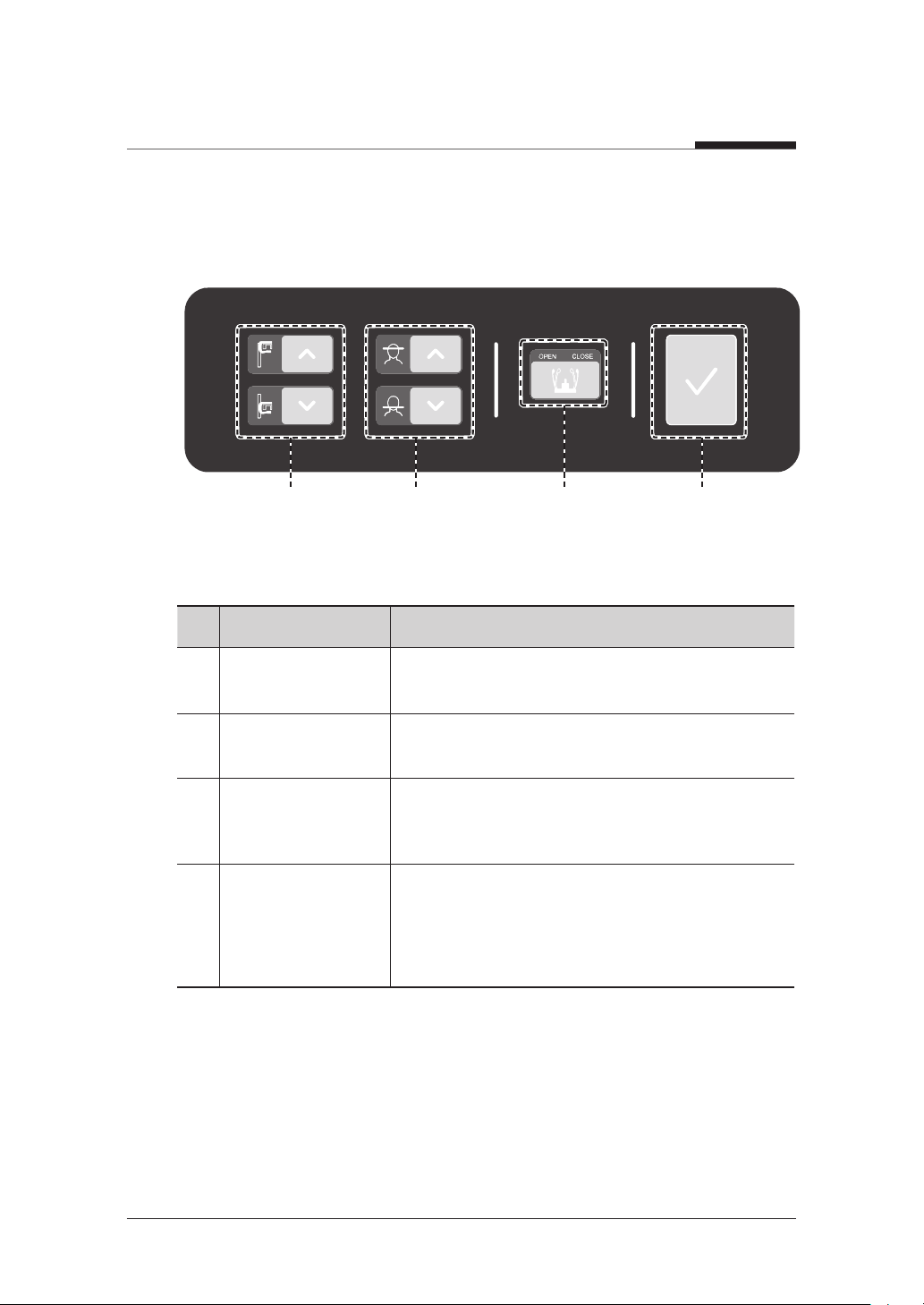
No. Button Description
Vertical Frame Up/
1
Down button
Horizontal Beam
2
Control button
Temple Support
3
OPEN/CLOSE
button
READY/ RETURN
4
button
Adjusts the vertical frame by moving vertically.
Positions the horizontal beam in PANO mode.
Adjusts the temple supports to position the patient.
When pressed, prepares for operation after
positioning the patient and configuring the
environment settings.
Initializes the positioning of the rotating unit.
PaX-i3D Smart
26 I
3. Imaging System Overview
3.3.2
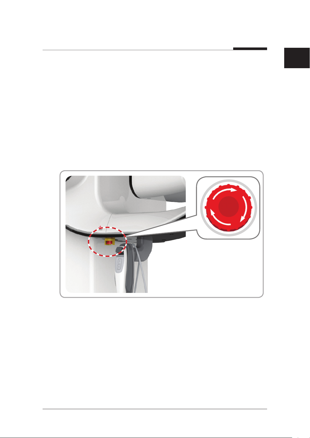
Emergency Stop Switch
During operation, the following emergency situations may occur:
● X-ray emission continues after the exposure switch has been released
● Injury to the patient or damage to the equipment
● Other emergency situations
If a problem occurs during image acquisition, press the red Emergency Stop Switch
to immediately stop the moving parts and cut off all power to the equipment’s electrical
components. To reset the Emergency Stop Switch, turn it clockwise until it pops up.
English
PaX-i3D Smart
27 I

3. Imaging System Overview
3.3.3
Exposure Switch
The exposure switch allows the operator to control image acquisition from outside of the
X-ray room.
Press and hold the exposure switch down until acquisition is complete. Premature release
of the exposure switch will abort image acquisition.
Pressing the exposure switch activates the orange indicator light to indicate that the X-ray
is being emitted.
Exposure Switch
X-ray Exposure LED
● Green: Standby (X-ray Off)
● Orange: Run (X-Ray On)
The exposure switch is detachable. Ensure the exposure switch cable is not
pulled out from the unit accidentally during operation.
PaX-i3D Smart
28 I
3. Imaging System Overview
3.3.4
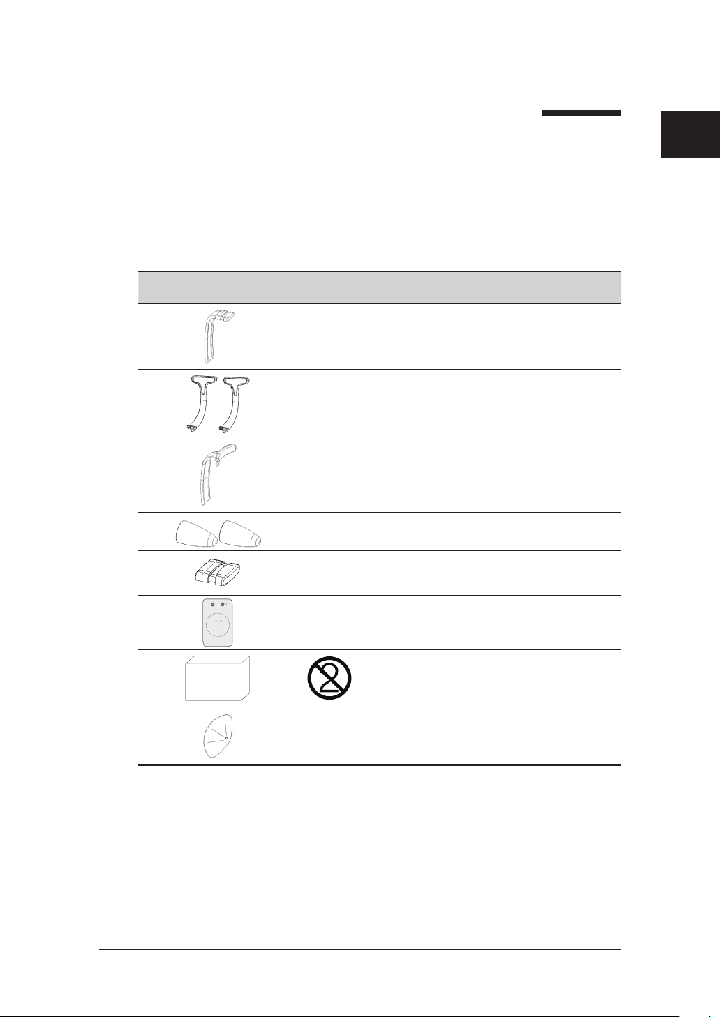
Enclosed Component
The enclosed components can be disassembled and cleaned. All enclosed components
that are used to support the patient(bite block, chin rest and temple supports) should be
cleaned with ethanol and wiped with clean towels.
Components Name and Function
Bite Block
Temple Supports (1 set)
Integrated Chin Rest: TMJ, Sinus
Ear Rod (1 set)
English
Panorama Cover
300 pcs
Nasal Positioner Cover (for CEPH)
Carpus Plate
Integrated Chin Rest Sanitary Vinyl
Covers (disposable): Bite Block
Protractor (1 set): Use to position the body in CEPH
mode.
PaX-i3D Smart
29 I


Imaging Software
4
Overview
4.1 PC Specifications ..................32
4.2 EasyDent / EzDent-i .............34
4.3 Console Software ..................35

4. Imaging Software Overview
Three programs come with this equipment to acquire, process, and view the image:
● EasyDent / EzDent-i: 2D viewer, analysis, and patient management
● Ez3D plus / Ez3D-i: 3D Viewer and analysis
● Console software: PANO / CEPH / CBCT
4.1
PC Specifications
● The PC system plays an important role in image processing and verification.
Configure the PC environment to meet the following specifications. If the PC
specifications are not met, the image quality may be low.
● Do not place patients near the equipment and PC.
Item HP LENOVO
CPU
RAM 16GB DDR3-1600 ECC RAM 16GB DDR3-1600 ECC RAM
Hard disk drive 1TB SATA 1st HDD 1TB SATA 1st HDD
Graphics board
Ethernet interface
Serial Port (RS232) HP Serial Port Adapter Kit 1 (On Board)
Power supply ≥ 600 Watts (90 % Efficiency) ≥ 610 Watts (85 % efficient)
Slots
Intel Xeon E5-1607 3GHz
1600 4C or Faster
NVIDIA Geforce GTX970 D5
4GB or greater
Broadcom 5761 Gigabit
Ethernet
2 PCI Express Gen3 x 16 slots
1 PCI Express Gen3 x 8 slot
1 PCI Express Gen2 x 8 slot
1 PCI Express Gen2 x 4 slot
1 PCI slot
Intel Xeon E5-1607 3GHz
1066 or Faster
NVIDIA Geforce GTX970 D5
4GB or greater
Intel 82579 Gigabit Ethernet
2 PCI Express Gen3 x 16 slot
1 PCI Express Gen3 x 16 slot
(x4 Electrical)
1 PCI Express Gen2 x 4 slot
1 PCI slot
PaX-i3D Smart
32 I

4. Imaging Software Overview
Item HP LENOVO
English
CD/DVD drive
Monitor
Operating system
Recommended
system
DVD-ROM, DVD+/-RW, BluRay
19” 1280 x 1024 screen
resolution
Windows 7 Professional
64-Bit
Z420 S30
DVD-ROM DVD R/W, Blu-Ray
R/W
19” 1280 x 1024 screen
resolution
Windows 7 Professional
64-Bit
PaX-i3D Smart
33 I

4. Imaging Software Overview
4.2
EasyDent / EzDent-i
EasyDent / EzDent-i is dental imaging software from Vatech Co. Ltd that manages
patient images so you can make faster, more accurate diagnoses. The console software
and 3D Viewer are linked with EasyDent / EzDent-i making it convenient for the user
to use and process necessary images. Various functions can be used so that acquired
images can be processed quickly and conveniently from the console software.
Please refer to 5.3 Creating New Patient and 5.4 Retrieving Patient
Information and EasyDent / EzDent-i User manual for more information.
Security Capabilities
● It is recommended to install and operate EasyDent/EzDent-i SW within
secure operating environment that allows only authorized users to access
and the system network is equipped with Window firewall built-in Windows
system, windows Defender antispyware tools and other commonly used 3rd
party security tools and application systems.
● The latest updates for anti-virus software and a firewall is recommended.
● The software can be updated by the manufacturer only. Unauthorized
software update through a third party, not the manufacturer, is strictly
prohibited. For cyber security issues related to the software and medical
devices, please contact the manufacturer.
PaX-i3D Smart
34 I

4. Imaging Software Overview
4.3
Console Software
Use the console software to configure the imaging environment according to the mode.
● To improve program functions, the console software may change without
notice.
The main screen of the Console Software consists of the following. Each one of the
different modes will be described later.
English
PaX-i3D Smart
35 I

4. Imaging Software Overview
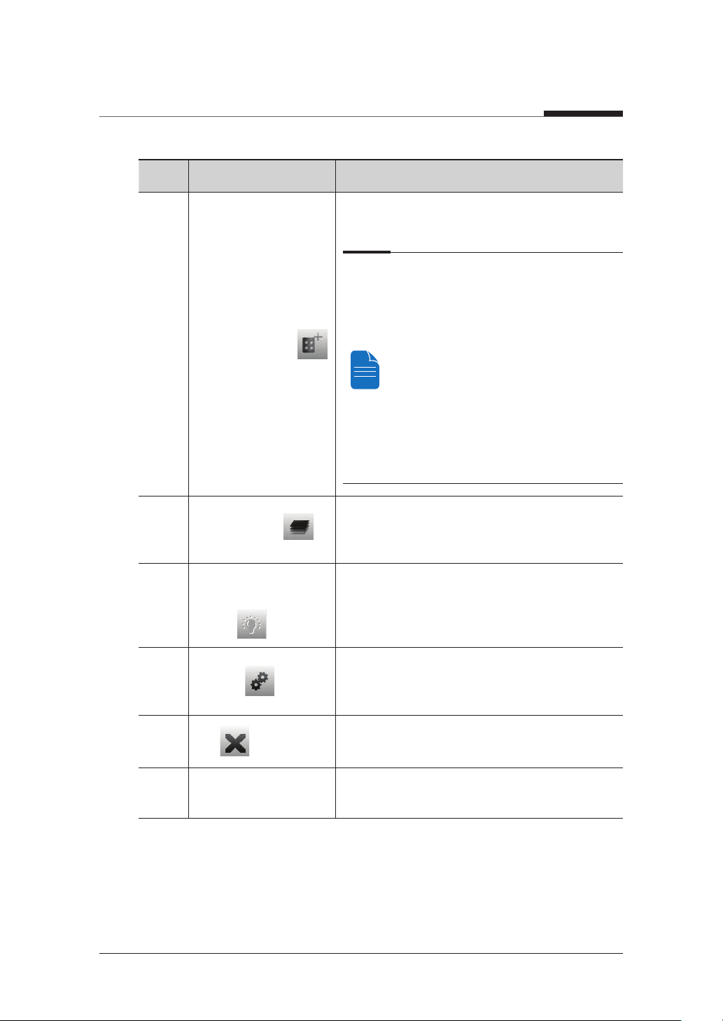
No. Function Description
1 Imaging Mode Display
This displays the current imaging mode.
● Indicates that the Magic PAN is
supported in the PANO imaging modality.
● Is displayed only for the Standard mode,
with the Magic PAN enabled.
Scanning Status and
2
Image Preview Window
3 Patient Information
4 Imaging Guide Window
Scan Time and DAP
5
Display Window
Tube Voltage and
6
Current Adjustment
This shows image acquisition progression in realtime.
This displays information about the selected
patient.
This displays various text instructions for the
operator to follow.
Upon clicking CONFIRM, the scan time and
estimated DAP value is displayed in this window.
If the patient is selected in EasyDent / EzDent-i,
the default kVp/mA according to the patient’s
information (gender/age) is displayed. This tool
adjusts the kVp and mA values or control the
power of the X-ray in order to improve image
quality. If necessary, adjust the kVp and mA
values manually using the arrows.
For the tube voltage and its correspondence
with the current patient, refer to Appendix >
13.1 Recommended X-ray Exposure Table.
PaX-i3D Smart
36 I

4. Imaging Software Overview
No. Function Description
English
This displays the current patient’s gender
as entered in EasyDent / EzDent-i’s patient
information. If necessary, gender can be
manually selected.
7 Patient Gender
8 X-ray intensity
Age Group / Gender VATECH’s Standard
Child ≤12
Man
Adult
Woman
This tool selects X-ray intensity.
Depending on the circumference of the
patient’s head, X-ray intensity may be
classified as Hard, Normal, or Soft :
Soft ≤ Normal ≤ Hard
Age
Average head
Group
circumference
Child 53±3 cm
Adult 56±3 cm
Range
(cm)
> 53±3 Hard
53±3 Normal
53±3 < Soft
> 56±3 Hard
56±3 Normal
56±3 < Soft
≥13
Classification
of head
circumference
PaX-i3D Smart
37 I
4. Imaging Software Overview
No. Function Description
9
Phantom Capture
This function is used when the Phantom Jig is
being used to acquire images.
Image acquisition using the Phantom Jig:
1. Click Phantom Capture Icon.
2. Select the Modality, followed by OK.
3. Check the parameters displayed in
the main GUI window. If correct, click the
‘Confirm’ button.
4. Align the Phantom Jig, and click the
‘Ready’ button.
5. Press and hold down the exposure
switch.
Manual Image
10
Reconstruction
Laser Beam On / Off
11
Button
12
Settings
13
Exit
14 Imaging Mode
If automatic reconstruction of the image fails, use
this function to reconstruct the image manually.
Select Modality and click Search Reconstruction.
Use this icon to turn the laser beam on or off for
patient positioning. This button is enabled when
the CONFIRM button is clicked after the imaging
environmental parameters are configured.
This Control Panel displays and sets various
equipment-related parameters, including
language, automatic save, DAP display unit, etc.
This button exits the capturing program.
This selects an imaging mode – PANO, CEPH or
CBCT.
PaX-i3D Smart
38 I
4. Imaging Software Overview
No. Function Description
English
After confirming all settings required for scanning,
press CONFIRM to apply the settings.
15 CONFIRM
16 READY
When you click CONFIRM, the scan
time and estimated DAP (Dose Area
Product) value will be shown on the
main display for the exposure you are
going to take.
This button is used when all aspects of
preparation have done for image acquisition
(including parameter settings and patient
positioning)
PaX-i3D Smart
39 I


5
Getting Started
5.1 Turning On Equipment ..........42
5.2 Running the Image Viewer ....44
5.3 Initiating the Console Software .
..............................................50

5. Getting Started
5.1
Turning On Equipment
● Do not place the patient close to the equipment is on. Doing so may cause
injury to the body and damage to equipment.
● Do not turn on the PC while the equipment is in operation. Doing so may
cause an error.
● Excessive temperature changes may cause condensation to form on the
equipment. When room temperature is reached, turn on the equipment.
● Equipment rebooting: After turning it off, the equipment may be turned on
again after 20 seconds.
● Warm-up the equipment for at least 5 minutes before the operation. For the
best image quality, it is recommended that equipment be warmed-up for 30
minutes or more.
If the equipment has not been used for a long time, please leave enough time
to warm-up the equipment. It extends the life of the x-ray tube.
The imaging system mainly consists of the imaging equipment and the PC.
Before turning on the equipment, please confirm the equipment and PC correctly
installed.
PaX-i3D Smart
42 I

5. Getting Started
1. Turn on the PC.
2. Press the switch that is located under the handle frame to turn on the equipment.
OFF (O)
ON ( I )
ON ( I )
3. Confirm the green LED light at the top of the equipment is on.
4. Plug the license key for the 3D viewer into the PC.
English
PaX-i3D Smart
43 I
License Key

5. Getting Started
5.2
Running the Image Viewer
EasyDent / EzDent-i is a basic imaging platform for all VATECH’s dental X-ray
equipments. The Imaging Program is interfaced with EasyDent / EzDent-i. On your
desktop, double-click EasyDent / EzDent-i icon. The EasyDent / EzDent-i main
window will be displayed.
For further details on this subject, refer to the EasyDent / EzDent-i user manual.
Security Capabilities
● It is recommended to install and operate EasyDent/EzDent-i SW within
secure operating environment that allows only authorized users to access
and the system network is equipped with Window firewall built-in Windows
system, windows Defender antispyware tools and other commonly used 3rd
party security tools and application systems.
● The latest updates for anti-virus software and a firewall is recommended.
● The software can be updated by the manufacturer only. Unauthorized
software update through a third party, not the manufacturer, is strictly
prohibited. For cyber security issues related to the software and medical
devices, please contact the manufacturer.
For PHT-30LFO dental computed tomography X-ray system, both 3D
Viewer(Ez3D plus/Ez3D-i) and console software are being accessed through
2D Viewer(EasyDent/EzDent-i) SW. 3D Viewer and console software do not
have image storage capability of its own and both programs will not be able to
patient information.
PaX-i3D Smart
44 I
5. Getting Started
5.2.1
Creating a New Patient Record
To create a new patient record, follow the procedure outline below:
EasyDent
❚
A. Click the Patient icon on the upper left corner of the EasyDent’s main GUI window.
English
PaX-i3D Smart
45 I

5. Getting Started
B. The following dialog box will open.
C. Enter the required patient information. Chart Number, First Name, and Last
Name are required fields which must be filled in. All other fields are optional, but it is
recommended that they be filled in.
D. Click Add to save the patient record.
EzDent-i
❚
A. Click the Add Patient icon from main GUI window.
B. Enter the required patient information. The Chart Number, E-Mail address, First
Name, and Last Name are required fields which must be filled in. (The chart number fills
in automatically.)
C. Click Add to save the patient record.
PaX-i3D Smart
46 I

5. Getting Started
Limit Access to Trusted Users Only
English
● EzDent software requires each operator to set up a unique user ID and
password to prevent any unauthorized access to patients’ confidential
information.
● User ID and password can be assigned to give permission to register,
add, delete and modify patient information and diagnostic images.
The application of User ID and password authentication assures the
accountability that the prescribed access process is being done by an
authorized user.
● According each operator’s privilege level, the login enables the user to
search, register, modify and delete the patient information or diagnostic
images. Different search criteria suggest availability of the patient information
being sought.
− Search by ID: Search by ID is possible if the patient id is known.
− Search by Name: Search by the name of the patient is possible.
− Search by age and gender can be used to divide the search result further,
for patients with the same name.
● The user’s Login/Logout time and work duration can be traced via log data.
PaX-i3D Smart
47 I

5. Getting Started
5.2.2
Retrieving Patient Records
EasyDent
❚
You can search through the patient database using a patient’s chart number, their first
name, or their last name.
A. On the Patient information pane, double-click the Chart No., First name, or Last
name of the patient and the virtual keyboard will pop up.
Double-click
B. Enter the Chart No., First name, or Last name of the patient by clicking the mouse
on the virtual key board and click the Enter (The physical keyboard can be used to do
the same job).
C. Patient information can be displayed on the Patient information pane and Patient
List.
PaX-i3D Smart
48 I
5. Getting Started
EzDent-i
❚
A. Enter the name or chart number of the patient to be searched on the Search pane
and then click the Search button. The information on the patient that fits the search
condition appears.
Enter
Double-click the Keyboard icon to display the virtual keyboard. You may search
patient information using the virtual keyboard.
English
B. Double-click the patient information to see more details about the patient as shown
below.
Double-click
PaX-i3D Smart
49 I

5. Getting Started
5.3
Initiating the Console Software
For a new patient, first register the patient information.
EasyDent
❚
A. First, click the patient information in the patient list, and click the Dental CT icon
(
) in the upper left corner of the EasyDent’s main window to open the imaging
program.
B. The following imaging program window opens. The sole purpose of this window is to
control equipment settings and acquire images.
PaX-i3D Smart
50 I

5. Getting Started
EzDent-i
❚
A. Search and select the patient to be captured.
B. Click Acquisition and the imaging mode (CT, Panorama, or Cephalo).
C. The main screen for the selected mode appears. (See 4.3 Imaging Software
Overview). From the main screen, you can configure the imaging parameter settings
prior to acquiring an image.
English
Please proceed to the next chapter.
Refer to chapters 6 - 8 for information regarding image acquisition.
51 I
PaX-i3D Smart


6
Acquiring PANO images
6.1 Setting Exposure Parameters ..
..............................................59
6.2 Patient Positioning ................63
6.3 X-ray Exposure ......................77
6.4 Finishing Scan .......................78
6.5 Confirming Image ..................78
6. Acquiring PANO images
To acquire PANO Images, first 5. Getting Started must be completed. If
5. Getting Started is not completed, you must go back to the 5. Getting Started and
finish the step first.
PANO Examination Program
Examination Arch Selection Examination Program
Standard
Right
Front
PANO
EXAMINATION
SPECIAL
EXAMINATION
Narrow, Normal,
Wide, Child ,
Orthogonal
-
Left
Bitewing*
Bitewing Incisor*
Bitewing Right*
Bitewing Left*
TMJ LAT Open
TMJ LAT Close
TMJ PA Open
TMJ PA Close
Sinus LAT
Sinus PA
* Bitewing examinations are available only when Orthogonal Arch is selected.
PaX-i3D Smart
54 I

6. Acquiring PANO images
Arch Selection
Examination Program Image
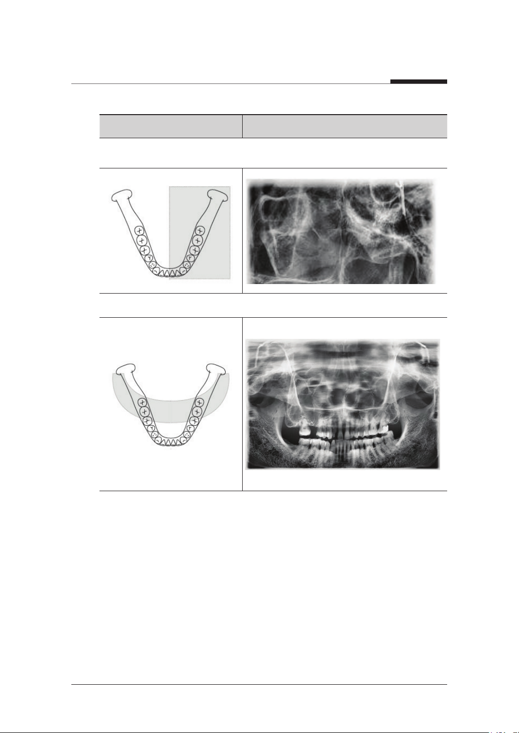
Narrow (Standard): Panoramic image of V-shaped palatal arches (small number of
adult females)
Normal (Standard): Panoramic image of normal adult palatal arches
English
Wide (Standard): Panoramic image of square-shaped palatal arches (some number of
adult males)
PaX-i3D Smart
55 I

6. Acquiring PANO images
Examination Program Image
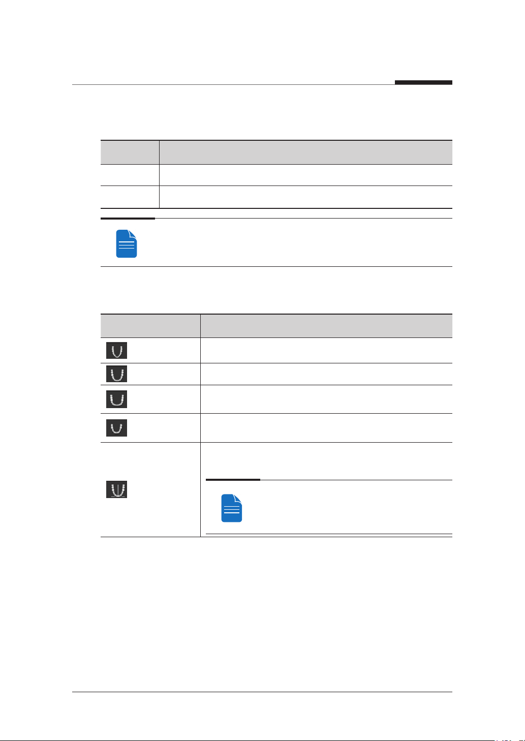
Child (Standard): Panoramic image of child palatal arches, 40% less x-ray dose than
in Normal mode.
Bitewing: Imaging from targeted areas of palatal arches; less x-ray dose than in
Standard mode.
PaX-i3D Smart
56 I

6. Acquiring PANO images
SPECIAL EXAMINATION
Examination Program Image
Orthogonal (Standard): Panoramic image where the x-ray angle enters vertically in
between the teeth so overlapping images are minimized.
TMJ LAT Open / Close: The acquired image focused on the lateral TMJ area.
English
TMJ PA Open / Close: The acquired image focused on the posterior-anterior TMJ
area.
PaX-i3D Smart
57 I
6. Acquiring PANO images
Examination Program Image
Sinus LAT: The acquired image focused on the lateral Maxillary Sinus area.
Sinus PA: The acquired image focused on the posterior-anterior Maxillary Sinus area.
PaX-i3D Smart
58 I

6. Acquiring PANO images
6.1
Setting Exposure Parameters
Perform the following procedures to select the capture parameters for the specific patient
and capture mode. Please refer to 4.3 Console Software for more information.
English
Without Magic PAN With Magic PAN
1. Click the PANO button.
2. Select a PANO option.
Mode Description
Normal This is the normal type.
Reconstruct an image with optimized focus (autofocus) from the
Magic PAN
(Optional)
entire panorama to acquire high quality images so any errors caused
by issues with the patient's position and tooth trajectory will be
minimized.
PaX-i3D Smart
59 I
6. Acquiring PANO images
3. (Optional) Select an Image option.
Mode Description
HD High Definition, High Resolution
Low Dose Normal Image
You can select an image option only when you have purchased Magic PAN
option. Default image option is HD.
4. Select Arch Selection.
Arch Selection Description
Narrow
Panoramic image of V-shaped palatal arches (small number
of adult females)
Normal Panoramic image of normal adult palatal arches
Wide
Child
Panoramic image of square-shaped palatal arches (some
number of adult males)
Panoramic image of child palatal arches, 40% less x-ray
dose than in Normal mode.
Panoramic image where the x-ray angle enters vertically in
between the teeth so overlapping images are minimized.
Orthogonal
5. Select an Examination Program.
If Orthogonal Arch is selected, four bitewing
examinations(bitewing, bitewing incisor, bitewing
right, bitewing left) are activated
PaX-i3D Smart
60 I

6. Acquiring PANO images
English
6. The gender of the patient is selected automatically. When necessary, it can be
selected manually.
7. Select x-ray intensity.
Depending on the circumference of the patient’s head, X-ray intensity may be
classified as Hard, Normal, or Soft :
Soft ≤ Normal ≤ Hard
Age
Group
Child 53±3 cm
Adult 56±3 cm
Average head
circumference
Range (cm)
> 53±3 Hard
53±3 Normal
53±3 < Soft
> 56±3 Hard
56±3 Normal
56±3 < Soft
Classification of head
circumference
8. The values of tube voltage and current are configured automatically according to
the patient's gender and x-ray intensity. Click the arrow button to zoom in. The
dose is adjustable by ±1 kVp and ±0.1 mA respectively.
9. Once the configuration has been completed, click the CONFIRM button.
PaX-i3D Smart
61 I

6. Acquiring PANO images
When you click CONFIRM button:
● The READY button will begin blinking to show that it has been activated.
● The Rotating unit will move to its initial scanning position.
● Three laser beams will be activated to make patient positioning easier.
● The Scan Time and DAP values will be shown on the Imaging Status Window.
10. Guide the patient to the equipment.
PaX-i3D Smart
62 I

6. Acquiring PANO images
6.2
Patient Positioning
English
● Have patients, especially pregnant women and children, wear a lead apron
to protect them from residual radiation.
● Be careful not to direct the laser beam into the patient's eyes. Doing so can
result in a permanent loss of vision.
● Correct posture reduces the shadow cast by the patient's cervical spine and
allows for clear image acquisition.
● Metal implants or bridges may reduce the quality of the images.
● If the laser beam is not correctly positioned, distortion, where the image may
be enlarged or reduced, or ghost shadows may occur and lower the image
quality so please be careful.
In general, images are acquired when the patient is standing. In special cases,
a chair without a backrest (stool) may be used. Do not obstruct the laser beam
or the operation of the equipment with the chair.
Getting prepared
1. Ask the patient to remove all the metal objects (glasses, earrings, hair pins, braces,
false teeth). Metal objects may induce ghost images and lower the image quality.
2. Ask the patient to wear a lead apron to protect them from residual radiation.
3. Use the Vertical Frame Up/Down button or switch option to adjust the equipment
to match the height of the patient.
PaX-i3D Smart
63 I

6. Acquiring PANO images
6.2.1
Pano Standard Mode
Patient Positioning
1. Insert the bite block into the chin rest then cover with a sanitary vinyl cover.
Sanitary Vinyl Cover
Bite Block
Bite Block Lock/Unlock Knob
The sanitary vinyl cover is for single use only. It should be
replaced after each patient. Be sure to use the approved vinyl
cover.
Clean the chin rest and bite block with ethanol and wipe with a dry towel
before the next patient.
2. Use the Temple Support Open/Close button on the control panel to widen the
temple supports.
3. Guide the patient to the inside of the equipment.
4. Use the Vertical Frame Up/Down button or switch option to adjust the height of
the equipment so the patient's chin reaches the chin rest.
PaX-i3D Smart
64 I
6. Acquiring PANO images
5. Guide the patient to stand in the center of the equipment and direct them to remain
in the position outlined below.
● Two hands: Hold the handles of the equipment tightly.
● Chest: Press against the equipment.
● Two feet: Keep both feet close to the inside of the base.
● Shoulders: Keep your shoulders relaxed and balanced.
● Cervical Spine: Straighten your body and stand still.
6. Direct the patient to correctly bite into the bite block groove with their front teeth.
7. Turn the knob to fix the bite block in place.
8. Direct the patient to maintain the posture as described below.
● Mouth: Close your mouth.
● Tongue: Touch the roof of your mouth.
● Two eyes: Close your eyes.
Mid-sagittal plane
laser beam
Frankfurt plane laser
beam
Canine laser beam
English
Edentulous Patient Positioning
1. Remove the bite block from the chin rest.
2. Use the Temple Support Open/Close button on the control panel to widen the
temple supports.
PaX-i3D Smart
65 I

6. Acquiring PANO images
3. Guide the patient to the inside of the equipment.
4. Use the Vertical Frame Up/Down button or switch option to adjust the height of the
equipment so the patient's chin reaches the chin rest.
5. Guide the patient to stand in the center of the equipment and direct them to remain
in the position outlined below.
● Two hands: Hold the handles of the equipment tightly.
● Chest: Press against the equipment.
● Two feet: Keep both feet close to the inside of the base.
● Shoulders: Keep your shoulders relaxed and balanced.
● Cervical Spine: Straighten your body and stand still.
6. Direct the patient to maintain the posture as described below.
● Mouth: Close your mouth.
● Tongue: Touch the roof of your mouth.
● Two eyes: Close your eyes.
PaX-i3D Smart
66 I

6. Acquiring PANO images
Correct posture reduces the shadow cast by the patient's cervical spine and
allows for clear image acquisition.
During image acquisition, direct the patient to maintain the posture as
described below.
● Two hands: Hold the handles of the equipment tightly.
● Chest: Press against the equipment.
● Two feet: Keep both feet close to the inside of the base.
● Shoulders: Keep your shoulders relaxed and balanced.
● Cervical Spine: Straighten your body and stand still.
● Mouth: Bite the bite block and close your mouth.
● Tongue: Touch the roof of your mouth.
● Two eyes: Close your eyes.
Ask the patient to maintain their position and to not move until the image
acquisition is completed.
English
Laser Beam Positioning
Be careful not to shine the laser beam directly into the person's eyes.
Doing so may result in vision loss.
If the laser beam is not correctly positioned, distortion, where the image may be
enlarged or reduced, or ghost shadows may occur and lower the image quality.
Be sure to align the laser beam properly.
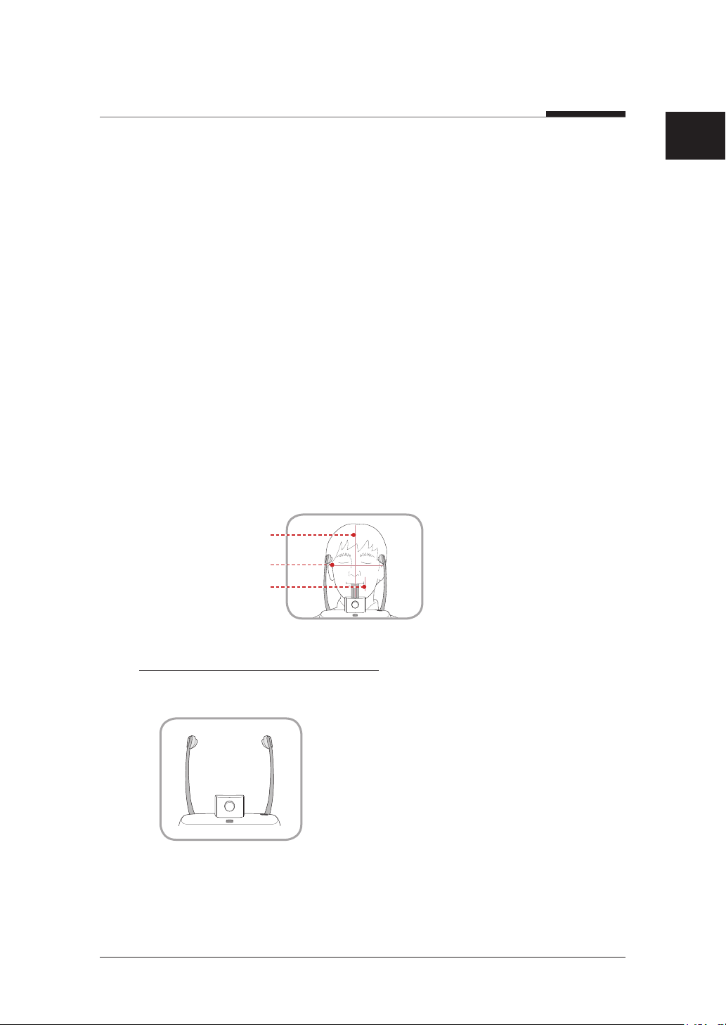
1. Align the vertical beam with the center of the face. (To prevent horizontal expansion
of the image)
PaX-i3D Smart
67 I

6. Acquiring PANO images
2. Align the horizontal beam in a straight line with the Frankfurt line on the patient's
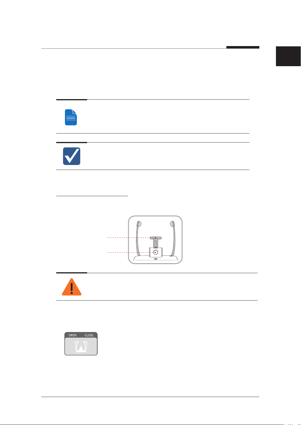
face. Use the Horizontal Beam button on the control panel to position it. Check to
see that the horizontal beam aligns with the patient's face horizontally.
Mid-sagittal plane
laser beam
Frankfurt plane laser
beam
Canine laser beam
Frankfurt plane laser
beam UP button
Frankfurt plane laser
beam DOWN button
3. Direct the patient to smile and align the canine teeth beam with the center of the
canines. Use the Canine Teeth Beam level to adjust the position of the beam.
Canine laser
Canine
Teeth Beam
beam lever
Finishing Patient Positioning
1. After checking the positions of the patient and the laser beam, click the Temple
Support Open/Close button on the control panel to prevent the patient's head
from moving.
2. Click the READY button. The x-ray exposure has not started yet.
3. Now go to 6.3 X-ray Exposure to begin operation.
PaX-i3D Smart
68 I
6. Acquiring PANO images
6.2.2
TMJ Open Mode
Acquire the TMJ Close image after the TMJ Open image has been acquired.
Steps for TMJ Mode
TMJ Open positioning > Align Laser Beam > X-ray Exposure > TMJ Close
positioning > Align Laser Beam > X-ray Exposure
Clean the chin rest and bite block with ethanol and wipe with a dry towel
before the next patient.
TMJ Open Positioning
1. Insert the integrated chin rest into the equipment.
English
Chin support
Lock / release knob for
bite block
Clean the chin rest with ethanol and wipe with a dry towel before the next
patient.
2. Use Temple Support Open/Close button on the control panel to widen temple
supports.
3. Guide the patient to the inside of the equipment.
PaX-i3D Smart
69 I

6. Acquiring PANO images
4. Use the Vertical Frame Up/Down button or switch option to adjust the height of
the equipment so the patient's chin reaches the chin rest.
5. Guide the patient to stand in the center of the equipment and direct them to remain
in the position outlined below.
● Two hands: Hold the handles of the equipment tightly.
● Chest: Press against the equipment.
● Two feet: Keep both feet close to the inside of the base.
● Shoulders: Keep your shoulders relaxed and balanced.
● Cervical Spine: Straighten your body and stand still.
6. Lower the integrated chin rest to the bottom and turn the knob to fix it.
7. Guide the patient to press the base of their nose (acanthion point) against the chin
rest and tilt their head forward about -5˚. At this point, make sure the patient's jaw
does not to touch the equipment.
If the jaw touches the equipment it is difficult to maintain the proper position
to get good images.
Be careful the patient does not to touch the equipment with their jaw.
8. Direct the patient to maintain the posture as described below.
● Mouth: After swallowing once, open your mouth as wide as possible.
● Tongue: Touch the roof of your mouth.
● Two eyes: Close your eyes.
● As shown in the picture, the
support unit of the integrated
chin rest should touch the
patient's acanthion point.
● Ask the patient to maintain
their position until the
operation is completed.
PaX-i3D Smart
70 I

6. Acquiring PANO images
Laser Beam Positioning
Be careful not to shine the laser beam directly into the person's eyes.
Doing so may result in vision loss.
If the laser beam is not correctly positioned, distortion, where the image may be
enlarged or reduced, or ghost shadows may occur and lower the image quality.
Be sure to align the laser beam properly.
1. Align the vertical beam with the center of the face. (To prevent horizontal expansion
of the image)
2. Align the horizontal beam in a straight line with the Frankfort line on the patient's
face. Use the Horizontal Beam button on the control panel to position it.
Check to see that the horizontal beam aligns with the patient's face horizontally.
3. Align the Canine Teeth Beam with the center of the patient's canines. Use the
Canine Teeth Beam level to adjust the position of the beam.
English
Mid-sagittal plane
laser beam
Frankfurt plane laser
beam
Canine Teeth Beam
PaX-i3D Smart
71 I
Canine laser
beam lever

6. Acquiring PANO images
Finishing Patient Positioning
1. After checking the positions of the patient and the laser beam, click the Temple
Support Open/Close button on the control panel to prevent the patient's head
from moving.
2. Click the READY button. The x-ray exposure has not started yet.
3. Now go to 6.3 X-ray Exposure to begin operation.
6.2.3
TMJ Close Mode
Acquire the TMJ Close image after the TMJ Open image has been acquired.
Steps for TMJ Mode
TMJ Open positioning > Align Laser Beam > X-ray Exposure > TMJ Close
positioning > Align Laser Beam > X-ray Exposure
Correct posture reduces the shadow cast by the patient's cervical spine and
allows for clear image acquisition.
TMJ Close Positioning
1. After TMJ Open image is acquired, a "Do you want to take the TMJ Close image
continuously?" message is displayed. Press the Confirm button to begin TMJ Close
Mode.
2. Lower the integrated chin rest to the bottom and turn the knob to fix it.
3. Guide the patient to press the base of their nose (acanthion point) against the chin
rest and tilt their head forward about -5˚. At this point, make sure the patient's jaw
does not to touch the equipment.
PaX-i3D Smart
72 I

6. Acquiring PANO images
If the jaw touches the equipment it is difficult to maintain the proper position to
get good images.
Be careful the patient does not to touch the equipment with their jaw.
4. Direct the patient to maintain the posture as described below.
● Mouth: After swallowing once, open your mouth as wide as possible.
● Tongue: Touch the roof of your mouth.
● Two eyes: Close your eyes.
English
● As shown in the picture, the
support unit of the integrated
chin rest should touch the
patient's acanthion point.
● Ask the patient to maintain
their position until the
operation is completed.
Laser Beam Positioning
This is the same as for TMJ Open mode.
Finishing Patient Positioning
This is the same as for TMJ Open mode.
PaX-i3D Smart
73 I

6. Acquiring PANO images
6.2.4
Sinus Mode
Patient Positioning
1. Insert the integrated chin rest into the equipment.
Clean the chin rest with ethanol and wipe with a dry towel before the next
patient.
2. Use Temple Support Open/Close button on the control panel to widen temple
supports.
3. Guide the patient to the inside of the equipment.
4. Use the Vertical Frame Up/Down button or switch option to adjust the height of
the equipment so the patient's chin reaches chin rest.
5. Guide the patient to stand in the center of the equipment and direct them to remain
in the position outlined below.
● Two hands: Hold the handles of the equipment tightly.
● Chest: Press against the equipment.
● Two feet: Keep both feet close to the inside of the base.
● Shoulders: Keep your shoulders relaxed and balanced.
● Cervical Spine: Straighten your body and stand still.
6. After adjusting the integrated chin rest, turn the knob to fix the chin rest.
PaX-i3D Smart
74 I

6. Acquiring PANO images
7. Position the integrated chin rest so it rests directly under the patient's lower lip.
8. Direct the patient to maintain the posture as described below.
● Head: Tilt the head back 10˚ - 15˚.
● Mouth: Close your mouth.
● Tongue: Touch the roof of your mouth.
● Two eyes: Close your eyes.
Ask the patient to maintain their
position until the operation is
completed.
English
PaX-i3D Smart
75 I

6. Acquiring PANO images
Laser Beam Positioning
Be careful not to shine the laser beam directly into the person's eyes.
Doing so may result in vision loss.
If the laser beam is not correctly positioned, distortion, where the image may be
enlarged or reduced, or ghost shadows may occur and lower the image quality.
Be sure to align the laser beam properly.
1. Align the vertical beam with the center of the face. (To prevent horizontal expansion
of the image)
2. Tilt the patient's head back 10˚ - 15˚ then align the horizontal beam with tip of the
nose. Use the Horizontal Beam button on the control panel to position it.
3. Align the Canine Teeth Beam with the center of the patient's canines. Use the
Canine Teeth Beam level to adjust the position of the beam.
Finishing Patient Positioning
1. After checking the positions of the patient and the laser beam, click the Temple
Support Open/Close button on the control panel to prevent the patient's head
from moving.
2. Click the READY button. The x-ray exposure has not started yet.
3. Now go to 6.3 X-ray Exposure to begin operation.
PaX-i3D Smart
76 I

6. Acquiring PANO images
6.3
X-ray Exposure
After the aligning the laser beam, the x-ray scan can begin.
The user must comply with the laws of the country regarding the usage of the
medical equipment.
Direct the patient to close their eyes during operation.
To acquire optimized images, direct the patient to hold their breath and to not
swallow. Also, direct them to not move.
1. Direct the patient to close their eyes.
2. Close the door when leaving the x-ray room. Observe the patient during operation
and check the imaging status.
3. Begin acquisition by pressing the exposure switch. Continue to press the exposure
switch until the image has been acquired.
English
Orange: X-ray On
4. Release the exposure switch when “Image capturing is completed” message
appears on the screen.
PaX-i3D Smart
77 I

6. Acquiring PANO images
During x-ray exposure, the status appears as follows.
● The exposure switch LED light is orange.
● The exposure switch LED light on top of the equipment is orange.
● An alert will sound to indicate that x-ray emission is currently underway.
● In the console software, the x-ray On in yellow changes.
6.4
Finishing Scan
1. Open the temple supports and guide the patient out of the equipment.
2. Remove the hygiene cover from the bite block.
3. Press
6.5
Confirming Image
Acquired images can be reconstructed and converted to DICOM format.
The exported images can be confirmed in EasyDent / EzDent-i.
1. The images are transferred to EasyDent / EzDent-i automatically.
2. The images are automatically saved if automatic save is configured in the basic
settings. If automatic save is not configured in the basic settings, click the Save to
DB button to save the images.
3. Double-click the image to confirm in the Patient list.
(Return) button to bring the Rotating Unit back to its initial position.
Please refer to the EasyDent / EzDent-i User manual for more information.
PaX-i3D Smart
78 I

7
Acquiring CEPH images
7.1 Setting Exposure Parameters ...
..............................................82
7.2 Patient Positioning ................85
7.3 X-ray Exposure ......................95
7.4 Finishing Scan .......................96
7.5 Confirming Image ..................96

7. Acquiring CEPH images
To acquire images, 5. Getting Started should be completed first. If 5. Getting Started
is not completed, return to that section and finish the step first.
CEPH Imaging Software
❚
Examination Image Description
● The radiation is directed from the
posterior of the skull to the anterior.
● Use to examine cranial diseases,
trauma and congenital malformations.
● Used to assess the growth of lateral
side of the face. It is also useful to
examine the ramus mandibulae, the
posterior region of the third largest
PA
<Scan CEPH>
molar in the lower jaw, and the side
wall of the maxillary sinus, and the
frontal sinus, antrum ethmoidale,
olfactory pits and optic disc pits.
Lateral
<OneShot CEPH>
<Scan CEPH>
<OneShot CEPH>
● Measure the angles formed by the
connecting lines between the cranial
measurement points to further assess
the growth of the facial region. It is
widely used in Orthodontics and Oral
and Maxillofacial Surgery.
● Study craniofacial disease, trauma
and congenital malformation and
examine the soft tissue in the
otorhinolaryngological area, sinus and
hard palate.
● Measure the angles formed by the
connecting lines between the cranial
measurement points to further assess
the growth of the facial region. It's
widely used in Orthodontics and Oral
and Maxillofacial Surgery.
PaX-i3D Smart
80 I

7. Acquiring CEPH images
Examination Image Description
Use to study the base of the skull,
horizontal angulation of the mandibular
condylar axis, sphenoidal sinus,
SMV
<Scan CEPH>
Waters
View
<OneShot CEPH>
curvature of the lower jaw, side wall of
the maxillary sinus, and zygomatic arch
fractures. Also useful to study the inner
and outer alar plates and holes at base
of the skull.
Use to study the frontal sinus,
antrum ethmoidale, optic disc pit,
frontozygomatic suture, nasal cavity,
coronoid process between the upper jaw
and zygomatic arch.
English
CARPUS
<OneShot CEPH>
81 I
Use to assess hand bone age and
compare with changes in the skull.
PaX-i3D Smart

7. Acquiring CEPH images
7.1
Setting Exposure Parameters
Perform the following procedures to select the capture parameters for the specific patient
and capture mode. Please refer to 4.3 Console Software for the more information.
Steps for Configuring Imaging Conditions
❚
ex) SC Sensor(Xmaru2301CF) ex) OP Sensor(1210SGA)
1. Click the CEPH button.
2. Select the examination program under Ceph Examination
3. (For One-shot CEPH only) Do the selections that follow.
— FOV Size: Select the FOV size.
FOV Details Model
Large
: 12x10 (inches)
: 30.48x25.40 (cm)
Full size OP(1210SGA)
PaX-i3D Smart
82 I

7. Acquiring CEPH images
FOV Details Model
English
Medium
: 9x10 (inches)
: 22.86x25.40 (cm)
Small
: 8x8 (inches)
: 20.32x20.32 (cm)
— Exposure Time: Scan time can be adjusted by resolution of 0.1 sec in the range of
0.7 sec to 1.2 sec.
4. The gender of the patient is selected automatically. When necessary, it can be
selected directly.
5. Select x-ray intensity.
Region of the no interest of the rear
part of the head is eliminated to
minimize the X-ray exposure area.
For Child OP(1210SGA)
OP(1210SGA)
/ OS(910SGA)
/ OS(910SGA)
Depending on the circumference of the patient’s head, X-ray intensity may be
classified as Hard, Normal, or Soft :
Soft ≤ Normal ≤ Hard
Age
Group
Child 53±3 cm
Adult 56±3 cm
Average head
circumference
PaX-i3D Smart
83 I
Range (cm)
> 53±3 Hard
53±3 Normal
53±3 < Soft
> 56±3 Hard
56±3 Normal
56±3 < Soft
Classification of head
circumference

7. Acquiring CEPH images
6. The values of tube voltage and current are configured automatically according to
the patient's gender and x-ray intensity. Click the arrow button to zoom in. The
dose is adjustable by ±1 kVp and ±0.1 mA respectively.
7. Once the configuration has been completed, click the CONFIRM button.
When you click CONFIRM button:
● The READY button will begin blinking to show that it has been activated.
● The Scan Time and DAP values will be shown on the Imaging Status Window.
8. Guide the patient to the equipment.
PaX-i3D Smart
84 I
7. Acquiring CEPH images
7.2
Patient Positioning
English
● Have patients, especially pregnant women and children, wear a lead apron
to protect them from residual radiation.
● Be careful not to direct the laser beam into the patient's eyes. Doing so can
result in a permanent loss of vision.
● Metal implants or bridges may reduce the quality of the images.
● If the laser beam is not correctly positioned, distortion, where the image may
be enlarged or reduced, or ghost shadows may occur and lower the image
quality so please be careful.
● Ensure that the nasal positioner left unfolded, before adjusting the ear rods in
the proper direction.
Correct positioning is an important factor in capturing the best possible image.
Although the illustrations and explanations on patient’s posture and device
usage are based on the OS / OP models (one shot-type sensor), those for the
SC (scan type) model should be the same.
PaX-i3D Smart
85 I

7. Acquiring CEPH images
Getting Prepared
❚
1. Ask the patient to remove all the metal objects (glasses, earrings, hair pins, braces,
false teeth). Metal objects may induce ghost images and lower the image quality.
2. Ask the patient to wear a lead apron to protect them from residual radiation.
3. Use the Vertical Frame Up/Down button or switch option to adjust the equipment
to match the height of the patient.
7.2.1
Lateral / Full Lateral Mode
Full Lateral mode is available for SCAN CEPH model only.
1. Leave enough space between the ear rods.
Ear Rod
Use the Porion position
reference indicator that appears
in the acquired image to easily
Porion position reference indicator
2. Guide the patient to the CEPH unit.
3. Direct the patient to relax their neck and shoulders and stand upright.
confirm the location of Porion.
PaX-i3D Smart
86 I

7. Acquiring CEPH images
4. Use the Vertical Frame Up/Down button or switch option to adjust the height of
the CEPH Unit to approximately match the height of the patient.
5. During operation, properly align the ear rods with the patient's ears so their head
does not move.
After adjusting the height of the column, align the ear rods and nasal positioner
with the patient.
English
6. Align horizontally so the patient's Frankfort line is parallel with the floor.
7. Direct the patient to swallow first before closing their mouth and to remain in their
current position until image acquisition is complete.
8. Click the READY button. The x-ray exposure has not started yet.
9. Now go to 7.3 X-ray Exposure to begin operation.
PaX-i3D Smart
87 I

7. Acquiring CEPH images
7.2.2
Frontal (PA) mode
1. Rotate the ear rods 90° clockwise from their initial position as shown in the figure
Nasal Positioner
Ear Rod
Porion position
reference indicator
2. Fold the nasal positioner up. The nasal positioner is not used in Frontal mode.
3. Guide the patient to the CEPH unit.
4. Ask the patient to stand upright facing the sensor. Make sure that the patient’s
Use the Porion position
reference indicator that
appears in the acquired
image to easily confirm the
location of Porion.
shoulders are level and that his/her neck is relaxed.
PaX-i3D Smart
88 I
7. Acquiring CEPH images
5. Use the Vertical Frame Up/Down button or switch option to adjust the height of
the CEPH Unit to approximately match the height of the patient.
6. During operation, properly align the ear rods with the patient's ears so their head
does not move.
After adjusting the height of the column, align the ear rods and nasal positioner
with the patient.
7. Align horizontally so the patient's Frankfort line is parallel with the floor.
English
8. Direct the patient to swallow first before closing their mouth and to remain in their
current position until image acquisition is complete.
9. Click the READY button. The x-ray exposure has not started yet.
10. Now go to 7.3 X-ray Exposure to begin operation.
PaX-i3D Smart
89 I
7. Acquiring CEPH images
7.2.3
SMV Mode
1. Rotate the ear rods 90° clockwise from their initial position as shown in the figure.
Nasal Positioner
Ear Rod
Porion position
reference indicator
2. Fold the nasal positioner up. The nasal positioner is not used in Frontal mode.
3. Guide the patient to the CEPH unit.
4. Guide the patient to face the X-ray tube and stand upright.
Use the Porion position
reference indicator that
appears in the acquired
image to easily confirm
the location of Porion.
PaX-i3D Smart
90 I

7. Acquiring CEPH images
5. Use the Vertical Frame Up/Down button or switch (option) to adjust the height of
the CEPH Unit to match the height of the patient.
6. During operation, properly align the ear rods with the patient's ears so their head
does not move.
After adjusting the height of the column, align the ear rods and nasal positioner
with the patient.
7. Carefully tilt the patient's head back and adjust so their Frankfort line is parallel with
the floor.
8. Direct the patient to swallow first before closing their mouth and to remain in their
current position until image acquisition is complete.
Frankfurt plane
English
9. Click the READY button. The x-ray exposure has not started yet.
10. Now go to 7.3 X-ray Exposure to begin operation.
PaX-i3D Smart
91 I
7. Acquiring CEPH images
7.2.4
Waters View Mode
1. Rotate the ear rods 90° clockwise from their initial position as shown in the figure.
Nasal Positioner
Ear Rod
Porion position
reference indicator
2. Fold the nasal positioner up. The nasal positioner is not used in Frontal mode.
3. Guide the patient to the CEPH unit.
4. Ask the patient to stand upright facing the sensor. Make sure that the patient’s
5. Use the Vertical Frame Up/Down button or switch option to adjust the height of
6. During operation, properly align the ear rods with the patient's ears so their head
Use the Porion position
reference indicator that
appears in the acquired
image to easily confirm
the location of Porion.
shoulders are level and that his/her neck is relaxed.
the CEPH Unit to approximately match the height of the patient.
does not move.
After adjusting the height of the column, align the ear rods and nasal positioner
with the patient.
PaX-i3D Smart
92 I

7. Acquiring CEPH images
7. Direct the patient to swallow and close their mouth, and guide the patient's head
back 30˚ - 40˚. Direct the patient to remain in the current position until image
acquisition is complete.
30-40
8. Click the READY button. The x-ray exposure has not started yet.
9. Now go to 7.3 X-ray Exposure to begin operation.
7.2.5
CARPUS Mode
Installing the Carpus Plate
❚
English
1. Align the end of the nasal positioner to the carpus plate groove so it is attached to
the nasal positioner.
Locking bolt
Nasal positioner
Fixed bolt
Notch
CARPUS Plate
PaX-i3D Smart
93 I
 Loading...