


(PHT-60CFO)
User Manual
Version 1.5.0
E n g l i s h


PaX-i3D Green (PHT-60CFO) User Manual
Notice
Notice
Thank you for purchasing the
PaX-i3D Green
The
TM
is an advanced digital dental diagnostic system that
PaX-i3D Green
TM
extra-oral imaging system.
incorporates PANO, CEPH, and 3D CT imaging capabilities into a single
system.
This manual describes how to operate the
PaX-i3D Green
TM
system. It is
recommended that you thoroughly familiarize yourself with this manual in order
to make the most effective use of this equipment.
Observe all cautions, safety messages and warnings which appear in this
manual.
The QR code linked to video le about image capture for the
CEPH Lateral
and
is provided in the manual. The smart phone and pad which
PANO Standard
have the QR code reader application program can be used to watch video.
Due to a constant technological improvement, the manual may not contain
the most updated information, subjecting to change without prior notice to the
persons concerned. For further information not covered in this manual, please
contact us at:
VATECH Co., Ltd.
Phone: +82-1588-9510
E-mail: gcs@vatech.co.kr
This document is originally written in English.
The PaX-i3D Green
Manual Name: PaX-i3D Green
Version: 1.5.0
Publication Date: 2016-05
TM
is referred to as Equipment in this manual.
TM
(Model: PHT- 60CFO)
05

PaX-i3D Green (PHT-60CFO) User Manual
Table of Contents
Table of Contents
Notice ......................................................
1
1.1
1.2
1.3
2.
2.1
2.2
2.3
2.4
3
3.1
General Information ....................................... 12
Manufacturer's Liability ........................................................ 12
Owner and Operator's Obligations ...................................... 12
Conventions in this Manual ................................................. 13
Warnings and Precautions ............................16
General Safety Precautions ................................................. 16
Electricity-related Safety Precautions .................................. 20
Radiation Safety .................................................................. 21
Warnings ............................................................................. 22
PaX-i3D Green Imaging System Overview ... 26
Introduction .......................................................................... 26
05
3.1.1 System Components.............................................................26
3.1.2 Features ................................................................................26
3.1.3 The PaX-i3D Green Model Series (Optional)........................28
3.1.4 Standards and Regulations...................................................29
3.2
3.3
3.3.1 Control Panel ........................................................................33
3.3.2 Touch Screen ........................................................................34
3.3.3 Emergency Stop Switch ........................................................39
3.3.4 The Exposure Switch ............................................................39
3.3.5 Components and Positioning Accessories ............................40
3.4
06
Imaging System Structure ................................................... 30
General View of the PaX-i3D Green .................................... 31
Marks and Symbols ............................................................. 41

PaX-i3D Green (PHT-60CFO) User Manual
Table of Contents
4
4.1
4.2
4.3
4.3.1 PANO .................................................................................... 50
4.3.2 CEPH ...................................................................................55
4.3.3 CBCT ...................................................................................57
5
5.1
5.2
5.2.1 Creating a New Patient Record ............................................65
5.2.2 Retrieving Patient Records ...................................................67
5.3
Software Overview ......................................... 44
PC System Requirements (Recommended) ....................... 44
EasyDent / EzDent-i ............................................................ 45
Imaging Software Overview ................................................. 46
Getting Started ............................................... 64
Turning on the PaX-i3D Green ............................................ 64
Running the Image Viewer .................................................. 65
Initiating the Imaging Program ............................................. 69
6
6.1
6.2
6.3
6.3.1 PANO Standard and Bitewing mode ..................................... 82
6.3.2 TMJ Open .............................................................................86
6.3.3 TMJ Close ............................................................................89
6.3.4 Sinus .....................................................................................90
6.4
7
7.1
7.2
7.2.1 Lateral / Full Lateral ............................................................101
7.2.2 Frontal (PA) ......................................................................... 102
Acquiring PANO Images ................................ 72
PANO Imaging Program ...................................................... 72
Setting Exposure Parameters .............................................. 77
Positioning the Patient ......................................................... 81
Initiating X-ray Exposure ..................................................... 93
Acquiring CEPH Images ................................ 96
Setting the Exposure Parameters ........................................ 96
Positioning the Patient ....................................................... 100
7.2.3 SMV ....................................................................................104
07

PaX-i3D Green (PHT-60CFO) User Manual
Table of Contents
7.2.4 Waters View ........................................................................105
7.2.5 CARPUS .............................................................................106
7.3
8
8.1
8.2
8.3
8.3.1 Starting imaging with the SCOUT feature ...........................121
8.3.2 SCOUT Viewer ...................................................................123
8.4
9
10
10.1
10.2
Initiating X-ray Exposure ................................................... 107
Acquiring CT Images ................................... 112
Setting the Exposure Parameters .......................................11 2
Positioning the Patient ........................................................116
Acquiring a SCOUT Image ................................................ 121
Initiating X-ray Exposure ................................................... 124
Troubleshooting ........................................... 128
Cleaning and Maintenance .......................... 130
Cleaning ............................................................................ 130
Maintenance ...................................................................... 131
10.2.1 Regular Maintenance ..........................................................131
10.2.2 Maintenance Task Checklis ................................................132
11
12
12.1
12.2
12.3
12.4
Disposing of the Unit ................................... 134
Technical Specications .............................. 136
Mechanical Specications ................................................. 136
Technical Specications .................................................... 140
Electrical Specications ..................................................... 145
Environmental Specications ............................................ 145
08

PaX-i3D Green (PHT-60CFO) User Manual
Appendices
Table of Contents
1
2
2.1
2.2
2.3
3
Recommended X-ray Exposure Table ........ 148
X-ray Dose Data ............................................ 150
DAP Table .......................................................................... 150
X-ray Leakage Dose .......................................................... 152
X-ray Scatter Dose ........................................................... 153
Electromagnetic Compatibility (EMC)
Information .................................................... 156
4
Acquiring image for the pediatric dental
patient ............................................................ 161
4.1
4.2
Age group: classication table .......................................... 161
Positioning the pediatric dental patient ............................. 161
4.3
4.4
5
Setting exposure values to the age group ........................ 162
The references pertinent to the potential risks for the pediatric
patients ............................................................................. 162
Abbreviations ............................................... 164
09


1
General Information
1.1
1.2
1.3
Manufacturer's Liability ........................................................ 12
Owner and Operator's Obligations ...................................... 12
Conventions in this Manual ................................................. 13

PaX-i3D Green (PHT-60CFO) User Manual
1 General Information
1 General Information
1.1
Manufacturer's Liability
The manufacturers and/or retailers of this equipment assume responsibility for
the safe and normal operation of this product
■The equipment has been installed by a VATECH authorized technician.
■The equipment has been installed in accordance with all of the cautions and
conditions for installation.
■Genuine VATECH approved equipment and components have been used
at all times.
■All maintenance and repairs have been performed by a VATECH authorized
agent.
■The equipment has been used normally in accordance with the user's
manual.
■The equipment damage or malfunction is not the result of an error on the
part of the owner or operator.
only when:
1.2
Owner and Operator's Obligations
■The owner of this equipment shall perform constancy tests at regular intervals in
■The owner of this equipment shall perform regular inspection and maintenance of
12
order to ensure patient and operator safety. These tests must be performed in
accordance with local X-ray safety regulations.
the mechanical and electrical components in this equipment to ensure safe and
consistent operation (IEC 60601-1). The owner of this equipment shall ensure
inspection and cleaning works are performed in accordance with the maintenance
schedule outlined in
Chapter 10 Cleaning and Maintenance.

PaX-i3D Green (PHT-60CFO) User Manual
1 General Information
1.3
Conventions in this Manual
The following symbols are used throughout this manual. Make sure that you
fully understand each symbol and follow the instructions which accompany it.
To prevent personal injury and/or damage to the equipment, please observe all
warnings and safety information included in this document.
WARNING
CAUTION
X-ray
Indicates information that should be followed
with the utmost care. Failure to comply with a
warning may result in severe damage to the
equipment or physical injury to the operator
and/or patient.
Indicates a situation that demands prompt
and careful action, a specific remedy, or
emergency attention.
Indicates a possible danger of exposure to
radiation.
IMPORTANT
NOTE
SINGLE USE
Indicates a situation or action that could
potentially cause problems to the equipment
and/or its operation.
Emphasizes important information or provide
useful tips and hints.
Indicates a component which must be replaced
for each new patient.
13


2
Warnings and Precautions
2.1
2.2
2.3
2.4
General Safety Precautions ................................................. 16
Electricity-related Safety Precautions .................................. 20
Radiation Safety .................................................................. 21
Warnings ............................................................................. 22

PaX-i3D Green (PHT-60CFO) User Manual
2 Warnings and Precautions
WA
G
2. Warnings and Precautions
Be sure to strictly observe all warnings and safety
RNIN
instructions included in this manual.
2.1
General Safety Precautions
Operator qualications
This equipment may only be operated by personnel fully trained in its operation.
■To operate this equipment, all operators must:
-have read and understood the user's manual
-be familiar with the fundamental structure and functions of this equipment
-be able to recognize irregularities in the operation of this equipment and
implement appropriate measures to remedy such irregularities.
General safety precautions
■Follow the instructions specied in this manual to ensure the safety of both
the patient and the operator.
■The operator must maintain visual contact with the patient at all times during
imaging.
16
■Do not open or remove the cover panels on this equipment. Always have
a trained and authorized service technician carry out inspection and
maintenance of this equipment.
■Do not place foreign objects on this equipment at any time.
■Do not place any objects within this equipment's eld of operation.
■Do not push or pull the equipment. If equipment overbalances, resulting in
the risk of physical injuries or property damage.
■Operators must ask the patient to remain still until the equipment arm has
stopped moving and the reset motion is complete.

PaX-i3D Green (PHT-60CFO) User Manual
2 Warnings and Precautions
CAUTION
■Observe all local re regulations. Always keep a re extinguisher near the
equipment.
■The operator of this equipment must be familiar with this equipment's
emergency protocols.
■Ensure that this equipment is kept away from water, moisture, or foreign
substances at all times.
■If this product is exposed to water, moisture, or a foreign substance,
immediately turn off all power to the equipment and contact your VATECH
technical support representative.
■Immediately cease all operation of this equipment if there are signs of oil
leakage and contact you VATECH technical support representative.
Ventilation
■Do not obstruct the equipment's ventilation for air opening. Improper
ventilation could result in the equipment overheating due to a lack of air
circulation.
■Do not spray any type of liquid or aerosol on this equipment as this
may penetrate the system and damage the electrical and mechanical
components inside.
■Always leave a sufcient amount of space around the PC to allow for proper
ventilation.
Hygiene
Always disconnect the equipment from the power outlet
when disinfecting the surfaces of the equipment.
■All removable patient support components (bite block, chin support, temple
supports) can be cleaned using alcohol-based cleaning solutions.
■Patient support handles can be cleaned using alcohol-based cleaning
solutions.
■Other surfaces of the equipment, including the touch screen, can be
cleaned using a soft cloth dampened with a mild cleaning solution.
17

PaX-i3D Green (PHT-60CFO) User Manual
2 Warnings and Precautions
■Disinfect the components (bite block, temple supports etc.) of the equipment
■New hygiene cover must be provided for each new patient to prevent the
IMPORTANT
Condensation
■Extreme fluctuations in temperature may cause condensation to develop
that come into contact with the patient or the operator after each exposure.
transmission of communicable disease.
Do not use aerosol or spray cleaning agents directly on the
surface of the equipment.
inside the equipment. Do not turn on the equipment until it has reached
room temperature.
Cooling
■ Allow the proper amount of cool down time (for the X-ray tube to cool down)
to elapse between each image acquisition.
-Mode of operation: Continuous operation with intermittent loading.
-Exposure time: Max. 20.2 s / Resting time: 5 min.
-Column operation time: 1 min / Resting time: 9 min
■ If the temperature inside the tube head reaches 60 °C, X-ray exposure will
cease and an error message will be displayed. Normal X-ray capabilities will
resume after the generator reaches 58 °C (136.4 ℉).
■ If the fan (optional) is installed, it operates automatically when the
temperature surrounding the tube head reaches the pre-dened level: 40 ℃
(104 ℉). The set point temperature is congurable.
Turning the equipment on / adjusting the height of the equipment
■Do not position the patient in the equipment while it is initiating as the
patient could be injured if the equipment malfunctions.
■Ensure that the patient is kept clear of the mechanism while adjusting the
18
height of the equipment.

PaX-i3D Green (PHT-60CFO) User Manual
2 Warnings and Precautions
Emergency stop
■If a problem occurs during image acquisition, press the red emergency
stop button to immediately stop all moving parts and cut off all power to the
equipment.
Trouble-free operation
■ Never use this equipment in an environment that is susceptible to explosion.
■ Always operate the equipment within a temperature range of 10 °C to 35 °C
(50 ℉ to 95 ℉) for the safe operation. Image quality may deteriorate if the
equipment is operated outside of this range.
■ Always allow the equipment sufcient time to warm up (while switched on) if
it has been exposed to temperatures of below 10 °C (50 ℉).
■ Only perform X-rays of patients if system is in full working order.
■ Always ensure that equipment movement is not obstructed by the patient’s
clothing, medical device (such as a wheelchair), or the patient themselves.
■ Do not leave the patient unattended around the equipment.
■ Remove all radio-controlled devices, mobile phones, etc. from the X-ray
room prior to image acquisition as these objects may cause the equipment
to malfunction.
Modifying the equipment
■Modifying the equipment in any way which may affect the safety of the
operator, patient or other persons is prohibited by law.
■No part of this equipment is serviceable by the user. All maintenance
and repair of this equipment must be performed by a qualified service
technician.
■This product may only be operated with original VATECH accessories or
third-party accessories expressly approved by VATECH.
19

PaX-i3D Green (PHT-60CFO) User Manual
2 Warnings and Precautions
2.2
Electricity-related Safety Precautions
■Check the status of the power source, PC and cables prior to operating the
equipment.
■Ensure that the on/off switch is set to off when the equipment is not in use.
■Always disconnect the power supply before cleaning the equipment.
■Always keep electrical cords away from hot appliances or radiators.
■DO NOT place the PC or peripheral equipment connected to the PC in the
immediate vicinity of the patient.
■The equipment and PC should be connected to a common protective earth.
■Never overload the equipment’s circuit by sharing it with too many
appliances.
■Use the same power circuit for the PC and the equipment.
Combining this equipment with other devices
■Do not connect this equipment to devices which are not part of the system.
■Do not connect this equipment to a Multiple Portable Socket-Outlet (MPSO)
or extension cord.
Electromagnetic compatibility
■The PaX-i X-ray unit complies with IEC standard 60601-1-2.
■Medical electrical equipment is subject to special EMC preventive
measures. It must be installed and operated as specied in the
Requirements
■If high-voltage systems, radio link systems or MRI systems are located
within 5 m of the unit, please observe the specifications stated in the
installation requirements.
■Portable and mobile RF communications equipment may interfere with
medical electrical equipment. Therefore, the use of mobile wireless phones
in medical ofces or hospital environments must be prohibited.
document.
Installation
20

PaX-i3D Green (PHT-60CFO) User Manual
2 Warnings and Precautions
WA
G
WA
G
For more details, refer to the document Electromagnetic Compatibility
Information.
ElectroStatic Discharge
Connector pins or sockets bearing ESD warning labels must not be touched or
interconnected without observing ESD protective measures.
2.3
Radiation Safety
RNIN
■The operator must remain outside a shielded room during X-ray exposure in
order to protect himself/herself from radiation.
■The patient must wear a lead apron with neck and thyroid protection during
X-ray exposure.
■Children and pregnant women must consult with a doctor before X-ray
exposure.
■This equipment must be housed inside an X-ray shielded room.
■During imaging; the operator must maintain visual contact with the patient
from outside the shielded area.
Since rules and regulations concerning radiation safety
differ between countries, it is the responsibility of the
owner and/or operator of this equipment to comply with
all applicable rules and regulations concerning radiation
safety and protection in their area.
■The operator should continuously check the status of the patient and the
equipment during imaging.
■The operator must immediately stop imaging if the equipment malfunctions.
As a manufacturer of radiology equipment that conforms
to stringent protection standards around the world, we
RNIN
guarantee the maximum degree of protection against
radiation hazards for our equipment.
21

PaX-i3D Green (PHT-60CFO) User Manual
2 Warnings and Precautions
WA
G
WA
G
WA
G
2.4
Warnings
The following warning statements should be obeyed with the utmost care.
Failure to follow these warnings may cause severe damage to the equipment or
physical injuries to the patient and/or operator.
RNIN
RNIN
X-ray equipment is hazardous to patient and the operator
if proper exposure safety measures and/or operating
instructions are not observed.
It is important to read this user manual carefully and
strictly abide by all warnings and cautions stated within it.
● 3D image should not be used for screening examinations.
Each exam must be justified by demonstrating that the
benets outweigh the risk.
● Where it is likely that evaluation of soft tissues will be
required as part of the patient’s radiological assessment,
conventional medical CT or MR should be used instead of
dental cone beam imaging.
RNIN
● PaX-i3D Green system, like other medical equipment,
uses high-frequency electrical signals that can interfere
with implantable devices such as pacemakers and
implantable cardioverter-debrillators(ICDs). If the patient
has such an implantable device, you should be aware of
any interference in its operation and immediately power
off the Dental X-ray system.
● PaX-i3D Green system is designed to withstand the
effects of defibrillation. However, when possible,
disconnect the Dental X-ray systems during debrillation
since a malfunction of the safety controls could otherwise
result in electrical burns for the patient.
22

PaX-i3D Green (PHT-60CFO) User Manual
2 Warnings and Precautions
CAUTION
Lasers
■The system incorporates Class 1 laser products. The light localizers used
in this product are intended for correct patient positioning and must not be
used for any other purpose.
■For maximum safety, advise the patient not to look directly at the laser
beam.
■While adjusting the patient, ensure that the laser beam is not directed at the
patient’s eyes.
Risk of eye injury!
Do not use this equipment with any other laser sources
and do not make any changes to the settings or processes
that are described in these operating instructions.
Cleaning
■Never expose this equipment to liquids, mists or sprays. Exposing this
equipment to liquids may cause an electrical shock or otherwise damage
the system.
■Do not use spray cleaners on this equipment, as this could cause a re.
During Operation
■Never use this equipment in an environment that is susceptible to explosion.
■Do not place ammable materials near this equipment.
■Do not operate the PC or Touch screen while the equipment is performing
an operation. Failure to comply with this instruction may result in system
malfunction.
■Immediately stop imaging if the equipment malfunctions in any way.
■If a problem occurs during imaging, press the red emergency stop button to
immediately stop all moving parts and cut off all power to the equipment’s
electrical components.
■Never touch the patient while also touching the SIP/SOP connectors.
23

PaX-i3D Green (PHT-60CFO) User Manual
2 Warnings and Precautions
In case of electrical re
■Use only re extinguishers designed for electrical res to extinguish res on
■Liquid extinguishers, such as those which use water, could damage the
■Unplug the equipment’s power cable before extinguishing any re.
Installation
■In order to avoid improperly balanced equipment, install the device on a at
■If the equipment is not stable, property damage and/or personal injury may
■Do not push or pull the equipment.
■Equipment should only be installed by an authorized technician, complying
this equipment.
equipment and/or cause injury.
surface to maintain stability.
occur.
with proper installation procedures.
24

3
PaX-i3D Green Imaging System Overview
3.1
3.1.1 System Components.............................................................26
3.1.2 Features ................................................................................26
3.1.3 The PaX-i3D Green Model Series (Optional)........................28
3.1.4 Standards and Regulations...................................................29
3.2
3.3
3.3.1 Control Panel ........................................................................33
3.3.2 Touch Screen ........................................................................34
3.3.3 Emergency Stop Switch ........................................................39
3.3.4 The Exposure Switch ............................................................39
3.3.5 Components and Positioning Accessories ............................40
3.4
Introduction .......................................................................... 26
Imaging System Structure ................................................... 30
General View of the PaX-i3D Green .................................... 31
Marks and Symbols ............................................................. 41

PaX-i3D Green (PHT-60CFO) User Manual
3 PaX-i3D Green Imaging System Overview
3 PaX-i3D Green Imaging System Overview
3.1
Introduction
PaX-i3D Green
The
incorporates Panoramic (PANO), Cephalometric (CEPH), and 3D CT imaging
capabilities into a single system.
PaX-i3D Green
The
cephalometric and CT image of the oral and craniofacial anatomy to provide
diagnostic information for adult and pediatric patients. The
system uses the advanced sensors to produce the higher quality of image in 2D
and 3D of the head region, including the dental/maxillofacial regions.
PaX-i3D Green
The
professionals who are licensed to perform X-rays by the law of the region in
which it is being used.
is an advanced digital dental diagnostic system that
system is intended for use to take a panoramic,
may only be used by dentists, X-ray technicians and other
3.1.1 System Components
■PaX-i3D Green digital X-ray equipment
■PC
PaX-i3D Green
■EasyDent / EzDent-i: 2D viewer and patient management software
■Ez3D plus / Ez3D-i: 3D viewer
■Imaging software
3.1.2 Features
■A 3-in-1 imaging solution: PANO, CEPH and CBCT imaging combined in
single equipment.
■Improved image processing algorithms:
-Magic PAN (Optional): A high quality image reconstructed from the optimal
auto-focused images in each segment throughout the panoramic region to
correct the improper patient positioning and rotating unit’s trajectory.
■Metal Artifact Reduction: Metal artifacts are minimized to improve image quality.
26

PaX-i3D Green (PHT-60CFO) User Manual
3 PaX-i3D Green Imaging System Overview
■Fast CEPH: CEPH imaging with low X-ray dose and high speed
■Control Panel: to allow an easy handling of the equipment
■Multi-FOV (Field Of View): FOV is selected, based on the most suitable
ROI.
■Provides an auto-switching between 2 sensors for the PANO and CBCT
imaging, without the intervention of the operator.
■3D Viewer
Ez3D plus / Ez3D-i:
Enables 3D images to be analyzed
accurately, leading to greater diagnostic precision.
■DICOM le support: The standard le format for medical applications.
27

PaX-i3D Green (PHT-60CFO) User Manual
3 PaX-i3D Green Imaging System Overview
3.1.3 The PaX-i3D Green Model Series (Optional)
Model Item Sensor FOV (mm)
PANO Xmaru1501CF -
SP
SC
OP
PANO+CBCT
PANO+CBCT
+CEPH
PANO+CBCT
+CEPH
Xmaru1215CF MP 100 X 80, 80 X 80, 80 X 50, 50 X 50
CT
Xmaru1524CF MP
PANO Xmaru1501CF -
Xmaru1215CF MP 100 X 80, 80 X 80, 80 X 50, 50 X 50
CT
Xmaru1524CF MP
CEPH Xmaru2301CF Scan Type
PANO Xmaru1501CF -
Xmaru1215CF MP 100 X 80, 80 X 80, 80 X 50, 50 X 50
CT
Xmaru1524CF MP
CEPH 1210SGA
160 X 100, 120 X 90, 80 X 80, 80 X 50, 50 X 50
150 X 150, 120 X 90, 80 X 80, 80 X 50, 50 X 50
160 X 100, 120 X 90, 80 X 80, 80 X 50, 50 X 50
150 X 150, 120 X 90, 80 X 80, 80 X 50, 50 X 50
160 X 100, 120 X 90, 80 X 80, 80 X 50, 50 X 50
150 X 150, 120 X 90, 80 X 80, 80 X 50, 50 X 50
One shot Type
12 X 10, 9 X 10, 8 X 8 (inches)
30.48x25.40, 22.86x25.40, 20.32x20.32(cm)
28

PaX-i3D Green (PHT-60CFO) User Manual
3 PaX-i3D Green Imaging System Overview
0434
3.1.4 Standards and Regulations
Standards:
The PaX-i3D Green is designed and manufactured to meet the following
standards:
IEC/EN/UL 60601-1, IEC/EN 60601-1-1, IEC/EN 60601-1-2, IEC/EN 60601-13, IEC/EN 60601-2-7, IEC/EN 60601-2-28, IEC/EN 60601-2-32, IEC/EN 606012-44, ISO 9001, ISO 13485
NEMA standard publication PS 3.1-3.18, 2008
X-ray source assembly [DG-07C11T2 / DG-07C11C1] IEC 60601-2-28 (1993)
The CE symbol grants this equipment compliance with the European
Directive for Medical Devices 93/42/EEC as amended by 2007/47/EC as a
class IIb device.
UL symbol grants this equipment compliance with the UL 60601-1 / CAN/
CSA C22.2 No.601.1
Classications (IEC60601-1 6.1):
Protection against the ingress of water: Ordinary Equipment: IPX0
Protection against electric shock: Class 1 equipment, Type B Applied Parts
29

PaX-i3D Green (PHT-60CFO) User Manual
3 PaX-i3D Green Imaging System Overview
NOTE
3.2
Imaging System Structure
RS232 Interface Cable 10 m (32.8’)
1. Signal input/output at the column up/down switch (optional)
External equipment intended for connection to signal
input, signal output or other connectors, shall comply with
relevant IEC Standard (e.g., IEC60950 for IT equipment
and IEC60601-1series for medical electrical equipment). In
addition, all such combination-system-shall comply with
the standard IEC60601-1 and/or IEC60601-1-1 harmonized
national standard or the combination.
30

PaX-i3D Green (PHT-60CFO) User Manual
3 PaX-i3D Green Imaging System Overview
3.3
General View of the PaX-i3D Green
31

PaX-i3D Green (PHT-60CFO) User Manual
3 PaX-i3D Green Imaging System Overview
NOTE
No. Item Details
CEPH imaging sensor (optional).
1 X-ray SENSOR (CEPH)
- 1-1. One shot Type
- 1-2. Scan Type
- Positions the patient during CEPH imaging.
2 NASAL POSITIONER
- The ruler for use to compensate the acquired image that is
different from actual size.
3 EAR RODS
SECONDARY
4
COLLIMATOR
5 X-ray TUBE
6 TEMPLE SUPPORTS
7 ROTATING UNIT
X-ray SENSOR
8
(PANO / CT)
9 CHINREST
10 CONTROL PANEL
Secure the patient’s head during CEPH imaging.
Limits the X-ray irradiation eld for CEPH scanning.
The source of X-ray emission.
Support the patient’s temples during PANO scan.
Rotates around the patient’s head during exposure (depending
on the imaging mode).
Sensors: used for CT and PANO imaging.
This module consists of two different sensors that perform
different functions (CT and PANO). When you select a scanning
mode, the sensor will be switched automatically (CT ↔ PANO,
and vice versa).
Supports the patient’s chin during imaging.
Allows the operator to control certain functions of the equipment
and displays operational parameters.
For more details, refer to
3.3.1 Control Panel
3.3.2 Touch
and
Screen
11 HANDLE FRAME
12 TELESCOPIC COLUMN
13 STATIONARY COLUMN
14 BASE
32
Held firmly by the patient during imaging to stabilize his / her
position.
Moves the column up or down for patient positioning.
The portion of the column xed to the base.
Used to balance and stabilize the equipment.
The structural overview of the PaX-i3D Green may differ
depending on the model. For more information, refer to
section “3.1.3 The PaX-i3D Green Model Series”.
PaX-i3D Green (PHT-60CFO) User Manual
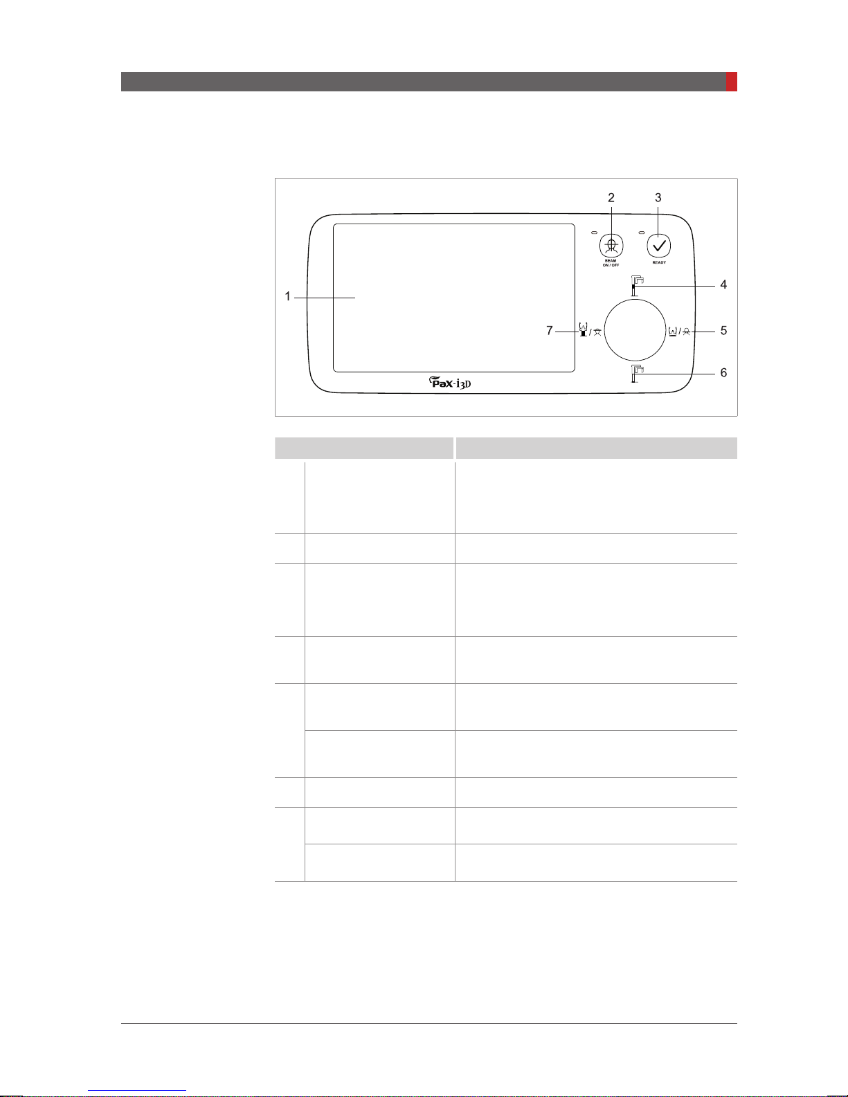
3.3.1 Control Panel
Buttons Functions
1
Touch Screen
3 PaX-i3D Green Imaging System Overview
Configures the parameter settings in each
imaging mode. For more information on this,
refer to
3.3.2 Touch Screen.
2
Laser Beam ON / OFF Turns ON or OFF the laser beams.
Indicates that parameter settings and the
3
READY
4
Column UP Moves the column up.
Chinrest DOWN
5
Frankfurt plane laser
beam DOWN
6
Column DOWN Lowers the column.
Chinrest UP
7
Frankfurt plane laser
beam UP
patient alignment are nished and imaging is
ready.
Lowers the chinrest.
- Functions only in the CT imaging mode.
Moves Frankfurt plane laser beam down
- Functions only in the PANO imaging mode.
Moves the chinrest up.
- Functions only in the CT imaging mode.
Moves Frankfurt plane laser beam up.
- Functions only in the PANO imaging mode.
.
33
PaX-i3D Green (PHT-60CFO) User Manual
3 PaX-i3D Green Imaging System Overview
CAUTION
3.3.2 Touch Screen
You can congure the parameter settings in each mode using the touch screen.
touch screen
The
Imaging Software Overview)
display the same parameter settings.
Never use pointed objects, such as a ballpoint pen or pencil,
to manipulate the LCD screen as they could scratch or
damage the LCD screen.
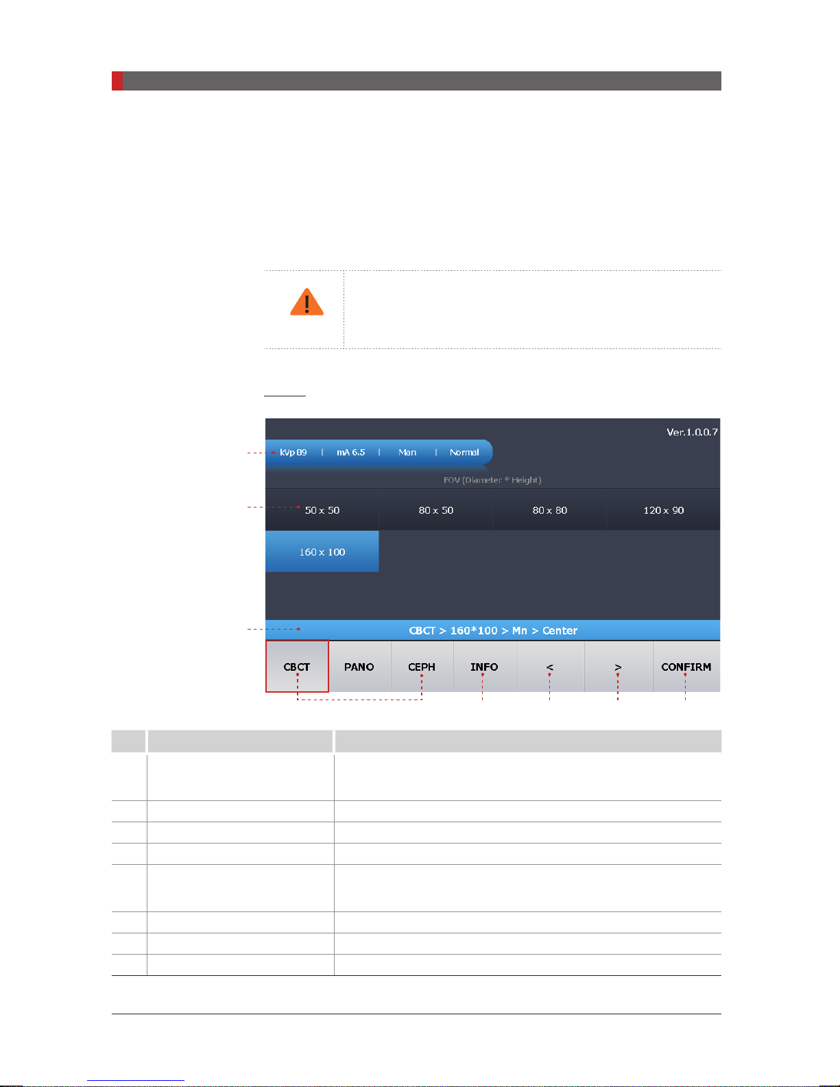
CBCT
1
on the equipment and
on the PC are synchronized in real time, and
the imaging program (See 4.3
2
3
4 5 6 7 8
No. Function Description
Imaging parameter settings
1
information
2
FOV selection Shows the CT sensor model mounted.
3
Selection settings Displays the current selections in sequential order.
4
Imaging mode selection Select the imaging mode.
5
INFO
Displays currently set information such as patient type and
X-ray setting values.
Enables the user to set a patient’s gender and X-ray intensity
and controls kVp / mA.
6
Back Moves to the previous level
7
Forward Moves to the next level
8
CONFIRM Click this button when the parameter settings are nished.
34
PaX-i3D Green (PHT-60CFO) User Manual
3 PaX-i3D Green Imaging System Overview
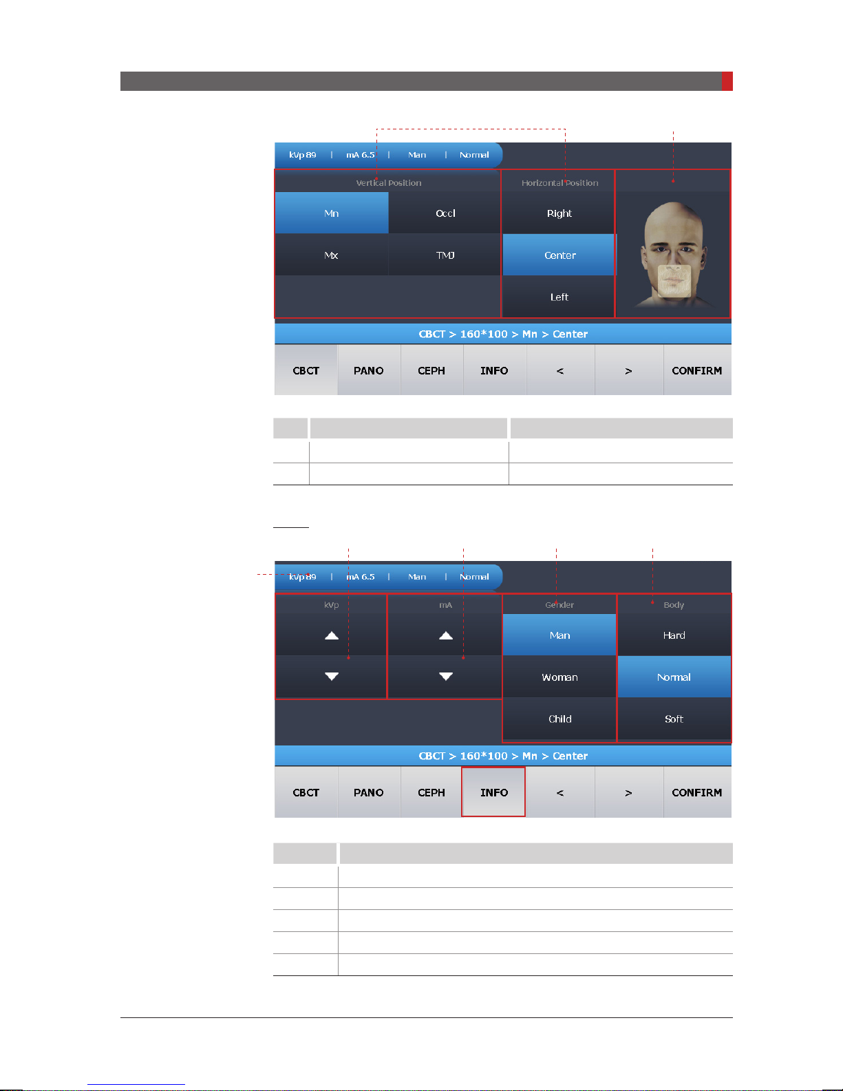
1 2
No. Function Description
1
Examination area selection Selects the tooth position
2
Guidance Image _
INFO
1 2 3 4
5
No. Function
1
2
3
4
5
Tube voltage UP / DOWN
Tube current UP / DOWN
Patient’s gender selection
Patient’s X-ray intensity selection
Displays the parameter settings
35
PaX-i3D Green (PHT-60CFO) User Manual
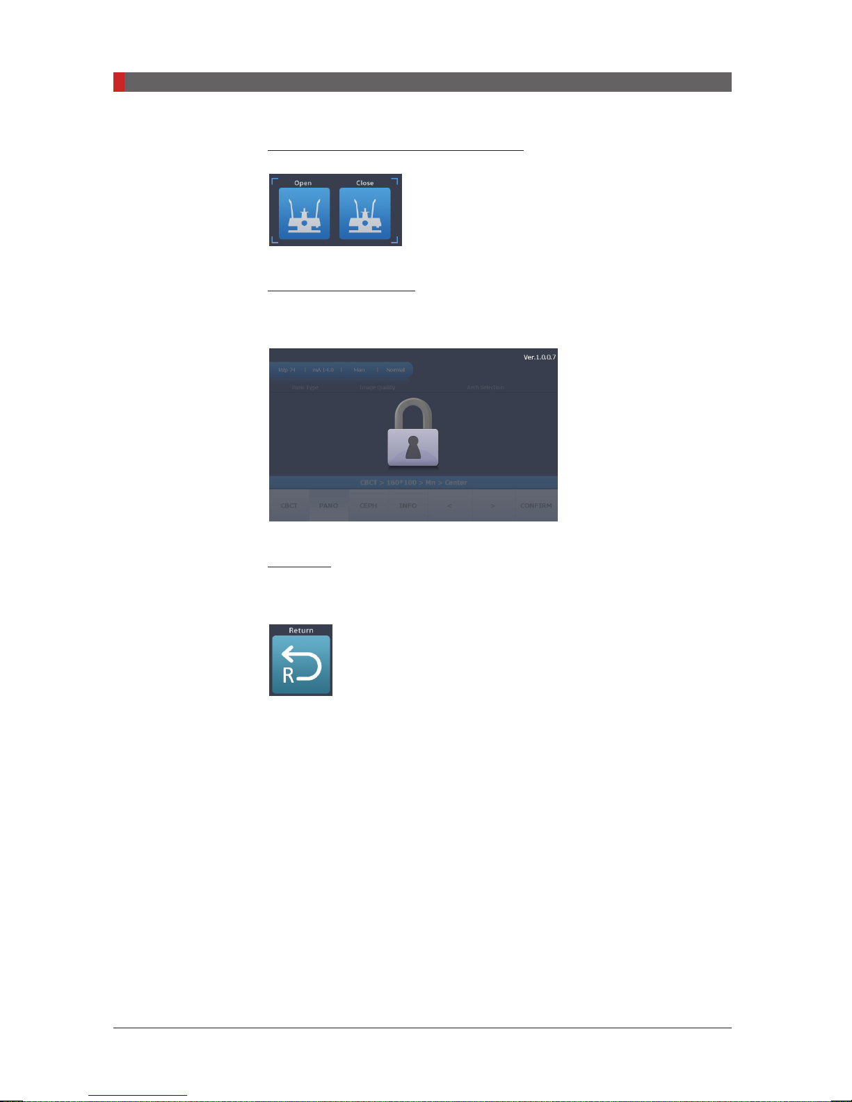
3 PaX-i3D Green Imaging System Overview
Temple Support Adjustment Button
Touch Screen LOCK
Touch Screen is automatically locked while exposure.
RETURN
Returns the Rotating Unit back to its initial position.
36
PaX-i3D Green (PHT-60CFO) User Manual
3 PaX-i3D Green Imaging System Overview
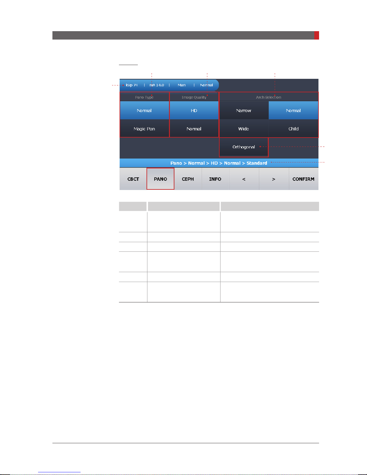
PANO
2 3
1
No. Function Description
4
5
6
1
2
3
4
5
6
Imaging parameter
settings information
_
Pano Type Normal, Magic Pan(Optional)
Image Quality HD, Normal
Arch Selection
Selects the type of patient’s dental
arch
Orthogonal Mode Minimizes overlapping in the image
Selection Settings
Displays the current selections in
sequential order.
37
PaX-i3D Green (PHT-60CFO) User Manual
3 PaX-i3D Green Imaging System Overview
NOTE
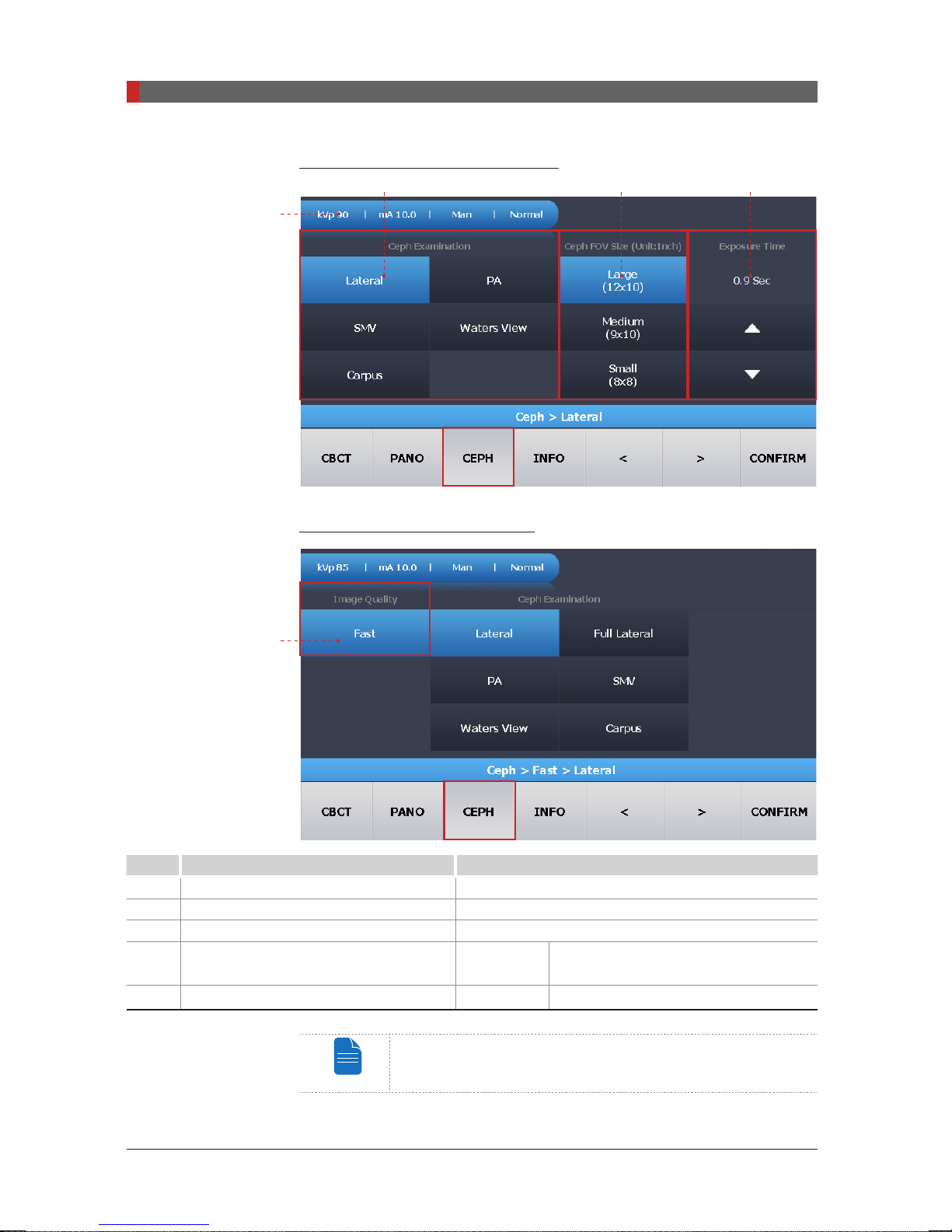
CEPH: OP Model (Oneshot type)
2 3 4
1
CEPH: SC Model (Scan Type)
5
No. Function Description
1
Imaging parameter settings information _
2
CEPH Examination _
3
CEPH FOV Size (inches) _
4
Exposure Time Adjustment
5
Image Quality Fast Fast Scan
Exposure time can be adjusted by resolution of 0.1 s in the
range of 0.5 s to 1.2 s (One shot type only).
Oneshot
type
Enable the user to adjust the exposure
time with the UP and DOWN buttons.
38

PaX-i3D Green (PHT-60CFO) User Manual
3.3.3 Emergency Stop Switch
During operation, the following emergency situations may occur:
■X-ray emission continues after the exposure switch has been released
3 PaX-i3D Green Imaging System Overview
■Injury to the patient or damage to the equipment
■Other emergency situations
If a problem occurs during image acquisition, press the red
Switch
equipment’s electrical components. To reset the
it clockwise until it pops up.
to immediately stop the moving parts and cut off all power to the
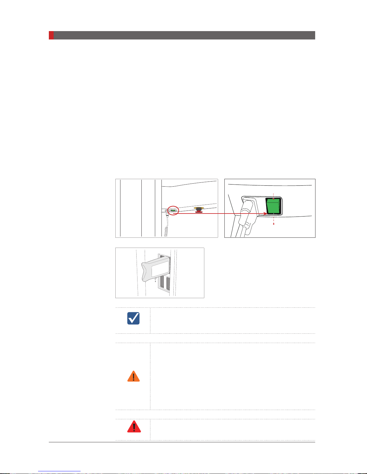
3.3.4 The Exposure Switch
Exposure Button
Exposure Indicator light
Green: Ready
Orange: X-ray On
Emergency Stop
Emergency Stop Switch
The exposure switch allows the operator
to control image acquisition from outside
of the X-ray room. Press and hold the
exposure switch down until acquisition
is complete. Premature release of
the exposure switch will abort image
acquisition.
Pressing the exposure switch activates the
orange indicator light to indicate that the
X-ray is being emitted.
, turn
39
PaX-i3D Green (PHT-60CFO) User Manual
3 PaX-i3D Green Imaging System Overview
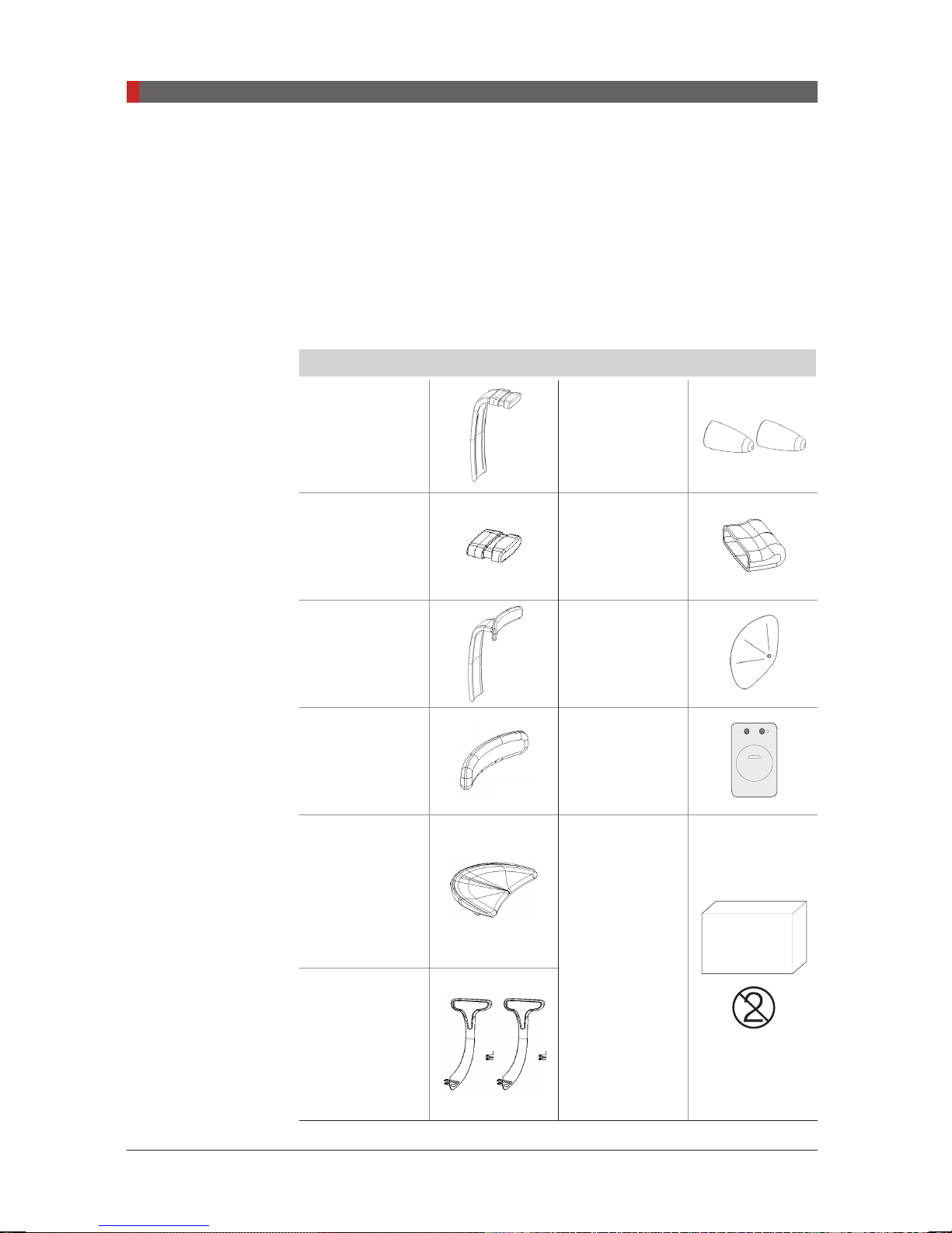
3.3.5 Components and Positioning Accessories
The following accessories can be disinfected after they have been separated
from the equipment.
Disinfect all accessories which come into direct contact with the patient, such
as the bite block, Chinrest or temple supports, using an alcohol-based solution
and allow them to dry before use.
Accessories
Bite block:
Normal
Silicon cover:
bite block
Chin Support:
TMJ, Sinus
Silicon cover:
Chin Support
Ear Rod cover
(1 set)
Silicon cover:
Nasal Positioner
Protractor:
CEPH
Carpus plate
Supports (1 set)
40
Silicon cover:
Chinrest
Temple
Hygiene cover :
Panorama Cover
300 pcs
bite block
(single use)

PaX-i3D Green (PHT-60CFO) User Manual
3 PaX-i3D Green Imaging System Overview
0434
3.4
Marks and Symbols
Symbols Description Location
Alternate current Attention:
consult accompanying documents
Dangerous voltage Power board
Protective earth (Ground) Power board
Off
(power: disconnect from the main switch)
On (power: connect to the main switch) Main switch
TYPE B Equipment Label
Radiation hazard Label
EC representative Label
Label
Main switch
The CE symbol indicates that this product
complies with the European Directive for
Medical Devices 93/42/EEC as amended by
2007/47/EC as a class IIb device.
UL mark: UL 60601-1 / CAN/CSA
C22.2 No.601.1 3ZY1
Address where the equipment was
manufactured
This symbol indicates that electrical and
electronic equipment must not be disposed
of as unsorted municipal waste and must be
collected separately.
This symbol warns ESD hazard.
This symbol indicates that this equipment is
classied as a CLASS 1 LASER PRODUCT in
accordance with IEC 60825-1 ED.1 regulations.
Date of manufacture Label
Refer to Instruction manual Label
Label
Label
Label
Label
MCU board/
Board package
Label
41

This page is left intentionally blank.

4
Software Overview
4.1
4.2
4.3
4.3.1 PANO .................................................................................... 50
4.3.2 CEPH ...................................................................................55
4.3.3 CBCT ...................................................................................57
PC System Requirements (Recommended) ....................... 44
EasyDent / EzDent-i ............................................................ 45
Imaging Software Overview ................................................. 46

PaX-i3D Green (PHT-60CFO) User Manual
4 Software Overview
NOTE
4 Software Overview
Three programs come with this equipment to acquire, process, and view the
image:
■
EasyDent / EzDent-i
■
Ez3D plus / Ez3D-i
: 2D viewer, analysis, and patient management
: 3D Viewer and analysis
■Imaging software:
4.1
Item HP LENOVO
CPU
RAM
Hard disk drive
Graphic board
Ethernet interface
Serial Port (RS232)
Power supply
PC System Requirements (Recommended)
Intel Xeon E5-1607v3 3.1GHz 1866 4C Intel Xeon E5-1607v3 3.1GHz 1866 4C
8GB DDR4-2133 Registered RAM
or larger
1TB SATA 7200 RPM 1st HDD 1TB SATA 7200 RPM 1st HDD
NVIDIA Quadro K2200 4GB NVIDIA Quadro K2200 4GB
Integrated Intel I218LM PCIe GbE Integrated Intel I217LM PCIe GbE
HP Serial Port Adapter Kit (Option) 1 (On Board)
≥ 700 Watts (90 % Efficiency) ≥ 650 Watts (85 % Efficiency)
PANO / CEPH / CBCT
- Image quality may be diminished if the PC specications
are not met, please adhere to the requirements specied
in the following table.
- DO NOT place the PC or peripheral equipment connected
to the PC in the immediate vicinity of the patient
8GB DDR4-2133 or larger
Slots
CD/DVD drive
Monitor
Operating system
Recommended system
44
2 PCI Express Gen3 x 16 slots
1 PCI Express Gen3 x 8 slot
1 PCI Express Gen2 x 4 slot
1 PCI Express Gen2 x 1 slot
1 PCI slot 1 PCI slot
DVD-ROM, DVD+/-RW, Blu-Ray DVD-ROM, DVD+/-RW, Blu-Ray
19”1280 x 1024 screen resolution 19”1280 x 1024 screen resolution
Windows 7 Professional 64-Bit Windows 7 Professional 64-Bit
Z440 P500
2 PCI Express Gen3 x 16 slots
1 PCI Express Gen3 x 4 slot
1 PCI Express Gen2 x 4 slot
1 PCI Express Gen2 x 1 slot

PaX-i3D Green (PHT-60CFO) User Manual
4 Software Overview
NOTE
4.2
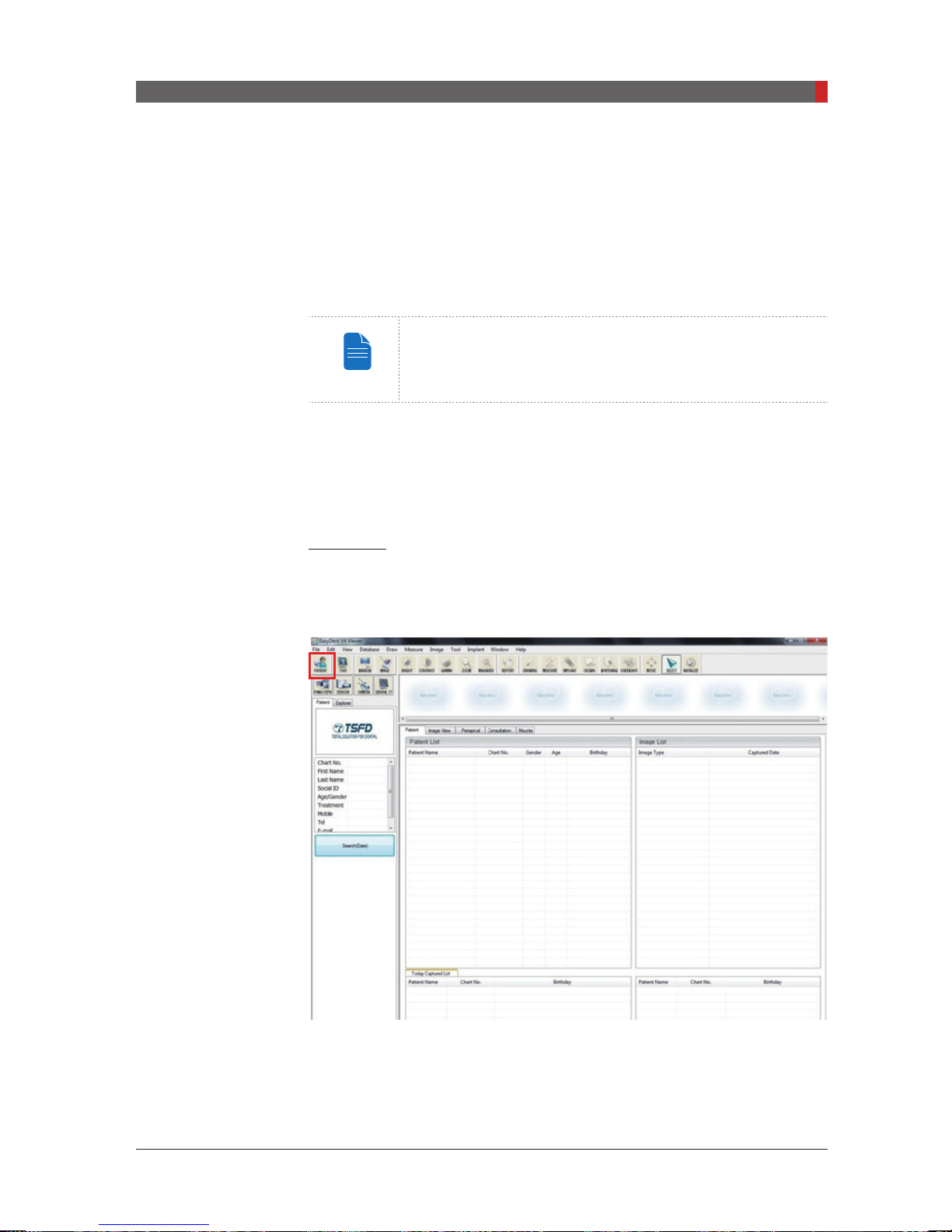
EasyDent / EzDent-i
As the basic imaging platform for all VATECH dental X-ray equipment,
EasyDent / EzDent-i
interfaced with
are imported directly into
can be performed quickly and easily.
The screenshot below is of
is designed to be easy to use. The Imaging Program is
EasyDent / EzDent-i.
EasyDent / EzDent-i
EasyDent / EzDent-i’s
For more details about patient search, refer to sections
“5.2.1 Creating a New Patient Record” and “5.2.2 Retrieving
Patient Records”.
Images acquired by the Imaging Program
, where analysis and diagnosis
initial GUI window.
45

PaX-i3D Green (PHT-60CFO) User Manual
4 Software Overview
NOTE
NOTE
4.3
Imaging Software Overview
Imaging parameters can be set using the imaging program. The following
screenshot shows the main interface in PANO mode. For details concerning
PANO, CEPH and CBCT imaging, refer to sections
A
B
You can set the imaging parameters on either the touch
screen or the imaging program running on the PC. They are
synched in real time and display the same environmental
settings. For more details on the Touch Screen, refer to
“3.3.2 Touch Screen”.
4.3.1 - 4.3.3.
I K
J
L
M
N
C
D
E
F
A. Imaging Mode Display
This displays the current imaging mode.
:
- Indicates that the Magic PAN is supported in the PANO
imaging modality.
- Is displayed only for the Standard mode, with the Magic
PAN enabled.
G H
P
O
46

PaX-i3D Green (PHT-60CFO) User Manual
4 Software Overview
NOTE
NOTE
B. Scanning Status and Image Preview Window
This shows image acquisition progression in real- time.
C. Patient Information
This displays information about the selected patient.
D. Imaging Guide Window
This displays various text instructions for the operator to follow.
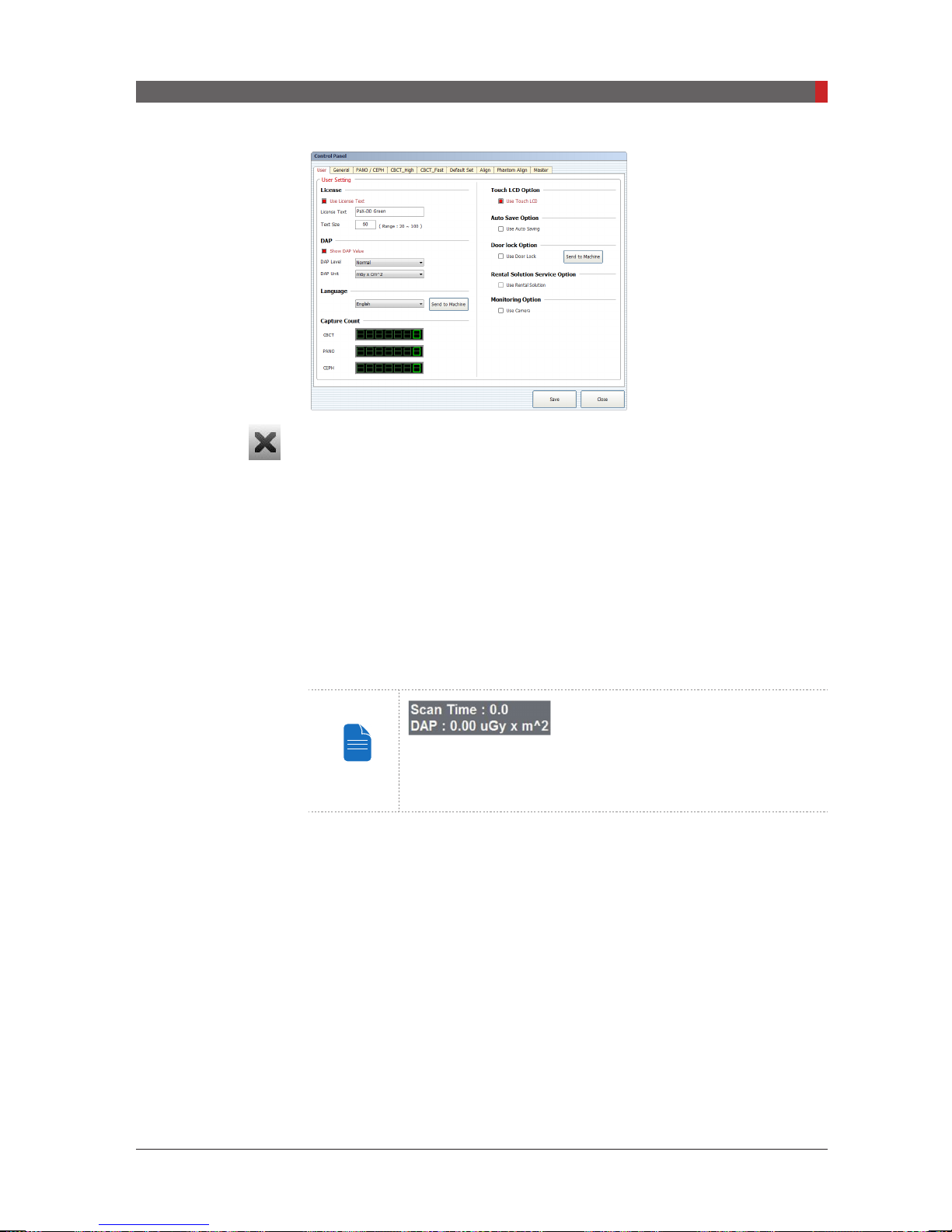
E. Scan Time and DAP Display Window
Upon clicking
Conrm
, the scan time and estimated DAP value is displayed in
this window.
F. Tube Voltage and Current Adjustment
If the patient is selected in EasyDent / EzDent-i, the default kVp/mA according
to the patient’s information (gender/age) is displayed. This tool adjusts the kVp
and mA values or control the power of the X-ray in order to improve image
quality. If necessary, adjust the kVp and mA values manually using the arrows.
For the tube voltage and its correspondence with the
current patient, refer to “Appendix 1. Recommended X-ray
Exposure Table”.
G. Patient Gender
This displays the current patient’s gender as entered in EasyDent / EzDent-i’s
patient information. If necessary, gender can be manually selected.
Age Group / Gender VATECH’s Standard
Adult
Child
Man
Woman
≤12
≥13
H. X-ray intensity
This tool selects X-ray intensity.
Depending on the circumference of the patient’s head,
X-ray intensity may be classied as Hard, Normal, or Soft :
Soft ≤ Normal ≤ Hard
Age
Group
Child
Average head
circumference
53±3 cm
Range
(cm)
classication of head
circumference
> 53±3 Hard
53±3 Normal
53±3 < Soft
> 56±3 Hard
Adult
56±3 cm
56±3 Normal
56±3 < Soft
47
PaX-i3D Green (PHT-60CFO) User Manual
4 Software Overview
NOTE
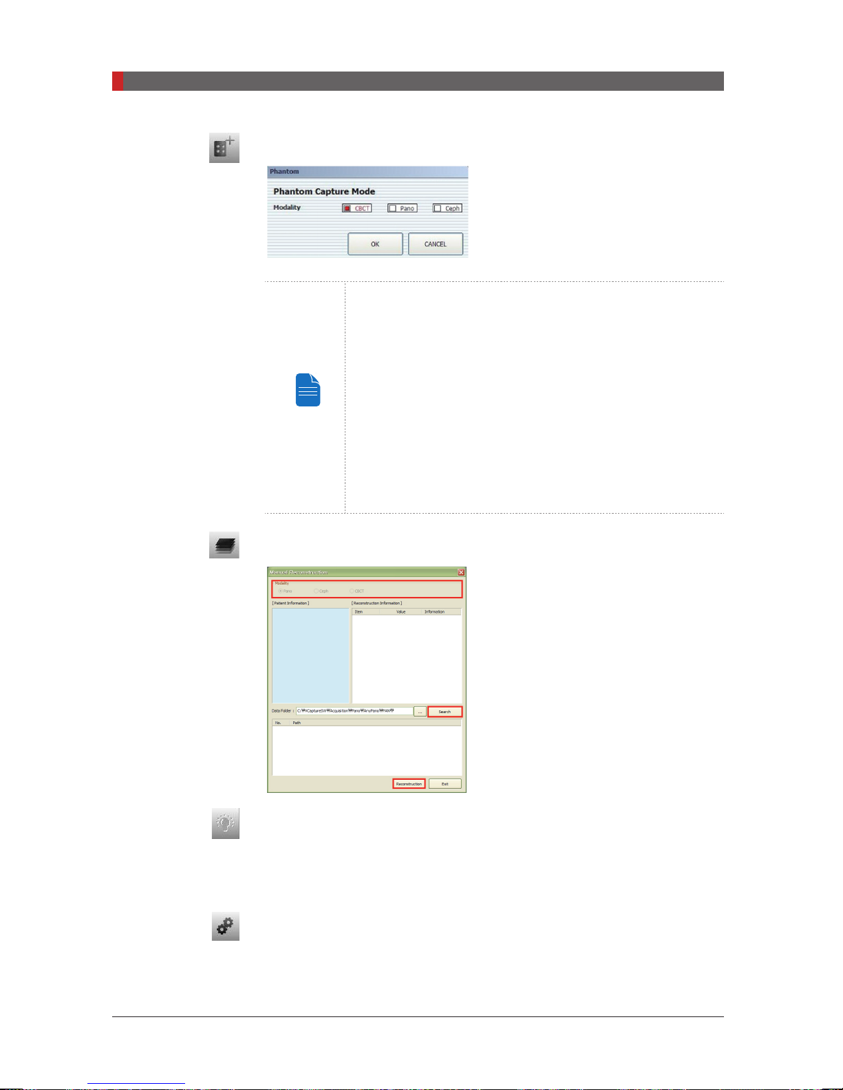
I. Phantom Capture
Image acquisition using the Phantom Jig:
1. Click Phantom Capture Icon.
2. Select the Modality, followed by OK.
3. Check the parameters displayed in the main GUI
window. If correct, click the ‘Conrm’ button.
4. Align the Phantom Jig, and click the ‘Ready’ button.
This function is used when the Phantom
Jig is being used to acquire images.
5. Press and hold down the exposure switch.
J. Manual Image Reconstruction
If automatic reconstruction of the image
fails, use this function to reconstruct the
image manually. Select
Modality
and click
Search → Reconstruction.
K. Laser Beam On / Off Button
Use this icon to turn the laser beam on or off for patient positioning. This
button is enabled when the
CONFIRM
button is clicked after the imaging
environmental parameters are configured.
L. Settings
This Control Panel displays and sets various equipment-related parameters,
including language, automatic save, DAP display unit, etc.
48
PaX-i3D Green (PHT-60CFO) User Manual
M. Exit
NOTE
This button exits the capturing program.
N. Imaging Mode
4 Software Overview
This selects an imaging mode – PANO, CEPH or CBCT. Refer to section
~ 4.3.3
for the details regarding
PANO, CEPH and CBCT
imaging modes.
4.3.1
O. Conrm
After conrming all settings required for scanning, press
CONFIRM
to apply the
settings.
When you click CONFIRM, the scan time and estimated
DAP (Dose Area Product) value will be shown on the main
display for the exposure you are going to take.
P. Ready
This button is used when all aspects of preparation have done for image
acquisition (including parameter settings and patient positioning)
49
PaX-i3D Green (PHT-60CFO) User Manual
4 Software Overview
NOTE
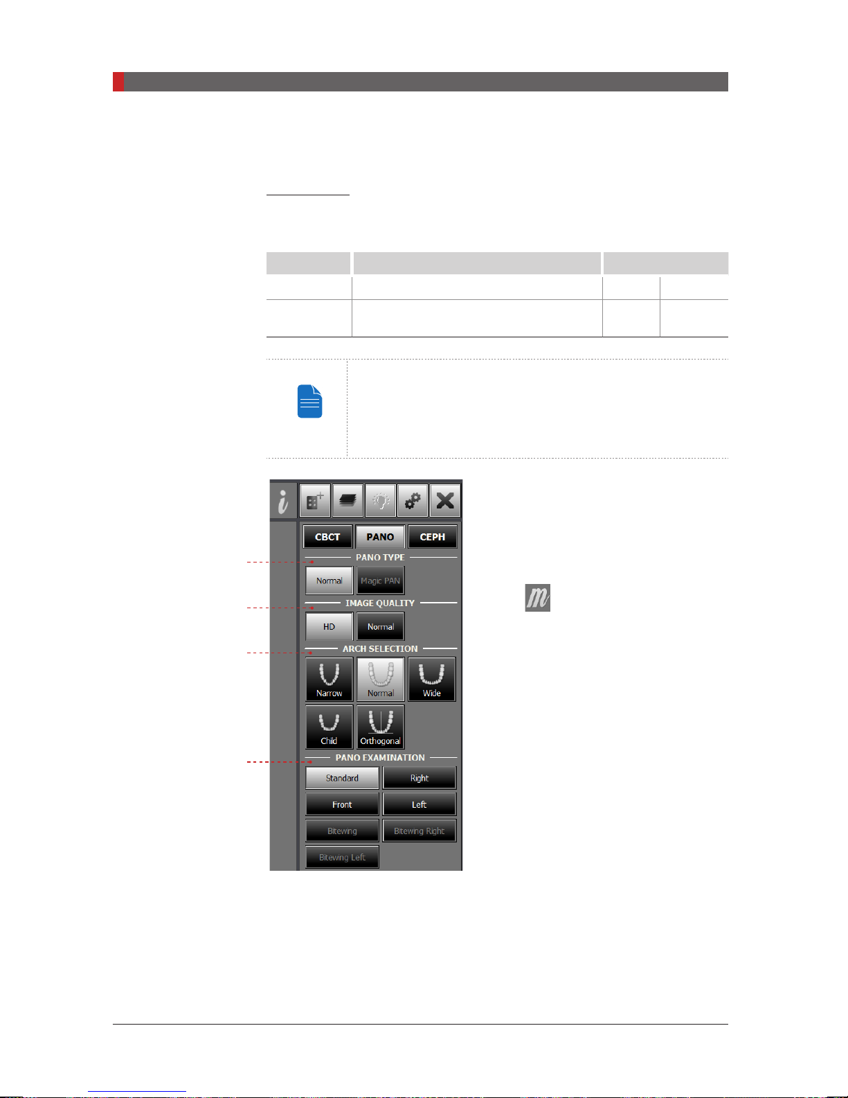
4.3.1 PANO
PANO Type
The PaX-i3D Green conditionally offers 2 levels of panoramic imaging system.
Level Mode Option
Normal Pano examination / Special examination - -
Magic PAN Pano examination (
Standard
Magic PAN: an high quality image reconstructed from the
optimal auto-focused images throughout the panoramic
region to correct the improper patient positioning and
rotating unit’s trajectory.
mode)
Magic
PAN
optional
A. PANO Type:
PAN or Normal) can be selected for PANO
imaging.
A
B
C
D
Magic PAN (optional)
the sharper image. When enabled, the
symbol
the imaging modes which incorporate this
feature.
One of two modes (Magic
: a feature to acquire
appears on the upper right for
B. Image Quality
One of two modes (HD or Normal) can be selected for PANO imaging.
■
■
50
HD
: Image with higher resolution than
Normal
: Normal image
Normal
Mode
PaX-i3D Green (PHT-60CFO) User Manual
4 Software Overview
NOTE
CAUTION
Setting the default mode in the PANO: The most frequently
used mode among the HD and Normal can be congured
as the default, which requires the authority.
To change the default mode,
1. Ask the engineer in your region for the mode change.
2. Re-run the imaging program after setting up the related
parameters.
The default mode, if any, specified in a specific country
can't be changed for the user's intent.
C. Arch Selection
Select the patient’s arch type: Narrow, Normal, Wide, Child, and Orthogonal.
Orthogonal:
Enables the image to be acquired with overlapping regions of the
teeth minimized.
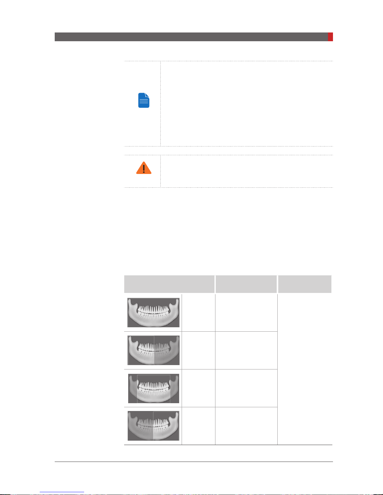
D. PANO Examination
Acquire the image for a specic ROI in panoramic mode.
Mode
Standard
Region of Interest:
PANO Image
Imaging standard
images
Right Imaging lateral right
Front Imaging frontal area
Remark
Supported by
any arch type
selection
Left Imaging lateral left
51
PaX-i3D Green (PHT-60CFO) User Manual
4 Software Overview
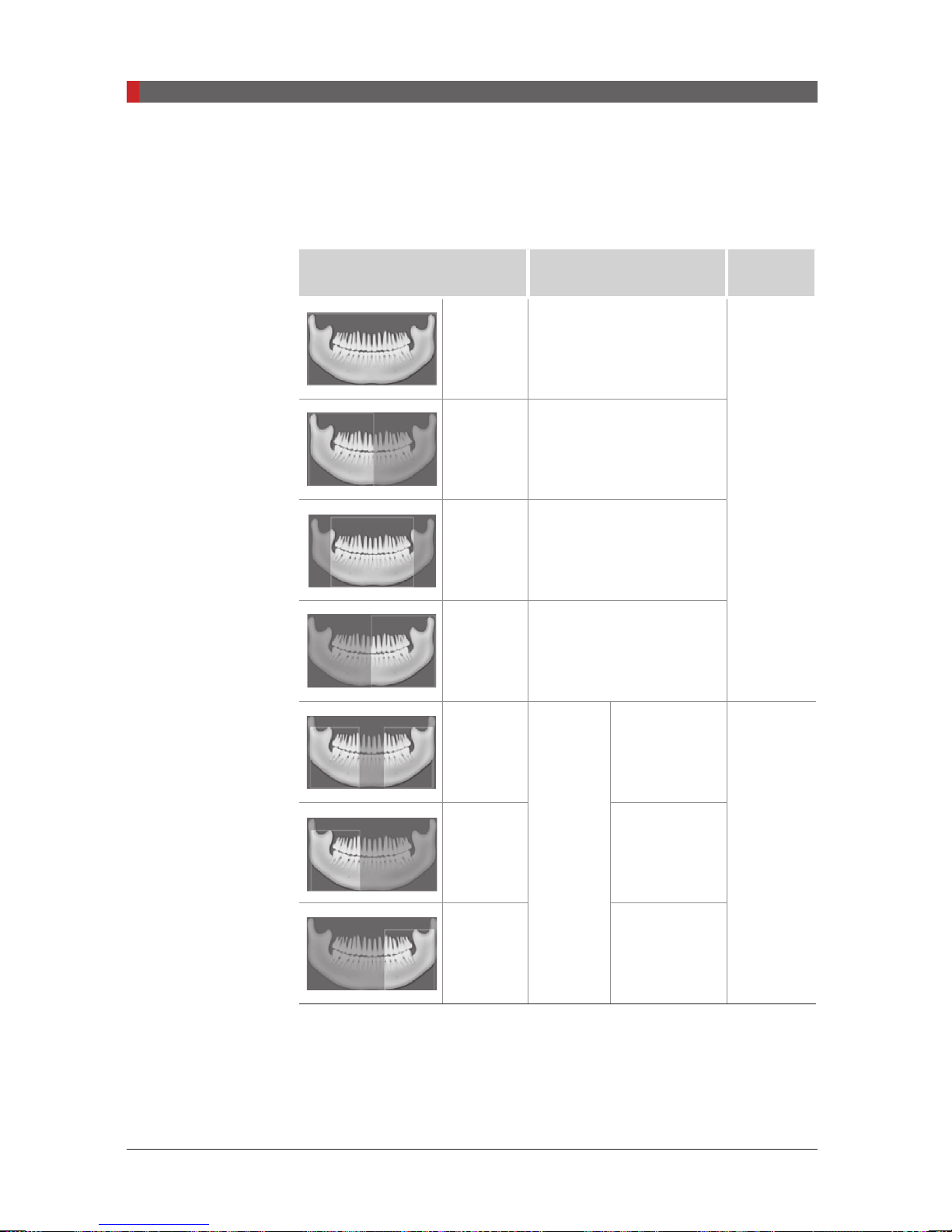
The following table summarizes the sub-modes for orthogonal imaging.
*Orthogonal mode
teeth.
Sub-mode
: Acquires an image that minimizes overlapping regions of
Standard
Region of Interest:
Orthogonal
Imaging PANO Standard
image
Remark
Right Imaging PANO lateral right
Supported
by any
arch type
selection
Front Imaging PANO frontal area
Left Imaging PANO lateral left
Bitewing
Bitewing
Right
Bitewing
Left
Bitewing
imaging
Left/Right
Right region
Left region
Supported
by any
arch type
selection
52
PaX-i3D Green (PHT-60CFO) User Manual
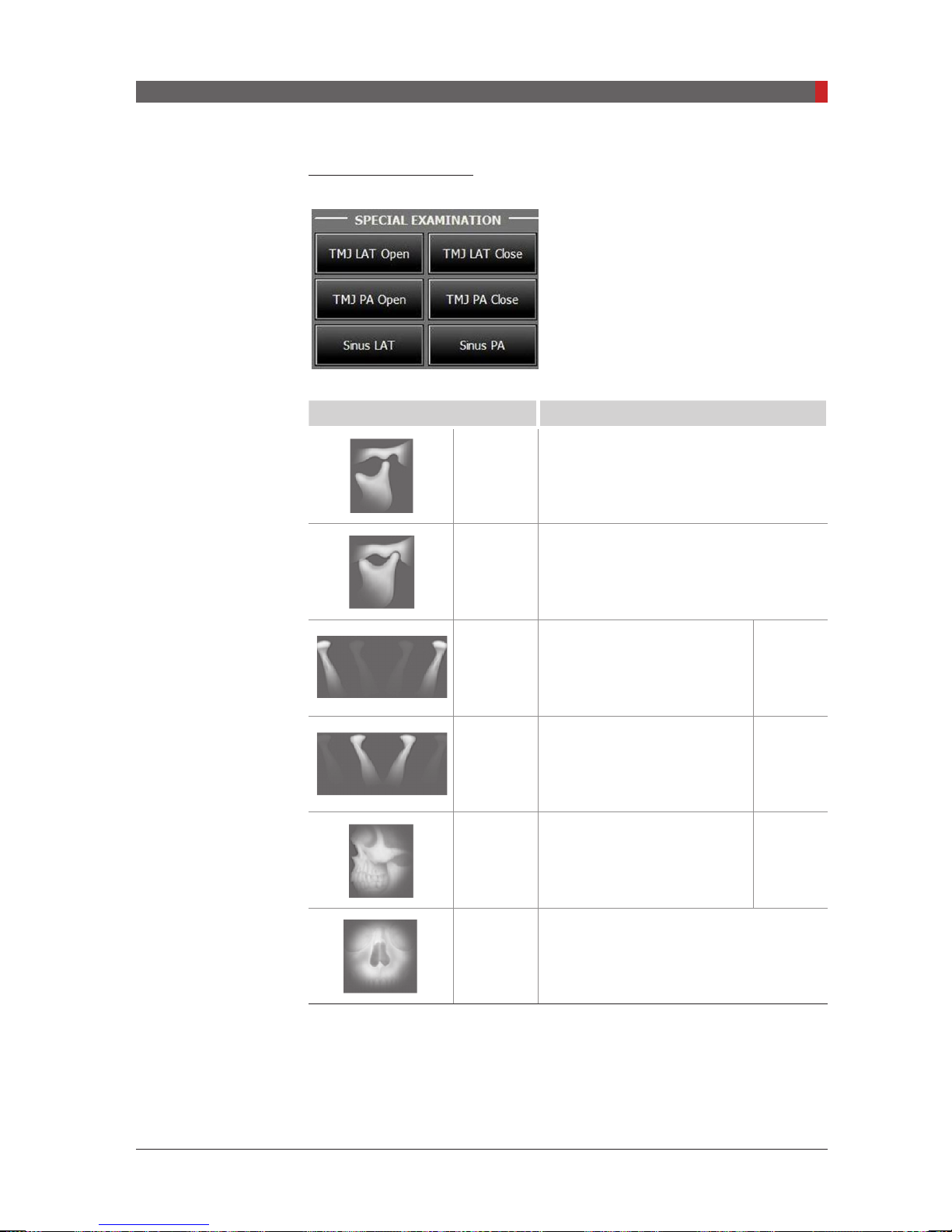
Special Examination
Mode Details
4 Software Overview
TMJ LAT
Open
TMJ LAT
Close
TMJ PA
Open
TMJ PA
Close
Sinus LAT
Takes a side view image of the TMJ with
the mouth open.
Takes a side view image of the TMJ with
the mouth closed.
Takes a posterior/anterior
image of the TMJ with the
optional
mouth open.
Takes a posterior/anterior
image of the TMJ with the
optional
mouth closed.
Takes a side view image of
the sinus.
optional
Sinus PA
Takes a posterior-anterior image of the
sinus.
53
PaX-i3D Green (PHT-60CFO) User Manual
4 Software Overview
NOTE
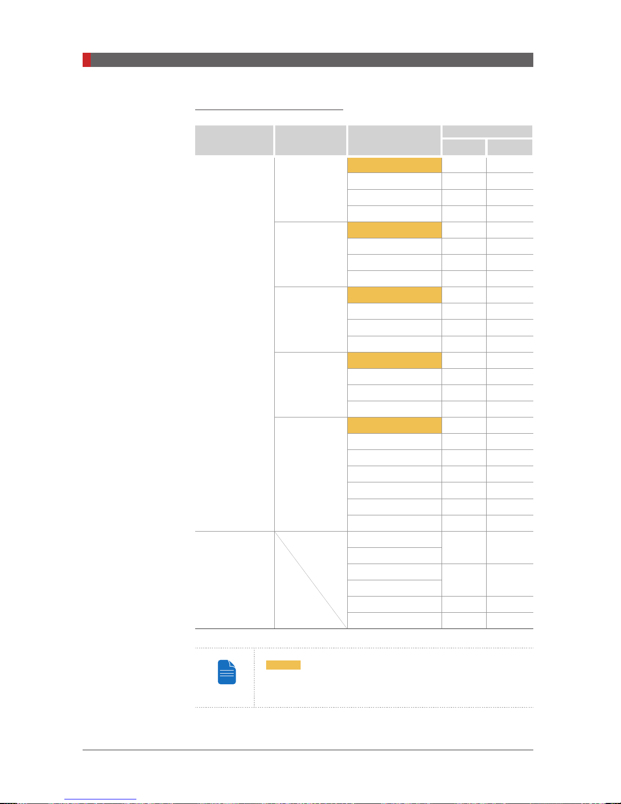
Exposure Time (Max. 20.2 s)
Examination Arch Selection Examination Mode
Standard 13.5 10.1
Front 11.1 8.4
Narrow
Right 6.7 5.1
Left 6.7 5.1
Standard 13.5 10.1
Front 11.1 8.4
Normal
Right 6.7 5.1
Left 6.7 5.1
Standard 13.5 10.1
Front 11.1 8.4
Wide
Right 6.7 5.1
PANO
Examination
Left 6.7 5.1
Standard 11.5 8.6
Front 9.2 6.9
Child
Right 5.7 4.3
Left 5.7 4.3
Standard 13.5 10.1
Front 11.1 8.4
Right 6.7 5.1
Orthogonal
Left 6.7 5.1
Bitewing 9.6 7.2
Bitewing Right 4.8 3.6
Bitewing Left 4.8 3.6
TMJ LAT Open
TMJ LAT Close
Special
Examination
TMJ PA Open
TMJ PA Close
Sinus LAT 6.0 4.5
Sinus PA 10.3 7.7
Scan Time (s)
HD Normal
6.1 4.6
7.0 5.3
54
-
: Indicates that the examination supports Magic PAN.
- Maximum exposure time deviation: ± 10 % (IEC 60601-2-7)

PaX-i3D Green (PHT-60CFO) User Manual
4.3.2 CEPH
Depending on the sensor type employed, one of the three kinds of imaging
program comes with the equipment for the CEPH mode examination.
A
B
4 Software Overview
A. Image Quality
Xmaru2301CF sensor
(scan type)
B
C
D
1210SGA sensor
(one shot type)
55
PaX-i3D Green (PHT-60CFO) User Manual
4 Software Overview
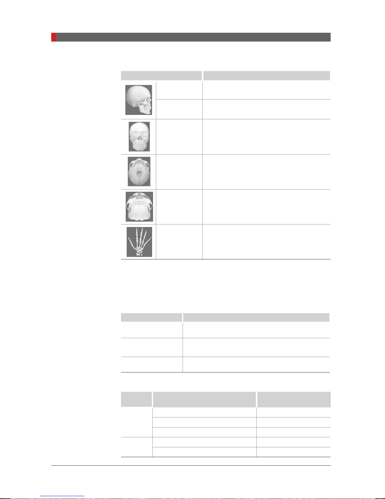
B. CEPH Examination
Mode Details
Lateral Takes a lateral view image partially
Full Lateral
(Scan CEPH)
Takes a lateral view image fully
PA Takes a posterior-anterior image
SMV Takes a SMV(Sub-Mento Vertical) image
Waters View Takes a Waters View image
CARPUS Takes a CARPUS image
C. FOV Selection
The Multi FOV is supported for the equipment with the OS (one shot) CEPH
sensor (optional).
56
[With one shot type sensor]
FOV Details
12 x 10 (inches)
30.48 x 25.40 (cm)
9 x 10 (inches)
22.86 x 25.40 (cm)
8 x 8 (inches)
20.32 x 20.32 (cm)
Full size
Region of the no interest of the rear part of the head
is eliminated to minimize the X-ray exposure area.
Child
D. Exposure Time
Sensor
Type
Examination Modes Scan Time (s) - Default
Full Lateral 5.4
Scan
PA / SMV / Waters View / Carpus 4.9
Oneshot
PA / SMV / Waters View / Carpus 0.9
Lateral 4.0
Lateral 0.7
PaX-i3D Green (PHT-60CFO) User Manual
NOTE
4.3.3 CBCT
NOTE
1
2
3
4 Software Overview
Exposure time can be adjusted by resolution of 0.1 s in the
range of 0.5 s to 1.2 s (One shot type only).
4
5
6
Max FOV 160 x 100
Xmaru1524CF MP
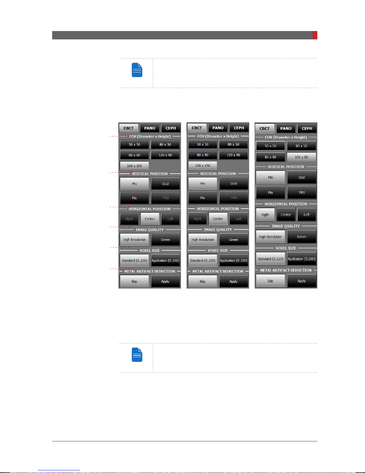
A. FOV Size
This selects the FOV (Field Of View) size.
The FOV size is decided by the attached CT sensor
(optional).
B. Vertical Position
This selects the vertical imaging region:
TMJ.
1
Max FOV 150 x 150
Xmaru1524CF MP
Mandible, Occlusion, Maxillary or
Max FOV 100 x 80
Xmaru1215CF MP
57

PaX-i3D Green (PHT-60CFO) User Manual
4 Software Overview
C. Horizontal Position
This selects the horizontal imaging region:
Guidance Image FOV (mm) ROI
160 X 100 Mn - Center
150 X 150 Mn - Center
120 X 90 Mn - Center
100 X 80 Mn - Center
Right, Center, or Left.
58
80 X 80 Mn - Center
80 X 50 Mn - Center
50 X 50
4. Image Quality
Model Mode Scan Time
MaX FOV 100 x 80 High Resolution/Green
MaX FOV 160 x 100 High Resolution/Green
MaX FOV 150 x 150 High Resolution/Green
Mn / Left Central
Incisor
9.0/5.9 s
9.0/5.9 s
15.0/9.0 s

PaX-i3D Green (PHT-60CFO) User Manual
E. Voxel Size
NOTE
CAUTION
FOV (mm) Mode Voxel Size (mm)
50 x 50
80 x 50
80 x 80
100 x 80
120 x 90
150 x 150
160 x 100
4 Software Overview
Standard 0.08
Application 0.12
Standard 0.12
Application 0.20
Standard 0.12
Application 0.20
Standard 0.12
Application 0.20
Standard 0.20
Application 0.30
Standard 0.20
Application 0.30
Standard 0.20
Application 0.30
F. Metal Artifact Reduction
This function is used to reduce the articial effect generated by patients with
metallic materials in their dental region and improve image quality. When Metal
Artifact Reduction is selected, the time required to reconstruct an image is
doubled.
Setting the default mode in the CBCT: The most frequently
used mode under the Image Quality, Voxel Size, Metal
Artifact Reduction can be congured as the default, which
requires the authority to change.
To change the default mode,
1. Ask the engineer in your region for the mode change.
2. Re-run the imaging program after setting up the related
parameters.
The default mode, if any, specified in a specific country
can't be changed for the user's intent.
59

PaX-i3D Green (PHT-60CFO) User Manual
4 Software Overview
FOV & Examination Positioning
FOV Size (mm) Vertical Position
Mx. O
50 X 50
80 X 50
80 X 80
100 x 80
120 X 90
150 X 150
160 X 100
Occl. X
Mn. O
TMJ X
Mx. O O O
Occl. O O O
Mn. O O O
TMJ O O O
Mx. X O X
Occl. X O X
Mn. X O X
TMJ X X X
Mx. X O X
Occl. X O X
Mn. X O X
TMJ X X X
Mx. X O X
Occl. X O X
Mn. X O X
TMJ X X X
Horizontal Position
Right Center Left
A specic tooth selectable
60
Image Reconstruction Time
Xmaru1215CF Master Plus
Reconstruction Time (s)
High Resolution Mode
(Scan Time: 9.0 s)
MAR
Skip
0.08 48 102 41 84 482
0.12 24 53 21 41 137
0.12 39 100 33 77 358
0.20 19 47 15 36 77
0.12 63 145 53 118 579
0.20 30 63 24 49 122
0.12 87 206 74 167 922
0.20 32 74 26 56 191
FOV (mm)
50 x 50
80 x 50
80 x 80
100 x 80
Voxel
Size
Green Mode
(Scan Time: 5.9 s)
MAR
Apply
MAR
Skip
MAR
Apply
File Size
(MB)

PaX-i3D Green (PHT-60CFO) User Manual
Xmaru1524CF Master Plus (Max FOV 160 x 100)
NOTE
Reconstruction Time (s)
4 Software Overview
FOV
(mm)
Voxel
Size
High Resolution Mode
(Scan Time: 9.0 s)
MAR
Skip
MAR
Apply
Green Mode
(Scan Time: 5.9 s)
MAR
Skip
MAR
Apply
File Size
(MB)
0.08 48 102 41 84 482
50 x 50
0.12 24 53 21 41 137
0.12 39 100 33 77 358
80 x 50
0.20 19 47 15 36 77
0.12 63 145 53 118 579
80 x 80
0.20 30 63 24 49 122
0.20 47 120 40 92 313
120 x 90
0.30 30 74 24 54 92
0.20 91 212 70 165 622
160 x 100
0.30 48 128 35 86 184
The test condition:
- PC system: HP Z440, Windows7 pro 64bit OS: Intel® Xeon® E5-1607v3 4C
3.1GHz 1866 10MB cache CPU, 8GB RAM, NVIDIA Quadro K2.200 4GB
VGA Card.
- Object: Skull
- Image reconstruction time varies depending on computer
specications and/or working conditions.
- The Xmaru series stand for the individual sensor.
- MAR: Metal Artifact Reduction
61

PaX-i3D Green (PHT-60CFO) User Manual
4 Software Overview
NOTE
Xmaru1524CF Master Plus (Max FOV 150 x 150)
Reconstruction Time (s)
FOV
(mm)
Voxel
Size
High Resolution Mode
(Scan Time: 9.0 s)
MAR
Skip
MAR
Apply
Green Mode
(Scan Time: 5.9 s)
MAR
Skip
MAR
Apply
File Size
(MB)
0.08 54 114 45 90 482
50 x 50
0.12 19 45 16 35 137
0.12 43 98 35 76 358
80 x 50
0.20 17 44 13 32 77
0.12 68 153 57 120 579
80 x 80
0.20 25 60 19 44 122
0.20 45 107 35 80 313
120 x 90
0.30 27 68 19 46 92
0.20 98 173 84 135 812
150 x 150
0.30 43 105 33 73 239
The test condition:
- PC system: HP Z440, Windows7 pro 64bit OS: Intel® Xeon® E5-1607v3 4C
3.1GHz 1866 10MB cache CPU, 8GB RAM, NVIDIA Quadro K2200 4GB VGA
Card.
62
- Object: Skull
- Image reconstruction time varies depending on computer
specications and/or working conditions.
- The Xmaru series stand for the individual sensor.
- MAR: Metal Artifact Reduction

5
Getting Started
5
5.1
5.2
5.2.1 Creating a New Patient Record ............................................65
5.2.2 Retrieving Patient Records ...................................................67
5.3
Getting Started .................................................................... 64
Turning on the PaX-i3D Green ............................................ 64
Running the Image Viewer .................................................. 65
Initiating the Imaging Program ............................................. 69
PaX-i3D Green (PHT-60CFO) User Manual
5 Getting Started
WA
G
CAUTION
5 Getting Started
5.1
Turning on the PaX-i3D Green
To turn on the system, follow the steps below:
A. Before turning the equipment on, check whether the system is correctly
connected and installed (check the connection status between the equipment
and the PC).
B. Turn the
ON / OFF
switch underneath the handle frame to the ON position.
OFF (O)
ON (I)
C. Insert the license key for
into the USB port on the back of PC.
The license key for
be attached to view or analyze the 3D
images.
Ez3D plus
Ez3D plus
must
64
IMPORTANT
CAUTION
RNIN
- If it has not been used for a long time, allow at least an hour
before the rst exposure since turning on the equipment.
- Condensation could form inside the equipment if it is a
different temperature than the surrounding room. Only turn
on the equipment once it has reached room temperature.
- Wait at least 20 seconds after the equipment has been
turned off to turn it back on.
- Allow the equipment to warm up for at least 5 minutes
before acquiring images or preferably more than 30
minutes for image quality.
Do not position the patient in the unit while it is initiating.
The patient could be injured if the equipment malfunctions.
PaX-i3D Green (PHT-60CFO) User Manual
5 Getting Started
NOTE
5.2
Running the Image Viewer
EasyDent / EzDent-i
equipments. The Imaging Program is interfaced with
your desktop, double-click
main window will be displayed.
is a basic imaging platform for all VATECH’s dental X-ray
EasyDent / EzDent-i
For further details on this subject, refer to the EasyDent /
EzDent-i user manual.
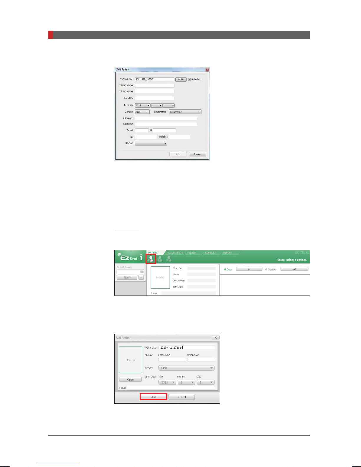
5.2.1 Creating a New Patient Record
To create a new patient record, follow the procedure outline below:
EasyDent
A. Click the
window.
Patient
icon on the upper left corner of the EasyDent’s main GUI
EasyDent / EzDent-i.
icon. The
EasyDent / EzDent-i
On
65
PaX-i3D Green (PHT-60CFO) User Manual
5 Getting Started
B. The following dialog box will open.
C. Enter the required patient information.
Name
are required elds which must be lled in. All other elds are optional,
Chart Number, First Name
but it is recommended that they be lled in.
D. Click
Add
to save the patient record.
EzDent-i
A. Click the
B. Enter the required patient information. The
First Name, and Last Name
chart number lls in automatically.)
Add Patient
icon from main GUI window.
Chart Number, E-Mail address,
are required elds which must be lled in. (The
, and
Last
C. Click
66
Add
to save the patient record.
PaX-i3D Green (PHT-60CFO) User Manual
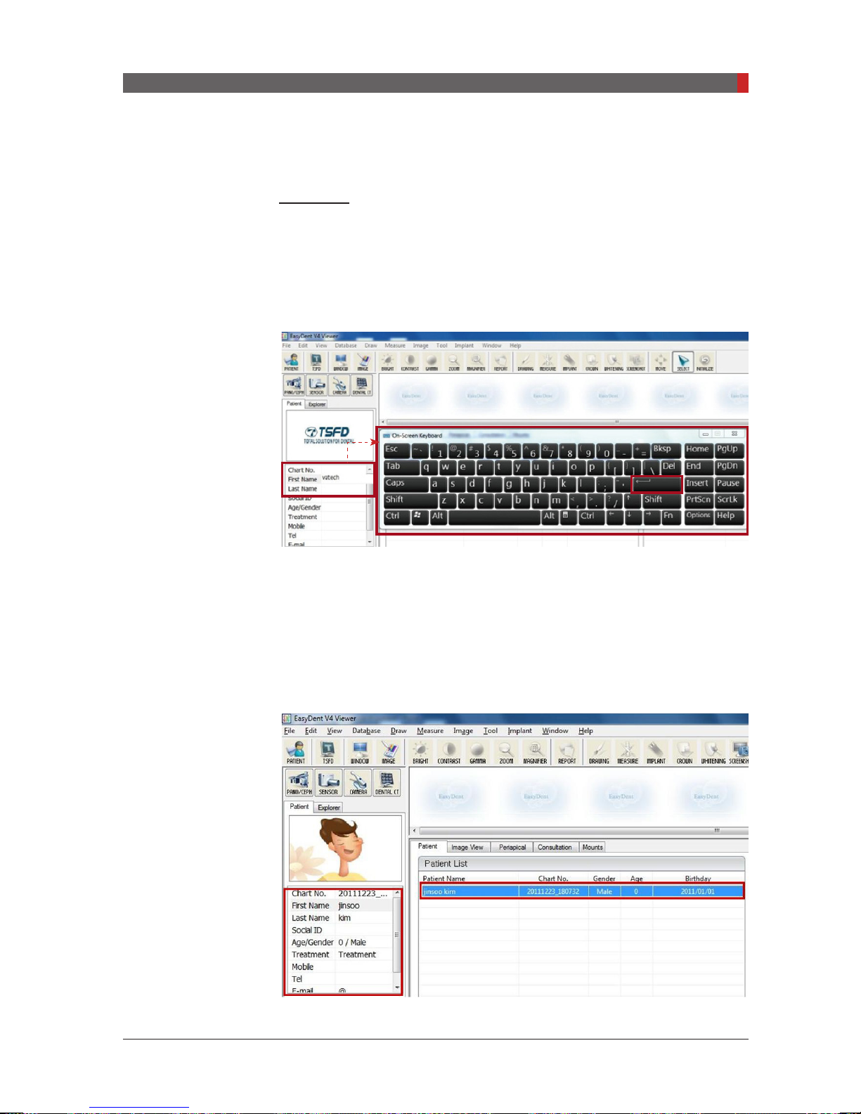
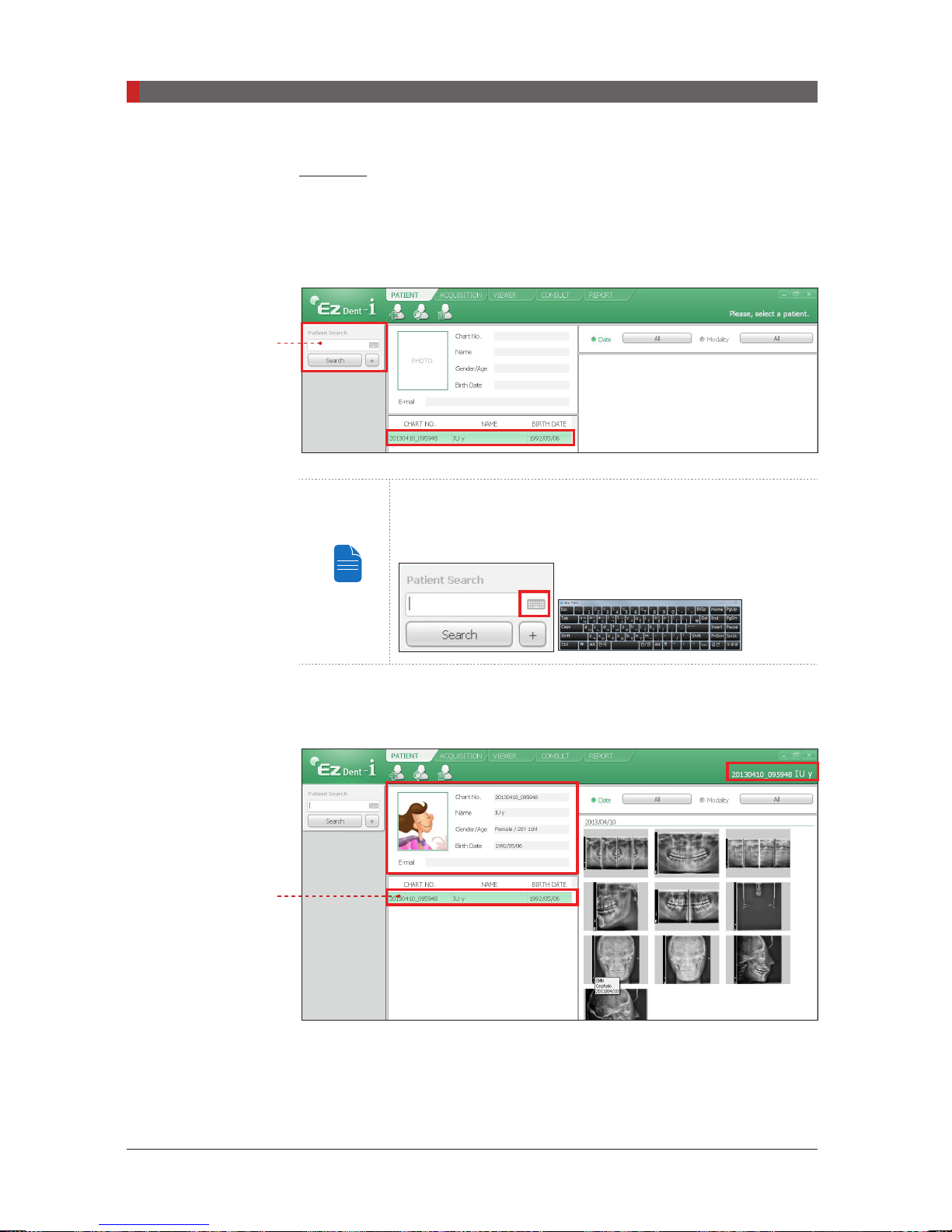
5.2.2 Retrieving Patient Records
EasyDent
You can search through the patient database using a patient’s chart number,
their rst name, or their last name.
5 Getting Started
A. On the
or Last name
Double click
B. Enter
mouse on the virtual key board and click the
be used to do the same job).
C. Patient information can be displayed on the
Patient List
Patient information pane
of the patient and the virtual keyboard will pop up.
the Chart No., First name, or Last name
.
, double-click the
Enter
Chart No., First name,
of the patient by clicking the
(The physical keyboard can
Patient information pane
and
67
PaX-i3D Green (PHT-60CFO) User Manual
5 Getting Started
NOTE
EzDent-i
Enter
A. Enter the name or chart number of the patient to be searched on the
pane and then click the
Search
button. The information on the patient that ts
the search condition appears.
Double-click the Keyboard icon to display the virtual
keyboard. You may search patient information using the
virtual keyboard.
Search
Double click
B. Double-click the patient information to see more details about the patient as
shown below.
68
PaX-i3D Green (PHT-60CFO) User Manual
5 Getting Started
NOTE
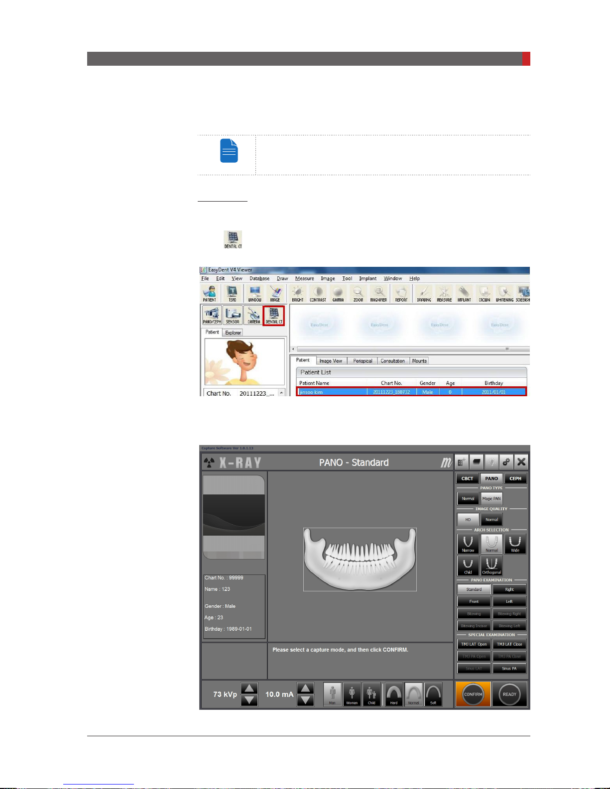
5.3
Initiating the Imaging Program
For a new patient, rst register the patient information.
EasyDent
A. First, click the patient information in the patient list, and click the
icon (
imaging program.
Dental CT
) in the upper left corner of the EasyDent’s main window to open the
B. The following imaging program window opens. The sole purpose of this
window is to control equipment settings and acquire images.
69
PaX-i3D Green (PHT-60CFO) User Manual
5 Getting Started
NOTE
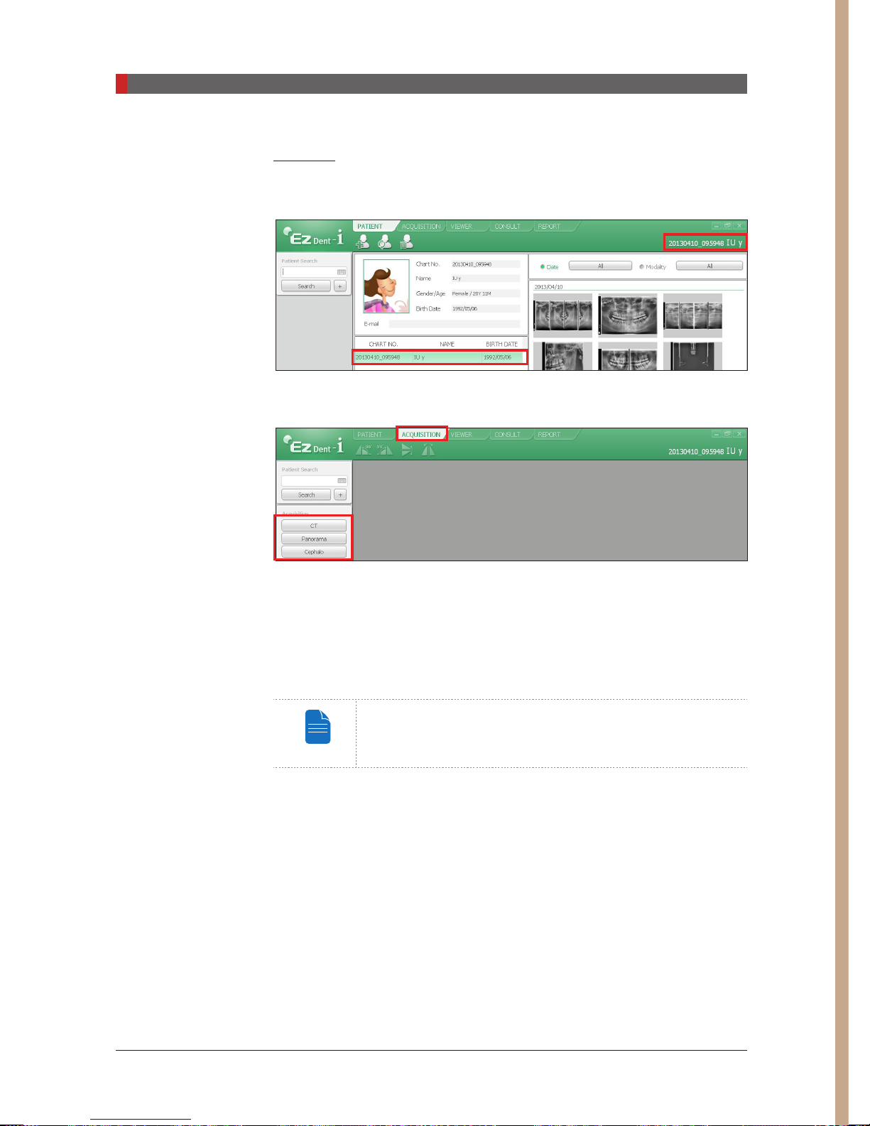
EzDent-i
A. Search and select the patient to be captured.
B. Click
Acquisition
and the imaging mode
(CT, Panorama, or Cephalo).
C. The main screen for the selected mode appears. (See
Software Overview
). From the main screen, you can configure the imaging
parameter settings prior to acquiring an image.
Please proceed to the next chapter.
Refer to chapters 6 - 8 for information regarding image
acquisition.
4.3 Imaging
70

6
Acquiring PANO Images
6.1
6.2
6.3
6.3.1 PANO Standard and Bitewing mode ..................................... 82
6.3.2 TMJ Open .............................................................................86
6.3.3 TMJ Close ............................................................................89
6.3.4 Sinus .....................................................................................90
6.4
PANO Imaging Program ...................................................... 72
Setting Exposure Parameters .............................................. 77
Positioning the Patient ......................................................... 81
Initiating X-ray Exposure ..................................................... 93

PaX-i3D Green (PHT-60CFO) User Manual
6 Acquiring PANO Images
6 Acquiring PANO Images
This chapter requires the preparatory steps in
completed. If you have not completed these steps, please return to
and complete the process outlined there before proceeding with this chapter.
6.1
PANO Imaging Program
EXAMINATION ARCH SELECTION
PANO
EXAMINATION
SPECIAL
EXAMINATION
Narrow
Normal
Wide
Child
Orthogonal
-
Chapter 5
Standard
Right
Front
Left
Standard
Right
Front
Left
Standard
Right
Front
Left
Standard
Right
Front
Left
Standard
Right
Front
Left
Bitewing
Bitewing Right
Bitewing Left
TMJ LAT Open
TMJ LAT Close
TMJ PA Open
TMJ PA Close
Sinus LAT
Sinus PA
to have already been
Chapter 5
EXAMINATION
PROGRAM
①
②
③
④
⑤
⑥
⑦
⑧
⑨
⑩
72
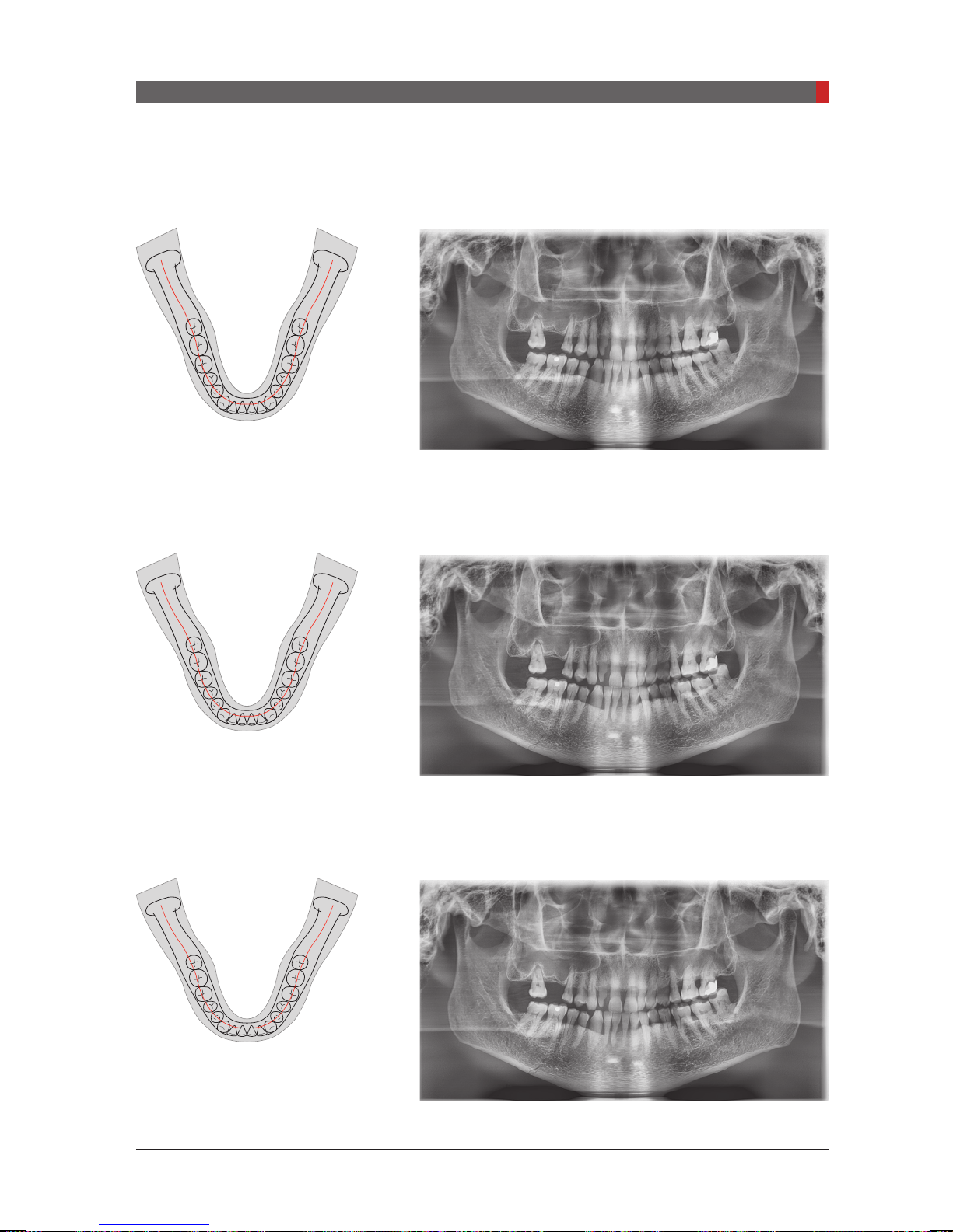
6 Acquiring PANO Images
①
Narrow_Standard
A panoramic imaging mode for the patients with the V-shaped
arch trajectory (typically for some females).
②
Normal_Standard
A panoramic imaging mode for the adult patients with the
normal arch trajectories.
PaX-i3D Green (PHT-60CFO) User Manual
③
Wide_Standard
A panoramic imaging mode for the patients with the squareshaped arch trajectory (typically for some males).
73

6 Acquiring PANO Images
④
Child_Standard
A panoramic imaging mode for the child arch trajectory, in
which case the X-ray exposure is 40% less than that in
mode.
⑤
Orthogonal_Standard
Normal
A panoramic imaging mode to minimize the overlapped
region of the teeth from the X-ray exposure which is beamed
perpendicularly between teeth.
74
PaX-i3D Green (PHT-60CFO) User Manual

6 Acquiring PANO Images
⑥
Orthogonal_Bitewing
A panoramic imaging mode to acquire an image only for the
region of interest through the orthogonal trajectory:
X-ray exposure than the Standard mode.
of an image of the maxillary sinus are not acquired.
Cons
Pros
: less
: TMJ and parts
X-ray ON
X-ray ON
X-ray ON
⑦
TMJ LAT Open / Close
An imaging mode to acquire a lateral image of the TMJ, in
which the X-ray beam is directed on the lateral TMJ region:
TMJ (Open and Close).
PaX-i3D Green (PHT-60CFO) User Manual
⑧
TMJ PA Open / Close (Optional)
An imaging mode to acquire a TMJ image, in which the X-ray
beam is directed on the frontal TMJ, with the patient's mouth
open fully and close (Open and Close).
75

6 Acquiring PANO Images
⑨
Sinus LAT (Optional)
A special imaging mode to acquire a Sinus image, in which
X-ray beam is directed on the lateral region of the maxillary
sinus.
⑩
Sinus PA
A special imaging mode to acquire a Sinus image, in which
X-ray beam is directed on the frontal region of the maxillary
sinus.
76
PaX-i3D Green (PHT-60CFO) User Manual

PaX-i3D Green (PHT-60CFO) User Manual
6 Acquiring PANO Images
NOTE
6.2
A
B
C
D
Setting Exposure Parameters
Perform the following procedures to select the capture parameters for the
specic patient and capture mode. For more details, refer to
Imaging Program
4.3.1 PANO.
You can set the imaging parameters on either the touch screen
or the imaging program running on the PC. They are synched
in real time and display the same environmental settings.
Touch Screen
E
A. Choose an imaging mode under
B. Select the mode under PANO Type:
Mode Details
Normal
Magic PAN
C. Select the image quality for the image.
Mode Details
HD
Normal
Normal image.
Image with ultra-high resolution optional
Image with higher resolution than Normal. Takes longer
scan time than the Normal.
Normal image
Imaging Mode.
Normal or Magic PAN.
77

PaX-i3D Green (PHT-60CFO) User Manual
6 Acquiring PANO Images
Click
Activated
D. Select the patient’s arch type under
Orthogonal
: This mode enables overlapping regions of teeth to be minimized when
Arch Selection
. By default,
Normal
is selected.
acquiring images in the ROI. If orthogonal arch is selected, its sub-modes are activated.
E. Select the ROI for panoramic image acquisition under
PANO Examination.
78
H F G

PaX-i3D Green (PHT-60CFO) User Manual
6 Acquiring PANO Images
NOTE
NOTE
NOTE
F. The patient’s gender will be automatically selected according to the patient
information registered in EasyDent / EzDent-i. Nevertheless, ensure that this
information is correct.
G. Select X-ray intensity.
Depending on the circumference of the patient’s head,
X-ray intensity may be classied as Hard, Normal, or Soft :
Soft ≤ Normal ≤ Hard
Age
Group
Child
Average head
circumference
53±3 cm
Range
(cm)
classication of head
circumference
> 53±3 Hard
53±3 Normal
53±3 < Soft
> 56±3 Hard
Adult
56±3 cm
56±3 Normal
56±3 < Soft
H. A default value for the tube voltage (kVp) and current (mA) will be displayed
based on the gender and X-ray intensity. If necessary, further adjustments can
be made using the arrows to the right of each number.
Adjustable resolution:
- Tube voltage: ± 1 kVp
- Tube current: ± 1 mA
I. Click the
CONFIRM
button for these parameters to take effect.
Please wait for a moment, while the rotating unit moves to
its initial scanning position.
79
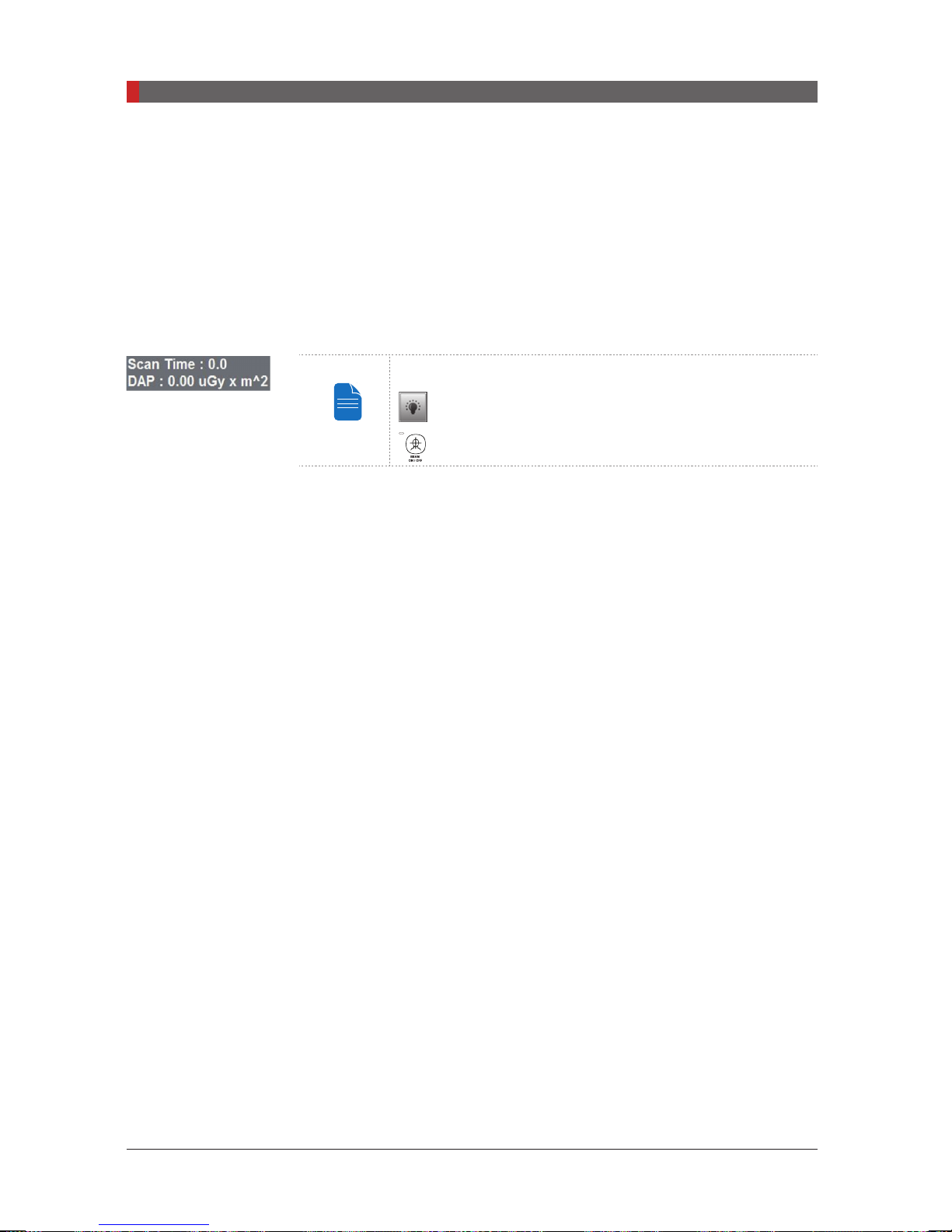
PaX-i3D Green (PHT-60CFO) User Manual
6 Acquiring PANO Images
NOTE
When you click the
READY
■The
CONFIRM
button,
button will begin blinking to show that it has been activated.
■The rotating unit will move to its initial scanning position.
■Three laser beams,
Mid-sagittal plane, Frankfurt plane and Canine
, will
be activated to facilitate patient positioning. These beams will disappear
after 20 minutes or if the
READY
button is clicked.
Laser beam On / Off buttons:
: Imaging Program
: Control Panel
■The scan time and DAP (Dose Area Product) values will be shown on the main
display for the selected exposure.
J. Guide the patient to the equipment. Position the patient within the
equipment. For further information about patient positioning, refer to section
6.3
Positioning the Patient.
80

PaX-i3D Green (PHT-60CFO) User Manual
6 Acquiring PANO Images
NOTE
CAUTION
WA
G
6.3
Positioning the Patient
Before Positioning the Patient
■Ask the patient to remove all jewelry and metallic objects, such as earrings,
hair pins, spectacles, dentures, and orthodontic appliances. These items
may cause shadow images which could obscure diagnosis.
■It is strongly recommended that the patient wear a lead apron for protection
against any possible scatter radiation.
■Adjust the column height to the patient’s height using the up/down button or switch.
Column Up Button
RNIN
Column up/down
Column Down Button
- In general, imaging is performed with the patient in
an upright position. However, a stool may be used for
imaging patients with special circumstances. If a stool is
used, ensure that the beams and movement of unit are
not obstructed by the stool.
- Correct positioning is an important factor in capturing
the best possible image. Proper positioning will reduce
the appearance of the cervical spine in the image.
If you don't adjust the laser beams for patient alignment
(vertical, horizontal, and canine beams), part of the image
may be zoomed in or out or a ghost may appear in the image.
Be careful not to project the laser beams directly into the
patient’s eyes as this could severely damage the patient’s
vision.
switch (optional)
81
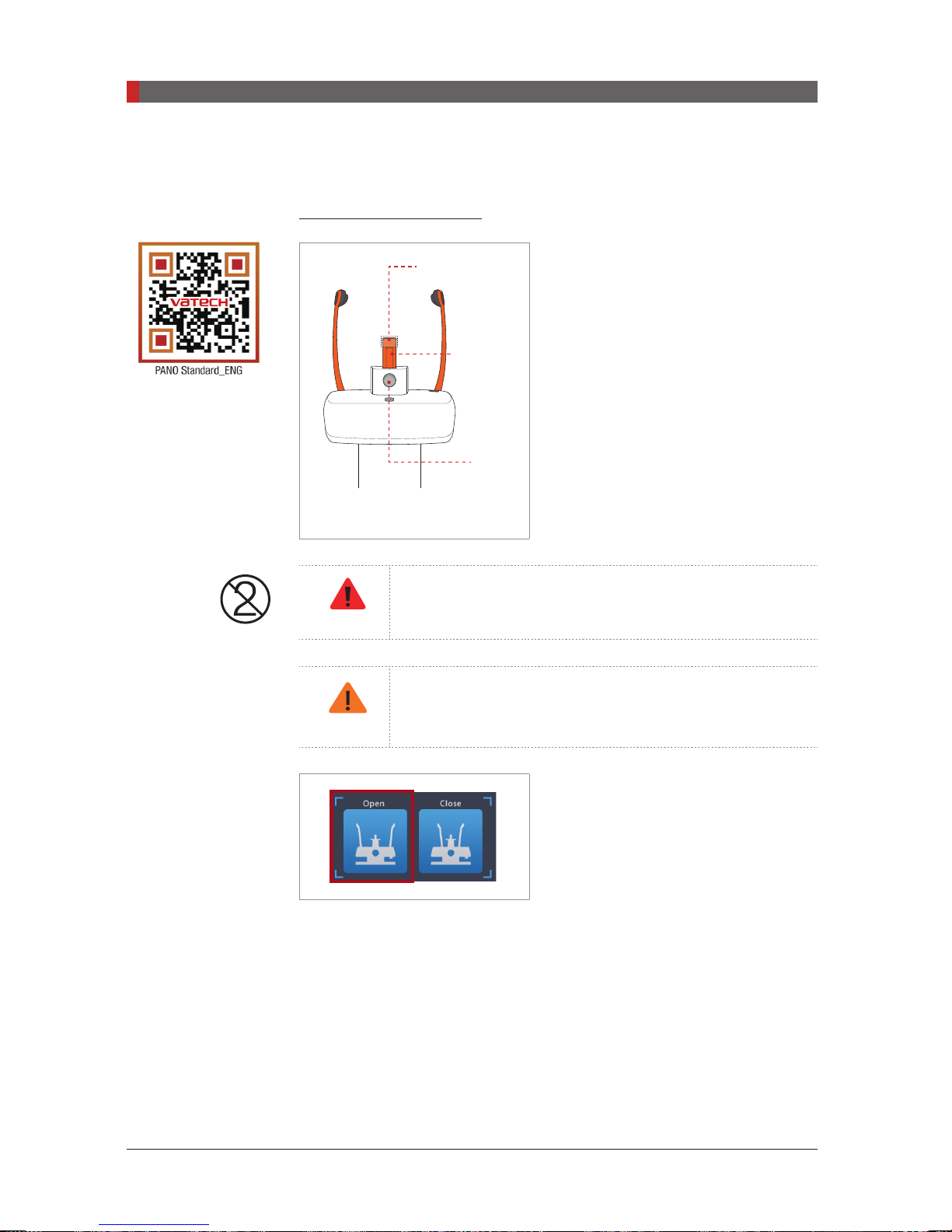
PaX-i3D Green (PHT-60CFO) User Manual
6 Acquiring PANO Images
WA
G
CAUTION
6.3.1 PANO Standard and Bitewing mode
Positioning the patient
A. Insert the bite block into the Chinrest
*To link to the video
manual: scan the
QR code with smart
phone or pad.
Hygiene cover
Bite block
Lock /
Release knob
for bite block
receptacle on the equipment.
B. Place a hygienic cover over the bite
block.
The hygiene cover for the bite block and chin support is
intended for single use only. Always replace the hygiene
RNIN
cover for each new patient.
Disinfect the Chinrest, Chin support and bite block using
an alcohol-based cleaning solution and wipe away all
residue with dry cloth.
C. Open the temple supports by clicking
the temple support adjustment button.
D. Guide the patient —facing the Chinrest — to the equipment.
E. Adjust the height of the column using the column up/down button or switch
(optional) until the patient’s chin rests comfortably on the Chinrest.
82
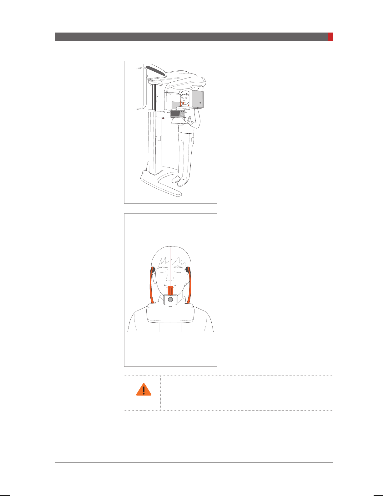
PaX-i3D Green (PHT-60CFO) User Manual
6 Acquiring PANO Images
CAUTION
F. Ask the patient to:
■
Stand upright
■
Firmly grip the handle
■
Lean his/her chest lightly against the
equipment
■
Position his/her feet slightly forward and
open stance
G. Ensure that the patient’s shoulders
remain level and that his/her neck is
relaxed. The cervical spine should be
straight and upright.
H. Have the patient bite the bite block
along its grooves using his/her upper and
lower incisors
I. Secure the bite block firmly by turning
the locking knob to the right.
J. Have the patient
■
Close his/her lips around the bite block
■
Keep his/her tongue pressed against
his/her palate
■
Close his/her eyes
Ask the patient to remain still until
scanning is completed.
To acquire the best image possible, ask the patient not to:
- Breathe or swallow saliva during image acquisition
- Move during image acquisition
83
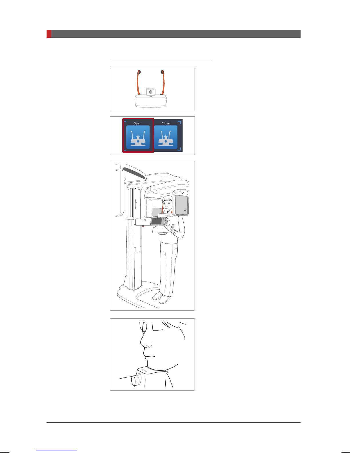
PaX-i3D Green (PHT-60CFO) User Manual
6 Acquiring PANO Images
Positioning the edentulous patient
A. Remove the bite block from the Chinrest
receptacle on the equipment.
B. Open the temple supports by clicking
the temple support adjustment button.
C. Guide the patient —facing the Chinrest
— to the equipment.
D. Adjust the height of the column using
the column up/down button or switch
(optional) until the patient’s chin rests
comfortably on the Chinrest.
E. Ask the patient to:
■
Stand upright
■
Firmly grip the handle
■
Lean his/her chest lightly against the
equipment
■
Position his/her feet slightly forward and
open stance
F. Have the patient
■
Close his/her lips around the bite block
■
Keep his/her tongue pressed against
his/her palate
84
■
Close his/her eyes
Ask the patient to remain still until
scanning is completed.
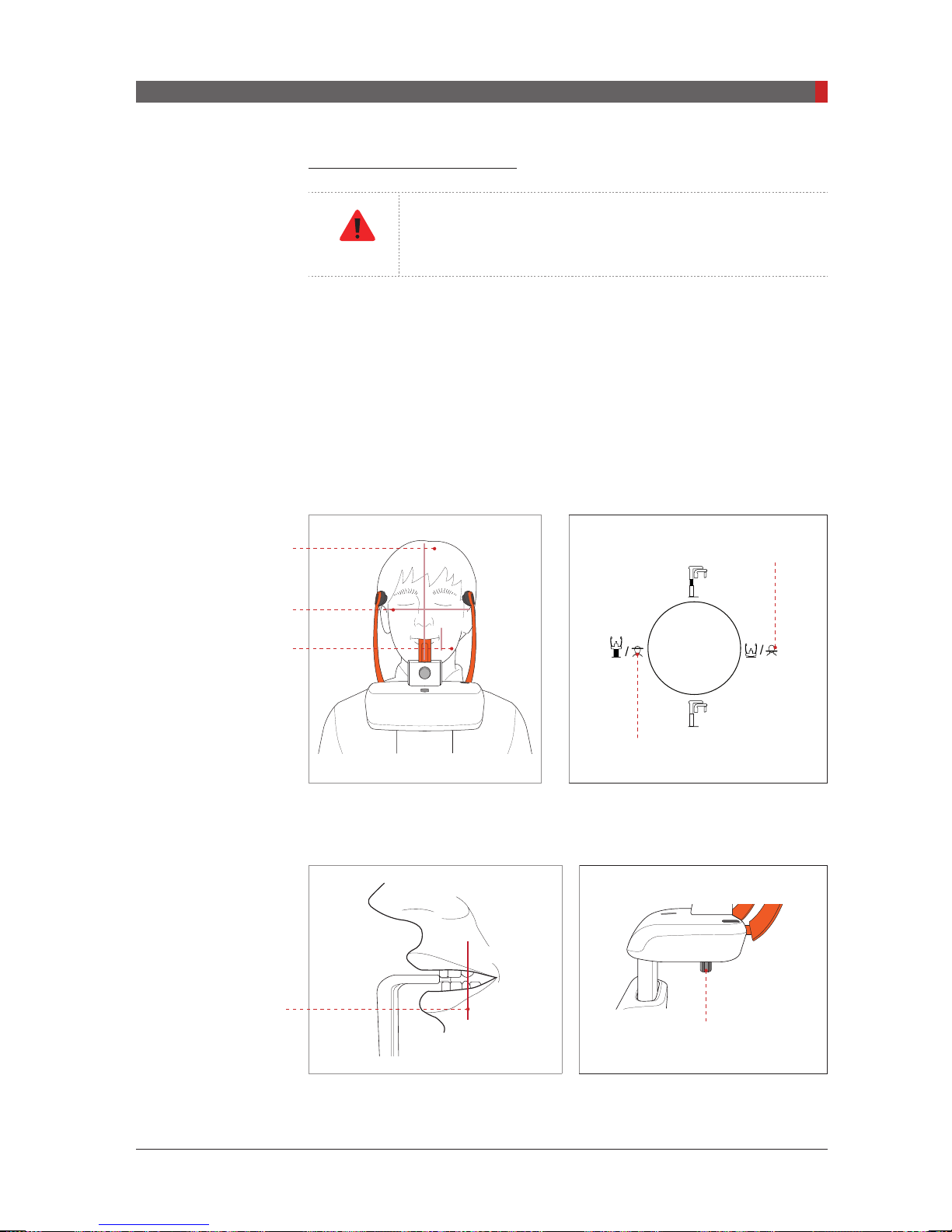
PaX-i3D Green (PHT-60CFO) User Manual
WA
G
Mid-sagittal plane
laser beam
6 Acquiring PANO Images
Aligning the Laser Beams
Be careful not to project the laser beams directly into the
RNIN
Mid-sagittal plane laser beam
A.
on the center of the patient’s face to prevent magnications of the left or right
side in the nal image.
Frankfurt plane laser beam
B.
Frankfurt plane is aligned with the Frankfurt plane laser beam.
* The Frankfurt plane is the plane which joins the infra-orbital point to the
superior border of the external auditory meatus.
patient’s eyes as this could severely damage the patient’s
vision.
: Position the Mid-sagittal plane laser beam
: Position the patient’s head so that the
Frankfurt plane laser
beam DOWN button
Frankfurt plane laser
beam
Canine laser beam
Canine laser beam
Frankfurt plane laser
beam UP button
Canine laser beam
C.
: Have the patient smile to properly position the canine
laser beam on the center of the patient’s canine tooth.
Canine laser beam lever
85
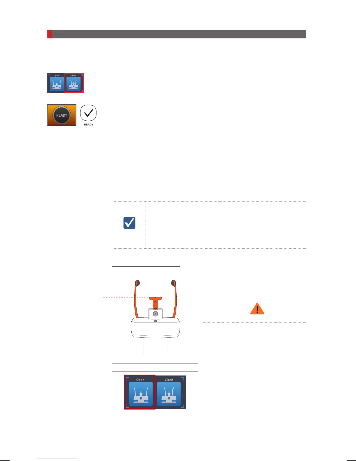
PaX-i3D Green (PHT-60CFO) User Manual
6 Acquiring PANO Images
CAUTION
Completing Patient Positioning
A. After conrming patient positioning and beam alignment, adjust the temple
supports to t snugly on both sides of the patient’s head by clicking the temple
support adjustment button.
B. Click the
READY
X-ray will be emitted at this point.
C. Proceed to section
6.3.2 TMJ Open
There are two TMJ sub modes:
image first and then scan a TMJ Close image. To prepare and position the
patient, follow the process outlined below.
IMPORTANT
Positioning the patient
button after the patient has been properly positioned. No
6.4 Initiating X-ray Exposure.
TMJ Open and TMJ Close
. Scan a TMJ Open
- Correct positioning is an important factor for image
capturing. Proper positioning will reduce the appearance
of the cervical spine in the reconstructed image.
- For a child with a large head circumference, Man/Woman
mode may be selected instead of Child.
A. Insert the Chin support into the Chinrest
receptacle on the equipment.
Chin support
Lock / release knob
for bite block
86
Disinfect the Chinrest using an
alcohol-based cleaning solution and
wipe away all residues with dry cloth
before proceeding any further.
B. Open the
Temple Supports
by clicking
the temple support adjustment button.
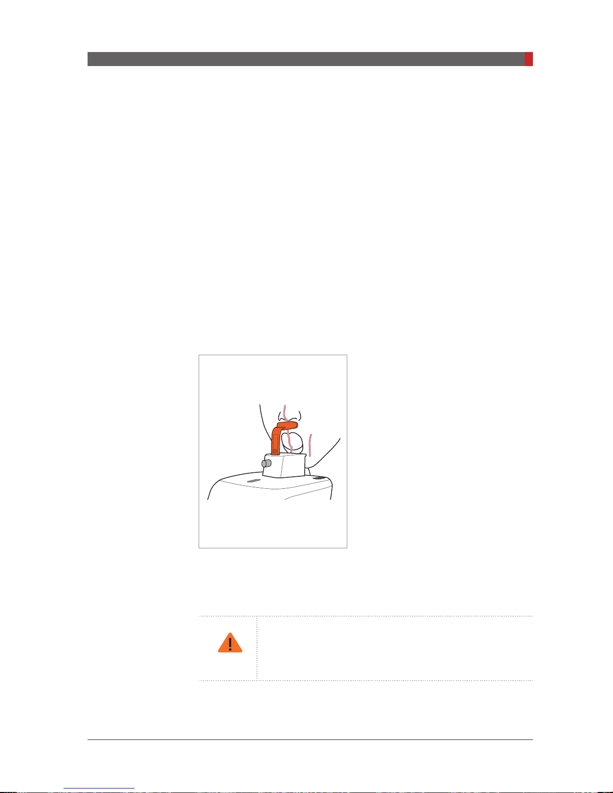
PaX-i3D Green (PHT-60CFO) User Manual
6 Acquiring PANO Images
CAUTION
C. Guide the patient —facing the Chinrest — to the equipment.
D. Adjust the height of the equipment using the column up/down button or
switch (optional) until the patient’s chin is resting on the Chinrest. Ensure that
the chin is in contact with the Chinrest.
E. Ask the patient to:
■Stand upright
■Firmly grip the handle
■Lean his/her chest lightly against the equipment
■Position his/her feet slightly forward.
F. Adjust the chin support so that it rests snugly on the chin and secure the chin
support rmly by turning the locking knob to the right.
G. Have the patient place his / her acanthion point on the chin support and tilt
his / her head forward by 5 degree.
H. For
TMJ Open
imaging, have the
patient:
■
Open his/her mouth as wide as possible
■
Keep his/her tongue positioned towards
the palate
■
Close his/her eyes.
Be careful the chin not to touch any part of
the equipment.
I. Ensure that the patient’s shoulders remain level and that his/her neck is
relaxed. The cervical spine should be straight and upright. Ask the patient to
remain still until scanning is complete.
To acquire the best image possible, ask the patient not to:
- Breathe or swallow saliva during image acquisition
- Move during image acquisition
87
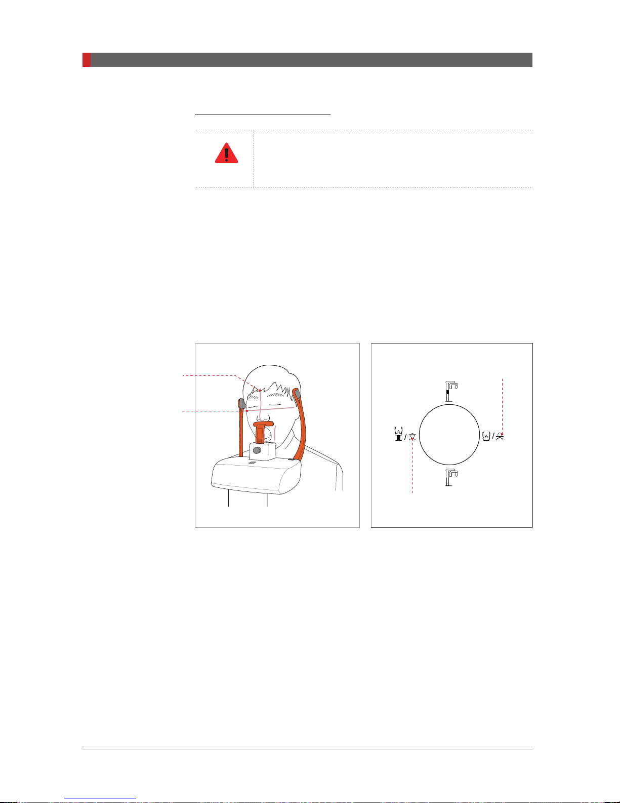
PaX-i3D Green (PHT-60CFO) User Manual
6 Acquiring PANO Images
WA
G
Aligning the Laser Beams
A.
at the center of the patient’s face to prevent magnications of the left or right
side in the nal image.
B.
Frankfurt plane is aligned with the Frankfurt plane laser beam.
* The Frankfurt plane is a plane which joins the lower eye lid to the
superior border of the external auditory meatus.
Be careful not to project the laser beams directly into the
patient’s eyes as this could severely damage the patient’s
RNIN
vision.
Mid-sagittal plane laser beam
Frankfurt plane laser beam
: Position the Mid-sagittal plane laser beam
: Position the patient’s head so that the
Mid-sagittal plane
laser beam
Frankfurt plane laser
beam
Frankfurt plane laser
beam DOWN button
Frankfurt plane laser
beam UP button
88
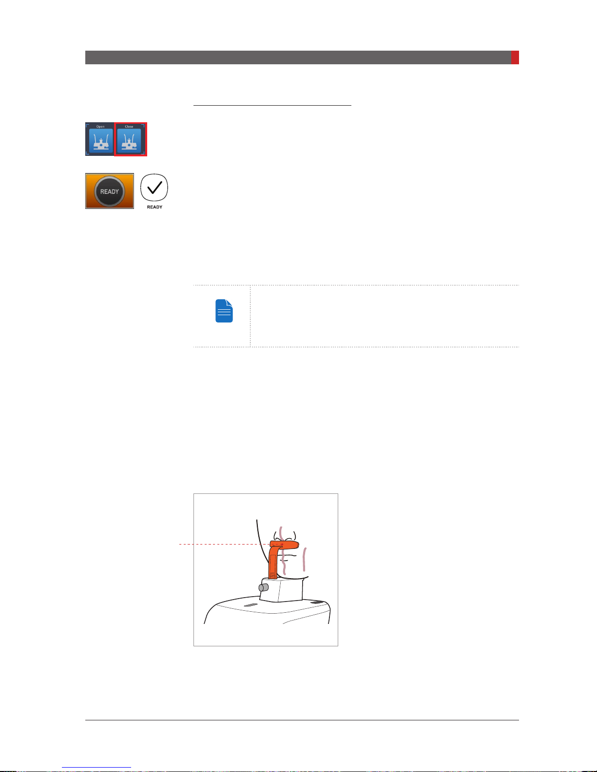
PaX-i3D Green (PHT-60CFO) User Manual
6 Acquiring PANO Images
NOTE
Completing Patient Positioning
A. After conrming patient positioning and beam alignment, adjust the temple
supports to t snugly on both sides of the patient’s head by clicking the temple
support adjustment button.
B. Click the
X-ray will be emitted at this point.
C. Proceed to section
READY
6.3.3 TMJ Close
A. Shortly after TMJ Open imaging has been completed, you will receive the
following message: “Do you want to take the TMJ Close image continuously?”
Press the OK button to capture a TMJ Close image.
B. Adjust the chin support so that it rests snugly on the chin and secure the chin
support rmly by turning the locking knob to the right.
C. Have the patient place his / her acanthion point on the chin support and tilt
his / her head forward by 5 degree.
button after the patient has been properly positioned. No
6.4 Initiating X-ray Exposure.
Scan a TMJ Open image first and then scan a TMJ Close
image. Guide the patient to close his/her lips for TMJ Close
imaging while maintaining the same position used for TMJ
Open imaging.
Acanthion Point
E. The laser beams should be aligned in the same way as for
F. Proceed to section
D. For TMJ Close imaging, Have the patient:
■
Close his/her mouth
■
Keep his/her tongue pressed against
his/her palate
■
Close his/her eyes
The top of the chin support must remain in
contact with the patient’s acanthion point
during exposure. Ask the patient to remain
still until scanning is complete.
6.4 Initiating X-ray Exposure.
TMJ Open
imaging.
89

PaX-i3D Green (PHT-60CFO) User Manual
6 Acquiring PANO Images
CAUTION
6.3.4 Sinus
Positioning the Patient
Chin support
Lock / release knob
for bite block
A. Insert the Chin support into the Chinrest
receptacle on the equipment.
Disinfect the Chinrest using an
alcohol-based cleaning solution and
wipe away all residues with a dry
cloth before proceeding any further.
B. Open the
temple support adjustment button.
the
C. Guide the patient —facing the Chinrest — to the equipment. Have the
patient stand upright in the center of the equipment.
D. Adjust the height of the equipment using the column up/down button or
switch (optional) until the patient’s chin rests comfortably on the Chinrest.
E. Ask the patient to:
■Stand upright
■Firmly grip the handle
■Lean his/her chest lightly against the equipment
■Position his/her feet slightly forward.
F. Adjust the chin support so that it rests upon snugly on the chin and secure
the chin support rmly by turning the locking knob to the right.
temple supports
by clicking
90
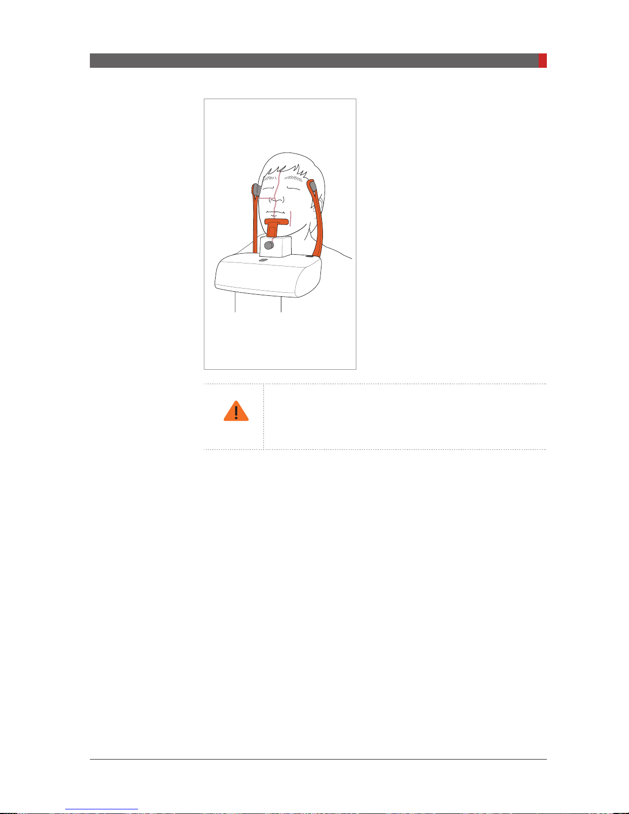
PaX-i3D Green (PHT-60CFO) User Manual
6 Acquiring PANO Images
CAUTION
G. Ensure that the patient’s shoulders
remain level and that his/her neck is
relaxed. The cervical spine should be
straight and upright.
H. Have the patient:
■
Tilt his/her head back by 10-15°
■
Close his/her mouth
■
Keep his/her tongue pressed against
his/her palate
■
Close his/her eyes
Ask the patient to remain still until
scanning is completed.
To acquire the best image possible, ask the patient not to:
- Breathe or swallow saliva during image acquisition
- Move during image acquisition
91

PaX-i3D Green (PHT-60CFO) User Manual
6 Acquiring PANO Images
WA
G
Mid-sagittal plane
laser beam
Frankfurt plane laser
beam
Aligning the Laser Beams
Be careful not to project the laser beams directly into the
patient’s eyes as this could severely damage the patient’s
RNIN
vision.
Mid-sagittal plane laser beam
A.
Position the Mid-sagittal plane laser
beam at the center of the patient’s face to
prevent magnifications of the left or right
side in the nal image.
Frankfurt plane laser beam
B.
: The
Frankfurt plane laser beam should go from
the top of the ear to the tip of the nose
when the patient’s head is tilted back 10 –
15 °.
:
Frankfurt plane laser
beam DOWN button
Frankfurt plane laser
beam UP button
Completing Patient Positioning
A. After conrming patient positioning and beam alignment, adjust the temple
supports to t snugly on both sides of the patient’s head by clicking the temple
support adjustment button.
B. Click the
X-ray will be emitted at this point.
READY
button after the patient has been properly positioned. No
C. Proceed to section
92
6.4 Initiating X-ray Exposure.

PaX-i3D Green (PHT-60CFO) User Manual
6 Acquiring PANO Images
WA
G
CAUTION
6.4
Initiating X-ray Exposure
The X-ray exposure method and its sequences are the same for PANO
Standard and PANO Special modes. The example used in this manual is the
PANO Standard mode.
To emit the X-ray, perform the following procedure.
RNIN
A. Leave the X-ray room and close the door. The operator must visually monitor
the patient at all times during image acquisition.
- Do not operate the PC during exposure. Failure to
comply with this instruction may cause the system to
malfunction.
- The operator shall observe the X-ray safety regulations
applicable to their area at all times during the operation
of this equipment.
If an emergency occurs during image acquisition, release
the exposure switch to cease X-ray emission.
Exposure indicator
light turns orange
Orange: Exposure
X-ray ON
B. Press and hold down the exposure switch until image acquisition is
complete.
During X-ray irradiation, ensure that
-
The LED lamp on top of the equipment
turns orange to indicate X-ray emission.
-
The warning lamp outside the X-ray
room turns on.
-
The sound (beep or music: optional)
goes off.
-
The radiation symbol on the upper left
corner of GUI turns yellow to indicate XRays are being emitted.
C. The image appears in real time on the imaging GUI.
93

PaX-i3D Green (PHT-60CFO) User Manual
6 Acquiring PANO Images
NOTE
Ex) Magic PAN
Two images are obtained, with each in the
respectively. You would click either button to compare them with each other.
The buttons:
D. Click the
Normal
Save
button to save the image.
Magic PAN (Optional): A high quality image reconstructed
from the optimal auto-focused images in each segment
throughout the panoramic region to correct the improper
patient positioning and rotating unit’s trajectory.
Magic PAN
Magic PAN
and
Normal
After Image Acquisition
After acquiring the image, complete the following steps:
■Loosen the temple supports to release the patient.
■Remove the hygiene cover from the bite block (for
only).
standard PANO
mode
94
■Press
Return
to bring the Rotating Unit back to its initial position.

7
Acquiring CEPH Images
7.1
7.2
7.2.1 Lateral / Full Lateral ............................................................101
7.2.2 Frontal (PA) ......................................................................... 102
7.2.3 SMV ....................................................................................104
7.2.4 Waters View ........................................................................105
7.2.5 CARPUS .............................................................................106
7.3
Setting the Exposure Parameters ........................................ 96
Positioning the Patient ....................................................... 100
Initiating X-ray Exposure ................................................... 107
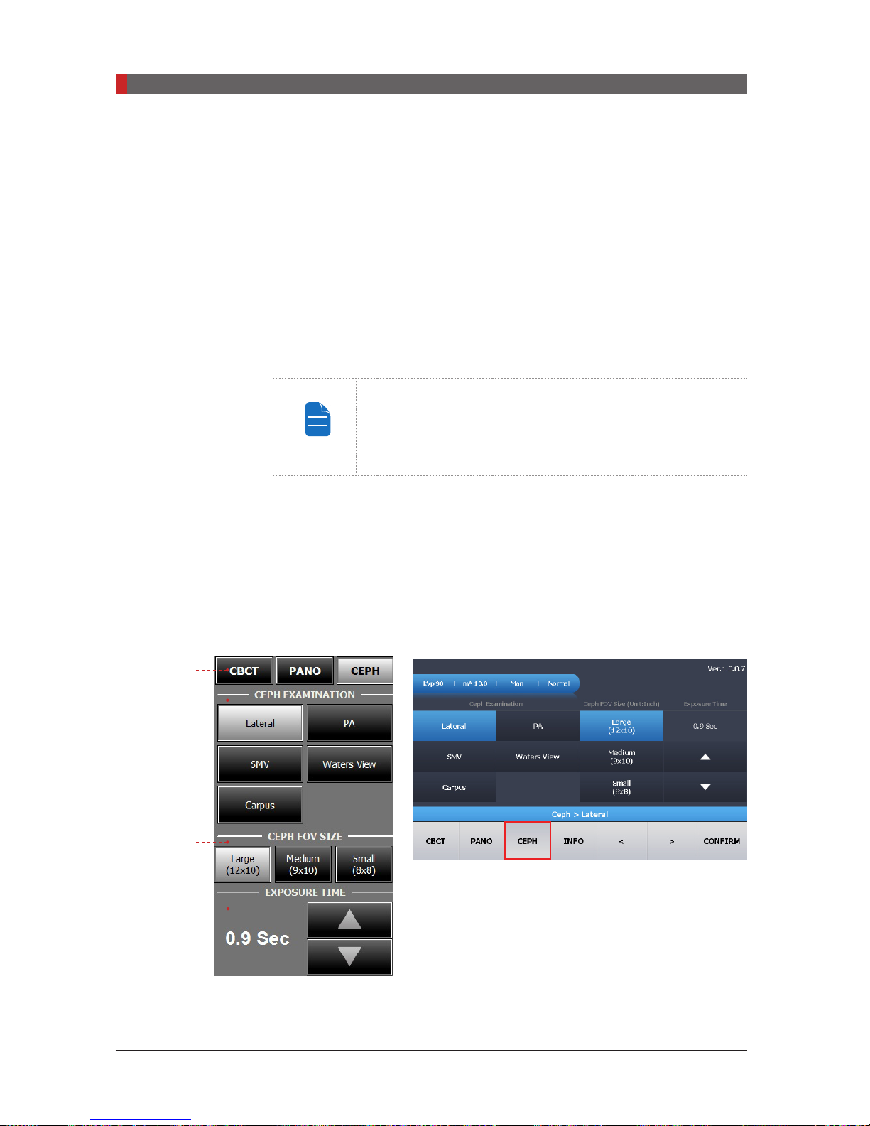
PaX-i3D Green (PHT-60CFO) User Manual
7 Acquiring CEPH Images
NOTE
7 Acquiring CEPH Images
This chapter requires all of the preparatory steps outlined in
already been completed. If these steps have not been completed, return to
Chapter 5
to the processes outlined in this chapter.
7.1
Setting the Exposure Parameters
Perform the following procedures to set the exposure parameters for the
specic patient and capture mode (for more details about CEPH imaging, refer
to section
Depending on the sensor type employed, one of three kinds of imaging S/W
comes with the equipment for the CEPH mode examination.
Chapter 5
and complete the setup processes outlined there before proceeding
You can set the imaging parameters on either the touch
screen or the imaging program running on the PC. They are
synched in real time and display the same environmental
settings.
4.3.2 CEPH
).
to have
Imaging Program
A
B
C
D
OP (1210 SGA sensor:
Oneshot Type)
Touch Screen
96
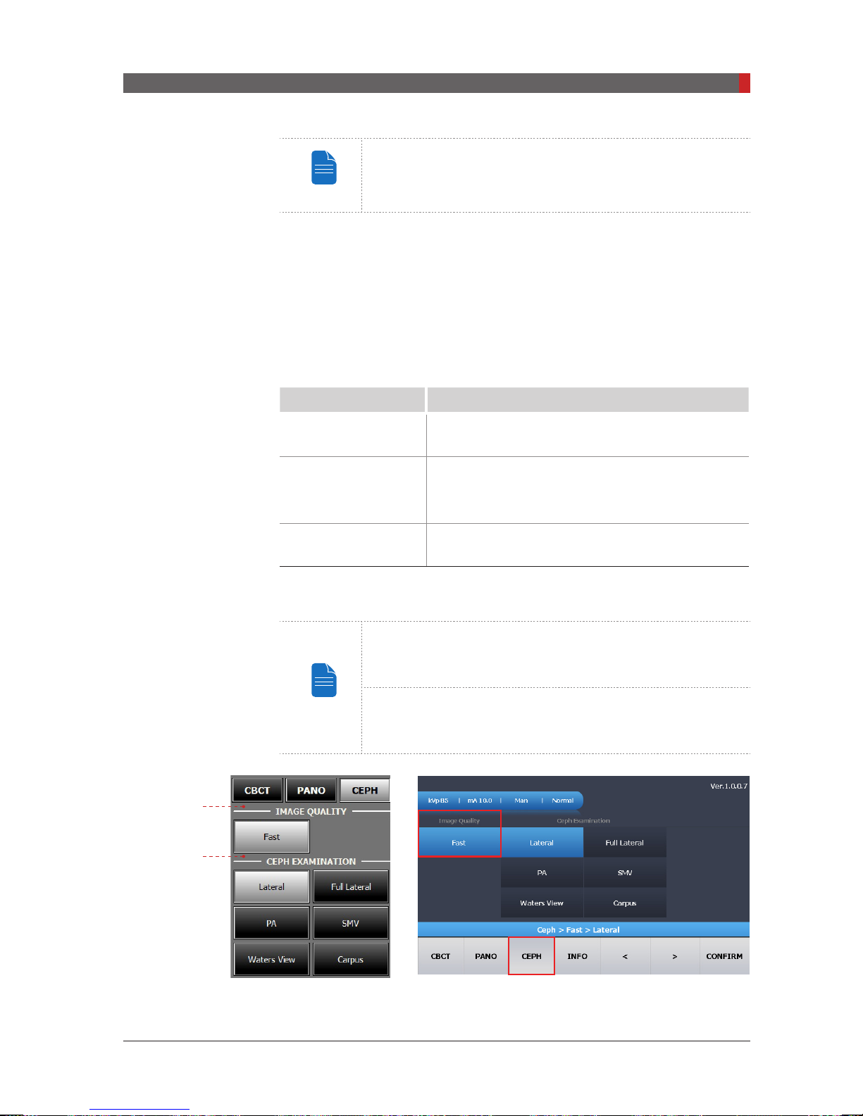
PaX-i3D Green (PHT-60CFO) User Manual
7 Acquiring CEPH Images
NOTE
NOTE
The Multi FOV is supported for the equipment with the one
shot type sensor.
A. Click the
B. Select the scanning mode under
CEPH
button.
CEPH Examination. – Lateral, Full
Lateral, PA, SMV, Waters View, Carpus.
C. Select the FOV size for the specic imaging mode.
[With one shot type sensor]
FOV Details
12 x 10 (inches)
30.48x25.40 (cm)
Full size
Region of the no interest of the rear part of the
9 x 10 (inches)
22.86x25.40 (cm)
head is eliminated to minimize the X-ray exposure
area.
8 x 8 (inches)
20.32x20.32 (cm)
EXPOSURE TIME
D.
Child
Exposure time can be adjusted by resolution of 0.1 s in the
range of 0.5 s to 1.2 s.
For information regarding to the exposure time of each
CEPH imaging mode, refer to the section “4.3.2 CEPH”.
①
②
SC (Xmaru2301CF Sensor
Scan Type)
97
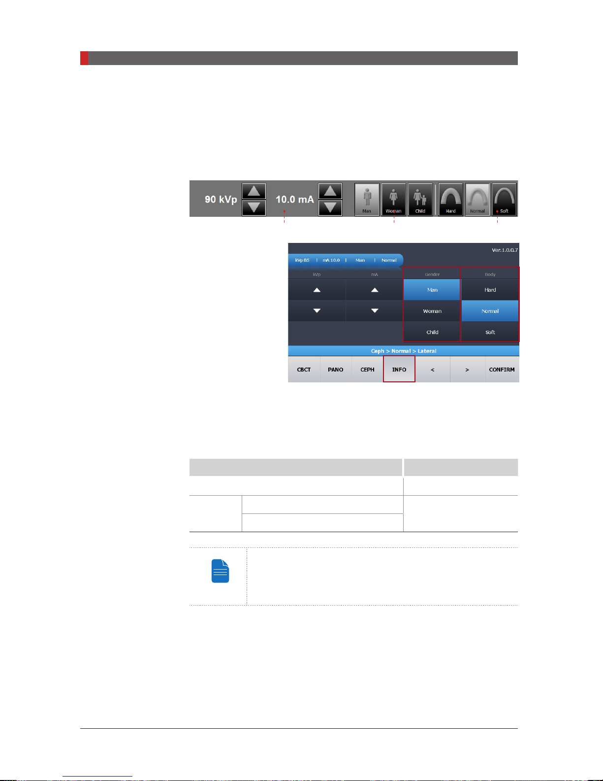
PaX-i3D Green (PHT-60CFO) User Manual
7 Acquiring CEPH Images
NOTE
①
Image Quality
Fast
: Scans faster with lower X-Ray dose than the
②
CEPH Examination
Full Lateral (Optional)
: Scan a lateral view image fully.
G E F
Normal
mode.
E. The gender and age of the patient is automatically selected according
to EasyDent / EzDent-i’s patient information. Nevertheless, ensure that this
information is correct.
Age Group VATECH’s Standard
Child
≤
12
Man
Adult
≥
13
Woman
A Child is defined as a person who is younger than 12
years old. If Child is selected, the image size and exposure
dose are automatically reduced.
98
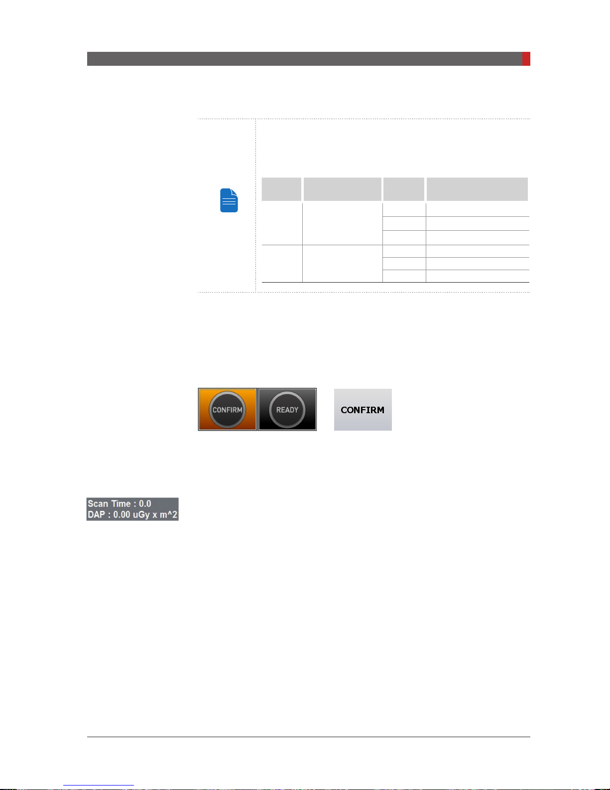
PaX-i3D Green (PHT-60CFO) User Manual
7 Acquiring CEPH Images
NOTE
F. Select
X-ray intensity.
Depending on the circumference of the patient’s head,
X-ray intensity may be classied as Hard, Normal, or Soft :
Soft ≤ Normal ≤ Hard
Age
Group
Child
Average head
circumference
53±3 cm
Range
(cm)
classication of head
circumference
> 53±3 Hard
53±3 Normal
53±3 < Soft
> 56±3 Hard
Adult
56±3 cm
56±3 Normal
56±3 < Soft
G. Default values for the tube voltage (kVp) and current (mA) will be displayed
based on the patient’s gender and X-ray intensity. If necessary, you may
manually adjust these values using the arrows to the right of each value.
H. Click
CONFIRM
to accept the parameters.
When you click the
READY
■The
CONFIRM
button:
button will begin blinking to show that it is activate.
■The scan time and estimated DAP (Dose Area Product) value are shown on
the main display for the intended exposure.
I. Guide the patient to the equipment. Refer to section
7.2 Positioning the
Patient.
99
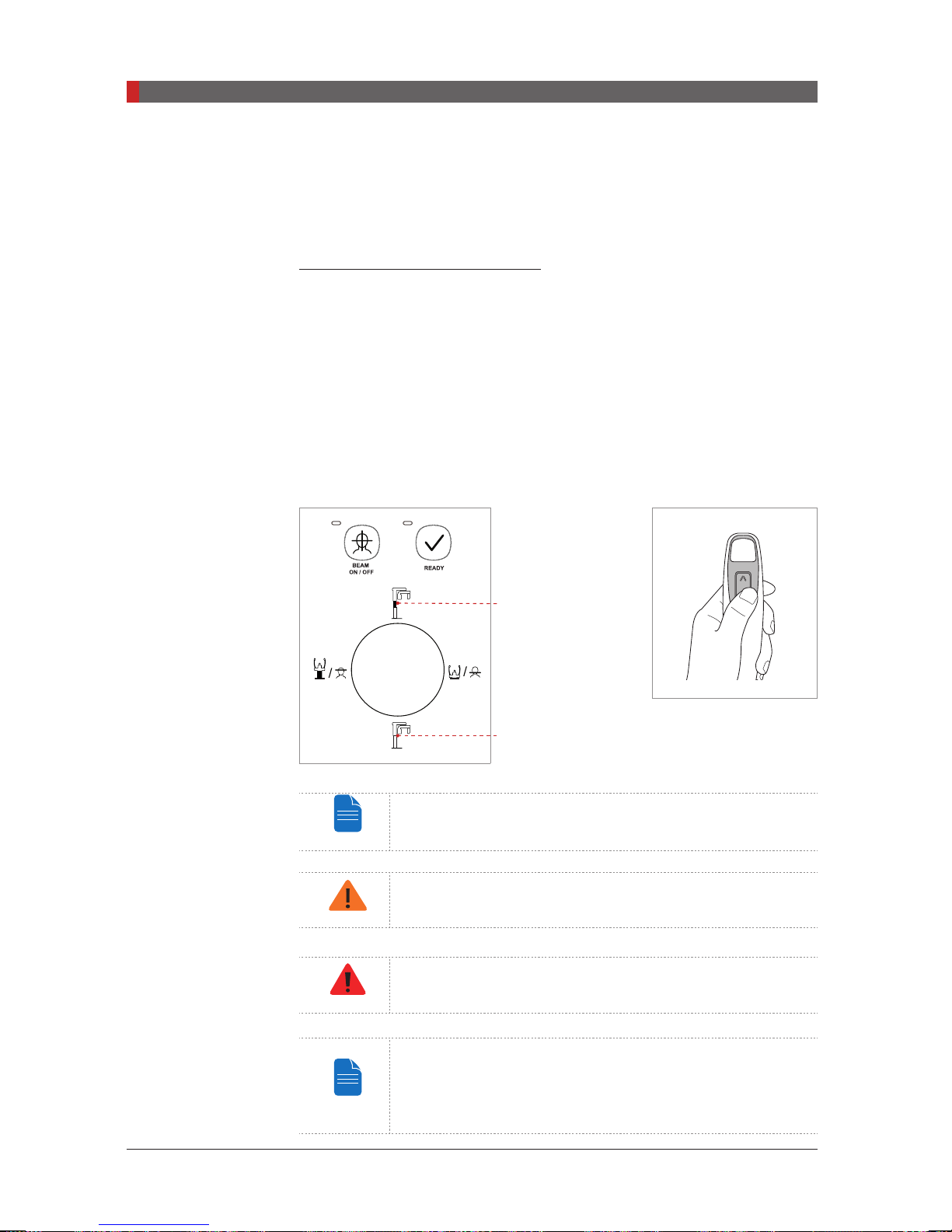
PaX-i3D Green (PHT-60CFO) User Manual
7 Acquiring CEPH Images
NOTE
CAUTION
WA
G
NOTE
7.2
Positioning the Patient
Follow the procedure below to prepare and position the patient for CEPH imaging.
Before Positioning the Patient
■Ask the patient to remove all jewelry and metallic objects, such as earrings,
hair pins, spectacles, dentures, and orthodontic appliances. These items
may cause shadow images which could obscure diagnosis.
■It is strongly recommended that the patient wear a lead apron for protection
against any possible scatter radiation.
■Adjust the column height to the patient’s height using the up/down button or
switch (optional).
Column Up Button
100
RNIN
Column up/down
Column Down Button
Correct positioning is an important factor in capturing the
best possible image.
Ensure that the nasal positioner left unfolded, before
adjusting the ear rods in the proper direction.
Ensure that the patient is clear of all moving parts while
adjusting the height of the equipment.
Although the illustrations and explanations on patient’s
posture and device usage are based on the OS / OP models
(one shot-type sensor), those for the SC (scan type) model
should be the same.
switch (optional)
 Loading...