


PaX-400C
Digital Panoramic & Cephalometric X-ray System
Installation Manual

PaX-400C Installation Manual
Greeting
Thank you for purchasing VATECH PaX-400 Series, Digital Panoramic & Cephalometric X-ray System.
In order to grant an adequate reference to use PaX-400 Series, Digital Panoramic & Cephalometric X-ray
System properly and safely, please read this installation manual carefully and keep it for future reference.
This installation manual may not reflect any changes in operating this product.
Warning
PaX-400 Series is a precise electro-mechanical system. Therefore, please read this
installation manual carefully before operation. VATECH (VATECH Co., Ltd.) is not
responsible for damages caused by computer trouble, improper installation, insufficient
maintenance procedures and wrong operations.
VA TECH Co., Ltd. 1

PaX-400C Installation Manual
Contents
1. Introduction.................................................................................5
1.1 Specifications ......................................................................................... 5
1.2. Obligation .............................................................................................. 7
1.2.1. Obligation of Installers...........................................................................................7
1.2.2. Safety Issues.........................................................................................................7
1.3. Layout.................................................................................................... 8
1.3.1. Panoramic X-ray System.......................................................................................8
1.3.2. Panoramic & Cephalometric X-ray System ...........................................................9
1.3.3. Structure..............................................................................................................10
2. Preparation................................................................................12
2.1. Checking “ShockWatch” and “TiltWatch”............................................. 12
2.2 Checking carton boxes......................................................................... 13
2.2.1. The sizes of the boxes.........................................................................................13
2.2.2. Accessories .........................................................................................................15
2.2.3. Installation Tools .................................................................................................18
3. Installation.................................................................................20
3.1 Main installation.................................................................................... 20
3.1.1. Checking ground balance....................................................................................20
3.1.2. Base and Column................................................................................................21
3.1.3. Rotating Unit........................................................................................................25
3.1.4. Cephalo unit (C1/C2)...........................................................................................27
3.1.5. Cephalo unit (CAN communication-Optional)......................................................31
3.1.6. Others..................................................................................................................36
4. Setting PC..................................................................................44
4.1. Installing LAN card and Serial card ..................................................... 44
4.1.1. LAN card Installation ...........................................................................................44
4.1.2. Serial card installation .........................................................................................44
4.2. Connecting LAN cable and Serial cable.............................................. 45
4.2.1. LAN cable............................................................................................................45
4.2.2. Serial cable..........................................................................................................45
VA TECH Co., Ltd. 2

PaX-400C Installation Manual
4.3. Driver setting ....................................................................................... 46
4.3.1. LAN card .............................................................................................................46
4.3.2. Serial card ...........................................................................................................46
4.4. Software installation ............................................................................ 50
4.4.1. EasyDent V4 .......................................................................................................50
4.4.2. Device .................................................................................................................55
4.4.3. Manual.................................................................................................................56
4.4.4. Set the device on EasyDent V4...........................................................................57
4.5. IP setting ............................................................................................. 65
4.5.1. Setting IP address ...............................................................................................65
4.5.2. Checking connection with PaX-400C ..................................................................67
4.6. HyperTerminal setting ......................................................................... 68
4.6.1. Setting HyperTerminal.........................................................................................68
4.6.2. Checking connection with PaX-400C ..................................................................70
5. Testing image............................................................................72
5.1. The test using Hyper Terminal ............................................................ 72
5.1.1. Commands to test communication between PC and PaX-400C .........................72
5.2. The Test using Capturing program...................................................... 73
5.3. Capturing Image (Final test)................................................................ 76
6. Warranty ....................................................................................77
VA TECH Co., Ltd. 3

PaX-400C Installation Manual
1
Chapter 1 Introduction
This chapter describes the overall information about PaX-400C
VA TECH Co., Ltd. 4

PaX-400C Installation Manual
1. Introduction
1.1 Specifications
1.1.1. Model
● PaX-400 Panoramic only
● PaX-400C1 Panoramic & Cephalometric system with one sensor
● PaX-400C2 Panoramic & Cephalometric system with two sensors for each unit
1.1.2. Standard Accessories
● Bite
● Chin supporter
● Up/Down switch
● X-ray exposure switch with extensible cable
● Hygiene bag
1.1.3. System Requirements for PC
● PC for Capturing Image
① Operating System Microsoft XP Home Edition Service Pack 2
② CPU Intel Pentium 4, 630 processor 3.0GHz
③ HDD 250 GB (prefer bigger capacity)
④ Main Memory 512MB DDR2
⑤ Video Memory 128 MB 128bit
⑥ Network 2 EA of 10/100/1000 Gigabit
⑦ Serial 2 EA of RS232 serial port
(One serial card is provided by VATECH, the other is on main board)
⑧ DVD+/-RW
⑨ Monitor Minimum resolution 1024x768
● PC for viewing image
① Operating System Microsoft XP Home Edition Service Pack 2
② CPU Intel Pentium 4 630 processor 3.0GHz
③ Main Memory 512MB DDR2
④ Network 1 EA of 10/100/1000 Gigabit
⑤ DVD+/-RW
⑥ Monitor Minimum resolution 1024x768
VA TECH Co., Ltd. 5

PaX-400C Installation Manual
1.1.4. Mechanical size
● Weight
① Model without cephalometric unit 200.00 kg
② Model with cephalometric unit 250.00 kg
● Total height 2,240 mm
● Type of installation Base Stand/Wall Mount
1.1.5. Electrical specifications
● Power supply voltage AC 110/230V ± 10%
● Frequency 50/60 Hz
● Power consumption 1.3KVA
1.1.6. Environmental specifications
● Operating temperature 10 - 40℃
● Operating relative humidity 30 – 75%
● Transport and storage temperature -20 - 70℃
● Transport and storage relative humidity < 90% non-condensing
CE symbol grants the product compliance to the European Directive for Medical
Devices 93/42 as a class IIB device. Authorized by Grand-Duche De Luxemburg.
VA TECH Co., Ltd. 6

PaX-400C Installation Manual
1.2. Obligation
PaX-400 is a Digital Panoramic System, and PaX-400C1 is a Digital Panoramic & Cephalometric System
with 1 sensor, and PaX-400C2 is a Digital Panoramic & Cephalometric System with 2 sensors based on
the latest technology.
1.2.1. Obligation of Installers
PaX-400 Series should be installed by the people of VATECH and/or trained by VATECH. And the
installers have obligation as follow:
① Make sure that the line voltage specified by the manufacturer is used only (110 /230V±10%,
50/60Hz).
② Confirm 3 ground connectors.
③ For safety reasons, make sure to turn off the main power switch of the system during installing
④ Install and test the system as per the installation instructions.
1.2.2. Safety Issues
● Electrical issues
① Only trained and qualified technicians are allowed to open the product and have access to any
circuit boards of the system
② Power supply lines must be complied with safety regulations and be maintained with ground
terminals for protecting the parts from the electrical shocks.
③ Turn off the system and/or unplug the power cable before cleaning or disinfecting the unit.
● Mechanical issues
① Make sure that fingers, or other parts of the patient, or the operator are not pinched during
installation.
● Explosion
① The system should be placed and used far away from flammable gases, cables with high electrical
power or vapors
● Radiation
① Only trained and qualified persons are allowed to operate the system by the law of radiation
protection.
② Make sure that the system should be operated with careful observation.
● Environmental issue
① The system must be disposed according to the existing law in your country.
VA TECH Co., Ltd. 7

PaX-400C Installation Manual
1.3. Layout
1.3.1. Panoramic X-ray System
VA TECH Co., Ltd. 8

PaX-400C Installation Manual
1.3.2. Panoramic & Cephalometric X-ray System
VA TECH Co., Ltd. 9

PaX-400C Installation Manual
1.3.3. Structure
This section contains the explanation on main structure of PaX-400C. This helps you understand the
installation easily
4
2
1
3
5
No. Part Name Function Carton Box No
1 Rotating unit Assemble Rotating unit to Column. Carton Box.1
2 Vertical carriage Connected with Column and holding Rotating unit Carton Box 1
3 Column There is weight block inside to make weight balance. Carton Box.2
4 Cephalo unit Assemble Cephalo unit to back side of the Column. Carton Box.3
5 Base Upholding plate for Column Carton Box.3
VA TECH Co., Ltd. 10

PaX-400C Installation Manual
Chapter 2 Preparation
This chapter describes what should be done before installation
2
VA TECH Co., Ltd. 11
PaX-400C Installation Manual
2. Preparation
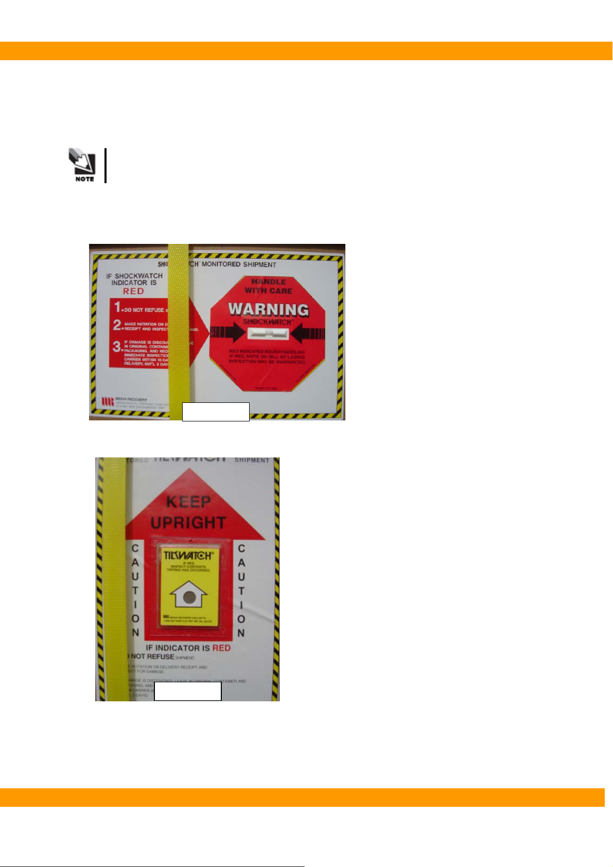
2.1. Checking “ShockWatch” and “TiltWatch”
The “ShockWatch” and “TiltWatch” become red in case of damaged.
● Check whether each box of “ShockWatch” and “TiltWatch” has been damaged or not.
If “Yes”, contact your shipping company, agent or VATECH.
ShockWatch
TiltWatch
VA TECH Co., Ltd. 12
PaX-400C Installation Manual
2.2 Checking carton boxes
Check whether each part is in a good condition or not
If not, contact your agent or VATECH.
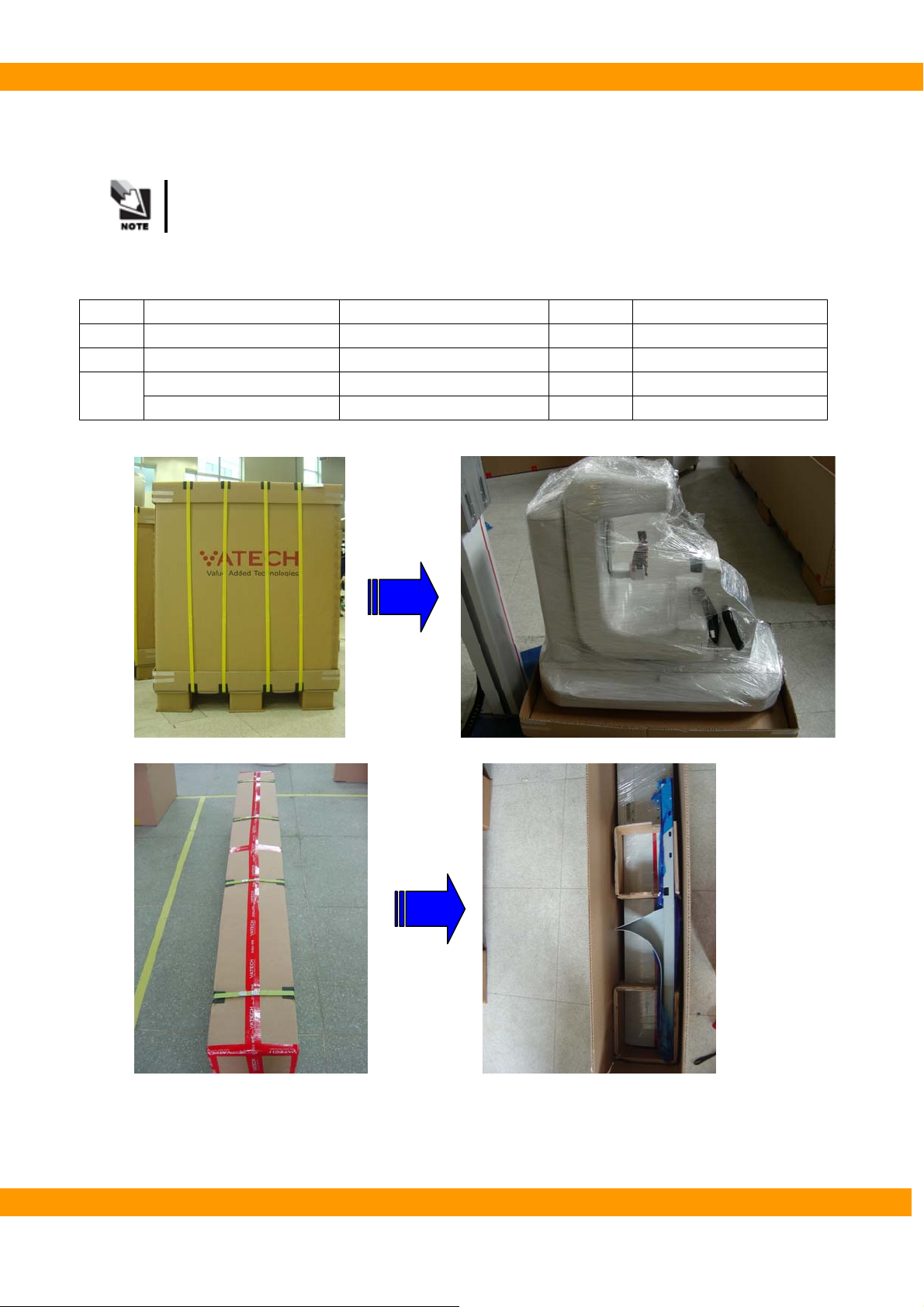
2.2.1. The sizes of the boxes
No Name of Box Dimension Weight Remarks
1 Rotating unit 580 X 1000 X 1200(mm) 92kg
2 Column 300 X 2300 X 500(mm) 100kg
Cephalo & Accessories 900 X 1650 X 700(mm) 120kg Cephalometric model 3
Accessories 800 X 1000 X 800(mm) 83kg Panoramic model
[Rotating unit box]
[Column box]
VA TECH Co., Ltd. 13

PaX-400C Installation Manual
[Ceph & Accessories box]
VA TECH Co., Ltd. 14

PaX-400C Installation Manual
2.2.2. Accessories
● Accessories
No. Description Specifications Q’TY(EA) Remarks
1 Exposure switch X-ray exposure 1
2 Up/Down switch Up/Down 1
3 Switch holder 2
4 Bite supporter 2
5 Bite Normal 2
6 Bite for toothless patient 1
7 Bite for TMJ 2 Large(1ea)/Small(1ea)
8 Hygiene bag 1
9 Plastic case For Multi-use 5
10 Extension cable For exposure switch 1 5m
11 Coupler 1 6pins(RJ11)
12 Sensor module 1
5
8
6
12
7
9
3
1 2
4
10
11
VA TECH Co., Ltd. 15

PaX-400C Installation Manual
● Cases
No. Description Location Remarks
1 Rotating Unit Case (lower, large) Ceph & Accessories box
2 Rotating Unit Case (upper, small) Ceph & Accessories box
3 Handle Frame cover Ceph & Accessories box
4 Wall Bracket set Ceph & Accessories box
5 Cable chain Ceph & Accessories box
6 Base cover Ceph & Accessories box
7 Base arm cover Column box
8 Hand plate set for Carpus Ceph & Accessories box
7
23 4
8
1
5
VA TECH Co., Ltd. 16
PaX-400C Installation Manual
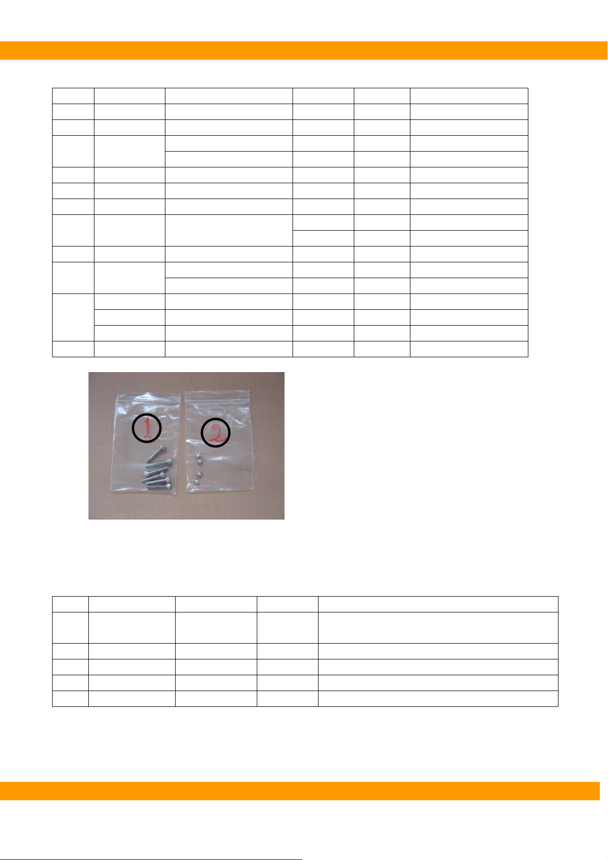
● Bolts
No. Description Usage Dimension Q’ty(ea) Remarks
1 Wrench Column and Base 6*35 6
2 Truss Cable chain 4*6 4
3 Wrench
4 Wrench Cephalo unit 8*35 4 Ceph model only
5 Screw Rotating unit(Small) 4*12 5 With speed nut
6 Flat headed Rotating unit(Large) 4*12 6
7 Truss Handle cover
8 Level Foot Base arm 1
9 Wrench
Wrench Wall bracket 8*15 4 With Spring & Flat washer
10
11 Flat head Switch holders 6
Screw Wall bracket 8
Nut Wall bracket Ø8 4
Rotating Unit(Upper) 8*25 3
Rotating Unit(Lower) 8*20 2
4*10 2
4*16 4
Column &Base/Base arm 8*15 3
Base arm 6*40 2
With Spring & Flat washer
1
2
● PC accessories
No. Description Usage Q’ty(ea) Remarks
1 CD Installation 1 Check whether the S/N of CD and PaX-400C is the
same or not
2 LAN card 2 1EA for Panoramic model
3 Serial card 1
4 LAN cable Signal transfer 2 1EA for Panoramic model
5 RS232 cable 1
VA TECH Co., Ltd. 17

PaX-400C Installation Manual
2.2.3. Installation Tools
No Name
1 L-Wrench set 1.5/2/2.5/3/4/5/6/8/10 MM (9 PCS) 1Set 1Set
2 Monkey Spanner 8” 1EA
3 Digital tester
(Multi Meter)
4 Driver Long, Middle, Short 1Set Cross type
5 Cutter 1EA
6 Long Nose Flier 1EA
7 Side Cutting Flier 1EA
8 Iron Block 1EA For Leveler
9 Leveler 1EA SB300
1 2
Specifications
1EA AC/DC Tester
Q’ty (ea) Remark
8
5
3
9
4
4
4
6
7
VA TECH Co., Ltd. 18

PaX-400C Installation Manual
3
Chapter 3 Installation
This chapter descries how to install PaX-400C properly and safely in detail
VA TECH Co., Ltd. 19

PaX-400C Installation Manual
3. Installation
3.1 Main installation
3.1.1. Checking ground balance
① Take out Base from the box
Base
② Check the balances of place to install the system.
Front
Rear
Right
Left
Check the balances of the floor where the system will be installed. The floor does
not need to be made perfect balance, but it should not be too slant for the system
as the balance is very important for the system.
VA TECH Co., Ltd. 20

PaX-400C Installation Manual
3.1.2. Base and Column
① Take out Column from the box and place it on the front side upwards over the Styrofoam plates.
At least 3 persons are needed to install PaX-400 Series. Some assistances may be
needed when lifting Column from the box.
Styrofoam is to prevent from scratches on the column or damages of the limit
switch on the back of Column.
VA TECH Co., Ltd. 21
PaX-400C Installation Manual
② Check whether the stopper is locked tight or not.
③ Install Base to Column and tighten the bolts: Insert 6 bolts [M6*35](see volt bag No.1) through
Base to Column.
Minimum two persons should hold Column when screwing bolts.
④ Remove the Styrofoam plate near Base.
VA TECH Co., Ltd. 22
PaX-400C Installation Manual
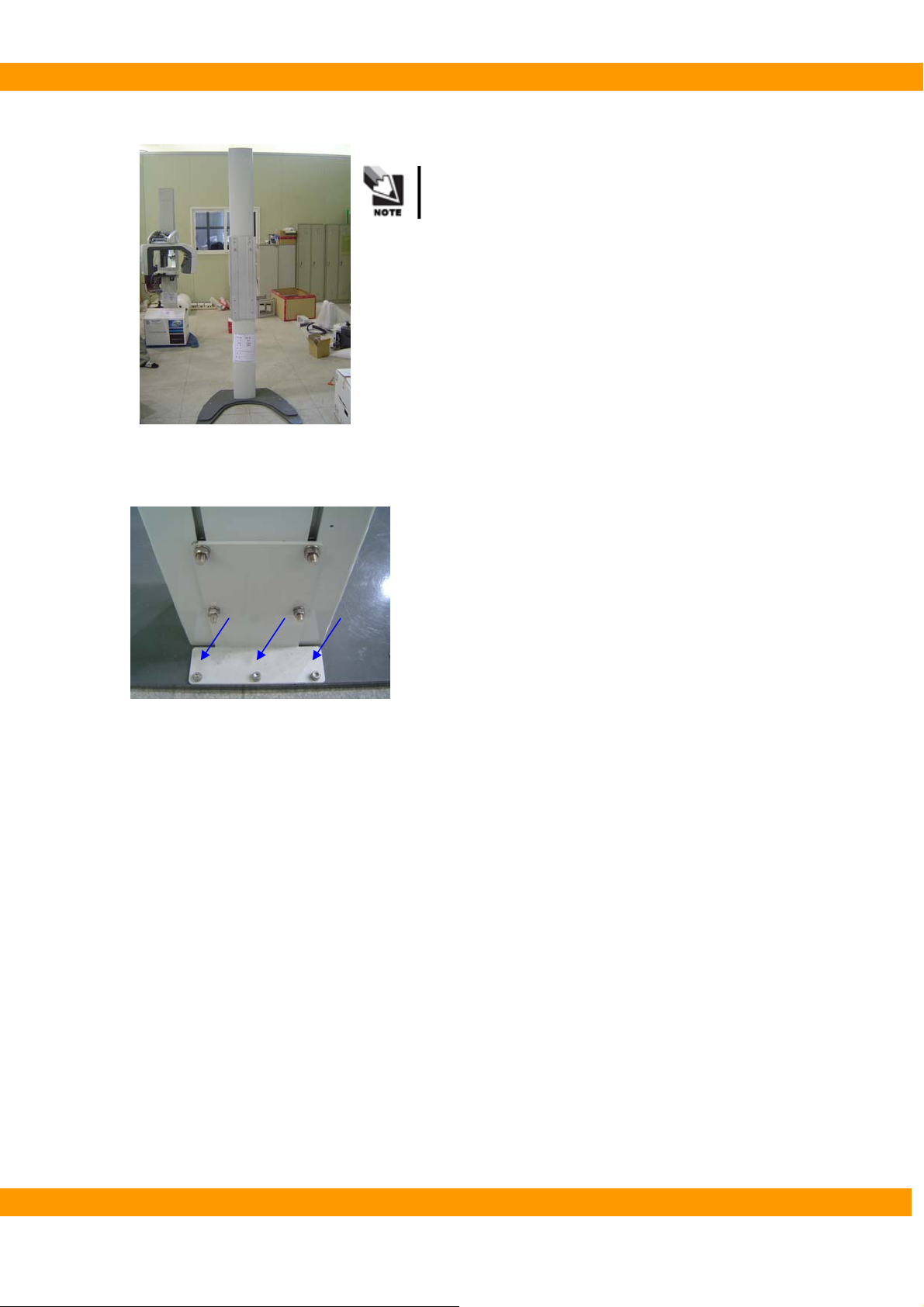
⑤ Stand Column on the ground.
Minimum two persons are needed for this work.
⑥ Insert 3 bolts [M8*15](See bolt bag No.9) to rear of Base.
VA TECH Co., Ltd. 23

PaX-400C Installation Manual
⑦ Install chain ass’y on Column
-. Insert 2 bolts [M4*6] (see bolt bag No.2) through chain ass’y into column. [ A PART ]
-. Insert 2 bolts [M4*6] (see bolt bag No.2) through chain ass’y into column. [ B PART ]
A PART
B PAR T
VA TECH Co., Ltd. 24

PaX-400C Installation Manual
3.1.3. Rotating Unit
① Take out Rotating unit from the box
② Assemble Rotating unit
Check two holes of the back of the Rotating unit and two projections of Column.
Connect Holes on Rotating unit into the projections on Column.
Minimum three persons are needed to install Rotating unit.
VA TECH Co., Ltd. 25
PaX-400C Installation Manual
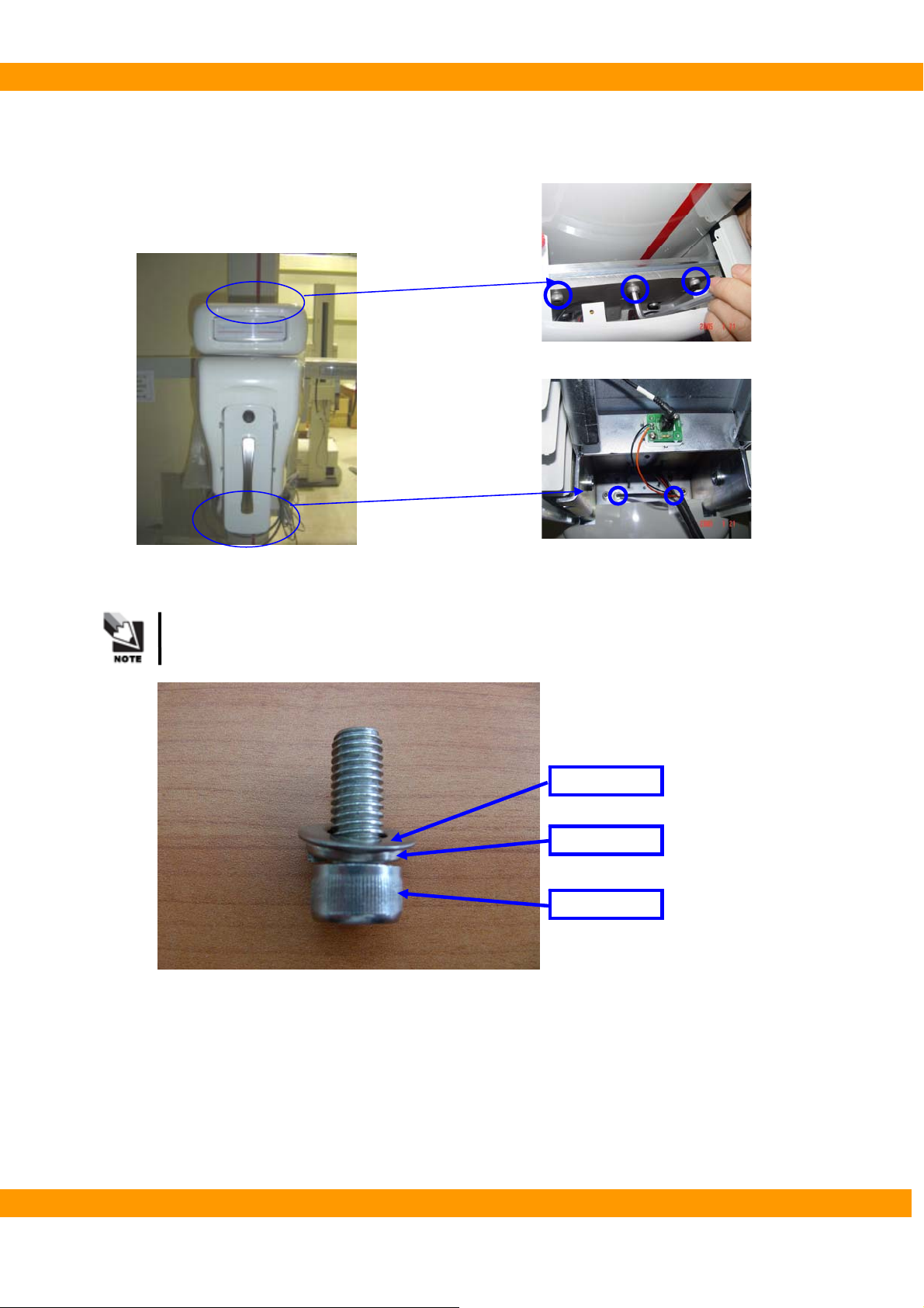
② Fix Rotating unit to Column with bolts (see volt bag No.3).
- Insert 3 bolts [M8*25] on A part
- Insert 2 bolts [M8*20] on B part (with Spring washers and Plain washers)
A
B
See a bolt with washers for the correct usage as below
Flat washer
Spring washer
Wrench bolt
VA TECH Co., Ltd. 26

PaX-400C Installation Manual
3.1.4. Cephalo unit (C1/C2)
Cephalo
① Remove Fix-plate with wrench.
② Insert the wrench bolt again for fixing weight balance.
When taking out the wrench bolt to remove
Fix-plate, make sure to hold Handle
Frame so that Rotating unit does not go up.
VA TECH Co., Ltd. 27

PaX-400C Installation Manual
③ Fix Cephalo unit to Column
3
2
Screw the bolts as the picture above.
Minimum 3 persons are needed to install Cephalo unit.
④ Connect the cables of Cephalo unit.
1
4
⑤ Assemble Wall-bracket as the picture below. Insert 2 bolts, 2 spring washers and 2 nuts.
VA TECH Co., Ltd. 28

PaX-400C Installation Manual
⑥ Attach Wall-bracket on Column. Insert 2 spring-washers and 2 nuts.
⑦ Screw Wall bracket into the wall.
VA TECH Co., Ltd. 29

PaX-400C Installation Manual
⑧ Remove the bolt fixing Rotating unit
You need to open Top Cover of Rotating unit for removing the Bolt.
The bolt fixing Rotating Unit
VA TECH Co., Ltd. 30

PaX-400C Installation Manual
3.1.5. Cephalo unit (CAN communication-Optional)
‘CAN communication’ will be applied with this system which will be shipped
after 28/06/2007.
Cephalo
① Remove Fix-plate with wrench.
② Insert the wrench bolt again for fixing weight balance.
When taking out the wrench bolt to remove
Fix-plate, make sure to hold Handle
Frame so that Rotating unit does not go up.
VA TECH Co., Ltd. 31

PaX-400C Installation Manual
③ Fix Cephalo unit to Column
3
2
Screw the bolts as the picture above.
Minimum 3 persons are needed to install Cephalo unit.
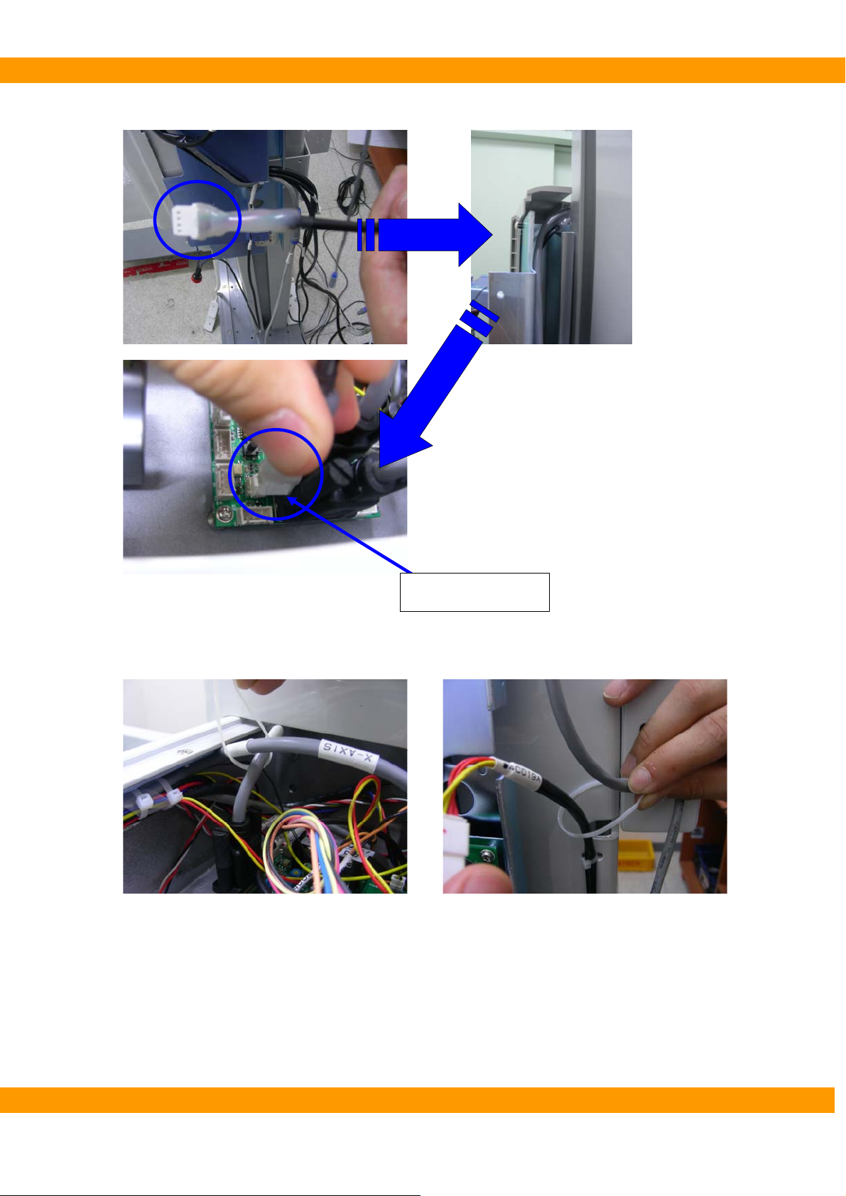
④ Connect the serial cables of Cephalo unit to X-Axis MCU.
1
4
Serial cable of Cephalo unit
VA TECH Co., Ltd. 32
PaX-400C Installation Manual
⑤ Connect RS232 cable (serial cable) to X-Axis MCU.
⑥ Arrange the cables.
RS232 (Serial cable)
VA TECH Co., Ltd. 33

PaX-400C Installation Manual
⑦ Assemble Wall-bracket as the picture below. Insert 2 bolts, 2 spring washers and 2 nuts.
⑧ Attach Wall-bracket on Column. Insert 2 spring-washers and 2 nuts.
⑨ Screw Wall bracket into the wall.
VA TECH Co., Ltd. 34

PaX-400C Installation Manual
⑩ Remove the bolt fixing Rotating unit
You need to open Top Cover of Rotating unit for removing the Bolt.
The bolt fixing Rotating Unit
VA TECH Co., Ltd. 35
PaX-400C Installation Manual
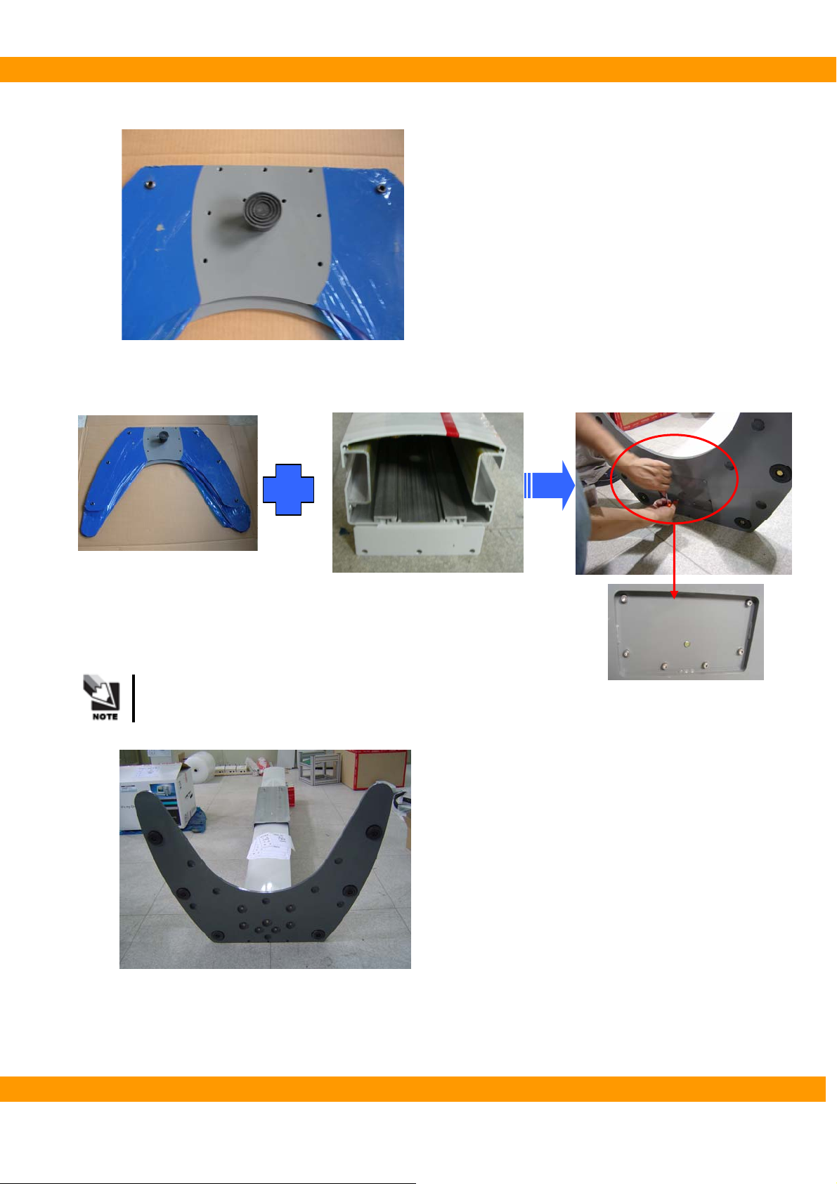
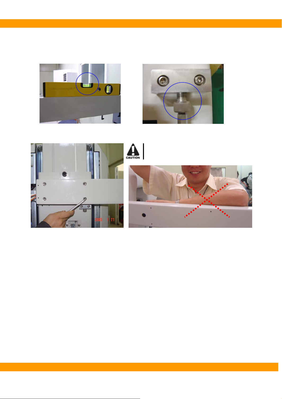
3.1.6. Others
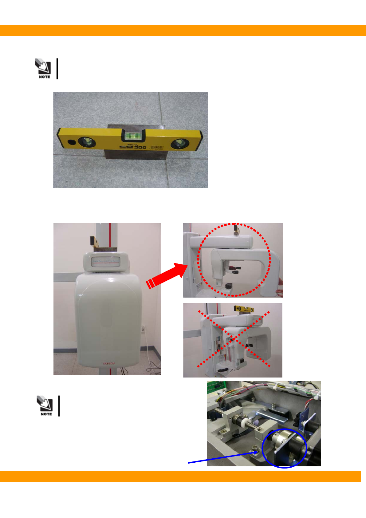
Use a leveler and a brick (plane and square) with the perfect balance in any part.
● The balance of the system
① Put Rotating unit as the pictures below.
When you put Rotating unit as above, you
should turn the coupler (see the right
picture) manually not to scratch the case
by Head rest.
VA TECH Co., Ltd. 36
Coupler

PaX-400C Installation Manual
② Put a leveler on Rotating unit and make a balance by screwing or unscrewing bolt ①
[Left and Right].
Do not put the leveler directly on Vertical unit
cover. Put a brick on top of the unit first and then
place the measurer on it.
③ Put the leveler on Rotating unit and make a balance by screwing or unscrewing bolt ② [Front
and Back].
Adjust the both right and left side.
② ②
① ①
② ②
② ②
① ①
② ②
VA TECH Co., Ltd. 37
PaX-400C Installation Manual
●The balance of Cephalo unit
① Put the leveler on Cephalo unit
② Adjust B[bolt], Checking A
A
③ Fix Cephalo unit to Column firmly by tightening 4 bolts.
Never lean on Cephalo unit while making
the balance.
B
VA TECH Co., Ltd. 38

PaX-400C Installation Manual
● Covering Rotating Unit
① Fix 2 Upper covers [large and small one] on the top of Rotating unit.
-. Upper cover (Small(A)): Put 5 Speed nuts on each projection and insert 5 screw bolts [M4*12] (see
bolt bag No.5) into rotating unit.
-. Upper cove (Large(B)): Insert 6 bolts [M4*12] (see bolt bag No.6) into Rotating unit.
A
B
③ Fix the lower cover to the bottom of Rotating unit. Insert 6 bolts (see bolt bag No.7) into Rotating
unit.
A Part (M4*10)
B Part (M4*16)
VA TECH Co., Ltd. 39

PaX-400C Installation Manual
● Covering Base Arm
① Assemble Level foot
② Install Base Arm to Base. Insert 3 bolts [M8*15] (refer to the bolt table on page 17, bolt No.9)
through Base arm into Base.
-. Unscrew 3 bolts [M8*15] on A part.
-. Attach Base arm to a base. And screw 3 bolts [M8*15] to fix Base arm on A part.
-. Screw 2 bolts [M6*40] to fix Base arm on B part.
A Part[M8*15]
● Up-down switch and Exposure switch
① Connect Up-down switch to Power case in A position.
② Connect Exposure switch to Connector in B position.
B Part[M6*40]
A B
VA TECH Co., Ltd. 40

PaX-400C Installation Manual
● Remove the Wrench bolt on the back of column.
● Checking power
Check Main Power with multi-meter/multi-tester.
Check whether your voltage range meets PaX-400C voltage AC
110/230V ±10% or not.
VA TECH Co., Ltd. 41

PaX-400C Installation Manual
● Changing power voltage from 220V to 110V
Open the right side door of the system.①
-. To open the right side door, remove the ‘L’ plate.
Change the plug from 220V to 110V.②
VA TECH Co., Ltd. 42

PaX-400C Installation Manual
4
Chapter 4 Computer setting
This chapter describes how to set a computer in detail
VA TECH Co., Ltd. 43

PaX-400C Installation Manual
4. Setting PC
4.1. Installing LAN card and Serial card
PC for PaX-400C should have at least 3 unoccupied PC slots
4.1.1. LAN card Installation
Should use the LAN card VATECH provides (Realtek RTL 8139 Family PCI).
Otherwise, we can not guarantee correct image processing.
● Installation
4.1.2. Serial card installation
Should use the Serial card VATECH provides.
Otherwise, we can not guarantee correct communication with PaX-P&P.
● Installation
VA TECH Co., Ltd. 44

PaX-400C Installation Manual
4.2. Connecting LAN cable and Serial cable
Connect cables firmly
4.2.1. LAN cable
4.2.2. Serial cable
VA TECH Co., Ltd. 45

PaX-400C Installation Manual
4.3. Driver setting
4.3.1. LAN card
① Driver will be installed automatically after turning on PC
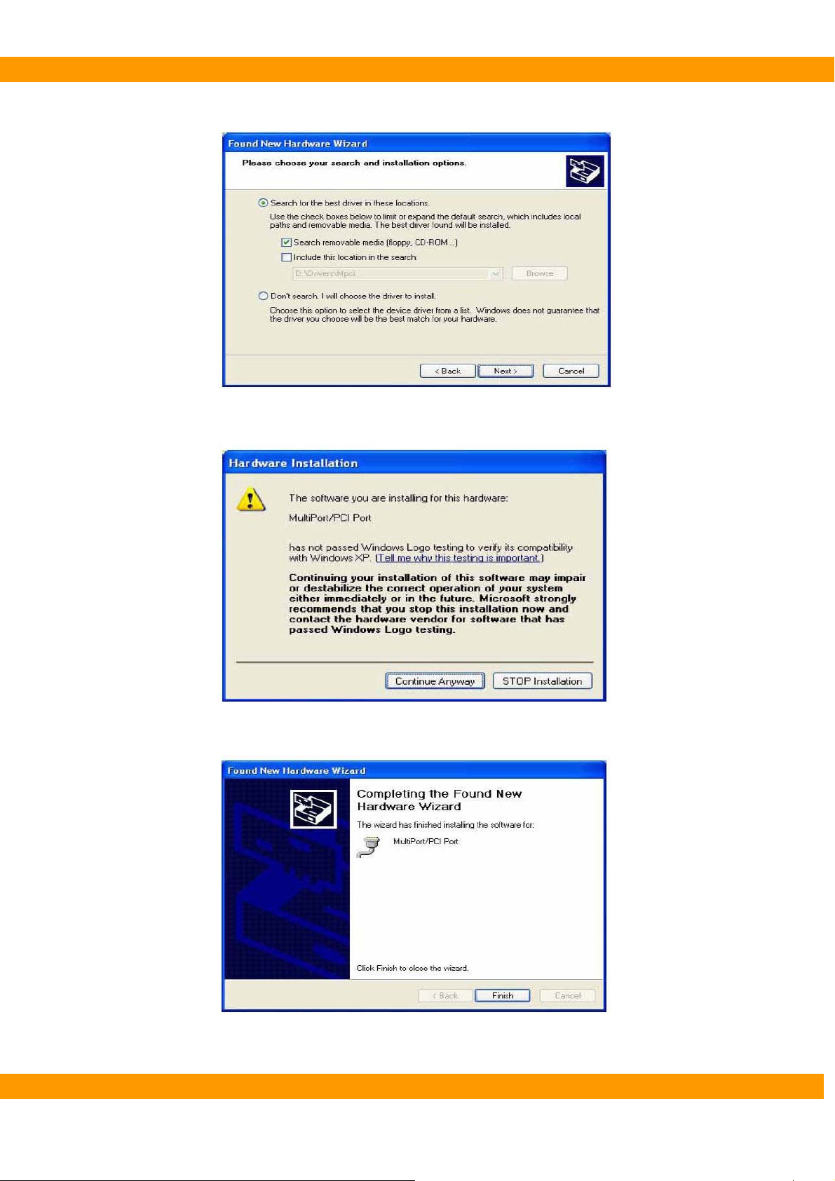
4.3.2. Serial card
① Turn on the PC
② Start windows XP.
③ New hardware is detected autometically.
④ Select ‘Install from a list or specific location’ and press ‘Next’ button.
⑤ Insert the provided MultiPort/PCI Installation disk into the CD-Rom drive.
⑥ Select ‘Search removable media (floppy, CD-ROM…)’ and press ‘Next’ button.
VA TECH Co., Ltd. 46

PaX-400C Installation Manual
⑦ Press ‘Continue Anyway’ button.
⑧ Press ‘Finish’ button.
⑨ Select ‘Install from a list or specific location’ and press ‘Next’ button.
VA TECH Co., Ltd. 47
PaX-400C Installation Manual
⑩ Select ‘Search removable media (floppy, CD-ROM…)’ and press ‘Next’ button.
⑪ Press ‘Continue Anyway’ button.
⑫ Press ‘Finish’ button.
VA TECH Co., Ltd. 48

PaX-400C Installation Manual
⑬ After installation, check whether the serial card is installed well or not.
→ [Setting]→[Control Panel]→[System]→[HardWare]→[Device Manager].
VA TECH Co., Ltd. 49

PaX-400C Installation Manual
4.4. Software installation
4.4.1. EasyDent V4
① Insert installation CD for “EasyDent V4” to CD-ROM/CD-RW.
When you install EasyDent V4, you should check whether the S/N of installation
CD and PaX-400C is the same or not.
InstallShield wizard ② will be started automatically on the computer.
③ Click “EasyDent V4” to install to the computer.
Click
VA TECH Co., Ltd. 50

PaX-400C Installation Manual
④ InstallShield will prepare for the installation of EasyDent V4.
Install⑤ Shield for EasyDent V4 will be started automatically. Click ‘Next’.
VA TECH Co., Ltd. 51

PaX-400C Installation Manual
⑥ Select ‘I accept the terms of the license agreement’ to install EasyDent V4 and click ‘Next’.
⑦ Select all the features (EasyDent4.0 Viewer, EzPaX Viewer, EzX Viewer, EzCam Viewer,
FileServer and DBServer) and click ‘Next’.
VA TECH Co., Ltd. 52

PaX-400C Installation Manual
⑧ Installation is started.
⑨ Installation of SQL server will be started automatically.
VA TECH Co., Ltd. 53
PaX-400C Installation Manual
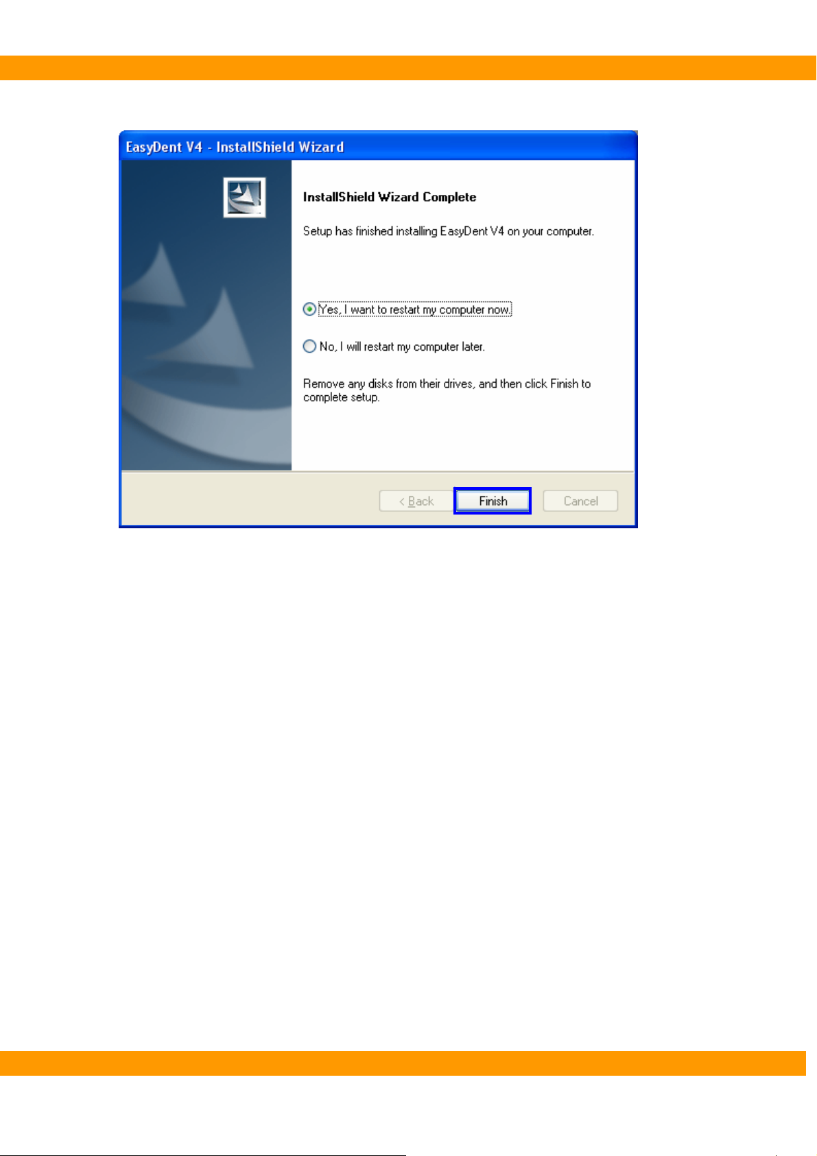
⑩ Click ‘Finish’ to finish installation of EasyDent V4.
VA TECH Co., Ltd. 54
PaX-400C Installation Manual
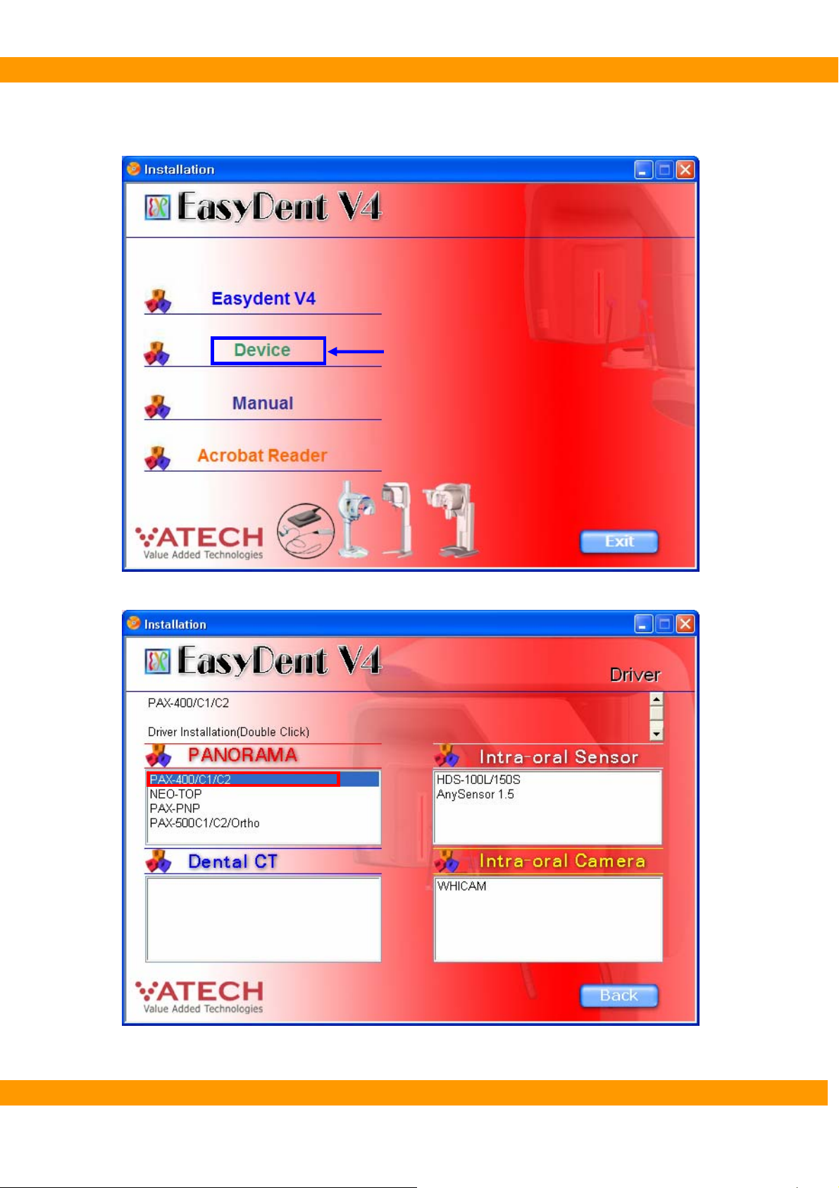
4.4.2. Device
① Click ‘Device’ to install.
Click
Click ② ‘PaX-400/C1/C2’ to install.
VA TECH Co., Ltd. 55

PaX-400C Installation Manual
4.4.3. Manual
C① lick ‘Manual’ to install.
Click
② Click (double click) the manual you want to install.
VA TECH Co., Ltd. 56
PaX-400C Installation Manual
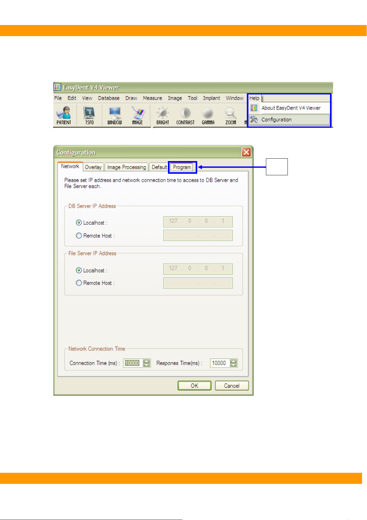
4.4.4. Set the device on EasyDent V4
① Run EasyDent V4.
Choose ‘Help => Configuration’ menu o② n menu bar.
③ Go to ‘Program’ tab when you see ‘Configuration’ window.
Click
VA TECH Co., Ltd. 57

PaX-400C Installation Manual
④ Select ‘Select capture mode for panorama’.
VA TECH Co., Ltd. 58

PaX-400C Installation Manual
⑤ Select ‘PaX-400 (Series)’ for ‘Mode 1’.
VA TECH Co., Ltd. 59

PaX-400C Installation Manual
⑥ Select the type what you use for ‘Mode 2’.
VA TECH Co., Ltd. 60

PaX-400C Installation Manual
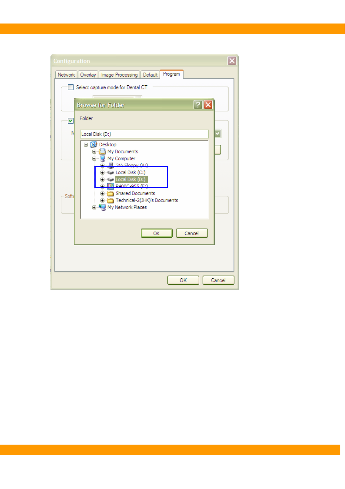
⑦ Set the path for the capturing program.
Click
VA TECH Co., Ltd. 61
PaX-400C Installation Manual
⑧ Double-click the drive where the capturing program is istalled.
VA TECH Co., Ltd. 62

PaX-400C Installation Manual
⑨ Choose ‘PaX-400’ folder. And then click ‘OK’.
VA TECH Co., Ltd. 63

PaX-400C Installation Manual
⑩ Click ‘OK’ after completing the setting of program on Configuration windo.
VA TECH Co., Ltd. 64

PaX-400C Installation Manual
4.5. IP setting
4.5.1. Setting IP address
Rename as Pano/Ceph.①
-. My Network Palace → Properties → Rename.
Please rename as Ceph as the same way above
Set IP addresses② (Pano:192.168.1.88/Ceph:192.168.1.87) and Subnet mask(255.255.255.0)
-. Properties → Internet Protocol(TCP/IP) → Use the following IP address.
Click all
The procedure for Ceph is the same as Pano.
VA TECH Co., Ltd. 65

PaX-400C Installation Manual
[The IP address for Pano]
[The IP address for Ceph]
VA TECH Co., Ltd. 66
PaX-400C Installation Manual
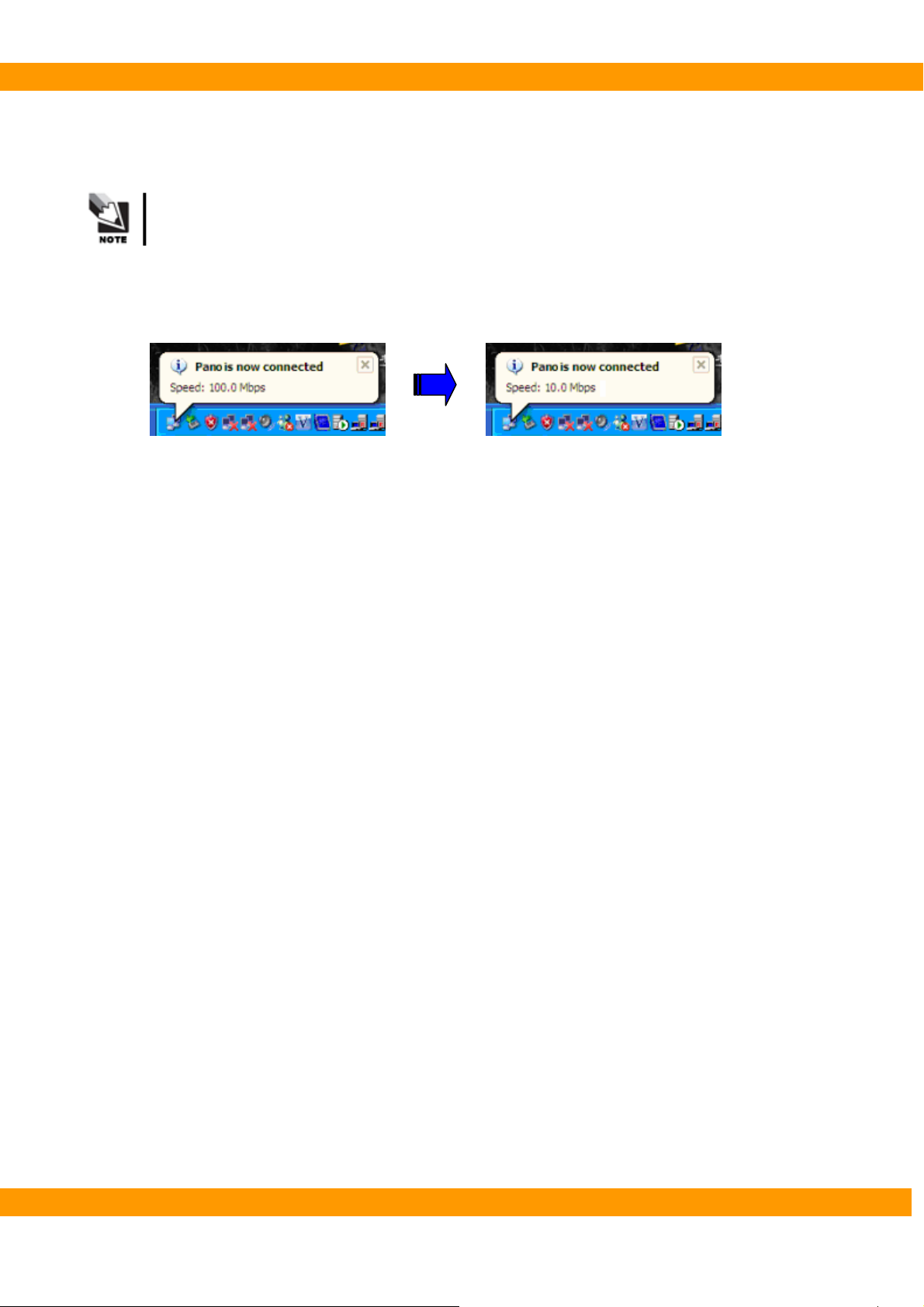
4.5.2. Checking connection with PaX-400C
Turn on PaX① -400C
The speed of Network will be changed from 100.0Mbps to 10.0Mbps after turning on
PaX-400C.
-. Check Network speed on the task bar
→ Speed: 100.0Mps -> Speed: 10.0Mps
VA TECH Co., Ltd. 67

PaX-400C Installation Manual
4.6. HyperTerminal setting
4.6.1. Setting HyperTerminal
① Select HyperTerminal
② Type in any name you want and Select Icon. ③ Connect using: COM3
VA TECH Co., Ltd. 68

PaX-400C Installation Manual
④ Bits per second: 19200 ⑤ Properties
Flow control: None
⑥ Setting -> ASCll Setup -> Settings
VA TECH Co., Ltd. 69

PaX-400C Installation Manual
4.6.2. Checking connection with PaX-400C
Run Hyper① -Terminal.
Turn on PaX② -400C.
The information of PaX-400C will be listed up after turning on PaX-400C.
VA TECH Co., Ltd. 70

PaX-400C Installation Manual
5
Chapter 5 Testing image
This chapter describes how to capture image
VA TECH Co., Ltd. 71

PaX-400C Installation Manual
5. Testing image
5.1. The test using Hyper Terminal
5.1.1. Commands to test communication between PC and PaX-400C
① [pan]: If you type in this command word and the communication between the system and the
computer is working properly, you can see [pan] command feedback, and Rotating unit will
move to Panoramic mode.
② [cep]: If you type in this command word and the communication between the system and PC is
working properly, you can see [cep] command feedback, and Rotating unit will move to
Cephalometric mode.
If you do not get the results as above, please refer to Troubleshooting manual,
or contact VATECH.
VA TECH Co., Ltd. 72
PaX-400C Installation Manual
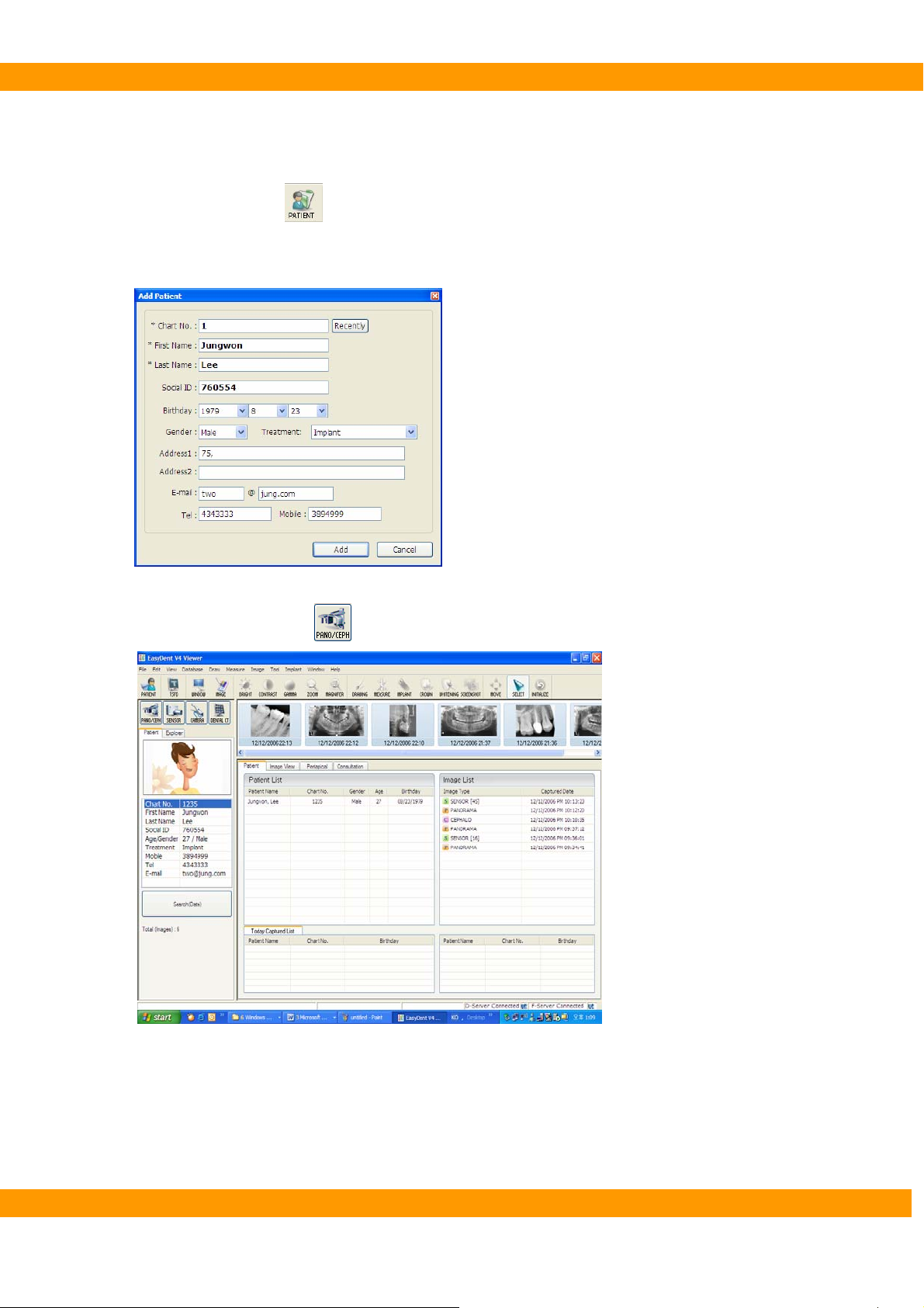
5.2. The Test using Capturing program
① Run EsayDent.
Click ‘Patient’ icon(②
Input the inf③ ormation of the patient.
Click ‘Add’ to complete ④ registration of the new patient.
Click ‘Pano/Ceph’ icon(⑤
) to register a new patient.
) to run capturing program.
VA TECH Co., Ltd. 73

PaX-400C Installation Manual
⑥ Click “CEPAHLO(
)” button to change mode to Cephalometric mode.
VA TECH Co., Ltd. 74

PaX-400C Installation Manual
⑦ Change the position of sensor from Panorama to Cephalo.
⑧ Check whether capturing mode is changed automatically or not.
If you do not get the results as above, please refer to Troubleshooting Manual,
or contact VATECH.
VA TECH Co., Ltd. 75

PaX-400C Installation Manual
5.3. Capturing Image (Final test)
① Run EasyDent.
② Choose a patient and call capturing program.
③ Choose capturing mode and position the patient.
④ Take panoramic and cephalometric images.
[Normal panoramic image]
[Normal cephalometric image]
If you do not get the results as above, please refer to the Troubleshooting Manual,
or contact VATECH.
VA TECH Co., Ltd. 76

PaX-400C Installation Manual
6. Warranty
VATECH hereby warrants free defects in this product and reliable quality within the warranty.
If any abnormality is found within the period of warranty, VATECH provides free charged repair service or
exchanges with a new part according to the kinds of cases.
Customers should pay for the costs of packing and transportation of a defective part to VATECH’s service
center of the local agency, and the expenses should be paid in advance by customers.
This guarantee doesn’t cover any malfunction or breakage occurred by misuse of customers. VATECH is
not responsible for services to below listed cases.
z Any breakage occurred during installation, repair, or manipulation by any one who is not VATECH’s
authorized personnel.
z Any breakage by neglecting of customer or by using with incompatible system.
z Any breakage or malfunctions caused by applying other brand assemblies.
VATECH’s obligation under this warranty is limited to repair and exchange products. With the exception
of factors stated in this warranty, this warranty will be not cover any direct, indirect, particular, or
accidental damages regardless of announcing possibility of critical results to customers in advance.
VA TECH Co., Ltd. 77

PaX-400C Installation Manual
VATECH Co., Ltd.
75-11 Seogu-ri, Dongtan-myeon, Hwaseong-si, Gyeonggi-do,
445-811 Republic of Korea
Tel : +82 31 379 9554
Fax: +82 31 377 1882
URL:
HTUhttp://www.vatech.co.krUTH
VA TECH Co., Ltd. 78
 Loading...