


EzSensor
User Manual

Attention
For improvement of product performance, supplementation, or follow-up of information, the contents of this
manual are subject to change without prior notice.
Please note that our company will have no responsibility for accidental damage nor be obligated to perform
warranty service for any damage to equipment due to user error, which is a result to properly follow the
contents of this manual.. Become familiar with the safety precautions and usage procedures for this product.
Note that the product may slightly differ from the contents of this manual depending on individual product
specifications.
The following symbols are used throughout this manual to provide effective use of this product
Indicates useful information and tips on how to use our software and
product.
Indicates important instructions. If not observed, malfunction or damage to
the system or other property may occur.
Indicates warnings and instructions for safety. If not adhered, serious risks
and injury may be caused to the patient and the operator.
1

Safety Procedures
The device must be installed and used in accordance with the safety regulations and instructions supplied
in this user manual for the purposes and applications which it is intended for.
Before each usage, check the outer surface of the EzSensor for any signs of physical damage or defect.
The surface of the EzSensor should have a smooth finish, with no evidence of chipping or damage.Otherwise,
contact your local distributor of VATECH & E-WOO products for further instructions on what to do.
To ensure correct usage of the EzSensor device in a clinical environment, for which intended purposes
correspond to its design and application, only dentists or their designated operators are authorized to
operate this system.
Modifications and/or additions to the device must be done exclusively by VATECH & E-WOO personnel or
by parties expressly authorized for the purpose by VATECH & E-WOO. Any modifications or additions must
always comply with the standards and generally recognized rules of good workmanship.
It is the user’s responsibility to ensure compliance with all local safety regulations in effect in the
state/country of installation.
Electrical safety
The covers of the device may be removed only by qualified and authorized technical personnel.
This device can only be used in rooms or areas which comply with all laws and regulations applicable to
electrical safety in the medical premises, such as CEI standards for the use of an additional ground terminal
for equipotential connections. This device must always be disconnected from the power supply before
cleaning or disinfecting.
Water and other liquids must not be permitted to penetrate inside the device, where they could cause short
circuit or corrosion. No protection is supplied against liquid penetration.
Explosion safety
This device is not recommended to be used in the presence of flammable gases or vapours. Some
disinfectants evaporate and form explosive or flammable mixtures. If disinfectants of this kind are used, it is
important to let the vapours disperse before using the device again.
For improvement of product performance, supplementation, or follow-up of information; the contents of this
manual are subject to change without separate prior notice.
2

Symbols
Symbols Descriptions
Item Symbol
1
2
3
4
Label Location
Description
Authorized representative in the European Community.
Type B applied
Indicates to the user to check the accompanying documents (this User
Guide) for more information about EzSensor.
Handle with care
The E-WOO TECHNOLOGY logo and the following label can be found on the EzSensor device.
• Medical Image Processing Unit
• Model : EzSensor
• SN : EZS-00000000 Date :

Contents
Contents
1. INTRODUCTION ......................................................................................................5
1.1. System Description ....................................................................................................... ............................... ..................................................5
1.2. System Components ................................................................................................................... ............................................7
1.3. Cone indicator (Optional) ............................................................................................................. .......................................10
2. HARDWARE INSTALLATION .............................................................................11
2.1. General Information ............................................................................................................. .................................................11
2.2. Specifications
.................................................................................................................... .......................................................11
2.3. Cable Connection & Driver Installation
...................................................................................... ....................................14
2.4. Installation of the EzSensor Holder ...........................................................................................................................................................19
3. SOFTWARE SETUP AND USAGE .......................................................... .........................20
3.1. Installation of EasyDent V4
................................................................................................................... .............................20
3.2. Image Acquisition with EzSensor ..................................................................................................................... .................25
3.3. Running the EasyDent V4 ............................................................................................................. .......................................26
4. MAINTENANCE .......................................................................................................35
4.1. Visual Inspection ..................................................................................................................................... ...............................35
4.2. Periodic Maintenance .............................................................................................................................................................35
4.3. Cleaning .................................................................................................................................................... .................................35
5. WARRANTY ........................................................................................................................36
APPENDIX ....................................................................................................................37
1. LED Indicators .....................................................................................................................................................................................................37
2. X-ray Exposure Guid
................................................................................................................................. ...............................38
3. Error Code
.....................................................................................................................................................................................42
4. Troubleshooting
...........................................................................................................................................................................45
4

1. Introduction
1. Introduction
1.1. System Description
EzSensor is a modern digital imaging solution for intraoral dental radiography. Its advanced CMOS
technology provides excellent image quality. For patient comfort, the EzSensor’s ergonomic design is
based on human intraoral anatomy.
EzSensor is a digital X-ray imaging system designed specifically for dental radiography within the oral cavity.
The system captures X-ray images and makes them available for display and storage across your network
of computers.
EzSensor is connected by a ‘USB A-A’ cable (supplied separately) to a compatible Console PC. The
Console PC runs Windows XP or Windows Vista and also provides power for the device.
Support for the EzSensor is provided by compatible software programs such as EasyDent V4. For other
custom applications, a programmer’s guide is available.
The EzSensor includes a detachable holder that can be mounted to a wall or other stable surface.
EzSensor is available in two sizes(1.5 and 1.0). Size 1.0 is suitable for children, while size 1.5 is appropriate
for adult patients.
● Excellent image quality based on advanced CMOS technology
● Optimized sensor shape for human oral structure
● Low-dose performance
● Easy-to-use USB 2.0 interface
5

1. Introduction
< Table 1. Specifications >
Parameter
Detector Structure
Dimension(W x L x T)
Pixel Pitch
Active Pixel Array
Dynamic Range
Signal to Noise Ratio
USB Cable length between Controller and
PC
6
Description
Low Noise Hybrid CMOS
1.14 x 1.52 x 0.19 inch
(29.2 x 38.7 x 4.9 mm)
0.035 mm
686 x 944 pixels
(24.01 x 33.04 mm)
4096
>37dB
3 m

1. Introduction
1.2. System Components
The EzSensor device installer should check the following items listed in the table below before system
installation. If the serial numbers of the individual parts do not match, do not install the system and contact
your local distributor or agent for support.
< Table 2. EzSensor Cable Connections >
No
1.
2.
Sensor Module
Control Box
Components
Remark
3.
4.
5.
6.
7.
8.
USB Cable (3M)
Holder for Control box
Holder for Sensor
EasyDent V4 Installation CD
Driver Installation CD
EzSensor Manual
USB 2.0 (Mandatory)
Document
1. Sensor Module
Consists of a special CMOS sensor specifically designed for use in radiography and enclosed in a
hermetically sealed ergonomic capsule. The sensitive surface of the sensor is covered with a thin
layer of scintillating phosphorous through which X-ray radiation is converted into light and then into
an electric charge.
7

1. Introduction
2. Control Box
Provides power for the sensor, timing and synchronization of sensor signals, signal pre-amplification,
analogue/digital signal conversion, USB port interface and optical insulation of all connections.
3. USB Cable(3M)
Used to transmit output signal from the control box to the computer.
4. Control Box Mount
Used to mount the control box at the preferred location.
5. Sensor Holder
Used to stow the sensor when not in use.
8

1. Introduction
6. EasyDent V4 Installation CD
7.DriverInstallationCD
9

1. Introduction
1.3. Cone indicator (Optional)
The cone indicator is an intraoral positioning device specifically designed to support and align the sensor
with the X-ray source when positioning along the upper or lower jaw.
Please refer to the appendix for more information. (Pages 46 ~ 48)
10

2. Hardware Installation
2. Hardware Installation
2.1. General Information
To operate the intraoral sensor, you need to install EasyDent V4 and the EzSensor driver.
2.2. Specifications
We cannot guarantee that EasyDent V4 will work properly with an
unregistered copy of Microsoft Windows. Therefore, you should use
registered, genuine version of Microsoft Windows.
2.2.1. PC Specifications
① Operating System
● Microsoft Windows XP Home Edition Version 2002 Service Pack 2 or above.
● Microsoft Windows Vista Home Edition or above.
② Hardware Requirements
● Main CPU: Intel Pentium IV 3.0 GHz
● Main Memory: 512 MB of RAM (DDR2)
● Video Memory: 64 MB
● HDD: 80 GB (larger size of HDD and SATA/7200 rpm are preferred)
● CD-ROM (prefer CD-RW)
● USB 2.0 (Mandatory)
● Network Card: 1 EA
● Monitor: Min. resolution: 1024*768
● Keyboard/Mouse
Turn off the Windows Firewall service for proper communication across the
network for the installed database and file servers.
If you need to install additional software on your computer, please install
only those that are internationally authorized. Take extra precaution when
installing any Active-X controls.
11

2. Hardware Installation
2.2.2. EzSensor Driver Setup
This step is necessary for the installation of EzSensor. Calibration data for the EzSensor will be installed
along with the Windows device driver.
Step 1
Insert the EzSensor Driver
Installation CD in the CD-ROM.
Setup should start automatically.
If it does not, click Start > Run
and type D:\EzSensor\setup.exe
Step 2
The install program for ‘E-Woo
Intraoral Detector Software’ will
appear. Click the ‘Next’ button.
12
2. Hardware Installation
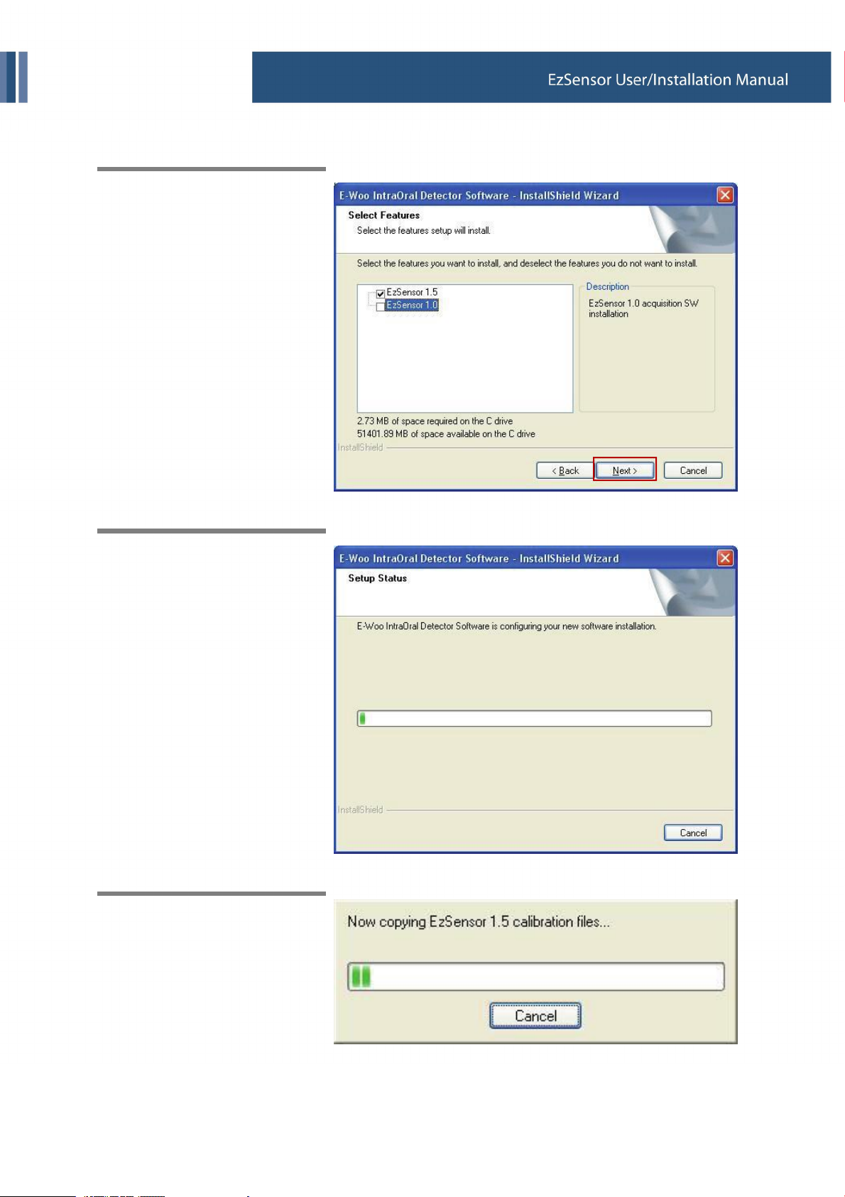
Step 3
Select the EzSensor feature that
you want to install. Check
‘EzSensor 1.5’ or ‘EzSensor 1.0’
and then click the ‘Next’ button.
Step 4
The Installshield Wizard will start
configuring the installation
parameters you have chosen.
Step 5
The InstallShield wizard will copy
the EzSensor calibration files to
your workstation(PC).
13

2. Hardware Installation
2.3. Cable Connection & Driver Installation
Do not connect the EzSensor and USB cable to your computer until you
have successfully installed the setup program.
Be sure to connect the EzSensor module to the control box before
connecting the USB cable to your computer.
Step 1
Connect the EzSensor Module to
the Control box.
Step 2
Connect the USB Cable to the
Control box.
14

2. Hardware Installation
Step 3
Connect the USB cable
connector to the USB 2.0 port on
the PC.
Step 4
After connecting the USB Cable
to the USB 2.0 port on the PC,
the ‘Found New Hardware
Wizard’ will appear.
If the ‘Found New Hardware
Wizard’ does not appear,
reconnect the USB Cable
connector to the PC.
Select ‘Install from a list or
specific location (Advanced)’, and
then click ‘Next’.
15

2. Hardware Installation
Step 5
Select ‘include this location in the
search’.
Click ‘Browse’, and then select
‘EzSensor100’ or ‘EzSensor150’
Folder.
And then click ‘Next’ button.
Step 6
If the ‘Hardware Installation’
window appears, click
‘Continue Anyway’
16

2. Hardware Installation
Step 7
Driver Installation has been
completed successfully.
Click the ‘Finish’ button.
Step 8
Confirmation of Driver installation at the Device Manager.
Method of Confirmation : Settings → Control Panel → System → Hardware → Device manager
Select the ‘Vatech HDS Driver’, located under Imaging Devices. You should see the message, “This
device is working properly”.
17

2. Hardware Installation
18
2. Hardware Installation
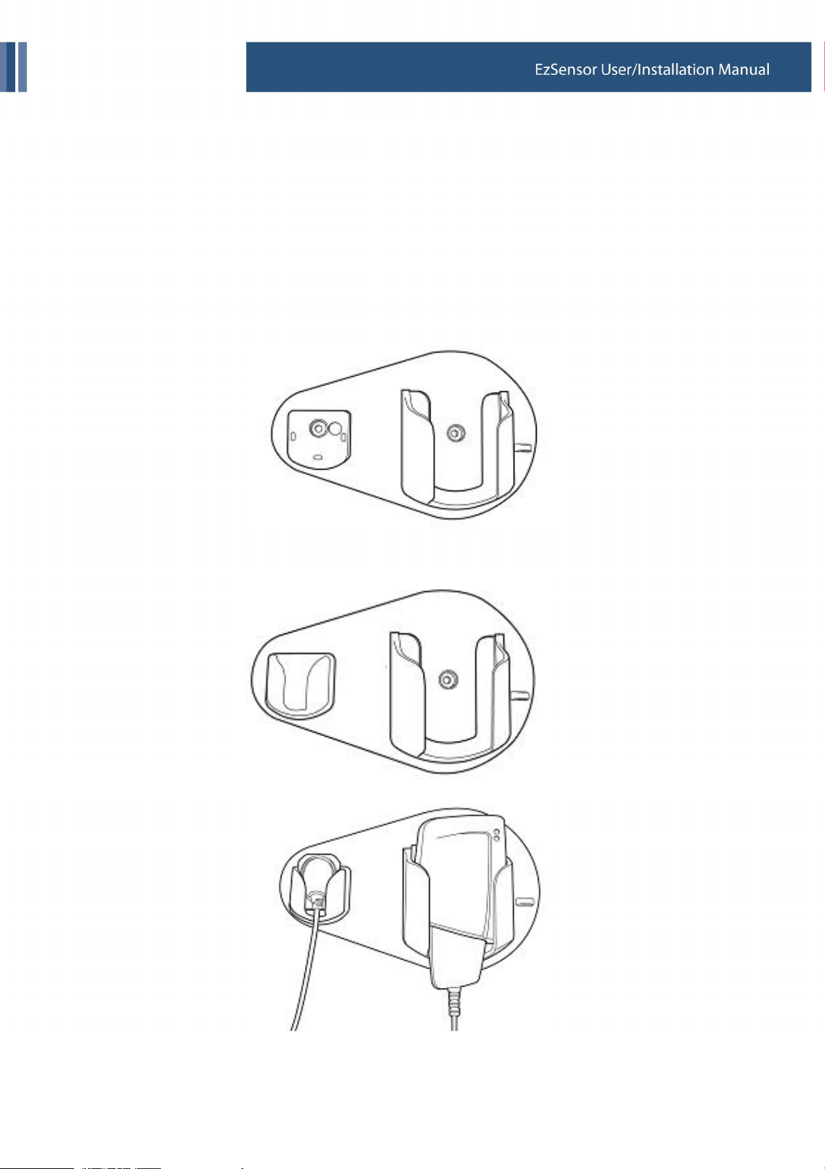
2.4. Installation of the EzSensor Holder
The EzSensor holder is used for mounting the EzSensor to the wall when it is not in use.
When choosing where to install the EzSensor, locate an area that offers easy access and visibility during
patient examination.
① Position the holder on a stable, flat surface. Using the holes at the back of the holder as guides,
fasten the holder securely to the wall using 2 dry wall screws (included).
② Remove the tape from the backside of the silicon holder. Attach the silicon holder to the sensor holder.
19

3. Software Setup and Usage
3. Software Setup and Usage
3.1. Installation of EasyDent V4
Step 1
Insert the EasyDent installation
CD in the CD-ROM drive.
Setup should start automatically.
If it does not, click Start → Run,
and type
D:\EasyDentV4\setup.exe.
Press ‘Enter’.
Step 2
Select the language you want to
install and then click ‘Next’.
20

3. Software Setup and Usage
Step 3
Preparing the installation.
Step 4
The ‘EasyDent V4 InstallShield
Wizard’ will appear. Click ‘Next’
button.
21
3. Software Setup and Usage
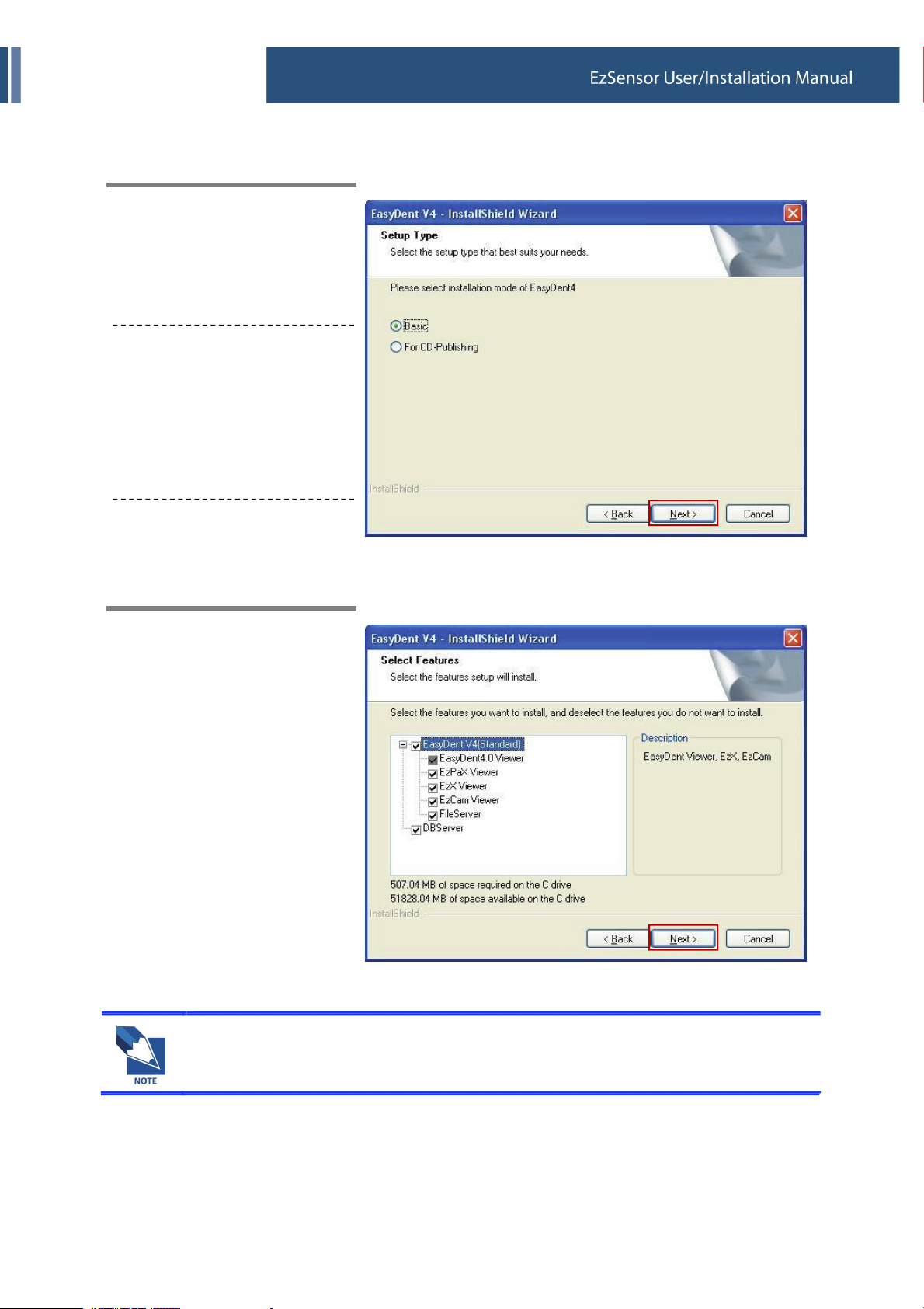
Step 5
Select the setup type that best
suits your needs.
Click ‘Next’ button.
Basic : Installs the basic version
of Easydent V4
CD-Publishing : Installs the
basic version of EasyDent V4
along with CD-Publishing
capabilities. (optional)
Step 6
Select the features that you want
to install. Click ‘Next’ button.
For the EasyDent server, select all items. For PC being used for viewer :
Select only the items except for DB & File servers.
22
3. Software Setup and Usage
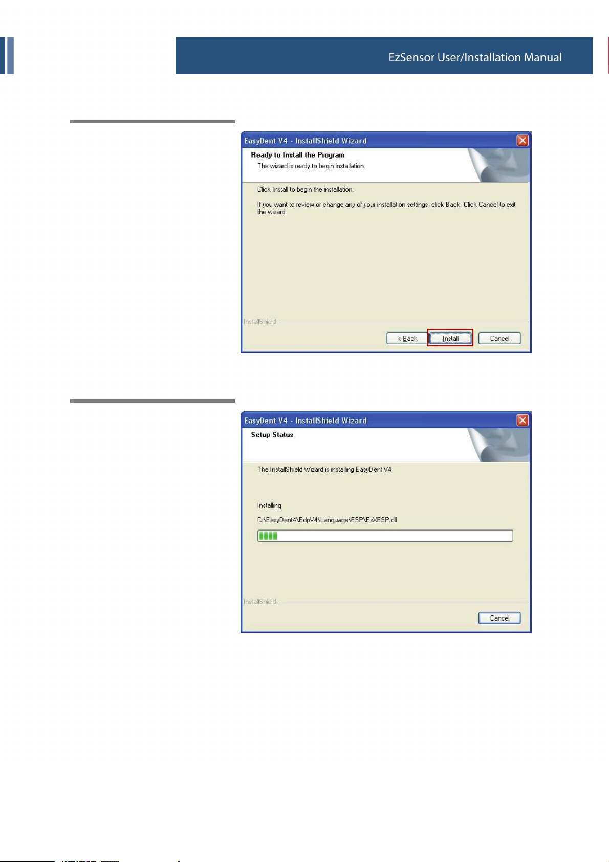
Step 7
Now you are ready to install.
If you would like review any of
your installation settings, click
‘Back’, To proceed with the
installation, click ‘Install’.
Click ‘Cancel’ to exit the wizard.
Step 8
Installing EasyDent V4.
23

3. Software Setup and Usage
Step 9
MSDE(Microsoft SQL server
Desktop Engine) is installed
automatically.
Step 10
Choose ‘No, I will restart my
computer later’, and then click
‘Finish’.
24

3. Software Setup and Usage
3.2. Image Acquisition with EzSensor
① Turn on the computer that has the EzSensor software installed (EasyDent v4 – Refer to 3.2).
② Set the required X-ray parameters (exposure time, etc.) on the X-ray source.
Put a new disposable cover on the EzSensor.
③ Position the EzSensor at the appropriate area of the mouth
The sensor must be positioned with the flat side facing the X-ray source.
The use of a cone indicator is recommended to guarantee that the sensor is parallel to the tooth and
at the proper angle for exposure.
④ The use of the parallel technique with a cone indicator, if possible, is highly recommended.
⑤ After preparing the sensor for exposure in EasyDent v4, acquire an image by pressing the exposure
button for your X-ray source.
<Using the EzSensor with EXS intraoral X-ray> <Using the EzSensor with a Cone Indicator (optional)>
25

3. Software Setup and Usage
3.3. Running the EasyDent V4
3.3.1. Patient Registration
Step 1
Turn on the PC.
Run EasyDent V4. Click ‘Patient (
)’ icon to register a new patient.
26
3. Software Setup and Usage
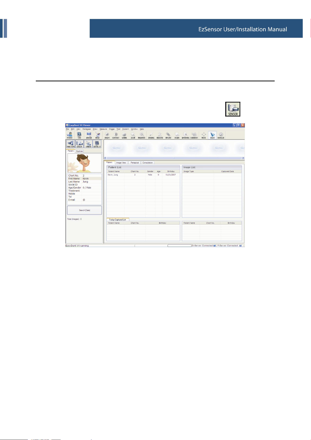
3.3.2. Normal Mode
Step 1
Start EasyDent by clicking the EasyDent V4 Viewer on the desktop.
Search and enter the appropriate patient information and then click the ‘Sensor(
27
)’ button.

3. Software Setup and Usage
Step 2
Select your capture device. Please click ‘EzSensor 1.5’ then choose the image type.
① HC (Default) : High Contrast
② MC : Middle Contrast
③ LC : Low Contrast
④ HC_N : High Contrast (New Image processing)
⑤ MC_N : Middle Contrast (New Image processing)
⑥ LC_N : Low Contrast (New Image processing)
⑦ NI : Normal Image
If the capture device is not selected, you will get the following error message.
28
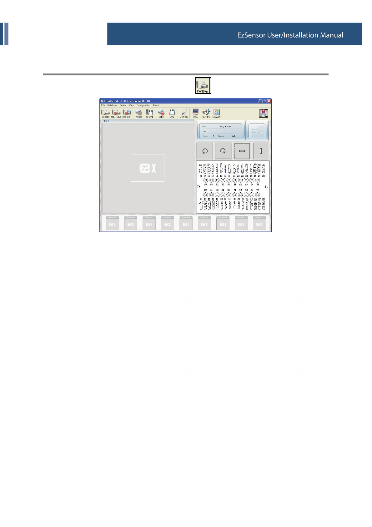
3. Software Setup and Usage
Step 3
Select the tooth position and then click the ‘Capture’(
29
) button.
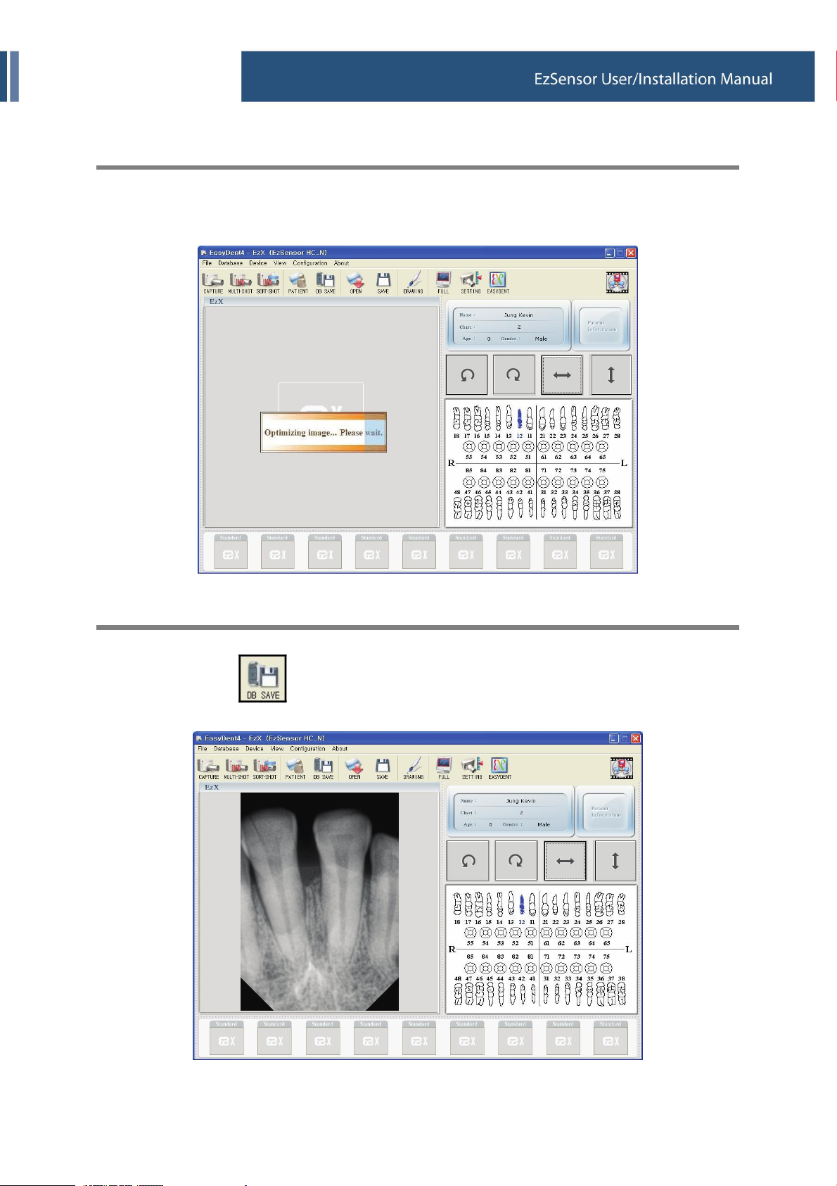
3. Software Setup and Usage
Step 4
Expose the X-ray after the “Please expose X-ray” message appears.
The message, “Optimizing Image… Please wait” appears momentarily while the image is being
optimized. The image will appear after optimization is complete.
Step 5
Click the ‘DB SAVE(
)’ button to save the image.
30

3. Software Setup and Usage
3.3.3. Multi-Shot
Step 1
Click the ‘MULTI-SHOT (
)’ button.
The system will get ready to acquire an X-ray image.
Step 2
Expose the X-ray after the “Press the X-ray (shot) button” message appears.
31

3. Software Setup and Usage
Step 3
The message, ‘Optimizing Image… Please wait’ will appear momentarily while the image is being
optimized. The image will appear after optimization is complete.
Step 4
Expose the X-ray again for a subsequent shot.
32
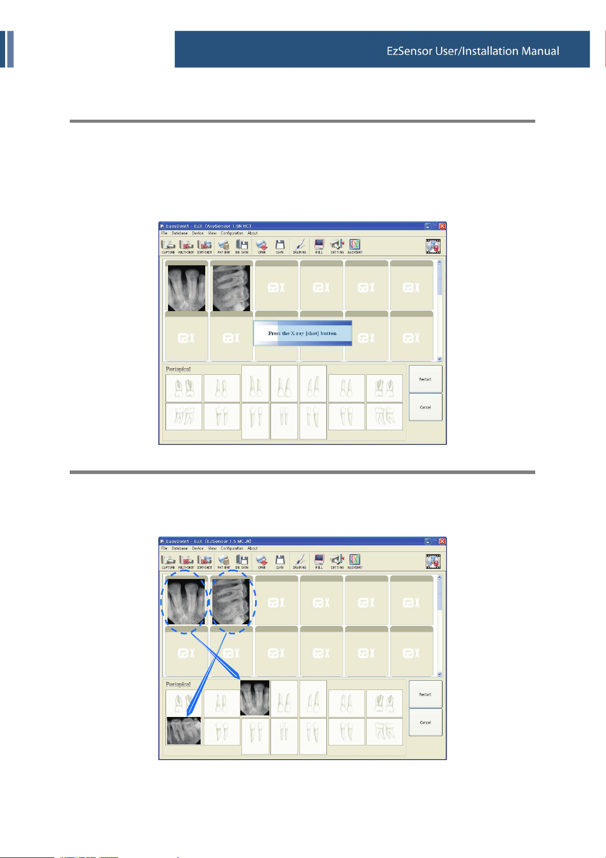
3. Software Setup and Usage
Step 5
If you want to acquire more images, continue to expose the x-ray when the ‘Press the X-ray (shot)
button’ message appears.
If you want to finish, click the ‘Finish’ button.
Step 6
Click and drag the image to its appropriate position.
33

3. Software Setup and Usage
Step 7
Click ‘DB SAVE (
Step 8
)’ to save the images.
Click the ‘MULTI-SHOT(
)’ button again to exit the Multi-shot Mode.
34

4. Maintenance
4. Maintenance
4.1. Visual Inspection
Like all electrical systems, EzSensor requires not only correct usage, but also visual inspection prior to
operation, Along with routine checks at regular intervals. These precautions will help ensure that the system
operates accurately, safely, and efficiently.
Before using, the operator should check the system for any signs of physical damage or defect. If
something is detected, contact your local distributor of VATECH & E-WOO products for further instructions
on what to do.
4.2. Periodic Maintenance
Periodic maintenance should be performed if needed, but at least once a month. It must consist of various
checks performed by the operator or by a qualified service technician.
● Check that all cables connected to the EzSensor are undamaged
● Check for external damage to the EzSensor that could compromise its ability to operate safely.
4.3. Cleaning
To clean the EzSensor, use either of the following solutions listed below and observe the noted precautions.
● Mild soap and water
● Isopropyl alcohol (70%)
Do not soak or immerse the system and be sure to dry it completely afterwards.
Clean the surface of the system by moistening it with a soft cotton swab dipped in either of the cleaning
solutions listed above. Gently wipe the surface from end-to-end in lines without applying pressure. Make
sure that the liquid will not penetrate the system through the USB cable or the sensor cable connectors.
After cleaning the surface of the EzSensor, use a clean lint-free cloth to dry the system, as needed, until the
surface is clean.
35

5. Warranty
5. Warranty
The EzSensorTMis warranted to be free from sensor defects in sensor and workmanship from the date of
installation for a period of 12 months.
In the event that the product is returned by the dealer or the end-user after the warranty has expired, we
reserve the right to collect a reasonable fee from the end user for services mutually agreed upon.
Any item returned to the factory, through an authorized dealer VATECH & E-WOO, will be repaired or
replaced at our option at no charge provided that our inspection indicates it to have been defective.
Dealer’s labor cost, shipping and handling charges are not covered by this warranty.
This warranty does not apply to damages due to shipping, misuse, or careless handling. Warranty is void if
the system is installed, repaired, or serviced by anyone other than authorized service personnel, as dictated
by VATECH & E-WOO.
36
Appendix
Appendix
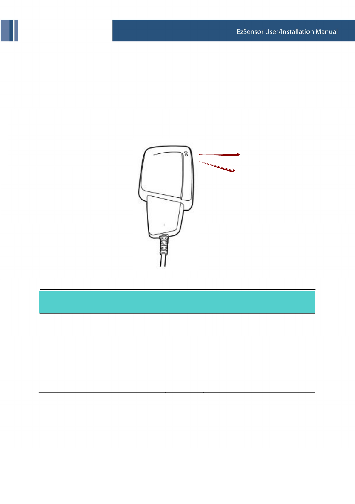
1. LED Indicators
The EzSensor Hardware Controller has two LED indicators that show its functional status.
The location of the LED lights is shown in the following illustration and described in Table 3.
LED 1
LED 2
< Table 3. Description of LED Indicators >
Operational State
LED State
LED 1 LED 2
Functional Status
Confirmation
Initial State
Standby
Trigger (X-ray On)
Data Transmission
with USB cable
Image acquisition
Green
Green
Orange
Green Orange
Green
Off
Green
Green
Off
37
USB Connection
Board On
X-ray On and Sensor Trigger On
Confirm data transmission
with sensor board
Completion of data transmission
with PC-board

Appendix
2. X-ray Exposure Guide
< Table 4. Detailed Exposure Guidance Table>
Ref.
Exposure condition Dose
Signal Level
60kvp
2mA
60kVp
6mA
65kVp
5mA
Patient
Cone to skin
Section
-
-
No
Filter
-
-
4mm
Al filter
--Adult
8cm
AnyRay
Adult
8cm
VX 70
Adult
8cm
ESX-
Series
Upper
Approximate Exposure Time
Upper
Lower
Jaw/
Anterior
Upper
Jaw/
Canine
Upper
Jaw/
Posterior
Lower
Jaw/
Anterior
Lower
Jaw/
Canine
Lower
Jaw/
Posterior
2800
2800
3200
2400
2400
2800
1800
1800
2100
1400
1400
1800
160 0.20 0.16 0.22
160 0.20 0.16 0.22
200 0.25 0.20 0.27
130 0.15 0.12 0.18
130 0.15 0.12 0.18
160 0.20 0.16 0.22
For larger body types : increase the source current by 25%
For children : reduce the source current by 20%
For edentulous patients : reduce the source current by 20%
38

Appendix
The X-ray dose required for image acquisition can vary depending on the X-
ray source and environmental circumstances. You must maintain the
exposure time and change the kVp and mA values according to the signal
level. In addition, if the X-ray source and the distance to the sensor were
changed during the initial installation, the distance (from cone to detector)
must be changed to the 80mm setting.
To reduce an initial measuring error, you should use a 4mm Al filter to
maintain a distance that is identical to the conditional circumstances of the
test.
The exposure time may vary depending on the age, gender and bone
density of the patient.
39

Appendix
How to optimize the exposure conditions?
Position the EzSensor and the X-ray source, as shown below. The distance between the cone and the
detector should be 80mm (8cm). Please align the X-ray source over the sensor.
1. Distance: 80mm(8cm) (from cone to detector)
2. Added filter: 4mm Al filter (or No filter )
3. Signal level: after calibration of image
Run program ‘_EzSensor150’ located in C:\EzSensor150
40
Appendix
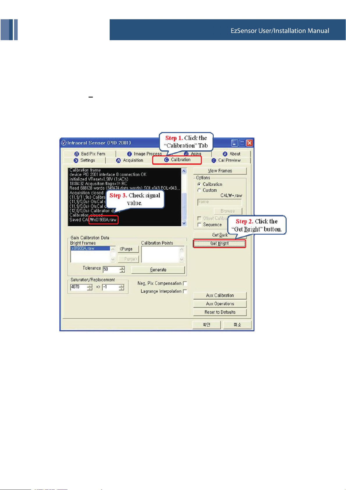
Follow the steps below:
[Step 1] Click the ‘Calibration’ tab.
[Step 2] Click the ‘Get Bright’ button for the exposure time.
; Refer to ‘Table 4. Detailed Exposure Guidance Table’.
[Step 3] Check the command window.
41

Appendix
3. Error Code
1. Code 0
● Message : USB device driver is not installed.
● Solution : Please install device driver again.
2. Code 1
● Message : USB driver can't detect connected sensor device. Check connection.
● Solution : Check and re-connect USB cable.
3. Code 2
● Message : USB device driver is not working properly.
● Solution : Re-install the driver.
4. Code 3
● Message : Capture program is already running.
● Solution : Please close other program.
5. Code 4
● Message : Detector's response time-out.
● Solution : Check and re-connect USB cable. Contact Customer Service.
6. Code 5
● Message : Data communication error.
● Solution : Re-connect USB cable.
7. Code 6
● Message : Data communication error.
● Solution : Re-connect USB cable.
8. Code 7
● Message : Canceled image capturing.
● Solution : User canceled image capture. Please try again.
42

Appendix
9. Code 8
● Message : Bad Pixel's map correction error.
● Solution : Restore the EzSensor’s calibration data from the installation CD or re-calibrate the sensor.
Contact Customer Service.
10. Code 9
● Message: Bad Pixel's map correction error.
● Solution: Restore the EzSensor’s calibration data from the installation CD or re-calibrate the sensor.
Contact Customer Service.
11. Code 10
● Message :. Can't find dark frame.
● Solution : Restore the EzSensor’s calibration data from the installation CD or re-calibrate the sensor.
Contact Customer Service
12. Code 11
● Message: Can't find bright frames for calibration
● Solution: User canceled image capture. Please try again.
13. Code 12
● Message: Canceled image capturing.
● Solution : User canceled image capture. Please try again.
14. Code 13
● Message: Wrong image processing parameters.
● Solution: Check X-ray source.
15. Code 14
● Message: Error in configuration file.
● Solution: Please re-instal acquisition software.
16. Code 15
● Message: Image process library was damaged.
● Solution: Please re-instal acquisition software.
43

Appendix
17. Code 16
● Message: Image process library was damaged.
● Solution: Please re-instal acquisition software.
18. Code 17
● Message : Can't load 'EzSensor150.dll'.
● Solution : Please re-install acquisition software.
19. Code 18
● Message : Requre 'EzSensor150.DLL' was damaged.
● Solution : Please re-install acquisition software.
20. Code 19
● Message : Canceled image processing.
● Solution : Please try again.
44

Appendix
4. Troubleshooting
In case you experience any problems regarding the EzSensor system during operation, please refer to the
troubleshooting table below for corrective actions. If the problem persists, please contact your local
distributor of VATECH & E-WOO products.
< Table 5. Troubleshooting Table >
Item
1
2
3
4
Description
LED 1 on the control box doesn’t illuminate
after installing the device.
LED 1 on the control box continuously
illuminates an ORANGE light during image.
acquisition
LED 2 on the control box continuously
illuminates a RED light during image
acquisition.
A ‘PID 2001 NO; interface #0 (Check
Connection)’ error message is displayed.
45
Corrective Action
Check that the USB cable is plugged in
correctly at the Control box and on the console
PC.
Check that the Sensor is properly connected.
Unplug the USB cable from the control box and
then reconnect it.
Unplug the USB cable from the control box and
then reconnect it.
Open the Windows Device Manager and check
that the device is installed correctly.
Alternately, try another USB port on your
computer.
Unplug the USB cable from the control box and
then reconnect it.
Open the Windows Device Manager and check
that the device is installed correctly.
Alternately, try another USB port on your
computer..
Appendix
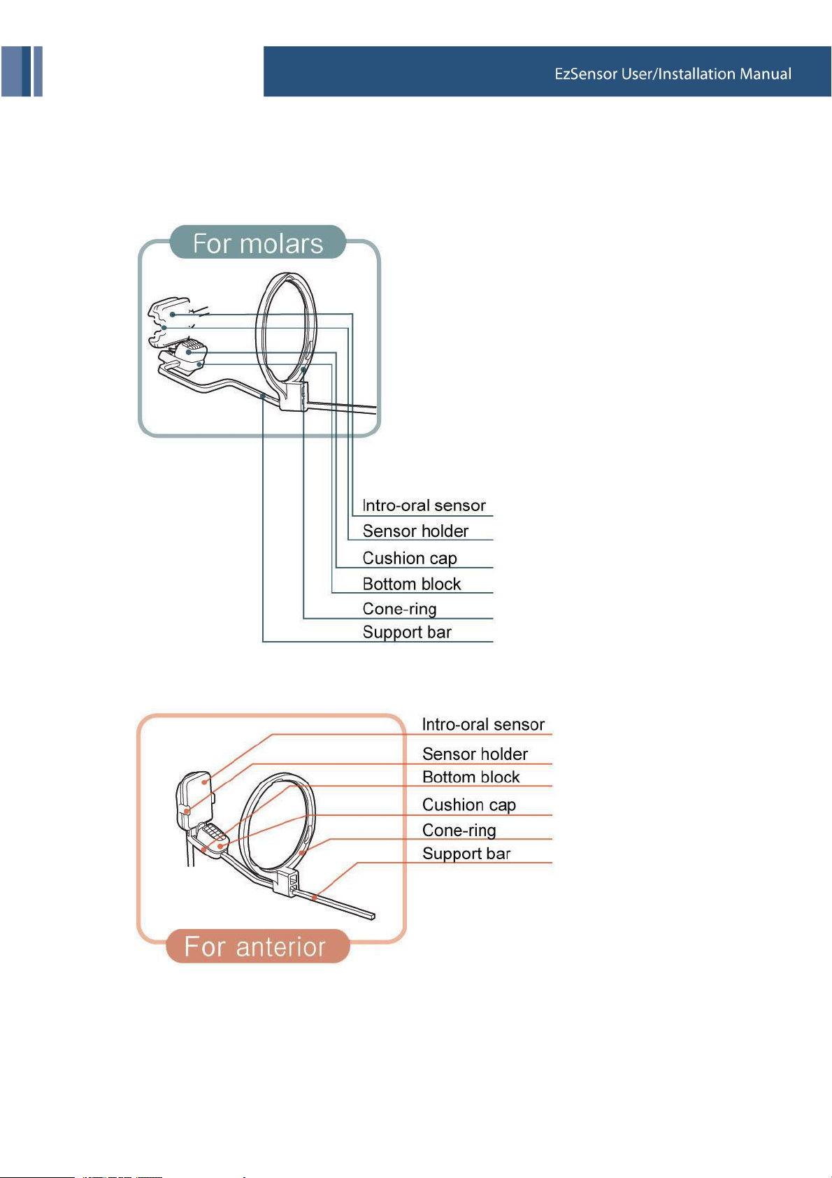
4.1. How to use the cone indicator
① Cone indicator for molars
② Cone Indicator for anterior
46

Appendix
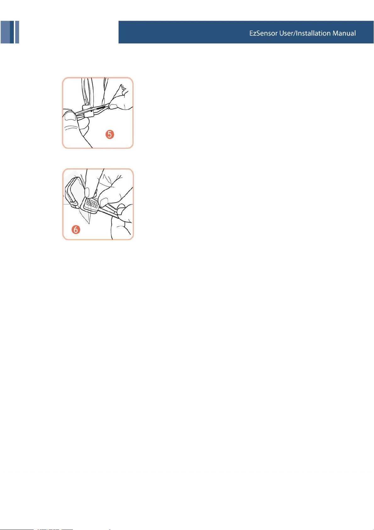
● Usage
① Insert the sensor into the disposal bag provided.
② Pass the sensor through the cone ring, into the sensor holder.
③ Fix the sensor firmly to the sensor holder.
④ Put the sensor cable in the cable-holder, located at the side of the bottom block.
47
Appendix
⑤ Fasten the sensor cable on the cone ring with the cable hook.
⑥ Put the cushion cap on the top of the bottom block.
48

 Loading...