

Page 1
Installation, Oper ating & Maintenance Instructions
Series 651 DN 320-400 (I.D. 12“ - 16”), Logic
VAT Vakuumventile AG, CH-9469 Haag, Switzerland
Tel +41 81 771 61 61 Fax +41 81 771 48 30 [email protected] www.vatvalve.com
267736ED
2008-02-26
1/53
Pendulum control & isolation valve
with extended control range
with Logic interface
This manual is valid for the valve ordering number(s):
651 . . - . . GC - . . . . (1 sensor input)
651 . . - . . GE - . . . . (2 sensor inputs)
651 . . - . . AC - . . . . (1 sensor input / ±15V SPS)
651 . . - . . AE - . . . . (2 sensor inputs / ±15V SPS)
651 . . - . . HC - . . . . (1 sensor input / PFO)
651 . . - . . HE - . . . . (2 sensor inputs / PFO)
651 . . - . . CC - . . . . (1 sensor input / ±15V SPS / PFO)
651 . . - . . CE - . . . . (2 sensor inputs / ±15V SPS / PFO)
SPS = Sensor Power Supply PFO = Power Failure Option
configured with firmware 651P.1E.05
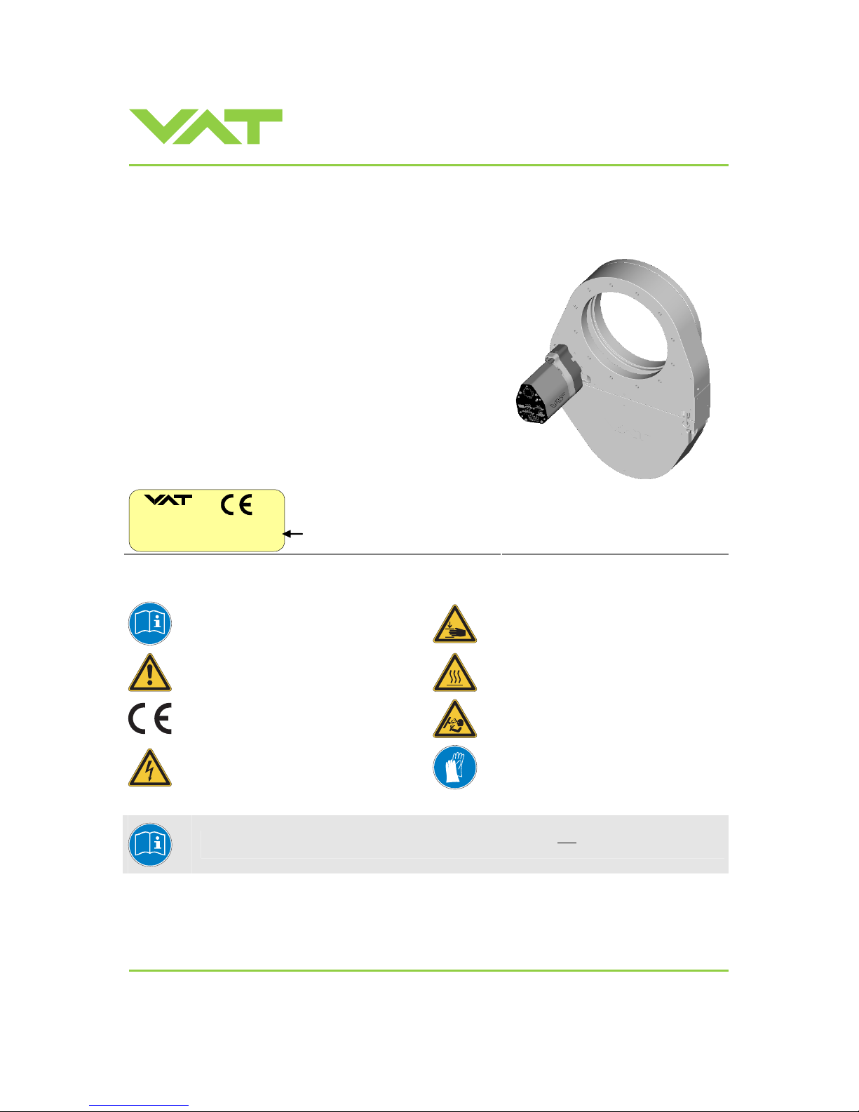
The fabrication number is indicated on each product as per the label
below (or similar):
made in Switzerland
Fabrication No.:
patented
. .
651 . . – . . . . – . . . . / . . . .
A –
. . . . . .
Fabrication num ber
sample picture
Explanation of symbols:
Read declaration carefully before you start any other
action!
Keep body parts and objects away from the valve
opening!
Attention!
Hot surfaces; do not touch!
Product is in conformity with EC guidelines,
if applicable!
Loaded springs and/or air cushions are potential
hazards!
Disconnect electrical power and com press ed air
lines. Do not touch parts under voltage!
Wear gloves!
Read these «Installation, Operating & Maintenance Instructions» and the enclosed «General
Safety Instructions» carefully before you start any other action!
Page 2

Installation, Oper ating & Maintenance Instructions
Series 651 DN 320-400 (I.D. 12“ - 16”), Logic
VAT Vakuumventile AG, CH-9469 Haag, Switzerland
Tel +41 81 771 61 61 Fax +41 81 771 48 30 [email protected] www.vatvalve.com
267736ED
2008-02-26
2/53
Contents:
1
Use o f pr o d uc t .......... .. ................ .. ................ ... ............... ... ................ .. ................ ..................................................... 3
1.1 Technical da ta ........................ .. ................ .. ................ .. ................ .. ................ ................ ................................. 3
2 Installation................................................................................................................................................................. 6
2.1 Unpacking........................................................................................................................................................ 6
2.2 Installati on in t o the s ys te m ............ ............... ... ............... ... ................ .. ................ ................ ............................ 6
2.3 Tightening torque............................................................................................................................................. 8
2.3.1 Mounting with centeri ng rings................. ..................... ........................................... ............................. 8
2.3.2 Mounting with O-ring in grooves................................. ................... .................... .................... .............. 9
2.4 Admissible fo rc e s........... ............... ... ................ .. ................ .. ................ .. ................ ... .. ..................................... 9
2.5 Requirements to sensor connection.............................................................................................................. 10
2.6 Electrical connection........................... ..................... ...................... ..................... ........................................... 10
2.6.1 Sensor supply concepts.................. ..................... .............................................................................10
2.6.2 Power and sensor connection (+24 VDC sensors)............................................ .. ....................... ....... 11
2.6.3 Power and sensor connection (±15 VDC sensors) without optional SPS module.............................12
2.6.4 Power and sensor connection (±15 VDC sensors) with optional SPS module..................................13
2.6.5 Logic interface connection................................................................................................................. 14
2.6.6 Service port conn e c tion....... .. .. ................ .. ................ ... ................ .. ................ .. ................ .. ...............14
3 Operation................................................................................................................................................................ 15
3.1 Introduction.................................................................................................................................................... 15
3.1.1 Local operat io n.................... ................ .. ................ .. ................ .. ................ .. ................ ... ................... 15
3.1.2 Remote operation.............................. ..................................... .................... ................... .................... 16
3.1.3 Safety mode ... ................ .. ................ ... ................ .. .. ................ .. ................ .. ................ ... ................... 16
3.2 Operation under increased temperature........................................................................................................ 16
3.3 Behavior during power up.............................................................................................................................. 16
3.4 Behavior in case of power failure................................................................................................................... 17
3.5 Display informa tion ............ ................ .. ... ............... ... ................ .. ................ .. ................ .. ... ............................ 17
3.6 Setup procedure................................. .. ....................... .. ....................... .. ....................... .. .............................. 19
3.6.1 Interface configuration.. .. ................ .. ... ................ .. ................ .. ................ .. ................ .. ...................... 19
3.6.2 Valve and sensor configuration.........................................................................................................20
3.6.3 ZERO................................................................................................................................................. 20
3.6.4 LEARN............................................................................................................................................... 21
3.7 Close valve .................................................................................................................................................... 23
3.8 Open valve..................................................................................................................................................... 23
3.9 Position control .............................................................................................................................................. 23
3.10 Pressure control............................................................................................................................................. 23
3.10.1 Operation with 2 se n s or s.. ... .. ................ ................ .. ................ .. ................ ................ .. ...................... 24
3.10.2 Tuning of control performance........................................................................................................... 25
3.11 Logic interface............................................................................................................................................... 28
3.11.1 Functions a nd Wiring ....................... ... ................ .. ................ .. ................ .. ................ .. ......................29
3.11.2 Digital inputs...................................................................................................................................... 31
3.11.3 Digital outputs...... .. .. ................ ... ................ .. ................ .. ................ .. ................ .. ............................... 33
3.11.4 Analog inputs and outputs............................. ...................... ..............................................................34
4 Trouble shooting..................................................................................................................................................... 35
5 Maintenance & repairs............................................................................................................................................ 37
5.1 Maintenance procedures............................................................................................................................... 38
5.2 Option board.................................................. ................ ................................ ................. ............................... 44
5.2.1 Durability of power fail battery .......... ... ................ .. .. ................ .. ................ ... ............... ... ................... 44
5.2.2 Retrofit / replacement procedur e................... ........................................................................ ............ 45
6 Drawing................................................................................................................................................................... 48
7 Spare parts ............................................................................................................................................................. 49
7.1 Control unit .......................... ... ................ .. .. ................ .. ................ .. ................ ... ............................................ 49
7.2 Valve unit ....................................................................................................................................................... 50
7.3 Accessories ................................................................................................................................................... 51
7.3.1 Centering rin g with Vi to n o- ring................. ................ ... ................ .. ................ .. ................ .. ............... 52
8 Warranty ................................................................................................................................................................. 53
Page 3
Installation, Oper ating & Maintenance Instructions
Series 651 DN 320-400 (I.D. 12“ - 16”), Logic
VAT Vakuumventile AG, CH-9469 Haag, Switzerland
Tel +41 81 771 61 61 Fax +41 81 771 48 30 [email protected] www.vatvalve.com
267736ED
2008-02-26
3/53
1 Use of product
This product is a throttling pendulum valve with isolation functionality. It is intended to use for downstream pressure
control applications.
Use product for clean and dry indoor vacuum applications under the conditions indicated in chapter «Technical data» only!
Other applications are only allowed w it h the written permission of VAT.
1.1 Technical data
Control and actuating unit
Power input 1) (α)
+24 VDC (±10%) @ 0.5 V pk-pk max. [connector: POWER]
[651 . . - . . A . - . . . . / 651 . . - . . G . - . . . . ]
[651 . . - . . C . - . . . . / 651 . . - . . H . - . . . . ]
50 W max. (operation of valve with max. load) without PFO
4)
50 W plus 10 W for PFO
4)
Sensor power supply 2) (β)
[651 . . - . . A . - . . . . / 651 . . - . . C . - . . . . ]
Input
Output
+24 VDC / 1500 mA max.
±15 VDC (±5%) / 1000 mA max.
[connector: POWER]
[connector: SENSOR]
Sensor power supply 2) (β)
[651 . . - . . G . - . . . . / 651 . . - . . H . - . . . . ]
Input
Output
+ 24 VDC resp. ± 15 VDC
same as input but:
2.0 A max. at ± 15 VDC
1.5 A max. at + 24 VDC
[connector: POWER]
[connector: SENSOR]
Calculation of complete power consumption:
P
tot
= α + β
whereas β depends on sensor supply concept and sensor power consumption.
Page 4
Installation, Oper ating & Maintenance Instructions
Series 651 DN 320-400 (I.D. 12“ - 16”), Logic
VAT Vakuumventile AG, CH-9469 Haag, Switzerland
Tel +41 81 771 61 61 Fax +41 81 771 48 30 [email protected] www.vatvalve.com
267736ED
2008-02-26
4/53
Control and actuating unit (continuation)
Sensor input
Signal input
ADC resolution
Sampling time
0-10 VDC / Ri>100 kΩ
0.23 mV
10 ms
[connector: SENSOR]
Digital inputs 3)
±24 VDC max. [connector: INTERFACE]
Digital outputs
3)
Input voltage
Input current
Breaking capacity
70 VDC or 70 V peak max.
0.5 ADC or 0.5 A peak max.
10 W max.
[connector: INTERFACE]
Analog outputs 3)
0-10 VDC / 1 mA max. [connector: INTERFACE]
PFO
4)
battery pack
[651 . . - . . C . - . . . . / 651 . . - . . H . - . . . . ]
Charging time
Durability
2 minutes max.
up to 10 years @ 25°C ambient;
refer to «Durability of power fail battery» for details
Compressed air supply
4 - 7 bar / 55 - 100 psi (above ATM)
Ambient temperature
0 °C to +50 °C max. (<35 °C recommended)
Pressure control accuracy
0.1% of sensor full scale
DN 320
12"
(65150 - ....)
DN 350
14"
(65151 - ....)
DN 400
16"
(65152 - ....)
Position resolution / posit ion c ontr ol capabi li ty
13333 steps
(full stroke)
13422 steps
(full stroke)
13511 steps
(full stroke)
Closing time throttling only
1.1 s typ. (full stroke) 1.3 s typ. (full stroke) 1.5 s typ. (full stroke)
Opening time throttling only
1.1 s typ. (full stroke) 1.3 s typ. (full stroke) 1.5 s typ. (full stroke)
Closing time throttling & isolation
6 s typ. (full stroke) 6 s typ. (full stroke) 6 s typ. (full stroke)
Opening time throttling & isolation
6 s typ. (full stroke) 6 s typ. (full stroke) 6 s typ. (full stroke)
1) Internal overcurrent protection by a PTC device.
2) Refer to chapter «Sensor supply concepts» for details.
3) Refer to chapter «Schematics» for details.
4) PFO = Power Failure Option. Refer to «Behavio r in case of power failure» for details.
Page 5
Installation, Oper ating & Maintenance Instructions
Series 651 DN 320-400 (I.D. 12“ - 16”), Logic
VAT Vakuumventile AG, CH-9469 Haag, Switzerland
Tel +41 81 771 61 61 Fax +41 81 771 48 30 [email protected] www.vatvalve.com
267736ED
2008-02-26
5/53
Valve unit
Pressure range at 20°C
- Aluminum (651 . . - . A . . - . . . . )
1 x 10E-8 mbar to 1.2 bar (abs)
- Aluminum hard anodized (651 . . - . H . . - . . . . )
1 x 10E-6 mbar to 1.2 bar (abs)
- Aluminum nickel coated (651 . . - . I . . - . . . . )
1 x 10E-8 mbar to 1.2 bar (abs)
Leak rate to outside at 20°C
- Aluminum (651 . . - . A . . - . . . . )
1 x 10E-9 mbar l/s
- Aluminum hard anodized (651 . . - . H . . - . . . . )
1 x 10E-5 mbar l/s
- Aluminum nickel coated (651 . . - . I . . - . . . . )
1 x 10E-9 mbar l/s
Leak rate valve seat at 20°C
- Aluminum (651 . . - . A . . - . . . . )
1 x 10E-9 mbar l/s
- Aluminum hard anodized (651 . . - . H . . - . . . . )
1 x 10E-4 mbar l/s
- Aluminum nickel coated (651 . . - . I . . - . . . . )
1 x 10E-9 mbar l/s
Cycles until first service
- Isolation cycles (open - closed - open)
- Throttling cycles (open - max. throttle - open)
200’000 (unheated and under clean conditions)
1’000’000 (unheated and under clean conditions)
Admissible operating temperature
10°C to +150°C
Mounting position
horizontally only
Wetted materials
- Body (651 . . - . A . . - . . . . )
Aluminum 3.2315 (AA6082)
- Body (651 . . - . H . . - . . . . )
Aluminum 3.2315 (AA6082) hard anodized
- Body (651 . . - . I . . - . . . . )
Aluminum 3.2315 (AA6082) nickel coated
- Pendulum plate (651 . . - . A . . - . . . . )
Aluminum 3.2315 (AA6082), 1.4310 (301), PTF E
- Pendulum plate (651 . . - . H . . - . . . . )
Aluminum 3.2315 (AA6082) hard anodized, 1.4310 (301), PTFE
- Pendulum plate (651 . . - . I . . - . . . . )
Aluminum 3.2315 (AA6082) nickel coated, 1.4310 (301), PTFE
- Sealing ring (651 . . - . A . . - . . . . )
Aluminum 3.2315 (AA6082),
1.4306 (304L)
- Sealing ring (651 . . - . H . . - . . . . )
Aluminum 3.2315 (AA6082) hard anodized, 1.4306 (304L)
- Sealing ring (651 . . - . I . . - . . . . )
Aluminum 3.2315 (AA6082) nickel coated, 1.4306 (304L)
- Other parts
Stainless steel 316L (1.4404 or 1.4435), 1.4122, 1.4310 (301),
1.4303 (304), 1.4571, A2 (304)
- Seals Viton® (standard). Other materials available.
Seal materials are declared on dimens i onal drawing of spec if ic valve ordering
number.
DN 320
12"
(65150 - ....)
DN 350
14"
(65151 - ....)
DN 400
16"
(65152 - ....)
Max. differential pressure on plate during isolation
1200 mbar in either
direction
1200 mbar in either
direction
1200 mbar in either
direction
Max. differential pressure on plate
during opening and throttling
5 mbar 5 mbar 5 mbar
Min. controllable conductanc e
(N
2
molecular flow)
3.2 l/s 3.5 l/s 4.0 l/s
Dimensions Refer to dimensional drawing of specific valve ordering number
(available on request)
Page 6
Installation, Oper ating & Maintenance Instructions
Series 651 DN 320-400 (I.D. 12“ - 16”), Logic
VAT Vakuumventile AG, CH-9469 Haag, Switzerland
Tel +41 81 771 61 61 Fax +41 81 771 48 30 [email protected] www.vatvalve.com
267736ED
2008-02-26
6/53
2 Installation
2.1 Unpacking
As this valve is a heavy component you should lift it with adequate equipment to prevent any injury to
humans.
Valves DN200 (8”) and larger are equipped with attachment points (tapped holes). Add ey ebolts to
these attachment points for lifting. The att achment points are indicated on the dimensional drawing of
the specific valve part number (available on request).
Never lay the valve down with control and actuating unit dow nwards as it may be damaged.
2.2 Installation into the system
Fingers and objects must be kept out of the valve opening and away from moving parts.
The valve plate may start to move just after power is supplied.
Do not
connect or disconnect sensor cable when device is under power.
Do not
disconnect air supply w hen device is under power.
Compressed air pressure must be in the range of: 4 - 7 bar / 55 - 100 psi (above ATM).
Use only clean, dry or slightly oiled air.
Page 7
Installation, Oper ating & Maintenance Instructions
Series 651 DN 320-400 (I.D. 12“ - 16”), Logic
VAT Vakuumventile AG, CH-9469 Haag, Switzerland
Tel +41 81 771 61 61 Fax +41 81 771 48 30 [email protected] www.vatvalve.com
267736ED
2008-02-26
7/53
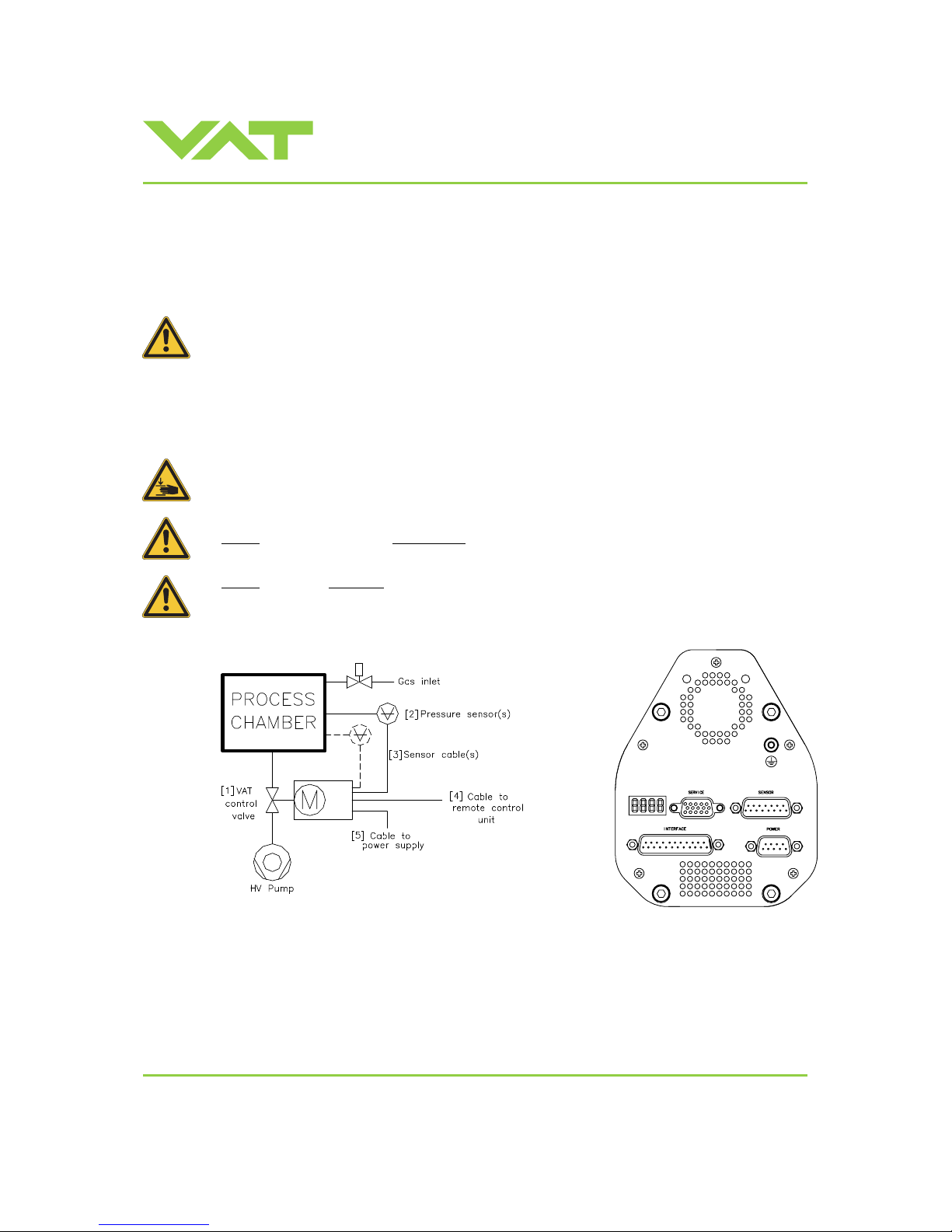
1. Install valve [1] into the vacuum system. Valve seat side should face process chamber. The valve seat side is
indicated by the symbol "∇" on the valve flange.
Caution: Do not tighten the flange screws stronger than indicated under «Tightening torque».
Caution: Do not admit higher forces to the valve than indicated under «Admissible forces».
Note: Make sure that enough space is kept free to do preventive maintenance work. The required space is indicated
on the dimensional drawing.
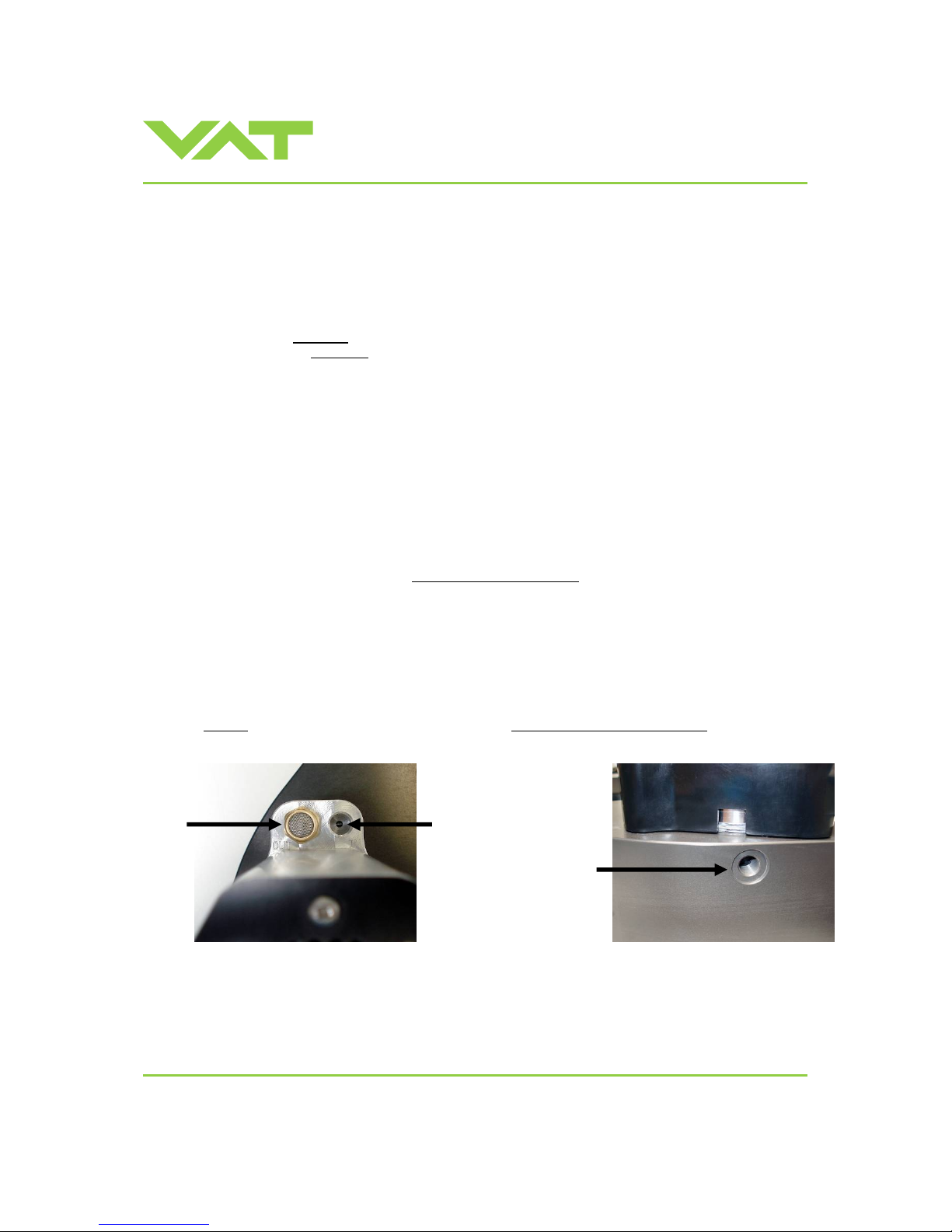
2. Connect compressed air supply
to connection labeled ‘IN’ located at actuator, see Figure 1 below.
Connect compressed air return line
connection labeled ‘OUT’ located at actuator, see Figure 1 below.
Caution: Compressed air pressure must be in the range of: 4 - 7 bar / 55 - 100 psi (above ATM).
Note: Use only clean, dry or slightly oiled air. IN / OUT connections are 1/8“ ISO/NPT internal threads.
3. Install pressure sensor(s) [2] according to the recommendat ions of the sensor manufacturer and directives given
under
«Requirements to sensor connection».
4. Connect sensor cable [3] to sensor(s) and then to valve (connector: SENSOR).
Refer to chapter «Electrical connection» for correct wiring.
Note: Input for second sensor is available on 651 . . - . . . E - . . . . ver sions only.
5. Connect valve to Logic [4] (connector: INTERFACE). Refer to «Logic schematics» f or correct wiring.
6. Connect power supply [5] to val ve (connector: POWER). Refer to chapter «Electrical connection» for correct wiring.
Note: To provide power to the valve motor pins 4 and 8 must be bridged
, otherwise motor interlock is activ e and the
valve enters the safety mode and is not operat ive. Refer also to «Safety mode».
7. This valve has a double sealed rotary feedthr ough and optionally an intermediate pumping port for the actuator shaft.
This port (1/8“ ISO/NPT) could be connected to the vacuum line, see Figure 2 below.
8. This valve may optionally be equipped with a heating device. Connect VAT heating device according to manual of
respective heating device.
9. Perform «Setup procedure» to prepare valv e for operation.
Note: Without
performing the setup procedure the valve will not be able to do pressure control.
Fig. 1 Fig. 2
intermediate
pumping port
IN
OUT
Page 8
Installation, Oper ating & Maintenance Instructions
Series 651 DN 320-400 (I.D. 12“ - 16”), Logic
VAT Vakuumventile AG, CH-9469 Haag, Switzerland
Tel +41 81 771 61 61 Fax +41 81 771 48 30 [email protected] www.vatvalve.com
267736ED
2008-02-26
8/53
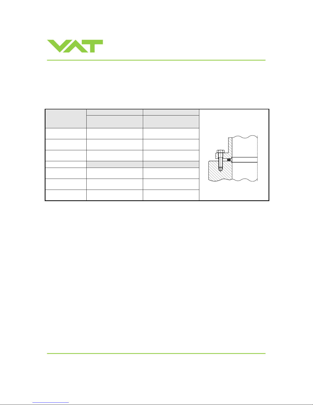
2.3 Tightening torque
Tighten mounting screws of the flanges uniformly in crosswise order. Observe the maximum torque levels in the following
table. Higher tightening torques deforms the valve body and may lead to malfunction of the valve.
2.3.1 Mounting with centering rings
ISO-F ISO-F
Valve size
max. tighten ing torque
(Nm)
max. tightening torque
(lbs . ft)
DN320 / 12“
(65150 - . . . . - . . . . )
17-20 13-15
DN350 / 14“
(65151 - . . . . - . . . . )
–
–
DN400 / 16“
(65152 - . . . . - . . . . )
17-20 13-15
hole depth (mm) hole depth (i nc h)
DN320 / 12“
(65150 - . . . . - . . . . )
18 0.71
DN350 / 14“
(65151 - . . . . - . . . . )
– –
DN400 / 16“
(65152 - . . . . - . . . . )
20 0.79
Caution: Make sure that scr ews are not too long otherwise the valv e body may be damaged.
Note: Use slightly lubricated screws.
Refer to «Spare parts and accessories» for centering rings ordering numbers.
Page 9
Installation, Oper ating & Maintenance Instructions
Series 651 DN 320-400 (I.D. 12“ - 16”), Logic
VAT Vakuumventile AG, CH-9469 Haag, Switzerland
Tel +41 81 771 61 61 Fax +41 81 771 48 30 [email protected] www.vatvalve.com
267736ED
2008-02-26
9/53
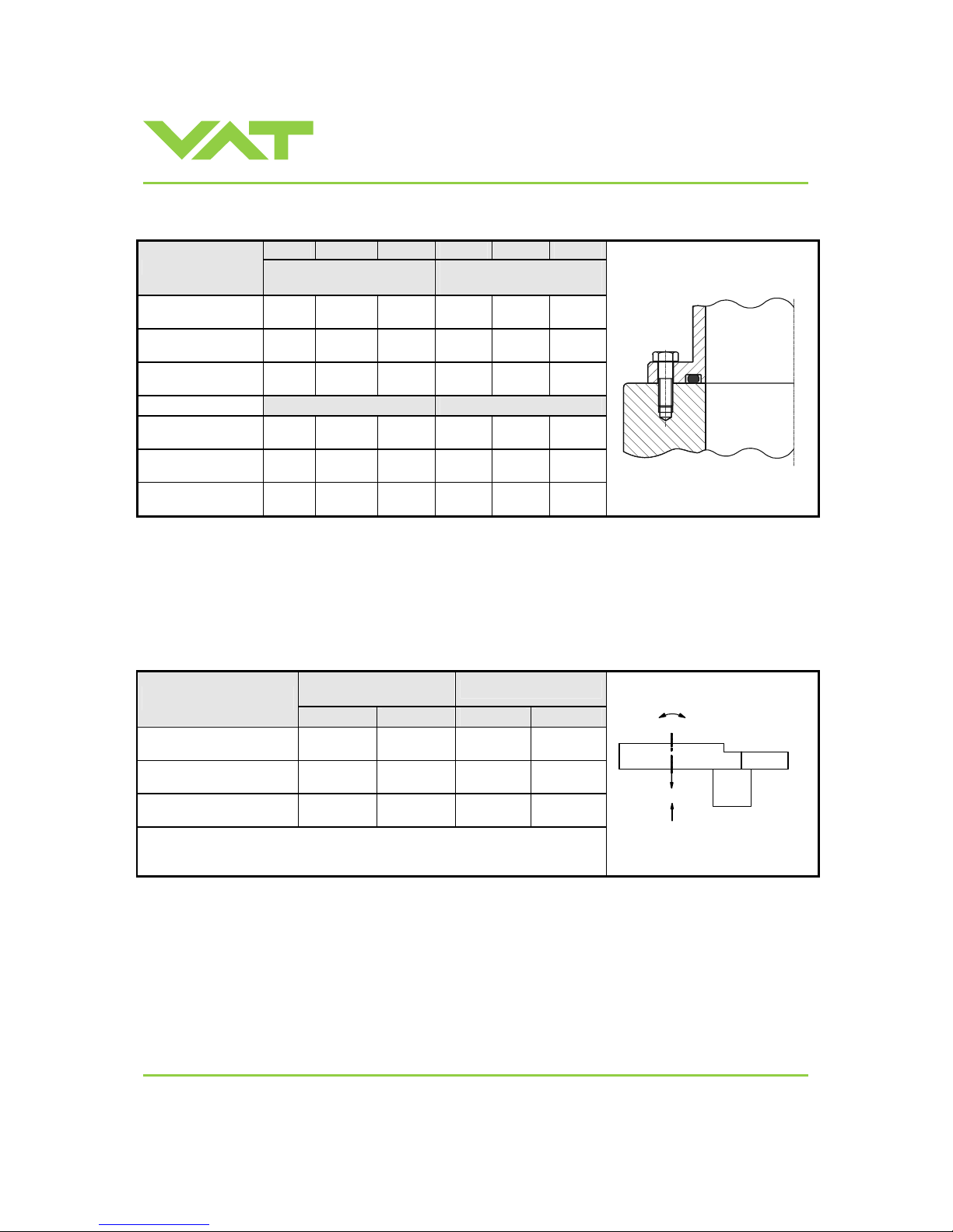
2.3.2 Mount ing with O-ring in grooves
ISO-F JIS ASA-LP ISO-F JIS ASA-LP
Valve size
max. tighten ing torque
(Nm)
max. tightening torque
(lbs . ft)
DN320 / 12“
(65150 - . . . . - . . . . )
65-70 65-70 80-90 48-52 48-52 59-67
DN350 / 14“
(65151 - . . . . - . . . . )
– 65-70 – – 48-52 –
DN400 / 16“
(65152 - . . . . - . . . . )
65-70 115-120 230-240 48-52 85-89 170-178
hole depth (mm) hole depth (i nc h)
DN320 / 12“
(65150 - . . . . - . . . . )
18 18 18 0.71 0.71 0.71
DN350 / 14“
(65151 - . . . . - . . . . )
– 18 – – 0.71 –
DN400 / 16“
(65152 - . . . . - . . . . )
20 25 25 0.79 0.98 0.98
Caution: Make sure that scr ews are not too long otherwise the valv e body may be damaged.
Note: These torques are valid if depth of the mounting screws is min. 1 x thread diameter. Make sure that screws in use
are capable to withstand applied torques. Lubricate screws slightly.
2.4 Admissible forces
Forces from evacuating the system, from the weight of other components, and from baking can lead to deformation and
malfunctioning of the valve. Stress has to be relieved by suitable means, e.g. bellows sections.
Axial tensile or
compressive force «FA»
Bending moment «M»
Valve size
N lb. Nm lbf.
DN320 / 12“
(65150 - . . . . - . . . . )
3000 660 120 90
DN350 / 14“
(65151 - . . . . - . . . . )
3500 770 140 105
DN400 / 16“
(65152 - . . . . - . . . . )
4000 880 160 120
For a combination of both forces (FA and M) the values are invalid.
Verify that the depth of the mounting screws is min. 1 x thread diameter.
Please contact VAT for more information.
F
A
M
Page 10
Installation, Oper ating & Maintenance Instructions
Series 651 DN 320-400 (I.D. 12“ - 16”), Logic
VAT Vakuumventile AG, CH-9469 Haag, Switzerland
Tel +41 81 771 61 61 Fax +41 81 771 48 30 [email protected] www.vatvalve.com
267736ED
2008-02-26
10/53
2.5 Requirements to sensor connection
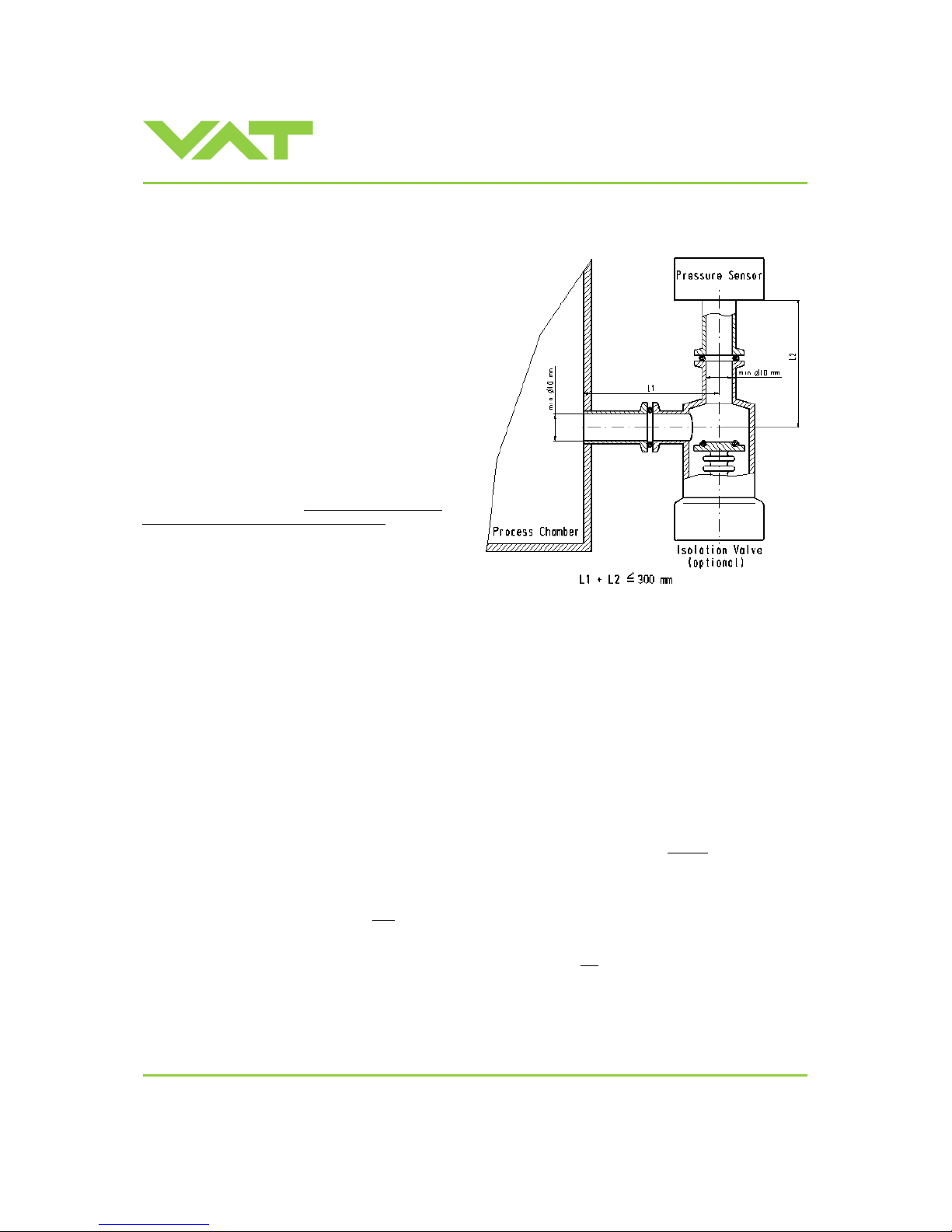
To achieve fast and accurate pressure control a fast
sensor response is required.
Sensor response time: < 50ms
The sensor is normally connected to the chamber by a
pipe. To maintain that the response time is not degraded
by this connection it needs to meet the following
requirements:
Inner diameter of connection pipe: > = 10 mm
Length of connection pipe: < = 300 mm
These conductance guidelines must include all valves
and limiting orifices that may also be present.
Make also sure that there is no obstruction in fron t of
sensor connection port inside the chamber.
The sensor should also be mounted free of mechanical
shock and vibration.
Dynamic stray magnetic fields may introduce noise to
sensor output and should be avoided or shielded.
2.6 Electrical connection
2.6.1 Sensor supply concepts
This valve offers 3 alternative concepts to supply the sensor(s) with power. This depends on the sensor type and valve
version that is used. This valve is av ail able with an optional sensor power supply mod ule (SPS) that converts ±15 VDC
from the 24 VDC.
Concepts:
• External + 24 VDC supplied to POWER connector is feed through to SEN SOR connector to supply 24 VDC
sensors. Refer to chapter «2.6.2 Pow er and sensor connection (+24 VDC sensors)» for schematic and correct
wiring.
• External ±15 VDC supplied to POWER connector is feed through to SENSOR connector to supply ±15 VDC
sensors. Refer to chapter «2.6.3 Powe r and sensor connection (±15 VDC sensors) without
optional SPS module»
for schematic and correct wiring.
• External + 24 VDC supplied to POWER connector is converted i nto ±15 VDC by the valve internal SPS and
supplied to SENSOR connector to supply ±15 VDC sensors. Refer to chapter «2.6.4 Power and sensor
connection (±15 VDC sensors) with
optional SPS module» for schematic and correct wiring.
Valve versions:
• 651 . . - . . G . - . . . . / 651 . . - . . H . - . . . . SPS module not
included
• 651 . . - . . A . - . . . . / 651 . . - . . C . - . . . . SPS module included
Note: The SPS module can be retrofitted. Refer to chapter «Retrofit / replacement procedure» for instruction.
Page 11
Installation, Oper ating & Maintenance Instructions
Series 651 DN 320-400 (I.D. 12“ - 16”), Logic
VAT Vakuumventile AG, CH-9469 Haag, Switzerland
Tel +41 81 771 61 61 Fax +41 81 771 48 30 [email protected] www.vatvalve.com
267736ED
2008-02-26
11/53
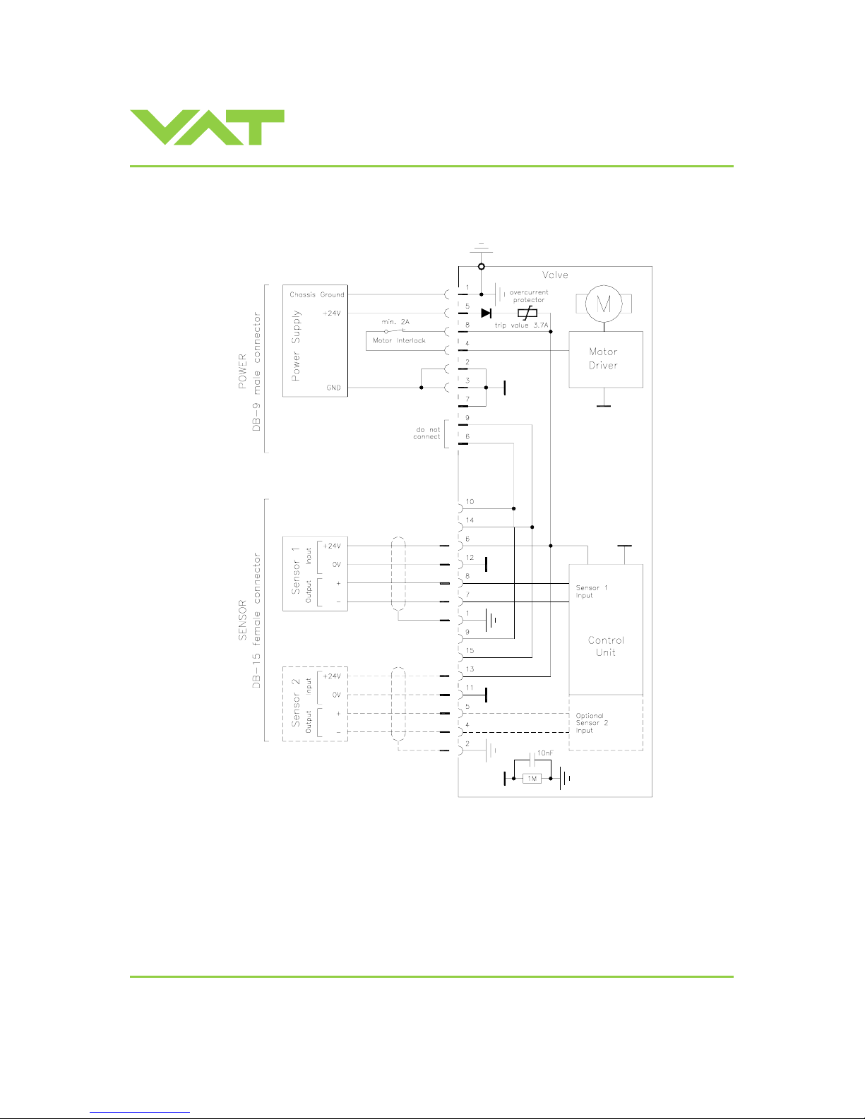
2.6.2 Power and sensor connection (+24 VDC sensors)
[651 . . - . . G . - . . . . / 651 . . - . . H . - . . . . versions recommended]
Note:
• Use shielded sensor cable(s). Keep cable as short as possible, but locate it away from noise sources.
• Connect the ±24 VDC sensors at DB–15 female sensor connector exactly as shown in the drawing above.
Do not connect other pins, that may damage power suppl y or controller!
• Connector: Use only screw s with 4-40UNC thread for fastening the connectors!
Pins 4 and 8 must be
bridged for operation!
An optional switch would allow
for motor interlock to prevent
valve from moving.
Low range sensor may be connected
to sensor 1 or sensor 2 input.
Do configuration accordingly.
Page 12
Installation, Oper ating & Maintenance Instructions
Series 651 DN 320-400 (I.D. 12“ - 16”), Logic
VAT Vakuumventile AG, CH-9469 Haag, Switzerland
Tel +41 81 771 61 61 Fax +41 81 771 48 30 [email protected] www.vatvalve.com
267736ED
2008-02-26
12/53
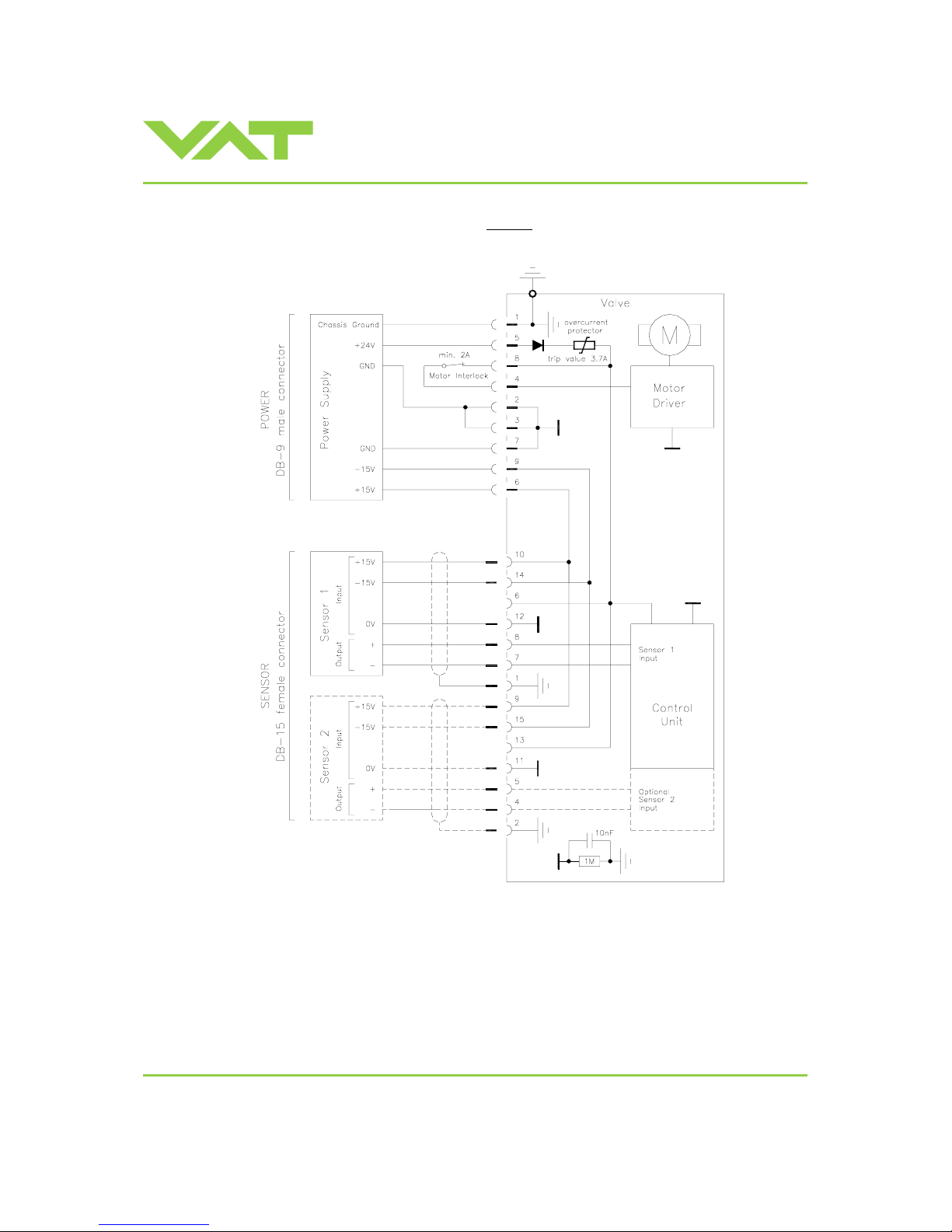
2.6.3 Power and sensor connection (±15 VDC sensors) without
optional SPS module
[651 . . - . . G . - . . . . / 651 . . - . . H . - . . . . versions only]
Note:
• Use shielded sensor cable(s). Keep cable as short as possible, but locate it away from noise sources.
• Connect the ±15 VDC sensors at DB–15 female sensor connector exactly as shown in the drawing above.
Do not connect other pins, that may damage power suppl y or controller!
• Connector: Use only screw s with 4-40UNC thread for fastening the connectors!
Pins 4 and 8 must be bridged for
operation!
An optional switch would allow for motor
interlock to prevent valve from m oving.
Low range sensor may be connected
to sensor 1 or sensor 2 input.
Do configuration accordingly.
Page 13
Installation, Oper ating & Maintenance Instructions
Series 651 DN 320-400 (I.D. 12“ - 16”), Logic
VAT Vakuumventile AG, CH-9469 Haag, Switzerland
Tel +41 81 771 61 61 Fax +41 81 771 48 30 [email protected] www.vatvalve.com
267736ED
2008-02-26
13/53
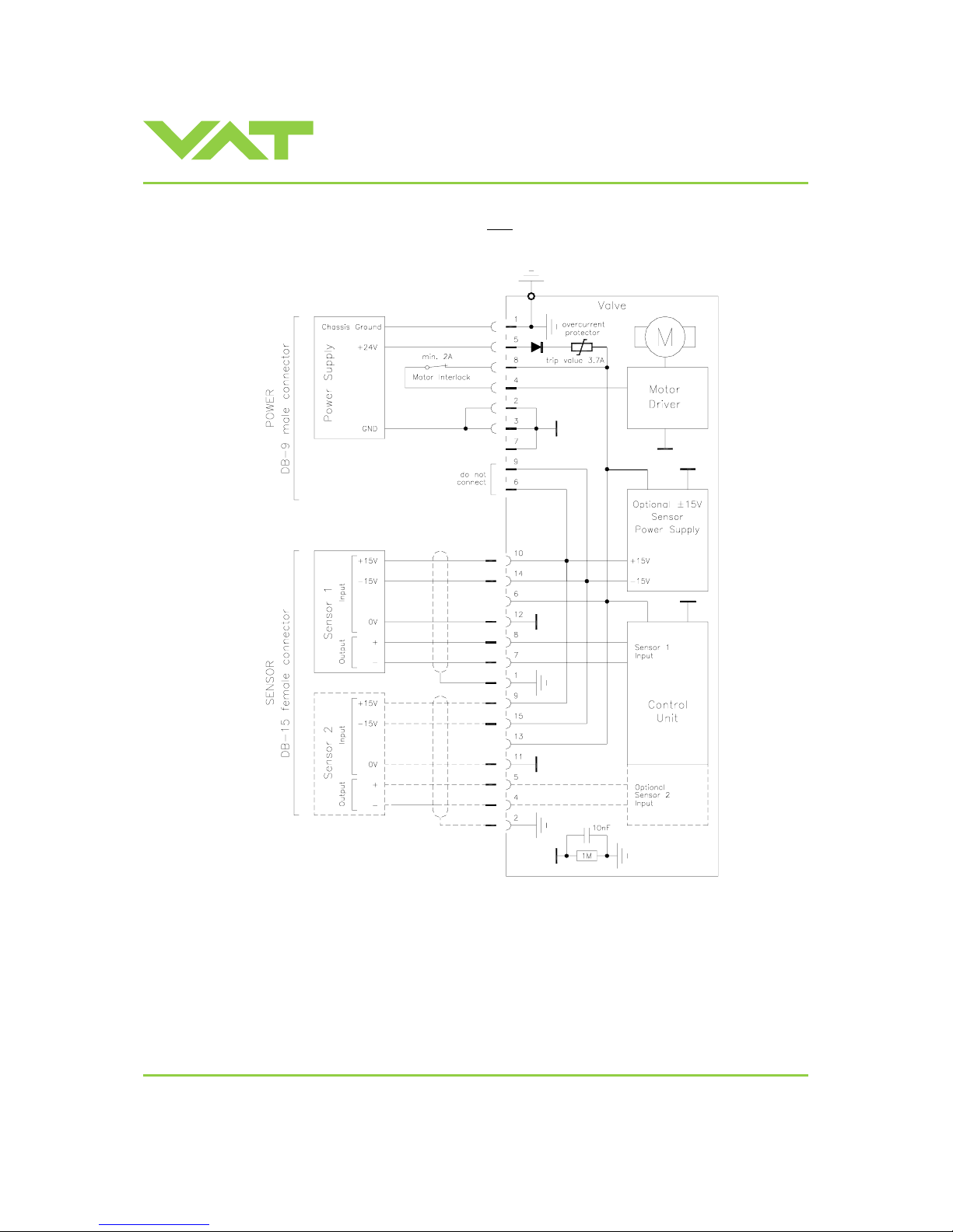
2.6.4 Power and sensor connection (±15 VDC sensors) with
optional SPS module
[651 . . - . . A . - . . . . / 651 . . - . . C . - . . . . versions only]
Note:
• Use shielded sensor cable(s). Keep cable as short as possible, but locate it away from noise sources.
• Connect the ±15 VDC sensors at DB–15 female sensor connector exactly as shown in the drawing above.
Do not connect other pins, that may damage power suppl y or controller!
• Connector: Use only screw s with 4-40UNC thread for fastening the connectors!
Pins 4 and 8 must be
bridged for operation!
An optional switch would allow
for motor interlock to prevent
valve from moving.
Low range sensor may be connected
to sensor 1 or sensor 2 input.
Do configuration accordingly.
Page 14

Installation, Oper ating & Maintenance Instructions
Series 651 DN 320-400 (I.D. 12“ - 16”), Logic
VAT Vakuumventile AG, CH-9469 Haag, Switzerland
Tel +41 81 771 61 61 Fax +41 81 771 48 30 [email protected] www.vatvalve.com
267736ED
2008-02-26
14/53
2.6.5 Logic interface connection
Refer to «Schematics» for wiring information.
2.6.6 Service port connection
The service port (connector: SERVICE) allows to connect the valve to a RS232 port of a computer.
This requires a service cable and a software fr om VA T. You can either use our freeware 'Control View', which can be
downloaded from
www.vatvalve.com or purchase our 'Control Performance Analy zer'.
Alternatively the VAT Service Box 2 can be connected to the service port for setup and local operation.
The service port is not galvanic isolated. Therefore we recommend using this only for setup, testing and maintenance and
not for permanent control.
Refer also to «Local Operation» for details and to «Spare parts / Accessories» for ordering numbers of service cable,
software and Service Box 2.
Connector: Use only screws with 4-40UNC thread for fastening the service port connector!
Page 15
Installation, Oper ating & Maintenance Instructions
Series 651 DN 320-400 (I.D. 12“ - 16”), Logic
VAT Vakuumventile AG, CH-9469 Haag, Switzerland
Tel +41 81 771 61 61 Fax +41 81 771 48 30 [email protected] www.vatvalve.com
267736ED
2008-02-26
15/53
3 Operation
Operation is allowed after completion of the installation procedure only.
3.1 Introduction
This valve is designed for down stream pressure control in vacuum chambers. It can be employed in a pressure control
mode or a position control mode.
In both cases local or remote operation is possible.
3.1.1 Local operation
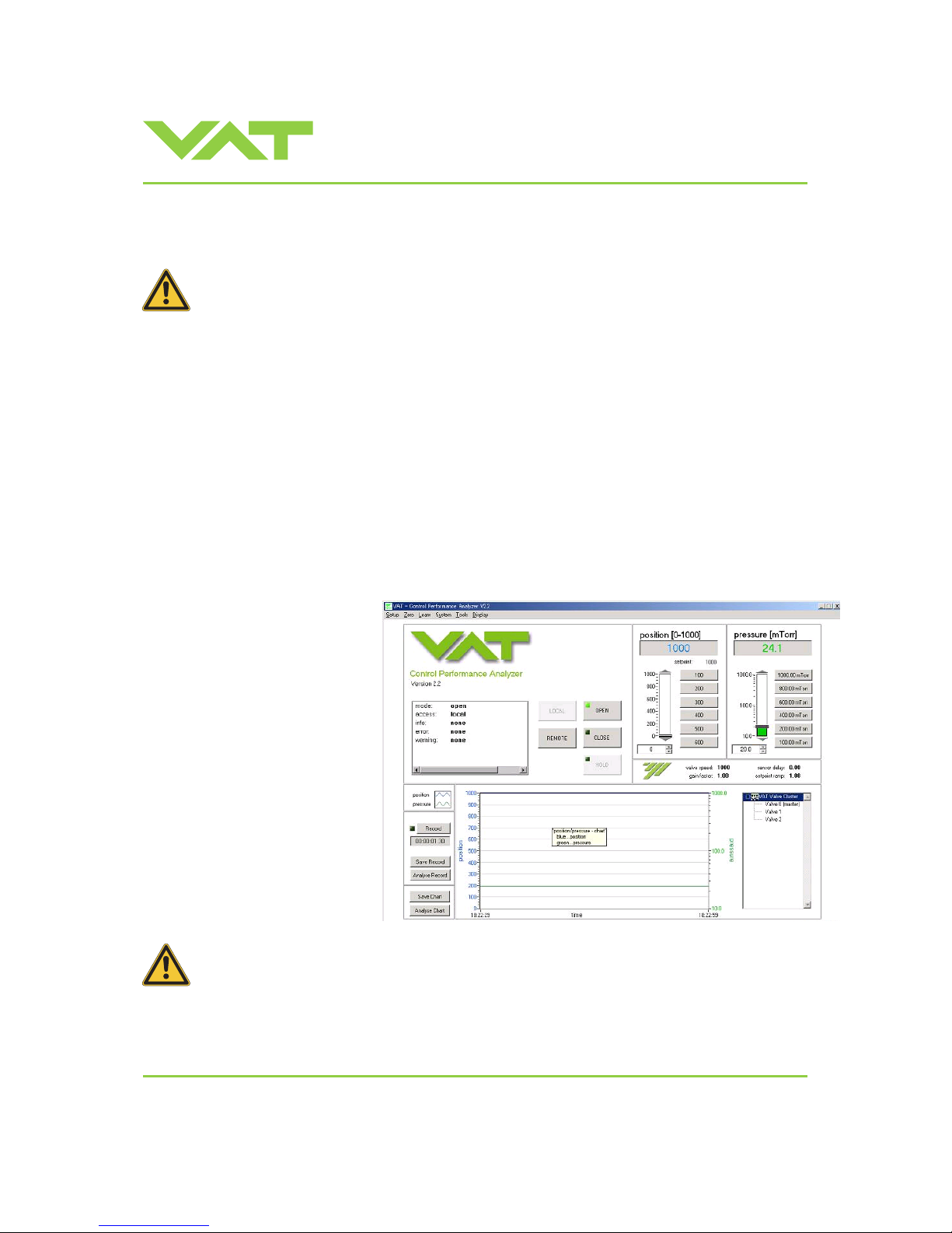
Local operation means that the valve is operated via the service por t using a computer or the Service Box 2. When using
a computer, a service cable and a software from VAT are required. You can either download our freeware 'Control View'
from
www.vatvalve.com or purchase our 'Control Performance Analyzer'.
These software are beneficial especial ly for setup, testing and maintenance.
How to start: Connect serv ice cable, start software and push button ‘LO CAL’ to enable for operation. Then enter menu
Setup/Sensor and do sensor configuration according to your application to make sure that you get the correct pressure
displayed.
‘Control view’ supports:
- parameter setup
- manual control
- numeric monitoring
- basic diagnostic
'Control Performance Analyzer '
supports:
- parameter setup
- manual control
- sequence control
- numeric and graphical
monitoring
- data recording
- data analysis
- advanced diagnostic
When communication to service port is interrupted the valve will change to remote operation.
So when service cable will be disconnected or software will be shut down, the valve returns
automatically to remote operation.
This may result in an immediate movement of the valve depending on remote control.
Refer to «Spare parts / Accessories» for ordering numbers of service cable, software and Service Box 2.
Page 16
Installation, Oper ating & Maintenance Instructions
Series 651 DN 320-400 (I.D. 12“ - 16”), Logic
VAT Vakuumventile AG, CH-9469 Haag, Switzerland
Tel +41 81 771 61 61 Fax +41 81 771 48 30 [email protected] www.vatvalve.com
267736ED
2008-02-26
16/53
3.1.2 Remote operation
This product is equipped with a Logic interface to all ow for remote operation. See section «Logic Int erface» for details.
‘Control View’ software, 'Control Performance Analyzer' software or 'Service Box 2' may be used for monitoring during
remote control.
Note: In case ‘Control View’ or ‘Control Performance Analyzer’ software is connected to valve make sure ‘REMOTE’
button is pushed to enable for remote operation. In case Service Box 2 is connected to valve make sure the LED on
button ‘LOCAL’ is OFF for remote operation.
3.1.3 Safety mode
By means of an external switch (see connecti on diagrams «Electrical connection») the motor power supply can be
interrupted. In this case the valve enters the ‘safety mode’. This motor interlock prevents the valve from moving (e.g.
maintenance work). Data reading fr om the control unit remains possible.
When motor interlock is active during power up the valve directly enters the ‘safety mode’ and is not able to synchronize.
Display shows ‘D C’ or ‘D999’. In this case synchronization cycle will be done when motor interlock is deactivated. Then
Display shows ‘INIT’ for a moment followed by ‘SYNC’.
When ‘safety mode’ is entered from operation (i.e. pressure control mode), the uni t will automatically switch to positio n
control mode and remain at current position. Once motor interlock is deactiv a ted the unit remains in position control mode.
3.2 Operation under increased temperature
This valve may be operated in the temperature range mentioned in chapter «Technical data».
3.3 Behavior during power up
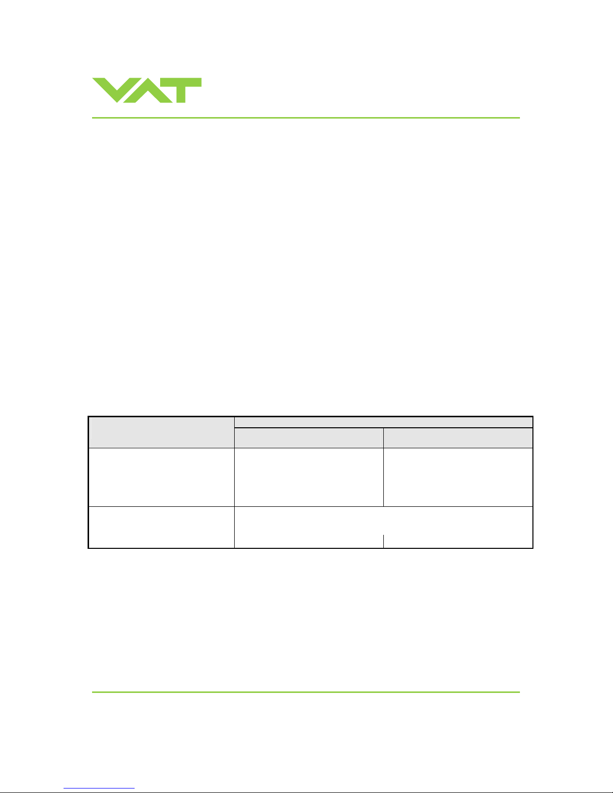
Reaction of valve:
Valve position before
power up:
Valve power up configuration = closed
(default)
Valve power up configuration = open
Closed (isolated) Valve remains closed.
Display shows alternately ‘C C’ and
‘INIT’.
Synchronization will be done when first
movement command is received.
Valve runs to max. throttle position to
detect the limit stops to synchronize.
Display shows configuration of product
resp. ‘SYNC’ until synchronization is
done.
Valve position after power up is open.
Valve runs to max. throttle position to detect limit stop for synchroni zation.
Display shows configuration of product resp. ‘SYNC’ until synchronization is
done.
All other than closed (not isolated)
Valve position after power up is closed
Valve position after power up is open
Refer also to chapter «Display informati on».
Page 17
Installation, Oper ating & Maintenance Instructions
Series 651 DN 320-400 (I.D. 12“ - 16”), Logic
VAT Vakuumventile AG, CH-9469 Haag, Switzerland
Tel +41 81 771 61 61 Fax +41 81 771 48 30 [email protected] www.vatvalve.com
267736ED
2008-02-26
17/53
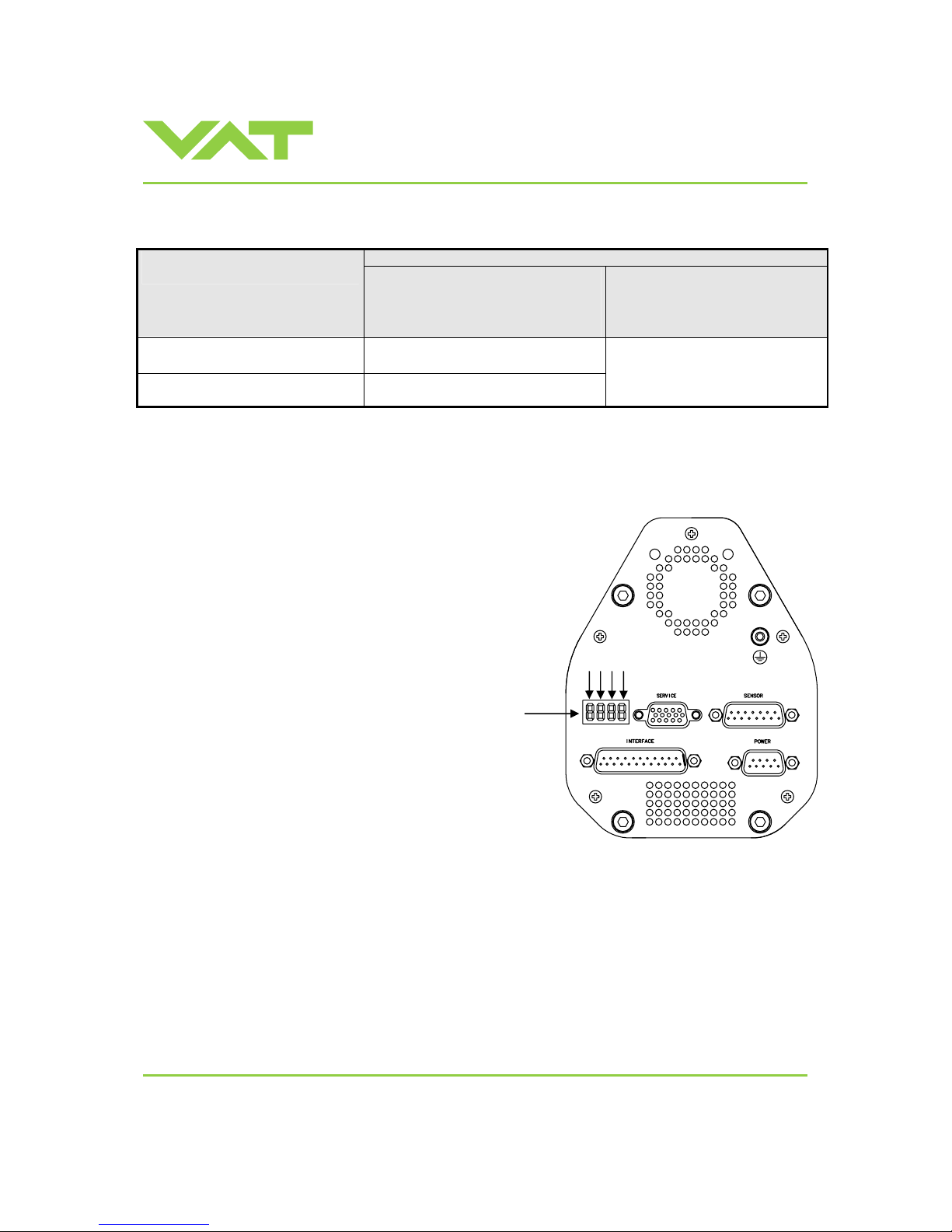
3.4 Behavior in case of power failure
Reaction of valve:
Valve position before
power failure:
Without Power Failure Option (PFO)
651 . . - . . G . - . . . .
651 . . - . . A . - . . . .
651 . . - . . T . - . . . .
651 . . - . . V . - . . . .
With Power Failure Option (PFO)
651 . . - . . H . - . . . .
651 . . - . . C . - . . . .
651 . . - . . U . - . . . .
651 . . - . . W . - . . . .
Closed (isolated) Valve remains closed.
Valve open or in any intermediate
position
Sealing ring moves down and blocks the
pendulum plate at the current position.
Valve will close or open depending
on valve configuration *).
Default is not defined.
Display indicates F.
*) Provided that battery pack of the VAT controller is charged. Charging time after power up is 2 minutes max..
All parameters are stored in a power fail save memory.
3.5 Display information
There is a 4 digit display located on the panel.
It displays configuration, status and position
information. For details refer to following
tables.
Display
1 2 3 4
Page 18
Installation, Oper ating & Maintenance Instructions
Series 651 DN 320-400 (I.D. 12“ - 16”), Logic
VAT Vakuumventile AG, CH-9469 Haag, Switzerland
Tel +41 81 771 61 61 Fax +41 81 771 48 30 [email protected] www.vatvalve.com
267736ED
2008-02-26
18/53
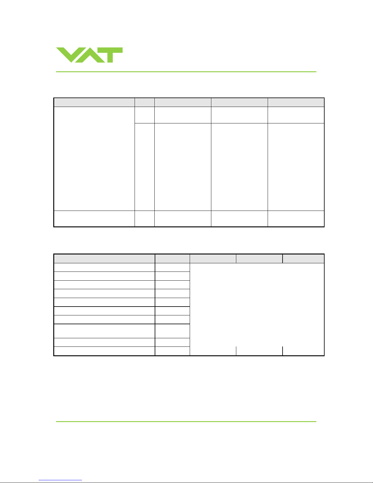
Power up:
Description Digit 1
Digit 2 Digit 3 Digit 4
1 E 0 0
At first all dots are illuminated
then configuration is displayed:
• Firmware version [e.g. 1E00]
(1
st
information for about 2s)
• Controller configuration
(2
nd
information for about 2s)
In case D C or D999 is displayed,
motor interlo c k is a c tive. Refer to
«Safety mode» for details.
If valve is closed (isolated) display
shows alternately C C and INIT.
Synchronization will be done
when first movement command is
received.
1
= Logic interface
0
= basic
1
= with SPS
1)
2
= with PFO
2)
3
= with SPS
1)
and PFO
2)
1
= 1 sensor version
2
= 2 sensor version
SYNC indicates that
synchronization is running.
S Y N C
1) SPS = opt ional ±15 VDC Sensor Power Supply module 2) PFO = optional Power Failure Option
Operation:
Description / Mode Digit 1 Digit 2 Digit 3 Digit 4
PRESSURE CONTROL mode
P
POSITION CONTROL mode
V
Valve closed
C
Valve open
O
HOLD (position frozen) activated
H
ZERO running
Z
LEARN running
L
Safety mode established. Refer to «Safety
mode» for details.
D
0 . . . 100
= valve position (%, 0 = closed / 100 = open)
Power failure
F
Service request 1)
S R
1)
If SR is blinking alternatively with the actual mode display (e.g. P.11 ⇔ ..SR) the valve requires cleaning.
Page 19
Installation, Oper ating & Maintenance Instructions
Series 651 DN 320-400 (I.D. 12“ - 16”), Logic
VAT Vakuumventile AG, CH-9469 Haag, Switzerland
Tel +41 81 771 61 61 Fax +41 81 771 48 30 [email protected] www.vatvalve.com
267736ED
2008-02-26
19/53
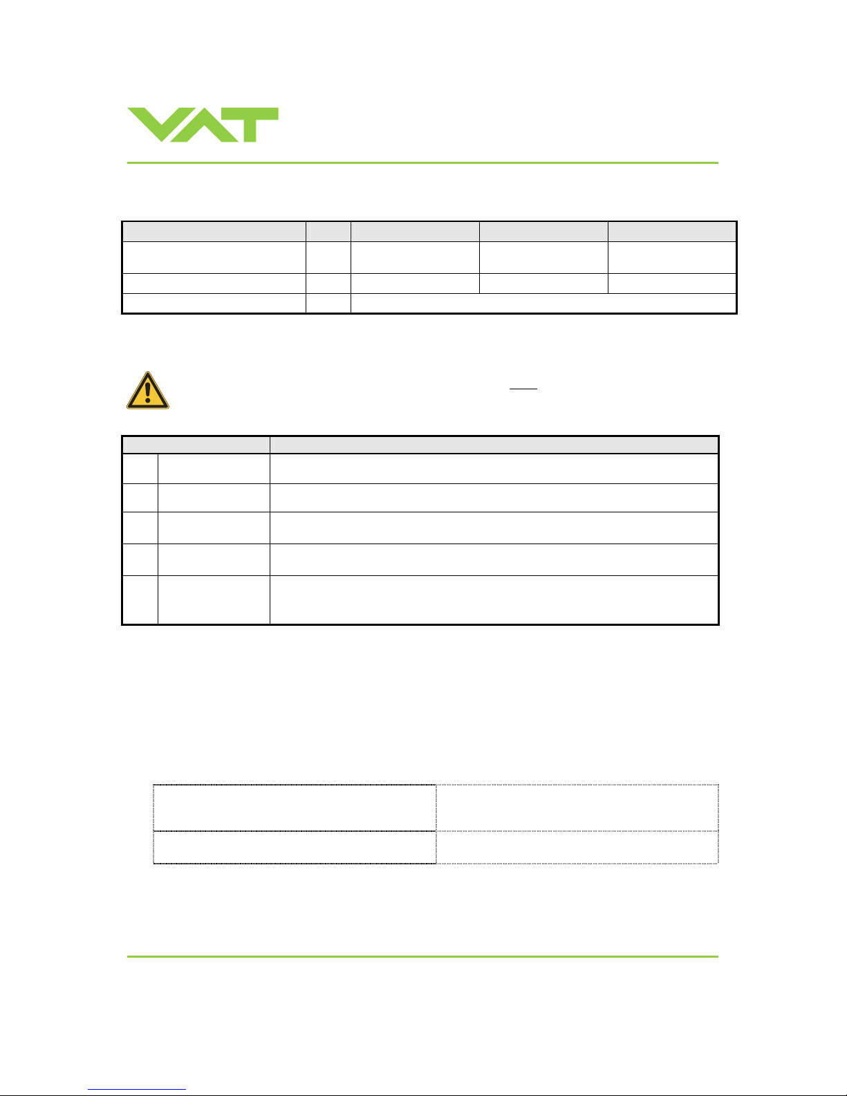
Errors:
Description Digit 1
Digit 2 Digit 3 Digit 4
Compressed air failure
(< 4 bar / 55 psi)
A I R f
Compressed air on exhaust
A I R x
Fatal error occurred
E
Error code. Refer to «Trouble shooting» for details
3.6 Setup procedure
To enable this valve for pressure control setup steps 1 to 5 must
be performed.
In case position control is required only it’s sufficient to perform steps 1 and 2.
Setup step Description
1
POWER UP
Turn on external + 24VDC power supply (and external ±15 VDC for sensor power
supply if required). Refer to chapter «Behavior during power up» for details.
2
INTERFACE
CONFIGURATION
Refer to chapter «Interface configuration» for details.
3
VALVE
CONFIGURATION
Basic configurations of the valve must be adapted according to application needs.
Refer to chapter «Valve configuration» for details.
4
ZERO
Compensation of the sensor offset voltage.
Refer to chapter «ZERO» for details.
5
LEARN
Determination of the vacuum system characteristic to accommodate the PID
controller. Refer to chapter «LEARN» for details.
Note: Without LEARN the valve is not able to run pressure control
3.6.1 Interface configuration
Interface configuration must be adapted according to application needs.
• Functionality of digital inputs CLOSE VALVE and OPEN VALVE must be selected.
These may be configured as ‘not inverted‘ or ‘inverted‘. Default is ‘not inverted‘.
• LEARN range configuration for remote operation must be selected.
This may either be ‘full range’ or pressure limit accor d ing of analog SETPOINT input. Default is ‘full range‘.
Local operation:
(‘Control View’, ‘Control Performance Analyzer’ or
‘Service Box 2‘)
Remote operation:
Do configuration in menu ‘Setup / Interfa ce’.
Note: It’s not possible to do ‘Interface configur ation‘
via remote operation.
Page 20
Installation, Oper ating & Maintenance Instructions
Series 651 DN 320-400 (I.D. 12“ - 16”), Logic
VAT Vakuumventile AG, CH-9469 Haag, Switzerland
Tel +41 81 771 61 61 Fax +41 81 771 48 30 [email protected] www.vatvalve.com
267736ED
2008-02-26
20/53
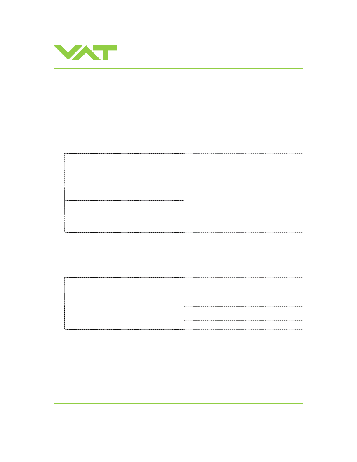
3.6.2 Valve and sensor configuration
Basic valve configuration must be adapted according to application needs.
• Definition of valve plate position (CLOSE or OPEN) after power up sequence. Default is ‘close‘.
• Definition of valve plate position (CLOSE or OPEN) in case of a power failure. Default is ‘not defined‘.
Only for versions that have Power Fail Option equipped [651 . . - . . C . - . . . . or 651 . . - . . H . - . . . . ].
• ZERO function. This may be ‘disabled’ or ‘enabled’. Default is ‘enabled‘. Refer also to «ZERO».
• Sensor configuration for 2 sensor version [651 . . - . . . E - . . . .].
Refer also to «Pressure control operation with 2 sensors».
Local operation:
(‘Control View’, ‘Control Performance Analyzer’ or
‘Service Box 2‘)
Remote operation:
1. Do power up configuration in menu
‘Setup / Valve’.
2. Do power fail configuration in menu
‘Setup / Valve’.
Note: It’s not possible to do ‘Valve and sensor
configuration‘ via remote operation.
3. Enable or disable ZERO function in menu
‘Setup / Sensor’.
4. Do 2 sensor configuration in menu
‘Setup / Sensor’.
3.6.3 ZERO
ZERO allows for the compensation of the sensor offset voltage.
When ZERO is performed the current value at the sensor input is equated to pressure zero. In case of a 2 sensor system
both sensor inputs will be adjusted. A max. offset voltage of +/-1.4V can be compensated
. The offset value can be read
via local and remote operation.
Local operation:
(‘Control View’, ‘Control Performance Analyzer’ or
‘Service Box 2‘)
Remote operation:
(Refer to chapter «Digital inputs» f o r details)
1. Send OPEN VALVE
2. Wait until process chamber is evacuated and
sensor signal is not shifting anymore.
Go to menu ‘Zero / ZERO’ and follow instructions.
3. Send ZERO
Note: Do not perform ZERO as long as pressure gauge voltage is shifting otherwise incorrect pressure reading is the
result. Refer to manual of sensor manufacturer for warm up time.
Note: Do not perform ZERO , if the base pressure of your vacuum system is higher than 1‰ of sensor full scale. We
recommend disabling ZERO function in this case; refer to «Valve configuration» of the setup procedure. Otherwise
incorrect pressure reading is the result.
Page 21

Installation, Oper ating & Maintenance Instructions
Series 651 DN 320-400 (I.D. 12“ - 16”), Logic
VAT Vakuumventile AG, CH-9469 Haag, Switzerland
Tel +41 81 771 61 61 Fax +41 81 771 48 30 [email protected] www.vatvalve.com
267736ED
2008-02-26
21/53
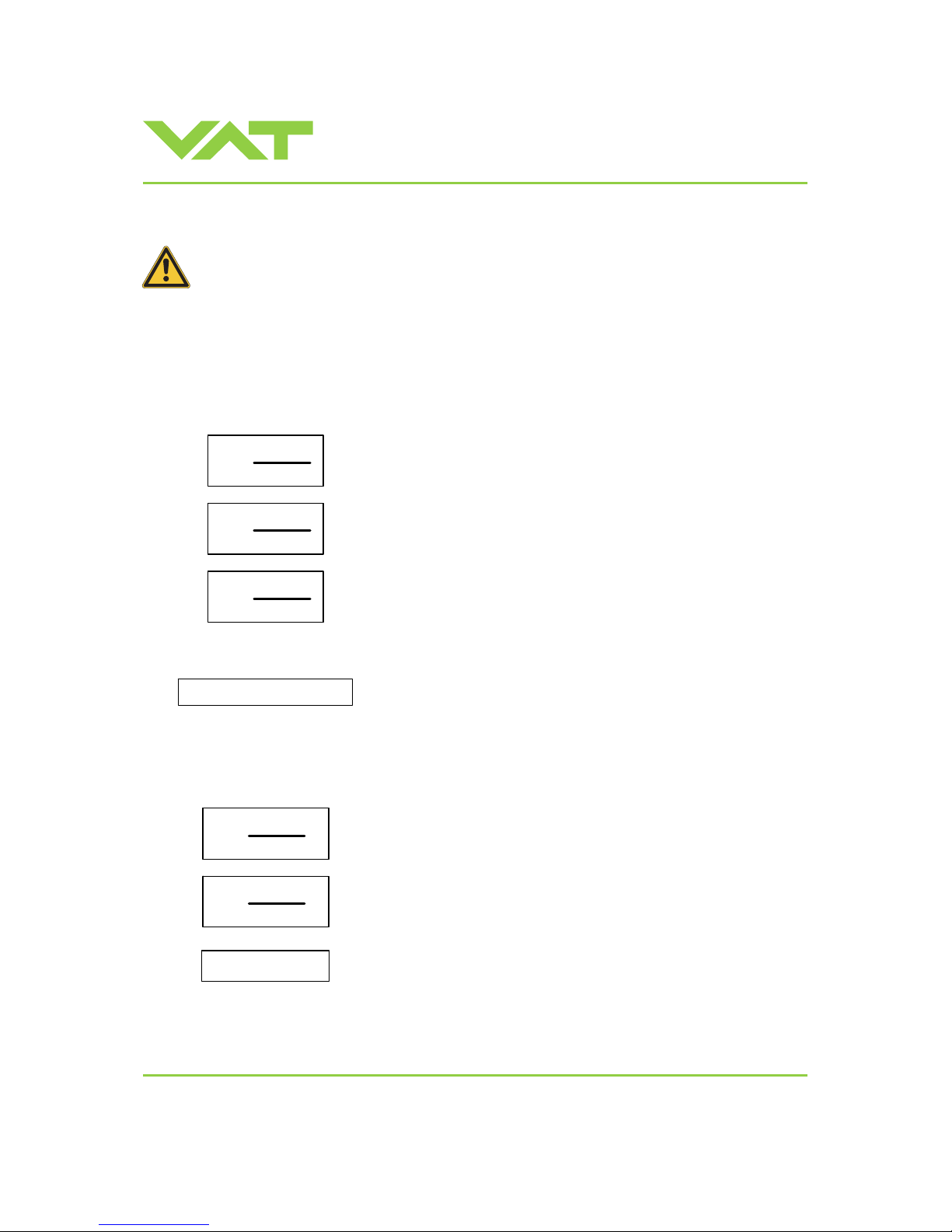
3.6.4 LEARN
LEARN adapts the PID controller of the valve to the vacuum system and its operating conditions. LEARN must be
executed only once during system setup.
The LEARN routine determines the characteristic of the vacuum system. Based on this, the PID controller is able to run
fast and accurate pressure control cycles.
This characteristic depends on various parameters such as chamber volume, conductance and flow regime. T herefore it
must be performed with a specific gas flow according to instruction below.
The result of LEARN is a pressure versus valve position data table. This table is used to adapt the PID parameters. The
data table is stored in the device memory which is power fail save. The data table can be up-/downl oaded via ‘Control
Performance Analyzer’ software or remote interface. Due to encoding the data may not be inter preted directly.
By an OPEN VALVE, CLOSE VALVE, POSITION CONTROL or PRESSURE CONTROL command the routine will be
interrupted.
Local operation:
(‘Control View’, ‘Control Performance Analyzer’ or
‘Service Box 2‘)
Remote operation:
(Refer to chapter «Digital inputs» fo r details)
1. Set OPEN VALVE
2. Set specific gas flow according to calculation
below and wait until flow is stable.
Autolearn does not need to be performed with
the process gas. Instead N
2
or Ar may be used.
3. Set SETPOINT ( = pressure limit for learn) to p
max
(max. pressure to control during process)
4. Set LEARN
Go to ‘Learn / LEARN’ menu and follow instructions.
Note: Gasflow calculation according to
recommendation below is done automatically based
on inputs.
5. Reset OPEN VALVE
Note: Sensor signal must not shift during LEARN. Wait until sensor signal is stable before LEARN is performed.
Note: Learn may take several minutes. Do not interrupt the routine as a single full run is required to ensure fast and
accurate pressure control. The PID controller covers 5% to 5000% of the gas flow which was used for learn.
Page 22
Installation, Oper ating & Maintenance Instructions
Series 651 DN 320-400 (I.D. 12“ - 16”), Logic
VAT Vakuumventile AG, CH-9469 Haag, Switzerland
Tel +41 81 771 61 61 Fax +41 81 771 48 30 [email protected] www.vatvalve.com
267736ED
2008-02-26
22/53
Gasflow calculation for LEARN :
Do not apply a different gasflow for learn than determined below. Otherwise pressure control
performance may be insufficient.
Note: Required pressure / flow regime must be known to calculate the most suitable learn gas flow fo r a specif ic
application.
1. At first it is necessary to find out about the required control range respectively its conductance values. Each working
point (pressure / flow) must be calculated w ith one following formulas.
Choose the applicable formula depending on units you are familiar with.
1000 • q
WP
CWP =
pWP
C
WP
required conductance of working point [l/s]
q
WP
gasflow of working point [Pa m3/s]
p
WP
pressure of working point [Pa]
q
WP
CWP =
pWP
C
WP
required conductance of working point [l/s]
q
WP
gasflow of working point [mbar l/s]
p
WP
pressure of working point [mbar]
q
WP
CWP =
78.7
•
pWP
C
WP
required conductance of working point [l/s]
q
WP
gasflow of working point [sccm]
p
WP
pressure of working point [Torr]
2. Out of these calculated conductance values choose the lowest.
CR = min(C
WP1, CWP2, . . . , CWPn
)
CR required lower conductance [l/ s]
C
WPx
required conductance of working points [l/s]
Note: To make sure that the valve is capable to control the most extreme working point verify that
C
R
≥ C
min
of the valve (refer to «T echnical data»).
3. Calculate gasflow for learn. Choose the applicable formula depending on units you are familiar w ith.
p
max
• C
R
qL =
2000
q
L
gasflow for learn [Pa m3/s]
p
max
max. pressure to control [Pa]
C
R
required lower conductance [l/s]
p
max
• C
R
qL =
2
q
L
gasflow for learn [mbar l/s]
p
max
max. pressure to control [mbar]
C
R
required lower conductance [l/s]
qL = 39.4 • p
max
• C
R
q
L
gasflow for learn [sccm]
p
max
max. pressure to control [Torr]
C
R
required lower conductance [l/s]
Page 23
Installation, Oper ating & Maintenance Instructions
Series 651 DN 320-400 (I.D. 12“ - 16”), Logic
VAT Vakuumventile AG, CH-9469 Haag, Switzerland
Tel +41 81 771 61 61 Fax +41 81 771 48 30 [email protected] www.vatvalve.com
267736ED
2008-02-26
23/53
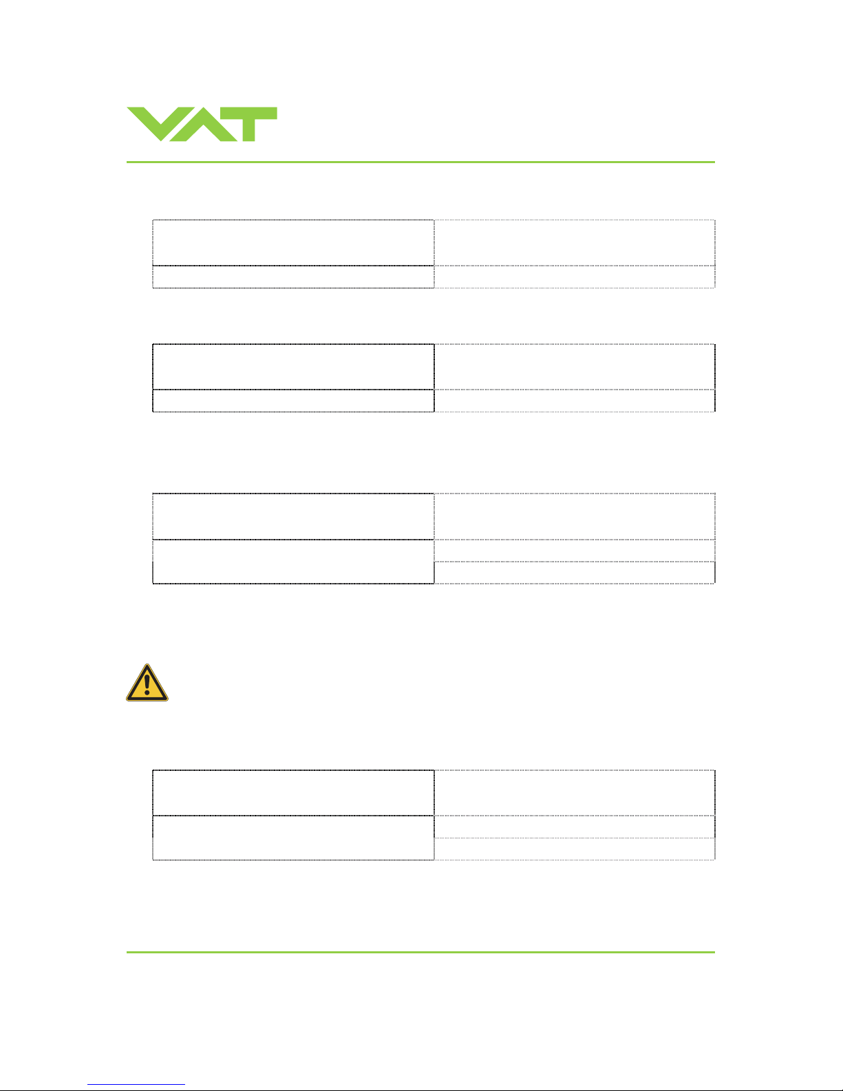
3.7 Close valve
Local operation:
(‘Control View’, ‘Control Performance Analyzer’ or
‘Service Box 2‘)
Remote operation:
(Refer to chapter «Digital inputs» f o r details)
Push CLOSE button Send CLOSE VALVE
3.8 Open valve
Local operation:
(‘Control View’, ‘Control Performance Analyzer’ or
‘Service Box 2‘)
Remote operation:
(Refer to chapter «Digital inputs» f o r details)
Push OPEN button Send OPEN VALVE
3.9 Position control
The valve position is directly controlled according to the position setpoint.
Local operation:
(‘Control View’, ‘Control Performance Analyzer’ or
‘Service Box 2‘)
Remote operation:
(Refer to chapter «Digital inputs» and «Analog inp uts
and outputs» for details)
1. Set CONTR OL MODE to PO SITION CONTROL
Select or enter position setpoint
2. Set position SETPOINT
Note: In case CLOSE VALVE, OPEN VALVE or HOLD is also set these have higher priorit y.
3.10 Pressure control
To prepare valve for PRESSURE CONTROL perform complete «Setup procedure».
The valve has parameters that may be modified to tune pressure control performance.
Refer to «Tuning of control performance».
The included PID controller controls the chamber pressure according to the pressure setpoint by means of the val ve
position. The PID controller works with an adaptive algorithm to achieve best results under altering conditions (gasflow,
gas type).
Local operation:
(‘Control View’, ‘Control Performance Analyzer’ or
‘Service Box 2‘)
Remote operation:
(Refer to chapter «Digital inputs» and «Analog inp uts
and outputs» for details)
1. Set CONTROL MODE to PRESSURE CONTROL
Select or enter pressure setpoint
2. Set pressure SETPOINT
Note: In case CLOSE VALVE, OPEN VALVE or HOLD is also set these have higher priority.
Page 24

Installation, Oper ating & Maintenance Instructions
Series 651 DN 320-400 (I.D. 12“ - 16”), Logic
VAT Vakuumventile AG, CH-9469 Haag, Switzerland
Tel +41 81 771 61 61 Fax +41 81 771 48 30 [email protected] www.vatvalve.com
267736ED
2008-02-26
24/53
3.10.1 Operation with 2 sensors
[applicable with 651 . . - . . . E - . . . . version only]
If 2 sensor operation is enabled, changeover between the sensors is done automatically during pressure control. For
configuration refer to chapter «Setup procedure». We recommend a ratio of 10:1 between the pressure gauges. Max. ratio
is 100:1. It is required that the high range pressure gauge is connected to sensor 1 input and the low range pressure
gauge to the sensor 2 input.
Between 90 and 100% of the low range sensor full scale, the low range sensor is phased out while high range sensor is
phased in. This maintains a functional response behavio r in case of small calibration errors between the two sensors. The
pressure output in this range is a blend between both sensors.
For monitoring purpose each sensor signal may be read out individually.
Note: Make sure that both sensors are calibrated.
Note: Do not close optional gauge isolation valves during the transition phase between the sensors.
Page 25
Installation, Oper ating & Maintenance Instructions
Series 651 DN 320-400 (I.D. 12“ - 16”), Logic
VAT Vakuumventile AG, CH-9469 Haag, Switzerland
Tel +41 81 771 61 61 Fax +41 81 771 48 30 [email protected] www.vatvalve.com
267736ED
2008-02-26
25/53
3.10.2 Tuning of control performance
Normally the default settings will r e sult in good pressure control performance. For some applications tuning may be
required to improve performance.
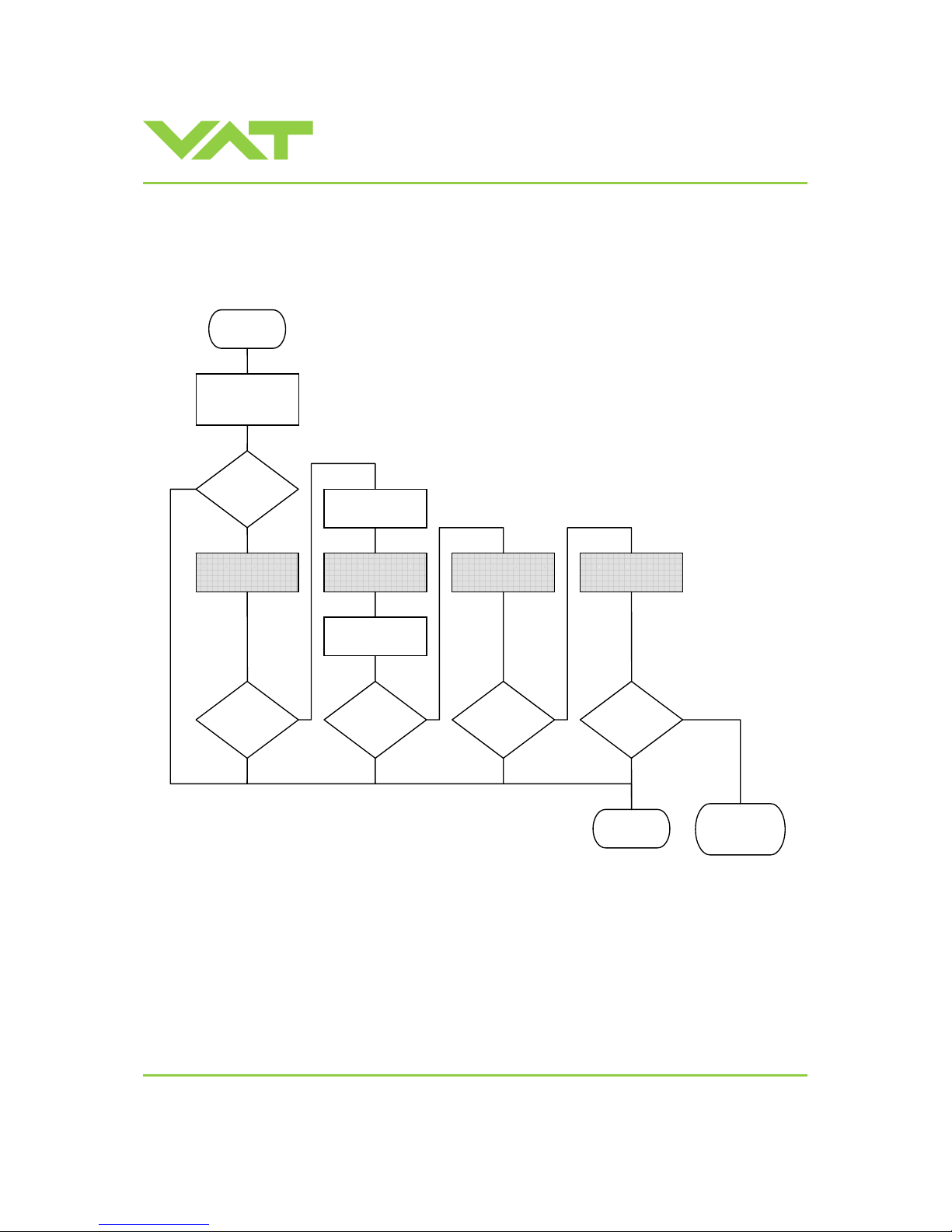
The tuning procedures for each parameter (grey boxes) and its default values are described separately below. Strictly
keep the procedure order.
Required information for support:
• Go to ‘Tools / Create Diagnostic File’ in ‘Control View’ resp. ‘Control Performance Analyzer’ and save file
• Pressure / flow / gas conditions to be controlled
• Chamber volume
• Pumping speed (l/s) and pump type (e.g. turbo pump)
• System description
• Problem description
Send diagnostic file with and all required information to [email protected]
No
No
No
No
No
Gain factor
adjustment
Pressure
control
ok ?
Sensor delay
adjustment
Gain factor
adjustment
Setpoint ramp
adjustment
Valve speed
adjustment
Start
End
Pressure
control
ok ?
Pressure
control
ok ?
Pressure
control
ok ?
Contact
VAT
Pressure
control
ok ?
Reset gain
factor to 1.0
Set all
paramters to
default
Page 26
Installation, Oper ating & Maintenance Instructions
Series 651 DN 320-400 (I.D. 12“ - 16”), Logic
VAT Vakuumventile AG, CH-9469 Haag, Switzerland
Tel +41 81 771 61 61 Fax +41 81 771 48 30 [email protected] www.vatvalve.com
267736ED
2008-02-26
26/53
3.10.2.1 Gain factor adjustment
The gain factor effects:
• Stability
• Response time
Default value is 1. Adjustment range is from 0.0001 to 7.5.
Higher gain results in: faster response higher over- / undershoot of pressure
Lower gain results in: slower response lower over- / undershoot of pressure
Adjustment procedure:
1. Start with gain factor 1.0
2. Open valve.
3. Control a typical pressure / flow situat ion.
4. Repeat from step 2 with lower (higher) gain factors until optimal pressure response is achieved and stability is ok.
Note: Normally adjustments dow n to gain factors of 0.42 should lead to good results. Otherwi se you may need to
improve sensor connection. Refer to «Requiremen ts to sensor connection».
Local operation:
(‘Control View’, ‘Control Performance Analyzer’ or
‘Service Box 2‘)
Remote operation:
Do configuration in menu ‘Setup / Control Parameter’.
Note: It’s not possible to do ‘Interface configuration‘
via remote operation.
3.10.2.2 Sensor delay adjustment
Sensor delay adjustment effects:
• Stability
Default value is 0. Adjustment range is from 0 to 1.0s.
Pipes and orifices for sensor attachment delay response time and so badly impact pressur e control stability.
By adapting this parameter to the approximate delay time stability problems can be reduced. But control response time will
be slowed down by this measure.
Note: Whenever possible sensors should be attached to the chamber according to «Requirements to sensor connect ion».
This is the most effective measure against stabili ty issues. If your gauge attachment fulfills these criteria do not use this
parameter.
Adjustment procedure:
1. Start with gain factor 1.0 and sensor delay 0s.
2. Open valve.
3. Control a typical pressure / flow situat ion.
4. Repeat from step 2 with higher sensor delays until best possible stability is achieved.
5. Adjustment gain factor again. Refer to «G ain factor adjustment».
Local operation:
(‘Control View’, ‘Control Performance Analyzer’ or
‘Service Box 2‘)
Remote operation:
Do configuration in menu ‘Setup / Control Parameter’.
Note: It’s not possible to do ‘Interface configuration‘
via remote operation.
Page 27
Installation, Oper ating & Maintenance Instructions
Series 651 DN 320-400 (I.D. 12“ - 16”), Logic
VAT Vakuumventile AG, CH-9469 Haag, Switzerland
Tel +41 81 771 61 61 Fax +41 81 771 48 30 [email protected] www.vatvalve.com
267736ED
2008-02-26
27/53
3.10.2.3 Setpoint ramp adjustment
Setpoint ramp effects:
• Undershoot of pressure
• Response time
Default value for S
RAMP
is 1. Adjustment range for S
RAMP
is from 0 to 10 s.
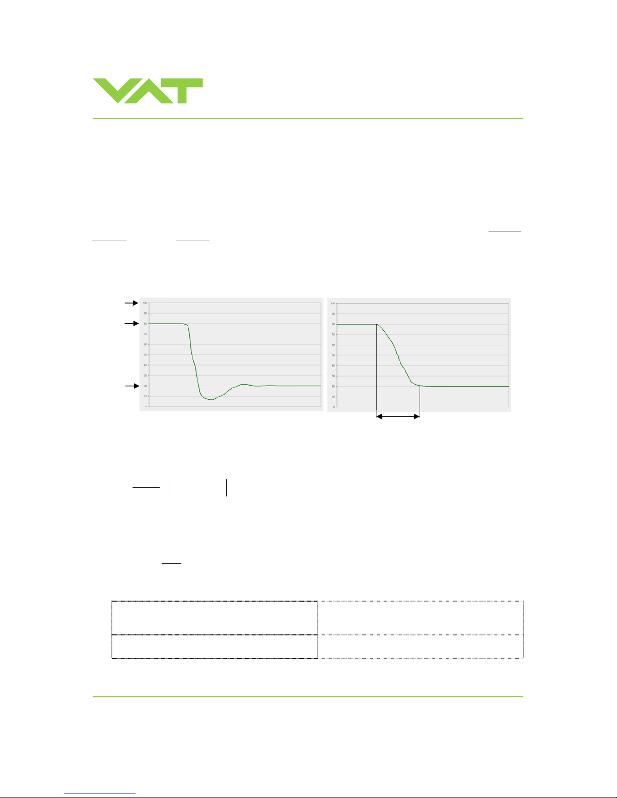
This parameter affects the time that is used to decrease / raise pressure between 2 setpoints. Especially in pressur e
decrease situations at low flows pressure response can be improved much by adapting setpoint ramp time.
Pressure chart
Choose the applicable formula depending on units you are familiar with.
ENDSTART
SFS
RAMP
PP
P
S
t
−
•=
t ramptime [s]
P
SFS
sensor full scale pressure
S
RAMP
setpoint ramp [s]
P
START
pressure start
P
END
pressure end
Adjustment procedure:
1. Start with optimal gain factor and sensor delay time according to preceding tuning steps.
2. Control a typical pressure / flow situat ion.
3. Control a lower
pressure.
4. Repeat from step 2 with longer setpoint ramps until best r e sponse is achi eved.
5. Verify pressure control response for a setpoint raise situation.
Local operation:
(‘Control View’, ‘Control Performance Analyzer’ or
‘Service Box 2‘)
Remote operation:
Do configuration in menu ‘Setup / Control Parameter’.
Note: It’s not possible to do ‘Interface configuration‘
via remote operation.
P
START
P
SFS
t
P
END
Without setpoint ramp optimizing
With setpoint ramp optimizing
Page 28
Installation, Oper ating & Maintenance Instructions
Series 651 DN 320-400 (I.D. 12“ - 16”), Logic
VAT Vakuumventile AG, CH-9469 Haag, Switzerland
Tel +41 81 771 61 61 Fax +41 81 771 48 30 [email protected] www.vatvalve.com
267736ED
2008-02-26
28/53
3.10.2.4 Valve speed adjustment
Valve speed effects:
• Response time
Default value is 1000. Adjustment range is from 1 to 1000.
This parameter effects valve plate actuating speed.
Speed adjustment is effective for PRESSURE CONTROL and POSITION CONTROL.
Note: Normally best pressure control response is achieved with max. valve speed. In particular applications it may be of
advantage to have a slower valve r esponse.
Note: OPEN and CLOSE are always done with max. speed.
Adjustment procedure:
1. Use optimal gain factor, sensor delay time and setpoint ramp according to preceding tuning steps.
2. Open valve.
3. Control a typical pressure / flow situation.
4. Repeat from step 2 with slower valve speed until required response is achieved.
Local operation:
(‘Control View’, ‘Control Performance Analyzer’ or
‘Service Box 2‘)
Remote operation:
Do configuration in menu ‘Setup / Control Parameter’.
Note: It’s not possible to do ‘Interface configuration‘
via remote operation.
3.11 Logic interface
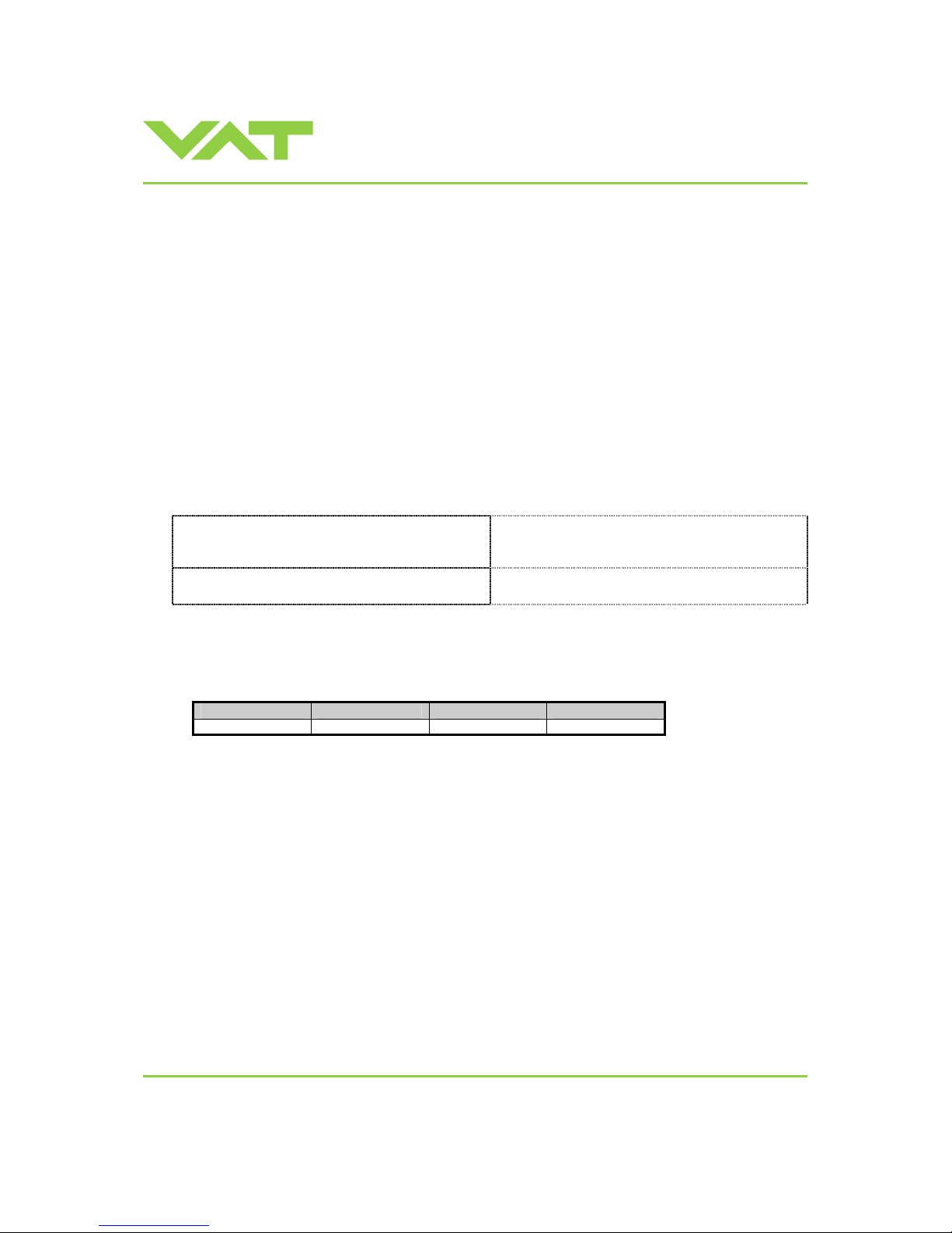
Default configuration:
OPEN input CLOSE input OPEN output CLOSE output
not inverted not inverted open close
Page 29
Installation, Oper ating & Maintenance Instructions
Series 651 DN 320-400 (I.D. 12“ - 16”), Logic
VAT Vakuumventile AG, CH-9469 Haag, Switzerland
Tel +41 81 771 61 61 Fax +41 81 771 48 30 [email protected] www.vatvalve.com
267736ED
2008-02-26
29/53
3.11.1 Functions and Wiring
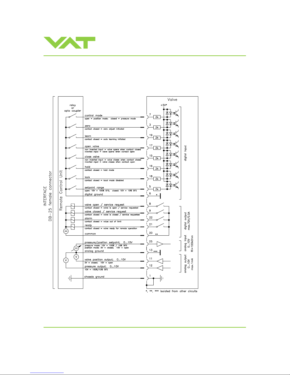
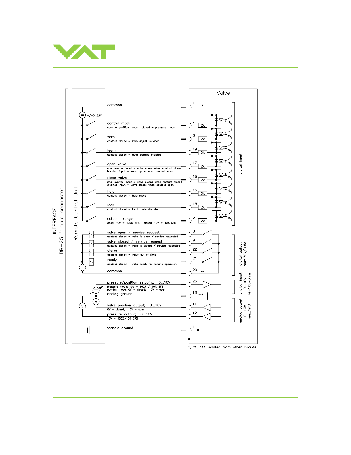
Logic interface allows for remote operation by means of digital and analog signals. Digital inputs may be operated either
by switches or by voltage sources.
a) Configuration with switches for digital inputs:
Note: Use a shielded cable for analog inputs. Do not connect other pins t han indi cated above!
Connector: Use only screws with 4-40UNC thread for fastening the DB-25 connector!
Page 30
Installation, Oper ating & Maintenance Instructions
Series 651 DN 320-400 (I.D. 12“ - 16”), Logic
VAT Vakuumventile AG, CH-9469 Haag, Switzerland
Tel +41 81 771 61 61 Fax +41 81 771 48 30 [email protected] www.vatvalve.com
267736ED
2008-02-26
30/53
b) Configuration with volt age source for digital inputs:
Note: Use a shielded cable for analog inputs. Do not connect other pins t han indi cated above!
Connector: Use only screws with 4-40UNC thread for fastening the DB-25 connector!
Page 31
Installation, Oper ating & Maintenance Instructions
Series 651 DN 320-400 (I.D. 12“ - 16”), Logic
VAT Vakuumventile AG, CH-9469 Haag, Switzerland
Tel +41 81 771 61 61 Fax +41 81 771 48 30 [email protected] www.vatvalve.com
267736ED
2008-02-26
31/53
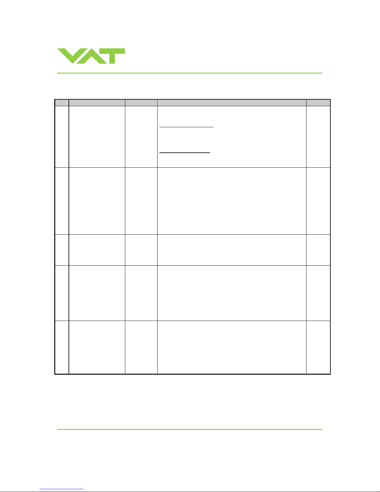
3.11.2 Digital inputs
Pin Function Signal type Description Priority
7 CONTROL MODE
Digital
Input
1)
This pin selects the control mode. This valve may either be
operated as pressure controller or as position controller.
PRESSURE CONTROL is activated as long as optocoupler is
‘on’.
The PID controller controls the chamber pr essure according to
the pressure SETPOINT by means of the valve position.
POSITION CONTROL is activated when optocoupler is ‘off’.
The valve position is directly contr olled according to the
position SETPOINT.
6 2)
5
SETPOINT RANGE
Digital
input
1)
This pin selects the SETPOINT RANGE. Low range extension
is activated as long as optocoupler is ‘on’. It’s effective in
pressure control mode only.
This function extends the lower 10% range of sensor full scale
(SFS) to the full 0-10V for SET P OINT input. Herewith you can
achieve better resolution, especially in case of a 2 sensor
system.
Example with SFS = 100mTorr:
Not active (10V=100%) >> 10V setpoint = 100mTorr
Active (10V=10%): >> 10V setpoint = 10mTorr
N/A
16
HOLD
Digital
input
1)
This function stops the valve at th e current position. After
release of the signal the valve will return to the selected
CONTROL MODE.
This function is activated as long as optocoupler is ‘on’.
5 2)
17
OPEN VALVE
Digital
input
1)
This function will open the valve.
This function is activated as long as optocoupler is ‘on’ in non
inverted configuration.
This function is activated as long as optocoupler is ‘off ’ in
inverted configuration.
Configuration can be done in local operation via service port.
Default settings is not inverted
3 2)
15
CLOSE VALVE
Digital
input
1)
This function will close the valve.
This function is activated as long as optocoupler is ‘on’ in non
inverted configuration.
This function is activated as long as optocoupler is ‘off ’ in
inverted configuration.
Configuration can be done in local operation via service port.
Default settings is not inverted
2 2)
1) All digital inputs are digitally filtered. Filter delay is 50ms. This means that digital signals must be applied for
at least 50ms to be effective. Refer to «Function and wiring» for details about input circuit.
2) Highest priority is 1. Functions with lower priorities will not be effective as long as higher priority functions
are active.
Page 32

Installation, Oper ating & Maintenance Instructions
Series 651 DN 320-400 (I.D. 12“ - 16”), Logic
VAT Vakuumventile AG, CH-9469 Haag, Switzerland
Tel +41 81 771 61 61 Fax +41 81 771 48 30 [email protected] www.vatvalve.com
267736ED
2008-02-26
32/53
Pin Function Signal type Description Priority
3
ZERO
Digital
Input
1)
This function compensates the pressure gauge offset voltage
and sets the pressure value to zero. In case of a 2 sensor
system both sensor inputs will be adjusted.
This function is initiated by th e ‘off’ to ‘on’ transition of the
optocoupler.
If ‘on’ remains established this will not re-i nit iate the function
and does also not block functions with lower priorities.
Note: Do not perform ZERO as long as pressure gauge voltage
is shifting.
Note: Do not perform ZERO, if the base pressure of your
vacuum system is higher than 1%o of sensor full scale. We
recommend disabling ZERO function in this case. You can
disable the function in local operation via service po rt.
1 2)
19
LEARN
Digital
Input
1)
The LEARN routine determines the control characteristic of the
vacuum system.
This function is initiated by th e ‘off’ to ‘on’ transition of the
optocoupler. A transition from ‘on’ to ‘off’ while the routine is
running would stop it.
While running, the routine may not be interrupted by another
function with higher priority. If ‘on’ remains established after
completion this will not re-initiate the function and does also not
block functions with lower priorities.
Note: Without a LEARN data set the PID controller is not able
to perform pressure control.
4 2)
18 LOCK
Digital
input
1)
This function locks the valve in remote op eration. In case the
valve is in local operation it will turn to remote operation. Local
operation via service port is not possible wh en LO CK is
activated.
When the signal is released the valve remains in remote
operation but local operation may be activat ed via service port.
N/A
6
DIGITAL GROU ND
Digital
ground
Ground for all digital inputs. Ground is used whe n digital inputs
are operated by switches. Connect switches to ground.
Refer also to «Function and wiring» configuration a).
4
DIGITAL COMMON
Digital
common
Common for all digital inputs. Common is used when digital
inputs are driven by voltage sources. Connect + or – terminal of
source with common (input optocouplers are capable of
bidirectional operation).
Refer also to «Function and wiring» configuration b).
1) All digital inputs are digitally filtered. Filter delay is 50ms. This means that digital signals must be applied for
at least 50ms to be effective. Re fer to «Function and wiring» for details about input circuit.
2) Highest priority is 1. Functions with lower priorities will not be effective as long as higher priority functions
are active.
Page 33
Installation, Oper ating & Maintenance Instructions
Series 651 DN 320-400 (I.D. 12“ - 16”), Logic
VAT Vakuumventile AG, CH-9469 Haag, Switzerland
Tel +41 81 771 61 61 Fax +41 81 771 48 30 [email protected] www.vatvalve.com
267736ED
2008-02-26
33/53
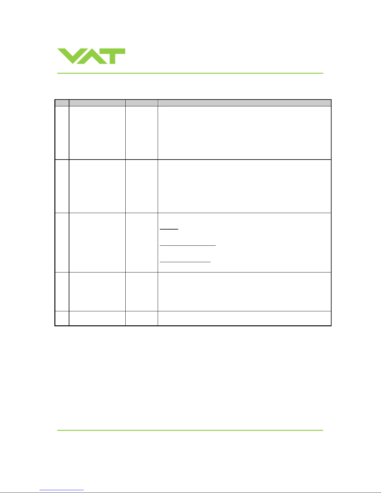
3.11.3 Digital outputs
Pin Function Signal type Description
8
VALVE OPEN
SERVICE REQUEST
Digital
output
1)
This output is active in all operation modes and indicates either that the
valve is open or that a service is requested.
A service request is indicated when the valve requires cleaning due to
contamination.
Configuration of the functionality of this output can be done in local
operation via service port.
By default the output indicates open
9
VALVE CLOSED
SERVICE REQUEST
Digital
output
1)
This output is active in all operation modes and indicates either that the
valve is close or that a service is requested.
A service request is indicated when the valve requires cleaning due to
contamination.
Configuration of the functionality of this output can be done in local
operation via service port.
By default the output indicates close
22
ALARM
Digital
output
1)
The meaning of the alarm output depends on the operation mode.
LEARN:
LEARN is not completed yet.
PRESSURE CONTROL:
Actual pressure is out of ±2% range of SETPOINT
POSTION CONTROL :
Actual position is out of ±0.1% range of SETPOINT
21 READY
Digital
output
1)
This signal indicates that the valve is ready for remote operation.
If this signal is not active the valve is in one of the followi ng modes:
• Synchronization during power up
• Local operation via service port
• Safety mode. Refer to «Safety mode» fo r details.
20
COMMON
Digital
common
Common for all digital outputs.
1) Refer to «Function and wiring» for details about output circui t.
Page 34
Installation, Oper ating & Maintenance Instructions
Series 651 DN 320-400 (I.D. 12“ - 16”), Logic
VAT Vakuumventile AG, CH-9469 Haag, Switzerland
Tel +41 81 771 61 61 Fax +41 81 771 48 30 [email protected] www.vatvalve.com
267736ED
2008-02-26
34/53
3.11.4 Analog inputs and outputs
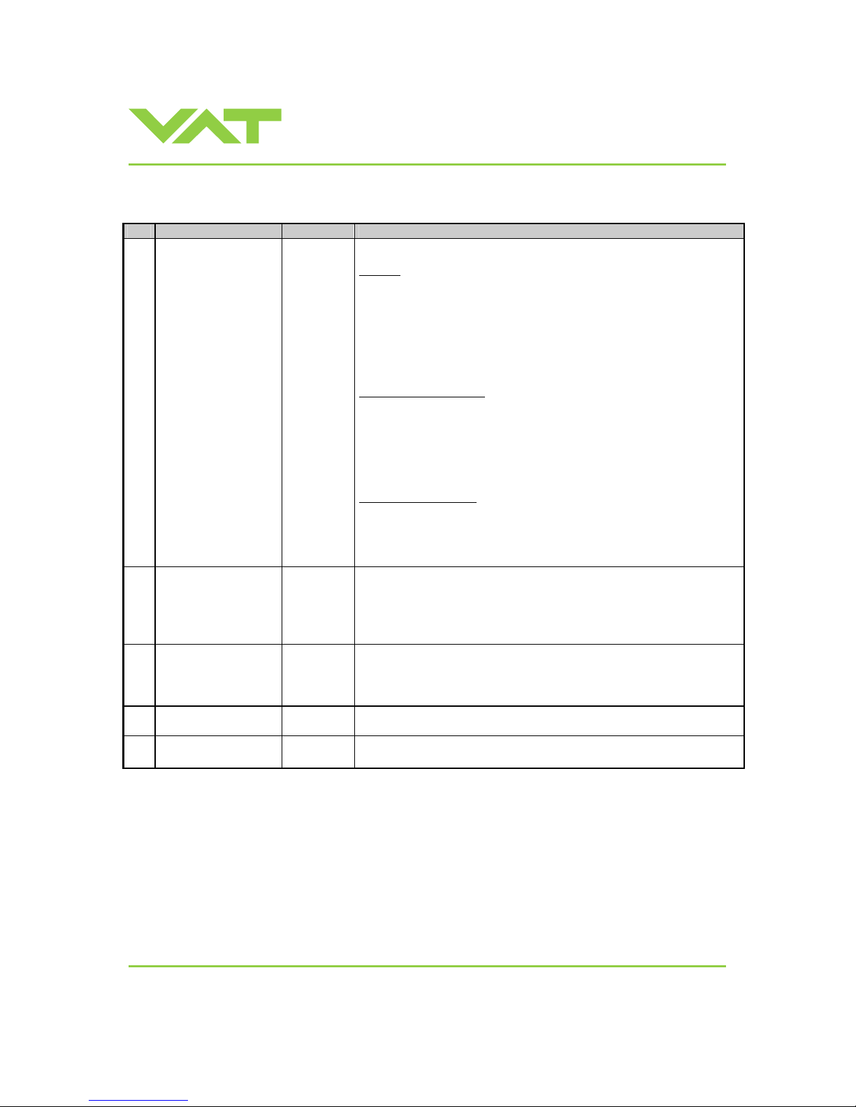
Pin Function Signal type Description
25
SETPOINT
Analog
input
1)
The meaning of the setpoint input depends on the operation mode.
LEARN:
A voltage of 0-
10V shall be applied to this input as pressure limit for learn.
The limit pressure is in linear relation to the applied voltage. 10V relates to
sensor full scale.
In case of 2 sensor operation 10V relates to sensor 1 full scale (high
range).
Note: To activate pressure limit function for remote operation it must be
configured accordingly. Refer to «Inter face configuration»
PRESSURE CONTROL:
A voltage of 0-10V shall be applied to this input as pressure setpoint. The
pressure setpoint is in linear relation to the applied voltage. Depending on
selected SETPOINT RANGE 10V means either sensor full scale or 10%
of sensor full scale.
In case of 2 sensor operation 10V relates to sensor 1 full scale (high
range).
POSITION CONTROL:
A voltage of 0-10V shall be applied to this input as position setpoint. T he
position setpoint is in linear relation to the applied voltage. 0V is closed
but not isolation function and 10V is open position.
(Use digital input for isolation function)
12 PRESSURE
Analog
output
1)
This output indicates the current pressure as 0-10V. The output voltage is
in linear relation to the pressure. Depending on the selected SETPOINT
RANGE 10V means either sensor full scale or 10% of sensor full scale.
In case of 2 sensor operation sensor full scale relates to sensor 1 (high
range).
11 POSITION
Analog
output
1)
This output indicates the current valve position as 0-10V voltage range.
The voltage is in linear relation to the valve position. 0V is closed but not
isolation function and 10V is open position.
(Use digital output for isolation function)
13
ANALO G G ROUND
Analog
ground
Ground for analog input and analog outputs.
1 CHASSIS GROUND
Chassis
ground
Chassis ground connected to case. Shall be used to connect cable shield.
1) Refer to «Function and wiring» for details about input / output circuit.
Page 35
Installation, Oper ating & Maintenance Instructions
Series 651 DN 320-400 (I.D. 12“ - 16”), Logic
VAT Vakuumventile AG, CH-9469 Haag, Switzerland
Tel +41 81 771 61 61 Fax +41 81 771 48 30 [email protected] www.vatvalve.com
267736ED
2008-02-26
35/53
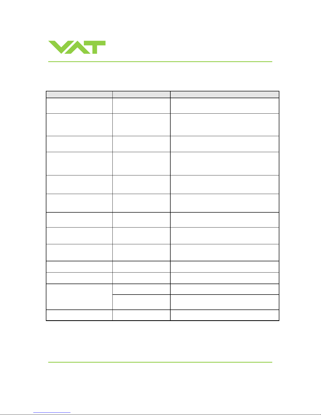
4 Trouble shooting
Failure Check Action
No dots lighted on display
- 24 V power supply ok? - Connect valve to power supply according to
«Electrical connection» and make sure that power supply
is working.
- Local operation via service
port active
- Switch to remote operation.
Remote operation does not work
- Safety mode active, check for
D on display?
- Provide power to motor to allow for operation.
- Refer to «Electrical connection» for details.
Display shows «E 20»
(fatal error - limit stop of valve
unit not detected)
- Replace actuator according to
«Maintenance procedures».
Display shows «E 22»
(fatal error - rotation angle of
valve plate limited during
operation)
- Valve plate mechanically
obstructed?
- Resolve obstruction.
Display shows «E 40»
(fatal error - motor driver failure
detected)
- Replac e cont rol unit ac cordi ng to
«Maintenance procedures».
Display shows «D C» or
«D999»
Motor Interlock is open
- Motor power supplied? - Provide power to motor to allow for operation.
- Refer to «Electrical connection» for details.
Display shows «SR»
(Service Request)
- Valve unit heavy
contaminated or gate seal
heavyly sticking?
- Clean valve and/or replace gate seal according to
«Maintenance procedures».
CLOSE VALVE does not work
- Safety mode active, check for
D on display?
- Maintenance mode active
- Provide power to motor to allow for operation.
- Refer to «Electrical connection» for details.
- Refer to “Display shows «
M C»” in this table
OPEN VALVE does not work
- Safety mode active, check for
D on display?
- Maintenance mode active
- Provide power to motor to allow for operation.
- Refer to «Electrical connection» for details.
- Refer to “Display shows «
M100»” in this table
Display shows «M C»
Maintenance mode active
- Pin 14 of service connector is connected to ground. Plate
will close. Further movement of plat e is bloc k ed .
1)
Display shows «M100»
Maintenance mode active
- Pin 13 of service connector is connected to ground. Plate
will open. Further movement of plate is blocked.
1)
- Safety mode active, check for
D on display?
- Provide power to motor to allow for operation.
- Refer to «Electrical connection» for details.
POSITION CONTROL does not
work
- POSITION CONTROL
selected, check for V on
display?
- Sel ec t POS IT I ON CONTROL mode.
Refer to «Position control» for details.
COMPRESSED AIR FAILURE
- No or too less air pressure on
air input of valve
- Connect ai r or increase air pressur e. Make sure that the air
pressure is more than 4 bar (55 psi).
1)Priority of pin 14 is higher than pin 13. If pin 14 is connected to ground after pin 13 the valve will clos e.
Ground of service connector is at pin 4 and 8.
Page 36

Installation, Oper ating & Maintenance Instructions
Series 651 DN 320-400 (I.D. 12“ - 16”), Logic
VAT Vakuumventile AG, CH-9469 Haag, Switzerland
Tel +41 81 771 61 61 Fax +41 81 771 48 30 [email protected] www.vatvalve.com
267736ED
2008-02-26
36/53
Failure Check Action
- Sensor(s) connected? - Refer to «Electrical connection».
- 2 sensor version present at
valve controller?
- Check valve version on page 1. Verify confi gurat ion. Refer
to «Setup procedure».
- ZERO done? - Perform ZERO when base pressure is reached. Refer to
«ZERO» for details.
Pressure reading is wrong
or
pressure reading is negative
- Does sensor power supply
provide enough power for
sensor(s)?
- Verify sensor supply voltage.
- Valve in open position, check
for O on display?
- OP EN VA LVE and bring cham ber to bas e press ure before
performing ZERO.
ZERO does not work
- ZERO disabled? - Enable ZERO.
Refer to «Valve and sensor configuration» for details.
- Sensor voltage shifting? - Wait until sensor does not shift any more before
performing ZERO.
- System pumped to base
pressure?
- OP EN VA LVE and bring cham ber to bas e press ure before
performing ZERO.
Pressure is not ‘0’ after ZERO
- Sensor offset voltage
exceeds ±1.4V
- Replace pressure gauge.
- Safety mode active, check for
D on display?
- Provide power to motor to allow for operation.
- Refer to «Electrical connection» for details.
- PRESSURE CONTROL
selected, check for P on
display?
- Select PRESSURE CONTROL mode.
Refer to «Pressure control» for details.
PRESSURE CONTROL does
not work
- LEARN done? - Perform LEARN.
Refer to «Setup procedure» for details.
- Setup done completely? - Perform «Setup procedure» completely.
- LEARN done? - Perform LEARN.
Refer to «LEARN» for details.
- ZERO performed before
LEARN?
- Perf orm ZERO then repeat LEA RN.
Refer to «Setup procedure» for details.
- LEARN interrupted? - Repeat LEARN.
Refer to «LEARN» for details.
- Was gas flow stable during
LEARN?
- Repeat LEARN with stable gas flow.
Refer to «LEARN» for details.
- Tuning done? - Tune valve for appli c ati on.
- Refer to «Tuning of control performance» for details.
- Is sensor range suited for
application?
- Use a sensor with suit able range (cont rolled press u re
should be >3% and < 98% of sensor full scale).
PRESSURE CONTROL not
optimal
- Noise on sensor signal? - Make sure a shiel ded sens or cable i s used.
If you need any further information, please contact one of our service centers. You can find the addresses on our website:
http://www.vat.ch
Page 37
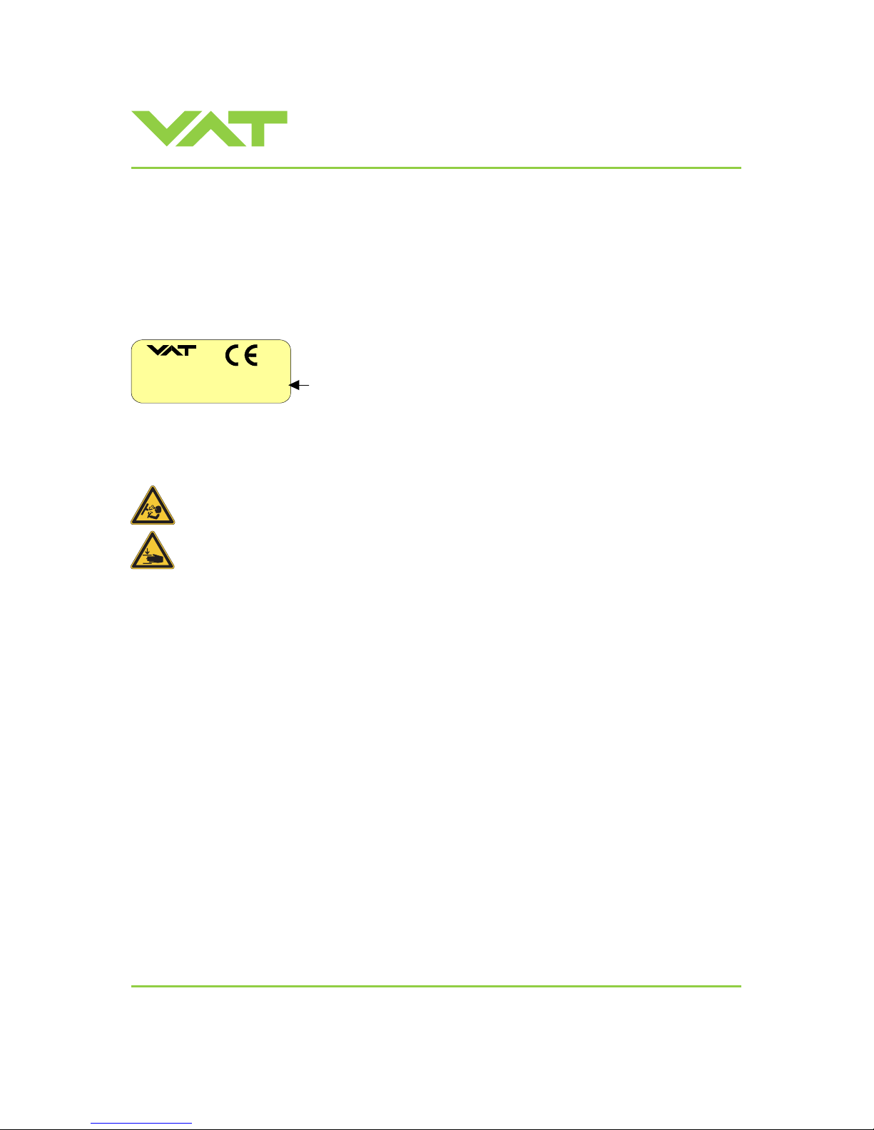
Installation, Oper ating & Maintenance Instructions
Series 651 DN 320-400 (I.D. 12“ - 16”), Logic
VAT Vakuumventile AG, CH-9469 Haag, Switzerland
Tel +41 81 771 61 61 Fax +41 81 771 48 30 [email protected] www.vatvalve.com
267736ED
2008-02-26
37/53
5 Maintenance & r epairs
Under clean operating conditions, the valve does not requir e any maintenance during the specified cycle life.
Contamination from the process may influence the function and requir es more fr equent maintenance.
Before carrying out any maintenance or repairs, please contact VAT. It has to be individually decided w hether the
maintenance/repair can be performed by the customer or has to be carried out by VAT. The fabr ication number on the
valve
made in Switzerland
Fabrication No.: patented
. .
. . . . . – . . . . – . . . . / . . . .
A
– . . . . . .
Fabrication number
has always to be specified.
All supplies (e. g. compressed air, electrical power) must be disconnected for removal/installation of the valve from/into
the system.
Even with disconnected supply, loaded springs and/or air cushions in cylinders can be potential hazards.
Keep fingers and objects away from the v alve opening!
Products returned to VAT must be free of harmful substances such as e.g. toxical, caustic or micro-biological ones. If
products are radioactively contaminated, fill in the VAT form «Contamination and Radiation Report» and send it with the
product. The form is available at VAT. The maximum values indicated in the form must not be exceeded.
Page 38
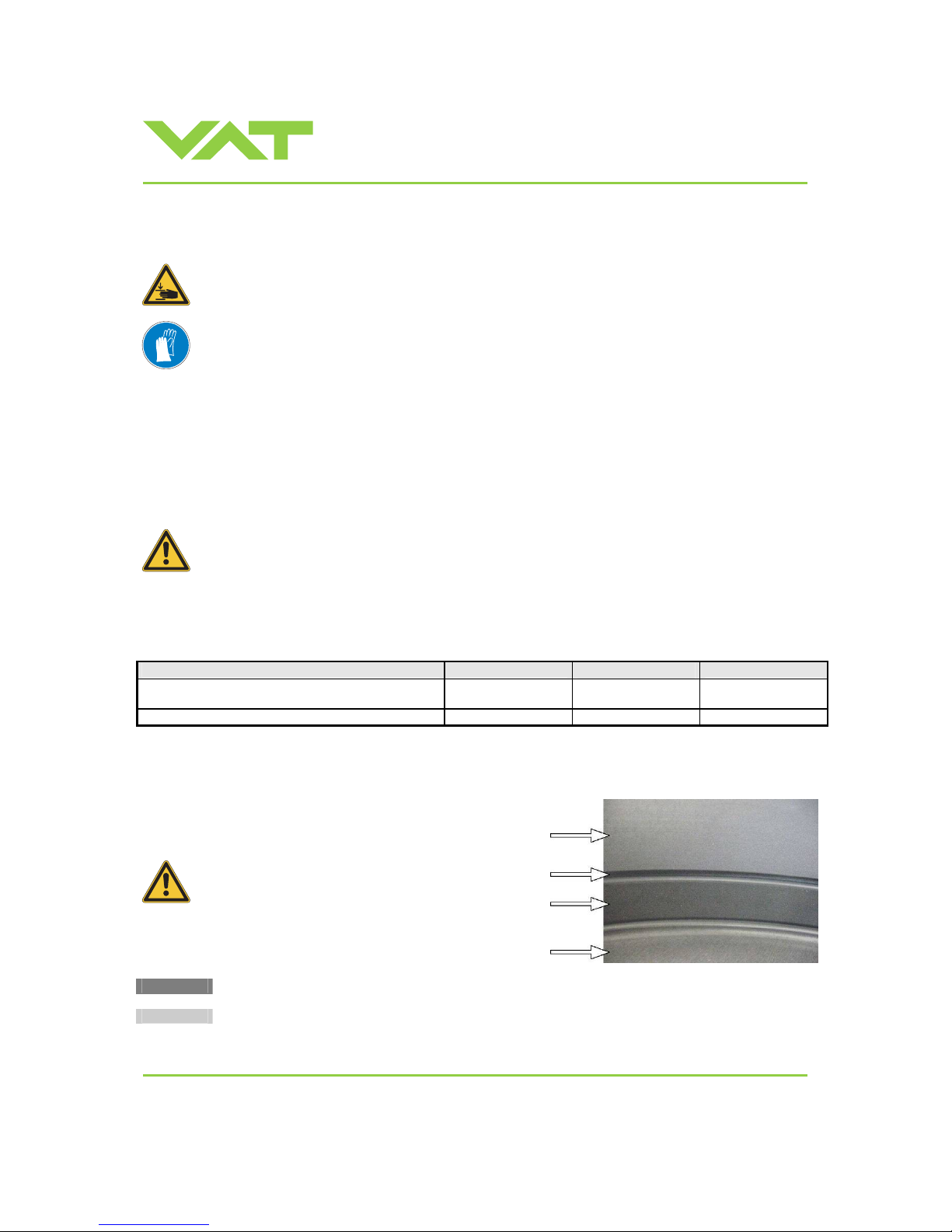
Installation, Oper ating & Maintenance Instructions
Series 651 DN 320-400 (I.D. 12“ - 16”), Logic
VAT Vakuumventile AG, CH-9469 Haag, Switzerland
Tel +41 81 771 61 61 Fax +41 81 771 48 30 [email protected] www.vatvalve.com
267736ED
2008-02-26
38/53
5.1 Maintenance procedures
Keep fingers out of the valve during maintenance work.
Use cleanroom gloves during maintenance work.
Two preventive maint enance procedures are defined for this valve. These are:
• Replacement of isolation seals (gate and body seal of sealing ring) and valve cleaning
• Replacement of actuator or actuator shaft seals
Required frequency of cleaning and replacement of seals is depending on process conditions.
A critical factor influencing the maintenance period is the lifetime of the vacuum grease, being limited under
increased temperature. In this case grease will separate to PTFE and oil. The oil may flow and contaminate
the valve parts.
VAT can give the following recommendatio ns for preventive maintenance:
unheated *)
heated ≤ 80°C *)
heated > 80°C *)
isolation seals (gate and body seal of sealing ring)
200’000 cycles 6 months but
max. 200’000 cycles
3 months but
max. 200’000 cycles
actuator shaft seals
1’000’000 cycles 6 months 3 months
*) This figures are reference values for clean conditions under various temperatures. These values do not include any
impact of the process. Therefore preventive maintenance schedule has finally to be checked for the actual process
conditions.
Prevent gap between body and sealing
ring from air gun cleaning. Otherwise
vacuum grease may be distributed and
contaminate the valve.
valve body
gap
sealing ring
pendulum plate
Replacement of isolation seals (gate and body seal of sealing ring) and valve cleaning
Replacement of actuator or actuatorshaft seals
Page 39
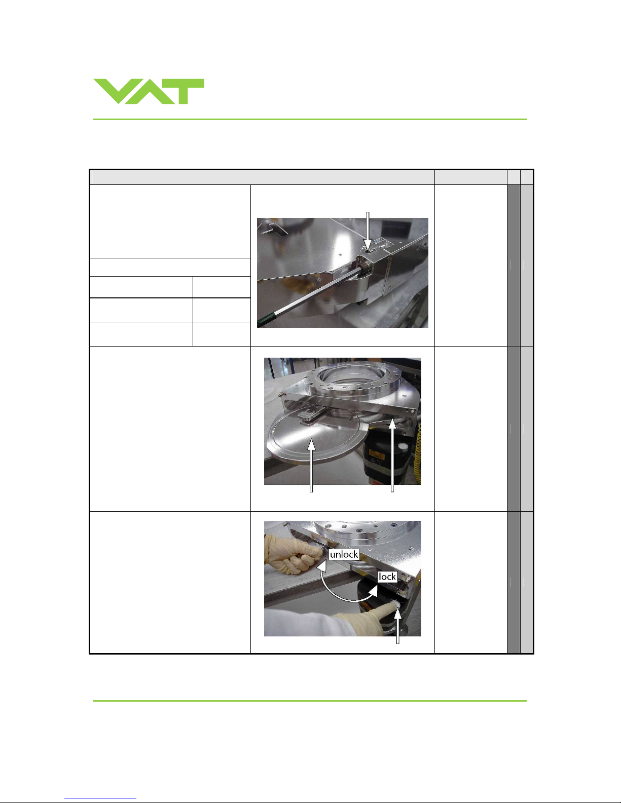
Installation, Oper ating & Maintenance Instructions
Series 651 DN 320-400 (I.D. 12“ - 16”), Logic
VAT Vakuumventile AG, CH-9469 Haag, Switzerland
Tel +41 81 771 61 61 Fax +41 81 771 48 30 [email protected] www.vatvalve.com
267736ED
2008-02-26
39/53
Note: Electrical power and compre ssed air is required to perform steps 2 to 9 during disassembly respectiv e ly 9 to 2
during assembly.
D e s c r i p t i o n Required tool
1. Vent both valve chambers.
2. Open bonnet screws. Press snap in
fixation on one side and pull bonnet
a little bit on that side. Than press
snap in fixation on other side and
remove valve bonnet.
Caution:
Weight of valve bonnet is approx.
DN320 / 12”
(65150 - . . . . - . . . .)
13.0 kg
DN350 / 14”
(65151 - . . . . - . . . .)
15.0 kg
DN400 / 16”
(65152 - . . . . - . . . .)
18.0 kg
snap in fixation
Allen wrench
8mm
3. Open valve
Caution: Stand away from valve –
pendulum plate moves out of the
valve body.
4. Unfasten mounting screw for
pendulum plate.
5. Remove pendulum plate.
pendulum plate mounting screw
for pendulum plate
open end wrench
13mm
6. With one hand press the
MAINTENANCE BUTTON to lower
the sealing ring, with your second
hand unlock the sealing ring by
pressing the handle.
7. Release MAINTENANCE BUTTON.
8. Remove sealing ring.
9. To prevent the shaft and retaining
pins from moving during work, swi tch
the valve to safety mode. Refer to
«Safety mode» for details.
Note: Retaining pins will move up.
maintenance button
Page 40
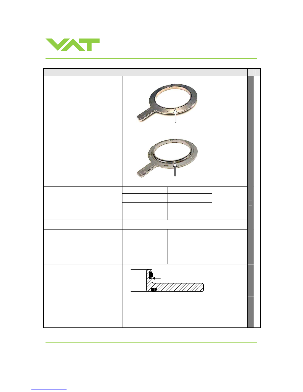
Installation, Oper ating & Maintenance Instructions
Series 651 DN 320-400 (I.D. 12“ - 16”), Logic
VAT Vakuumventile AG, CH-9469 Haag, Switzerland
Tel +41 81 771 61 61 Fax +41 81 771 48 30 [email protected] www.vatvalve.com
267736ED
2008-02-26
40/53
D e s c r i p t i o n Required tool
gate seal
10. Remove gate and body o-ring from
sealing ring carefully with a soft tool.
11. Remove grease residues at sealing
ring with alcohol.
Clean sealing ring and pendulum
plate with alcohol or in an ultrasonic
bath.
12. Clean out valve body with al cohol.
Use an appropriate non metal tool
with a cloth to enter valve body.
Do not enter valve body with hands!
Then blow out valve body with clean
air.
Do not directly expose seals
(actuator and retaining pin
feedthroughs) to air stream!
13. Clean or replace gate seal if
necessary.
Install gate o-ring to sealing ring
without grease.
body seal
Valve size Quantity of grease [m l ]
DN320 / 12”
(65150 - . . . . - . . . .)
0.3
DN350 / 14”
(65151 - . . . . - . . . .)
0.4
14. Clean or replace body seal if
necessary.
Lubricate body o-ring with the
quantity of vacuum grease listed in
the table to the right.
DN400 / 16”
(65152 - . . . . - . . . .)
0.4
15. Install body o-ring into sealing ring.
Valve size Quantity of grease [ml]
DN320 / 12”
(65150 - . . . . - . . . .)
0.5
DN350 / 14”
(65151 - . . . . - . . . .)
0.7
16. Deposit vacuum grease on the
bottom side of the body seal
according to drawing below. Pay
attention that the quantity of vacuum
grease listed in the table to the right
is distributed constantly over the
whole circumference.
DN400 / 16”
(65152 - . . . . - . . . .)
1.1
Note: For Replacement of actuator
or actuator shaft seals, proceed with
step 18 otherwise go to step 17.
17. Reassembly the valve in reverse
order, step 9…3.
18. Close the valve bonnet, see step 40.
Apply grease deposit
on this side
Page 41
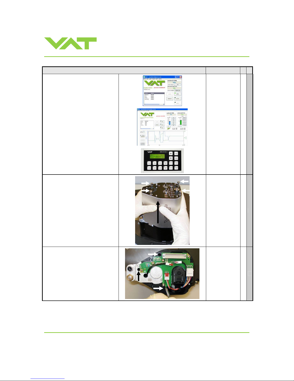
Installation, Oper ating & Maintenance Instructions
Series 651 DN 320-400 (I.D. 12“ - 16”), Logic
VAT Vakuumventile AG, CH-9469 Haag, Switzerland
Tel +41 81 771 61 61 Fax +41 81 771 48 30 [email protected] www.vatvalve.com
267736ED
2008-02-26
41/53
D e s c r i p t i o n Required tool
19. Release the valve from safety mode.
Refer to «Safety mode» for details
20. Move the valve to positio n 50% ( half
opened) This is necessary, in order
to dismount the actuator. See step
24.
21. Disable PFO option feature via
'Power Fail Status' in menu 'System'
of CV or CPA software, and turn off
the power
• CV software
• CPA software
or
• Service Box 2
22. Di sconnect 24VDC power. Wait for
60s, then disconnect cable and
compressed air from valve actuator.
23. Unfasten all 4 controller screws and
lift controller carefully from actuator.
Allen Wrench
4 mm
24. Unfasten all 3 actuator screws and
remove actuator.
Allen Wrench
5 mm
Page 42
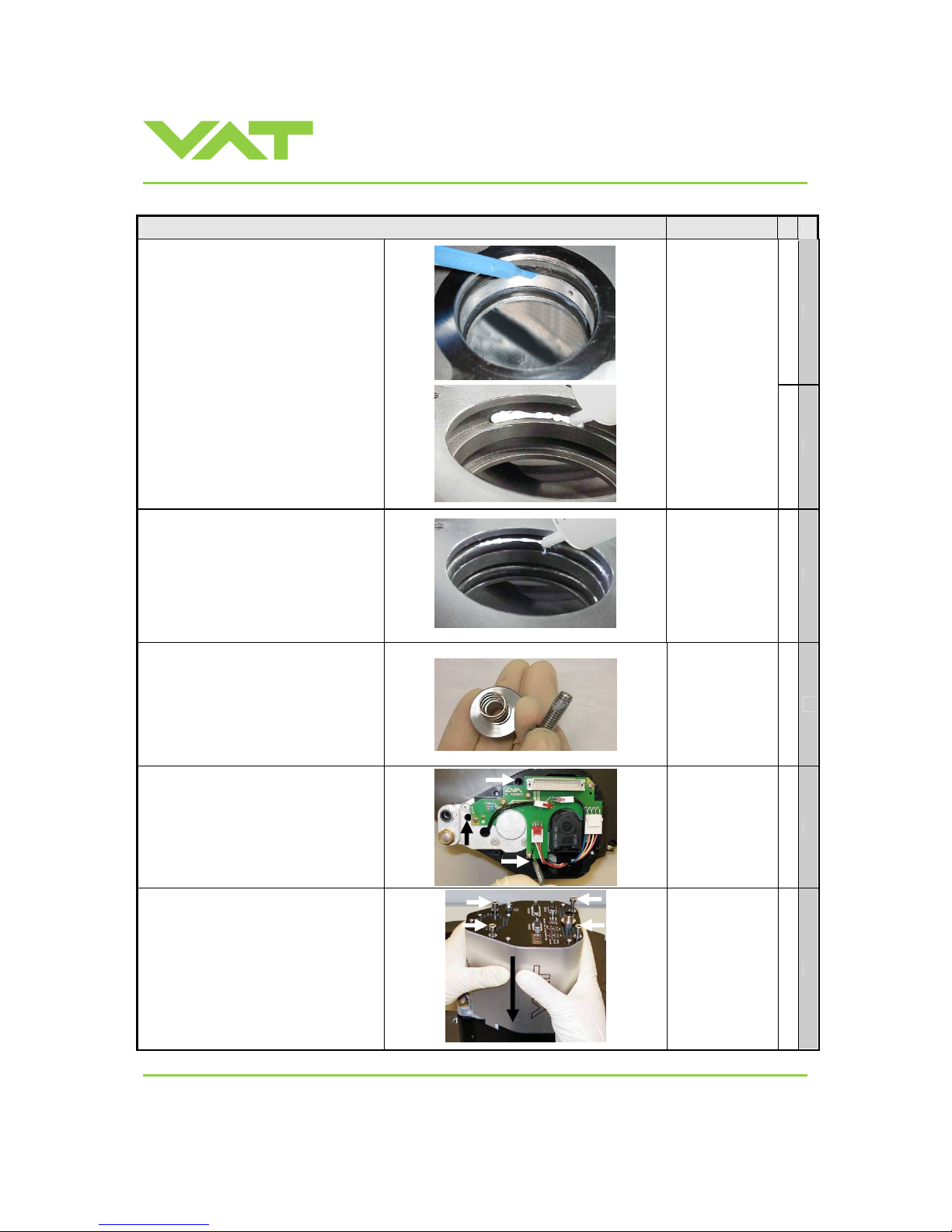
Installation, Oper ating & Maintenance Instructions
Series 651 DN 320-400 (I.D. 12“ - 16”), Logic
VAT Vakuumventile AG, CH-9469 Haag, Switzerland
Tel +41 81 771 61 61 Fax +41 81 771 48 30 [email protected] www.vatvalve.com
267736ED
2008-02-26
42/53
D e s c r i p t i o n Required tool
25. Remove actuator shaft seals
carefully with a soft tool.
26. Cl ean actuator feedthrough with
alcohol.
27. Lubricate each o-ring groove with
0.1 ml vacuum grease. Pay attention
that grease is distributed constantly
over the whole circumference.
• Soft tool
(o-ring remover)
• Vacuum grease
28. Clean or replace seals if necessary.
Lubricate each o-ring with 0.05 ml
vacuum grease.
29. Install o-rings.
30. Deposit 0.1 ml vacuum grease on
each o-ring. Pay attention that
grease is distributed constantly over
the whole circumference.
31. Remove fixation kit and mounting
screw for pendulum plate.
32. Cl ean screw and slightly lubricate
thread with 0.1 ml vacuum grease,
then reinstall fixation kit.
33. Cl ean actuator shaft and lubricate it
with 0.1 ml vacuum grease.
34. Install actuator
• Tighten actuator screws with 6 Nm.
• Remove vacuum grease from
actuator shaft face after installati on.
Allen Wrench
5mm
35. Install controller
• Tighten the controller screws with
1 Nm.
• Connect cables at controller
• Connect compressed air at
actuator
Allen Wrench
4mm
Page 43
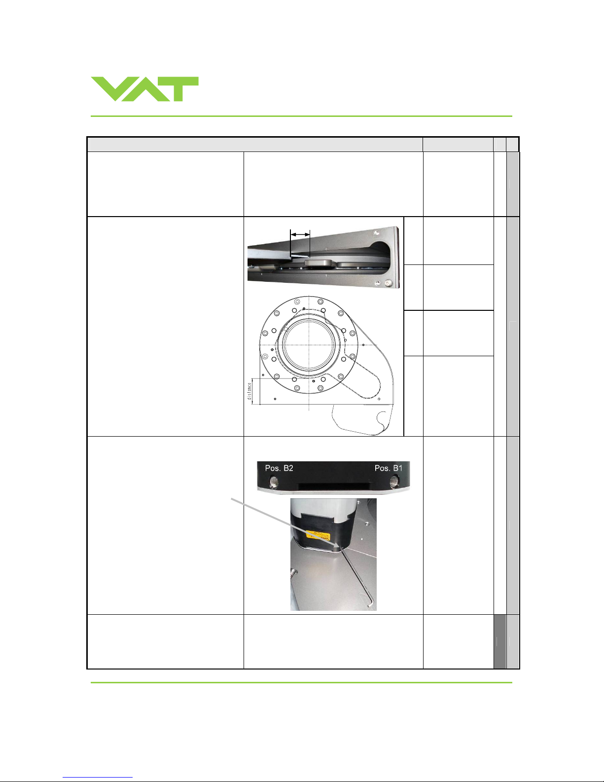
Installation, Oper ating & Maintenance Instructions
Series 651 DN 320-400 (I.D. 12“ - 16”), Logic
VAT Vakuumventile AG, CH-9469 Haag, Switzerland
Tel +41 81 771 61 61 Fax +41 81 771 48 30 [email protected] www.vatvalve.com
267736ED
2008-02-26
43/53
D e s c r i p t i o n Required tool
36. Turn on power of controller.
Note: valve moves to close position.
37. Open valve and install sealing ring
and pendulum plate in reverse order
as they had been disassembled
(steps 9 to 3) .
open end wrench
13mm
DN
Distance D [mm]
between bonnet
flange surface
and pendulum
plate
320
60.5 ±0.5
350
59.0 ±0.5
If actuator was replaced, proceed with
point 38, otherwise go to point 40.
38. Cl ose valve and check if pendulum
plate is in center of flange. Check
can be done either visual or by
measurement.
When the valve is mounted to a tool,
the bonnet has to be removed and
the center position can be measured
by a depth gauge (see picture).
If the centering (or distance) is not
correct, proceed with point 39.
D
400
62.0 ±0.5
39. f necessary adjust pendulum plate:
a. Move pendulum plate a little towards
open (e.g. position 1% of full stroke)
b. Use adjustment screw at flange side
of actuator (1 turn clockwise adjusts
pendulum plate by about 3mm
towards open).
c. Restart valve in menu
‘System/Recovery’
d. Check pendulum plate position
according point 38 38and redo
adjustment procedure if necessary.
Adjusting screw mounted either in actuator
position «B1 standard» or «B2 option»
Allen wrench
3mm
40. Cl ean valve bonnet sealing surface
and o-ring
• Mount valve bonnet, see step 2.
• Tightening torques for bonnet
screws, see in table to the right.
Max. torque 16 Nm
Allen wrench
8mm
Page 44
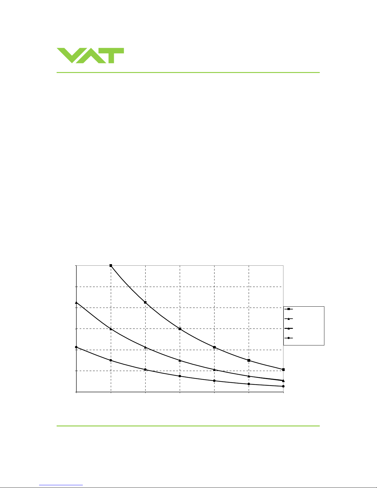
Installation, Oper ating & Maintenance Instructions
Series 651 DN 320-400 (I.D. 12“ - 16”), Logic
VAT Vakuumventile AG, CH-9469 Haag, Switzerland
Tel +41 81 771 61 61 Fax +41 81 771 48 30 [email protected] www.vatvalve.com
267736ED
2008-02-26
44/53
5.2 Option board
The option board may or may not be equipped in your valve depending on the order. Refer to page 1 of this manual to
check valve version. This board includes the optional modules for the valve which are:
• ±15VDC sensor power supply (SPS)
• Power failure option (PFO)
It is available in 3 versions. These are:
• SPS module only
• PFO module only
• SPS and PFO module
The modules may be retrofitted or replaced easily . The battery lifetime of the PFO module depends on the ambient
temperature (see below). T o assu re PFO function the option board must be replaced after battery life has expired.
For ordering number of the modules refer to «Spare parts and accessories».
5.2.1 Durability of power fail battery
The curves in the graph show the estimated life of UltraCap PFO in the worst condition (max. sensor load = 1 A, valve
heating temperature = 150 degree C).
If the SPS is not fully loaded (< 1 A) or heating temperature of valve body is lower than 150 degree C, the corresponding
life time curve will be somewhere in between the upper and the lower curve.
Therefore please determine the equivalent maintenance period for replacing the UltraCap battery (Option board).
0
20
40
60
80
100
120
20 25 30 35 40 45 50
Ambient temperature [°C]
Durability [months]
w/o SPS module,
valve unheated
with SPS module,
valve unheated
w/o SPS module,
valve heated
with SPS module,
valve heated
Note: This graph shows estimated life of UltraCap PFO for reference and not as guaranteed value.
Page 45
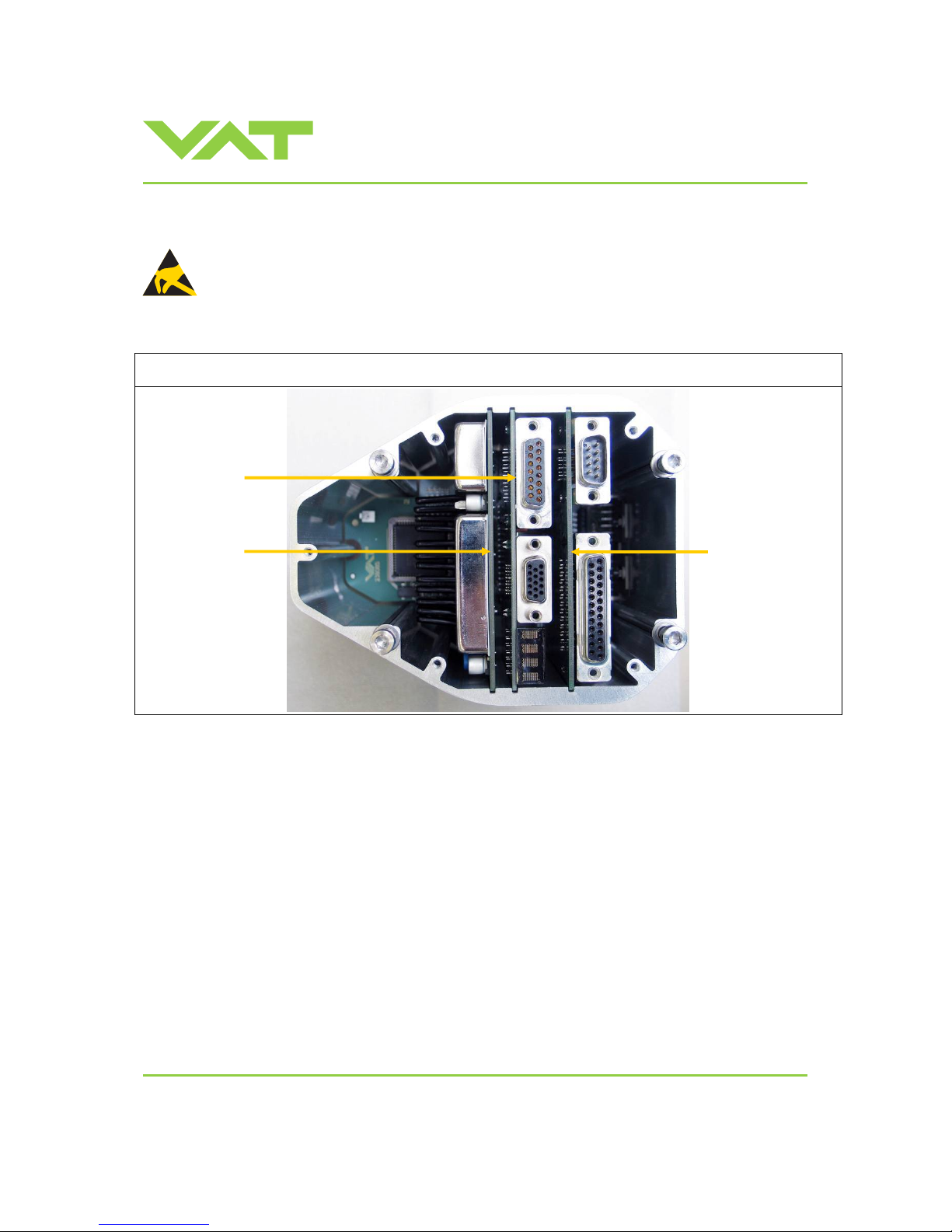
Installation, Oper ating & Maintenance Instructions
Series 651 DN 320-400 (I.D. 12“ - 16”), Logic
VAT Vakuumventile AG, CH-9469 Haag, Switzerland
Tel +41 81 771 61 61 Fax +41 81 771 48 30 [email protected] www.vatvalve.com
267736ED
2008-02-26
45/53
5.2.2 Retrofit / replacement procedure
ESD Precaution!
All work on the control and actuating unit has to be done under ESD protected environment to prevent
electronic components from damage!
Top view on control and actuating unit with panel removed:
Note: All boards have a fixed position int o control and actuating unit. It is not possible to fit a board in other position as
shown in picture above. Do not try out other positions, that may be destroy the socket of boards!
Master board
Option board
Interface board
Page 46
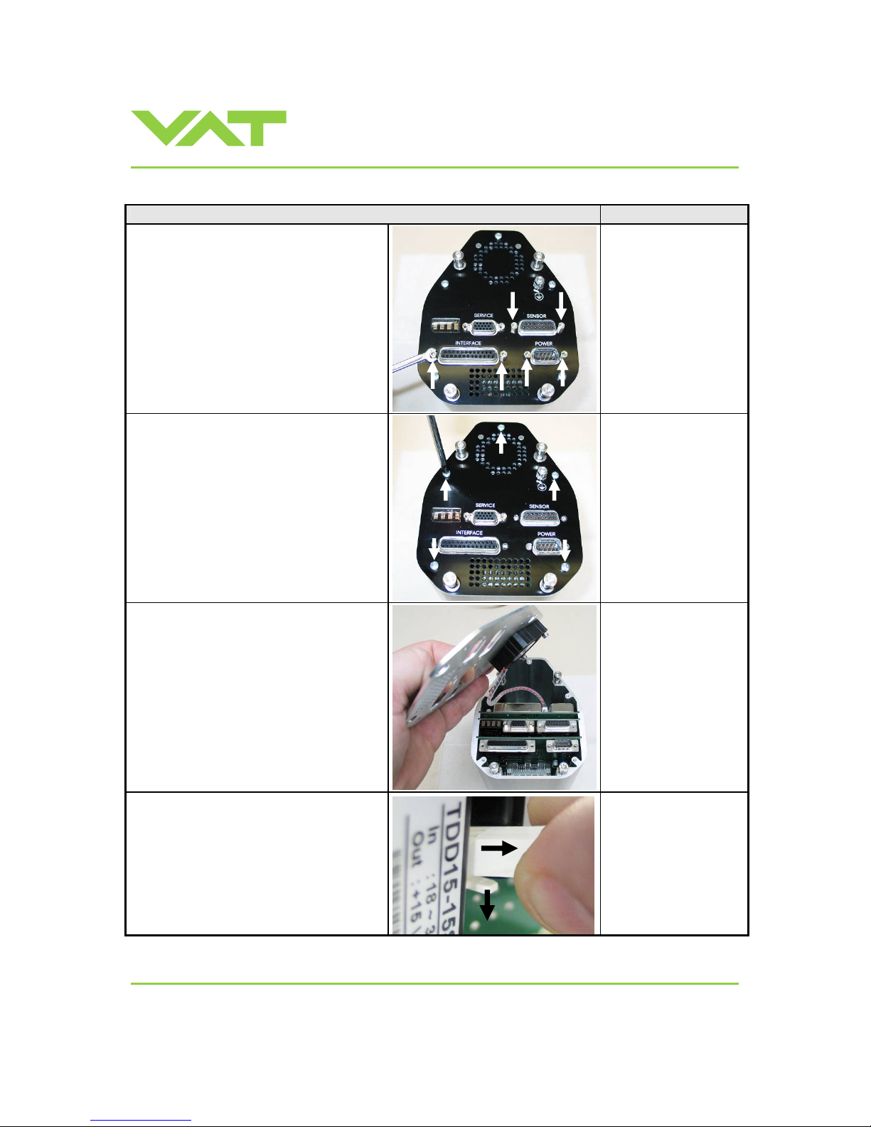
Installation, Oper ating & Maintenance Instructions
Series 651 DN 320-400 (I.D. 12“ - 16”), Logic
VAT Vakuumventile AG, CH-9469 Haag, Switzerland
Tel +41 81 771 61 61 Fax +41 81 771 48 30 [email protected] www.vatvalve.com
267736ED
2008-02-26
46/53
Description Required tool
1. Remove female screw locks from POWER,
SENSOR and INTERFACE connectors.
Open end wrench 4.5 mm
2. Remove the panel screws.
Pozidriv screw dri ver
size 1
3. Lift the panel carefully.
4. Push the connector release (1) a little down
and disconnect fan cable (2) from option
board.
2 1
Page 47
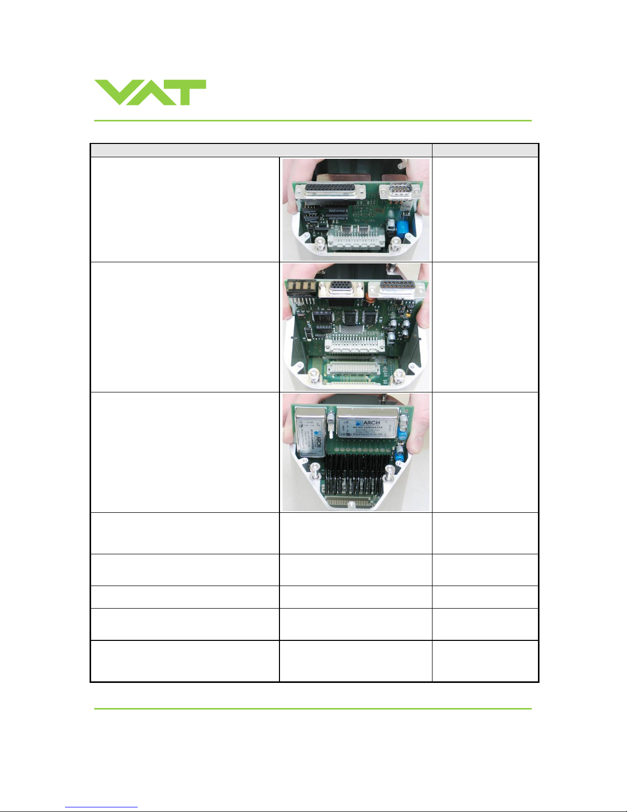
Installation, Oper ating & Maintenance Instructions
Series 651 DN 320-400 (I.D. 12“ - 16”), Logic
VAT Vakuumventile AG, CH-9469 Haag, Switzerland
Tel +41 81 771 61 61 Fax +41 81 771 48 30 [email protected] www.vatvalve.com
267736ED
2008-02-26
47/53
Description Required tool
5. Remove or replace interface board.
6. Remove or replace master board.
7. Remove or replace option board.
8. Insert master board and interface board
in reverse order as disassembled at
correct positions (seesteps 6 to 5).
9. Reconnect fan cable to option board (see
step 4).
10. Insert option board (see step 7).
11. Place the panel and tighten panel screws
with 1.1 Nm (see steps 3 to 2).
Pozidriv screw dri ver
size 1
12. Tighten female screw locks from
POWER, SENSOR and INTERFACE
connectors with 1.1 Nm (see step 1).
Open end wrench 4.5 mm
Page 48
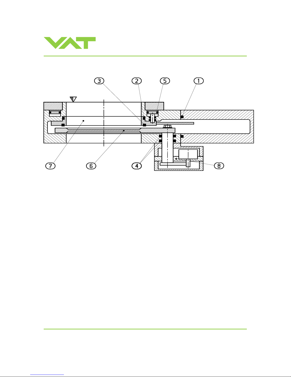
Installation, Oper ating & Maintenance Instructions
Series 651 DN 320-400 (I.D. 12“ - 16”), Logic
VAT Vakuumventile AG, CH-9469 Haag, Switzerland
Tel +41 81 771 61 61 Fax +41 81 771 48 30 [email protected] www.vatvalve.com
267736ED
2008-02-26
48/53
6 Drawing
Page 49
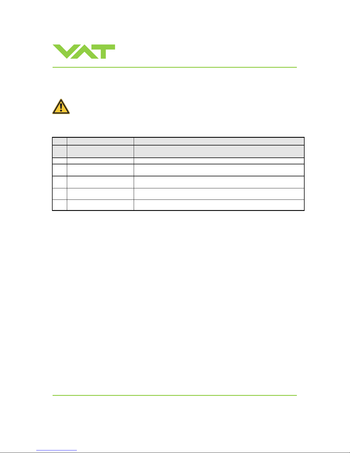
Installation, Oper ating & Maintenance Instructions
Series 651 DN 320-400 (I.D. 12“ - 16”), Logic
VAT Vakuumventile AG, CH-9469 Haag, Switzerland
Tel +41 81 771 61 61 Fax +41 81 771 48 30 [email protected] www.vatvalve.com
267736ED
2008-02-26
49/53
7 Spare parts
Please specify the fabrication number of the valve (see yellow label on valve) when ordering spare parts. This
is to ensure that the appropriate spare parts are supplied.
7.1 Control unit
Item Description
Valve size
Product ordering number
All sizes
651 . . - . . . .
Control unit Too many to list. Depends on configuration, please contact VAT.
Option board with SPS module
(±15VDC sensor power supply)
238091
Option board with PFO module
(power failure option)
242413
Option board
with SPS and PFO module
239390
Controller separation kit including
4.5m cable
264881
Page 50
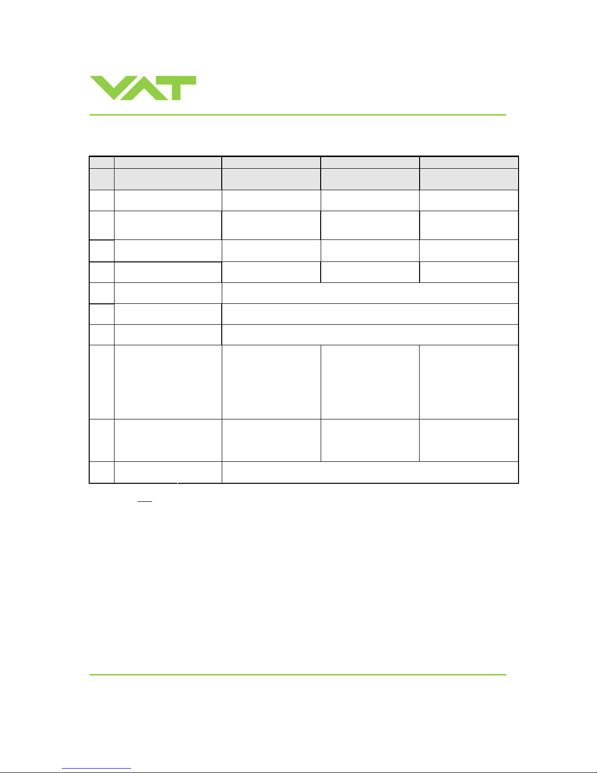
Installation, Oper ating & Maintenance Instructions
Series 651 DN 320-400 (I.D. 12“ - 16”), Logic
VAT Vakuumventile AG, CH-9469 Haag, Switzerland
Tel +41 81 771 61 61 Fax +41 81 771 48 30 [email protected] www.vatvalve.com
267736ED
2008-02-26
50/53
7.2 Valve unit
Item Description
Valve size
Valve part number
DN 320 / 12”
65150 - . . . .
DN 350 / 14”
65151 - . . . .
DN 400 / 16”
65152 - . . . .
Viton N-5100-280 N-5100-281 N-5100-282
1
Bonnet
seal
other materials on request on request on request
2
Body seal (Viton)
This includes a 2ml syringe of
vacuum grease
206529 230885 244435
Viton N-5100-279 N-5100-280 N-5100-282
3
Gate
seal
other materials on request on request on request
Seal kit vacuum (Viton).
This consists of item 2 and 3.
206528 230884 244437
2ml 206792
Syringe of vacuum
grease
5ml 206793
4 Actuator shaft seals (Viton)
N-5111-329
(2 pcs required per valve)
5 Sealing ring shaft seals (Viton)
N-7121-112
(24 pcs required per valve)
Pendulum plate:
- Blank B1 *) 251926 251933 251934
- Blank B2 *) on request on request on request
- Hardanodized B1 *) 249821 251918 251924
- Hardanodized B2 *) 249935 on request on request
- Nickel coated B1 *) on request on request on request
6
- Nickel coated B2 *) on request on request on request
Sealing ring
- Blank 230236 217677 239438
- Hardanodized 229310 222784 235224
7
- Nickel coated on request 211610 on request
B1 *) 322355
8 Actuator
B2 *) 346966
Note: Use only spare parts manufacture d by VAT to assure safe and reliable operation!
*) Refer to figures on next page to check for actuator position options.
Page 51
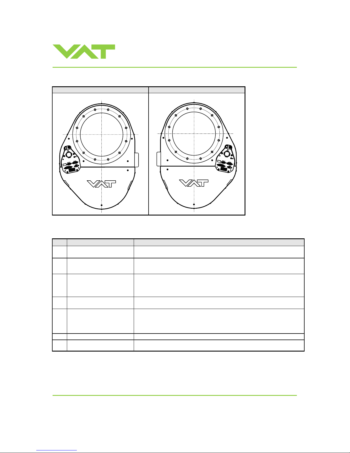
Installation, Oper ating & Maintenance Instructions
Series 651 DN 320-400 (I.D. 12“ - 16”), Logic
VAT Vakuumventile AG, CH-9469 Haag, Switzerland
Tel +41 81 771 61 61 Fax +41 81 771 48 30 [email protected] www.vatvalve.com
267736ED
2008-02-26
51/53
Actuator position options:
Valve with B1 actuator (standard) Valve with B2 actuator (option)
7.3 Accessories
Item Description Part number
24 VDC power supply unit
(input: 100 – 240 VAC)
249775
‘Control Per for m anc e Analyze r’
package for Windows
®
consisting
of software and cable
600SP-99NN-AAA
‘Control Vi ew’ soft ware for
Windows
®
248126
free download from www.vatvalve.com
or
available on order against charge
Servic e c able
(PC to valve connection)
230327
free wiring information available for download from www.vatvalve.com
Connector kit consisting of:
• DB-9 female POWER plug
• DB-15 male SENSOR plug
• DB-25 m ale INTE RFA CE plug
242411
Service Box 2 601BS-29NN-000
Control panel (rack-
mount version
of Service Box 2)
602BS-29NN-000
Page 52
Installation, Oper ating & Maintenance Instructions
Series 651 DN 320-400 (I.D. 12“ - 16”), Logic
VAT Vakuumventile AG, CH-9469 Haag, Switzerland
Tel +41 81 771 61 61 Fax +41 81 771 48 30 [email protected] www.vatvalve.com
267736ED
2008-02-26
52/53
7.3.1 Centering ring with Viton o-ring
Description
Valve size
Product ordering number
DN 320 / 12”
65150 - . . . .
DN 350 / 14”
65151 - . . . .
DN 400 / 16”
65152 - . . . .
Centering ring
with Viton o-ring
(for ISO-F installation
only)
Aluminum 32050-QAZV - 32052-QAZV
Page 53

Installation, Oper ating & Maintenance Instructions
Series 651 DN 320-400 (I.D. 12“ - 16”), Logic
VAT Vakuumventile AG, CH-9469 Haag, Switzerland
Tel +41 81 771 61 61 Fax +41 81 771 48 30 [email protected] www.vatvalve.com
267736ED
2008-02-26
53/53
8 Warranty
Each product sold by VAT Vakuumventi le AG (VAT) is warranted to be free from the manufacturing defects that adversely
affect the normal functioning thereof during the warranty period stated in VAT's «Terms of Sale» immediately following
delivery thereof by VAT, provided that the same is properly operated under conditions of normal use and that regular,
periodic maintenance and service is performed or replacements made, in accordance with the instructions provided by
VAT. The foregoing warranty shall not apply to any product or component that has been repaired or altered by anyone
other than an authorized VAT representative or that has been subject to improper installation or abuse, misuse,
negligence or accident. VAT shall not be liable for any damage, loss, or expense, whether consequential, special,
incidental, direct or otherwise, caused by, arising out of or connected with the manufacture, delivery (including any delay
in or failure to deliver), packaging, storage or use of any product sold or delivered by VAT shall fail to conform to the
foregoing warranty or t o the description thereof contained herein, the purchaser ther eof, as its exclusive remedy, shall
upon prompt notice to VAT of any such defect or failure and upon the ret urn of the product, part or component in question
to VAT at its factory, with transportation charges prepaid, and upon VAT's inspection confirming the existence of any
defect inconsistent with said w a rranty or any such failure, be entitled to have such defect or failure cured at VAT's factor y
and at no charge therefor, by replacement or repair of said product , as VAT may elect. VAT MAKES NO WARRANTY OR
REPRESENTATION OF ANY KIND, EXPRESS O R IMPLIED, (INCLUDING NO WARRANTY OR MERCHANTABILITY),
EXCEPT FOR THE FOREGOING WARRANTY AND THE WARRANTY THAT EACH PRODUCT SHALL CONFORM TO
THE DESCRIPTION THEREOF CONT AINED HEREIN, and no warrant y shall be implied by law.
Furthermore, the «Terms of sale» at the back of the price list are applicable.
 Loading...