

VASTEX E-100-2128, E-100-2331, E-100, E-1000, E-1-4731 Assembly And Operation Instructions Manual
...
Doc. # 01-04-021E
Year of Manufacture: 20____
Fluorescent Exposing Units
Original Instructions
E-100 & E-1000
Assembly and Operation Instructions
E100-2128
E1-4731
E100-2331
Vastex International, Inc.
1032 N. Irving St.
Allentown, Pa. 18109 USA
Phone# 610 434-6004 Fax# 610 434-6607
Contents Pg. #
Introduction, Machine Specifications 2
Safety Information 3
Assembly Instructions 4-5
Operating Instructions 6
Troubleshooting 7
Maintenance 8-9
Emulsion Tip 10-11
01-00-005/015 Warranty/Terms and Conditions 12
Electrical Drawing #: Revision:
Serial Number: VTX
(Please log your machine's serial number and date of purchase for future reference.)
Date: / /
Web Site www.vastex.com
Authorized Representative in Europe:
Certification Experts BV
Nieuwstad 100 1381 CE Weesp,
The Netherlands
Tel : + 31 (0) 294 – 48 33 55
Fax : + 31 (0) 294 – 41 46 87
Vastex E-mail assistance
Purchasing & Product Info:
sales@vastex.com
Electrical Support:
stech@vastex.com
Tech Support, Mechanical Setup, and Operation:
techsupport@vastex.com
Screen Printing Issues & Support:
printech@vastex.com

Doc. # 01-04-021E
Pg. 2
Introduction
Vastex Exposing Units
(Ultraviolet Exposure Systems)
Thank you for purchasing your printing equipment form Vastex International Inc.
Vastex has been designing and building printing equipment since 1960. We have knowledge and
experience, and are proud to supply the printing industry with quality equipment at an affordable price. You
can be confident your purchase will give you years of trouble free service.
Machine Specifications & Part Numbers
Overall Size (lid closed)
Depth x Width x Height
Weight
Screen Capacity
Power Requirements
Vacuum Pump
Vacuum Timer
Exposure Timer
Glass Reorder Numbers
Light Source
Vacuum Blanket
Lid Seal
E100-2128 E100-2331 E1-4731
32.75” x 37.75” x 14”
(83 x 88 x 36 cm)
151 lbs. (68.5kg) 174 lbs. (78.9kg) 273 lbs. (123.8kg)
21" x 28" 23” x 31” (2) 23" x 31" or a 31" x 47"
120v: 60Hz @ 3.5 Amps
240v: 50/60Hz @ 2 Amps
1/16 HP Diaphragm Pump
(120V P/N: 04-02-040)
(240V P/N: 04-02-041)
Analog P/N 04-01-085 Analog P/N 04-01-085 Analog P/N 04-01-085
Analog P/N 04-01-085 Analog P/N 04-01-085 Digital P/N: 04-01-083
P/N: 04-08-060 P/N: 04-08-048 P/N: 04-08-049
(4) 24" Black UV Bulbs
P/N: 04-08-006
P/N: EUB-2128 P/N: EUB-2331 P/N: EUB-4731
P/N: 04-08-039 P/N: 04-08-039 P/N: 04-08-039
36.5” x 41.75” x 14”
(93 x 106 x 36 cm)
120v: 60Hz @ 3.5 Amps
240v: 50/60Hz @ 2 Amps
1/16 HP Diaphragm Pump
(120V P/N: 04-02-040)
(240V P/N: 04-02-041)
(6) 28" Black HO UV Bulbs
P/N: 04-08-050
(106.7 x 132.1 x 114.3 cm)
240v: 50/60Hz @ 4 Amps
(120/240V—P/N: 04-02-060)
(12) 28" Black HO UV Bulbs
42” x 52” x 45”
120v: 60Hz @ 5 Amps
1/4 HP Rocking Piston
Pump
P/N: 04-08-050
Floor Model/Tabletop
Warranty
Table Top, optional stand
1 Year; Manufacturer
Essential Characteristics of tools which may be fitted to this machinery: This equipment is
not designed to be used with any additional attachments or tools, other than as specifically listed
available
defects
Table Top, optional stand
available
3 Years; Manufacturer
Defects
Floor model only
3 Years; Manufacturer
Defects

Doc. # 01-04-021E
Pg. 3
Safety
Intended Use:
This equipment is intended for the purpose of exposing screens and films with UV light in conjunction with
UV sensitive emulsions.
Safety:
The operator should read and understand this manual before operating this equipment. Store manual
and safety information near equipment for easy
access to operators.
Never leave equipment unattended while in operation.
Children and pets must be kept clear of the work area.
Do not store any objects on top of the exposing unit.
Unplug power cord before removing glass or entering control box.
Do not operate if any guard or cover has been removed.
Do not operate if power cord is damaged.
Safe Operating Temperature (Ambient): 55°F-100°F (13°C-38°C)
Do not attempt to defeat safety interlocks.
Noise and Vibration: This noise level produced by this equipment does not exceed 70 dB(A).
** WARNING HANDLE GLASS WITH CARE **
Wear gloves when handling the glass
Lay glass only on a flat protected surface
Tempered glass, although strong, can shatter if the edges are subject to an impact
General Information
Exposing Unit must be on a flat surface to
eliminate stress on the glass.
Caution! Screens must be free of sharp edges.
All surfaces coming in contact with vacuum
blanket should be rounded and smooth.
If installing onto the Vastex utility cart, see the
utility cart manual for
attachment procedure. (E-1000 Only)
Black UV light bulbs are used in Vastex exposing
units. Ultraviolet output of bulbs will lessen over
time. Replacing of bulbs is recommended if
longer exposure times are noticed. Changing
bulbs every 1 to 2 years is recommended. See
the Lamp Maintenance section of this manual for
details.
Keep the lid in the raised position when not in
use. It will increase the life of lifting cylinders
and the rubber blanket.
Tools Required
Philips Head Screw Driver
7/16”, 1/2”, 9/16" & 5/8” Wrenches
OR METRIC: 11mm, 13mm, 15mm, 16mm
Doc. # 01-04-021E
Pg. 4
Assembly
Getting started:
Your Exposing Unit has been fully assembled and tested in our factory. Both lid lifting
cylinders have been removed from their upper mounting stud and secured to the side of the
cabinet. Follow the steps in this manual to reattach them. Be careful not to damage the
rubber vacuum blanket when removing the Exposing Unit from it's crating.
It is best to keep the lid locked closed when lifting the exposing unit. Carefully remove the
unit from its crate and place it on a suitable surface. It is important that the surface be flat, an
uneven surface can put stress on the glass causing it to crack.
Placing the equipment into service and operating the equipment:
To place equipment into service, follow steps 1-4 (if applicable to your unit) and 5 on page 5.
To operate your exposure unit, follow the instructions on page 6 and the troubleshooting and maintenance
instructions on pages 7-9.
Stability during use, transportation, assembling, dismantling when out of service, testing, and
foresee able breakdowns:
This equipment is designed to be stable under all foreseeable conditions if the instructions provided
herein are followed. Do not place the units into positions not shown in this manual (e.g., on their sides) and
do not operate with any parts removed unless necessary for troubleshooting.
Safe transport, handling, storage: when the equipment is transported, it should moved by two or more
people. No other special precautions are required. Refer to page 2 for unit masses.
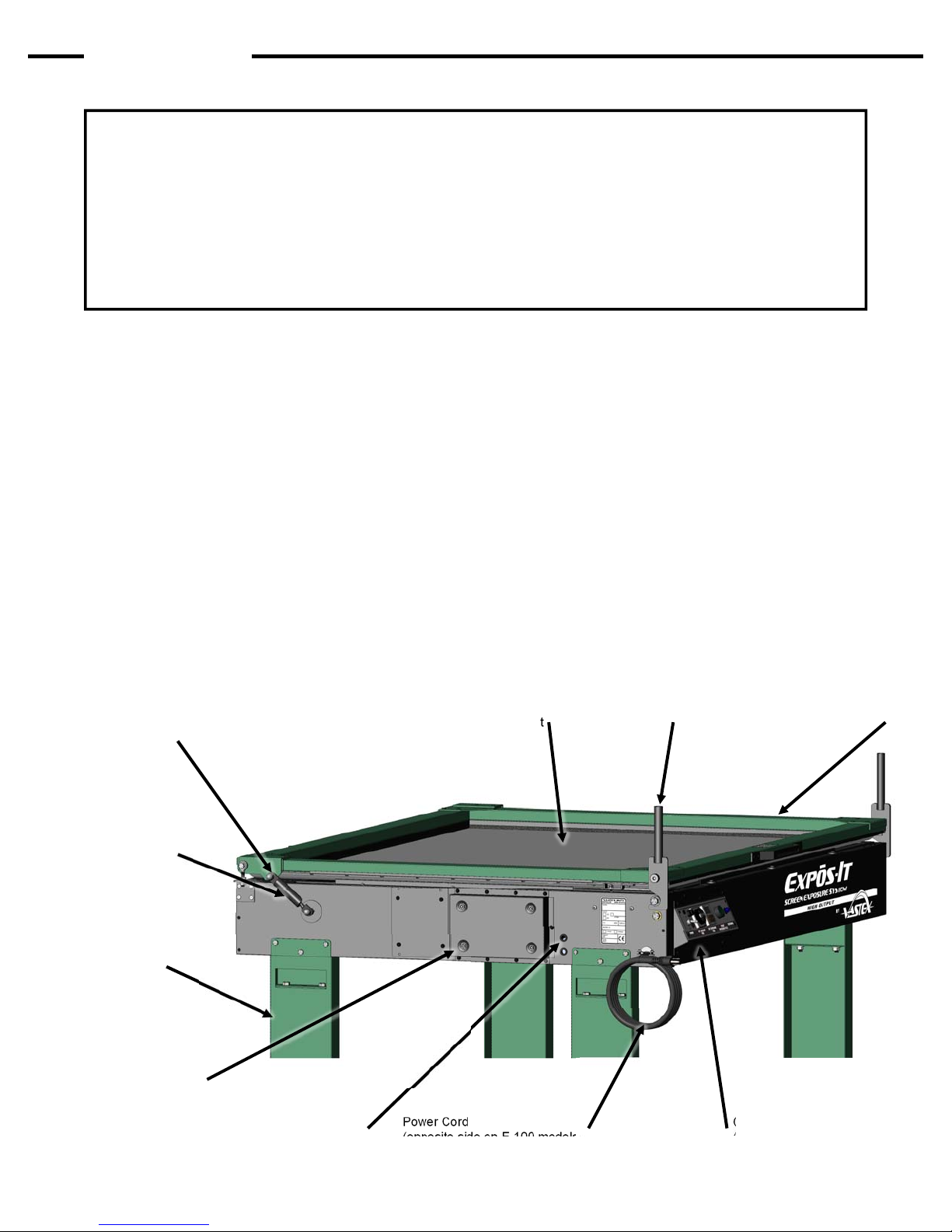
Acorn Nut & Upper
Cylinder Mounting Stud
(2) Lid Lifting Cylinders
(one on each side)
(2) Leg Assembly
(E1-4731 Only)
(2) Lid Locking HandleRubber Vacuum Blanket
Lid
Vacuum Pump Access Panel
(E1-4731Only)
Pump Exhaust
(opposite side on E-100 models)
Power Cord
(opposite side on E-100 models)
Control Panel
(opposite side on E-100 models)

Assembly Cont’d
Pg. 5
1) Install Legs on Exposing Unit
(Model E1-4731 only)
2) Place Legs on a clear spot on the floor,
28.5” (72.5cm) apart as shown in picture 1a.
Doc. # 01-04-021E
Steps 1 & 2
3) Lock lid handles as shown. Carefully lower
the exposing unit down onto the legs. Two
people are required to do this as caution
must be taken to not damage the machine’s
glass or rubber blanket.
4) Legs are installed with (8) 3/8" bolts, (16) 3/8”
washers and (8) 3/8” nuts. Use (2) 9/16”
open end wrenches and tighten all bolts well.
Step 3
Step 4
5) Install Lid Lifting Cylinders
Remove the acorn nut from the upper
cylinder mounting studs located on both
sides of the lid. Unlock and carefully lift lid far
enough to slide lifting cylinders onto studs.
Replace acorn nuts onto stud. Snug only with
a 5/8” wrench. Do not over tighten!
Step 5
Operation
Pg. 6
Overview:
Your Exposing Unit is equipped with Black UV bulbs, a vacuum and exposure
timer, vacuum pump, and start button.
The vacuum pump draws the air out from between the blanket and glass. This
flattens the coated screen and positive to the glass making for a sharper exposed
image.
Doc. # 01-04-021F
1) Raise the exposing unit lid and wipe the
glass surface clean with a lint free rag.
2) Position the screen with positive attached
onto the glass and against screen stops.
NOTE: Do not position any screen outside of the
indicated max screen area on the glass. Damage
to vacuum blanket can result.
3) Lay the small string attached to the rear of
the exposing unit over the edge of the
screen. This will assist in achieving a good
vacuum in the center of the screen.
4) Lower the lid and lock closed with both
handles.
5) Set the vacuum timer to about 1 minute for
a single screen. And on the E1-4731, 1.5 –2
minutes for two screens. A test should be
done to determine the best vacuum time for
your screen. It is best to have the blanket flat
several inches larger than the image area.
6) Set Exposure Time.
E-100 Exposing Units use an analog timer,
rotate knob to set time.
E1-4731 units use a digital timer, push buttons
to set time.
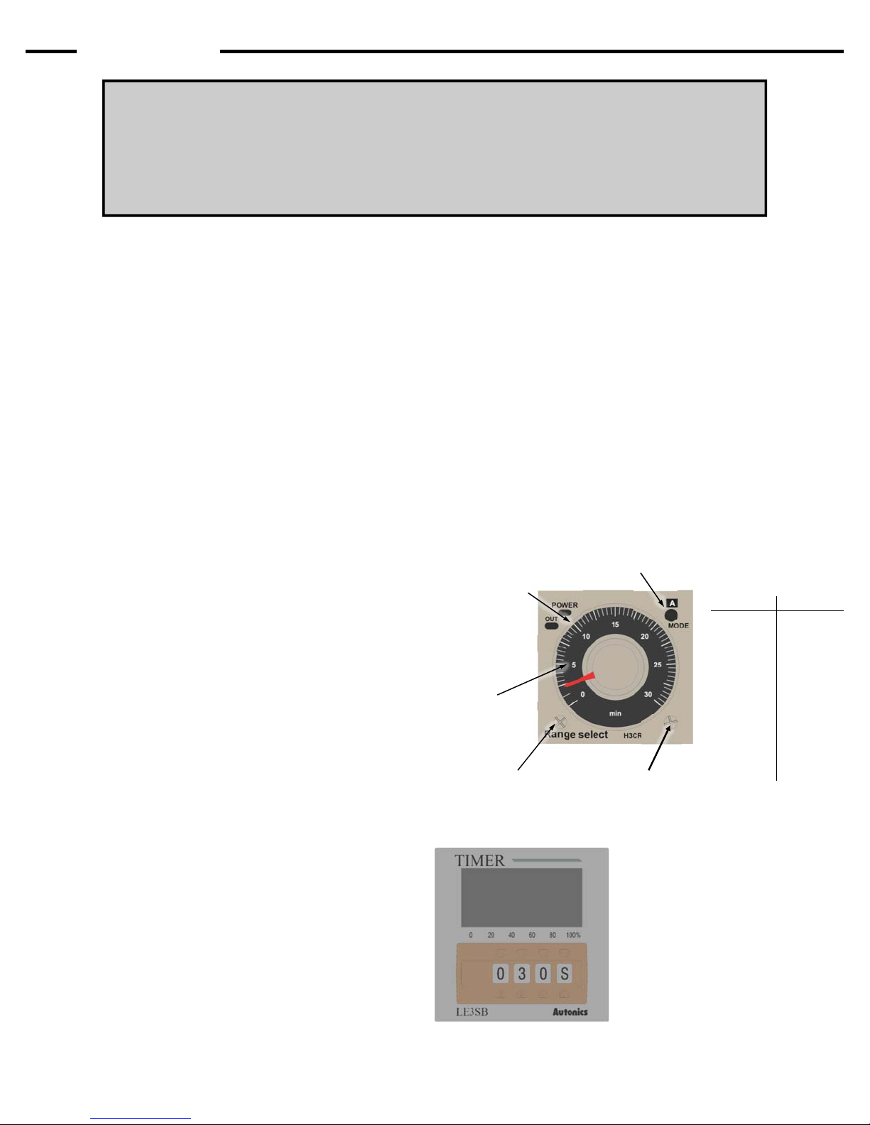
Analog Timers:
Timers are factory set to a 0-3 minute scale and 0-30
minute scale (E-100 models only) for vacuum and
exposure. The mode in the upper right corner is set
to A. Adjust the time by turning the dial to the
desired amount of time. The time scale can be
adjusted if desired.
Adjusting the Analog Timer Time Scales:
Adjust the range and time scale by turning the
RANGE SELECT and unit selection screw with a
Philips head screw driver.
Turning RIGHT increases the time scale
Turning LEFT decreases the time scale
MODE MUST BE SET TO A
Mode selection screw
Time adjustment dial
Time indicator
RANGE SELECT
adjustment screw
Unit selection
screw
Time Table (0-30 min)
Mark Time (s)
2.5 150
5 300
7.5 450
10 600
12.5 750
15 900
17.5 1050
20 1200
22.5 1350
25 1500
27.5 1650
30 1800
(Note: An exposure calculator is recommended to
determine correct exposure time)
7) Push the start button. The vacuum timer
will start while the pump draws the blanket
down. After the vacuum timer completes, the
expose timer and lights will start and run for
the preset time. After the time has expired,
the lights and vacuum pump will
automatically shut off. The screen is now
exposed.
8) Unlock the lid to break the vacuum and
remove the screen.
Digital Timer on Model E1-4731
Timer is set at the factory
to minutes. Adjust the
timer using the six buttons
on the left. The letter on
the right corresponds to
the units of time being
measured. An upper case
M means the timer can be
set between 0-999
minutes.

Troubleshooting
Pg. 7
Doc. # 01-04-021E
Loss of Vacuum:
This can be caused by several problems. Check the
following items in order listed.
1) Verify that vacuum pump is running.
2) Examine the rubber blanket for holes or cuts.
3) Check that the holes in the back screen stops
are not blocked. Turn on the pump and verify
that there is vacuum through the stops.
4) Check that the clear tube protruding through left
side of cabinet wall is unobstructed. This is the
vacuum pump exhaust.
5) Verify that the back glass seal is not damaged.
If needed, loosen the front glass retainer plate
and rotate the cams clockwise with a flat blade
screwdriver. and retighten the front retainer.
6) There is a foam seal around the perimeter of the
lid between the rubber blanket and lid frame.
With the lid locked down, check that the lid seal
and blanket is contacting the glass at all four
sides. If this seal is not contacting the glass it
will be necessary to adjust the lid lower.
Proceed as follows. (Pictures below for
reference)
Remove both Lid Lifting Cylinders from their
upper mounting stud. Carefully lower the lid.
Rear Lid Adjustment:
E-100: Using a 7/16 wrench, loosen (4) bolts at each
back corner. Push down on lid to slightly compress
seal and retighten bolts.
E1-4731: Using a 1/2" wrench, loosen the top nut
1/2 turn then tighten the bottom nut 1/2 turn. This will
adjust the lid down .025". Do this to both sides until
vacuum seal is achieved
Front Lid Adjustment:
All Exposits: Using a 9/16 wrench, loosen (2) bolts
at each front corner about 1/8 of a turn. Tap on the
top bolt head slightly to move the bearing down. Be
careful to avoid moving it too much. For reference,
measure from the top of the bearing to the bottom of
the lid when closed, do not adjust more than 1/16 of
an inch.
7) Contact Vastex for technical support if these
steps fail to resolve the problem.
Light Troubleshooting:
If a bulb fails to light, it will be necessary to remove
the glass to get to the bulbs (see next page).
Remove the faulty bulb and switch it to another
location on the light tray. If the bulb still does not
light the bulb must be replaced. If the bulb does light
there is a wiring problem. Contact Vastex for
technical support.
Lid Adjustment Bolts Rear Lid Adjustment Nuts Loosen 1/8 turn for adjustment
Rear Lid Adjustment
(E-100 models)
Rear Lid Adjustment
(E1-4731)
Front Lid Adjustment
(All models)
Maintenance
Pg. 8
Doc. # 01-04-021E
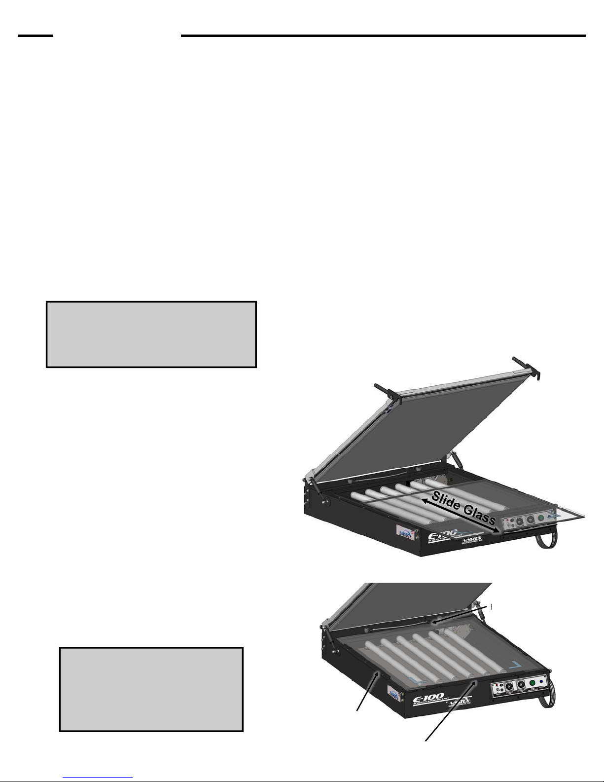
Glass Removal / Installation
There are three glass retainers. One on each
side to square the glass to the rear seal and one
in the front with special cams. The cams are used
to gently push the glass back against the rear
seal.
1) Remove the cams and front retainer. Slide
the glass towards the front to remove.
Carefully set glass on a flat, protected
surface. The cams are used to gently push
the glass back against the rear seal.
2) It is important to keep the inside of the
cabinet clean. It is a good idea to vacuum out
any loose debris from inside the cabinet.
Refer to the replacing a light bar if needed.
Wear gloves when handling the
glass. Glass is tempered and
although strong, can shatter if the
edges are subjected to an impact.
4) Reinstalling the glass.
Before installing the glass, switch the
vacuum pump on and off to verify it is
functioning properly. Clean both sides of the
glass with glass cleaner and a lint free rag.
Vacuum inside of cabinet. Position the glass
seal side down, blue tape towards the front,
on the front edge of the cabinet, and between
the side retainers. Slide glass back until it
contacts and it seated squarely against the
back seal. Place the front glass retainer and
the three cams against the glass front. Install
the screws but only snug the screws. Using a
1/4” flat screw driver in the cam slots, rotate
each cam to push the glass back. Do not
over tighten the cams but apply enough
pressure to make a seal. Now tighten the
center screws. If the vacuum leaks, go back
and tighten the cams a bit more.
3) Bulb Installation/Removal
Be sure your hands are clean or clean
gloves are used. Install a bulb by inserting
the pins on the end of the bulb into their
holders mounted on the light tray. Rotate
bulbs 90 degrees until it clicks in place. Test
the bulbs before installing the glass.
a) Plug in the power cord.
b) Turn the exposing unit on.
c) Set the vacuum timer to “0”.
d) Press the START button.
All lights should now be on. If any light is not
working, check that the pins are not bent and
are correctly seated into the bulb holders.
Removal of bulbs is the reverse of
installation.
Note: The glass must be tight
against the back glass seal in
order to make a good vacuum.
Special cams help to apply
pressure. Do not over tighten.
Rear glass seal
Side glass retainer
(1 each side)
Front glass retainer, with 3 cams.

Maintenance Cont’d
Pg. 9
5) Screen Stops
E-100: Two Rear screen stops are installed at
the factory.
E1-4731: Rear stops are installed at the factory.
Doc. # 01-04-021E
Rear screen stops
E100-2128
E100-2331
E1-4731

Emulsion information
Pg. 10
for the screen printer
A technical information article
by Douglas Grigar
Screen printers have available six types
of photoreactive stencil materials. There
are three direct emulsion choices,
diazo, diazo/photopolymer (dual cure),
and SBQ-photopolymer. There are also
three photo reactive film choices,
indirect film, direct/indirect film, and
photoreactive capillary films.
Diazo emulsions are the least
expensive and the first of the three
emulsion types available on the market.
Diazo emulsions are mid range in
available exposure latitude and can
have good edge definition. Drawbacks
are that many require hardeners for
long runs or water resistance lower
solids content is often needed for
reasonable viscosity.
Diazo Photopolymer emulsions are
hybrids of the diazo and photopolymers
and are also called dual cure. Dual cure
emulsions are the newest available
emulsions. Due to the hybrid nature
they have the largest available feature
and quality range. Dual cure emulsions
will have the largest exposure latitude
and are available in various levels of
water and solvent resistant features.
Dual cure emulsions generally have the
best resolution, definition, and bridging
qualities. Dual cure emulsions are
midrange in price, and higher solids
content versions are available with
reasonable viscosity.
SBQ- Photopolymer emulsions are
very fast in their exposure speeds but
also have the smallest exposure
latitude. They are pre mixed and have
the longest shelf life. Pure
photopolymer emulsions are the most
expensive and are best matched with
high quality single point exposure
systems. Pure photopolymer emulsions
have good resolution, definition, and
bridging qualities. Pure photopolymer
emulsions have the highest solids
content available with reasonable and
often excellent viscosity.
The solids content in an emulsion does
example would be that pure
photopolymer emulsions are available
in very high solids content with low
viscosity. Emulsion viscosity can also
change with temperature. Lower
temperatures cause the emulsions to
thicken. Solids content less than 30%
with low viscosity are often difficult to
coat without a mess. In addition, lower
solids percentage will require multiple
coatings to achieve reasonable mesh
coverage.
Fig. 1
Emulsion Over Mesh or EOM is a
measurement of the emulsion thickness
on the face or substrate side of the
mesh. EOM is a percentage of the
mesh thickness. (Fig. 1) Too low of an
EOM ratio will prevent a good gasket
seal, prevent good detail resolution,
and increase chances of saw tooth
edges. Manufacturers recommend an
EOM ratio of 10 to 20 percent.
With an emulsion stencil, more is not
better. Too much emulsion on the face
of the screen can cause difficult ink
transfer and details can break down in
a run. Emulsion drip from the mesh
while drying is a definite indication that
the coated emulsion is too thick.
Your emulsion manufacturer can
recommend a coating procedure for
each mesh count using a rounded or
sharp coating edge.
Fig. 2
The step coating procedure (Fig. 2) is
used to coat a screen to find your best
coating technique for that mesh count.
The step coating procedure starts with
a stroke on the face of the mesh. Then
coat the squeegee side once over the
entire screen. Coat again the squeegee
side on only two thirds of the screen,
then coat again one third of the
squeegee side (all wet on wet).
Dry your screen as normal. When dry,
face coat with the sharp edge of the
squeegee two thirds of the screen from
a crossing direction (perpendicular)
then dry face up. When the screen is
dry apply the last coat of emulsion on
the face side covering only one third of
the same direction as the last face coat,
then dry. With the face coatings there
will be nine examples of coating
thicknesses. Pick an exposure time that
fits the median coating technique and
expose the screen with a test positive
that covers all of the coating changes.
Wash out and dry as normal. Now you
can view the emulsion with a loop or
microscope. Inspect the changes in
thickness, then print with this screen
and inspect the printed results. With the
printed results compared to the visual
inspection, the best coating technique
for that mesh count can be determined.
Standardized mesh thread thickness
and weave for each mesh count is
needed for consistent and reliable
results.
The step coating procedure can be
used while eliminating some of the
steps, or replace the face coatings with
all wet on wet coating strokes.
All manufacturers recommend drying
coated screens with the face down
(squeegee side up) in a horizontal
position. A slightly elevated temperature
(not over 110 deg. F.), in a filtered
drying room or cabinet, will dry screens
in record time, often less than half an
hour. A dehumidifier will drop emulsion
drying time further.
Fig 3
Once the screen is dry, direct emulsion
will dry and conform to the profile of the
mesh fabric causing small hills and dips
in the surface. The smoothness of the
dry emulsion can be measured and is
represented by the term Rz value. (Fig.
3) The lower the Rz measurement
number the smoother the surface.

Fig. 4
Pg. 11
Surface smoothness can affect your
substrate to stencil gasket. The lower
Rz numbers will be produced only by
machine coating or film products.
Direct/indirect and capillary films will
produce the lowest Rz numbers
possible for screen stencils. High solids
content emulsions and face coating
(second or more coats of emulsion over
dry first coatings) can also lower your
Rz measurements. (Fig. 4) Exact EOM
and Rz numbers can only be measured
by special testing equipment.
Indirect film products are
presensitized emulsions on film. They
are produced to expose and develop
before they are attached to the screen
mesh. Indirect film has fallen out of
general use as products that are easier
to use and have superior reproduction
properties are now available.
(emulsion up) on a hard flat surface.
(Fig. 7)
Fig. 7
Place a screen (squeegee side up)
onto the film, lightly mist the mesh with
a spray gun until the screen starts to
draw up the capillary film into the fabric.
(Fig. 8)
pressure stroke with a soft squeegee.
(Fig. 9) The use of newsprint on your
work surface will help with clean up.
Fig. 9
Stay consistent and you will be able to
predict your results with greater
accuracy. Your goal should be
consistency, predictability, and
repeatability.
Graphics and text copyright 2002
Douglas Grigar dgrigar@hotmail.com
Fig. 5
Capillary films are a photosensitive
emulsion layered onto a film backing.
(Fig. 5) The name is indicative of the
action that causes the adhesion,
capillary action. With wet screen fabric
the film will draw into the mesh when
placed in contact with the face of the
screen.
Capillary films suffer from past bad
reputation for delamination (Fig. 6) the
current products available are capable
of long runs and excellent detail.
Capillary films produce the lowest Rz
numbers possible and can save large
amounts of screen room production
time.
Fig. 6
Capillary films are best applied with the
Fig. 8
Direct/indirect film products
(combination stencils) are two-part film
and emulsion combinations. Films
assure low Rz numbers and high detail
print quality. Direct emulsions produce
high stencil durability. Direct/indirect film
systems combine the best features of
direct emulsion and film products,
creating a strong, high definition stencil
that will make longer runs possible with
direct emulsion.
Direct/indirect film products require a
coating of direct emulsion. Then the film
can be adhered to the face (substrate
side) of the screen. One method is to
coat the screen (one stroke on each
side of the screen) then place the
screen (squeegee side up) on the film
(emulsion side up) and stroke the
squeegee side of the screen with a low

Vastex Warranty
Pg. 12
(1.) Vastex, hereinafter referred to as “seller” warrants only to its original “purchaser”, who holds a copy of the original invoice and is the original end user of the equipment in question, its
new equipment against manufacturer defects in materials or workmanship on a pro-rated basis. Warranty period begins from date of shipment to the buyer and will only apply to customers
paid in full. Warranty periods are as follows: one (1) year for E-1000, three (3) years for all other complete machines (including F-Flash), fifteen (15) years for infrared heaters (excluding FFlash) installed by Vastex in a new dryer, three (3) years for replacement infrared heaters, and one (1) year for replacement parts. Rubber blankets, light bulbs and glass on exposure units
are particularly subject to wear while in use. Wear is not covered by this warranty but as stated above only manufacturers defects are covered. All sales made through Vastex dealers must
be certified by that dealer before a warranty replacement is issued. All equipment is thoroughly tested and inspected before packaging. This warranty does not cover minor cosmetic
damages that occur during shipment that do not affect the functionality of the equipment.
(2.) This warranty is expressly contingent upon the buyer delivering to seller, at the address below, with all transportation charges prepaid, the part or parts claimed to be
defective within the above mentioned warranty periods stated in paragraph one. The defective part or parts will be repaired or replaced at the discretion of Vastex International,
Inc. If the equipment in question is less than one (1) year old, it will be shipped to the customer at no charge, with an RGA issued by Vastex for the defective part. The defective
part must be shipped back to Vastex freight prepaid within 30 days or the account will be billed. If the equipment is more than a year old, the part will be shipped after we
receive the defective part. If it’s necessary to expedite the movement of parts and to minimize down time to the buyer, the replacement part shall be supplied on a C.O.D. basis. If
testing and analysis of said part by the seller or its supplier discloses that said part is defective, the cost of said part will be refunded to the buyer on a prorated basis.
(3.) Except as otherwise provided herein, the equipment is being sold “as-is”. Final determination of the suitability of the equipment for the use contemplated by the buyer, is the sole
responsibility of buyer, and seller shall have no responsibility in connection with the suitability.
(4.) All warranties implied by law, including the implied warranties of merchantability and fitness are hereby limited to manufacturer defects in materials or workmanship during the
warranty period stated in paragraph one. The express warranty and remedies contained herein and such implied limited warranties are made solely to the sole warranties and remedies and
are in lieu of all other warranties, guarantees, agreements, and other liabilities, whether express or implied, and all other remedies for breach of warranty or any other liability of seller, in no
event shall seller be liable for consequential damages.
No person, agent, distributor, or service representative is authorized to change, modify or extend the terms hereof in any manner whatsoever.
These terms and conditions are an essential part of the transaction between the parties and constitute the entire agreement between them with respect to the same.
Some states do not allow limitation on how long an implied warranty lasts of the exclusion or limitation of incidental, or consequential damages, so the above limitation may not
apply to you.
This warranty gives you specific legal rights, and you may also have other rights which vary from state to state.
Infrared heaters are the only replacement parts covered for a period of (3) years from date of shipment and contingent to receipt of payment in full.
Electrical components cannot be returned once installed unless proven defective.
Please refer to doc. 01-00-015 for specific terms and conditions of sale and the limited warranty.
Please refer to doc. 01-00-017 for V-2000HD printer warranty.
Updates: V1000 to 3 year warranty 01/09/12, Heater warranty to 15 years 01/02/2012.
---------------------------------------------------------------------------------------------------------------------------------------------------------------------------------------------------------------------
TERMS AND CONDITIONS OF SALE AND LIMITED WARRANTY Doc.#01-00-015
1. Buyer’s order will constitute an offer in accordance with the terms hereof and such offer, upon acknowledgment of Seller, will constitute the agreement between Buyer and Seller.
Buyer’s order after such acknowledgment by Seller will not be subject to cancellation, change or reduction in amount, or suspension by Buyer of deliveries, unless prior to such
action Buyer has obtained Seller’s written consent. Notwithstanding anything to the contrary in Buyer’s Purchase Order or other communications, the parties agree to be bound by
these Terms and Conditions. Acceptance of the product by the Buyer shall be deemed to constitute unconditional acceptance of these Terms and Conditions.
2. Any of these terms, conditions and provisions of Buyer’s order which are inconsistent with Seller’s acknowledgment and these Terms and Conditions of Sale shall not be binding on
the Seller and shall be considered not applicable to any sale so made. No waiver, alteration or modification of any of the provisions on either side of the document shall be binding
upon Seller unless agreed to in writing by Seller.
3. (a) All prices are F.O.B. Seller’s Plant and method of delivery and routing shall be at Seller’s discretion, unless specifically otherwise stated herein. Notwithstanding any agreement
4. It is understood that deliveries will be made in accordance with Seller’s regular production schedule. Every reasonable effort will be made to meet the Buyer’s required delivery
5. Seller reserves the right to increase the prices prior to Seller’s acceptance of order and/or after expiration of any price quoted by Seller.
6. Unless otherwise stated in writing, Seller’s prices do not include sales, excise, value-added or other taxes. Consequently, in addition to the price specified herein, the amount of any
7. Seller reserves the right, at any time, to revoke any credit extended to Buyer because of Buyer’s failure to pay for any products when due or for any other reason deemed good and
8. (a) SELLER’S LIABILITY SHALL BE LIMITED TO SELLER’S STATED SELLING PRICE PER UNIT OF ANY DEFECTIVE GOODS AND SHALL IN NO EVENT
9. The remedies herein reserved by Seller shall be cumulative and in addition to any other legal remedies. No waiver of a breach of any portion of this contract shall constitute a waiver
10. These Terms and Conditions constitute the entire agreement of the parties. No amendments, changes, revisions or discharges hereof in whole or in part shall have any force or effect
11. This contract shall be governed and shall be construed according to the domestic laws of the Commonwealth of Pennsylvania.
12. Anything herein to the contrary notwithstanding, any action for alleged breach by Seller of the contract between the parties, including but not limited to any action for breach of the
13. This agreement shall inure to the benefit of and be binding upon the parties hereto, their respective successors and permitted assigns.
14. All notices required by this contract to be given by either party shall be sent in writing or by facsimile and shall be addressed to the last known address of such other
-------------------------------------------------------------------------------------------------------------------------------------------------------------------------------------------------------------------
to pay freight, delivery of products purchased hereunder to a common carrier or licensed trucker shall constitute delivery to Buyer and be determinative of the date and time of
shipment and all risk of loss or damage in transit shall be borne by Buyer. If the Buyer fails to accept the goods from the common carrier or licensed trucker, the Seller shall be
entitled to claim payment from the Buyer. Seller shall arrange for storage, the risk and the cost, including insurance costs, to be borne by the Buyer (and Buyer agrees to pay
such amounts upon demand) except if the failure to accept delivery is due to any of the exceptions noted in Paragraph 4.
(b) Terms of payment shall be as stated on invoice.
dates but Seller will not be liable for damages or be deemed to be in default by reason of any failure to deliver or delay in delivery due to any preference, priority, allocation or
allotment order issued by the Government, whether Federal, State or local, or causes beyond its control including but not limited to, Acts of God or a public enemy, acts of
Government, fires, floods, epidemics, quarantine restrictions, strikes, lockouts, freight embargoes, severe weather, unavailability of materials or shipping space, delays of carriers or
suppliers or delays of any subcontractors. Should delay in delivery be caused by any of the circumstances mentioned in this paragraph, such extension of the delivery period shall be
granted as is reasonable under the circumstanced of the case. Should delay be caused by an event not specifically mentioned in this paragraph, damages will be limited to
cancellation of the purchase order without penalty, and refund of any monies deposited or prepaid on the purchase order with no liability for any consequential or incidental damages.
present or future sales, use, excise, value-added or other tax applicable to the manufacture, sale, purchase or use of the products hereunder shall be paid by Buyer, or in lieu thereof,
Buyer shall provide Seller with a valid tax exemption certificate acceptable to the taxing authorities.
sufficient by Seller and in such event, all subsequent shipments shall be paid for prior to at delivery at Seller’s option.
INCLUDE BUYER’S MANUFACTURING COSTS, LOST PROFITS, GOODWILL, OR ANY OTHER SPECIAL, INDIRECT, INCIDENTAL OR CONSEQUENTIAL
DAMAGES, ARISING OUT OF THE AGREEMENT, THIS CONTRACT, THE SALE OF THE PRODUCTS TO THE BUYER OR THE USE OR THE PERFORMANCE
OF THE PRODUCTS. Seller may at its discretion repair, replace or give the Buyer credit (pro-rated) for such defective products.
(b) Notwithstanding anything herein to the contrary, Seller shall have no liability for alleged defects with the products which are not specified in written notice from the Buyer to the
Seller within thirty-six (36) months from the date of shipment of machines. Seller shall pass to Buyer any warranty received by Seller from the manufacturer of Limited Life
Components, which in most cases is 12 to 18 months.
(c) Seller shall have no liability under this Limited Warranty unless Buyer has paid in full for the products. Further, this Limited Warranty is expressly contingent on Buyer’s
delivery to Seller, all costs prepaid, the defective part(s) within thirty-six (36) months of shipment to Buyer, together with a written statement specifying the alleged defect(s).
Any replacement part(s) shall be shipped to Buyer on a C.O.D. basis.
(d) SELLER SPECIFICALLY EXCLUDES ALL WARRANTIES, EXPRESSED, IMPLIED OR OTHERWISE, EXCEPT AS STATED EXPLICITLY IN THESE TERMS AND
CONDITIONS OF SALE. SELLER DISCLAIMS THE WARRANTY OF MERCHANTABILITY AND FITNESS FOR A PARTICULAR PURPOSE.
of continuing or future breach of such provision or of any other provisions hereof.
unless set forth in writing and signed by the parties hereto. This contract shall not be assignable by Buyer voluntarily by operation of law or otherwise without Seller’s written
consent.
warranties herein set forth, shall be barred unless commenced by Buyer within one (1) year from the date such cause of action accrued.
party. Notices shall be deemed to have been received on the fifth business day following deposit in the mail.
VASTEX 1032 N.
Doc#01-00-005C Revised 10/15/2015
IRVING ST.
INTERNATIONAL ALLENTOWN PA. 18109 USA
 Loading...