

Page 1
GEBRUIKERS HANDLEIDING
NIVA VENTILO-CONVECTOR
MANUEL D’UTILISATION
NIVA VENTILO CONVECTEUR
GEBRAUCHSANWEISUNG
NIVA GEBLÄSEKONVEKTOR
USER MANUAL
NIVA FAN COIL UNIT
MANUALE D’USO
NIVA VENTIL CONVETTORE
INSTRUKCJA INSTALACJI,
I UŻYTKOWANIA
NIVA KLIMAKONWEKTOR
FC75 / FC95 / FC115
NIVA FC
Page 2
Deze unit voldoet aan de Europese richtlijnen:
• Laagspanningsrichtlijn 2014/35/EU
• Elektromagnetische compatibiliteit 2014/30/EU
De pictogrammen in het volgende hoofdstuk voorzien de noodzakelijke
informatie voor correct en veilig gebruik van de machine op een snelle en
ondubbelzinnige manier.
VEILIGHEIDSPICTOGRAMMEN
Algemeen gevaar
Informeert het betrokken personeel dat de beschreven handeling, indien niet
uitgevoerd volgens de veiligheidsvoorschriften, het risico van lichamelijk letsel
met zich meebrengt.
Gevaar voor hoge elektrische spanning
Informeert het betrokken personeel dat de beschreven handeling, indien niet
uitgevoerd volgens de veiligheidsvoorschriften, het risico van elektrocutie met
zich meebrengt.
Gevaar vanwege hoge temperaturen
Informeert het betrokken personeel dat de beschreven handeling, indien niet
uitgevoerd volgens de veiligheidsvoorschriften, het risico van brandwonden met
zich meebrengt.
Verbod
Verwijst naar verboden handelingen.
CONFORMITEIT
SYMBOLEN
Page 3
NL
FR
DE
EN
IT
PL
CONTENTS
1. ALGEMEEN
Elektronisch paneel 2
Display 2
Toetsfunctie 3
Hoofdschakelaar 3
Activering 3
Verwarm-/koelmodi instellen 4
Stand-by 4
Temperatuurselectie 4
Automatische werking 5
Stille werking 5
Nachtelijke werking 5
Werking bij maximale ventilatiesnelheid 5
Toetsenvergrendeling 6
Helderheid tot het minimum beperken 6
Deactivering 6
Oset van de regeling van de kamertemperatuursonde 6
Uitschakelen gedurende lange periodes 7
Foutsignalen 7
2. ONDERHOUD
Externe reiniging
Reiniging van het luchtaanzuigingsfilter
Reiniging van de filters
Suggesties om stroom te besparen
3. PROBLEMEN OPLOSSEN
Problemen oplossen 10
Tabel om problemen op te lossen 11
4. GARANTIEVOORWAARDEN
Garantievoorwaarden 12
CONFORMITEIT / SYMBOLEN / PICTOGRAMMEN 01
Page 4
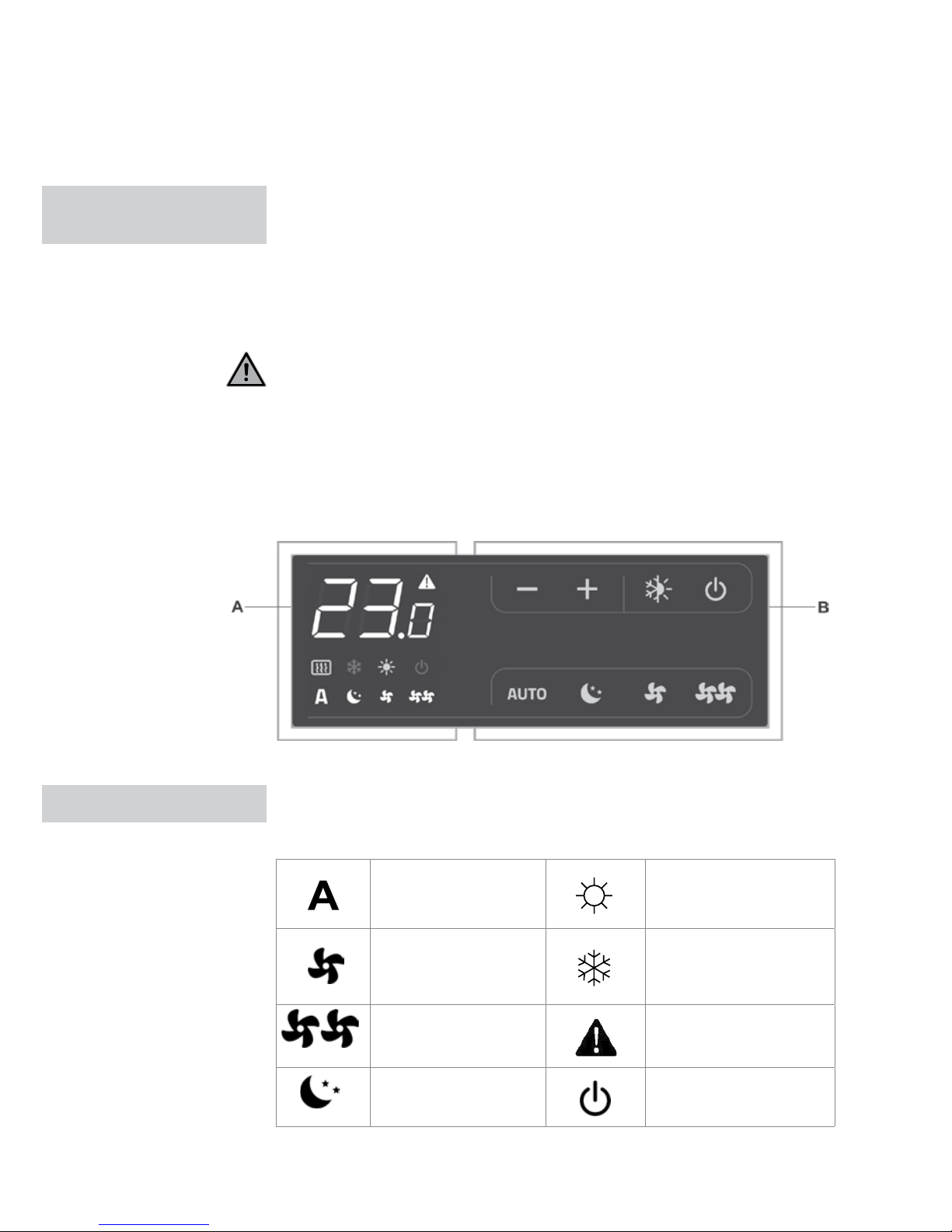
Deze regelaar zorgt ervoor dat de kamertemperatuur (met offset instelbaar
van op het toetsenbord) volledig autonoom wordt aangepast via de AUTO-,
SILENT- NIGHT- en MAX-programma’s aan de hand van een sonde die zich
aan de onderkant van het apparaat bevindt en die voor vorstbescherming in
stand-bymodus zorgt.
Het controlepaneel heeft een geheugen zodat instellingen niet verloren gaan
als het apparaat uitgeschakeld wordt of als de stroom uitvalt.
20 seconden na de laatste handeling wordt de helderheid van het paneel
verlaagd voor meer nachtelijk comfort. De kamertemperatuur verschijnt op het
display. Druk op een willekeurige toets om terug te gaan naar de maximale
helderheid. De 10 kΩ watertemperatuursonde die zich in de batterij van het
apparaat bevindt, reguleert het minimumniveau bij verwarming (28°C) en het
maximumniveau bij koeling (20°C).
Ook alle statussen en alarmsignalen worden met 8 specifieke symbolen
weergegeven op het display
Automatische werking Verwarming aan
Stille werking Koeling aan
Maximale
ventilatiesnelheid
Alarmindicator
(continu licht)
Nachtelijke werking Paneel uit-indicator
1 ALGEMEEN
ELEKTRONISCH
PANEEL
DISPLAY
02 ELEKTRONISCH PANEEL / DISPLAY
A Display
B Toetsen
Page 5
NL
FR
DE
EN
IT
PL
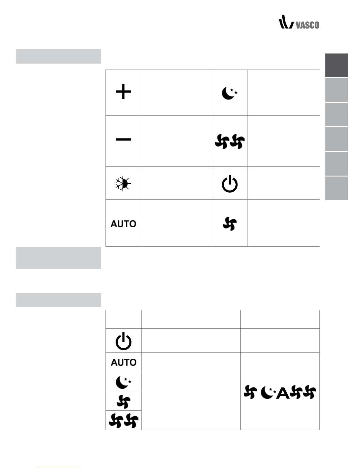
De verschillende functies worden ingesteld aan de hand van
8 toetsen met achtergrondverlichting:
Temp +
dient om de ingestelde
temperatuur te
verhogen
Nachtwerking: beperkt
de ventilatiesnelheid
naar een bepaald niveau
en de temperatuur wordt
automatisch aangepast.
Temp dient om de ingestelde
temperatuur te verlagen
Werking tegen
maximale snelheid:
maakt het mogelijk
om de maximale
ventilatiesnelheid in te
stellen
Verwarmen / Koelen:
om de werkingsmodus
te veranderen naar
verwarmen of koelen
AAN/Stand-by: dient om
het apparaat te activeren
of om het in standbymodus te zetten.
Stelt de regulatieventilatiesnelheid tussen een min.en max.-waarde in naar
een volledig automatische
modus
Stil: beperkt de
ventilatiesnelheid naar
een meer begrensde
waarde
Om het apparaat te bedienen via het controlepaneel moet het aangesloten zijn
op het stroomnet.
Als er een hoofdschakelaar is geïnstalleerd op de voedingskabel, moet deze
ingeschakeld zijn.
- Schakel het apparaat in door de algemene schakelaar aan te zetten:
Het apparaat activeren
Toets Werking Display
Druk op de AAN Stand-bytoets Van uit naar aan
Selecteer een van de vier
werkingsmodi door op de
overeenkomstige toets te drukken.
TOETSFUNCTIE
ALGEMENE
OPSTARTPROCEDURE
ACTIVERING
TOETSFUNCTIE / ALGEMENE OPSTARTPROCEDURE / ACTIVERING 03
Page 6
VERWARM-/
KOELMODUS
INSTELLEN
STAND BY
AUTOMATISCHE
STILLE WERKING
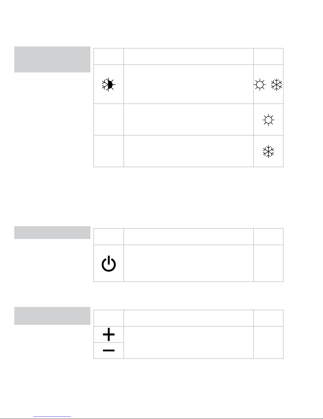
Toets Werking Display
Houd de Verwarmen/Koelen-toets ongeveer 2
seconden lang ingedrukt om de werkingsmodus
te veranderen naar verwarmen of koelen. De
modus wordt aangegeven door de 2 symbolen die
verschijnen als verwarmen of koelen actief is.
Tijdens het verwarmingsproces geeft het symbool
weer wanneer het instelpunt hoger is dan de
omgevingstemperatuur, beide zijn uitgeschakeld als
het instelpunt lager is.
Tijdens het koelproces geeft het symbool weer
wanneer het instelpunt lager is dan de omgevingstemperatuur, beide zijn uitgeschakeld als het
instelpunt hoger is.
Als een van de twee symbolen knippert, betekent dit dat de watertemperatuur
(warm of koud) niet voldoende is. De ventilator wordt stilgelegd tot de
watertemperatuur geschikt is om de vereiste temperatuur te bereiken.
Als het bord de watertemperatuursonde detecteert nadat u het apparaat
inschakelt, vindt het opstartproces plaats onder normale omstandigheden
met de minimum- en maximiumgrenzen. Het bord werkt ook als er geen
watertemperatuursonde is, in dergelijke gevallen worden de ventilatorgrenzen
genegeerd.
Toets Werking Display
Houd de AAN Stand-Bytoets ongeveer 2 seconden
lang ingedrukt. Als er geen verlichte signalen zijn op
het display, is het systeem in stand-bymodus (geen
werking).
UIT
Als de regelaar in deze modus staat, is vorstbeveiliging in elk geval
gegarandeerd. Als de omgevingstemperatuur onder 5°C zakt, worden de
elektromagnetische kleppen op de warmwateruitgang en de boiler geopend.
Toets Werking Display
Stel de vereiste kamertemperatuur in aan de hand
van de + of - toets om de temperatuurwaarde in te
stellen op het driecijferige display.
20.5
Stel deze waarden enkel in voor korte periodes en stel daarna een
tussenliggende waarde in. De regelaar is enorm nauwkeurig, stel hem in op
de vereiste waarden en wacht tot de regelaar zichzelf instelt op basis van de
huidige gedetecteerde kamertemperatuur.
TEMPERATUUR
SELECTIE
04 VERWARMINGS-/KOELMODI INSTELLEN / STAND-BY / TEMPERATUURSELECTIE
Page 7
NL
FR
DE
EN
IT
PL
AUTOMATISCHE WERKING / STILLE WERKING / NACHTELIJKE WERKING 05
AUTOMATISCHE
WERKING
STILLE WERKING
NACHTELIJKE
WERKING
WERKING BIJ
MAXIMALE
VENTILATIESNELHEID
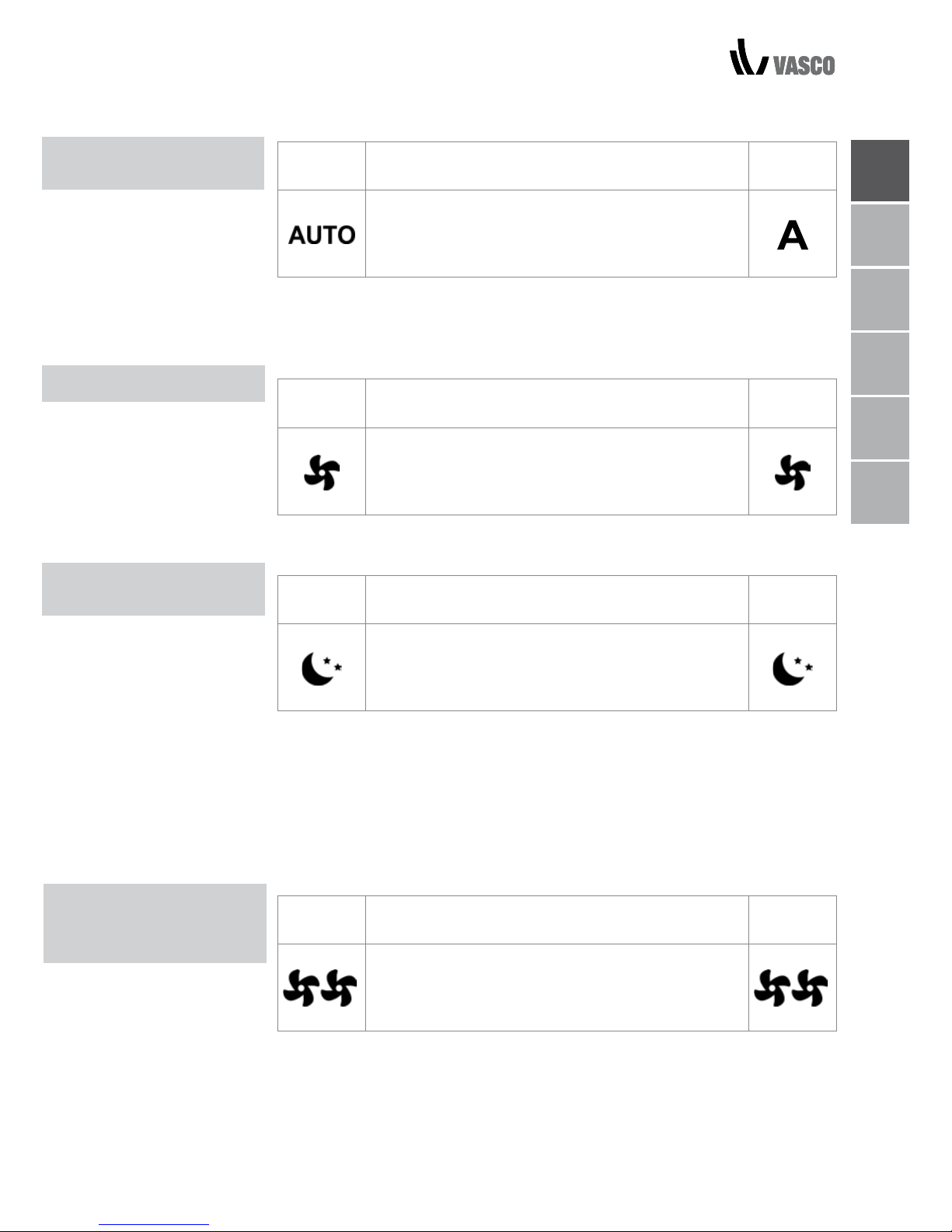
Toets Werking Display
Houd de AUTO-toets ingedrukt. De functie die
wordt geactiveerd, wordt aangegeven door het
overeenkomstige symbool op het display.
Aan de hand van een PI-algoritme wordt de ventilatiesnelheid automatisch
aangepast tussen de minimum- en maximumwaardes, op basis van het
verschil tussen de daadwerkelijke kamertemperatuur en het instelpunt.
Key Operation Display
Houd de Stil-toets ingedrukt. De functie die
wordt geactiveerd, wordt aangegeven door het
overeenkomstige symbool op het display.
Ventilatiesnelheid is beperkt tot een begrensde maximumwaarde.
Toets Werking Display
Houd de Nachtelijke werking-toets ingedrukt. De
functie die wordt geactiveerd, wordt aangegeven
door het overeenkomstige symbool op het display.
In deze modus wordt de ventilatiesnelheid beperkt tot een bepaald niveau
en wordt de ingestelde temperatuur automatisch gewijzigd op de volgende
manier:
- vermindert met 1°C na een uur en nog een graad na twee uur in
verwarmingsmodus
- stijgt met 1°C na een uur en nog een graad na twee uur in koelmodus;
Toets Werking Display
Houd de Max. werking-toets ingedrukt. De functie
die wordt geactiveerd, wordt aangegeven door het
overeenkomstige symbool op het display.
In deze werkingsmodus wordt het maximale vermogen geactiveerd bij het
verwarmen of koelen. Zodra de gewenste kamertemperatuur is bereikt, raden
wij aan om een van de andere drie werkingsmodi te selecteren voor meer
comfort en aangenamere geluidsniveaus.
Page 8
06 TOETSENVERGRENDELING / HELDERHEID VERMINDEREN / DEACTIVERING /
KAMERTEMPERATUUR REGELEN
TOETSEN
VERGRENDELING
UITSCHAKELEN
GEDURENDE LANGE
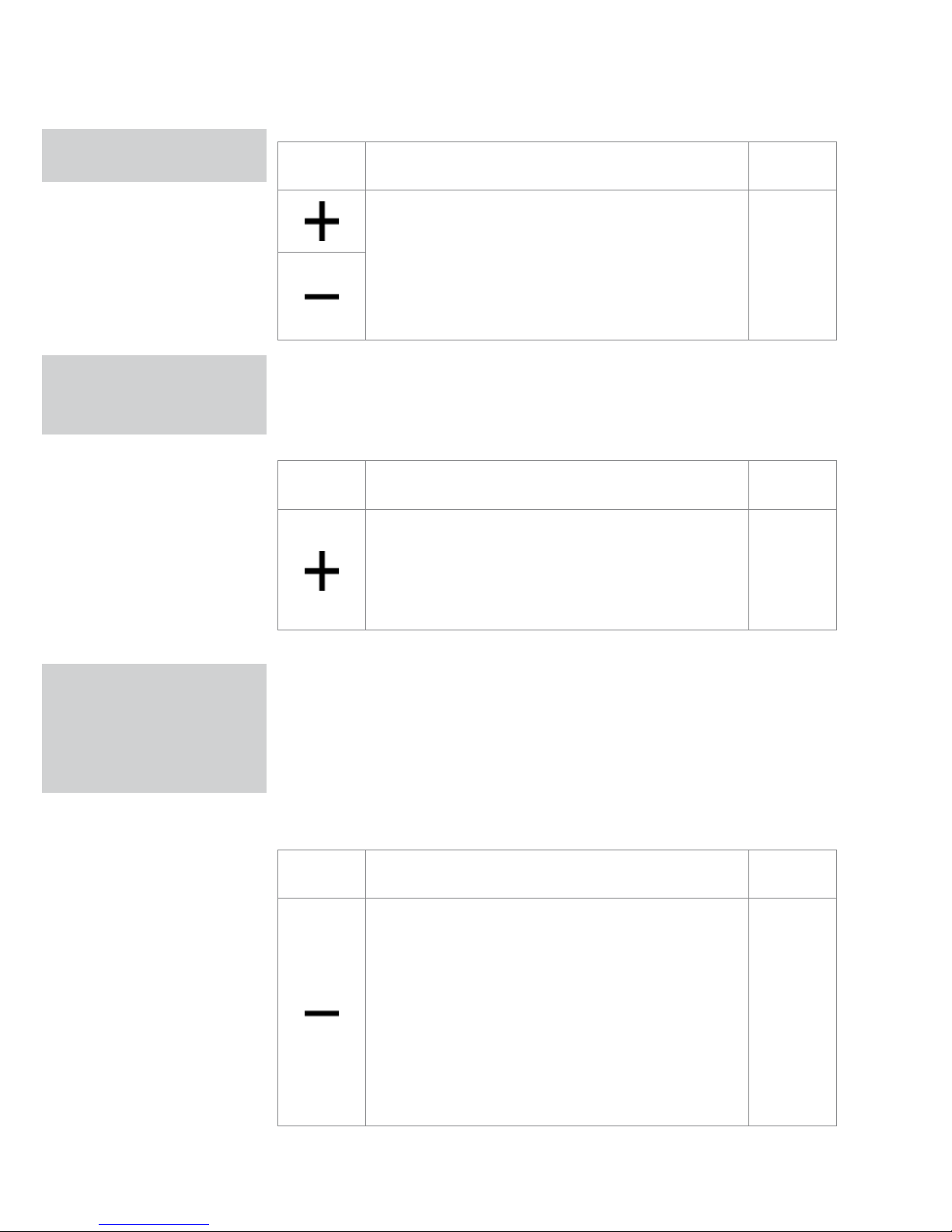
Toets Werking Display
Door de + en - toetsen drie seconden lang in te
drukken worden alle toetsen lokaal vergrendeld.
Dit wordt aangegeven op het display met “bL”.
Alle acties worden uitgeschakeld voor de gebruiker
en als er een toets wordt ingedrukt, verschijnt
“LOC” op het display. Herhaal het proces om de
toetsen te ontgrendelen.
bL
20 seconden na de laatste handeling wordt de helderheid van het paneel
verlaagd om u meer nachtelijk comfort te bieden. De kamertemperatuur
verschijnt op het display. Als u de helderheid nog steeds storend vindt, kunt u
het display volledig afsluiten.
Toets Werking Display
Houd de + toets 5 seconden lang ingedrukt als het
display uit staat totdat “01” verschijnt.
Gebruik de - toets om de waarde te veranderen
naar 00 en wacht 20 seconden om te controleren of
de instelling werd geaccepteerd.
00
Omdat de detectiesonde zich aan de onderkant van het apparaat bevindt,
kan de gedetecteerde temperatuur soms verschillen van de werkelijke
kamertemperatuur. Aan de hand van deze functie kan de weergegeven
waarde aangepast worden binnen een bereik van -9/+12 K in intervallen van
0,1 °C. Wees voorzichtig met de wijzigingsfunctie, gebruik deze alleen als u
aan de hand van een betrouwbaar apparaat een verschil heeft gedetecteerd
met de huidige kamertemperatuur.
Toets Werking Display
Wanneer het scherm is uitgeschakeld, druk op
de toets – en hou die gedurende vijf seconden
ingedrukt. Daarna verschijnt het menu waarin de
weergegeven offset van de AIR probe kan worden
veranderd (met behulp van de toetsen – en +).
U kunt voor de offset een waarde ingeven tussen
-9 en +12 K met intervallen van 0,1 K.
20 seconden nadat u de laatste handeling hebt
uitgevoerd, schakelt het paneel automatisch uit en
worden de nieuwe instellingen opgeslagen.
00.0
HELDERHEID
VERMINDEREN TOT HET
MINIMUM
OFFSET VAN DE
REGELING VAN DE
KAMERTEMPERATUUR-
SONDE
Page 9
NL
FR
DE
EN
IT
PL
UITSCHAKELEN GEDURENDE LANGE PERIODES / FOUTSIGNALEN 07
UITSCHAKELEN
GEDURENDE LANGE
PERIODES
ERROR SIGNALS
Ga als volgt te werk als u het apparaat uitschakelt voor een seizoen of als u
met vakantie gaat:
- Schakel het apparaat uit
- Schakel de hoofdschakelaar van de unit uit.
De vorstbeveiligingsfunctie is niet actief.
Error Display
Probleem met de kamertemperatuur probe (AIR).
E1
Probleem met de ventilatormotor (bijv. blokkering door
vreemde voorwerpen, defecte rotatiesensor).
E2
Fout met koudwatertemperatuursonde voor versies met
4 buizen (H4). (Enkel voor ECA647) geplaatst op de
hoofdbatterij.
E3
Activering van de roostermicroschakelaar S1 door filter te
reinigen.
Gr
Page 10
08 EXTERNE REINIGING / REINIGING VAN HET LUCHTAANZUIGINGSFILTER
EXTERNE
REINIGING
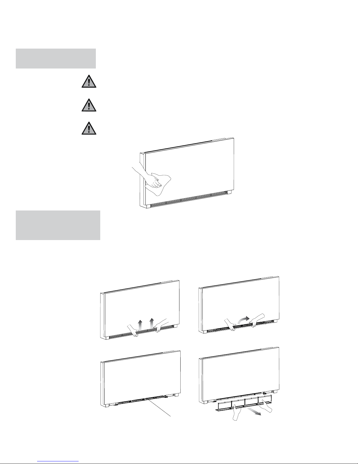
Koppel de unit los van de stroom voor elke reinigings- en onderhoudsbeurt
door de hoofdvoedingsschakelaar uit te zetten.
Wacht tot de componenten afgekoeld zijn om eventuele brandwonden te
vermijden.
Vermijd het gebruik van schuursponsen of schurende of bijtende
reinigingsmiddelen zodat u de geverfde oppervlakken niet beschadigt.
Reinig indien nodig de externe oppervlakken van de ventilatorconvector met
een zachte, vochtige doek.
Reinig het luchtfilter na een periode van continu gebruik afhankelijk van de
concentratie van onzuiverheden in de lucht of als u het apparaat opnieuw wilt
inschakelen na een periode van inactiviteit. Ga als volgt te werk.
FILTERCELLEN VERWIJDEREN
- haal de filter uit het apparaat door omhoog te tillen en te kantelen.
2 ONDERHOUD
REINIGING VAN DE
LUCHTAANZUIGINGS-
FILTER
filter extraction
A
B
C
D
Page 11
NL
FR
DE
EN
IT
PL
REINIGING VAN DE FILTERS / SUGGESTIES OM ENERGIE TE BESPAREN 09
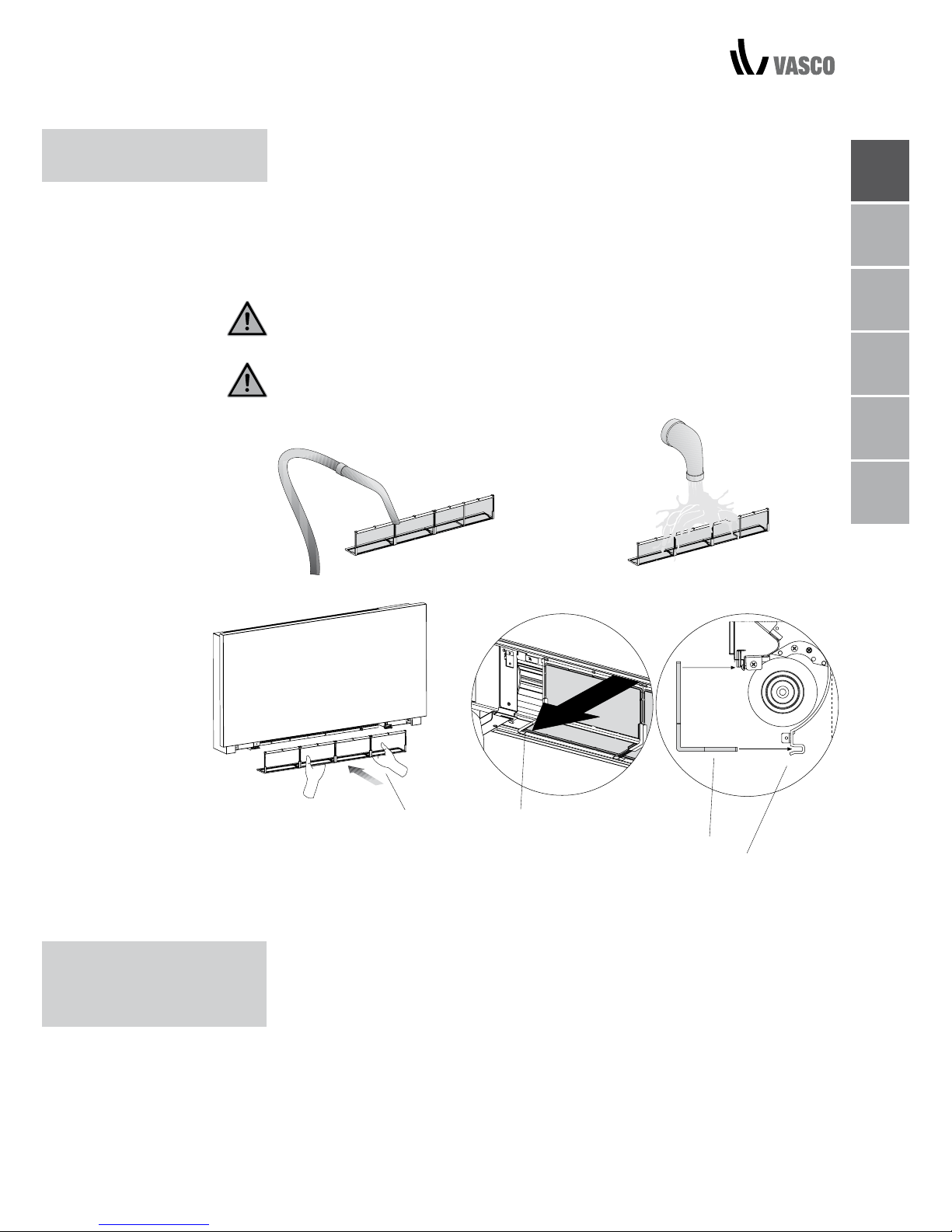
A filter
B onderste rand
C filterbehuizing
- Verwijder stof uit de filter met een stofzuiger
- Was de filter onder stromend water zonder reinigingsproducten
of oplosmiddel te gebruiken, en laat het drogen.
- Plaats de filter terug op zijn plaats op de ventilatorconvector en let hierbij
op dat u de onderste rand in de behuizing plaatst.
Gebruik het apparaat niet zonder het gaasfilter.
Het apparaat is uitgerust met een veiligheidsschakelaar die voorkomt dat de
ventilator werkt zonder dat het rooster op zijn plaats zit.
Controleer na de reiniging van het filter of het rooster correct gemonteerd is.
REINIGING
VAN DE FILTERS
Zorg ervoor dat de filters altijd schoon zijn.
Houd deuren en ramen in de mate van het mogelijke gesloten in ruimtes die
geconditioneerd moeten worden.
Beperk het zonlicht zo veel mogelijk in ruimtes die geconditioneerd moeten
worden (met gordijnen, rolluiken etc.)
SUGGESTIES
OM ENERGIE TE
BESPAREN
A
B
B
C
Page 12

10 PROBLEMEN OPLOSSEN
3 PROBLEMEN OPLOSSEN
PROBLEMEN
OPLOSSEN
Als er water lekt of als het apparaat abnormaal functioneert, koppel dan de
stroomtoevoer onmiddellijk los en sluit alle waterkranen.
Neem contact op met een erkend servicecentrum of een bevoegde
gekwalificeerde persoon indien zich een van volgende storingen voordoet.
Laat het apparaat zoals het is.
- De ventilatie start niet op, zelfs niet als er warm of koud water in het
hydraulisch circuit zit.
- Er lekt water uit het apparaat tijdens het verwarmen.
- Er lekt enkel tijdens het koelen water uit het apparaat.
- Het apparaat maakt overdreven veel lawaai.
- Er vormt zich vocht op het voorpaneel.
Page 13
NL
FR
DE
EN
IT
PL
OPLOSSEN
PROBLEMEN
TABEL MET STORINGEN EN OPLOSSINGEN 11
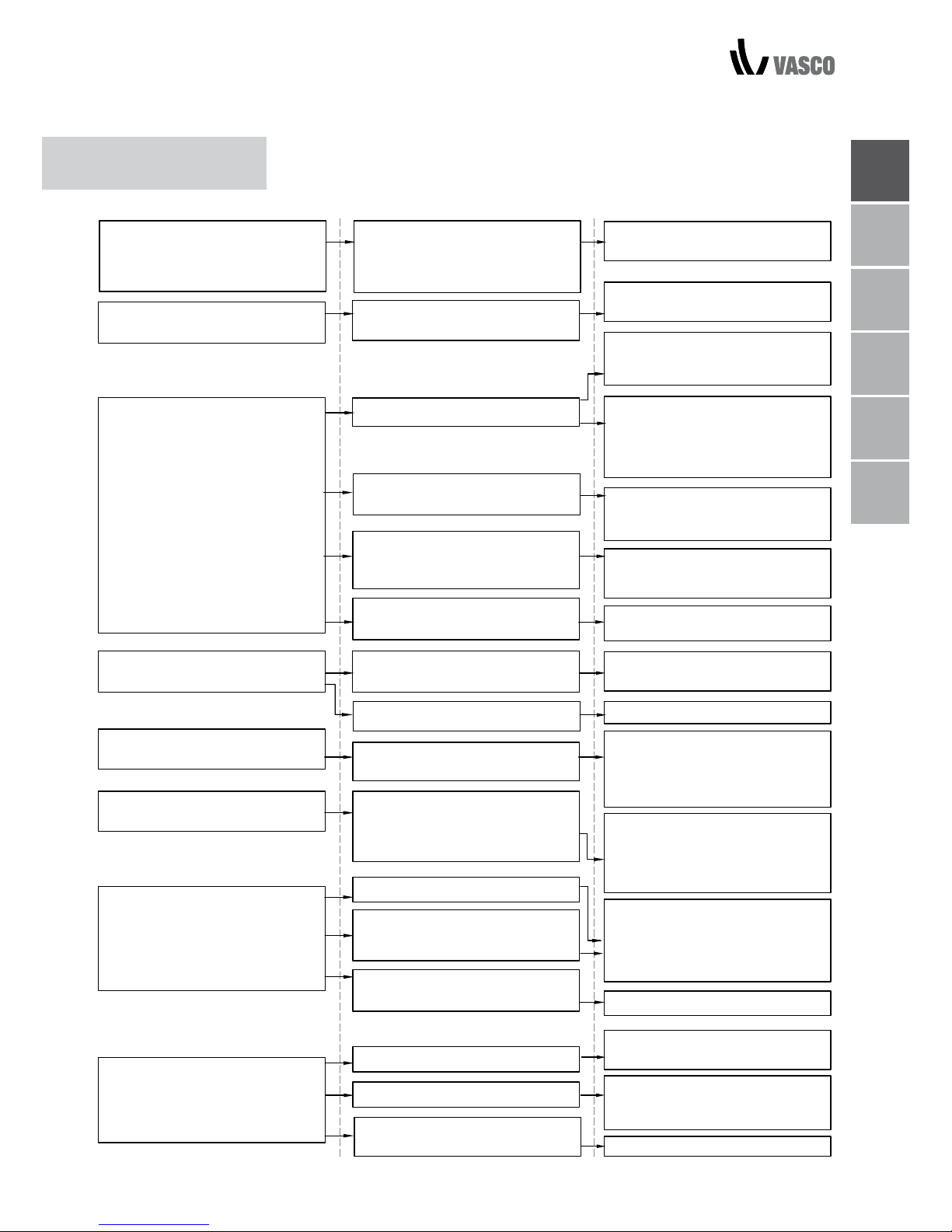
EFFECT OORZAAK OPLOSSING
De klep heeft tijd nodig om te
openen, bijgevolg duurt het even
vooraleer er koud of warm water
circuleert in het apparaat.
Geef de klep 2 of 3 minuten tijd
om te openen.
Een vertraagde activering van de
ventilatie met betrekking tot de
nieuwe temperatuurs- of functieinstellingen.
Geen koud of warm water in het
systeem.
De hydraulische klep blijft gesloten.
Ga na of de boiler en koeler
correct functioneren.
Demonteer de klepbehuizing
en ga na of het water opnieuw
circuleert.
Het apparaat activeert de ventilatie
niet.
De ventilatie start niet op, zelfs niet
als er warm of koud water in het
hydraulisch circuit zit.
Controleer de werking van de klep
door deze afzonderlijk te voorzien
van 230V/AC. Als de klep opstart,
kan het probleem bij de elektronische regelaar liggen.
De ventilatormotor is geblokkeerd
of oververhit.
Controleer motorwikkelingen en
of de ventilator ongehinderd kan
draaien.
De microschakelaar die de ventilatie stopzet als het filterrooster geopend is, sluit niet naar behoren.
Ga na of het microschakelaarcontact geactiveerd wordt als u
het rooster sluit.
De elektrische verbindingen zijn
niet correct.
Controleer de elektrische
verbindingen.
Er zijn lekken in de hydraulische
verbindingen van het systeem.
Ga op zoek naar lekken en span
de verbindingen aan.
Er lekt water uit het apparaat
tijdens het verwarmen.
Er zijn lekken in de klep-unit.
Controleer de dichtingen.
Ga na of de thermo-akoestische
isolatie correct geplaatst is met
speciale aandacht voor die aan
de voorkant boven de vleugelbatterij.
Er vormt zich vocht op het voorpaneel.
De thermische isolatie is losgekomen.
Zodra de vochtigheid daalt,
verdwijnt het fenomeen. Een paar
waterdruppels in het apparaat
betekenen nog niet dat er een
storing is.
Er zijn waterdruppels aanwezig op
het luchtuitlaatrooster.
In zeer vochtige omstandigheden
(>60%) kan er condens optreden,
vooral bij minimale ventilatiesnelheden.
Giet traag een fles water in het
onderste deel van de batterij om
de afvoer te controleren. Reinig de
schaal en/of vergroot de helling
van de afvoerbuis indien nodig.
Er lekt enkel tijdens het koelen
water uit het apparaat.
De condensschaal is geblokkeerd.
De condensafvoer heeft geen
helling nodig om correct te
functioneren.
De verbindingsbuizen en klep-unit
zijn niet goed geïsoleerd.
Controleer de isolatie van de buizen.
Het apparaat maakt een vreemd
geluid.
De ventilator raakt de structuur.
De ventilator is uit evenwicht.
Ga na of de filters verstopt zijn en
reinig ze indien nodig
Ga na of de filters verstopt zijn en
reinig ze indien nodige.
De onbalans zorgt voor
overmatige vibraties van de
machine, vervang de ventilator.
Reinig de filters.
Page 14

12 GARANTIEVOORWAARDEN
4 GARANTIEVOORWAARDEN
Vasco verklaart hierbij garantie te verlenen op de Vasco Niva FC gedurende 2 jaar
na de aankoopdatum. De factuurdatum van het installatiebedrijf geldt als bewijs
van aankoopdatum. Indien er geen factuur voorhanden is, geldt de productiedatum als aankoopdatum. De garantie omvat enkel de vervanging van reserveonderdelen, de ventilator en het elektronicaprint. Er is geen extra garantieperiode
voorzien op reserveonderdelen.
De garantie heeft géén betrekking op:
• Demontage- en montagekosten
• Gebreken die naar ons oordeel het gevolg zijn van onjuiste behandeling,
onachtzaamheid of een ongeluk
• Gebreken die ontstaan zijn door behandeling of herstel door derden zonder
onze toestemming
• Gebreken die het gevolg zijn van niet-regelmatig en/of onvakkundig
onderhoud
• Gebreken die het gevolg zijn van gebruik in een niet geschikte omgeving.
Er zal geen garantie verleend worden indien de FCU wordt gebruikt in deze
omschreven omstandigheden. Voor de retourzending van de defecte onderdelen
moet de installateur contact opnemen met Vasco. De installateur ontvangt dan een
garantieretournummer. De defecte onderdelen moeten onder vermelding van dit
retournummer worden verzonden naar Vasco.
Kruishoefstraat 50
B-3650 Dilsen
T. +32 (0)89 79 04 11
F. +32 (0)89 79 05 00
[email protected]
www.vasco.eu
FABRIKANTENVERKLARING
Vasco verklaart dat de FCU het CE-label draagt en is ontworpen, geproduceerd en gecommercialiseerd in overeenkomst met volgende EEC-normen:
Laagspanningsrichtlijn 2014/35/EU met de volgende technische normen:
EN 60335-2-40:2003 + A11:2004 + A12:2005 + A1:2006 + EC:2006
+ A2:2009 + A13:2012 + A13/EC:2013, EN 60335-1:2002 + A11:2004
+ A1:2004 + A12:2006 + A2:2006+ A1/EC:2007 + A13:2008 + EC:2009
+ EC:2010 + A14:2010 + A15:2011
EMC-richtlijn 2014/30/EU met volgende technische normen:
EN 60335-1:2012, EN 55014-1:2006 + A1:2009 + A2:2011,
EN 61000-3-2:2006 + A1:2009 + A2:2009, EN 61000- 3-3:2013,
EN 55014-2:1997 + A1:2001 + A2:2008
RoHS-richtlijn 2011/65/EU
Vasco Group nv
Dilsen, België, augustus 2017
P. Nijs, CEO
Page 15
NL
FR
DE
EN
IT
PL
1 GÉNÉRALITÉS
Panneau électronique 2
Écran 2
Fonction des touches 3
Allumage général 3
Activation 3
Conguration du mode de fonctionnement chauffage/refroidissement 4
Mode veille 4
Sélection de la température 4
Fonctionnement automatique 5
Fonctionnement silencieux 5
Fonctionnement de nuit 5
Fonctionnement à une vitesse de ventilation maximale 5
Verrouillage des touches 6
Réduction optimale de l’éclairage 6
Désactivation 6
Offset de réglage de la sonde de température ambiante 6
Arrêt pour de longues périodes 7
Signaux d’erreur 7
2 ENTRETIEN
Nettoyage externe 8
Nettoyage du ltre d’aspiration d’air 8
Nettoyage des ltres 9
Suggestions pour économiser l’énergie 9
3 RÉSOLUTION DES PANNES
Résolution des pannes 10
Tableau de résolution des pannes 11
4 CONDITIONS DE GARANTIE
Conditions de garantie 12
TABLE DES MATIÈRES
TABLE DES MATIÈRES 01
Page 16
02 CONFORMITÉ / SYMBOLES / TABLE DES MATIÈRES
ÉLECTRONIQUE
Ce radiateur est conforme aux directives européennes:
• directive basse tension 2014/35/EU
• compatibilité électromagnétique 2014/30/EU
Les pictogrammes du chapitre suivant fournissent, rapidement et sans
ambiguïté, les informations nécessaires à une utilisation correcte
et sûre du radiateur.
SAFETY PICTOGRAMS
Danger général
Signale au personnel que l’opération décrite est susceptible de provoquer des
blessures corporelles, si elle n’est pas effectuée conformément aux règles de
sécurité.
Danger de haute tension
Signale au personnel que l’opération décrite est susceptible de provoquer un
risque d’électrocution si elle n’est pas effectuée, conformément aux règles de
sécurité.
Danger dû à la chaleur
Signale au personnel que l’opération décrite est susceptible de provoquer des
brûlures si elle n’est pas effectuée, conformément aux règles de sécurité.
Interdiction
Signale les actions les actions et manipulations, à proscrire absolument.
CONFORMITÉ
SYMBOLES
Page 17
NL
FR
DE
EN
IT
PL
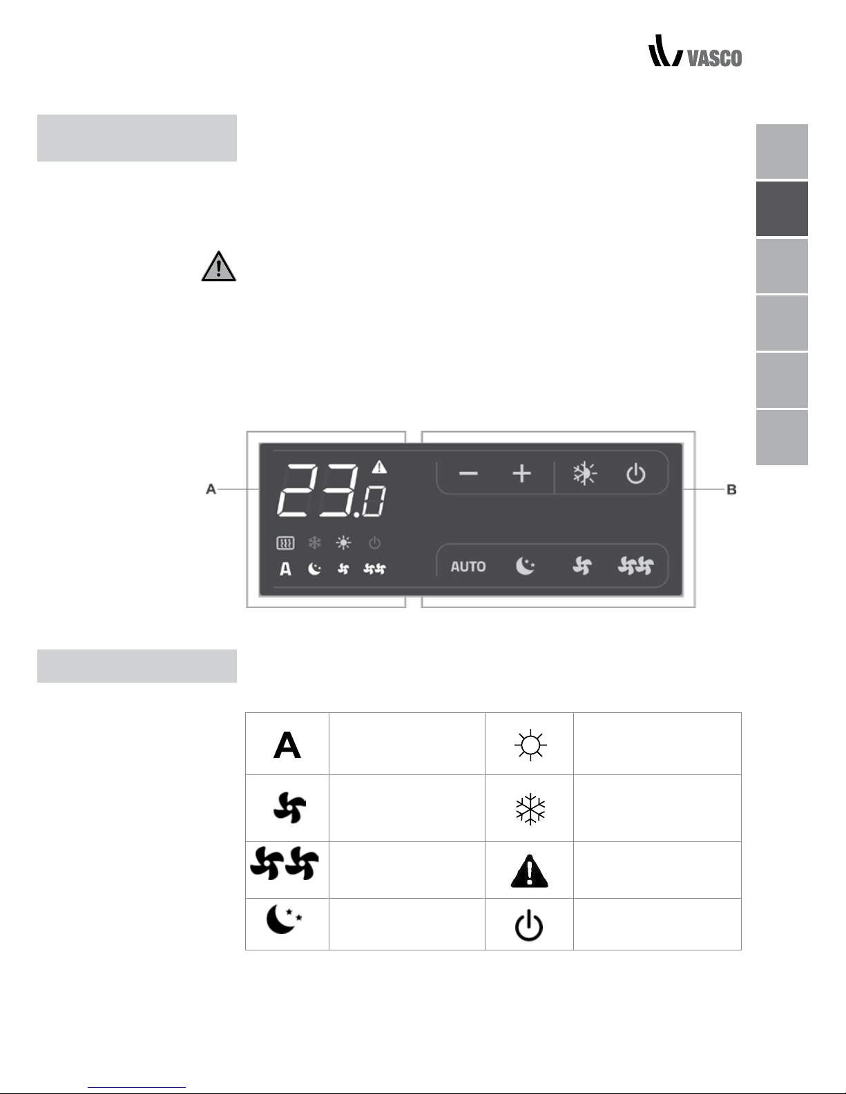
Cette commande rend complètement autonome le réglage de la température
ambiante (offset réglable à partir du clavier) grâce aux programmes AUTO,
SILENT, NIGHT et MAX, et ce, au moyen d’une sonde située dans la partie
inférieure de l’appareil, ce qui garantit une sécurité antigel même en mode
veille. Le panneau de contrôle dispose d’une mémoire. Les paramètres ne
sont donc pas perdus en cas d’arrêt de l’appareil ou de panne de courant.
Vingt secondes après la dernière action, l’éclairage du panneau faiblit
pour augmenter le confort durant les heures nocturnes et l’écran affiche la
température ambiante. Appuyez sur n’importe quelle touche pour rétablir
l’éclairage maximal.
La sonde 10 kΩ de détection de la température de l’eau, située à l’intérieur de
la batterie, règle le niveau minimal en chauffage (28 °C) et le niveau maximal en
refroidissement (20 °C).
Les états et alarmes s’affichent aussi à l’écran à l’aide de 8 symboles
spécifiques:
Fonctionnement
automatique
Chauffage actif
Fonctionnement
silencieux
Refroidissement actif
Vitesse de ventilation
maximale
Témoin d’alarme
(voyant fixe)
Fonctionnement de
nuit
Panneau de commande
éteint
1 GÉNÉRALITÉS
PANNEAU
ÉLECTRONIQUE
ÉCRAN
PANNEAU ÉLECTRONIQUE / ÉCRAN 03
A Écran
B Touches
Page 18
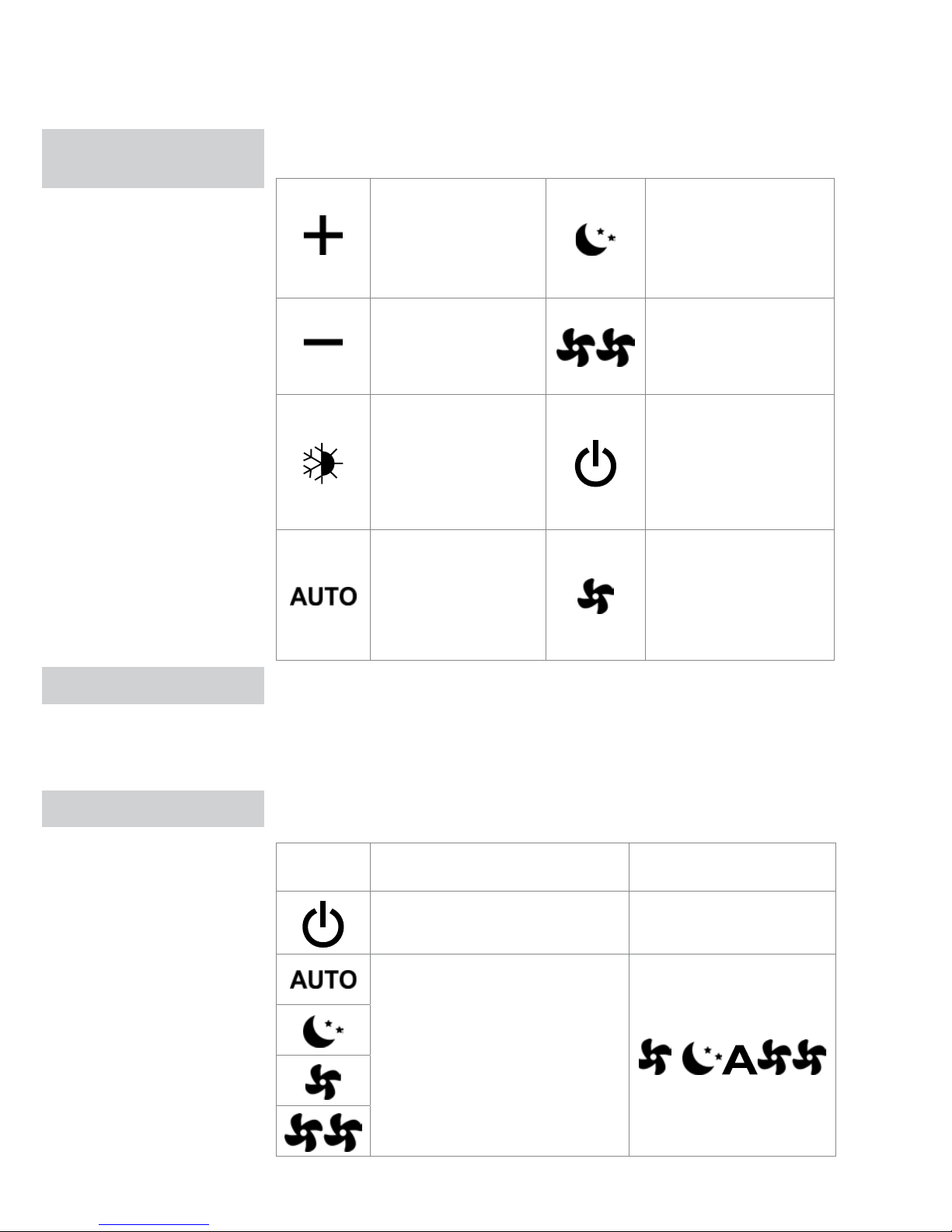
Les différentes fonctions se configurent au moyen de 8 touches rétroéclairées:
Temp
+ permet d’augmenter
la température
configurée
Fonctionnement de nuit:
limite la vitesse de ventilation à un niveau contenu
et ajuste automatiquement
la température réglée
Temp
- permet de diminuer la
température configurée
Fonctionnement à vitesse
maximale : permet un
réglage de la vitesse de
ventilation maximale
Chauffage refroidissement: permet de
commuter le mode de
fonctionnement entre
chauffage et refroidissement
ON/Veille : pour allumer
l’appareil ou le mettre en
mode veille
Règle la vitesse de
ventilation régulée entre
une valeur minimale et
une valeur maximale sur
un mode entièrement
automatique
Silencieux : limite la
vitesse de ventilation à
une valeur plus contenue
Pour piloter l’appareil au moyen du panneau de commande, le radiateur doit
être raccordé au réseau électrique. Si un interrupteur général a été prévu sur la
ligne d’alimentation électrique, celui-ci doit aussi être allumé.
- Allumez l’appareil en activant l’interrupteur général.
Pour activer l’appareil
Touche Opération Écran
Enfoncez la touche ON/Veille S’allume
Sélectionnez l’un des 4 modes de
fonctionnement en appuyant sur la
touche correspondante.
FONCTION
DES TOUCHES
ALLUMAGE GÉNÉRAL
ACTIVATION
04 FONCTION DES TOUCHES / ALLUMAGE GÉNÉRAL / ACTIVATION
Page 19
NL
FR
DE
EN
IT
PL
CONFIGURATION
DU MODE DE
FONCTIONNEMENT
CHAUFFAGE/
REFROIDISSEMENT
MODE VEILLE
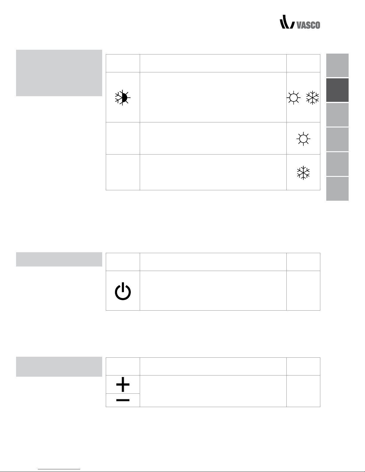
Touche Opération Écran
Appuyez sur la touche chauffage/refroidissement
pendant 2 secondes environ pour choisir le mode
de fonctionnement (chauffage ou refroidissement),
visible grâce aux 2 symboles qui s’affichent quand
l'un ou l'autre des modes est actif.
En mode chauffage, le symbole s’affiche lorsque
le point de consigne est supérieur à la température
ambiante, Les deux voyants sont éteints lorsque le
point de consigne est inférieur.
Lors du refroidissement, le symbole s’affiche
lorsque le point de consigne est inférieur à la
température ambiante. Les deux voyants sont
éteints lorsque le point de consigne est supérieur.
Le clignotement de l’un des 2 symboles indique que la température de l’eau
(chaude ou froide) n’est pas suffisante; le ventilateur s’arrête jusqu’à ce que
la température atteigne une valeur adéquate pour répondre à la demande. Si
après la mise sous tension, la sonde de température de l’eau est détectée, le
démarrage a lieu dans des conditions normales avec les seuils minimum et
maximum. La carte a également une fonction quand il n’y a pas de sonde de
température de l’eau. Dans ce cas, les seuils d’arrêt du ventilateur sont ignorés.
Touche Opération Écran
Appuyez sur la touche ON/Veille pendant 2
secondes environ. L’absence totale de signal
lumineux à l’écran, indique que le système est en
veille (absence de fonctionnement).
Off
Dans ce mode de fonctionnement, le mode antigel est garanti quoi qu’il
arrive. Si la température ambiante descend en dessous de 5 °C, les
électrovannes au niveau de l’eau chaude sanitaire et de la chaudière s'ouvrent
automatiquement..
Touche Opération Écran
Configurez la température ambiante souhaitée à
l’aide des touches + et -. La température réglée
s’affiche sur l’écran à 3 chiffres.
20.5
La plage de réglage va de 16 à 28 °C par intervalles de 0,5 °C, mais les
valeurs hors plage sont également acceptées, de 5 °C à 40 °C (sauf en mode
automatique). Configurez ces valeurs pour de courtes périodes uniquement,
puis paramétrez une valeur intermédiaire.
TEMPERATURE
SELECTION
CONFIGURATION DU MODE / MODE VEILLE / TEMPERATURE SELECTION 05
Page 20
06
FONCTIONNEMENT AUTOMATIQUE / SILENCIEUX / DE NUIT
/ À VITESSE
FONCTIONNEMENT
AUTOMATIQUE
FONCTIONNEMENT
SILENCIEUX
FONCTIONNEMENT
DE NUIT
FONCTIONNEMENT À
VITESSE DE
VENTILATION MAXIMALE
La commande est très précise ; réglez-la sur la valeur souhaitée et attendez
que la commande se règle automatiquement en fonction de la température
ambiante réellement détectée.
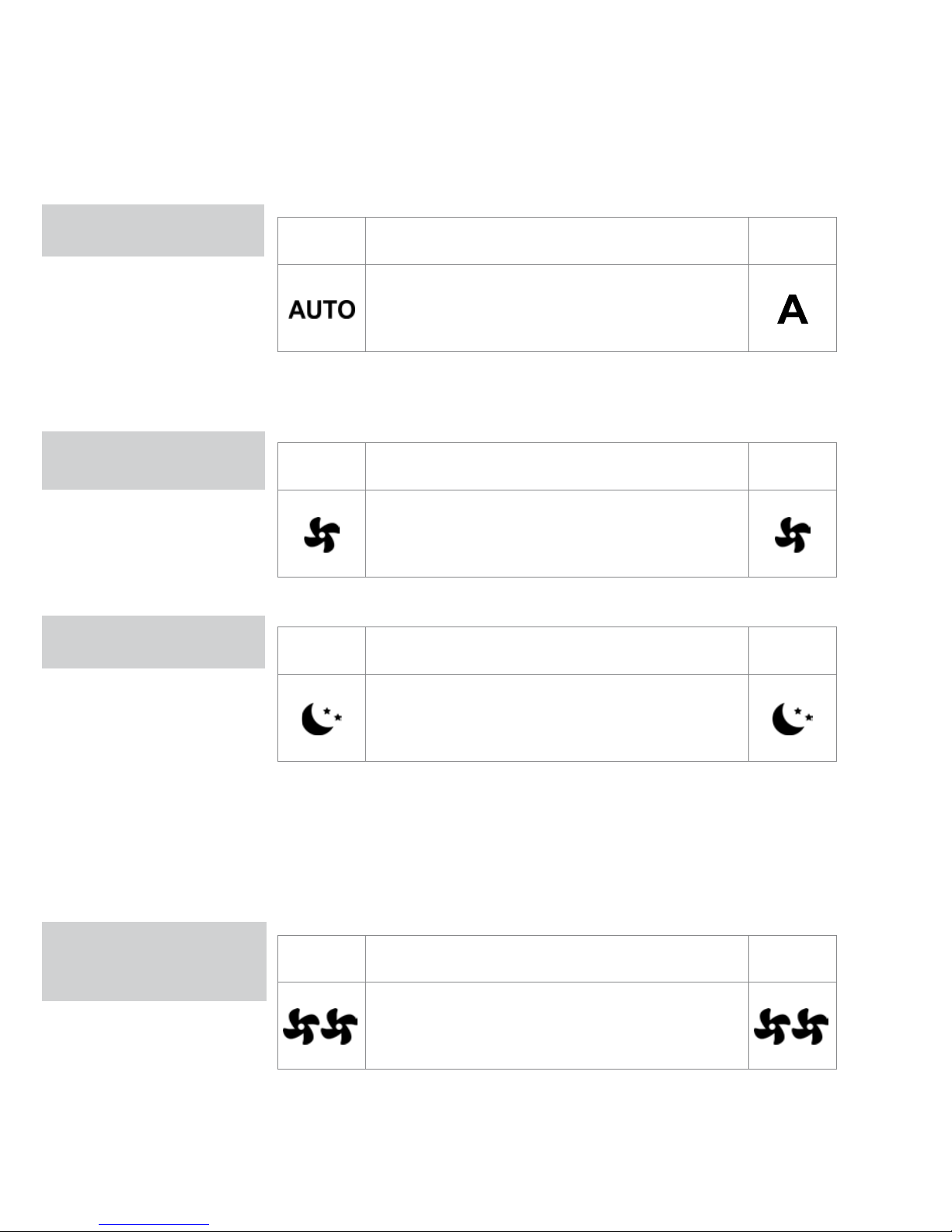
Touche Opération Écran
Maintenez la touche AUTO enfoncée. La fonction
activée est signalée par l’allumage du symbole
correspondant à l’écran.
Le réglage de la vitesse de ventilation s’effectue automatiquement entre les
valeurs minimale et maximale, en fonction de l’écart entre la température
ambiante réelle et le point de consigne, selon un algorithme de type PI.
Touche Opération Écran
Maintenez la touche SILENT enfoncée. La fonction
activée est signalée par l’allumage du symbole
correspondant à l’écran.
La vitesse de ventilation est limitée à une valeur maximale contenue.
Touche Opération Écran
Maintenez la touche NIGHT enfoncée. La fonction
activée est signalée par l’allumage du symbole
correspondant à l’écran.
Lorsque ce mode est sélectionné, la vitesse de ventilation est limitée à
un niveau extrêmement contenu et la température configurée est ajustée
automatiquement, comme suit:
- diminution de 1 °C après une heure et d’un degré supplémentaire après
deux heures en mode chauffage;
- augmentation de 1 °C après une heure et d’un degré supplémentaire après
deux heures en mode refroidissement.
Touche Opération Écran
Maintenez la touche MAX enfoncée. La fonction
activée est signalée par l’allumage du symbole
correspondant à l’écran.
Avec ce mode, on obtient la puissance maximale aussi bien en chauffage
qu’en refroidissement. Une fois que la température ambiante souhaitée
est atteinte, il est conseillé de sélectionner l’un des 3 autres modes de
fonctionnement pour accroître le confort thermique et acoustique.
Page 21
NL
FR
DE
EN
IT
PL
VERROUILLAGE DES TOUCHES / RÉDUCTION DE L’ÉCLAIRAGE / RÉGLAGE DE LA TEMPÉRATURE
07
VERROUILLAGE DES
TOUCHES
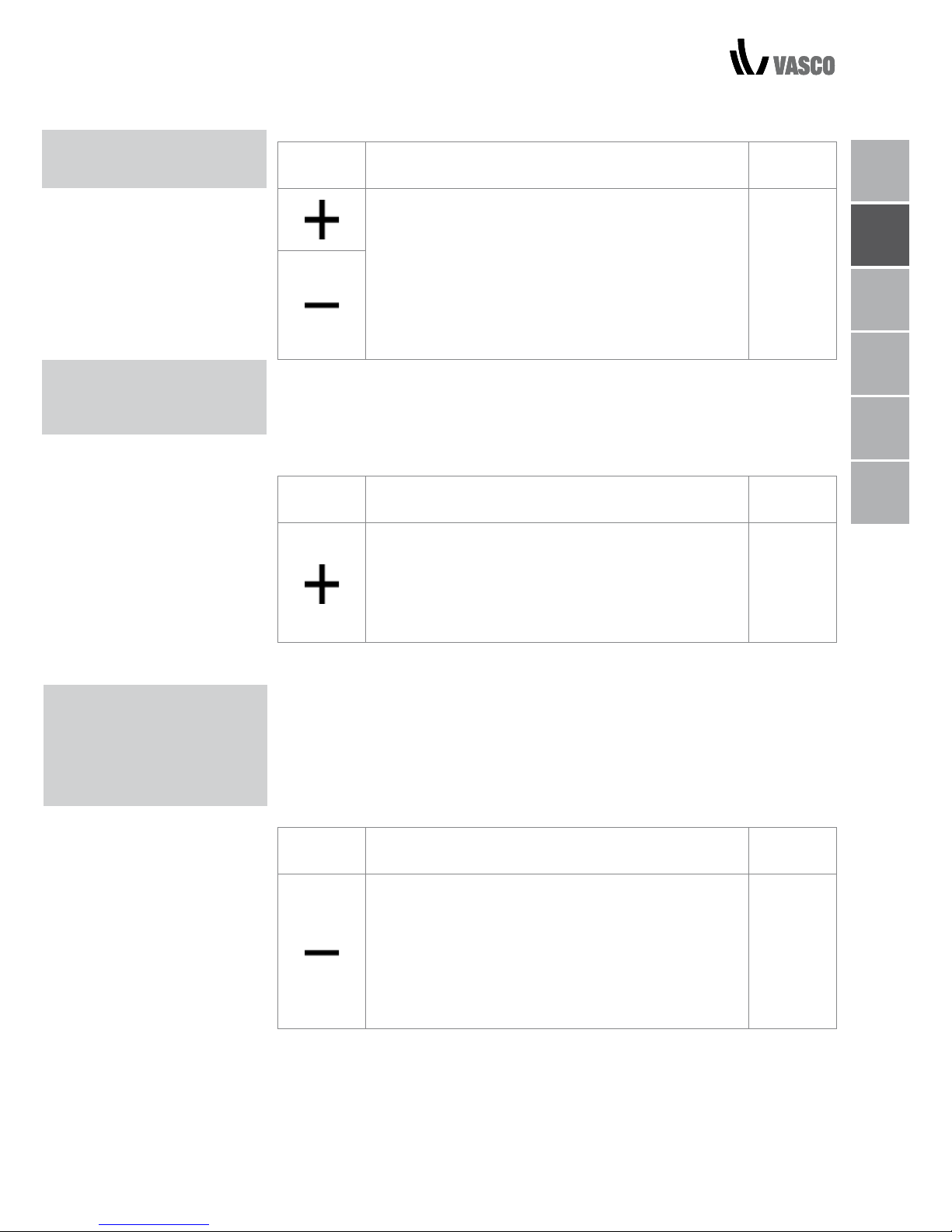
Touche Opération Écran
Si vous appuyez simultanément sur les touches + et
- pendant 3 secondes, le verrouillage local de toutes
les touches s’active, le verrouillage local de toutes
les touches s'active : la mention "BL" s'affiche alors
à l'écran. L’utilisateur ne peut plus effectuer de
réglage et la mention "Loc" apparaît, lorsqu'il appuie
sur l'une des touches. Répétez la séquence pour
débloquer les touches.
bL
Vingt secondes après la dernière action, l’éclairage du panneau faiblit
pour augmenter le confort durant les heures nocturnes et l’écran affiche la
température ambiante. Si cet éclairage vous dérange, il est possible d’éteindre
complètement l’écran.
Touche Opération Écran
Lorsque l’écran est éteint, maintenez la touche +
enfoncée pendant 5 secondes, jusqu’à ce que « 01
» s’affiche. Utilisez la touche - pour remplacer cette
valeur par 00 et attendez 20 secondes pour vous
assurer que la configuration a bien été acceptée.
00
Comme la sonde de détection se trouve dans le bas de l’appareil, la
température détectée peut parfois différer de la température ambiante réelle.
Grâce à cette fonction, la valeur affichée peut être réglée dans une plage de
-9/+12 K par intervalles de 0,1 °C. Utilisez ce réglage avec précaution, et
seulement après avoir détecté une anomalie par rapport à la température
ambiante réelle, à l’aide d’un appareil fiable !
Touche Opération Écran
Lorsque l’écran est éteint, maintenez la touche
- enfoncée pendant 5 secondes pour accéder
au menu de réglage (à l’aide des touches + et -)
de l’offset de la sonde AIR: de -9 à +12 K, par
intervalles de 0,1K.
Le panneau s’éteint et le paramètre est enregistré
20 secondes après la dernière action.
00.0
RÉDUCTION DE
L’ÉCLAIRAGE AU
MINIMUM
OFFSET DE
RÉGLAGE DE LA
SONDE DE
TEMPÉRATURE
AMBIANTE
Page 22
08 ARRÊT POUR DE LONGUES PÉRIODES / SIGNAUX D’ERREUR
ARRÊT POUR DE
LONGUES PÉRIODES
SIGNAUX D’ERREUR
En cas d’arrêts d’arrêts ponctuels ou d’absence prolongée, procédez comme
suit:
- désactivez l’appareil ;
- placez l’interrupteur général du radiateur sur « OFF ».
La fonction antigel est désactivée.
Erreur Écran
Sonde de température ambiante (AIR) en panne.
E1
Problème au niveau du moteur du ventilateur (p. ex.:
bourrage dû à des corps étrangers, défaillance du
capteur de rotation).
E2
Problème de sonde de température de l’eau pour les
versions à 2 tubes (H2). Assurez-vous que la sonde
installée soit de type 10 kΩ.
E3
Engagement du micro-interrupteur S1, de la grille dû à
une opération de nettoyage du filtre.
Gr
Page 23
NL
FR
DE
EN
IT
PL
NETTOYAGE EXTERNE / NETTOYAGE DU FILTRE D’ASPIRATION D’AIR 09
NETTOYAGE
EXTERNE
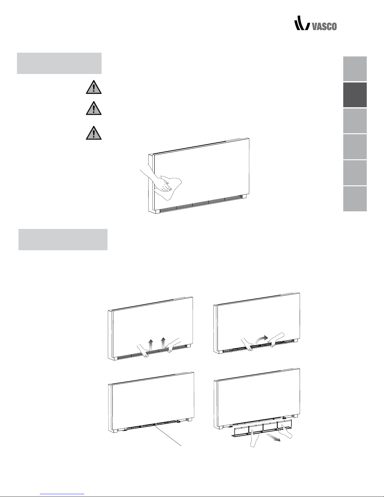
Avant toute intervention de nettoyage et d’entretien, débranchez le radiateur
du secteur en désactivant l’interrupteur général d’alimentation.
Attendez le refroidissement des composants, pour éviter tout risque de brûlure.
N’utilisez pas d’éponges abrasives ni de détergents abrasifs ou corrosifs pour
ne pas endommager les surfaces peintes.
Si nécessaire, nettoyez les surfaces externes du ventilateur à l’aiden d’un
chiffon doux et humide.
Nettoyez le filtre à air à intervalles réguliers, (selon la concentration d’impuretés
contenues dans l’air) après une longue période de fonctionnement en
continu ou lorsque vous rallumez le radiateur au terme, d’une longue période
d’inactivité. Suivez la procédure décrite ci-après.
RETRAIT DES CELLULES FILTRANTES
- Retirez le filtre en tirant horizontalement vers l’extérieur.
2 ENTRETIEN
NETTOYAGE DU FILTRE
D’ASPIRATION D’AIR
filtre extraction
A
B
C
D
Page 24
10 NETTOYAGE DES FILTRES / SUGGESTIONS POUR ÉCONOMISER L’ÉNERGIE
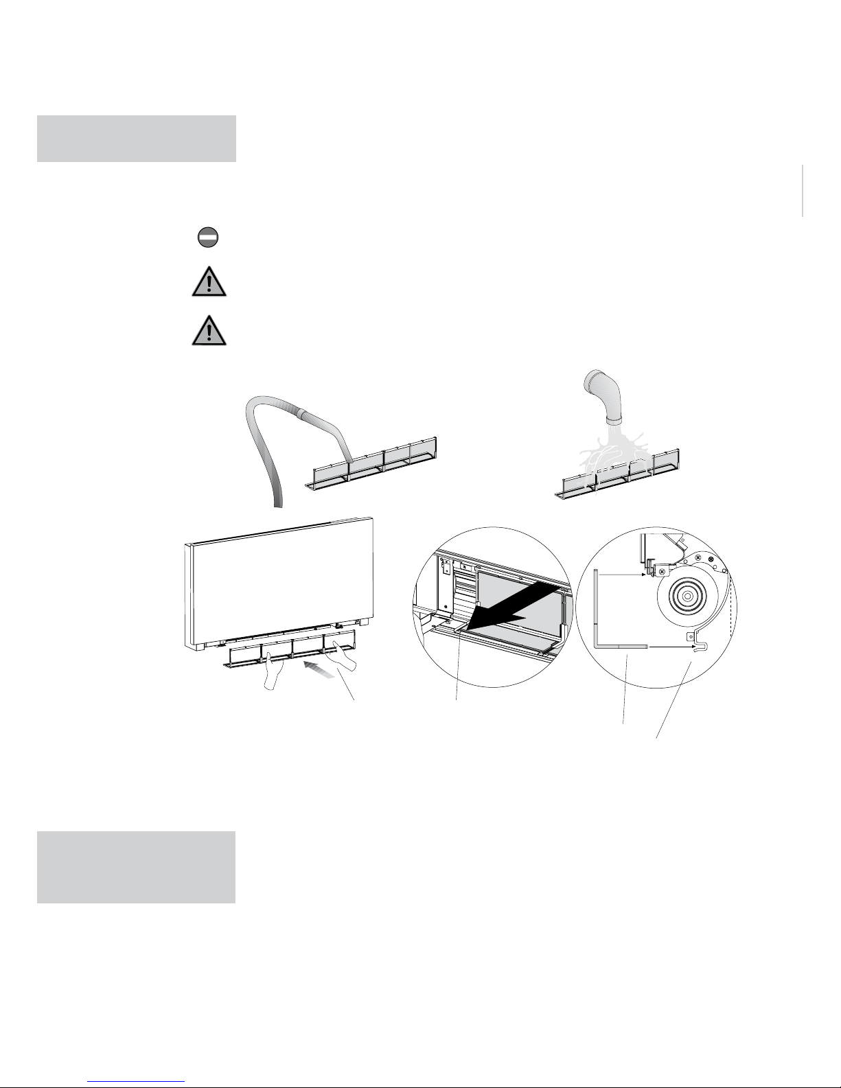
A filtre
B bord inférieur
C logement du filtre
- Aspirez la poussière du filtre avec un aspirateur.
- Lavez le filtre à l'eau claire, sans utiliser de produits nettoyants ou de
solvants. Laissez sécher.
- Remontez le filtre sur le ventilo-convecteur, en veillant à insérer
précisément le bord inférieur dans son logement.
Il est interdit d’utiliser l’appareil sans le filtre à treillis.
L’appareil est doté d’un interrupteur de sécurité qui empêche le fonctionnement
du ventilateur en l’absence d’une grille.
Une fois le filtre nettoyé, vérifiez le montage du panneau.
NETTOYAGE
DES FILTRES
- Gardez les filtres propres en permanence.
- Dans la mesure du possible, laissez les portes et les fenêtres fermées dans
les pièces à climatiser.
- En été, limitez au maximum, l'exposition directe aux rayons du soleil et
privilégiez les rideaux, stores et systèmes d'occultation.
SUGGESTIONS
POUR ÉCONOMISER
L’ÉNERGIE
A
B
B
C
Page 25
NL
FR
DE
EN
IT
PL
3 RÉSOLUTION DES PANNES
RÉSOLUTION
DES PANNES
En cas de fuites d’eau ou de fonctionnement anormal, coupez immédiatement
l’alimentation électrique et fermez les robinets d’eau.
Si vous constatez l’une des anomalies suivantes, contactez un centre
d’assistance agréé ou un professionnel qualifié. N’intervenez pas
personnellement.
- La ventilation ne s’active pas même s’il y a de l’eau chaude ou froide dans
le circuit hydraulique.
- L’appareil perd de l’eau en mode « chauffage ».
- L’appareil perd de l’eau uniquement en mode « refroidissement ».
- L’appareil émet un bruit excessif.
- De la buée se forme sur le panneau frontal.
RÉSOLUTION DES PANNES 11
Page 26
12 TABLEAU DE RÉSOLUTION DES PANNES
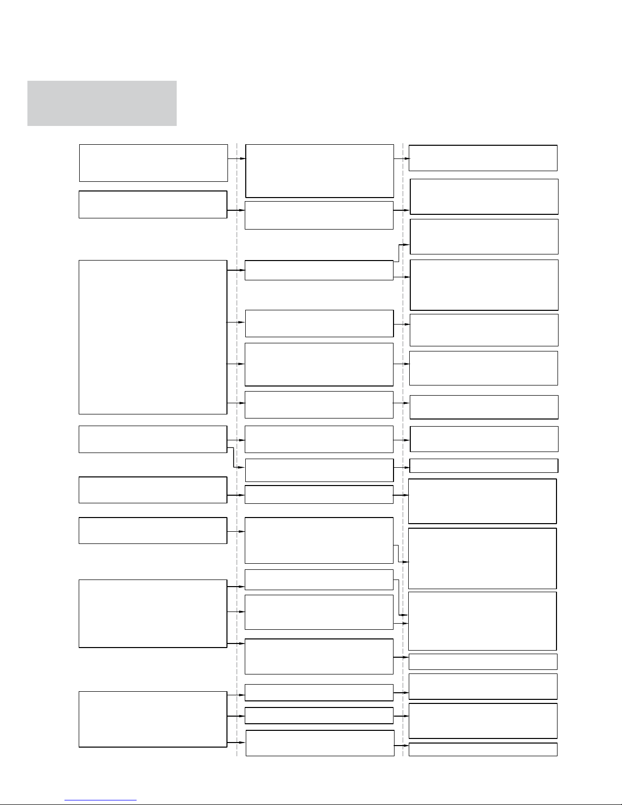
EFFET CAUSE SOLUTION
L’ouverture de la valve du circuit
requiert un certain temps. Un
délai normal est nécessaire afin
que l’eau chaude ou froide circule
dans l’appareil.
Attendez 2 ou 3 minutes l’ouverture de la valve du circuit.
La ventilation s’active en retard
par rapport aux réglages de température ou de fonction.
TABLEAU DES
ANOMALIES ET
DES SOLUTIONS
Il n’y a pas d’eau chaude ou froide
dans le système.
La valve hydraulique reste fermée.
Vérifiez le bon fonctionnement de
la chaudière ou du refroidisseur
d’eau.
Démontez le corps de la valve et
assurez-vous que la circulation
de l’eau soit rétablie.
L’appareil n’active pas la ventilation.
La ventilation ne s’active pas
même s’il y a de l’eau chaude ou
froide dans le circuit hydraulique.
Contrôlez l’état de fonctionnement
de la valve en l’alimentant séparément en 230 V CA. Si elle s’active,
le problème pourrait venir de la
commande électronique.
Le moteur de ventilation est
bloqué ou brûlé.
Vérifiez les enroulements du
moteur et la libre rotation du
ventilateur.
Le micro-interrupteur qui arrête
la ventilation lorsque la grille du
filtre est ouverte, ne se ferme pas
correctement.
Assurez-vous que la fermeture
de la grille active le contact du
micro-interrupteur.
Les branchements électriques ne
sont pas corrects.
Vérifiez les branchements
électriques
Pertes au niveau des branchements hydrauliques du système.
Contrôlez la fuite et serrez les
branchements à fond.
L’appareil perd de l’eau en mode
« chauffage ».
Pertes au niveau du groupe de
valves.
Vérifiez l’état des joints.
Contrôlez le positionnement des
isolants thermo-acoustiques, notamment l’isolant avant, au-dessus de la batterie à ailettes.
De la buée se forme sur le panneau frontal.
Isolants thermiques détachés.
Dès que l’humidité commence à
baisser, le phénomène disparaît.
La présence isolée de quelques
gouttes d’eau à l’intérieur du
radiateur, ne témoigne nullement
d’un dysfonctionnement.
Des gouttes d’eau sont présentes
sur la grille de sortie d’air.
En cas d’humidité élevée
(> 60 %), de la condensation peut
se former, notamment en basses
vitesses de ventilation.
Versez lentement une bouteille
d’eau dans la partie basse de la
batterie pour vérifier le drainage ;
si besoin est, nettoyez le bac et/
ou augmentez l’inclinaison du
tube de drainage.
L’appareil perd de l’eau uniquement en mode « refroidissement ».
Le collecteur de condensation est
obstrué.
L’évacuation de la condensation ne
présente pas une inclinaison
suffisante pour un drainage correct.
Les tubes de branchement et le
groupe de valves ne sont pas bien
isolés.
Contrôlez l’isolation des tubes.
L’appareil émet un bruit bizarre.
Le ventilateur touche la structure.
Le ventilateur est déséquilibré.
Vérifiez l’encrassement des filtres
et nettoyez-les si nécessaire.
Vérifiez l’encrassement des filtres
et nettoyez-les si nécessaire.
Le déséquilibre entraîne des
vibrations excessives de la
machine: remplacez le ventilateur.
Nettoyez les filtres.
Page 27

NL
FR
DE
EN
IT
PL
CONDITIONS DE GARANTIE / DÉCLARATION DU CONSTRUCTEUR 12
4 CONDITIONS DE GARANTIE
Vasco garantit le Vasco Niva FC durant deux ans, au terme de sa date d’achat. La
date de la facture de la société ayant procédé à l’installation, fait foi. En l’absence
de facture, la date de production fera foi. La garantie prévoit uniquement la
fourniture de pièces de rechange, d’un ventilateur et d’un circuit imprimé. Aucune
période de garantie supplémentaire n’est prévue sur les pièces de rechange.
La garantie ne couvre pas :
• les frais de montage et de démontage;
• les défaillances que nous estimons être consécutives à une utilisation im
propre, une négligence ou un accident;
• les défaillances consécutives au traitement ou à la réparation par un tiers
sans notre autorisation;
• les défaillances consécutives à un entretien non régulier et/ou non
professionnel;
• les défaillances consécutives à l’utilisation dans un environnement inapproprié.
Aucune garantie ne sera octroyée si le FCU est utilisé dans les conditions décrites
ci-dessus. Pour renvoyer des pièces défectueuses, l’installateur doit prendre
contact avec Vasco. L’installateur recevra alors un numéro de retour en garantie.
Les pièces défectueuses doivent être envoyées à Vasco avec mention de ce
numéro de retour.
Kruishoefstraat 50, B-3650 Dilsen
T. +32 (0)89 79 04 11
F. +32 (0)89 79 05 00
[email protected]
www.vasco.eu
DÉCLARATION DU CONSTRUCTEUR
Vasco déclare que le FCU porte le label CE et est conçu, fabriqué et commercialisé conformément aux normes CEE ci-dessous.
Directive BT 2014/35/UE avec les normes techniques suivantes :
EN 60335-2-40:2003 + A11:2004 + A12:2005 + A1:2006 + EC:2006 ;
+ A2:2009 + A13:2012 + A13/EC:2013, EN 60335-1:2002 + A11:2004 ;
+ A1:2004 + A12:2006 + A2:2006+ A1/EC:2007 + A13:2008 + EC:2009 ;
+ EC:2010 + A14:2010 + A15:2011.
Directive CEM 2014/30/UE avec les normes techniques suivantes :
EN 60335-1:2012, EN 55014-1:2006 + A1:2009 + A2:2011 ;
EN 61000-3-2:2006 + A1:2009 + A2:2009, EN 61000- 3-3:2013 ;
EN 55014-2:1997 + A1:2001 + A2:2008.
Directive RoHS 2011/65/UE.
Vasco Group sa
Dilsen, Belgique, août 2017
P. Nijs, CEO
Page 28

INHALT
1 ALLGEMEINE ANGABEN
Bedienfeld 2
Display 2
Tastenfunktionen 3
Netzschalter 3
Aktivierung 3
Betriebsarten Heizen / Kühlen 4
Standby-Betrieb 4
Temperaturauswahl 4
Automatikbetrieb 5
Flüsterbetrieb 5
Nachtbetrieb 5
Betrieb bei max. Lüfterdrehzahl 5
Tastensperre 6
Display-Helligkeit reduzieren 6
Gerätebetrieb deaktivieren 6
Temperaturoffset 6
Gerät längerfristig abschalten 7
Störungsmeldungen 7
2 WARTUNG
Außenreinigung 8
Luftansauglter reinigen 8
Filterreinigung 9
Energiespartipps 9
3 STÖRUNGSBEHEBUNG
Störungsbehebung 10
Tabelle zur Störungsbehebung 11
4 GARANTIEBEDINGUNGEN
Garantiebedingungen 12
Page 29
NL
FR
DE
EN
IT
PL
GERÄTEKONFORMITÄT / SYMBOLE / INHALT 02
Dieses Gerät erfüllt die folgenden Europäischen Richtlinien:
• Niederspannungsrichtlinie 2014/35/EU
• EMV-Richtlinie 2014/30/EU
Die in den nächsten Kapiteln verwendeten Piktogramme dienen einem
korrekten, sicheren sowie schnellen und unmissverständlichen Gebrauch des
Geräts.
SICHERHEITSZEICHEN
Allgemeine Gefahr
Macht auf die mit dem Betrieb verbundenen Verletzungsgefahren aufmerksam,
wenn die Sicherheitsvorschriften nicht befolgt werden.
Gefährliche elektrische Spannung
Macht auf die mit dem Betrieb verbundene Stromschlaggefahr aufmerksam,
wenn die Sicherheitsvorschriften nicht befolgt werden.
Verbrennungsgefahr
Macht auf die mit dem Betrieb verbundene Verbrennungsgefahr aufmerksam,
wenn die Sicherheitsvorschriften nicht befolgt werden.
Verbot
Bezieht sich auf verbotene Handlungen.
GERÄTEKONFORMITÄT
SYMBOLE
Page 30
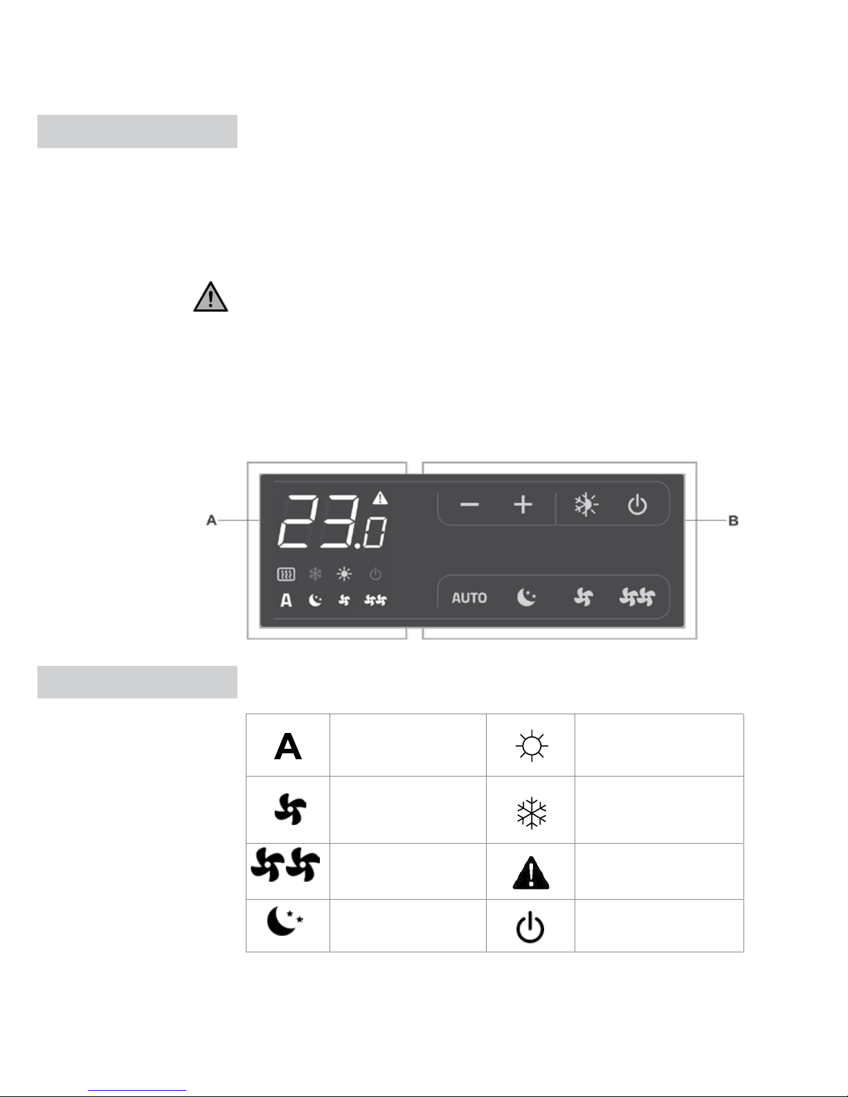
Die Steuerung ermöglicht über die im linken Bedienfeldbereich
befindlichen Folien-Tasten mit Hintergrundbeleuchtung einen Zugriff auf die
Temperatursteuerung und die Programme NACHTBETERIEB, MIN-LÜFTER
und MAX-STEUERUNG eine unterschiedlichen Funktionen: vollständig
autonome Regelung der Raumtemperatur. Es verfügt über eine OffsetMöglichkeit und eine Frostschutzfunktion, die selbst im Standby-Betrieb aktiv
ist. Das Steuergerät besitzt einen Speicher, wodurch die Einstellungen bei
ausgeschaltetem Gerät oder Stromausfall nicht verloren gehen.
Das Gerät reduziert für einen erhöhten Nachtkomfort 20 s nach dem letzten
Bedienvorgang die Helligkeit und zeigt danach die Raumtemperatur an.
Beliebige Taste drücken, um zur max. Helligkeit zurückzukehren.
Der im Gerät befindliche Wassertemperatursensor (10 kΩ) erfasst die für den
Heiz- bzw. Kühlbetrieb erforderliche Mindest- bzw. Maximaltemperatur (28 °C
bzw. 20 °C).
Folgende 8 Symbole geben die einzelnen Zustände und Alarme wieder:
Automatikbetrieb Heizbetrieb EIN
Min. Lüfterdrehzahl Kuhlbetrieb EIN
Max. Lüfterdrehzahl
Alarmanzeige
(leuchtet dauerhaft)
Nachtbetrieb Betriebsanzeige
1 ALLGEMEINE ANGABEN
BEDIENFELD
SYMBOLE
03 BEDIENFELD / DISPLAY
A Temperaturanzeige
B Folienfasten
Page 31
NL
FR
DE
EN
IT
PL
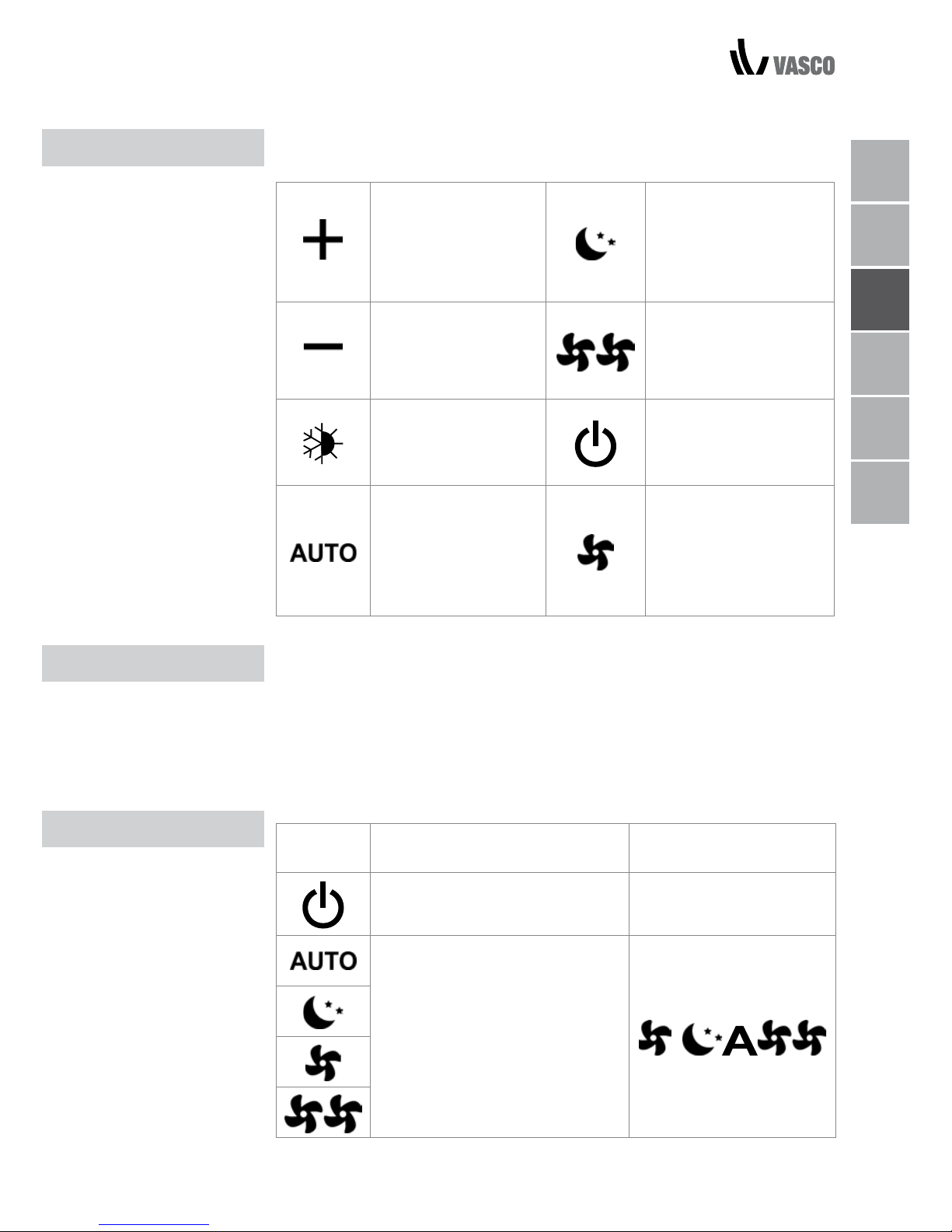
8 Tasten mit Hintergrundbeleuchtung bieten Zugriff auf die
unterschiedlichen Funktionen:
Temp +
Erhöhung der
Solltemperatur
Nachtbetrieb:
Reduzierung der
Lüfterdrehzahl auf ein
bestimmtes Niveau bei
automatischer
Temp –
Reduzierung der
Solltemperatur
Betrieb bei max. Lüfterdrehzahl: Für einen
Gerätebetrieb bei
maximaler Lüfterdrehzahl.
Heizen / Kühlen: Um
zwischen den Betriebsarten Heizen und
Kühlen zu wechseln
AN / Standby: Um das
Gerät anzuschalten bzw.
in den Standby-Betrieb
zu versetzen.
Regelt die
Lüfterdrehzahl
vollautomatisch
zwischen einem
Mindest- und
Maximalwert
Betrieb bei min.
Lüfterdrehzahl:
Für einen Gerätebetrieb
bei minimales
Lüfterdrehzahl
Das Gerät muss für eine Bedienung über das Bedienfeld am Netz
angeschlossen sein. Erfolgt der elektrische Anschluss über einen
Hauptschalter, dann muss auch dieser eingeschaltet werden.
- Gerät über den Hauptschalter einschalten
Gerätebetrieb aktivieren
Taste Vorgang Display
Einschalttaste
(Standby-Betrieb) betätigen
EIN-Symbol leuchtet
Eine der vier Betriebsarten durch
Drücken der entsprechenden
Taste auswählen.
TASTENFUNKTIONEN
GERÄTEBETRIEB
GERÄT AKTIVIEREN
TASTENFUNKTIONEN / GERÄTEBETRIEB / GERÄT AKTIVIEREN 04
Page 32
05 BETRIEBSARTEN HEIZEN / KÜHLEN / STANDBY-BETRIEB / TEMPERATURAUSWAHL
HEIZEN /
KLIMATISIEREN
BETRIEBSART
EINSTELLEN
STANDBY-BETRIEB
BETRIEB BEI MIN.
LÜFTERDREHZAHL
NACHTBETRIEB
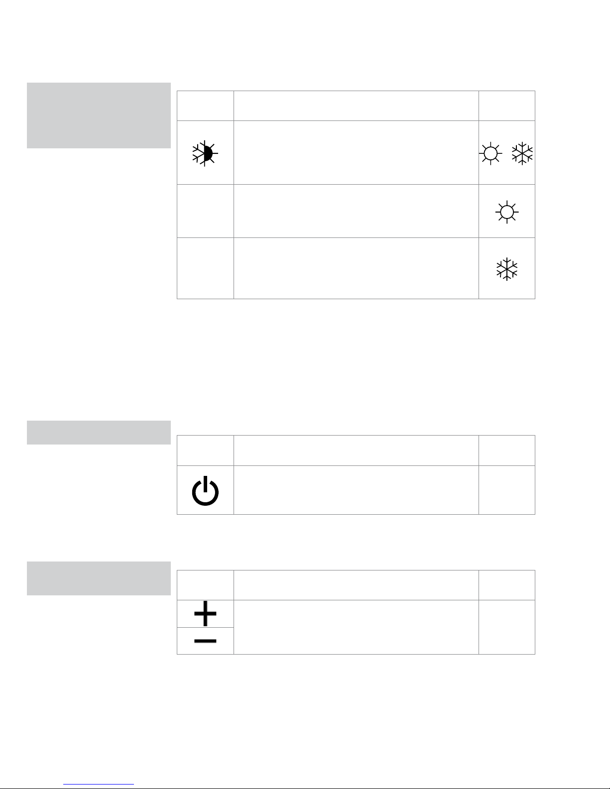
Taste Vorgang Display
Taste für Heiz-/Kühlbetrieb ca. 2 s lang drücken, um
zwischen den Betriebsarten Heizen / Klimatisieren
zu wechseln, was durch die beiden entsprechenden
Symbole angezeigt wird.
Das Symbol erscheint während des Heizbetriebs bei
im Vergleich zur Raumtemperatur höheren Sollwert.
Ist der Sollwert niedriger, sind beide Symbole
deaktiviert.
Das Symbol erscheint während des Kühlbetriebs
bei im Vergleich zur Raumtemperatur niedrigeren
Sollwert. Ist der Sollwert höher, sind beide Symbole
deaktiviert
Wenn eines der beiden Symbole blinkt, ist die (warme bzw. kalte)
Wassertemperatur nicht ausreichend und der Lüfter stoppt, bis diese eine
für die gewünschte Raumtemperatur ausreichende Temperatur erreicht
hat. Erhält das Gerät nach dem Einschalten das entsprechende Signal
von Wassertemperatursensor, dann startet das Gerät im Normalzustand
unter Berücksichtigung der Mindest- und maximalen Schwellenwerte. Das
Gerät erfasst außerdem über eine Funktion die Abwesenheit den Ausfall
Wassertemperatursensors. In dem Fall werden die Schwellenwerte für einen
Lüfterhalt ignoriert.
Taste Vorgang Display
Die EIN-/Standby-Taste ca. 2 s drücken. Bei einem
Display ohne Signalanzeige befindet sich das
System im Standby-Betrieb.
Aus
In dieser Betriebsart ist die Frostschutzfunktion sichergestellt. Sinkt die
Raumtemperatur auf unter 5 °C, dann werden die Magnetventile des
Heizungskreislaufs geöffnet.
Taste Vorgang Display
Mit den beiden Erhöhen-/Reduzieren-Tasten
die gewünschte Raumtemperatur über die
3-Ziffernanzeige einstellen.
20.5
Der Einstellbereich liegt zwischen 16 °C und 28 °C, mit Einstell-Stufen zu je
0,5 °C, wobei auch Werte außerhalb des erlaubten Bereiches (ab 5 °C bis
40°C) zulässig sind (außer im Automatikbetrieb). Diese Ausnahmewerte jedoch
nur kurzfristig einstellen und dann durch einen Zwischenwert ersetzen.
Der Regler besitzt ein sehr präzises Regelverhalten: Sollwert einstellen und
abwarten, bis sich der Regler anhand der erfassten Ist-Temperatur des Raums
eingeregelt hat.
TEMPERATUR-
AUSWAHL
Page 33
NL
FR
DE
EN
IT
PL
BETRIEBSARTEN 06
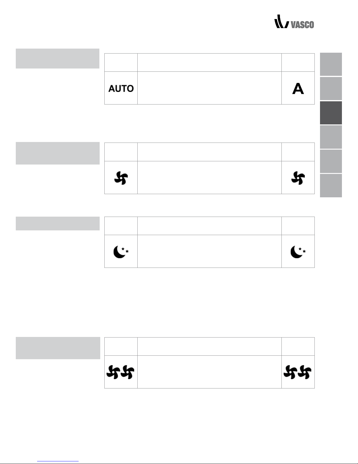
AUTOMATIC
OPERATION
BETRIEB BEI MIN.
LÜFTERDREHZAHL
NACHTBETRIEB
BETRIEB BEI MAX.
LÜFTERDREHZAHL
Taste Vorgang Display
Taste AUTO drücken und gedrückt halten Die
aktivierte Funktion wird im Display über das
entsprechende Symbol angezeigt.
Die Lüfterdrehzahl wird je nach Differenz der Ist-Raumtemperatur zum Sollwert
automatisch zwischen dem Mindest- und Maximalwert mit Hilfe eines
PI-Regelalgorithmus geregelt.
Taste Vorgang Display
Taste für Flüsterbetrieb drücken und gedrückt
halten. Die aktivierte Funktion wird im Display über
das entsprechende Symbol angezeigt.
Die Lüfterdrehzahl wird auf einen voreingestellten Minimalwert begrenzt.
Taste Vorgang Display
Taste für Nachtbetrieb drücken und gedrückt
halten. Die aktivierte Funktion wird im Display über
das entsprechende Symbol angezeigt.
In dieser Betriebsart wird die Lüfterdrehzahl auf ein sehr niedrigen Wert
herunterfahren und die Solltemperatur dabei wie folgt geregelt:
- Rückgang der Temperatur um 1 °C nach 1 Std. und um 1 weiteres Grad
nach 2 Stunden im Heizbetrieb.
- Im Kühlbetrieb: Anstieg der Temperatur um 1 °C nach 1 Std. und
um 1 weiteres Grad nach 2 Stunden;
Taste Vorgang Display
Taste für max. Lüfterdrehzahl drücken und gedrückt
halten. Die aktivierte Funktion wird im Display über
das entsprechende Symbol angezeigt.
In dieser Betriebsart wird im Heiz- oder Kühlbetrieb die maximal mögliche
Lüfterstufe aktiviert. Sobald die gewünschte Raumtemperatur erreicht ist,
empfehlen wir für einen höheren Komfort und leiseren Betrieb, auf eine der
drei anderen Betriebsarten umzuschalten.
Page 34
07 GERÄTEBETRIEB DEAKTIVIEREN / TEMPERATUROFFSET
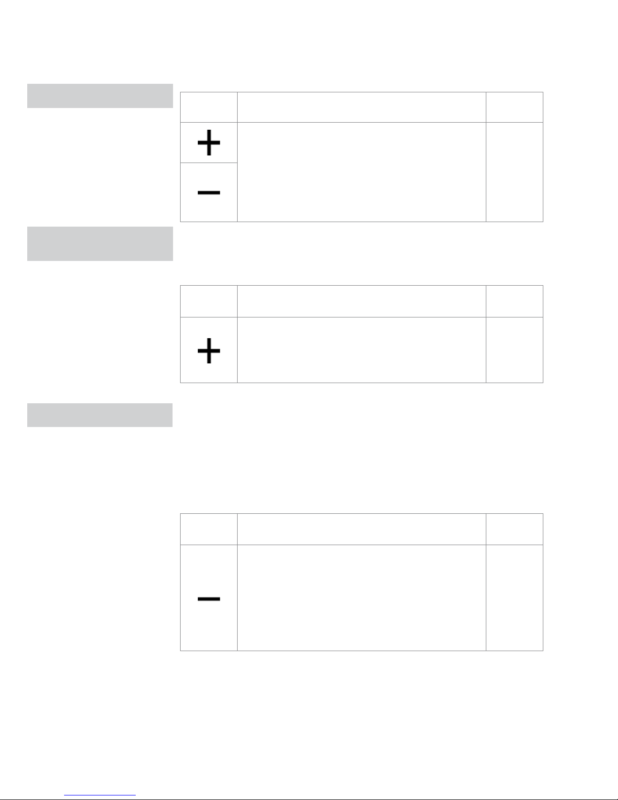
TASTENSPERRE
GERÄT LÄNGERFRISTIG
Taste Vorgang Display
Für eine Tastensperre 3 Sekunden lang gleichzeitig
die Tasten „+“ und „–“ drücken. Das Display zeigt
anschließend „bL“ an. Der Bediener kann keine
Aktionen ausführen. Beim Drücken einer beliebigen
Taste erscheint die Meldung „LOC“. Um die
Tastensperre aufzuheben, den gleichen Vorgang
wiederholen.
bL
Das Gerät reduziert für einen erhöhten Nachtkomfort 20 s nach dem letzten
Bedienvorgang die Helligkeit und zeigt danach die Raumtemperatur an. Ist die
Anzeige immer noch zu hell, kann das Display komplett ausgeschaltet werden.
Taste Vorgang Display
Bei ausgeschaltetem Display 5 s lang die Taste „+“
drücken, bis „01“ erscheint. Mit Taste „–“ den Wert
00 einstellen und 20 s warten, um zu überprüfen,
ob die Einstellung übernommen wurde.
00
Da der Temperatursensor sich an der Geräteunterseite befindet, kann die
erfasste Temperatur unter Umständen von der tatsächlichen Raumtemperatur
abweichen. Mit dieser Funktion lässt sich der angezeigte Wert in einem
Bereich von –9 / + 12 K in Intervallen von 0,1 °C abgleichen. Diesen Abgleich
jedoch mit Sorgfalt ausführen und nur dann, wenn mit einem zuverlässigen
Messgerät eine tatsächliche Differenz zur tatsächlichen Raumtemperatur
ermittelt wurde!
Taste Vorgang Display
Bei abgeschaltetem Display die (-)-Taste 5 s lang
gedrückt halten, um das Einstellmenü für den Offset
des AIR-Temperatursensors aufzurufen. Offset mit
den Tasten (+) und (–) in einem Bereich zwischen
-9 K und +12 K in Schritten van 0,1 K einstellen.
20 s nach der letzten Eingabe schaltet sich das
Display ab und der Einstellwert wird gespeichert.
00.0
DISPLAY-HELLIGKEIT
REDUZIEREN
TEMPERATUROFFSET
Page 35
NL
FR
DE
EN
IT
PL
GERÄT LÄNGERFRISTIG ABSCHALTEN / STÖRUNGSMELDUNGEN 08
GERÄT LÄNGERFRISTIG
ABSCHALTEN
STÖRUNGS-
MELDUNGEN
Zum Abschalten des Geräts für einen längeren Zeitraum (z. B. im Urlaub) wie
folgt verfahren:
- Gerät über die Einschalttaste ausschalten
- Netzschalter ausschalten.
Die Frostschutzfunktion ist nicht mehr aktiv.
Störung Display
Raumtemperatursensor ist defekt.
E1
Störung des Lüftermotors (z. B. Blockierung durch
Fremdkörper, fehlerhafter Drehzahlsensor).
E2
Störung des Wassertemperatursensors (2-RohrAusführung; H2). Sicherstellen, dass es sich um einen
10-kΩ-Sensor handelt.
E3
Mikroschalter S1 (Filterrost) hat infolge eines
Filterreinigungsalarms ausgelöst.
Gr
Page 36
09 AUSSENREINIGUNG / LUFTANSAUGFILTER REINIGEN
AUSSEN-
REINIGUNG
Gerät vor sämtlichen Reinigungs- und Wartungsarbeiten über den
Hauptschalter vom Netz trennen.
Gerät abkühlen lassen, streichen.
Keine scheuernden Schwämme oder abschleifende bzw. scheuernde
Reinigungsprodukte verwenden, um keine lackierten Flächen zu beschädigen.
Bei Bedarf die Außenflächen des Gebläsekonvektors mit einem weichen,
feuchten Tuch reinigen.
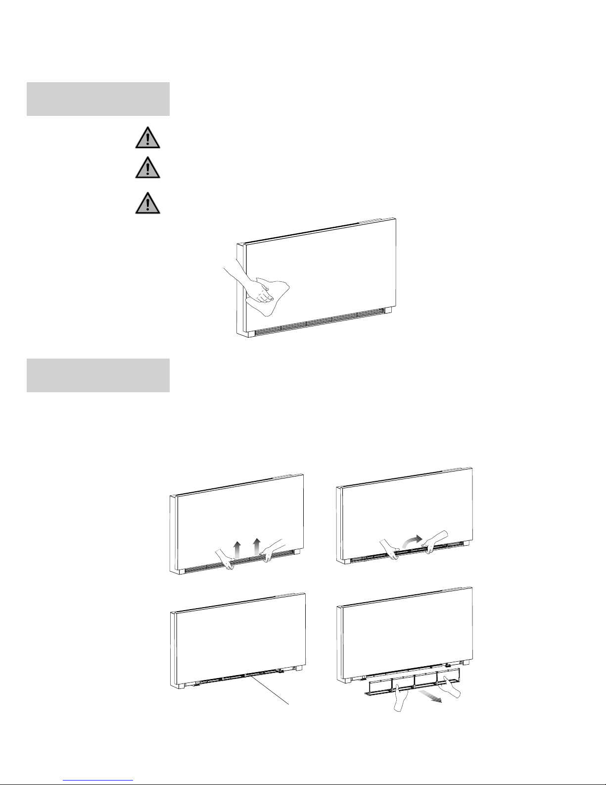
Luftfilter wie folgt nach längerem Gebrauch und gemäß der
Schwebstoffkonzentration in der Luft reinigen bzw. wenn das Gerät nach
längerer Außerbetriebnahme wieder eingesetzt werden soll.
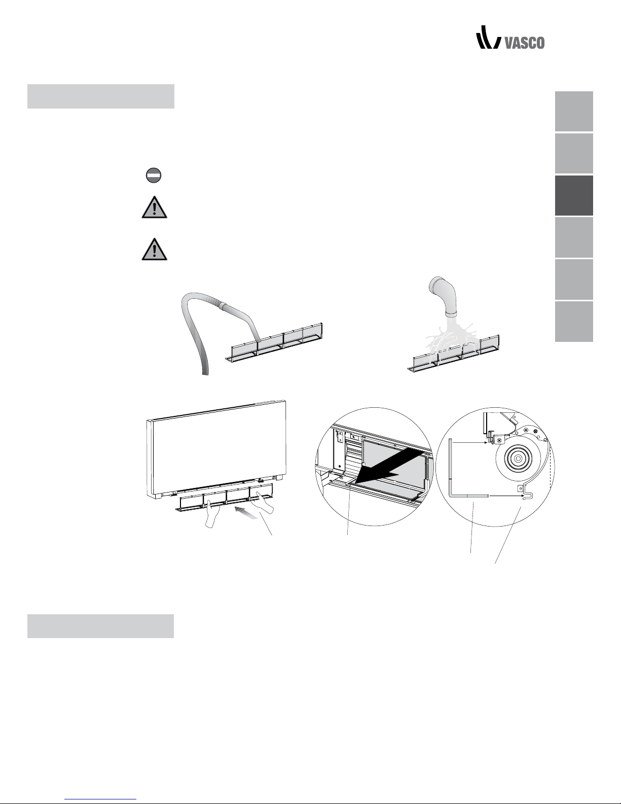
FILTERZELLEN ENTFERNEN
- Zum Entfernen den Filter horizontal nach außen ziehen.
2 WARTUNG
LUFTANSAUGFILTER
REINIGEN
filter extraction
A
B
C
D
Page 37
NL
FR
DE
EN
IT
PL
FILTERREINIGUNG / ENERGIESPARTIPPS 10
A Filter
B Unterkante
C Filtergehäuse
- Filter mit einem Staubsauger absaugen
- Bei starkes Verschmutzung Filter unter fließendem Wasser ohne
Reinigungs- oder Lösungsmittel reinigen und trocknen lassen.
- Beim Austauschen des Gebläsekonvektorfilters besonders darauf achten,
die kurze Unterkante (B) in das Gehäuse (C) einzusetzen.
Niemals das Gerät ohne Siebfilter benutzen.
Das Gerät ist mit einem Sicherheitsschalter ausgestattet, der einen Gerätebetrieb
ohne das Lüfterrost ausschließt.
Nach der Filterreinigung überprüfen, ob das Lüfterrost wieder ordnungsgemäß
eingebaut ist.
FILTERREINIGUNG
- Sicherstellen, dass die Filter immer sauber sind;
- Türen und Fenster in den zu klimatisierenden Räumen weitestgehend
geschlossen halten
- Im Sommer die zu kühlenden Räume weitestgehend vor direktem
Sonnenlicht schützen (mit Vorhängen, Jalousien etc.)
ENERGIESPARTIPPS
A
B
B
C
Page 38

3 STÖRUNGSBEHEBUNG
STÖRUNGSBEHEBUNG Bei Undichtigkeiten oder ungewöhnlichem Betriebsverhalten sofort das Gerät
von der Strom- und Wasserversorgung trennen.
Bei einer der folgenden Erscheinungen ein autorisiertes Kundenzentrum oder
qualifizierte Techniker benachrichtigen, jedoch selbst keine Reparaturversuche
ausführen.
- Lüfter startet nicht, selbst wenn sich heißes oder kaltes Wasser im
hydraulischen Kreis befindet.
- Im Heizbetrieb tritt Wasser aus dem Gerät aus.
- Nur im Kühlbetrieb tritt Wasser aus dem Gerät aus.
- Gerät verursacht ungewöhnliche Geräusche.
- Rostbildung an der Frontplatte.
11 STÖRUNGSBEHEBUNG
STÖRUNGSTABELLE
Page 39
NL
FR
DE
EN
IT
PL
TABELLE ZUR STÖRUNGSBEHEBUNG 12
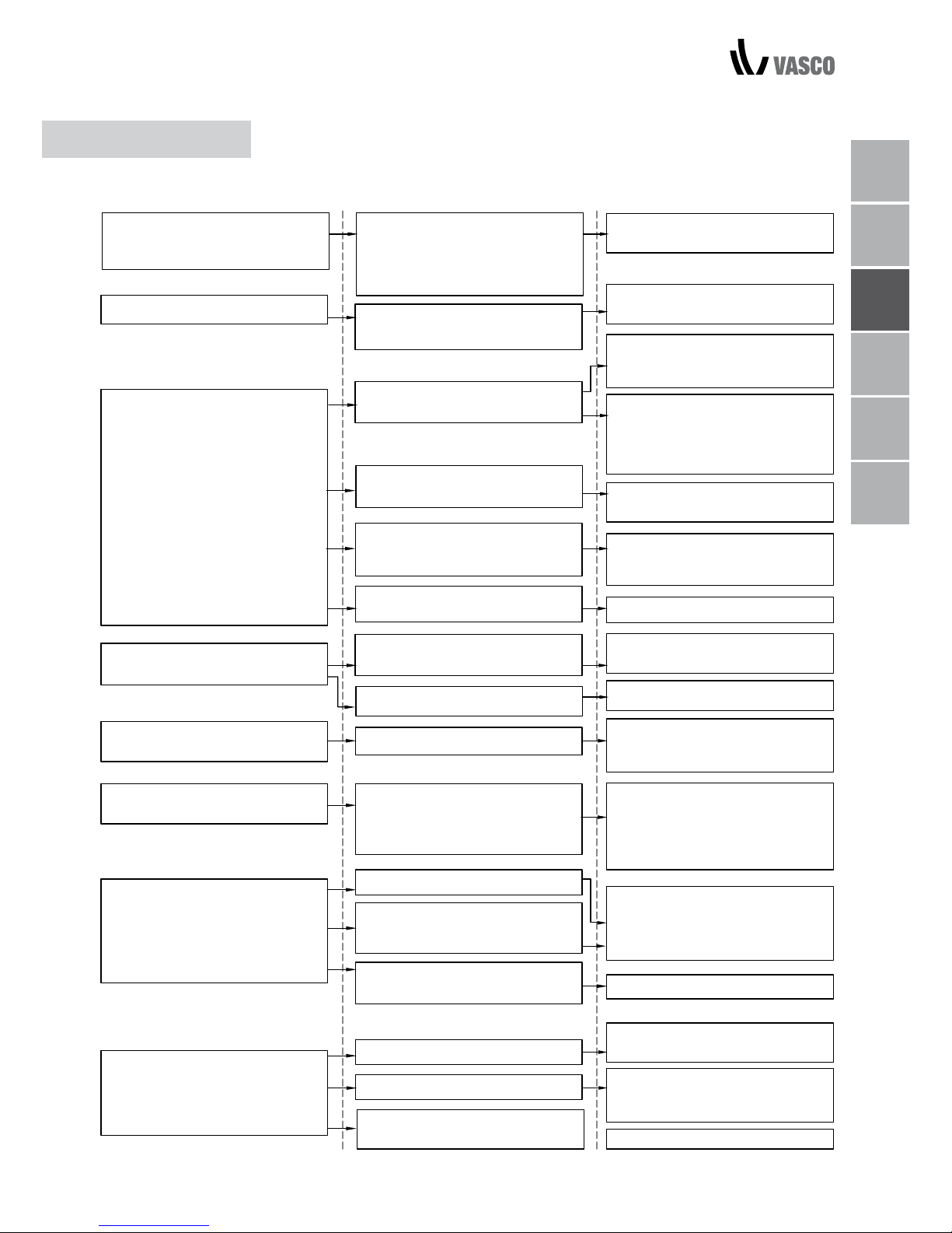
STÖRUNG URSACHE ABHILFE
Das Kreislaufventil benötigt zum
Öffnen etwas Zeit, wodurch das
heiße oder kalte Wasser mehr
Zeit benötigt, um im Gerät zu
zirkulieren
2 bis 3 Minuten warten, ehe das
Kreislaufventil geöffnet wird.
Lüfter reagiert nur verzögert auf
die neuen Temperatur- bzw.
Einstellungsanforderungen.
STÖRUNGSTABELLE
Kein heißes oder kaltes Wasser im
System.
Das Hydraulikventil bleibt
geschlossen.
Heiz oder Kühlsystem auf korrekte Funktion überprüfen.
Ventilgehäuse ausbauen und
überprüfen, ob das Wasser
erneut zu zirkulieren beginnt.
Gerät startet nicht die Lüftung.
Lüfter startet nicht, selbst wenn
sich heißes oder kaltes Wasser im
hydraulischen Kreis befindet..
Funktion des Ventils überprüfen,
indem es separat mit 230 V~ angesteuert wird. Bei korrekter Funktion
kann die elektronische Steuerung
defekt sein.
Lüftermotor ist blockiert oder
defekt.
Motorwicklungen und Drehbar-
keit des Lüfters überprüfen.
Der Mikroschalter für die Lüfterabschaltung bei geöffnetem Filterrost
schließt nicht korrekt.
Zum Überprüfen den Rost
bei aktiviertem Mikroschalter
schließen.
Die elektrischen Anschlüsse sind
fehlerhaft.
Elektrische Anschlüsse überprüfen.
Leckstellen in den hydraulischen
Anschlüssen des Systems.
Leckstelle überprüfen und
abdichten.
Während des Heizbetriebs tritt
Wasser aus dem Gerät aus.
Leckage in der Ventileinheit.
Check the state of the gaskets.
Thermoakustische Isolierung auf
korrekten Sitz überprüfen.
Taubildung auf der Frontblende.
Wärmeisolierung hat sich gelöst.
Phänomen verschwindet, sobald
die Luftfeuchtigkeit wieder zu sinken
beginnt. Bei nur wenigen Wasser
tropfen am Gerät handelt es sich
nicht um Anzeichen einer Störung.
Wassertropfen am
Luftauslassgitter.
Bei hoher Luftfeuchtigkeit
(> 60 %) kann sich Kondensation
bilden, insbesondere bei niedrigen
Lüfterdrehzahlen.
Falls erforderlich, Auffang reinigen und/
oder das Gefälle der Kondensatleitun
-
gen vergrößern.
Nur während des Betriebes bei
aktiverkühlung tritt Wasser aus
dem Gerät aus.
Der Kondensatauffang ist verstopft.
Für eine korrekte Funktion des
Kondensablasses ist kein Gefälle
erforderlich.
Anschlussrohre und Ventileinheit
sind nicht gut genug isoliert.
Isolierung der Rohrleitungen überprüfe
Das Gerät verursacht ungewöhnliche Geräusche.
Lüfter hat Kontakt zur Konstruktion.
Der Lüfter hat ein Umwucht
Filter auf Verstopfung überprüfen
und ggf. reinigen
Freigängigkeit des Lüfters prüfen
ud ggf sicherstellen.
Unwucht im Gerätelüfter
verursacht übermässige Gerätevibrationen: Lüfter austauschen.
Filter reinigen.
Page 40

13 GARANTIEBEDINGUNGEN
4 GARANTIEBEDINGUNGEN
Kruishoefstraat 50, B-3650 Dilsen
T. +32 (0)89 79 04 11
F. +32 (0)89 79 05 00
[email protected]
www.vasco.eu
HERSTELLERERKLÄRUNG
VASCO erklärt hiermit, dass der Gebläsekonvektor über die CE-Kennzeichnung verfügt und in Übereinstimmung mit folgenden EU-Richtlinien entworfen,
gefertigt und kommerzialisiert wurde:
Richtlinie 2014/35/EU (Niederspannungsrichtlinie), einschließlich folgender
technischer Normen:
EN 60335-2-40:2003 + A11:2004 + A12:2005 + A1:2006 + EC:2006
+ A2:2009 + A13:2012 + A13/EC:2013, EN 60335-1:2002 + A11:2004
+ A1:2004 + A12:2006 + A2:2006+ A1/EC:2007 + A13:2008 + EC:2009
+ EC:2010 + A14:2010 + A15:2011
Richtlinie 2014/30/EU (EMV-Richtlinie), einschließlich folgender technischer Normen:
EN 60335-1:2012, EN 55014-1:2006 + A1:2009 + A2:2011,
EN 61000-3-2:2006 + A1:2009 + A2:2009, EN 61000- 3-3:2013,
EN 55014-2:1997 + A1:2001 + A2:2008
RoHS-Richtlinie 2011/65/EU
Vasco Group nv
Dilsen, Belgien, August 2017
P. Nijs, CEO
VASCO gewährt für den Niva Gebläsekonvektor eine Garantie von zwei Jahren ab
Kaufdatum. Als Nachweis für das Kaufdatum gilt das Rechnungsdatum der Installationsfirma. Steht keine Rechnung zur Verfügung, dann entspricht das Herstelldatum
dem Rechnungsdatum. Die Garantie umfasst lediglich einen Austausch von Komponenten, des Lüfters und der Schaltungsplatine. Reparaturen führen nicht zu einer
Verlängerung des Garantiezeitraums für Ersatzteile. Von der Garantie ausgeschlossen
sind:
• Kosten für Zusammenbau und Zerlegung
• Mängel, die auf unsachgemäße Handhabung,
Fahrlässigkeit oder Beschädigung zurückzuführen sind
• Mängel, die auf Handhabung oder Reparaturen Dritter ohne unsere
Zustimmung zurückzuführen sind
• Mängel, die auf den Gebrauch des Geräts in einer ungeeigneten Umgebung
zurückzuführen sind
• Streichen. Ein Betrieb des Gebläsekonvektors unter oben aufgeführten
Bedingungen führt zum Garantieverlust. Vor einen Rückversand von defekten
Baugruppen muss sich der Installationsbetrieb zuerst an VASCO
wenden. Der Installationsbetrieb erhält anschließend von VASCO eine
Garantierücksendenummer. Die an VASCO zurückgesandten Komponenten
müssen diese Garantierücksendenummer enthalten.
Page 41

NL
FR
DE
EN
IT
PL
CONTENTS 01
CONTENTS
1 GENERAL
Electronic panel 2
Display 2
Key function 3
General On Switch 3
Activation 3
Heating/cooling operation modes setting 4
Stand-by 4
Temperature selection 4
Automatic operation 5
Silent operation 5
Night-time operation 5
Operation at maximum ventilation speed 5
Key Lock 6
Reduce brightness to minimum 6
Deactivation 6
Room temperature probe regulation offset 6
Switching off for long periods 7
Error signals 7
2 MAINTENANCE
External cleaning 8
Air suction lter cleaning 8
Cleaning the lters 9
Suggestions for power saving 9
3 TROUBLESHOOTING
Troubleshooting 10
Troubleshooting table 11
4 WARRANTY CONDITIONS
Warranty conditions 12
Page 42
02 CONFORMITY / SYMBOLS / CONTENTS
This unit complies with European directives:
• Low voltage 2014/35/EU
• Electro-magnetic compatibility 2014/30/EU
The pictograms in the next chapter provide the necessary information for
correct, safe use of the machine in a rapid, unmistakable way.
SAFETY PICTOGRAMS
Generic danger
Signals to the personnel that the operation described could cause
physical injury if not performed according to the safety rules.
Danger of high voltage
Signals to the personnel that the operation described could cause
electrocution if not performed according to the safety rules.
Danger due to heat
Signals to the personnel that the operation described could cause burns
if not performed according to the safety rules.
Prohibition
Refers to prohibited actions.
CONFORMITY
SYMBOLS
Page 43
NL
FR
DE
EN
IT
PL
These controls make room temperature adjustment (with offset settable from
the keyboard) completely autonomous through the AUTO, SILENT, NIGHT and
MAX programmes by means of a probe located in the lower part of the device,
ensuring anti-freeze safety even when set to stand-by.
The control panel has a memory, so settings will not be lost if the appliance is
switched off or in the power supply is cut.
After 20 seconds from the last action the panel brightness will be reduced for
improved night-time comfort, and the room temperature will appear on the
display. Press any key to restore maximum brightness.
The 10 kΩ water temperature probe positioned in the device battery
regulations the minimum level when heating (28°C) and the maximum level
when cooling (20°C).
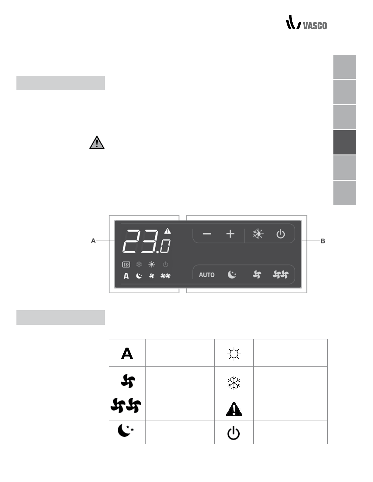
Any statuses and alarms are also shown on the display by using 8 specific
symbols:
Automatic operation Heating on
Silent operation Cooling on
Maximum ventilation
speed
Alarm indicator
(solid light)
Night-time operation Panel off indicator
1 GENERAL
ELECTRONIC PANEL
DISPLAY
A Display
B Keys
NL
FR
DE
EN
IT
PL
ELECTRONIC PANEL / DISPLAY 03
Page 44
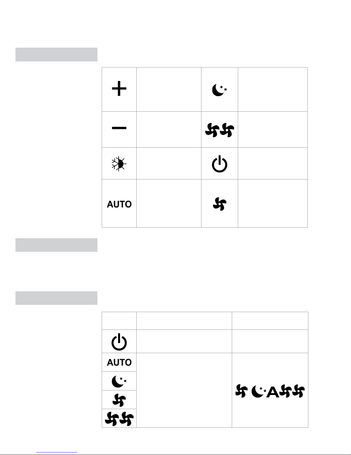
The various functions are set using 8 backlit keys:
Temp +
is for increasing the set
temperature
Night-time operation:
limits ventilation speed
to a contained level and
the set temperature is
adjusted automatically.
Temp is for decreasing the
set temperature
Maximum speed
operation: Allows for
the maximum ventilation
speed to be set
Heating / Cooling: for
changing the operation
mode between heating
and cooling
ON/Stand-By: for
activating the device or
for putting it in stand-by.
Sets the regulation
ventilation speed
between a minimum
and maximum value to
an entirely automatic
mode
Silent: limits ventilation
speed to a more
contained value
In order to manage the device via the control panel, this must be connected to
the mains electricity.
If a general switch is installed on the power line, this must also be switched on.
- Turn the device on by activating the general switch
To activate the device
Key Operation Display
Press the ON Stand-by key From off to on
Select one of the 4 operating
modes by pressing the relative
key.
KEY FUNCTION
GENERAL ON SWITCH
ACTIVATION
04 KEY FUNCTION / GENERAL ON SWITCH / ACTIVATION
Page 45
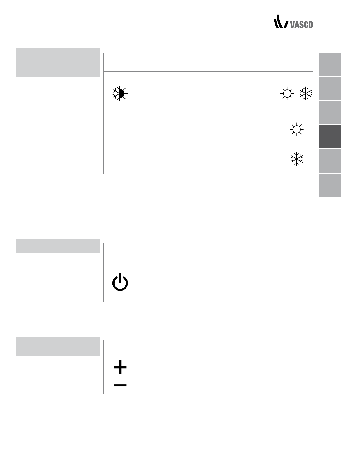
HEATING/COOLING
OPERATION
MODES SETTING
STAND BY
Key Operation Display
Keep the Heating / Cooling key pressed for approx.
2 seconds to change the mode between heating
and cooling, which is indicated by the 2 symbols
that appear if heating or cooling is active.
When heating, the symbol displays when the set
point is higher than ambient temperature, both are
off when the set point is lower.
When cooling, the symbol displays when the set
point is lower than ambient temperature, both are
off when the set point is higher.
One of the two symbols flashing means that the water temperature (hot or
cold) is not sufficient, and stops the fan until the temperature reaches a level
suitable for reaching the required temperature.
If after switching the power on the board detects the H2 probe, start-up
occurs in normal conditions with the minimum and maximum thresholds.
The board also has a function when there is no H2 probe, in such cases the
fan stop thresholds are ignored.
Key Operation Display
Press and hold the ON Stand-By key for approx.
2 seconds. No illuminated signals on the display
at all means that the system is in stand-by (no
operation).
Off
When the control is in this operating mode, anti freezing is in any case
guaranteed. If the ambient temperature drops below 5°C, the solenoid valves
on the hot water output and the boiler are opened.
Key Operation Display
Set the required room temperature using the two
increase/decrease keys to set the temperature
value on the 3-digit display.
20.5
The adjustment range is from 16 to 28°C in intervals of 0.5°C, but out-ofrange values are also accepted, from 5°C to 40°C (unless in auto mode).
Only set these values for brief periods, and then set a intermediate value.
The controller is very precise - set it to the required value and wait for the
controller to regulate itself according to the actual room temperature detected.
TEMPERATURE
SELECTION
NL
FR
DE
EN
IT
PL
HEATING/COOLING OPERATION MODES SETTING / STAND BY / TEMPERATURE SELECTION 05
Page 46
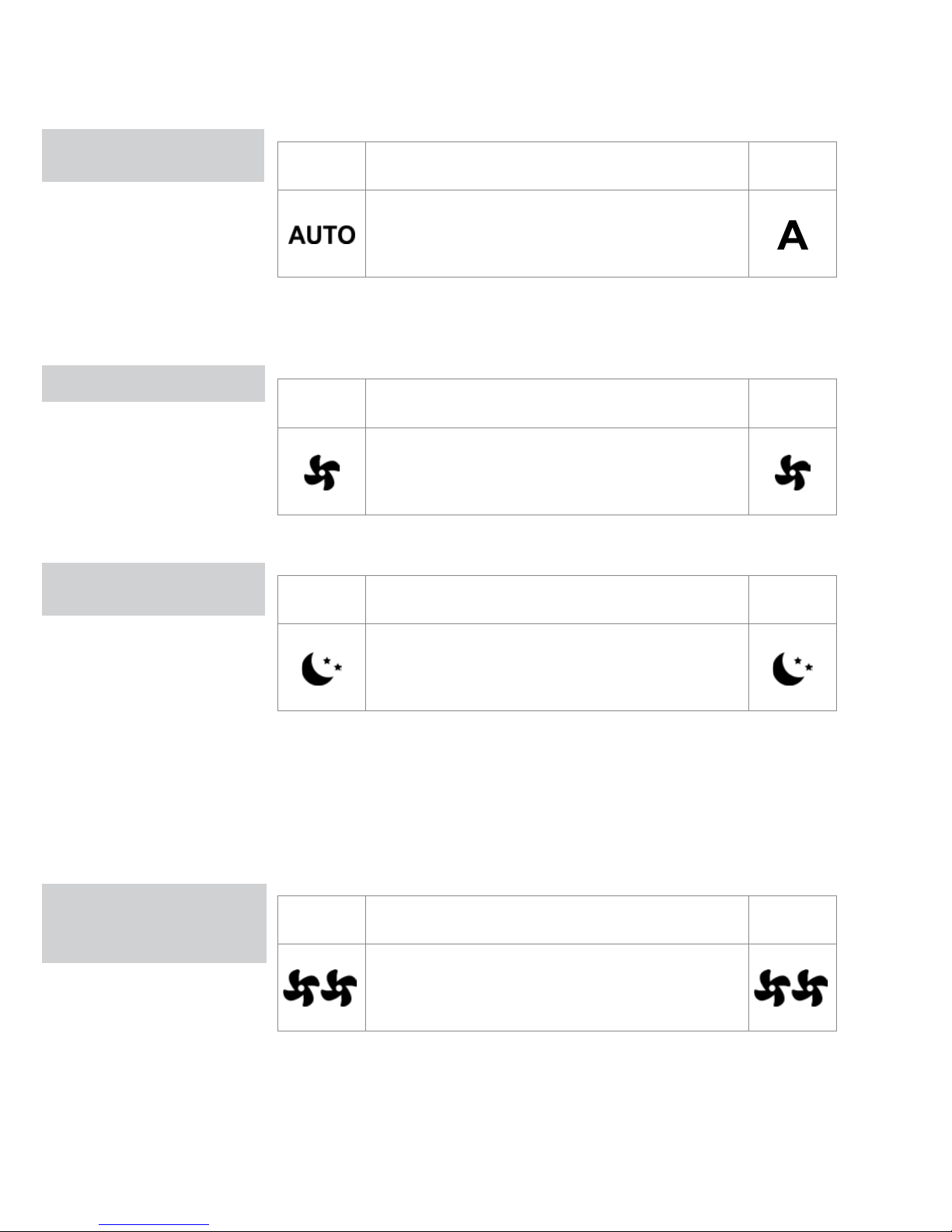
06 AUTOMATIC OPERATION / SILENT OPERATION / NIGHT-TIME OPERATION
AUTOMATIC
OPERATION
SILENT OPERATION
NIGHT-TIME
OPERATION
OPERATION
AT MAXIMUM
VENTILATION SPEED
Key Operation Display
Press and hold the AUTO key. The function being
activated is indicated by the relevant symbol
appearing on the display.
Ventilation speed adjustment is carried out automatically between the
minimum and maximum values, according to the distance of the actual room
temperature from the set point, according to a PI-type algorithm.
Key Operation Display
Press and hold the Silent key. The function being
activated is indicated by the relevant symbol
appearing on the display.
Ventilation speed is limited to a contained maximum value.
Key Operation Display
Press and hold the Night-time operation key. The
function being activated is indicated by the relevant
symbol appearing on the display.
By selecting this mode, ventilation speed is limited to a very contained level
and the set temperature is adjusted automatically, as follows:
- decreases by 1°C after one hour and by another degree after two hours in
heating mode;
- increases by 1°C after one hour and by another degree after two hours in
cooling mode;
Key Operation Display
Press and hold the Max Operation key. The function
being activated is indicated by the relevant symbol
appearing on the display.
In this operation mode, the maximum possible power level is activated
whether heating or cooling.
Once the desired room temperature is reached, we recommend selecting one
of the other 3 operation modes for increased comfort and sound levels.
Page 47
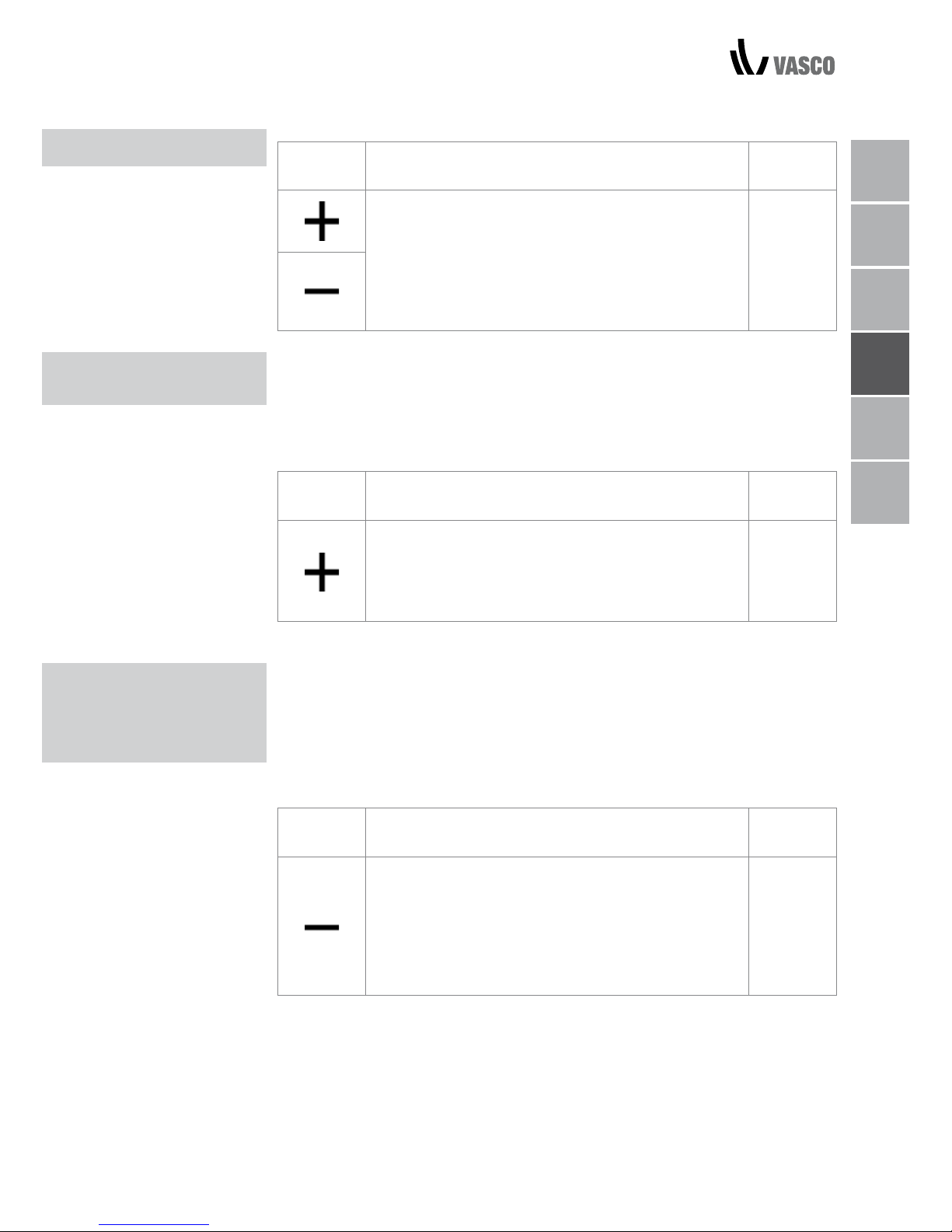
KEY LOCK / REDUCE BRIGHTNESS / DEACTIVATION / ROOM TEMPERATURE REGULATION 07
KEY LOCK
Key Operation Display
By pressing both the + and - keys for 3 seconds, all
keys are locked locally, and this is indicated by "bL"
appearing on the display.
All actions are disabled to the user and whenever
any key is pressed, "LOC" will appear. To unlock
the keys, repeat the sequence.
bL
After 20 seconds from the last action, the panel brightness will be reduced for
improved night-time comfort, and the room temperature will appear on the
display.
If this brightness is still disturbing, the display can be switched off completely.
Key Operation Display
With the display off, press and hold the + key for 5
seconds until "01" is displayed.
Use the - key to change the value to 00 and wait 20
seconds to check the setting has been accepted.
00
As the detection probe is towards the bottom of the device, the temperature
detected may at times differ from the actual room temperature. By using this
function, the value displayed can be adjusted in a range from -9/+12 K in
intervals of 0.1°C. Use this adjustment with care, and only after having actually
detected a discrepancy compared with the actual room temperature using a
reliable device!
Key Operation Display
With the display off, press and hold the - key
for 5 seconds to access the menu which allows
adjustment (using the + and - keys) of the AIR probe
offset displayed, from -9 to +12 K in 0.1 K intervals.
After 20 seconds from the last action, the panel
switches off and the setting is stored.
00.0
REDUCE BRIGHTNESS
TO MINIMUM
ROOM
TEMPERATURE
PROBE
REGULATION OFFSET
NL
FR
DE
EN
IT
PL
Page 48
08 SWITCHING OFF FOR LONG PERIODS / ERROR SIGNALS
SWITCHING OFF FOR
LONG PERIODS
ERROR SIGNALS
When switching off for a season or for holidays, proceed as follows:
- Deactivate the device
- Turn the general unit switch to off.
The antifreeze function is not active.
Error Display
Faulty room temperature (AIR) probe.
E1
Problem with fan motor (e.g. blockage caused by foreign
objects, faulty rotation sensor).
E2
Water temperature probe fault for 2-tube versions (H2).
In this case, ensure that the probe installed is 10 kΩ.
E3
Engaging of grille microswitch S1 due to filter cleaning
operation
Gr
FILTER CLEANING
Page 49
EXTERNAL CLEANING / AIR SUCTION FILTER CLEANING 09
EXTERNAL
CLEANING
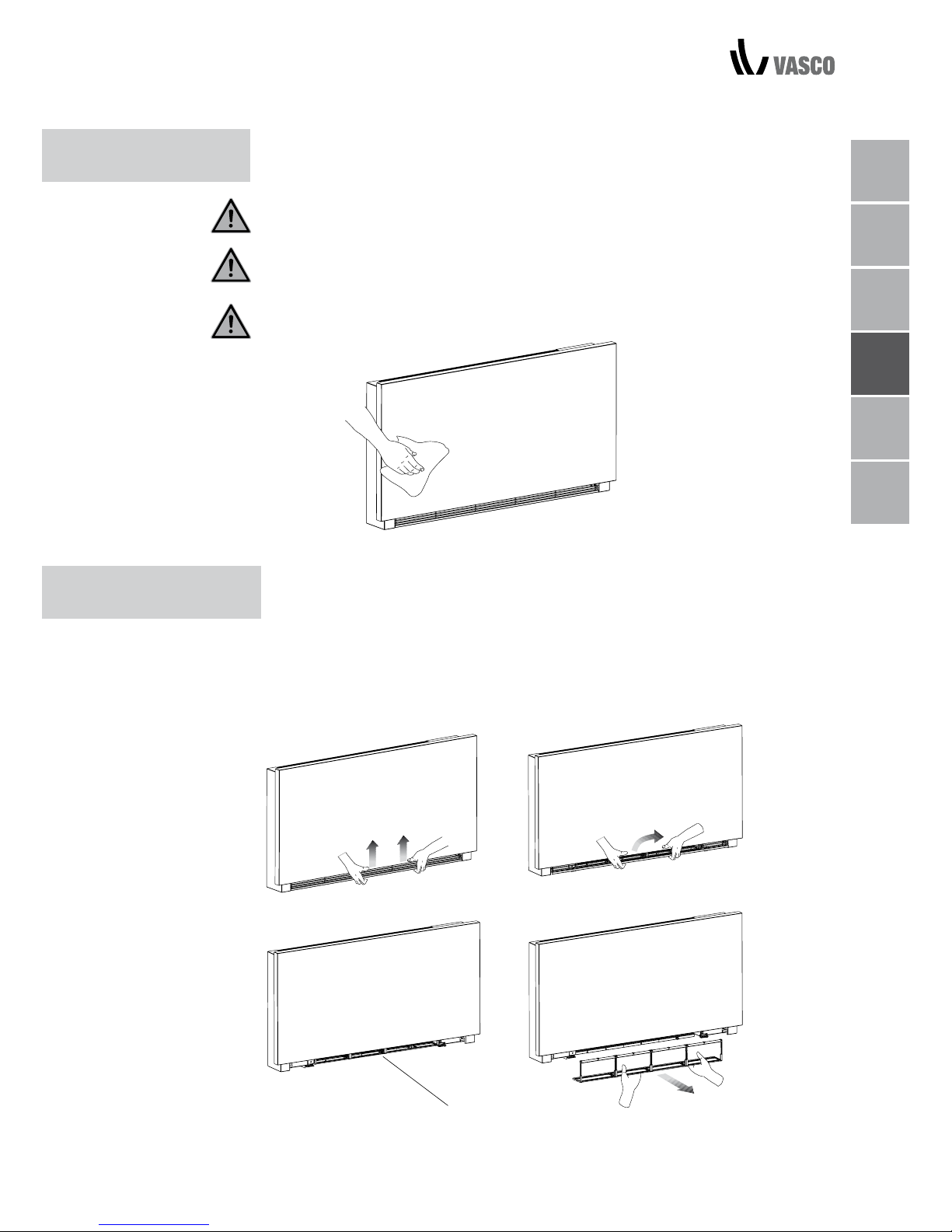
Disconnect the unit from the power supply before each cleaning and
maintenance intervention by setting the main power supply switch to off.
Wait for the components to cool down in order to avoid any burns.
Do not use abrasive sponges or abrasive or corrosive detergents as you might
damage the painted surfaces.
When necessary, clean the external surfaces of the fan coil with a soft damp
cloth.
Clean the air filter after a period of continuous use and according to the
concentration of impurities in the air; or when you wish to start-up the
appliance after a period of inactivity, proceed as described.
REMOVAL OF FILTERING CELLS
- extract the filter by pulling outwards horizontally.
2 MAINTENANCE
AIR SUCTION
FILTER CLEANING
filter extraction
A
B
C
D
NL
FR
DE
EN
IT
PL
Page 50
10 CLEANING THE FILTERS / SUGGESTIONS FOR POWER SAVING
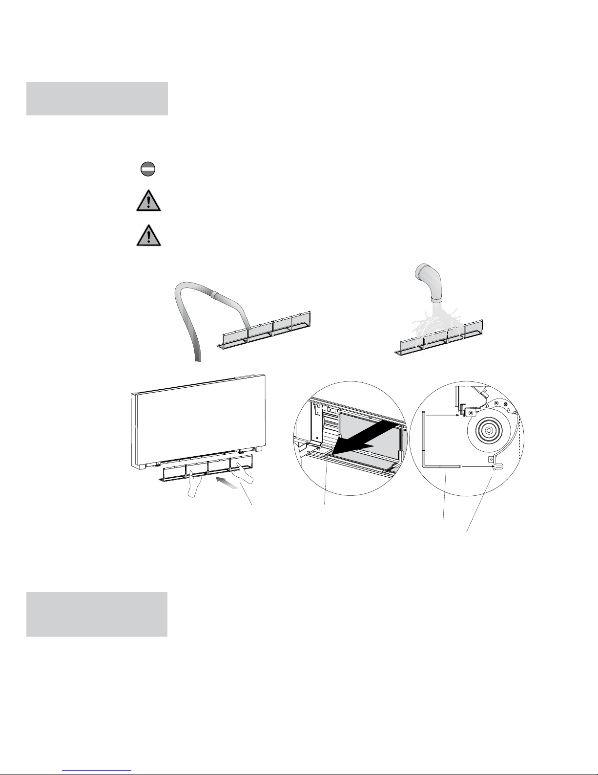
A filter
B lower edge
C filter housing
- Remove dust from the filter with a vacuum cleaner
- Wash the filter under running water without using detergents or solvents,
and leave to dry.
- Replace the filter on the fan coil, paying particular attention to insert the
lower edge in its housing.
Do not use the device without the mesh filter.
The device is fitted with a safety switch that prevents fan operation without the
mobile panel in place.
After filter cleaning, check that the panel is properly mounted.
CLEANING
THE FILTERS
- Ensure filters are constantly clean;
- Keep doors and windows closed as far as possible in rooms to be
conditioned;
- In summer, limit direct sunlight as far as possible in rooms to be conditioned
(with curtains, shutters, etc.).
SUGGESTIONS
FOR POWER SAVING
TROUBLESHOOTING
A
B
B
C
Page 51
3 TROUBLESHOOTING
TROUBLESHOOTING In the event of water leaks or anomalous operation, disconnect mains power
immediately and close all water taps.
If one of the following anomalies should occur, contact an authorised service
centre or qualified personnel, do not try to repair yourself.
- Ventilation does not start even if there is hot or cold water in the hydraulic
circuit.
- The device leaks water when heating.
- The device leaks water only when cooling.
- The device makes excessive noise.
- Rust is forming on the front panel.
NL
FR
DE
EN
IT
PL
TROUBLESHOOTING 11
Page 52
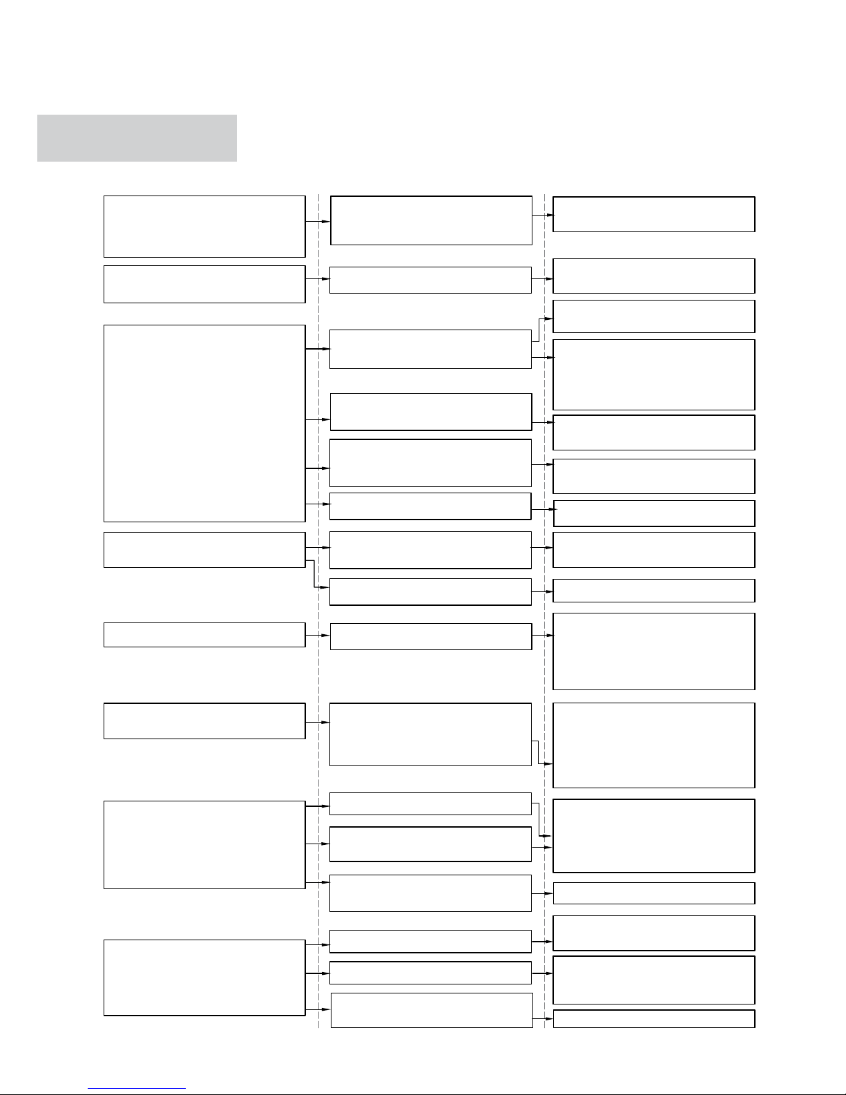
EFFECT CAUSE
The circuit valve needs time to
open and to let cold or hot water
circulate.
Wait 2 or 3 minutes for the circuit
valve to open.
TROUBLESHOOTING
TABLE
No hot or cold water in the system.
The hydraulic valve stays closed.
Check that the boiler or the water
cooler are working.
Disassemble the valve body and
check and restore water circulation.
Ventilation takes a long time to
start when new temperature
settings or anew mode is
activated.
The device doesn’t start
ventilating.
Check that the valve is working by
powering it up separately from a
230V supply. If it starts working, the
problem may be with the electronic
controller.
The fan motor is blocked or
burned out.
Check the motor windings and
that the fan can turn freely.
The microswitch that stops ventilation when opening the filter grill
doesn’t close properly.
Check that closing the grill closes
the contact on the microswitch.
Water leakage from the system
plumbing.
Check for leaks and tighten all
connections.
Leaks from the valve group.
Check the seals
Ventilation does not start even if
there is hot or cold water in the
hydraulic circuit.
Thermal isolators detached.
Check that the thermal sound
isolators are positioned correctly,
paying particular attention to the
one positioned at the front above
the winged battery.
Rust is forming on the front panel.
As soon as relative humidity
decreases, the problem will disappear. In any case, should some
water droplets fall inside the units,
it does not mean that there is a
malfunction.
Water droplets are forming
on the grill and the air outlet.
In situations of high humidity
(>60%) condensation could form,
especially at the minimum
ventilation speeds.
Slowly pour a bottle of water in
the lower part of the battery to
check drainage; if required, clean
the tank and/or improve the
incline of the drain tube.
The device leaks water
only when cooling.
The condensation tank is blocked.
The condensation drain does not
have sufficient incline to drain.
The connection pipes and valve
group are not well isolated.
Check pipe insulation.
The device makes excessive
noise.
The fan touches the structure.
The fan is unbalanced.
Check for dirt in filters and if
necessary, clean them.
Check for dirt in filters and if
necessary, clean them.
An unbalanced fan causes excessive vibrations in the machine:
replace the fan.
Clean the filters.
12 TROUBLESHOOTING TABLE
The device leaks water
when heating.
Electrical connections are incorrect.
Check the electrical connections.
Page 53

WARRANTY CONDITIONS / MANUFACTURER’S DECLARATION 13
NL
FR
DE
EN
IT
PL
4 WARRANTY CONDITIONS
Vasco hereby declares to guarantee the Vasco Niva FC for two years from the date
of purchase. The invoice date of the installation company is proof of the purchase
date. If there is no invoice available, the production date will be the purchase date.
The warranty consists only of replacing spare parts, the fan and electronic printed
board. There is no additional warranty period for spare parts.
The warranty does not entail:
• Assembly and disassembly costs
• Defects, which, in our opinion, are the result of improper handling, negligence
or accidents
• Defects that are the result of handling or repairs by third parties without our
permission
• Defects that are the result of irregular and/or unprofessional maintenance
• Defects that are the result of using the unit in a non-suitable environment
The warranty is void if the FCU is used under the aforementioned conditions. The
installer should contact Vasco for return shipment of defective components. The
installer will receive a warranty return number. The defective components must be
dispatched to Vasco stating this return number.
Kruishoefstraat 50, B-3650 Dilsen
T. +32 (0)89 79 04 11
F. +32 (0)89 79 05 00
[email protected]
www.vasco.eu
MANUFACTURER’S DECLARATION
Vasco declares that the FCU carries the CE label and is designed, manufactured and commercialized in compliance with the following EEC Standards:
LV Directive 2014/35/EU with following technical standards:
EN 60335-2-40:2003 + A11:2004 + A12:2005 + A1:2006 + EC:2006
+ A2:2009 + A13:2012 + A13/EC:2013, EN 60335-1:2002 + A11:2004
+ A1:2004 + A12:2006 + A2:2006+ A1/EC:2007 + A13:2008 + EC:2009
+ EC:2010 + A14:2010 + A15:2011
EMC Directive 2014/30/EU with following technical standards:
EN 60335-1:2012, EN 55014-1:2006 + A1:2009 + A2:2011,
EN 61000-3-2:2006 + A1:2009 + A2:2009, EN 61000- 3-3:2013,
EN 55014-2:1997 + A1:2001 + A2:2008
RoHS Directive 2011/65/EU
Vasco Group nv, Dilsen, België, august 2017
P. Nijs, CEO
Page 54

SOMMARIO
1 GENERALE
Pannello elettronico 2
Display 2
Funzione pulsanti 3
Accensione generale 3
Attivazione 3
Impostazione modalità riscaldamento/raffreddamento 4
Stand-by 4
Impostazione della temperatura 4
Funzionamento automatico 5
Funzionamento silenzioso 5
Funzionamento notturno 5
Funzionamento alla massima velocità di ventilazione 5
Blocco pulsanti 6
Riduzione della luminosità al minimo 6
Disattivazione 6
Regolazione del sensore di temperatura ambiente 6
Spegnimento per lunghi periodi 7
Segnali di errore 7
2 MANUTENZIONE
Pulizia esterna 8
Pulizia del ltro aspirazione aria 8
Pulizia dei ltri 9
Suggerimenti per il risparmio energetico 9
3 RISOLUZIONE DEI PROBLEMI
Risoluzione dei problemi 10
Tabella di risoluzione dei problemi 11
4 CONDIZIONI DI GARANZIA
Condizioni di garanzia 12
Page 55
CONFORMITÀ / SIMBOLI / SOMMARIO 02
NL
FR
DE
EN
IT
PL
Questa unità è conforme alle direttive europee:
• Bassa tensione 2014/35/EU
• Compatibilità elettromagnetica 2014/30/EU
I pittogrammi indicati nel prossimo capitolo forniscono, in modo rapido e
inconfondibile, le informazioni necessarie per l’uso corretto e sicuro
dell’apparecchio
PITTOGRAMMI RELATIVI ALLA SICUREZZA
Pericolo generico
Segnala al personale che l’operazione descritta potrebbe causare lesioni
personali se non eseguita nel rispetto delle norme di sicurezza.
Pericolo di alta tensione
Segnala al personale che l’operazione descritta potrebbe provocare
folgorazione se non eseguita nel rispetto delle norme di sicurezza.
Pericolo di ustioni
Segnala al personale che l’operazione descritta potrebbe provocare ustioni se
non eseguita nel rispetto delle norme di sicurezza.
Divieto
Segnala le operazioni vietate.
CONFORMITÀ
SIMBOLI
Page 56
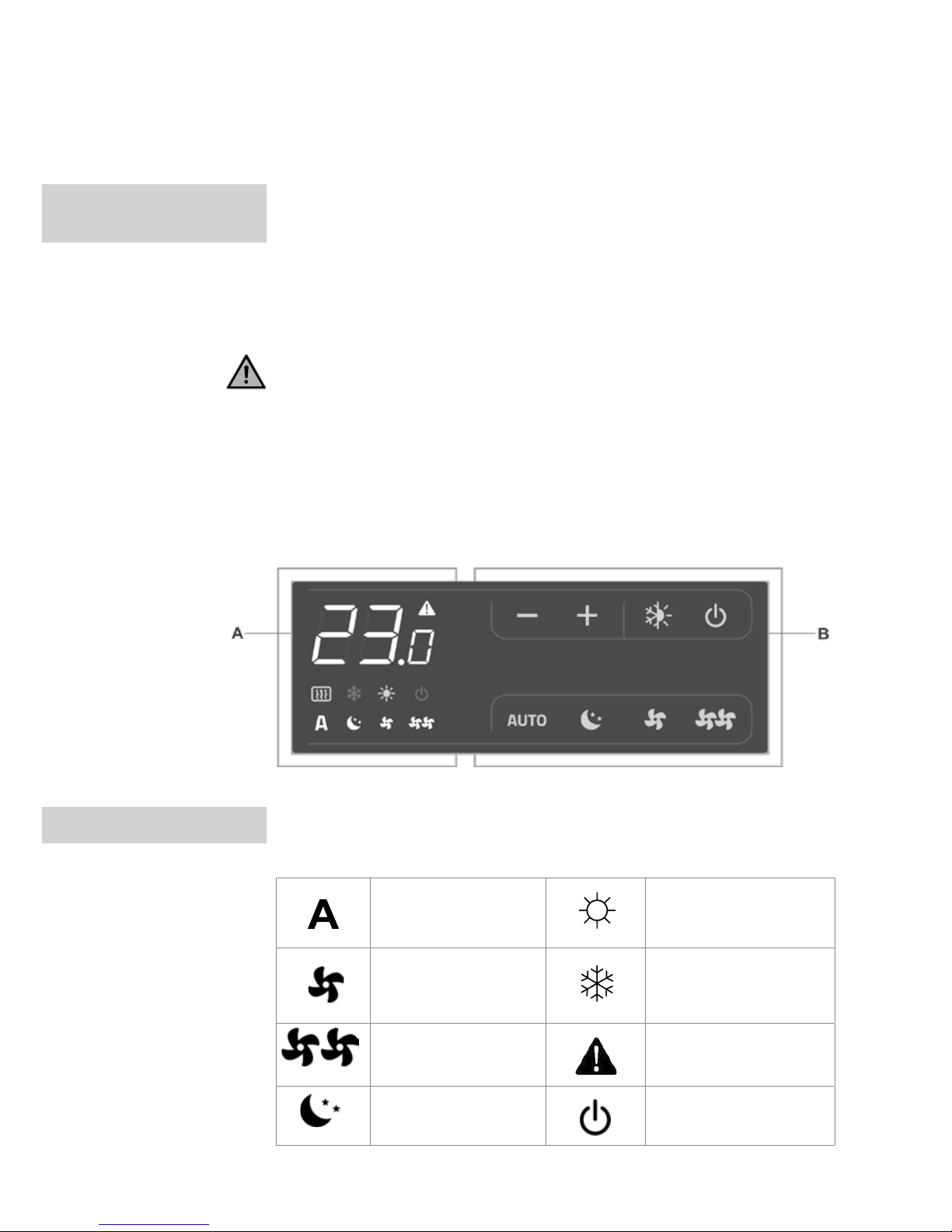
Il comando regola la temperatura ambiente (con offset regolabile
tramite tastiera) completamente in autonomia attraverso le programmazioni
AUTO, SILENZIOSO, NOTTURNO e MAX grazie a un sensore localizzato
nella parte inferiore del dispositivo, garantendo la sicurezza antigelo anche
in modalità stand-by. Le impostazioni rimangono salvate nella memoria
del pannello di controllo anche in caso di spegnimento del dispositivo o
interruzione dell’alimentazione elettrica.
Dopo 20 secondi dall’ultima azione la luminosità del pannello diminuisce per
un migliore comfort durante le ore notturne e sul display viene visualizzata
la temperatura ambiente. Premere un pulsante qualsiasi per ripristinare la
luminosità massima.
Il sensore di temperatura dell’acqua da 10 kΩ situato nella batteria del
dispositivo può gestire il livello minimo in riscaldamento (28 °C) e massimo in
raffreddamento (20 °C).
Qualsiasi stato dell’apparecchio o segnale di allarme viene visualizzato sul
display con 8 simboli specifici
Funzionamento
automatico
Riscaldamento attivo
Funzionamento
silenzioso
Raffreddamento attivo
Massima velocità di
ventilazione
Indicatore di allarme
(spia fissa)
Funzionamento
notturno
Indicazione pannello
spento
1 GENERALE
PANNELLO
ELETTRONICO
DISPLAY
03 PANNELLO ELETTRONICO / DISPLAY
A Display
B Pulsanti
Page 57
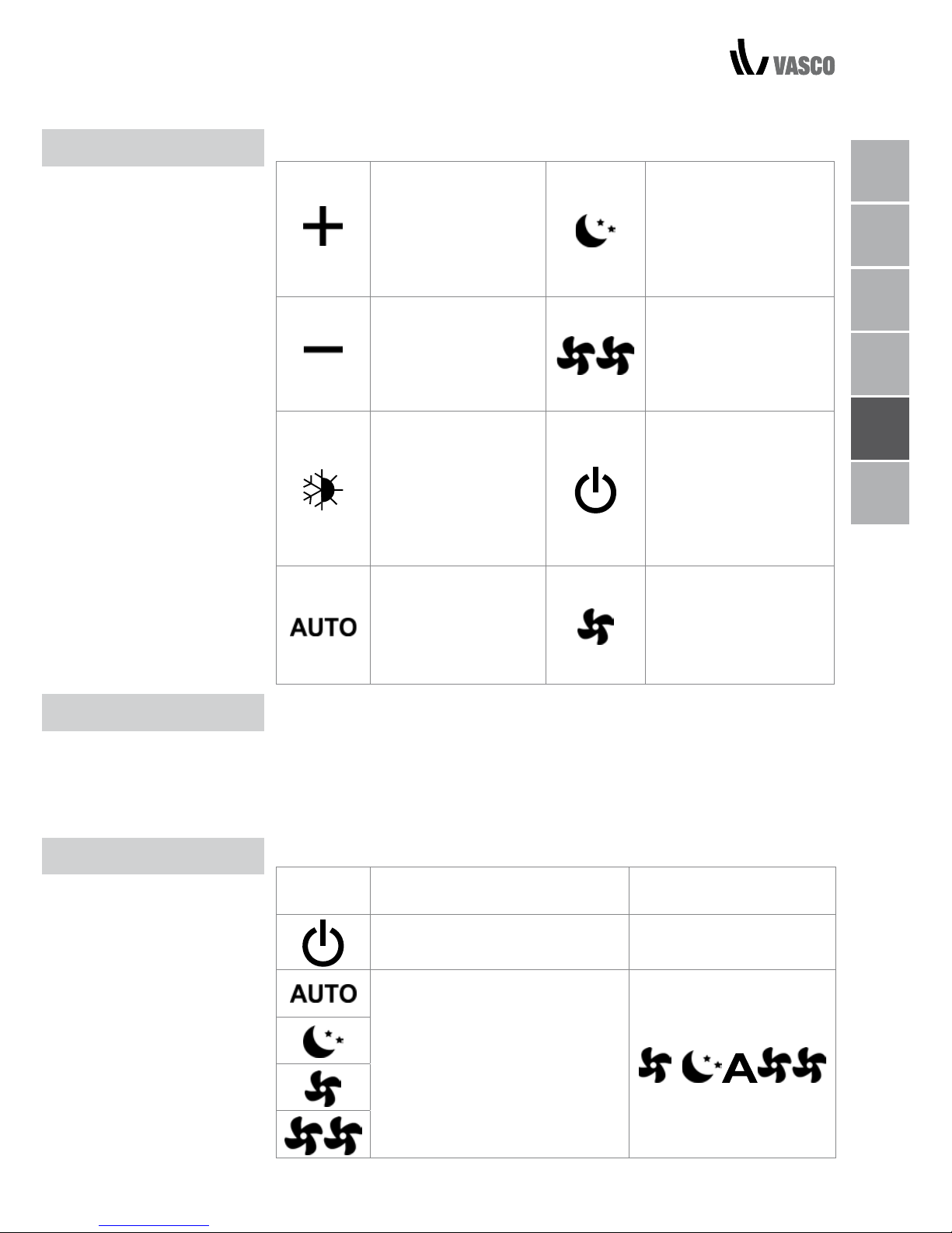
Le diverse funzioni vengono impostate utilizzando 8 pulsanti retroilluminati:
Temp +
consente di aumentare
la temperatura
impostata
Funzionamento notturno:
limita la velocità di ventilazione a un livello
basso e la temperatura
impostata viene regolata
automaticamente.
Temp consente di diminuire
la temperatura
impostata
Funzionamento alla
massima velocità:
consente di impostare
la massima velocità di
ventilazione
Riscaldamento /
raffreddamento:
consente di passare
dalla modalità di
riscaldamento a quella
di raffreddamento e
viceversa
ON/Stand-by: consente
di accendere o
mettere in stand-by
l’apparecchio.
Imposta automaticamente la velocità
di ventilazione tra un
valore minimo e un
valore massimo
Silenzioso: limita la
velocità di ventilazione a
un livello più basso.
Per gestire l’apparecchio tramite il pannello di controllo, questo deve essere
collegato alla rete elettrica.
Se la linea elettrica è provvista di un interruttore generale, anche questo deve
essere acceso.
- Accendere l’apparecchio attivando l’interruttore generale:
Per attivare l’apparecchio:
Pulsante Operazione Display
Premere il pulsante ON/Stand-by Il display si accende
Selezionare una delle 4 modalità
di funzionamento premendo il
relativo pulsante
FUNZIONE PULSANTI
ACCENSIONE GENERALE
ATTIVAZIONE
FUNZIONE PULSANTI / ACCENSIONE GENERALE / ATTIVAZIONE 04
NL
FR
DE
EN
IT
PL
Page 58
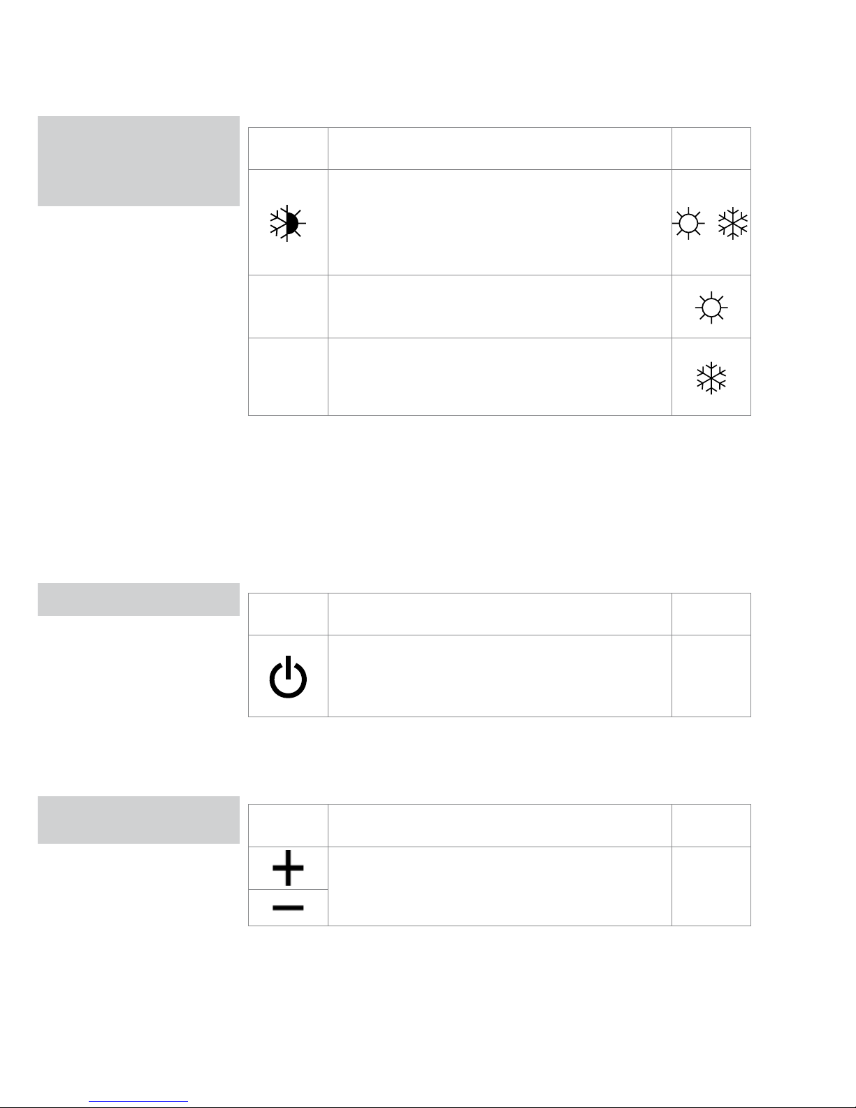
IMPOSTAZIONE
MODALITÀ
RISCALDAMENTO/
RAFFREDDAMENTO
STAND-BY
FUNZIONAMENTO
FUNZIONAMENTO
FUNZIONAMENTO
Pulsante Operazione Display
Tenere premuto il pulsante riscaldamento /
raffreddamento per circa 2 secondi per alternare
la modalità di funzionamento fra riscaldamento e
raffreddamento. L’attivazione della modalità viene
indicata dalla comparsa del rispettivo simbolo sul display.
In modalità riscaldamento, il simbolo rimane
visualizzato fintanto che il valore impostato è
superiore alla temperatura ambiente e scompare.
In modalità raffreddamento, il simbolo rimane
visualizzato fintanto che il valore impostato è inferiore
alla temperatura ambiente e scompare quando il
valore impostato è superiore.
Se uno dei due simboli lampeggia, significa che la temperatura dell’acqua
(calda o fredda) non è adeguata. Il ventilatore si arresta fino a quando la
temperatura dell’acqua non è sufficiente a raggiungere la temperatura
ambiente richiesta. Se, dopo aver dato tensione, la scheda rileva il sensore
di temperatura dell’acqua , l’avvio avviene in condizioni normali con soglie
di minima e massima. La scheda prevede anche il funzionamento privo di
sensore di temperatura dell’acqua; in questo caso, le soglie di arresto del
ventilatore vengono ignorate.
Pulsante Operazione Display
Tenere premuto il pulsante ON/Stand-by per circa
2 secondi. Se sul display non appare alcun simbolo
luminoso significa che il sistema è in stand-by
(nessuna funzione in uso).
Off
Quando l’apparecchio è impostato su questa modalità, l’antigelo è in ogni
caso garantito. Se la temperatura ambiente scende al di sotto dei 5 °C,
vengono attivate le elettrovalvole dell’uscita dell’acqua calda e della caldaia.
Pulsante Operazione Display
Impostare la temperatura ambiente desiderata
utilizzando i pulsanti +/-. Il valore appare sul display
a 3 cifre.
20.5
Il range di regolazione è compreso tra 16 e 28 °C, selezionabili a intervalli di
0,5 °C. Sono consentiti anche valori al di fuori del range, da 5 °C a 40 °C
(tranne in modalità automatica). Impostare questi valori solo per brevi periodi,
poi selezionare un valore intermedio. Il comando è molto preciso: impostare
il valore desiderato e attendere che si autoregoli in funzione dell’effettiva
temperatura ambiente rilevata.
IMPOSTAZIONE DELLA
TEMPERATURA
05 IMPOSTAZIONE MODALITÀ RISCALDAMENTO/RAFFREDDAMENTO / STAND-BY
Page 59
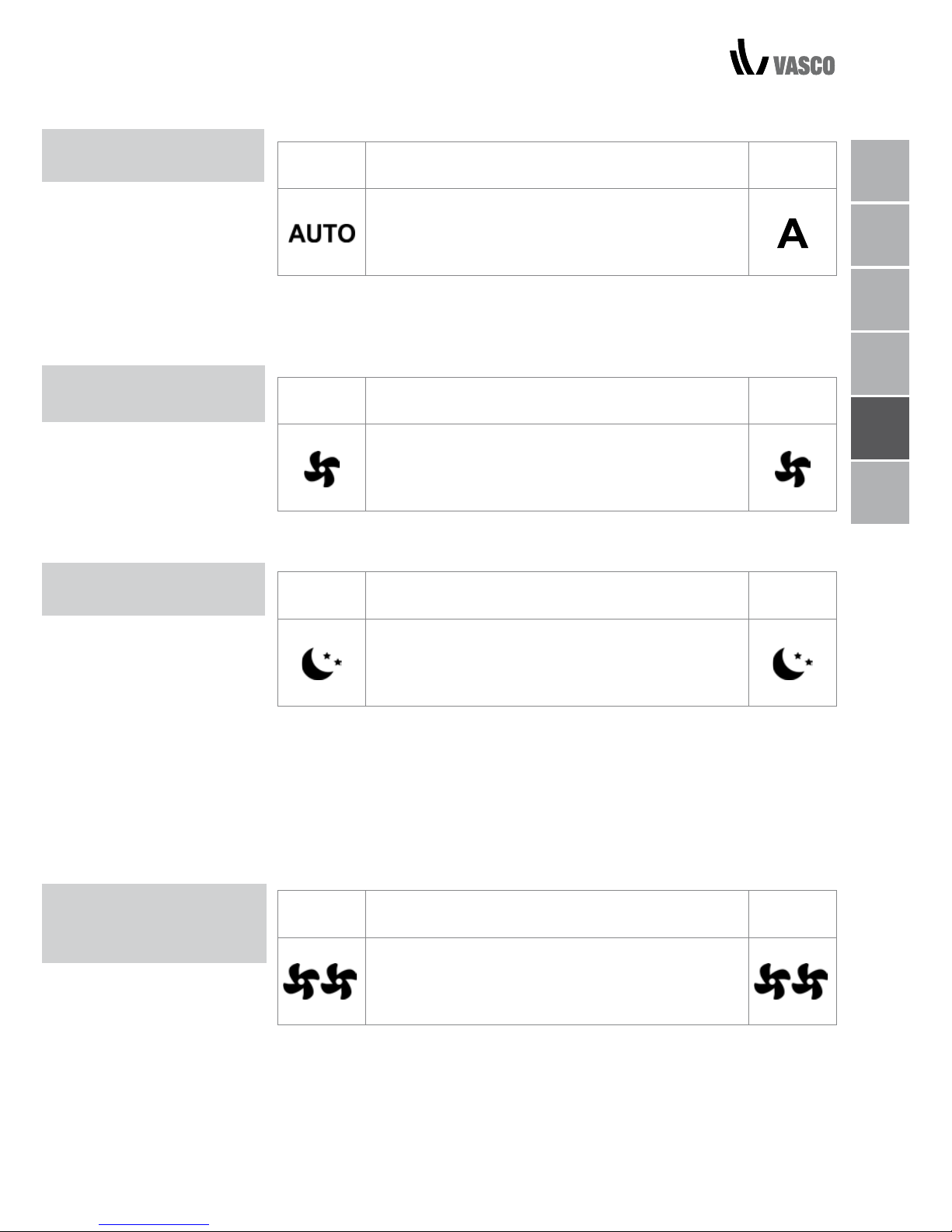
FUNZIONAMENTO AUTOMATICO / SILENZIOSO / NOTTURNO 06
FUNZIONAMENTO
AUTOMATICO
FUNZIONAMENTO
SILENZIOSO
FUNZIONAMENTO
NOTTURNO
FUNZIONAMENTO ALLA
MASSIMA VELOCITÀ DI
VENTILAZIONE
Pulsante Operazione Display
Tenere premuto il tasto AUTO. L’attivazione della
funzione viene indicata dalla comparsa del relativo
simbolo sul display.
La regolazione della velocità di ventilazione viene effettuata automaticamente
tra i valori minimo e massimo, in base alla differenza tra la temperatura
ambiente e quella impostata, secondo un algoritmo di tipo PI.
Pulsante Operazione Display
Tenere premuto il tasto SILENZIOSO. L’attivazione
della funzione viene indicata dalla comparsa del
relativo simbolo sul display.
La velocità di ventilazione è limitata a un valore massimo più contenuto.
Pulsante Operazione Display
Tenere premuto il pulsante Funzionamento
notturno. L’attivazione della funzione viene indicata
dalla comparsa del relativo simbolo sul display.
Selezionando questa modalità, la velocità di ventilazione viene limitata
a un livello molto basso e la temperatura impostata viene regolata
automaticamente, come segue:
- diminuisce di 1 °C dopo un’ora e di un altro grado dopo due ore in
modalità riscaldamento;
- aumenta di 1 °C dopo un’ora e di un altro grado dopo due ore in modalità
raffreddamento;
Pulsante Operazione Display
Tenere premuto il pulsante Funzionamento Max.
L’attivazione della funzione viene indicata dalla
comparsa del relativo simbolo sul display.
Il range di regolazione è compreso tra 16 e 28 °C, selezionabili a intervalli di
0,5 °C. Sono consentiti anche valori al di fuori del range, da 5 °C a 40 °C
(tranne in modalità automatica). Impostare questi valori solo per brevi periodi,
poi selezionare un valore intermedio. Il comando è molto preciso: impostare
il valore desiderato e attendere che si autoregoli in funzione dell’effettiva
temperatura ambiente rilevata.
NL
FR
DE
EN
IT
PL
Page 60
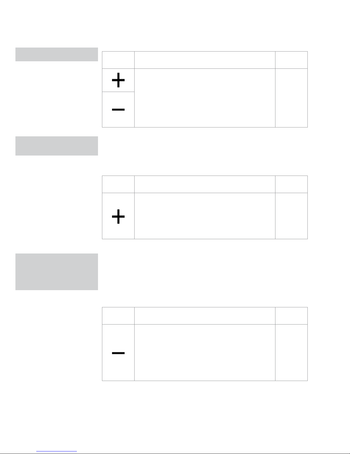
07 BLOCCO PULSANTI / RIDUZIONE DELLA LUMINOSITÀ / DISATTIVAZIONE
BLOCCO PULSANTI
SPEGNIMENTO PER
LUNGHI PERIODI
Pulsante Operazione Display
Premendo contemporaneamente i pulsanti + e - per
3 secondi si bloccano tutti i pulsanti a livello locale e
sul display viene visualizzato “bL”.
Tutte le azioni sono disattivate per l’utente e, ogni
volta che viene premuto un pulsante qualsiasi,
appare la scritta “LOC”. Per sbloccare i pulsanti,
ripetere la sequenza.
bL
Dopo 20 secondi dall’ultima azione la luminosità del pannello diminuisce per
un migliore comfort durante le ore notturne e sul display viene visualizzata
la temperatura ambiente. Se la luminosità è ancora fastidiosa, è possibile
spegnere completamente il display.
Pulsante Operazione Display
Quando il display è spento, tenere premuto
il pulsante + per 5 secondi finché non verrà
visualizzato “01”.
Utilizzare il pulsante - per impostare il valore su
00, quindi attendere 20 secondi per verificare che
l’impostazione sia stata accettata.
00
Poiché il sensore di rilevazione si trova nella parte inferiore del dispositivo, la
temperatura rilevata può a volte differire dalla temperatura reale. Utilizzando
questa funzione, il valore visualizzato può essere regolato in un range da
-9/+12 K in intervalli di 0,1 °C. Regolare con cautela e solo dopo avere
effettivamente rilevato una discrepanza rispetto alla temperatura reale
utilizzando uno strumento affidabile!
Pulsante Operazione Display
Con il display spento, premere e tenere premuto
per 5 secondi il tasto - per accedere al menu di
regolazione (utilizzando i tasti + e -) dell'offset della
sonda dell'aria (AIR) visualizzato da - 9 a +12 K in
intervalli da 0.1 K.
Dopo 20 secondi dall'ultima azione, il quadro si
spegne e l'impostazione viene memorizzata.
00.0
RIDUZIONE DELLA
LUMINOSITÀ AL MINIMO
REGOLAZIONE DEL
SENSORE DI
TEMPERATURA
AMBIENTE
Page 61
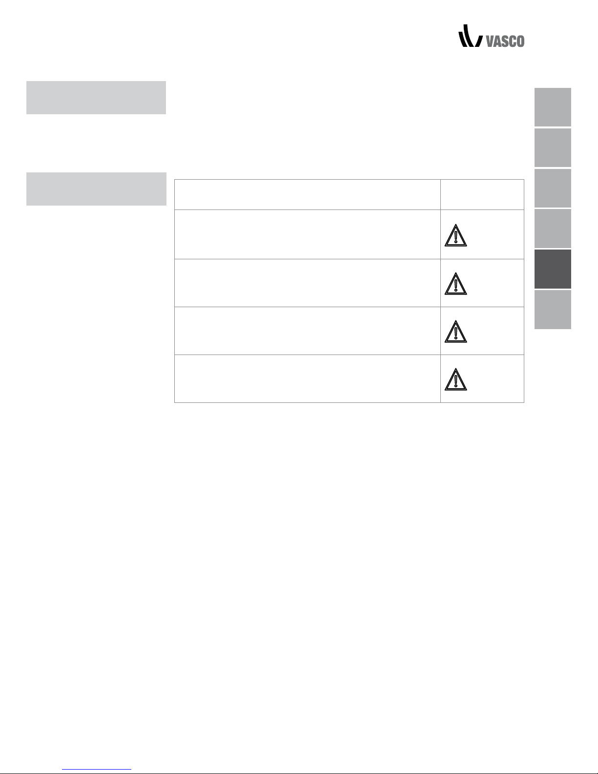
SPEGNIMENTO PER LUNGHI PERIODI / SEGNALI DI ERRORE 08
SPEGNIMENTO PER
LUNGHI PERIODI
SEGNALI
DI ERRORE
In caso di spegnimento stagionale o per le vacanze, procedere come segue:
- disattivare l’apparecchio
- spegnere l’interruttore generale dell’unità.
La funzione antigelo non è attiva.
Errore Display
Sonda temperatura ambiente difettosa (aria, AIR).
E1
Problema al motore del ventilatore (ad es. inceppamento
causato da corpi estranei, guasto al sensore di rotazione).
E2
Guasto al sensore di temperatura dell’acqua per le
versioni a 2 tubi (H2). In questo caso, assicurarsi che il
sensore installato sia da 10 kΩ.
E3
Azionamento del microinterruttore della griglia (S1) dovuto
alle operazioni di pulizia del filtro.
Gr
NL
FR
DE
EN
IT
PL
Page 62
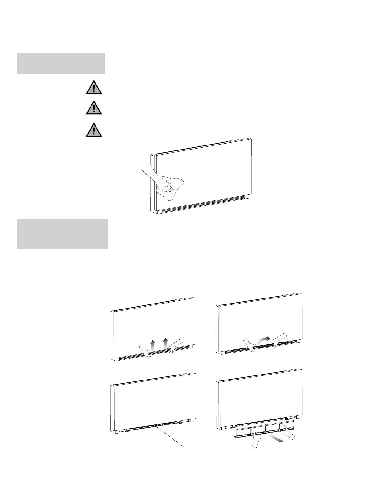
09 EPULIZIA ESTERNA / PULIZIA DEL FILTRO ASPIRAZIONE ARIA
PULIZIA
ESTERNA
Scollegare l’unità dall’alimentazione prima di ogni intervento di pulizia e
manutenzione, ruotando su off l’interruttore generale.
Attendere il raffreddamento dei componenti per evitare eventuali scottature.
Non utilizzare spugne abrasive o detergenti abrasivi o corrosivi per evitare di
danneggiare le superfici verniciate.
Se necessario, pulire le superfici esterne del ventilconvettore con un panno
morbido e inumidito.
Pulire il filtro dell’aria dopo un periodo di utilizzo continuativo e in base alla
concentrazione di impurità nell’aria, oppure quando si desidera riavviare
l’apparecchio dopo un periodo di inattività. Procedere come descritto di
seguito.
RIMOZIONE DELLE CELLE FILTRANTI
- Estrarre il filtro tirandolo verso l’esterno in senso orizzontale.
2 MANUTENZIONE
PULIZIA DEL FILTRO
DI ASPIRAZIONE
DELL’ARIA
estrazione del filtro
A
B
C
D
Page 63
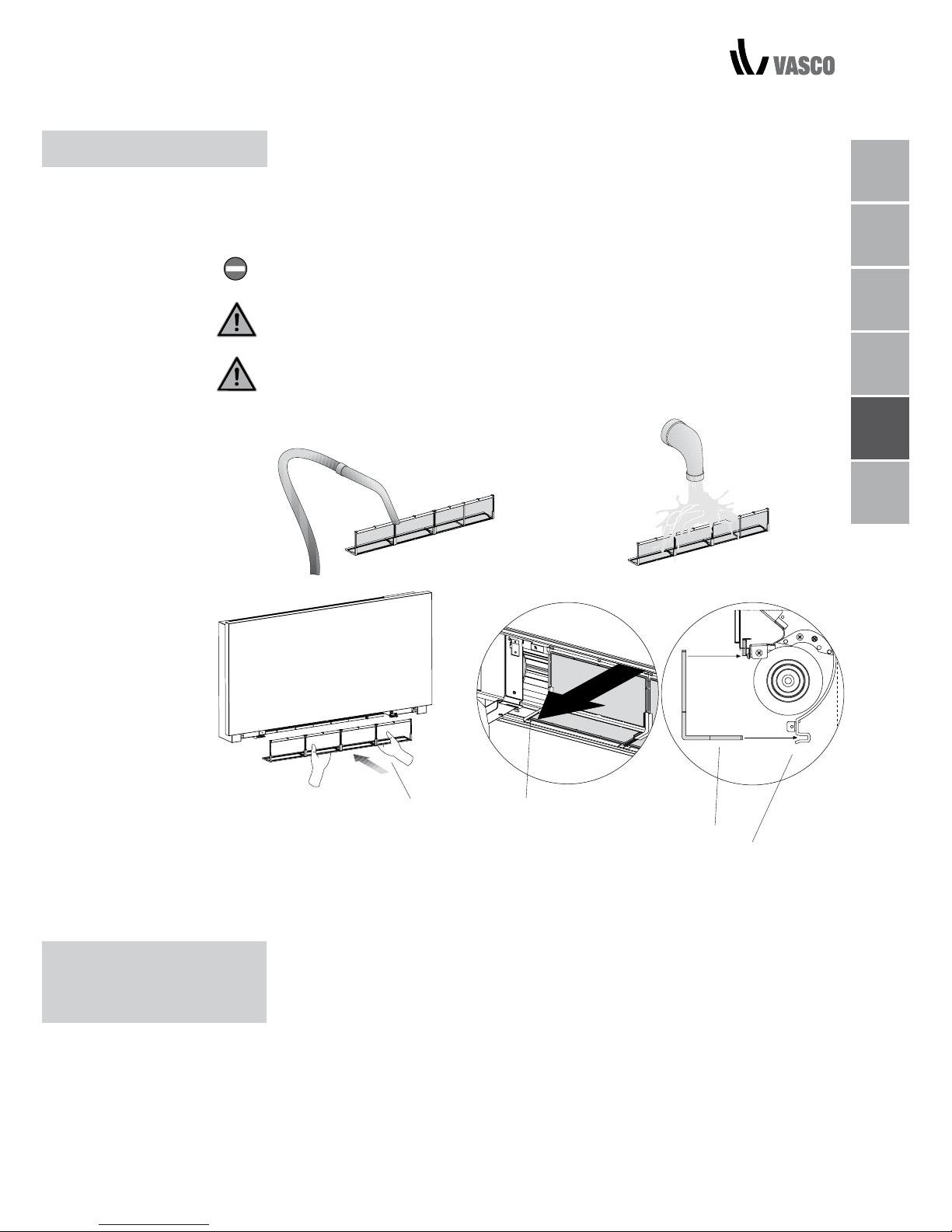
PULIZIA DEI FILTRI / SUGGERIMENTI PER IL RISPARMIO ENERGETICO 10
A Filtro
B Bordo inferiore
C Alloggiamento del filtro
- Rimuovere la polvere dal filtro con un aspirapolvere.
- Lavare il filtro con acqua corrente senza utilizzare detergenti o solventi e
lasciare asciugare.
- Rimontare il filtro sul ventilconvettore, prestando particolare attenzione a
inserire il bordo inferiore nel suo alloggiamento.
Non utilizzare l’apparecchio senza il filtro a rete.
L’apparecchio è dotato di un interruttore di sicurezza che impedisce il
funzionamento del ventilatore in assenza della griglia.
Dopo la pulizia del filtro, verificare che la griglia sia montata correttamente.
PULIZIA DEI FILTRI
- Assicurarsi che i filtri vengano puliti regolarmente;
- Tenere le porte e le finestre chiuse il più possibile nelle stanze da climatizzare;
- In estate, limitare la luce diretta del sole per quanto possibile negli ambienti
da climatizzare (utilizzando tende, tapparelle, ecc.).
SUGGERIMENTI
PER IL RISPARMIO
ENERGETICO
NL
FR
DE
EN
IT
PL
A
B
B
C
Page 64

3 RISOLUZIONE DEI PROBLEMI
RISOLUZIONE
DEI PROBLEMI
In caso di perdite di acqua o funzionamento anomalo, scollegare
immediatamente l’alimentazione elettrica e chiudere tutti i rubinetti dell’acqua.
Qualora si riscontrasse una delle seguenti anomalie, contattare un centro di
assistenza autorizzato o personale qualificato e non intervenire personalmente.
- La ventilazione non si attiva nemmeno in presenza di acqua calda o fredda
nel circuito idraulico.
- L’apparecchio perde acqua durante il riscaldamento.
- L’apparecchio perde acqua solo durante il raffreddamento.
- L’apparecchio emette un rumore eccessivo.
- Si sta formando ruggine sul pannello anteriore.
11 RISOLUZIONE DEI PROBLEMI
Page 65
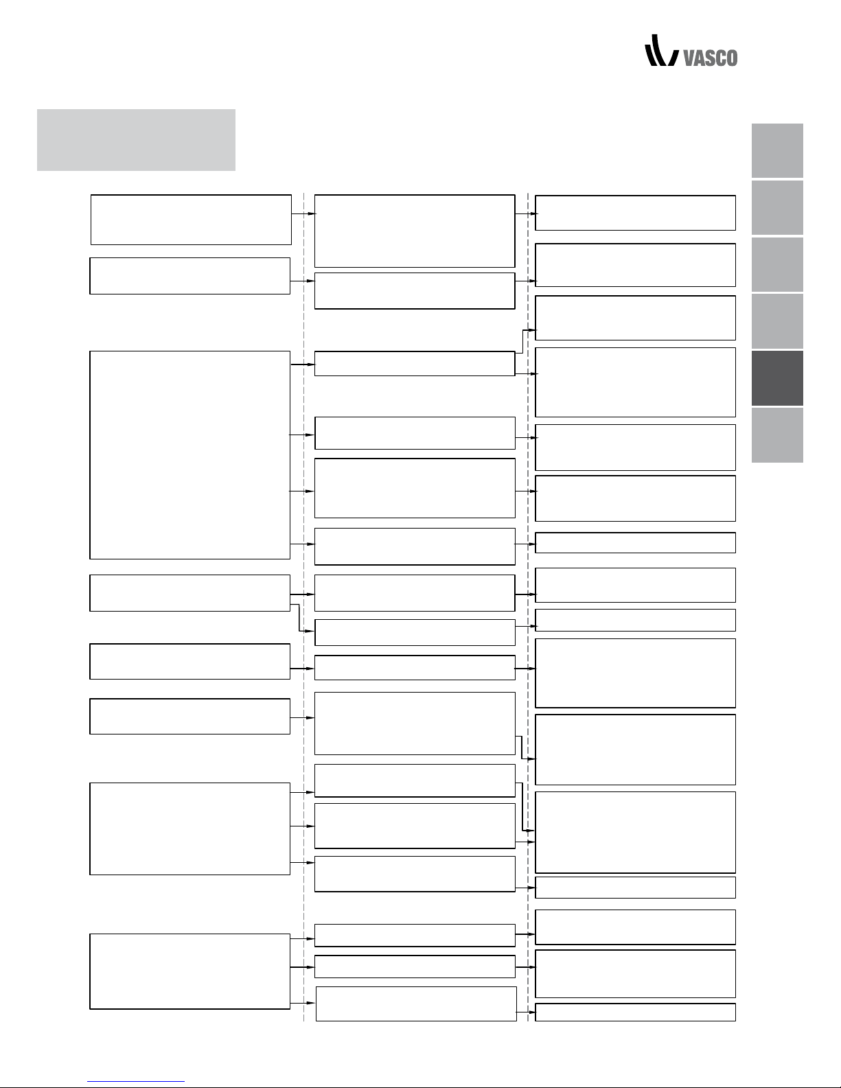
TABELLA DI
RISOLUZIONE DEI
PROBLEMI
TABELLA DI RISOLUZIONE DEI PROBLEMI 12
NL
FR
DE
EN
IT
PL
EFFETTO
CAUSA
RIMEDIO
La valvola del circuito necessita
di un po’ di tempo per aprirsi, di
conseguenza occorre del tempo
affinché l’acqua calda o fredda
circoli nell’apparecchio
Attendere 2 o 3 minuti prima di
aprire la valvola del circuito.
La ventilazione si attiva in ritardo
rispetto alle nuove impostazioni di
temperatura o funzione.
Nel sistema non circola acqua
calda né fredda.
La valvola idraulica rimane chiusa.
Controllare che la caldaia o il
sistema di raffreddamento
funzionino correttamente.
Smontare il corpo valvola e verificare il ripristino della circolazione
dell’acqua.
L’apparecchio non attiva la
ventilazione.
La ventilazione non si attiva nemmeno in presenza di acqua calda
o fredda nel circuito idraulico.
Verificare l’efficienza delle prestazioni
della valvola alimentandola separatamente a 230 V AC. Se si attiva,
il problema potrebbe dipendere dal
controllo elettronico.
Il motore del ventilatore è in
blocco o si è fuso.
Verificare gli avvolgimenti del
motore e che il ventilatore possa
girare liberamente.
Il micro-interruttore che interrompe la ventilazione quando la griglia
del filtro è aperta non si chiude
correttamente.
Verificare che chiudendo la griglia
si attivi il contatto del microinterruttore.
I collegamenti elettrici non sono
corretti.
Verificare i collegamenti elettrici.
Perdite nei collegamenti idraulici
del sistema.
Verificare la tenuta e serrare i
collegamenti fino in fondo.
L’apparecchio perde acqua durante la funzione di riscaldamento.
Perdite nel gruppo valvola.
Verificare lo stato delle guarnizioni.
Verificare il corretto posizionamento
dell’isolamento termo-acustico,
prestando particolare attenzione a
quello posizionato sul lato anteriore,
sopra alla batteria alettata.
Si formano gocce di condensa sul
pannello anteriore.
Isolamento termico staccato.
Non appena il tasso di umidità inizia
a scendere il fenomeno scompare.
In ogni caso la presenza di poche
gocce di acqua nell’apparecchio
non indica un malfunzionamento.
Vi sono gocce d’acqua sulla
griglia di fuoriuscita dell’aria.
In situazioni di elevata umidità
(>60%) si potrebbe formare
condensa, soprattutto a velocità
di ventilazione minime.
Versare lentamente una bottiglia
d’acqua sulla parte inferiore della
batteria per verificare il drenaggio;
se necessario, pulire la vaschetta
e/o aumentare l’inclinazione del
tubo di drenaggio.
L’apparecchio perde acqua solo
durante la funzione di
raffreddamento.
La vaschetta della condensa è
bloccata.
Per il corretto drenaggio dello scarico della condensa non occorre
alcuna inclinazione.
I tubi di collegamento e il gruppo
valvola non sono ben isolati.
Verificare l’isolamento dei tubi.
L’apparecchio emette un rumore
strano.
Il ventilatore colpisce la struttura.
Il ventilatore è sbilanciato.
Verificare se i filtri sono intasati e
pulirli se necessario
Verificare se i filtri sono intasati e
purliri se necessario.
Lo sbilanciamento provoca
vibrazioni eccessive del macchinario; sostituire il ventilatore.
Pulire i filtri.
Page 66

13 CONDIZIONI DI GARANZIA / DICHIARAZIONE DEL PRODUTTORE
4 CONDIZIONI DI GARANZIA
Vasco dichiara di garantire il prodotto Vasco Niva FC per due anni a partire dalla data
di acquisto. La data riportata sulla fattura dell’azienda che si occupa dell’installazione
comprova la data d’acquisto. Se non è stata emessa alcuna fattura, la data di produzione verrà considerata come data di acquisto. La garanzia include unicamente la
sostituzione delle parti di ricambio, del ventilatore e della scheda stampata elettronica.
Per le parti di ricambio non sono previsti ulteriori periodi di garanzia. La garanzia non
copre:
• I costi di montaggio e smontaggio
• I difetti che, a nostro parere, derivano da manipolazioni improprie, negligenze
o incidenti
• I difetti che derivano da manipolazioni o riparazioni effettuate da terze parti
senza il nostro permesso
• I difetti che derivano da manutenzione irregolare e/o non professionale
• I difetti che derivano dall’uso dell’unità in un ambiente non adatto
La garanzia decade nel caso in cui l’FCU venga utilizzata alle condizioni di cui sopra.
L’installatore deve contattare Vasco per verificare le modalità di restituzione dei componenti difettosi. L’installatore riceverà un codice per il reso in garanzia. Le spedizioni a
Vasco dei componenti difettosi devono riportare questo codice per il reso.
Kruishoefstraat 50, B-3650 Dilsen
T. +32 (0)89 79 04 11
F. +32 (0)89 79 05 00
[email protected]
www.vasco.eu
MANUFACTURER’S DECLARATION
Vasco dichiara che l’FCU è provvista di marcatura CE ed è stata progettata,
prodotta e commercializzata nel rispetto delle seguenti norme dell’Unione
Europea: Direttiva sulla bassa tensione 2014/35/EU e successive norme tecniche:
EN 60335-2-40:2003 + A11:2004 + A12:2005 + A1:2006 + EC:2006
+ A2:2009 + A13:2012 + A13/EC:2013, EN 60335-1:2002 + A11:2004
+ A1:2004 + A12:2006 + A2:2006+ A1/EC:2007 + A13:2008 + EC:2009
+ EC:2010 + A14:2010 + A15:2011
Direttiva EMC 2014/30/EU e successive norme tecniche:
EN 60335-1:2012, EN 55014-1:2006 + A1:2009 + A2:2011,
EN 61000-3-2:2006 + A1:2009 + A2:2009, EN 61000- 3-3:2013,
EN 55014-2:1997 + A1:2001 + A2:2008
Direttiva RoHS 2011/65/EU
Vasco Group nv
Dilsen, België, agosto 2017
P. Nijs, amministratore delegato
Page 67

NL
FR
DE
EN
IT
PL
SPIS TREŚCI
1 INFORMACJE OGÓLNE
Elektroniczny panel sterowania 3
Główny włącznik 3
Aktywacja 4
Wybór pracy w trybie ogrzewania / chłodzenia 5
Czuwanie 5
Wybór temperatury 5
Praca automatyczna 6
Praca cicha 6
Praca w nocy 6
Praca z maksymalną prędkością nawiewu 6
Blokada 7
Redukcja jasności do minimum 7
Dezaktywacja 7
Korekta czujnika temperatury w pomieszczeniu 7
Wyłączanie urządzenia na dłuższy czas 8
Sygnały błędu 8
2 KONSERWACJA
Czyszczenie od zewnątrz 9
Czyszczenie filtra zasysającego 9
Czyszczenie filtrów 10
Wskazówki dotyczące oszczędzania energii 10
3 ROZWIĄZYWANIE PROBLEMÓW
Wykrywanie problemów 11
Tabela rozwiązywania problemów 12
4 WARUNKI GWARANCJI
Warunki gwarancji 13
SPIS TREŚCI 01
Page 68
02 ZGODNOŚĆ / SYMBOLE / PIKTOGRAMY PRZEZNACZENIA / PIKTOGRAMY BEZPIECZEŃSTWA
Produkt jest zgodny z niżej wymienionymi dyrektywami europejskimi:
• Dyrektywa niskonapięciowa 2014/35/EU
• Dyrektywa kompatybilności elektromagnetycznej 2014/30/EU;
Użyte w kolejnym rozdziale piktogramy przekazują informacje niezbędne do
poprawnej, wygodnej i bezpiecznej obsługi urządzenia.
PIKTOGRAMY BEZPIECZEŃSTWA
Ryzyko obrażeń ciała
Informacja dla personelu, zgodnie z którą dana operacja może spowodować
obrażenia w przypadku niezastosowania się do zasad bezpieczeństwa.
Niebezpieczeństwo związane z wysokim napięciem
Informacja dla personelu, zgodnie z którą dana operacja może spowodować
porażenie prądem w przypadku niezastosowania się do zasad bezpieczeństwa.
Niebezpieczeństwo związane z wysoką temperaturą
Informacja dla personelu, zgodnie z którą dana operacja może spowodować
poparzenie w przypadku niezastosowania się do zasad bezpieczeństwa.
Czynność zabroniona
Informacja o czynnościach surowo wzbronionych.
ZGODNOŚĆ
SYMBOLE
Page 69
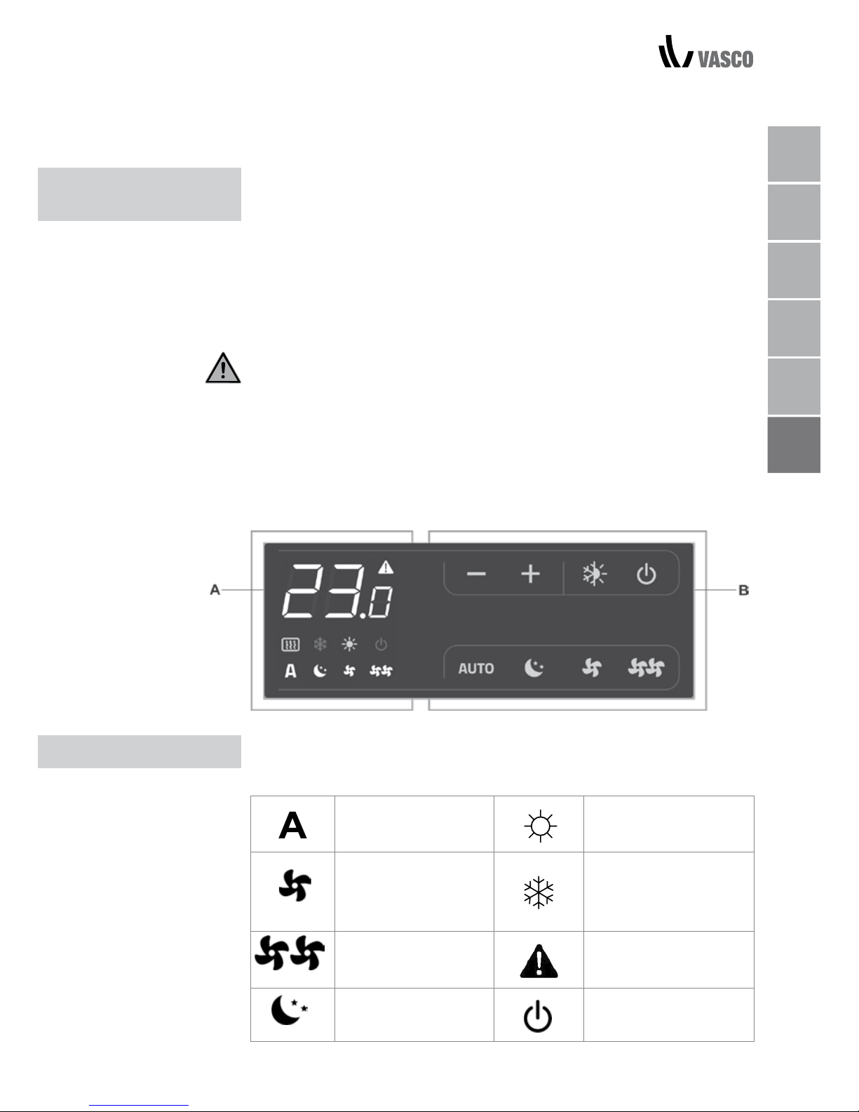
NL
FR
DE
EN
IT
PL
Ten element urządzenia pozwala na w pełni autonomiczną regulację
temperatury powietrza w pomieszczeniu (wartości parametrów można
wprowadzać z klawiatury) z wykorzystaniem programów AUTO
(„automatyczny”), SILENT („cichy”), NIGHT („noc”) oraz MAX („maksymalny”)
z wykorzystaniem czujnika umieszczonego w dolnej części urządzenia,
zapewniającej zabezpieczenie przed zamarzaniem nawet w czasie, kiedy
urządzenie pozostaje w trybie czuwania. Panel sterowania wyposażony jest
w pamięć, dzięki czemu po wyłączeniu urządzenia lub odłączeniu go od
zasilania ustawienia nie zostają utracone.
Po 20 sekundach bezczynności, jasność ekranu panelu sterowania zostaje
zredukowana w celu zwiększonego komfortu nocnego użytkowania, a na
wyświetlaczu pojawi się informacja o temperaturze. Naciśnij dowolny przycisk,
aby przywrócić maksymalny poziom jasności.
Czujnik temperatury wody, umieszczony w konwektorze urządzenia, reguluje
minimalny poziom temperatury w czasie grzania (28oC) oraz maksymalny
poziom temperatury w czasie chłodzenia (20oC).
Informacje o stanie urządzenia oraz komunikaty alarmowe pojawiają się na
wyświetlaczu w formie 8 symboli:
Praca automatyczna Ogrzewanie włączone
Praca cicha Chłodzenie włączone
Maksymalna prędkość
nawiewu
Sygnalizacja alarmowa
(stałe światło)
Praca w nocy
Wskaźnik wyłączenia
panelu
1 INFORMACJE OGÓLNE
ELEKTRONICZNY
PANEL STEROWANIA
WYŚWIETLACZ
A wyświetlacz
B przyciski
PANEL STEROWANIA / WYŚWIETLACZ 03
Page 70
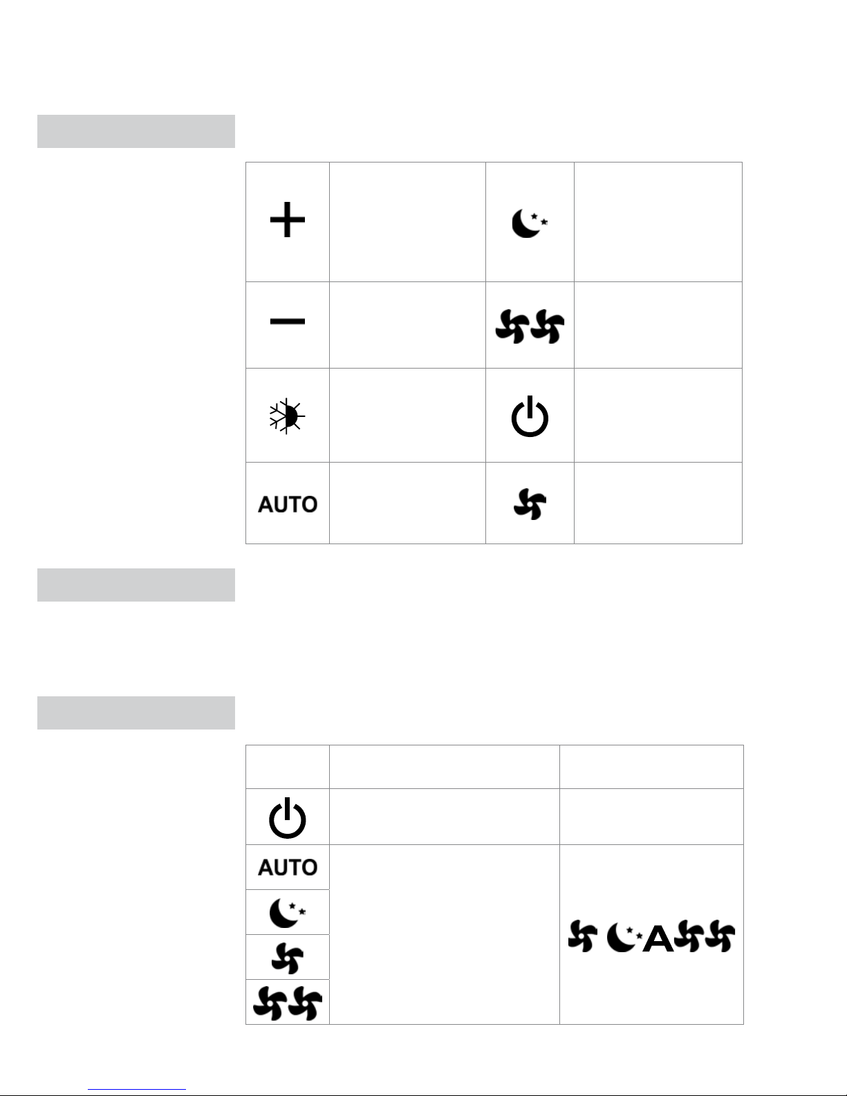
Funkcje ustawiane są za pomocą niżej wymienionych 8 podświetlanych
przycisków:
Temp +
służy do podwyższania
poziomu zadanej
temperatury
Działanie w nocy:
ogranicza prędkość
nawiewu do określonego
poziomu; zadana
temperatura zmienia się
automatycznie.
Temp służy do obniżania
poziomu zadanej
temperatury
Działanie z maksymalną
szybkością: pozwala na
ustawienie maksymalnej
prędkości nawiewu
Grzanie/chłodzenie:
przełącza tryb pracy
pomiędzy grzaniem a
chłodzeniem
WŁĄCZONE / tryb
czuwania: służy do
aktywacji urządzenia lub
do przełączania go w
tryb czuwania.
Przełącza regulację
prędkości na tryb
automatyczny
Cisza: zmniejsza
prędkość nawiewu.
Aby sterować urządzeniem za pomocą panelu sterowania, należy je podłączyć
do zasilania. Główny włącznik zainstalowany jest na linii zasilania. Aby
sterować urządzeniem, należy go uruchomić.
- Włącz urządzenie za pomocą głównego włącznika.
Aby aktywować urządzenie, należy użyć niżej opisanych przycisków:
Przycisk Działanie Wyświetlacz
Naciśnij przycisk ON / czuwanie
On („włączony”) lub off
(„wyłączony”)
Wybierz jeden z 4 trybów
działania, naciskając odpowiedni
przycisk.
PRZYCISKI
GŁÓWNY WŁĄCZNIK
AKTYWACJA
04 PRZYCISKI / GŁÓWNY WŁĄCZNIK / AKTYWACJA
Page 71
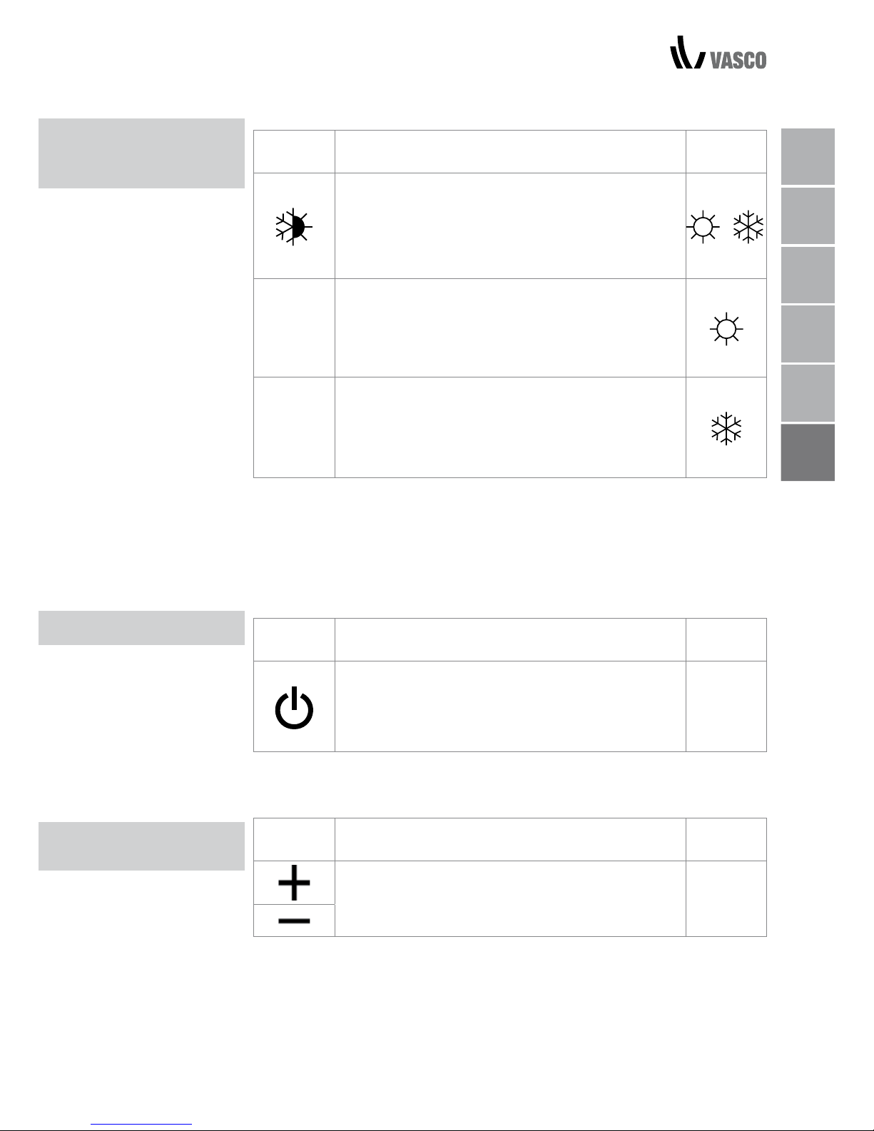
NL
FR
DE
EN
IT
PL
WYBÓR PRACY W
TRYBIE OGRZEWANIA /
CHŁODZENIA
CZUWANIE
Przycisk Działanie
Wyś-
wietlacz
Aby przełączyć z trybu ogrzewania na tryb chłodzenia i odwrotnie, przytrzymaj przycisk ogrzewania/
chłodzenia przez ok. 2 sekundy. Tryby te są oznaczone 2 symbolami, które pojawiają się odpowiednio
w czasie ogrzewania i w czasie chłodzenia.
W czasie ogrzewania, kiedy temperatura zadana
jest wyższa od temperatury otoczenia, wyświetla się
symbol po prawej. Kiedy temperatura zadana jest
niższa od temperatury otoczenia, obydwie funkcje
wyłączają się.
W czasie chłodzenia, kiedy temperatura zadana
jest niższa od temperatury otoczenia, wyświetla się
symbol po prawej. Kiedy temperatura zadana jest
wyższa od temperatury otoczenia, obydwie funkcje
wyłączają się.
Miganie jednego z dwóch symboli oznacza, że temperatura wody (ciepłej lub
zimnej) nie jest wystarczająca, a wentylator wyłącza się do momentu, kiedy
temperatura nie osiągnie zadanego poziomu. Jeżeli po włączeniu urządzenie
wykryje czujnik H2, a temperatura mieści się w zakresie wyznaczonym przez
wartość minimalną i maksymalną, następuje rozpoczęcie pracy.
W przypadku niewykrycia czujnika H2, limity zatrzymujące działanie
wentylatora są przez urządzenie ignorowane.
Przycisk Działanie
Wyś-
wietlacz
Naciśnij przycisk ON / czuwanie i przytrzymaj
go przez ok. 2 sekundy. Brak podświetlonych
komunikatów na wyświetlaczu oznacza, że system
pozostaje w stanie czuwania (nie podejmuje żadnych
Off
wyłączony
Przez cały czas kiedy sterowanie pozostaje w tym trybie, zapewniona jest
ochrona przed zamarzaniem. Kiedy temperatura otoczenia spadnie poniżej
5oC, otwierają się elektrozawory na wyjściu wody ciepłej i bojlerze.)
Przycisk Działanie
Wyś-
wietlacz
Dwa przyciski po lewej pozwalają odpowiednio
obniżyć lub podwyższyć temperaturę zadaną, której
wartość pojawia się na 3-cyfrowym wyświetlaczu.
20.5
Temperaturę można ustawić w zakresie od 16 do 28oC w odstępach
0,5oC (akceptowane są jednak również wartości spoza tego zakresu, pod
warunkiem, że mieszczą się pomiędzy 5oC a 40oC, o ile nie został włączony tryb
automatyczny). Wartości te należy ustawiać tylko na krótki czas, a następnie
należy wybrać wartość z zakresu umiarkowanego. Urządzenie sterujące jest
bardzo precyzyjne – ustaw je na zadaną wartość i czekaj, aż urządzenie samo się
wyreguluje odpowiednio do aktualnie wykrywanej temperatury w pomieszczeniu.
WYBÓR
TEMPERATURY
WYBÓR PRACY W TRYBIE OGRZEWANIA / CHŁODZENIA / CZUWANIE / WYBÓR TEMPERATURY 05
Page 72
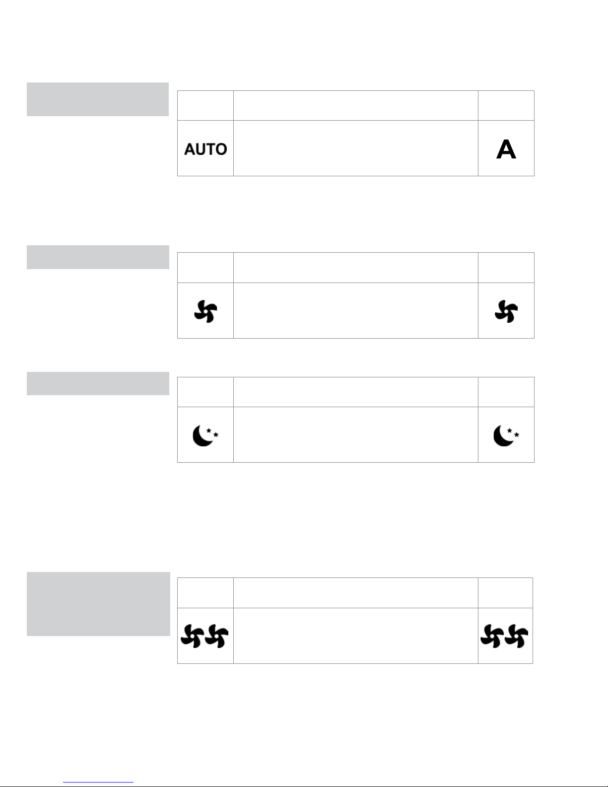
06 PRACA W TRYBIE AUTOMATYCZNYM / PRACA CICHA / PRACA W NOCY
PRACA
AUTOMATYCZNA
SILENT OPERATION
PRACA W NOCY
PRACA Z
MAKSYMALNĄ
PRĘDKOŚCIĄ
NAWIEWU
Przycisk Działanie
Wyś-
wietlacz
Naciśnij i przytrzymaj przycisk AUTO. Aktywowana
funkcja wskazana jest odpowiednim symbolem
pojawiającym się na wyświetlaczu.
Szybkość nawiewu regulowana jest automatycznie w zakresie wyznaczonym
przez wartość minimalną i maksymalną, odpowiednio do różnicy pomiędzy
rzeczywistą temperaturą w pomieszczeniu a temperaturą zadaną, zgodnie z
algorytmem PI.
Przycisk Działanie
Wyś-
wietlacz
Naciśnij i przytrzymaj przycisk Silent (praca cicha).
Aktywowana funkcja wskazana jest odpowiednim
symbolem pojawiającym się na wyświetlaczu.
Szybkość nawiewu jest ograniczona.
Przycisk Działanie
Wyś-
wietlacz
Naciśnij i przytrzymaj przycisk Night-time operation
(praca w nocy). Aktywowana funkcja wskazana
jest odpowiednim symbolem pojawiającym się na
wyświetlaczu.
Wybór tego trybu powoduje znaczne ograniczenie szybkości nawiewu. W tym
trybie temperatura jest regulowana automatycznie zgodnie z niżej opisanym
algorytmem:
- w trybie grzania: podwyższenie o 1oC po godzinie pracy i o kolejny
stopień do dwóch godzinach pracy;
- w trybie chłodzenia: obniżenie o 1oC po godzinie pracy i o kolejny stopień
do dwóch godzinach pracy;
Przycisk Działanie
Wyś-
wietlacz
Naciśnij i przytrzymaj przycisk Max operation
(praca z maksymalną szybkością). Aktywowana
funkcja wskazana jest odpowiednim symbolem
pojawiającym się na wyświetlaczu.
W tym trybie wentylator pracuje z maksymalną szybkością zarówno w
czasie ogrzewania jak i w czasie chłodzenia. Po osiągnięciu odpowiedniej
temperatury w pomieszczeniu zalecamy wybór jeden z pozostałych
3 trybów działania – pozwoli to na ograniczenie poziomu hałasu i zwiększenie
komfortu użytkowania urządzenia.
Page 73
NL
FR
DE
EN
IT
PL
BLOKADA URZĄDZENIA / REDUKCJA POZIOMU JASNOŚCI / REGULACJA TEMPERATURY 07
BLOKADA
Przycisk Działanie
Wyś-
wietlacz
Po przytrzymaniu przycisków + i – przez 3 sekundy
wszystkie przyciski są lokalnie zablokowane, a
na wyświetlaczu pojawia się „bL”. Użytkownik nie
może wykonywać żadnych działań, a w momencie
naciśnięcia jakiegokolwiek przycisku pojawia się
„LOC”. Aby odblokować przyciski należy powtórzyć
procedurę.
bL
Po 20 sekundach od ostatniego działania jasność panelu zmniejszy się, aby
poprawić komfort użytkowania urządzenia w nocy, a na ekranie wyświetli się
informacja o temperaturze pomieszczenia. Jeżeli światło w dalszym ciągu
przeszkadza, można całkowicie wyłączyć wyświetlacz.
Przycisk Działanie
Wyś-
wietlacz
Kiedy wyświetlacz jest wyłączony, należy przytrzymać
przycisk + na 5 sekund, aż pojawi się „01”. Zmień
wartość na 00 za pomocą przycisku - i odczekaj 20
sekund, aby upewnić się, że nowe ustawienie zostało
zaakceptowane.
00
Ponieważ czujnik temperatury znajduje się w dolnej części urządzenia, odczyt
temperatury może różnić się od rzeczywistej temperatury w pomieszczeniu.
Funkcja ta pozwala na ustawienie temperatury w zakresie od -9 do 12 K w
odstępach 0,1oC. Należy z niej korzystać ostrożnie i używać jej wyłącznie
w momencie wykrycia różnicy w stosunku do rzeczywistej temperatury w
pomieszczeniu za pomocą wiarygodnego urządzenia.
Przycisk Operation
Wyś-
wietlacz
Kiedy wyświetlacz jest wyłączony, naciśnij i
przytrzymaj przycisk + przez 5 sekund, aż wyświetli
się „01”. Za pomocą przycisku - zmień wartość na
00 i odczekaj 20 sekund, aby upewnić się, że nowa
wartość została przyjęta.
00.0
REDUKCJA JASNOŚCI
DO MINIMUM
KOREKTA CZUJNIKA
TEMPERATURY W
POMIESZCZENIU
Page 74
08 WYŁĄCZANIE NA DŁUŻSZY CZAS / SYGNAŁY BŁĘDÓW
WYŁĄCZANIE
URZĄDZENIA NA
DŁUŻSZY CZAS
SYGNAŁY BŁĘDU
Przy wyłączaniu na dłuższy okres lub na wakacje, należy wykonać poniższą
procedurę:
- dezaktywować urządzenie;
- wyłączyć urządzenie za pomocą głównego włącznika.
W wyłączonym urządzeniu funkcja zabezpieczenia przed zamarzaniem nie
działa.
Błąd
Komunikat na
wyświetlaczu
Awaria czujnika temperatury powietrza w pomieszczeniu.
E1
Problem z silnikiem wentylatora (np. blokada
spowodowana obcym obiektem, awaria czujnika
obrotów).
E2
Awaria czujnika temperatury wody w systemie
dwururowym (H2). W takiej sytuacji należy upewnić się,
że opór czujnika temperatury wynosi 10 kΩ.
E3
Aktywacja mikroprzełącznika kratki S1 w czasie operacji
czyszczenia filtra.
Gr
CZYSZCZENIE
OD ZEWNĄTRZ
CZYSZCZENIE FILTRA
ZASYSAJĄCEGO
Page 75
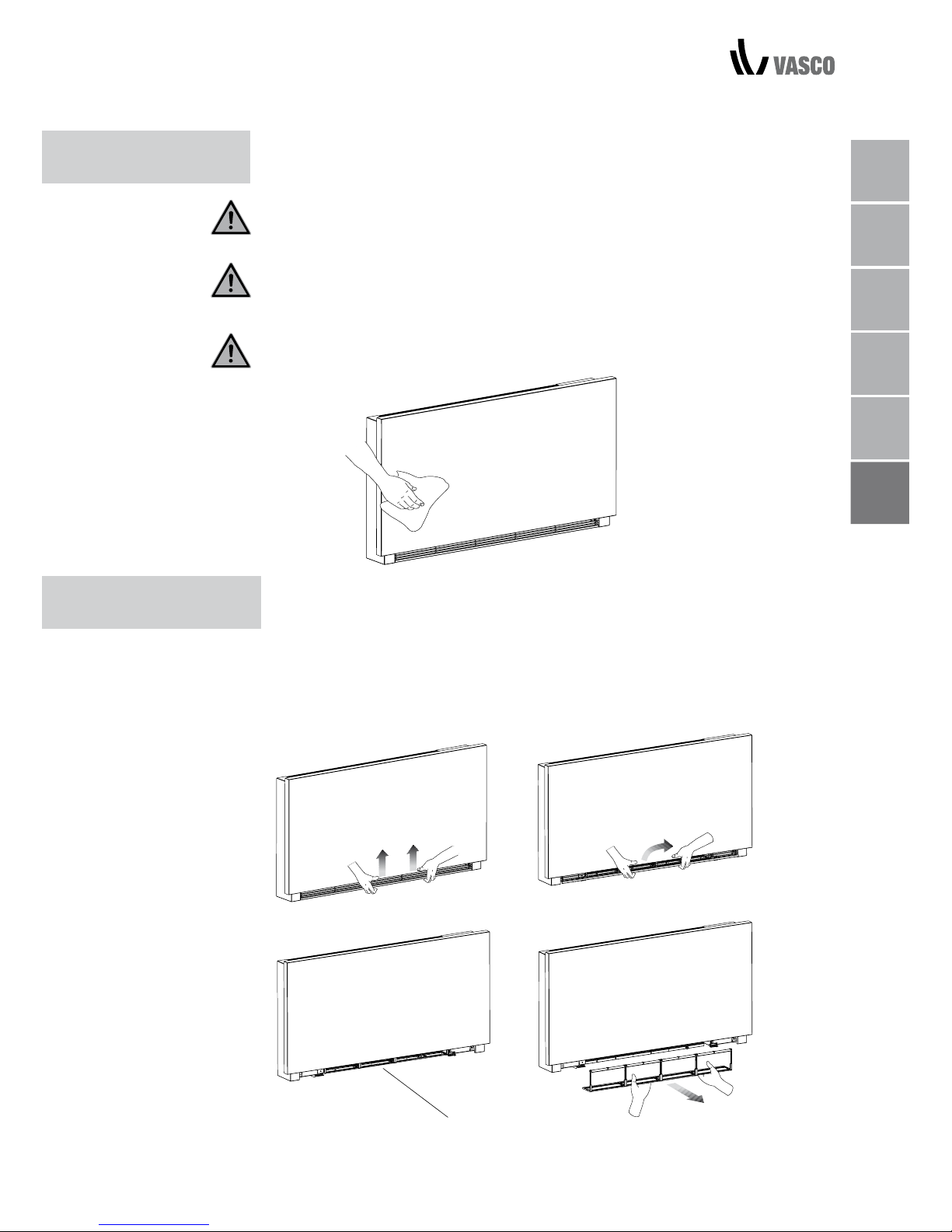
NL
FR
DE
EN
IT
PL
CZYSZCZENIE ZEWNĘTRZNE / CZYSZCZENIE FILTRA ZASYSAJĄCEGO 09
CZYSZCZENIE
OD ZEWNĄTRZ
Przed rozpoczęciem jakichkolwiek operacji związanych z czyszczeniem i
konserwacją należy odłączyć urządzenie od zasilania za pomocą głównego
wyłącznika.
Aby uniknąć ryzyka poparzenia, poczekaj, aż wszystkie części urządzenia
ostygną.
Aby uniknąć zniszczenia powierzchni pokrytych farbą, nie używaj ściernych
gąbek, detergentów z dodatkami ściernymi ani detergentów powodujących
korozję.
W razie konieczności oczyść zewnętrzną powierzchnię klimakonwektora za
pomocą miękkiej, wilgotnej szmatki.
Czyść filtr po okresie ciągłej eksploatacji urządzenia, w zależności od poziomu
czystości powietrza; wykonuj poniższą procedurę również wtedy, kiedy chcesz
uruchomić urządzenie po pewnym czasie niekorzystania z niego.
WYJMOWANIE ELEMENTÓW FILTRUJĄCYCH
- wyciągnij filtr ciągnąc poziomo na boki.
2 KONSERWACJA
CZYSZCZENIE FILTRA
ZASYSAJĄCEGO
A
B
C
D
Page 76
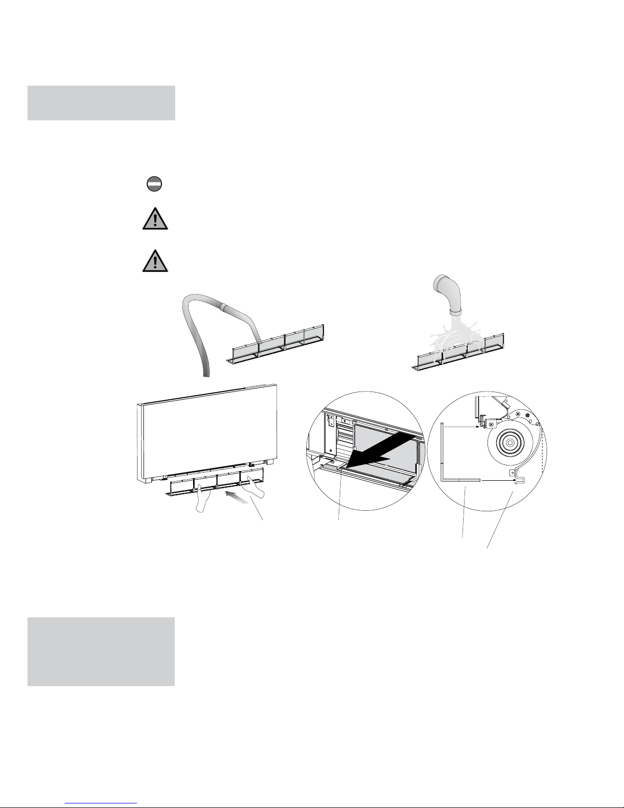
10 CZYSZCZENIE FILTRÓW / WSKAZÓWKI DOTYCZĄCE OSZCZĘDZANIA ENERGII
A filtr
B dolna krawędź
C obudowa filtra
- usuń pył z filtra za pomocą odkurzacza
- przemyj filtr bieżącą wodą bez używania detergentów ani rozpuszczalników
i pozostaw go do wyschnięcia.
- wymień filtr na klimakonwektorze, pilnując aby wsunąć jego dolną krawędź
do obudowy.
Nie korzystaj z urządzenia bez założonego filtra siatkowego.
Urządzenie wyposażone jest w wyłącznik bezpieczeństwa, zabezpieczający
przed pracą wentylatora przy odmontowanym panelu.
Po oczyszczeniu filtra upewnij się, że panel jest odpowiednio zamontowany.
CZYSZCZENIE
FILTRÓW
- dbaj o to, aby filtry były zawsze czyste;
- o ile to możliwe, pilnuj, aby drzwi i okna w klimatyzowanym pomieszczeniu
były zamknięte;
- latem chroń pomieszczenia klimatyzowane przed bezpośrednim działaniem
promieni słonecznych (używaj zasłon, żaluzji itp.)
WSKAZÓWKI
DOTYCZĄCE
OSZCZĘDZANIA
ENERGII
A
B
B
C
Page 77
NL
FR
DE
EN
IT
PL
3 PROBLEMÓW
WYKRYWANIE
W przypadku wycieku wody lub nieprawidłowego działania urządzenia należy
natychmiast odłączyć zasilanie i zamknąć wszystkie zawory wody.
W przypadku pojawienia się jednej z niżej wymienionych nieprawidłowości
należy skontaktować się z autoryzowanym centrum serwisowym lub
wykwalifikowanym personelem. Nie wolno naprawiać urządzenia samodzielnie.
- Nawiew nie uruchamia się, pomimo że w obwodzie jest ciepła lub zimna
woda.
- W czasie grzania z urządzenia wycieka woda.
- Woda wycieka z urządzenia wyłącznie w czasie chłodzenia.
- Urządzenie wydaje zbyt duży hałas.
- Na płycie przedniej powstaje rdza.
WYKRYWANIE PROBLEMÓW 11
Page 78
12 SCHEMAT PROBLEMÓW I SPOSOBÓW ICH ROZWIĄZANIA
PROBLEM PRZYCZYNA SPOSÓB ROZWIĄZANIA
Zawór przepływu potrzebuje więcej
czasu, aby się otworzyć, w wyniku
czego ciepła lub zimna woda przepływa przez urządzenie wolniej.
Odczekaj 2-3 minuty, a następnie
otwórz zawór przepływu.
Opóźniona aktywacja wentylatora
spowodowana zmianą ustawień
temperatury lub funkcji.
SCHEMAT PROBLEMÓW
I SPOSOBÓW ICH
ROZWIĄZANIA
Brak ciepłej lub zimnej wody w
instalacji.
Zawór hydrauliczny pozostaje
zamknięty.
Upewnij się, że urządzenie
grzewcze i chłodzące działają
prawidłowo.
Odmontuj obudowę zaworu i
sprawdź, czy obieg wody został
przywrócony.
Funkcja nawiewu nie aktywuje się.
Nawiew nie uruchamia się, pomimo że ciepła lub zimna woda jest
w obiegu hydraulicznym.
Silnik wentylatora jest zablokowany lub przepalił się
Sprawdź uzwojenie silnika i
upewnij się, że wiatrak obraca się
swobodnie.
Mikroprzełącznik zatrzymujący nawiew kiedy kratka filtra jest otwarta nie zamyka się prawidłowo.
Upewnij się, że zamknięcie kratki
powoduje aktywację mikroprzełącznika.
Połączenia elektryczne nie działają
prawidłowo
Sprawdź połączenia elektryczne.
Połączenia hydrauliczne systemu
przeciekają.
Sprawdź, co przecieka, i dokręć
połączenia.
W czasie grzania z urządzenia
wycieka woda.
Wycieki z jednostki zaworu. Sprawdź stan uszczelek.
Sprawdź, czy izolacja termicznoakustyczna położona jest prawidłowo, zwracając szczególną uwagę
na przednią część żebrowanego
kon wektora.
Na panelu przednim skrapla się
woda.ę
Izolacja termiczna odchodzi od
instalacji.
Problem zniknie, kiedy wilgotność zacznie spadać. Obecność
kilku kropel wody w urządzeniu
nie oznacza nieprawidłowego
działania.
Na kratce wylotu powietrza
pojawiają się krople.
W warunkach wysokiej wilgotności (>60%) może gromadzić
się kondensat, szczególnie przy
niskich szybkościach nawiewu.
Aby sprawdzić, czy odprowadzanie działa prawidłowo, powoli wlej
butelkę wody do dolnej części
konwektora; w razie potrzeby
oczyść miskę i/lub zwiększ
nachylenie rury spustowej.
Urządzenie przecieka wyłącznie w
czasie chłodzenia.
Miska na kondensat jest
zablokowana.
Spust kondensatu nie posiada
nachylenia do odpowiedniego
odprowadzania wody.
Rury łączące i jednostka zaworu
nie są odpowiednio zaizolowane.
Sprawdź izolację rur.
Urządzenie wydaje z siebie dziwne
dźwięki.
Wentylator dotyka konstrukcji.
Wentylator nie jest odpowiednio
wyważony.
Sprawdź, czy filtry nie są zapchane,
I oczyść je w razie konieczności.
Sprawdź, czy filtry nie są
zapchane, I oczyść je w razie
konieczności.
Brak wyważenia powoduje
nadmierny poziom wibracji.
Wymień wiatrak.
Oczyść filtry.
Sprawdź poprawność działania
zaworu, zasilając go oddzielnie napięciem 230 V. Jeżeli się aktywuje,
problemem może być sterowanie
elektryczne.
Page 79
NL
FR
DE
EN
IT
PL
WARUNKI GWARANCJI / OŚWIADCZENIE PRODUCENTA 13
4 WARUNKI GWARANCJI
VASCO oświadcza niniejszym, iż udziela gwarancji na Vasco Niva FC na okres
dwóch lat od daty zakupu. Data faktury wystawionej przez firmę montażową
jest datą zakupu. Jeżeli faktura nie jest dostępna, za datę zakupu uznaje się datę
produkcji. Gwarancja obejmuje wyłącznie bezpłatną wymianę wentylatora i elektronicznej płytki drukowanej przez Vasco. Nie przewidziano dodatkowego okresu
gwarancji za czas naprawy. Gwarancja nie obejmuje:
• Kosztów montażu i demontażu
• Wad, które według nas są wynikiem niewłaściwej obsługi urządzenia,
zaniedbania lub wypadków
• Wad, które są wynikiem związanych z produktem działań stron trzecich
podejmo wanych bez naszej zgody
• Wad, które są wynikiem nieregularnych lub nieprofesjonalnie
przeprowadzonych prac konserwacyjnych
• Wad, które są wynikiem użytkowania produktu w nieodpowiednim do tego
celu ś rodowisku
Używanie produktu w wyżej wymienionych okolicznościach powoduje utratę gwarancji. Instalator powinien skontaktować się z Vasco w celu wymiany wadliwych
elementów. Instalator otrzyma numer zwrotu gwarancyjnego. Wadliwe elementy
należy wysłać do Vasco, podając numer zwrotu.
Kruishoefstraat 50 ul. Jaworzyńska 295
B-3650 Dilsen 59-220 Legnica
T. +32 (0)89 79 04 11 T +48 76 850 83 00
F. +32 (0)89 79 05 00 F +48 76 850 83 01
[email protected] [email protected]
www.vasco.eu
OŚWIADCZENIE PRODUCENTA
Deklaracja zgodności UE (dyrektywa niskonapięciowa 2006/95/WE)
Vasco, firma z siedzibą pod adresem Kruishoefstraat 50, B-3650 Dilsen w
Belgii, jest producentem opisanej w niniejszym dokumencie jednostki wentylacyjnej. Produkt posiada oznaczenie CE. Na naszą wyłączną odpowiedzialność
oświadczamy, że będąca przedmiotem niniejszego oświadczenia jednostka
Vasco D60 spełnia wymagania określone dyrektywą niskonapięciową
2006/95/WE, dyrektywą zgodności elektromagnetycznej 2004/108/WE,
dyrektywą RoHS, oraz dyrektywą 2009/125/WE.
Vasco Group nv
Dilsen, Belgia, sierpień 2017
P. Nijs, Dyrektor Generalny
Page 80

Kruishoefstraat 50
B-3650 Dilsen
T. +32 (0)89 79 04 11
F. +32 (0)89 79 05 00
[email protected]
www.vasco.eu
90.DR013038.D
 Loading...