

LOT NUMBER:
DATE PURCHASED: / /
TM
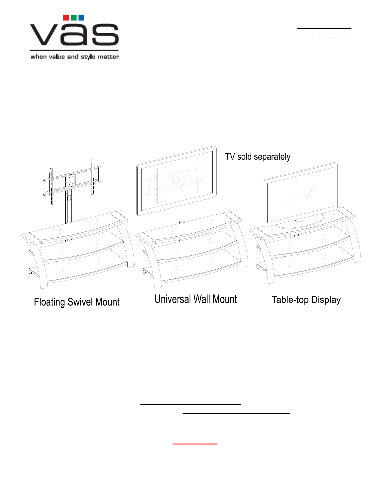
54" 3-in-1
Console
Model # XLMEC54-LR
U.S. Patents 8,079,311 & 8,191,485
This item is designed to be a 3-in-1 configuration. Please choose the option that best suits your
needs. DO NOT discard any of the hardware or parts that you will not use on your chosen option.
This will allow you to use this TV Console in different configurations at a later date, if desired.
TV
TV
ADULT ASSEMBLY REQUIRED
If you have any questions regarding assembly or if parts are missing, DO NOT return this item to the
store where it was purchased. Please call our toll-free customer service number and have your
instructions and parts list ready to provide the model name, part name or factory number:
1-866-942-5362
Pacific Standard Time: 8:30 a.m. - 4:30 p.m., Monday to Friday
Or visit our website 24 hours a day, 7 days a week for product assistance at
www.whalenfurniture.com
Or e-mail your request to parts@whalenfurniture.com
THIS INSTRUCTION BOOKLET CONTAINS IMPORTANT SAFETY INFORMATION.
PLEASE READ AND KEEP FOR FUTURE REFERENCE.
VAS® Page 1 Factory No. 10944
Date 2014-08-14 Rev. 1 Factory: FOCIDI

Model # XLMEC54-LR
MAXIMUM RECOMMENDED WEIGHT LOADS
MANUFACTURER: VAS®
CATALOG: 54" 3-in-1TM Console (XLMEC54-LR)
DATE OF MANUFACTURE: August 2014
MADE IN CHINA
FITS UP TO MOST 65” FLAT PANEL TVs
MAXIMUM LOAD 135 lb. (61.2 kg)
FITS UP TO MOST 65” FLAT PANEL TVs
WITHOUT SWIVELING BRACKET
MAXIMUM LOAD 135 lb. (61.2 kg)
MAXIMUM LOAD 50 lb. (22.6 kg)
FLAT PANEL TVS AND AUDIO/VIDEO EQUIPMENT MEETING RECOMMENDED SIZE AND
WEIGHT LIMITS. NEVER USE WITH LARGER/HEAVIER THAN RECOMMENDED FLAT PANEL
TVS OR EQUIPMENT. TO AVOID INSTABILITY, PLACE FLAT PANEL TV IN THE CENTER OF
THE UNIT; DO NOT ALLOW TV TO OVERHANG UNIT IN ANY DIMENSION. IMPROPERLY
POSITIONED FLAT PANEL TVS, OR FLAT PANEL TVS OR OTHER EQUIPMENT THAT EXCEED
RECOMMENDED SIZE AND WEIGHT LIMITS COULD FALL OFF OR BREAK THE UNIT,
CAUSING POSSIBLE SERIOUS INJURY.
THIS UNIT IS NOT INTENDED FOR USE WITH CRT TVS. USE ONLY WITH
GENERAL INFORMATION, TIPS and TRICKS
1. Please read the Assembly Instructions prior to assembling this product.
2. Remove all hardware from the box and sort by size.
3. Check to see that all hardware and parts are present BEFORE assembling.
4. Ask a friend to assist you with the assembly of this furniture.
5. To avoid damage, assemble the product on a sturdy, level and protective surface.
6. Please wait until all steps are completed before fully tightening bolts.
7. Make sure all bolts are tightly fastened before the unit is used.
This product is sold with one set of Tipping Restraint Hardware Kit. You must install the Tipping
Restraint Hardware between the wall and the TV console to prevent any accidents or
damages. When properly installed, this restraint can provide protection against the unexpected
tipping of the unit due to small tremors, bumps or climbing. The restraint is only a deterrent and
is not a substitute for proper adult supervision. Use of tip-over restraints may only reduce, but
not eliminate, the risk of tip-over.
Please call for replacement parts or assistance: 1-866-942-5362
VAS® Page 2 Factory No. 10944

Model # XLMEC54-LR
Parts and Hardware List
Please read completely through the instructions and verify that all listed parts and hardware
are present before beginning assembly.
A- Top Shelf Frame (1) B- Middle Shelf Frame (1) C- Bottom Shelf Frame (1)
D- Long Spine (1) D1- Short Spine (1)
E- Left Leg (1) F- Right Leg (1) G- Top Glass (1)
H- Middle Glass Shelf (1) I- Bottom Glass Shelf (1) J- Swiveling Bracket (1)
(Pre-attached on the Spine)
K- Mounting Frame (1) L- Monitor Bracket (2) M- Cable Wheel (2)
Please call for replacement parts or assistance: 1-866-942-5362
VAS® Page 3 Factory No. 10944

Model # XLMEC54-LR
Parts and Hardware List
Please read completely through the instructions and verify that all listed parts and hardware
are present before beginning assembly.
(1) Suction Cup (2) 1/2” Bolt (3) 3/4” Bolt (4) 1-1/4” Bolt (5) Lock Washer
(24+1 extra) (4+1 extra) (12+1 extra) (8+1 extra) (20+1 extra)
(6) Flat Washer (7) Concrete Anchor (8) 2-1/2” Lag Bolt (9) Large Flat Washer
(20+1 extra) (4) (4) (4+1 extra)
4 mm Allen Wrench Touch-up Pen Tipping Restraint Hardware Kit (1)
(2) (1) (Inside Plastic Bag)
TV Mounting Kit
M4 x 12 Bolt (4) M4 x 30 Bolt (4) M5 x 12 Bolt (4) M5 x 30 Bolt (4)
M6 x 12 Bolt (4) M6 x 35 Bolt (4) M8 x 16 Bolt (4) M8 x 40 Bolt (4)
M4 Lock Washer (4) M5 Lock Washer (4) M6 Lock Washer (4) M8 Lock Washer (4)
Large Spacer (4) Small Spacer (4) M4/M5 Flat Washer (8) M6/M8 Flat Washer (4)
Tools required: Allen wrench (provided) and Phillips screwdriver (not provided).
Please call for replacement parts or assistance: 1-866-942-5362
VAS® Page 4 Factory No. 10944
Model # XLMEC54-LR
Assembly Instructions
4
5
B/C
6
3
5
6
A
D/D1
6
5
3
C
B
D/D1
A
C
B
A
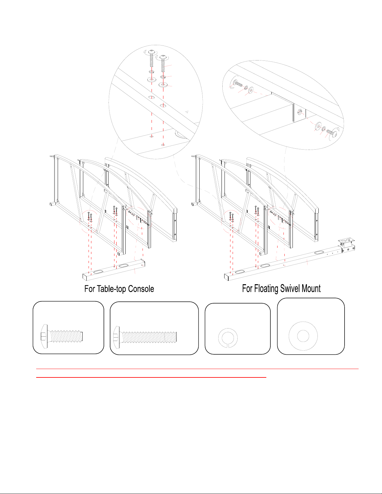
1. Unpack the unit and confirm that you have all the hardware and required parts.
2. Choose the option suits your needs. For the Floating Swivel Mount option, select the Long
3. Align and attach 3 Shelf Frames (A, B and C) to the Spine as shown. Make sure the inside
3/4” Bolt
(2 used in this step)
③
NOTE: Please do not fully tighten all bolts until you finish assembling all parts. Once assembled,
go back and fully tighten all bolts. This will make the assembly easier.
Spine (D). For the other two options, select the Short Spine (D1). Set the Spine back face down
on a scratch free surface, as shown.
corner plates on the shelf frames will face up when the unit is turned upright.
D1
1-1/4” Bolt
(4 used in this step)
④
Lock Washer
(6 used in this step)
(6 used in this step)
⑤
D
Flat Washer
⑥
Please call for replacement parts or assistance: 1-866-942-5362
VAS® Page 5 Factory No. 10944

Model # XLMEC54-LR
Assembly Instructions
F
B
E/F
6
5
3
E/F
C
6
5
3
3/4” Bolt
(6 used in this step)
③
4. Stand the unit upright.
5. Align and attach the Left Leg (E) to the Top Shelf Frame (A) by inserting two 1-1/4” Bolts (4)
with the Washers (5 and 6) from inside the Shelf Frame through the pre-drilled holes on the
side rail and screw into the threaded inserts on the Leg. Make sure that the top rail of Leg is
flush with the wooden front rail of Top Shelf Frame (A). DO NOT tighten the bolts.
6. Secure the Left Leg (E) to the Lower Shelf Frames (B and C) using the 3/4” Bolts (3) with the
Washers (5 and 6) through the end bracket holes and screw into the Leg.
7. Repeat last two steps with the Right Leg (F). Make sure that the gaps between the wooden
front rail of Top Shelf Frame and Legs are equal. Loosen the bolts on the wooden front rail
and adjust, if necessary.
A
B
D1
C
F
1-1/4” Bolt
(4 used in this step)
④
E
5
4
D
A
B
C
Lock Washer
(10 used in this step)
⑤
E/F
A
6
E
Flat Washer
(10 used in this step)
⑥
Please call for replacement parts or assistance: 1-866-942-5362
VAS® Page 6 Factory No. 10944
 Loading...