


LOT NUMBER:
DATE PURCHASED: / /
XL50-4MC
50" 3-in-1 Console (XL50-4MC)
This item is designed to be a 3-in-1 configuration. Please choose which of the 3 options suits your
needs. DO NOT discard any of the hardware or parts that you will not use on your set option, this
will give you the opportunity to use this TV Console for different configurations in case you decide
to upgrade your TV set in the future.
ADULT ASSEMBLY REQUIRED
If you have any questions regarding assembly or if you are missing parts, do not return this item to
the Retailer Store. Please call our toll free customer service number and have your instructions
and parts list ready to provide the model name, part name or factory number:
1-866-942-5362 8:30 a.m. - 4:30 p.m. PST, Monday - Friday
ONLINE: www.whalenfurniture.com EMAIL: parts@whalenfurniture.com
Video Instruction Guides
Go to http://whalen.showuhow.com to view step-by-step instructional
videos for assembling and installing your product. Enter the following
product number on the ShowUhow homepage.
THIS INSTRUCTION BOOKLET CONTAINS IMPORTANT SAFETY INFORMATION.
PLEASE READ AND KEEP FOR FUTURE REFERENCE.
VAS Furniture Mfg. Inc. Page 1 Factory No. 56-12089

MAXIMUM RECOMMENDED WEIGHT LOADS
GENERAL INFORMATION, TIPS & TRICKS
This product is sold with Tip Restraint Hardware kit. You must install the Tipping Restraint
Hardware between the wall and the TV stand to prevent any accidents or damages. When
properly installed, this restraint can provide protection against the unexpected tipping of the
unit due to small tremors, bumps or climbing. The restraint is only a deterrent and is not a
substitute for proper adult supervision. Use of tip-over restraints may only reduce, but not
eliminate, the risk of tip-over.
FITS UP TO MOST 56” FLAT PANEL TVs
MAXIMUM LOAD 135 lb. (61.2 kg)
FITS UP TO MOST 56” FLAT PANEL TVs
WITHOUT SWIVELING BRACKET
MAXIMUM LOAD 135 lb. (61.2 kg)
MAXIMUM LOAD 50 lb. (22.7 kg)
THIS UNIT IS NOT INTENDED FOR USE WITH CRT TVS. USE ONLY WITH
FLAT PANEL TVS AND AUDIO / VIDEO EQUIPMENT MEETING RECOMMENDED SIZE /
WEIGHT LIMITS. NEVER USE WITH LARGER/HEAVIER FLAT PANEL TVS OR EQUIPMENT
THAN RECOMMENDED. TO AVOID INSTABILITY, PLACE FLAT PANEL TV IN CENTER OF
UNITAND BEHIND STOPPER; DO NOT ALLOW TV TO OVERHANG UNIT IN ANY DIMENSION.
CRT TVS, IMPROPERLY POSITIONED FLAT PANEL TVS, OR FLAT PANEL TVS OR OTHER
EQUIPMENT THAT EXCEED RECOMMENDED SIZE AND WEIGHT LIMITS COULD FALL OFF
OR BREAK THE UNIT, CAUSING POSSIBLE SERIOUS INJURY.
MANUFACTURER: VAS FURNITURE
CATALOG: 50" 3-IN-1 CONSOLE (XL50-4MC)
DATE OF MANUFACTURE: APRIL, 2011
MADE IN CHINA
Model # XL50-4MC
1. Please read the Assembly Instructions prior to assembling this product.
2. Remove all hardware from box and sort by size.
3. Check to see that all hardware and parts are present BEFORE assembling.
4. Ask a friend to assist you with the assembly of this furniture.
5. To avoid damage, assemble the product on a sturdy, level and protective surface.
6. Please wait until all steps are completed before tightening bolts.
7. Make sure all bolts are tightly fastened before the unit is used.
Please call for replacement parts or assistance: 1-866-942-5362
VAS Furniture Mfg. Inc. Page 2 Factory No. 56-12089

Model # XL50-4MC
Parts and Hardware List
Please read completely through the instructions and verify that all parts listed are present
before beginning assembly.
A-Top Shelf Frame (1) B- Middle Shelf Frame (1)
C- Bottom Shelf Frame (1) D- Long Spine (1)
D1- Short Spine (1) E- Left Leg (1) F- Right Leg (1)
G- Front Left Support H- Front Right Support I- Back Left Support J- Back Right Support
(1) (1) (1) (1)
K- Top Glass (1) L- Glass Shelf (2) M- Safety Bar (1)
N- Swiveling Bracket (1) O- XYZ Mounting Frame (1) P- Monitor Bracket (2)
Please call for replacement parts or assistance: 1-866-942-5362
VAS Furniture Mfg. Inc. Page 3 Factory No. 56-12089

Model # XL50-4MC
Parts and Hardware List
(1) Suction Cup (2) 3/4” Bolt (3) 1-1/4” Bolt
(23+1 extra) (36+1 extra) (8+1 extra)
(4) Hex Nut (5) Lock Washer (6) Flat Washer
(4+1 extra) (44+2 extra) (48+2 extra)
(7) Large Flat Washer (6) (8) 2-1/2” Lag Bolt (6) (9) Concrete Anchor (6)
Open Wrench Touch-up Pen Allen Wrench Tipping Restraint Hardware Kit
(1) (1) (2) (Inside Plastic Bag)
TV Mounting Kit
M4 x 12 Bolt (4) M4 x 30 Bolt (4) M5 x 12 Bolt (4) M5 x 30 Bolt (4)
M6 x12 Bolt (4) M6 x 35 Bolt (4) M8 x 16 Bolt (4) M8 x 40 Bolt (4)
M4 Lock Washer (4) M5 Lock Washer (4) M6 Lock Washer (4) M8 Lock Washer (4)
Large Spacer (4) Small Spacer (4) M4/M5 Flat Washer (8) M6/M8 Flat Washer (4)
Tools required: Allen Wrench (provided), Open Wrench (provided) and Phillips Screwdriver.
Please call for replacement parts or assistance: 1-866-942-5362
VAS Furniture Mfg. Inc. Page 4 Factory No. 56-12089

Model # XL50-4MC
Required hardware in this step
Description (2) 3/4” Bolt (5) Lock Washer (6) Flat Washer
Sketch
Qty. (10 pcs) (10 pcs) (10 pcs)
Tools required: Allen Wrench
Assembly Instructions
Note: Please do not fully tighten all bolts until you finish assembling all parts. Once assembled,
go back and fully tighten all bolts. This will make it easier during assembly of unit.
1. Choose the option suits your needs. Locate Long Spine (D) or Short Spine (D1) on a scratch
free surface with 2 round holes facing up as shown in detail #1.
2. Align the “U” shape bracket holes of three Shelf Frames (A, B & C) with the threaded inserts
on the Spine (D or D1) respectively. Make sure the protruding portion will face floor after
assembly and the metal tabs on Middle Shelf Frame (B) up. Insert and screw 3/4” Bolts (2)
Please call for replacement parts or assistance: 1-866-942-5362
VAS Furniture Mfg. Inc. Page 5 Factory No. 56-12089
with Washers (5 & 6) through the bracket holes into the Spine. See detail #1.

Model # XL50-4MC
Required hardware in this step
Description (2) 3/4” Bolt (3) 1-1/4” Bolt (5) Lock Washer (6) Flat Washer
Sketch
Qty. (4 pcs) (8 pcs) (12 pcs) (12 pcs)
Tools required: Allen Wrench
Assembly Instructions
3. Pick up Right Leg (F) and align the back inserted nuts with the end bracket on Top Shelf
Frame (A) and the pre-drilled holes on lower Shelf Frame (B & C) simultaneously. Attach in
place using two 3/4” Bolts (2) with Washers (5 & 6) through the end bracket of Top Shelf
Frame and the 1 1/4” Bolts (3) with Washers (5 & 6) through the pre-drilled holes on Lower
Shelf Frame into the Leg. See detail #2. Make sure the top edge of leg is flush with Wooden
Front Rail of Top Shelf Frame. DO NOT tighten the bolts.
4. Repeat last step to install Left Leg (E) at the other end. Make sure the gaps and offsets
between the wooden front rail of Top Shelf Frame (A) and the Legs are the same. Loosen
the bolts on the end brackets and wooden front rail and adjust if necessary.
Please call for replacement parts or assistance: 1-866-942-5362
VAS Furniture Mfg. Inc. Page 6 Factory No. 56-12089

Assembly Instructions
Required hardware in this step
Description (2) 3/4” Bolt (5) Lock Washer (6) Flat Washer
Sketch
Qty. (12 pcs) (12 pcs) (12 pcs)
Tools required: Allen Wrench
5. Stand the unit upright.
6. For a stable structure, align and attach Front Left and Right Support (G & H) in place to
connect the Top Shelf Frame (A) with Left & Right Legs (E & F) using the 3/4” Bolts (2) with
Please call for replacement parts or assistance: 1-866-942-5362
VAS Furniture Mfg. Inc. Page 7 Factory No. 56-12089
Washers (5 & 6) through the end bracket holes, as shown in detail #3.
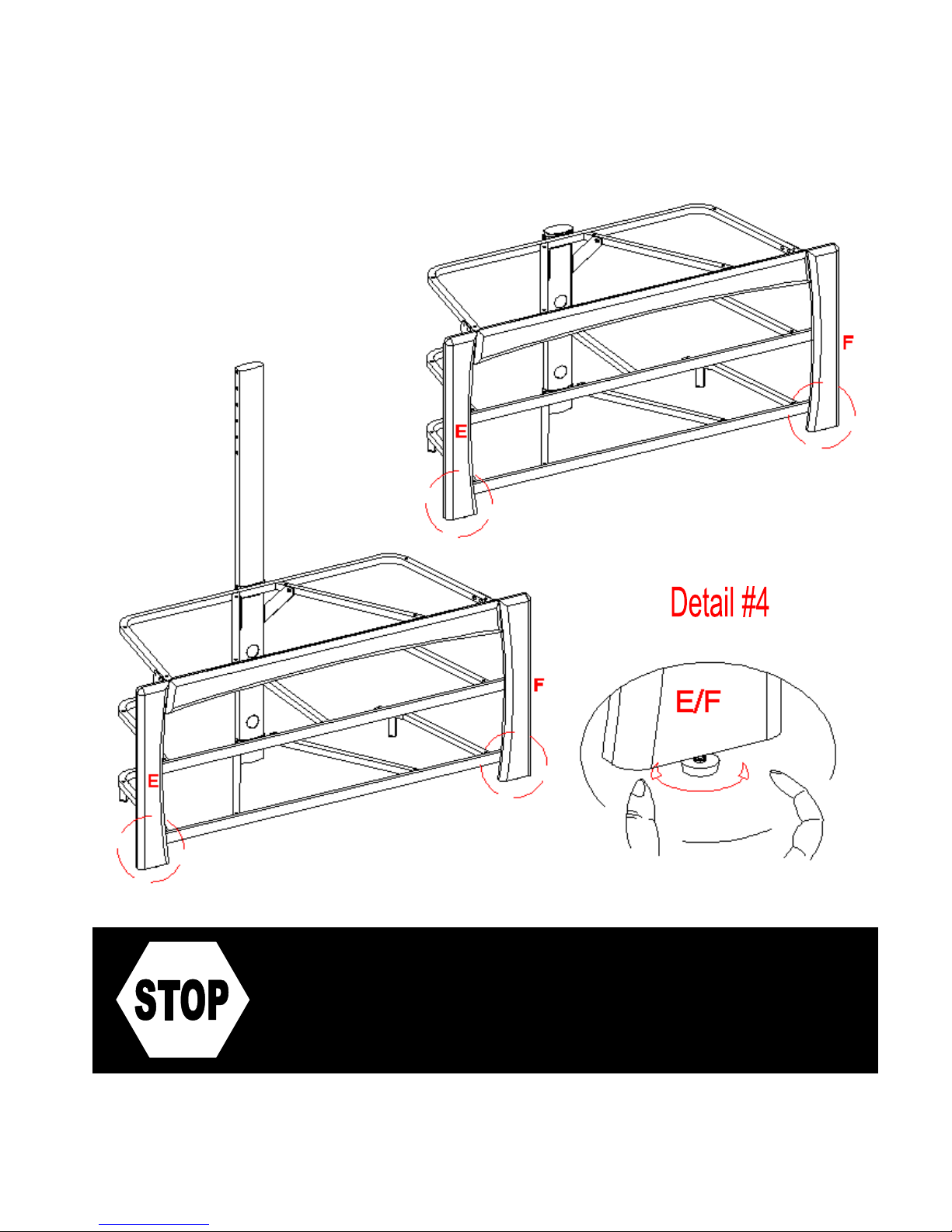
7. Align and attach the Back Left Support (I) and Back Right Support (J) to the Top Shelf
Frame (A) and Spine (D or D1) using the 3/4” Bolts (2) and Washers (5 & 6). See detail #3A.
Model # XL50-4MC
Model # XL50-4MC
If you choose Table-top configuration,
continue to STEP 9.
If mounting TV with the Swinging Floater,
skip ahead to PAGE 11.
Assembly Instructions
8. In case of uneven floor, Floor Levelers are provided at the bottom of Legs (E & F). Simply tilt
the unit back and raise or lower floor leveler by hand to correct tilting as shown in detail #4.
Please call for replacement parts or assistance: 1-866-942-5362
VAS Furniture Mfg. Inc. Page 8 Factory No. 56-12089

Assembly Instructions for Table-top
Required hardware in this step
Description Sketch Qty.
(1) Suction Cup (23 pcs)
9. Put Suction Cups (1) firmly into the top holes of 3 Shelf Frames (A, B & C) and metal tabs on
Please call for replacement parts or assistance: 1-866-942-5362
VAS Furniture Mfg. Inc. Page 9 Factory No. 56-12089
Middle Shelf Frame (B) as shown in detail #5.
10. Tilt and insert Glass Shelves (L) and Top Glass (K) in place starting with Bottom Glass Shelf
as shown in detail #5. Make sure the glass is properly centered and the black side of glass
down. Push each glass all the way back against the Spine. Also, be sure to press down
evenly and firmly each glass onto the Suction Cups to make sure they securely rest onto the
Suction Cups.
Note: Make sure that the Suction Cups go all the way into the pre-drilled holes to prevent the
glass shelf from falling and getting damage. If glass is scratched you can minimize the
damage by using a BLACK marker and filling in scratched area from underneath.
Model # XL50-4MC
Model # XL50-4MC
Assembly Instructions for Table-top
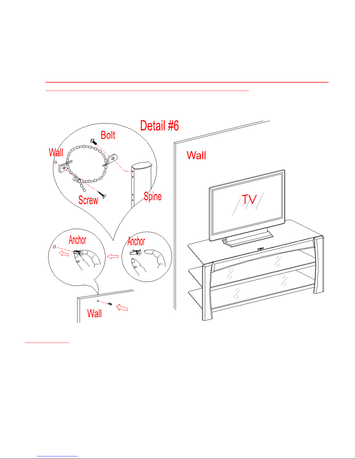
11. Position the assembled Table-top in your desired location against the wall. Now follow the
instructions printed on the plastic bag in order to mount the Tipping Restraint Hardware Kit
to the Spine properly. As shown in detail #6.
NOTE: YOU MUST USE THIS TIPPING RESTRAINT TO ATTACH THIS UNIT TO
THE WALL, TO PREVENT ACCIDENTS AND/OR INJURIES.
12. The Table-top is ready for use now if you only want to place the TV on the console top. Be
sure to position your TV in center of console with no overhang on either side.
x
Tools required: Allen Wrench (provided), Phillips Screwdriver, Mallet, Power Drill, and 3/8” Drill Bit.
Please call for replacement parts or assistance: 1-866-942-5362
VAS Furniture Mfg. Inc. Page 10 Factory No. 56-12089
Assembly Instructions for Option 1:
Console with Swinging Floater
Required hardware in this step
Description: (2) 3/4” Bolt (5) Lock Washer (6) Flat Washer
Sketch
Qty. (6 pcs) (6 pcs) (6 pcs)
Tools required: Allen Wrench
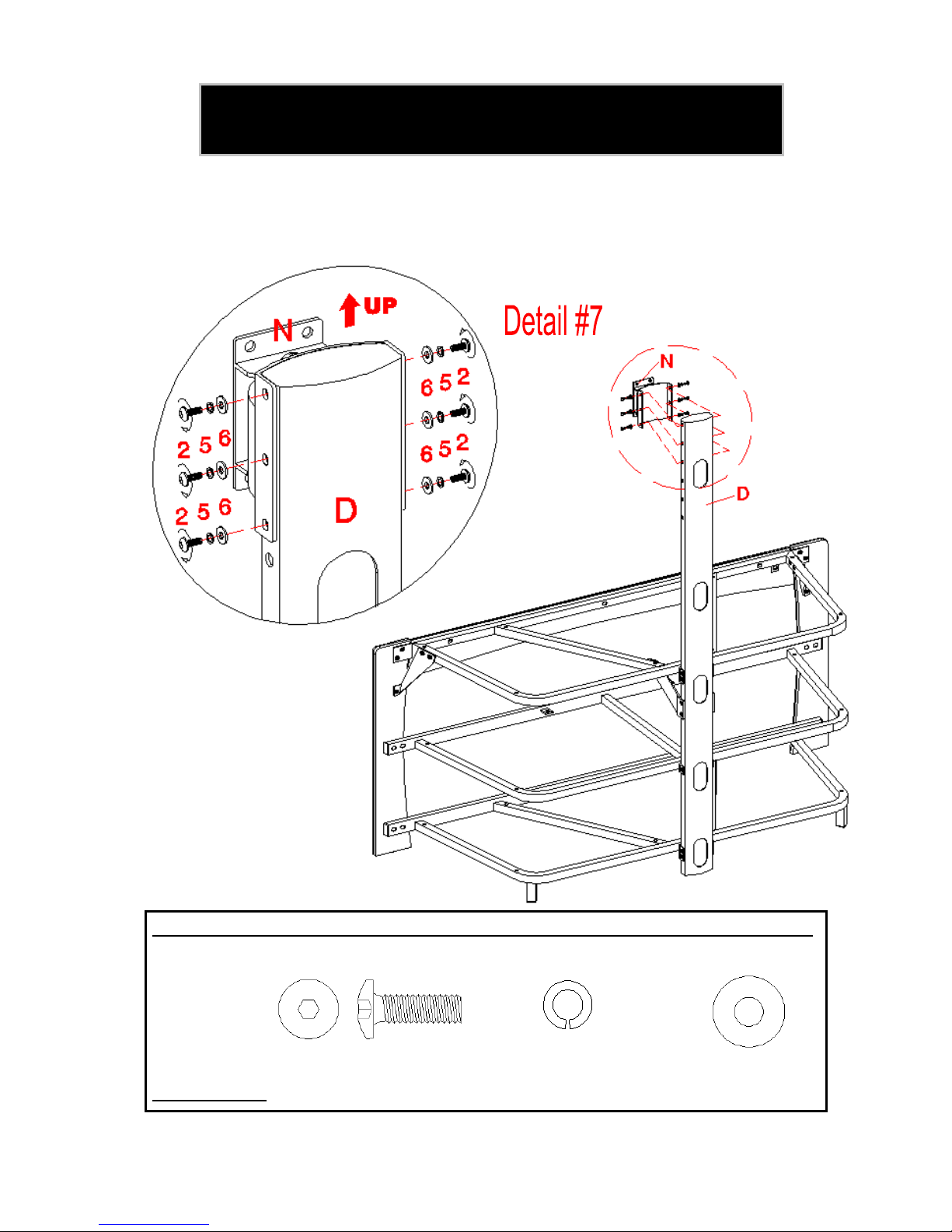
13. Align and attach Swiveling Bracket (N) to the top of Long Spine (D) using six 3/4” Bolts (2)
with Washers (5 & 6). Make sure the pivoting bolt head is up. See detail #7.
Note: The Spine can provide four height options for your TV set. Refer to your TV size, adjust the
Swiveling Bracket at your desired height to offer optimum viewing.
Please call for replacement parts or assistance: 1-866-942-5362
VAS Furniture Mfg. Inc. Page 11 Factory No. 56-12089
Model # XL50-4MC

Assembly Instructions for Option 1: Console with Swinging Floater
Required hardware in this step
Description: (2) - 3/4” Bolt (4) - Hex Nut (5) - Lock Washer (6) - Flat Washer
Sketch
Qty. (4 pcs) (4 pcs) (4 pcs) (8 pcs)
Tools required: Allen Wrench and Open Wrench
14. Hold the flat side of XYZ Mounting Frame (O) onto the Swiveling Bracket (N) ensuring the
hook on the side of Mounting Frame is bottom. Align and attach by threading four 3/4” Bolts
(2) with Flat Washers (6) through the metal plate on XYZ Mounting Frame and the Swiveling
Bracket, at the other side of Swiveling Bracket place the other Flat Washers (6) and Lock
Washers (5), and then secure with Hex Nuts (4). Securely tighten with Open Wrench and
Allen Wrench provided. See detail #8.
Please call for replacement parts or assistance: 1-866-942-5362
VAS Furniture Mfg. Inc. Page 12 Factory No. 56-12089
Model # XL50-4MC

Model # XL50-4MC
Note: For televisions with a curved back or recessed back proceed directly to step #18.
15. Determine the correct diameter of the bolt your TV requires by hand threading them into the
16. Once you have determined the correct diameter Bolt, follow the appropriate Diagram below,
17. Proceed to insert the long Bolt through the appropriate Lock Washer, the Flat Washer, the
Mounting Monitor Bracket to a television with a flat back
threaded insert on the back of the TV. If you encounter any resistance, stop immediately. If
you are unable to find the correct bolt consult a local hardware store.
thread the Short Bolt through the appropriate Lock Washer, Flat Washer, the Monitor
Bracket (P), and into the upper threaded inserts of TV. As shown in detail #9A. Note: Lean
the TV up against a wall or other solid surface when attaching with the Monitor Brackets (P).
DO NOT place the TV face down on the glass this may cause permanent damage.
slot of Monitor Bracket (P), a second Flat Washer (M4/M5 Diameter Bolts only), appropriate
Spacer, and into the bottom threaded inserts of TV. As shown in detail #9. Make sure the
Monitor Brackets (P) are centered and level with each other. Tighten the bolts securing the
Monitor Brackets to the TV.
Please call for replacement parts or assistance: 1-866-942-5362
VAS Furniture Mfg. Inc. Page 13 Factory No. 56-12089

Model # XL50-4MC
Mounting Monitor Bracket to a television with a curved / recess back
18. Determine the correct diameter of the bolt your TV requires by hand threading them into the
threaded insert on the back of the TV. If you encounter any resistance, stop immediately. If
you are unable to find the correct bolt consult a local hardware store.
19. Once you have determined the correct diameter Bolt, follow the appropriate Diagram below,
thread the Bolt through the appropriate Lock Washer, Flat Washer, the Monitor Bracket (P),
a second Flat Washer (M4/M5 Diameter Bolts only), appropriate Spacer and into the
threaded inserts of TV. See detail #10.
20. Make sure the Monitor Brackets (P) are vertically centered and level with each other.
Tighten the bolts securing the Monitor Brackets to the TV.
Please call for replacement parts or assistance: 1-866-942-5362
VAS Furniture Mfg. Inc. Page 14 Factory No. 56-12089
Model # XL50-4MC
Parts required Qty. Tools required
M– Safety Bar (1) No Tool Required
Assembly Instructions for Option 1: Console with Swinging Floater
MAKE SURE ALL BOLTS ARE TIGHT AND FLOATER POST IS AT A 90 DEGREE ANGLE
AND USING A QUALITY LEVEL TO VERIFY THE MOUNTING FRAME IS LEVEL PRIOR
TO INSTALLATION OF TV.
21. Once the Monitor Brackets (P) are attached onto the back of television, ask for assistance to
lift the television up to the XYZ Mounting Frame (O). Place the hooks on Monitor Brackets
over the Mounting Frame then lower them onto the bars of Mounting Frame. Proceed to
center the television.
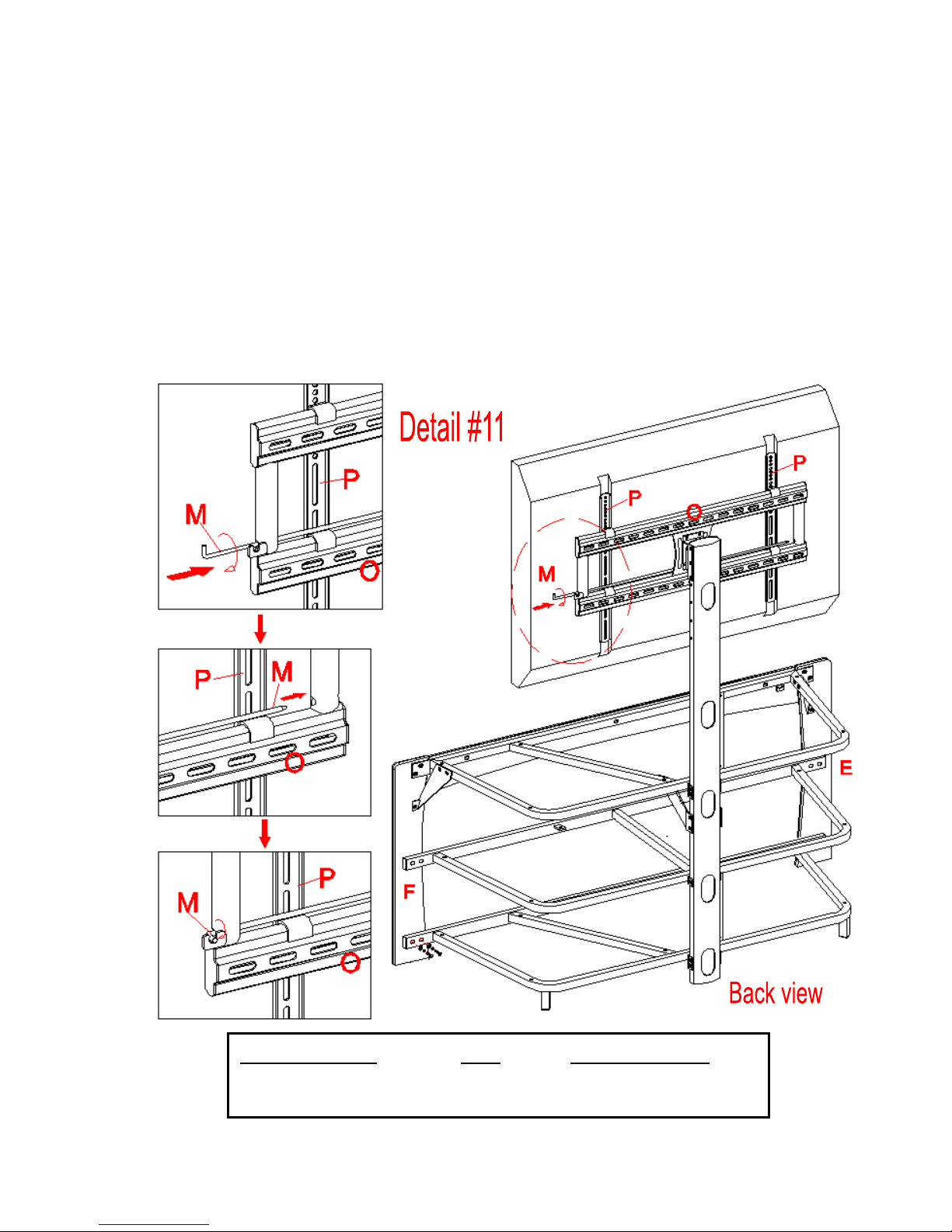
22. Insert the Safety Bar (M) into the bottom holes on the side of XYZ Mounting Frame (O) by
sliding it all the way across the frame. Secure the Safety Bar by rotating the bent end into
the slot of hook so that it is facing back of unit. Make sure it sits over the bottom hook of the
Monitor Brackets. See detail #11.
Please call for replacement parts or assistance: 1-866-942-5362
VAS Furniture Mfg. Inc. Page 15 Factory No. 56-12089

Model # XL50-4MC
Assembly Instructions for Option 1: Console with Swinging Floater
23. Repeat steps 9 and 10 to install Top Glass (K) and Glass Shelves (L) in place.
24. Carefully move the console and position in your desired location against the wall. Now follow
the instructions printed on the plastic bag in order to mount the Tipping Restraint Hardware
Kit to the Spine properly. As shown in detail #12.
Note: You must install the Tipping Restraint Hardware with the unit in use to
prevent any accidents or damage to the unit.
25. You can enjoy your home entertainment center now. Swivel left-or-right for optimum viewing
control.
Tools required: Allen Wrench (provided), Phillips Screwdriver, Mallet, Power Drill, and 3/8” Drill Bit.
Please call for replacement parts or assistance: 1-866-942-5362
VAS Furniture Mfg. Inc. Page 16 Factory No. 56-12089

Model # XL50-4MC
Do not over tighten the Lag Bolts. Tighten Lag Bolts only until the Lag
Bolt Washer is pulled firmly against the “C” Plate of Mounting Frame. If there is a layer of
drywall or other material, this drywall or other material may not exceed 5/8 inch in
thickness. Failure to heed this caution may result property damage and/or personal injury.
The following steps are only for those who wish to mount their
TV directly to the wall. If you have already mounted your TV to
the Swinging Floater or plan to display your TV on the top
surface of the stand, disregard the following steps.
Hardware provided Sketch Qty.
(7) Large Flat Washer (4)
(8) 2-1/2” Lag Bolt (4)
Tools required
Stud Sensor, Mallet, Power Drill, 3/16” Drill Bit, Socket Set
Installing XYZ Mounting Frame onto WOODEN STUD WALL
26. The XYZ Mounting Frame (O) must be mounted to two Wood Studs at least 12” apart, using
a high quality Stud Finder to locate the two adjacent studs. After you have located the studs,
verify with a nail for added security. See detail #13A.
27. Pre-drill a 2 1/2" deep hole at the desired height in each stud using a 3/16” drill bit, make
sure that the holes are centered in the studs and level with each other. Use the XYZ
Mounting Frame (O) as a template to mark the corresponding location for the bottom holes
in each stud, drill holes 2 1/2" deep with the 3/16” drill bit at the marked location.
28. Orient the Mounting Frame with the “C” plate against the wall, and using four Lag Bolts (8)
with Large Flat Washer (7) through the slots of “C” Plate on Mounting Frame into the holes
in the wall, secure the mounting frame to the wall as shown in detail #13B.
Please call for replacement parts or assistance: 1-866-942-5362
VAS Furniture Mfg. Inc. Page 17 Factory No. 56-12089
Assembly Instructions for Universal Wall Mount
Model # XL50-4MC
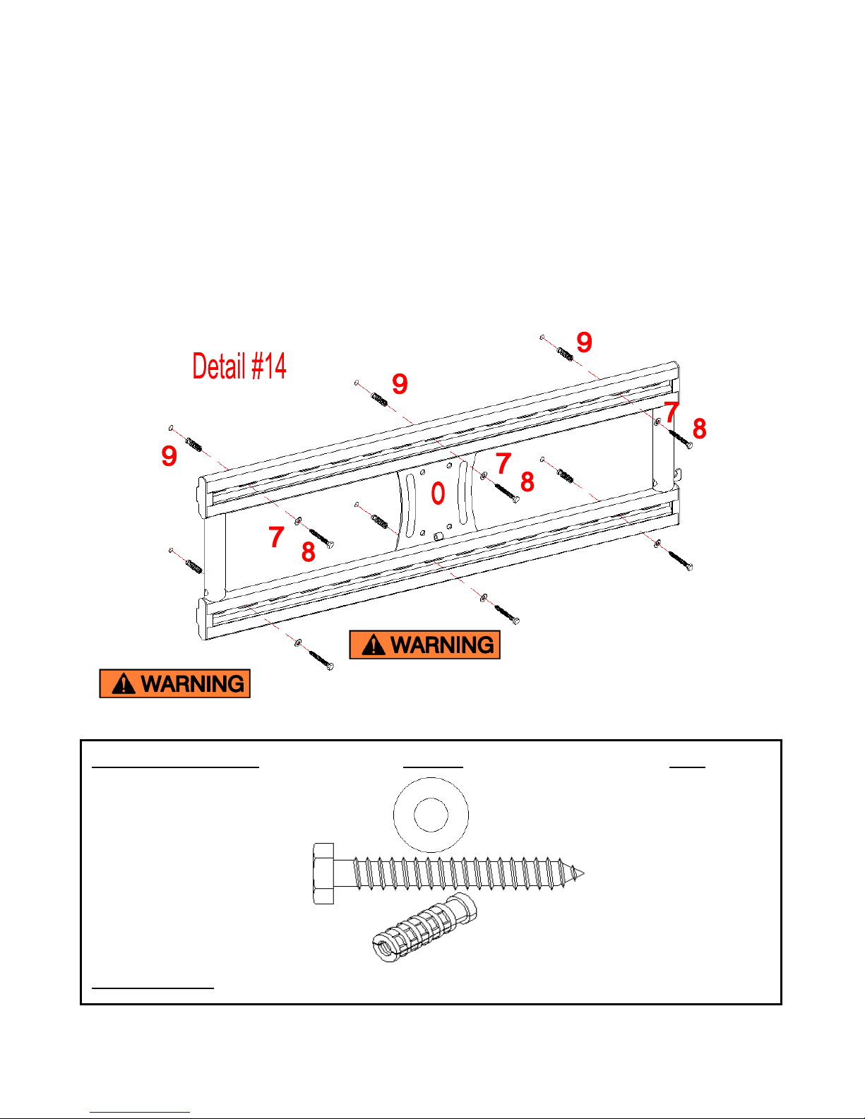
Concrete Anchors should only be used for masonry mounting.
NEVER use the wall anchors to mount the unit to drywall.
Maximum weight 165 lb. (74.8 kg)
Hardware provided Sketch Qty.
(7) Large Flat Washer (6)
(8) 2-1/2” Lag Bolt (6)
(9) Concrete Anchor (6)
Tools required: Mallet, Power Drill, 1/2” Masonry Bit for brick concrete, Socket Set and level.
Assembly Instruction for installing XYZ Mounting Frame onto BRICK, SOLID
CONCRETE OR CONCRETE BLOCK
29. Use the XYZ Mounting Frame (O) as a template, mark six holes location on the wall, three in
the top row and three in the bottom row of slots. Make sure that the holes are level and
there is at least 6” between any two holes, pre-drill these holes with a 1/2” masonry bit to at
least 2 1/2” in depth.
30. Insert a Concrete Anchor (9) into each of these holes; make sure they are completely
seated and flush with the concrete surface, even if there is a layer of drywall or other
material in front of the concrete.
31. Attach the XYZ Mounting Frame (O) to the wall using six Lag Bolts (8) and Large Flat
Washers (7) through the slot of “C” Plate on Mounting Frame into the Concrete Anchor in
the wall as shown in detail #14. Make sure the back hook of Mount Frame is bottom.
Please call for replacement parts or assistance: 1-866-942-5362
VAS Furniture Mfg. Inc. Page 18 Factory No. 56-12089

Model # XL50-4MC
Assembly Instructions
32. Once the Monitor Brackets (P) are attached onto the back of television, ask for assistance to
lift the television up to the XYZ Mounting Frame (O). Place the hooks on Monitor Brackets
over the Mounting Frame then lower them onto the bars of Mounting Frame. Proceed to
center the television.
33. Insert the Safety Bar (M) into the bottom holes on the side of XYZ Mounting Frame (O) by
sliding it all the way across the frame. Secure the Safety Bar by rotating the bent end into
the slot of hook so that it is facing wall. Make sure it sits over the bottom hook of the Monitor
Brackets. See detail #15.
34. Place assembled console under your TV set as shown in detail #15A.
Please call for replacement parts or assistance: 1-866-942-5362
VAS Furniture Mfg. Inc. Page 19 Factory No. 56-12089

Model # XL50-4MC
Care and Maintenance
Use a soft, clean cloth that will not scratch the surface when dusting.
Use of furniture polish is not necessary. Should you choose to use polish, test in an
inconspicuous area first.
Using solvents of any kind on your furniture may damage the finish.
Never use water to clean your furniture as it may cause damage to the finish.
Always use coasters under beverage glasses and flowerpots.
Liquid spills should be removed immediately. Using a soft clean cloth, blot the spill gently.
Avoid rubbing.
Always use protective pads under hot dishes and plates. Heat can cause chemical changes
that may create spotting within the furniture finish.
Stains or marks from crayons or ink markers will be difficult to remove.
In the event that your furniture is stained or otherwise damaged during use, we recommend
that you call a professional to repair your furniture.
Check bolts/screws periodically and tighten them if necessary.
Further advice about furniture care
It is best to keep your furniture in a climate-controlled environment. Extreme temperature and
humidity changes can cause fading, warping, shrinking and splitting of wood. It is advised to keep
furniture away from direct sunlight as sun may damage the finish.
Proper care and cleaning at home will extend the life of your purchase. Follow these important and
helpful tips that will enhance your furniture as it ages.
We hope you enjoy your purchase for many years.
Thank you for your purchase.
QUALITY GUARANTEE
We are confident that you will be delighted with your VAS Furniture purchase.
Should this product be defective in workmanship or materials or fail under normal use, we
will repair or replace it for up to one (1) year from the date of purchase. Every VAS
Furniture product is designed to meet your highest expectations. We guarantee that you
will immediately see the value of our fine furniture.
This warranty gives you specific legal rights and you may also have other rights which vary
from State to State (province to province).
Please call for replacement parts or assistance: 1-866-942-5362
VAS Furniture Mfg. Inc. Page 20 Factory No. 56-12089
Customer Service: 1-866-942-5362
8:30 a.m. - 4:30 p.m. PST, Monday to Friday
www.whalenfurniture.com

IF YOU NEED TO ORDER PARTS PLEASE USE THE LIST BELOW
50" 3 in 1 TV Console (XL50-4MC)
*XL50-4MC-1-LS Long Spine *XL50-4MC-14-BLS Back Left Support
*XL50-4MC-2-SS Sport Spine *XL50-4MC-15-BRS Back Right Support
*XL50-4MC-3-TSF Top Shelf Frame *XL50-4MC-16-SB Swiveling Bracket
*XL50-4MC-4-WFR Wooden Front Rail *XL50-4MC-17-MF XYZ Mounting Frame
*XL50-4MC-5-MSF Middle Shelf Frame *XL50-4MC-18-PC Plastic Cover
*XL50-4MC-6-BSF Bottom Shelf Frame *XL50-4MC-19-MB Monitor Bracket
*XL50-4MC-7-PEC Plastic End Cap (18 x 18) *XL50-4MC-20-SB Safety Bar
*XL50-4MC-8-TG Top Glass *XL50-4MC-21-FL Floor Leveler
*XL50-4MC-9-GS Glass Shelf *XL50-4MC-22-RPG Round Plastic Grommet
*XL50-4MC-10-LL Left Leg *XL50-4MC-23-OPG Oval Plastic Grommet
*XL50-4MC-11-RL Right Leg *XL50-4MC-24-CH
Complete Hardware
*XL50-4MC-12-FLS Front Left Support *XL50-4MC-25-TVMK
TV Mounting Kit
*XL50-4MC-13-FRS Front Right Support
 Loading...