

XL-1
LOT No.:
DATE OF PURCHASE:
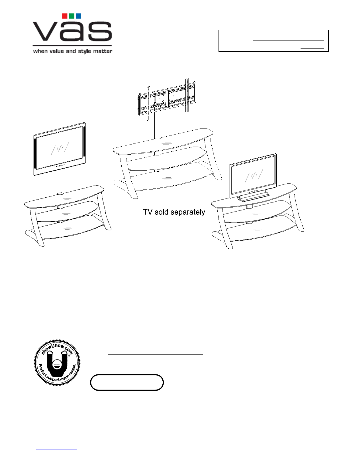
Option 1
with Swinging Floater
Option 3
Table-top
Option 2
with Universal Wall Mount
3 in 1 Flat Panel Console
Model #: XL-1
ADULT ASSEMBLY REQUIRED
If you have any questions regarding assembly or if you are missing parts, do not return this item to
the Retailer Store. Please call our toll free customer service number and have your instructions and
parts list ready to provide the model name, part name or factory number:
1-866-942-5362 8:30 a.m. - 4:30 p.m. PST, Monday - Friday
ONLINE: www.whalenfurniture.com EMAIL: parts@whalenfurniture.com
Video Instruction Guides
Go to http://whalen.showuhow.com to view step-by-step instructional videos
for assembling and installing your product. Enter the following product number
on the ShowUhow homepage.
THIS INSTRUCTION BOOKLET CONTAINS IMPORTANT SAFETY INFORMATION.
PLEASE READ AND KEEP FOR FUTURE REFERENCE.
VAS Furniture Mfg. Inc. Factory No. 55-12029 Page 1
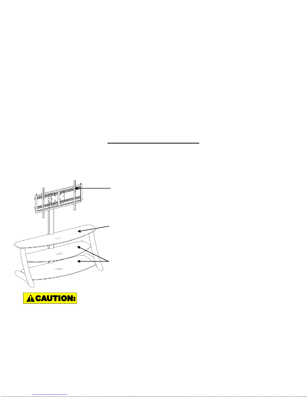
Model #: XL-1
This unit is intended for use only with the products and
maximum weights indicated. Use with other products or products heavier than
the maximum weights indicated may result in instability causing possible injury.
QUALITY GUARANTEE
We are confident that you will be delighted with your VAS Furniture purchase.
Should this product be defective in workmanship or materials or fail under
normal use, we will repair or replace it for up to 1 year from date of purchase.
Every VAS Furniture product is designed to meet your highest expectations.
We guarantee that you will immediately see the value of our fine furniture.
This warranty gives you specific legal rights and you may also have other
rights which vary from State to State.
Customer Service: 1-866-942-5362
8:30 a.m. - 4:30 p.m. PST Monday to Friday
www.whalenfurniture.com
MANUFACTURER: VAS FURNITURE
CATALOG: 3 in 1 Flat Panel Console (XL-1)
DATE OF MANUFACTURE: April, 2009
MADE IN CHINA
FITS UP TO MOST 60” FLAT PANEL TV’S
MAXIMUM LOAD 165 LBS
FITS UP TO MOST 60” FLAT PANEL TV’S WITHOUT
DELUXE BRACKET w/ MOUNTING PLATE
MAXIMUM LOAD 165 LBS
MAXIMUM SHELF LOAD 50 LBS
Notes: Flat Panel TV’s with base support should be placed squarely in the
center of the stand with no overhanging on either side.
Please call for replacement parts or assistance: 1-866-942-5362
VAS Furniture Mfg. Inc. Factory No. 55-12029 Page 2

Model #: XL-1
Parts List
Please read completely through the instructions and verify that all parts listed
are present before beginning assembly.
A-Top Frame (1) B- Shelf Frame (1)
C- Bottom Frame (1) D- Long Spine (1)
D1- Short Spine (1) EL- Left Side Leg (1) ER- Right Side Leg (1)
F- Top Glass (1) G- Middle Glass Shelf (1) H- Bottom Glass Shelf (1)
I- Deluxe Bracket w/Mounting Plate (1) J- XYZ Mounting Frame (1)
K- Monitor Bracket (2) L- Safety Bar (1)
Please call for replacement parts or assistance: 1-866-942-5362
VAS Furniture Mfg. Inc. Factory No. 55-12029 Page 3
Model #: XL-1
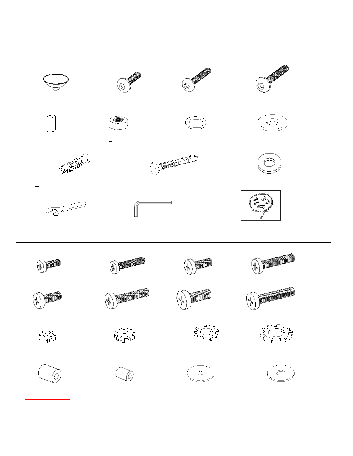
Hardware List
Please read completely through the instructions and verify that all parts listed
are present before beginning assembly.
(1)- Suction Cup (2)- 5/8” Bolt (3)- 3/4” Bolt (4)- 1 1/4” Bolt
(18+1 extra) (28+1 extra) (4+1 extra) (6+1 extra)
(5)- Stopper (6)- Nut (7)- Lock Washer (8)- Flat Washer
(2) (4+1 extra) (4+1 extra) (8+1 extra)
(9) - Concrete Anchor (6) (10) - Lag Bolt (6) (11) - Lag Bolt Washer (6)
Open Wrench (1) Allen Wrench (1) Tipping Restraint Hardware Kit (1)
(Inside Plastic White Bag)
TV Mounting Kit
M4 x 12 Bolt (4) M4 x 30 Bolt (4) M5 X 12 Bolt (4) M5 x 30 Bolt (4)
M6 x12 Bolt (4) M6 x 35 Bolt (4) M8x16 Bolt (4) M8 x40 Bolt (4)
M4 Lock Washer M5 Lock Washer M6 Lock Washer M8 Lock Washer
(4) (4) (4) (4)
Large Spacer (4) Small Spacer (4) M4/M5 Flat Washer (8) M6/M8 Flat Washer (4)
Tools Required: Allen Wrench (provided) and Open Wrench (provided), Phillips Screwdriver,
Mallet, Power Drill, 3/8” & 3/16”Drill Bit, Socket Wrench Adapter with Socket Set, 1/2”
Masonry Bit for brick concrete, Stud Sensor.
Please call for replacement parts or assistance: 1-866-942-5362
VAS Furniture Mfg. Inc. Factory No. 55-12029 Page 4
Assembly Instructions
Parts Required Qty Tools Required
A - Top Frame (1) Allen Wrench
B - Shelf Frame (1)
C - Bottom Frame (1)
D - Long Spine or D1 - Short Spine (1)
(2) - 5/8” Bolt (12)
Note: Please do not fully tighten all bolts until you finish assembling all parts, then go
back and fully tighten all bolts, this will make it easier during assembly of unit.
1. Unpack the unit and confirm that you have all the hardware and required parts listed.
Note: Please decide which configuration you would like to use before starting to assemble
the unit. Once you decide you can continue with steps #2 through #7, or skip any of the
steps you don’t need, according to your option.
Option #1 Short Spine (Steps #8 to 10) Console Only
Option #2a Long Spine (Steps #11 & 12) Swinging Mount: DLX Bracket w/Mounting Plate
Option #2b Long Spine (Steps #13 to 23) Swinging Mount: XYZ Mounting Frame
Option #3 Short Spine (Steps #24 to 35) Wall Mount
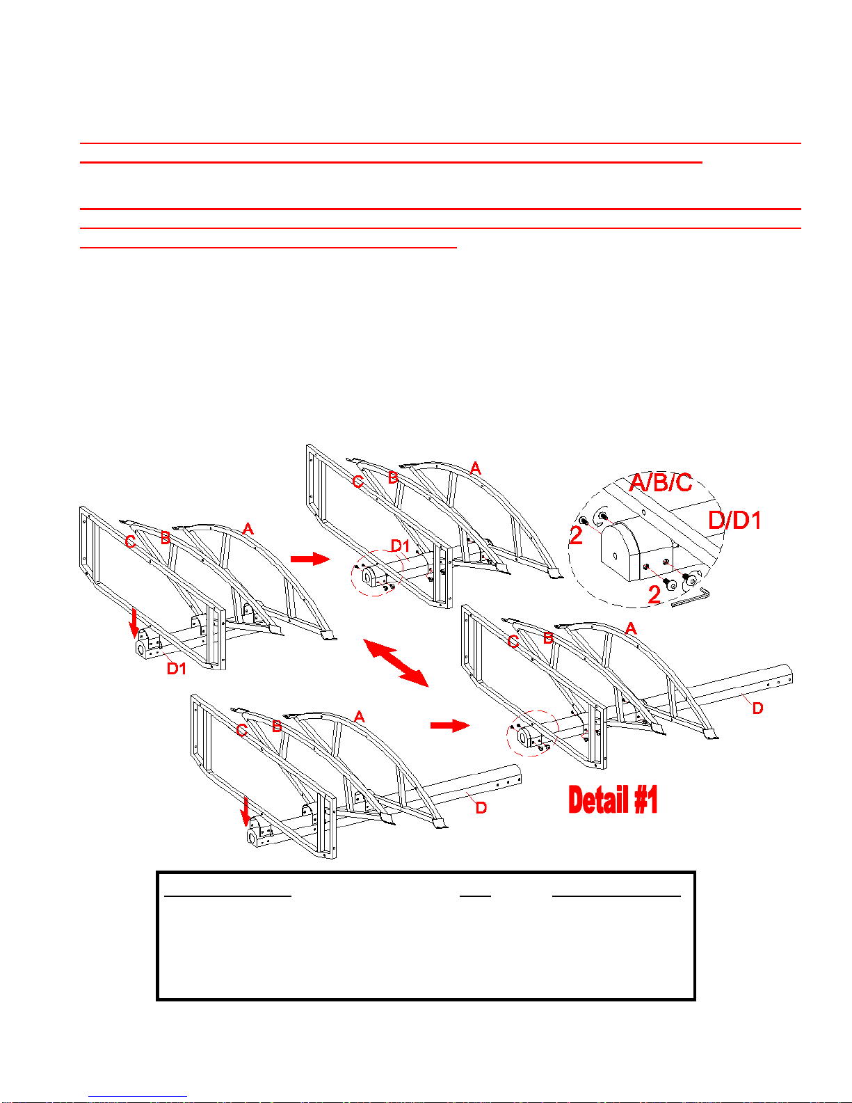
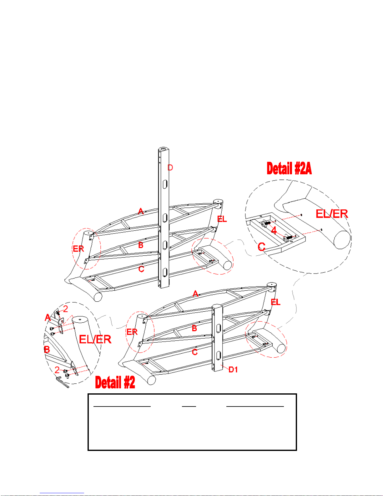
2. Locate the Spine (D) or Short Spine (D1) and set back face down on a scratch free
surface, then place the Shelf Frames (A, B & C) on it, make sure the holes of the bracket
aligned with the threaded inserts of the Spine and the top surface of Frames are flush
with the grooves of Spine. Then assemble the Shelf Frames to Spine with the 5/8” Bolts
(2). See detail #1.
Please call for replacement parts or assistance: 1-866-942-5362
VAS Furniture Mfg. Inc. Factory No. 55-12029 Page 5
Model #: XL-1
Assembly Instructions
Parts Required Qty Tools Required
EL –Left Side Leg (1) Allen Wrench
ER –Right Side Leg (1)
(2) - 5/8” Bolt (10)
(4)- 1 1/4” Bolt (4)
3. Stand the unit upright.
4. Align and attach the Side Legs (EL & ER) to Bottom Frame (C), using four 1 1/4” Bolts (4)
through the bottom frame holes from inside. As shown in detail #2A.
5. Proceed to attach the Left and Right Side Legs (EL & ER) to Top and Middle Shelf
Frames (A & B), using the 5/8” Bolts (2) through the end bracket holes into the threaded
inserts located on the Side Legs, as shown in detail #2.
6. Now fully tighten all the bolts.
Note: Ask a friend to help and make sure that the top of legs are flush with the Top
Frame (A).
Please call for replacement parts or assistance: 1-866-942-5362
VAS Furniture Mfg. Inc. Factory No. 55-12029 Page 6
Model #: XL-1

Model #: XL-1
Parts Required Tools Required
Pre-attached Floor Leveler No Tool Required
Assembly Instructions
7. In case of uneven floor, just tilt the unit back and use your hand to turn the Floor
Levelers attached on the bottom of Side Legs (EL & ER) and adjust the height of the
unit, until the unit is level. As shown in detail #3.
Please call for replacement parts or assistance: 1-866-942-5362
VAS Furniture Mfg. Inc. Factory No. 55-12029 Page 7

Option #1: CONSOLE ONLY
Parts Required Qty Tools Required
F - Top Glass (1) No Tool Required
G – Middle Glass Shelf (1)
H – Bottom Glass Shelf (1)
(1) - Suction Cup (18)
8. Now put the Suction Cups (1) into top holes of all Frames (A, B & C) and Left and Right
Side Leg (EL & ER) into place. As shown in detail #4.
9. Place the Glass Shelf (F, G & H) in place as shown in detail #4.
Note: Make sure that the Glass sits correctly and goes all the way into the grooves on the
Spine and the Suction Cups go all the way into the pre-drilled hole to prevent the glass
shelf from falling and getting damage.
Please call for replacement parts or assistance: 1-866-942-5362
VAS Furniture Mfg. Inc. Factory No. 55-12029 Page 8
Model #: XL-1

Model #: XL-1
Parts Required Tools Required
Assembled TV Stand No Tool Required
Option #1: CONSOLE ONLY
10. Position assembled TV Stand against the wall in the room you want to place your TV,
then with the help of a friend place the TV on the Top Glass (F). See detail #5.
Please call for replacement parts or assistance: 1-866-942-5362
VAS Furniture Mfg. Inc. Factory No. 55-12029 Page 9

Model #: XL-1
Parts Required Qty Tools Required
I – Deluxe Bracket w/Mounting Plate (1) Allen Wrench
(2) – 5/8” Bolt (6)
Option #2a: SWINGING MOUNT with DLX. BRACKET
11. Attach the Deluxe Bracket w/Mounting Plate (I) to the Top of Long Spine (D), using six
5/8” Bolts (2) through the bracket holes into the threaded inserts located on the side of
the Spine (D), three bolts per side. See detail #6.
Please call for replacement parts or assistance: 1-866-942-5362
VAS Furniture Mfg. Inc. Factory No. 55-12029 Page 10

Model #: XL-1
Parts Required Tools Required
See TV Mounting Kit Phillips Screwdriver
Assembly Instructions
12. You can install your Plasma / LCD TV directly, using the appropriate Bolts through the
Lock Washers and Flat Washers through the proper holes of Mounting Plate preattached on the Deluxe Bracket (I) and then into the back of the TV set. See detail #7.
Note: Hand threading the bolt in the TV Mounting Kit included into the threaded insert
on the back of the TV to determine correct size bolt you will require. If you are unable to
find the correct one, consult a local hardware store.
Please call for replacement parts or assistance: 1-866-942-5362
VAS Furniture Mfg. Inc. Factory No. 55-12029 Page 11

Parts Required Qty Tools Required
J – XYZ Mounting Frame (1) Allen Wrench
(3) – 3/4” Bolt (4) Open Wrench
(6) – Nut (4)
(7)– Lock Washer (4)
(8) – Flat Washer (8)
Option #2b: SWINGING MOUNT W/ XYZ MOUNTING FRAME
13. Do Step #11. Now attach the XYZ Mounting Frame (J) to the Deluxe Bracket w/Mounting
Plate (I), using four 3/4” Bolts (3) through the Flat Washer (8) through the holes of XYZ
Mounting Frame (J) and Mounting Plate, through the other Flat Washer (8) and Lock
Washer (7) and secure with the Nut (6). See detail #8.
Please call for replacement parts or assistance: 1-866-942-5362
VAS Furniture Mfg. Inc. Factory No. 55-12029 Page 12
Model #: XL-1

Model #: XL-1
Note: For televisions with a curved back or recessed back proceed directly to step #17.
14. Determine the correct diameter of the bolt your TV requires by hand threading them into
the threaded insert on the back of the TV. If you encounter any resistance, stop
immediately. If you are unable to find the correct bolt consult a local hardware store.
15. Once you have determined the correct diameter Bolt, follow the appropriate Diagram
below, thread the Short Bolt through the appropriate Lock Washer, the Flat Washer, the
Monitor Bracket (K), and into the upper threaded inserts of TV. As shown in detail
#9A. Note: Lean the TV up against a wall or other solid surface when attaching with the
Monitor Brackets (K). DO NOT place the TV face down on the glass this may cause
permanent damage.
16. Proceed to insert the long Bolt through the appropriate Lock Washer, the Flat Washer,
the slot of Monitor Bracket (K), a second Flat Washer (M4/M5 Diameter Bolts only),
appropriate Spacer, and into the bottom threaded inserts of TV. As shown in detail #9.
Make sure the Monitor Brackets (K) are centered and level with each other. Tighten the
bolts securing the Monitor Brackets (K) to the TV.
Mounting Monitor Bracket to a television with a flat back
Please call for replacement parts or assistance: 1-866-942-5362
VAS Furniture Mfg. Inc. Factory No. 55-12029 Page 13

Model #: XL-1
Parts Provided Qty Tools Required
K – Monitor Bracket (2) Phillips Screwdriver
TV Mounting Kit
Mounting Monitor Bracket to a television with a curved / recess back
17. Determine the correct diameter of the bolt your TV requires by hand threading them into
the threaded insert on the back of the TV. If you encounter any resistance, stop
immediately. If you are unable to find the correct bolt consult a local hardware store.
18. Once you have determined the correct diameter Bolt, follow the appropriate Diagram
below, thread the Bolt through the appropriate Lock Washer, Flat Washer, the Monitor
Bracket (K), a second Flat Washer (M4/M5 Diameter Bolts only), appropriate Spacer and
into the threaded inserts of TV. See detail #10.
19. Make sure the Monitor Brackets (K) are vertically centered and level with each other.
Tighten the bolts securing the Monitor Brackets (K) to the TV.
Please call for replacement parts or assistance: 1-866-942-5362
VAS Furniture Mfg. Inc. Factory No. 55-12029 Page 14

Assembly Instructions
Parts Required Qty Tools Required
L – Safety Bar (1) Allen Wrench
(4) – 1 1/4” Bolt (2)
(5) – Stopper (2)
20. Now you can hang your Plasma by placing the Monitor Bracket (K) over the XYZ
Mounting Frame (J). Once the TV is in place, insert the Safety Bar (L) completely into the
bottom taper holes on the XYZ Mounting Frame. Make sure that it sits over the bottom
hook of the Monitor Bracket and the bent end is faced toward wall and turned into the
slot of back hook for additional security. See detail #11.
21. Attach two Stoppers (5) with the 1 1/4” Bolt (4) at each end of the XYZ Mounting Frame (J)
to prevent the TV from falling. See detail #11.
Please call for replacement parts or assistance: 1-866-942-5362
VAS Furniture Mfg. Inc. Factory No. 55-12029 Page 15
Model #: XL-1

Assembly Instructions
Parts Required Qty Tools Required
F - Top Glass (1) No Tool Required
G – Middle Glass Shelf (1)
H – Bottom Glass Shelf (1)
(1) - Suction Cup (18)
22. Now put the Suction Cups (1) into top holes of all Frames (A, B & C) and Left & Right
Side Leg (EL & ER) into place. As shown in detail #12.
23. Place the Glass Shelf (F, G & H) in place as shown in detail #12.
Note: Make sure that the Glass sits correctly and goes all the way into the grooves on the
Spine and the Suction Cups go all the way into the pre-drilled hole to prevent the glass
shelf from falling and getting damage.
Please call for replacement parts or assistance: 1-866-942-5362
VAS Furniture Mfg. Inc. Factory No. 55-12029 Page 16
Model #: XL-1

Option #3: WALL MOUNT w/XYZ MOUNTING FRAME
Parts Required Qty
J – XYZ Mounting Frame (1)
(10) – Lag Bolt (4)
(11) – Lag Bolt Washer (4)
Tools Required
Stud Sensor, Mallet, Power Drill, 3/16” Drill Bit and Socket Wrench
Adapter with Socket Set
Maximum weight 165 lbs.
24. In case you want to hang your Plasma TV on the wall, you can follow these steps.
25. The XYZ Mounting Frame (J) must be mounted to two Wood Studs at least 12” apart,
using a high quality stud sensor locate two adjacent studs, verify with a nail if correct.
26. Pre-drill a 2 1/2" deep hole at the desired height in each stud using a 3/16” drill bit, make
sure that the holes are center area of the studs and level with each other. Use the XYZ
Mounting Frame (J) as a template to mark the location of the second hole in each stud
and drill another set of holes 2 1/2" deep with the 3/16” drill bit in the marked location.
27. Now attach the XYZ Mounting Frame to the Wall using four Lag Bolts (10) through the
Lag Bolt Washer (11) through the XYZ Mounting Frame into the holes in the wall. Make
sure the Bracket is oriented so the flat surface of the “U” plate is against the wall and
that a set of Lag Bolts is on each side of the center rail as shown in detail #13.
Please call for replacement parts or assistance: 1-866-942-5362
VAS Furniture Mfg. Inc. Factory No. 55-12029 Page 17
Model #: XL-1

XYZ MOUNTING FRAME on BRICK, SOLID CONCRETE OR BLOCK
Parts Required Qty Parts Required Qty
J – XYZ Mounting Frame (1) (9) –Concrete Anchor (6)
(10) – Lag Bolt (6) (11) – Lag Bolt Washer (6)
Tools Required
Mallet, Power Drill, 1/2” Masonry Bit and Socket Wrench Adapter with
Socket Set
Maximum weight 165 lbs.
28. Use the XYZ Mounting Frame (J) as a template to mark six holes location in the
wall, three in the top row and three in the bottom row of slots.
29. Make sure that the holes are level and there is at least 6” between any two holes,
pre-drill these holes with a 1/2” masonry bit to at least 2 1/2” in depth.
30. Now insert a Concrete Anchor (9) into each of these holes; make sure the anchor
is seated completely flush with the concrete surface even if there is a layer of
drywall of other material in front.
31. Now attach the XYZ Mounting Frame (J) to the Wall using six Lag Bolts (10)
through the Lag Bolt Washer (11) through the slot of “U” Plate on XYZ Mounting
Frame into the holes in the wall. Make sure the Bracket is oriented so the flat
surface in the center of the plate is against the wall and that a set of Lag Bolts is
on each side of the center rail as shown in detail #14, only in this case will have
three Bolts per side.
Please call for replacement parts or assistance: 1-866-942-5362
VAS Furniture Mfg. Inc. Factory No. 55-12029 Page 18
Model #: XL-1

Model #: XL-1
Parts Required Qty Tools Required
L – Safety Bar (1) Allen Wrench
(4) – 1 1/4” Bolt (2)
(5) – Stopper (2)
32. Repeat steps 14 thru 19 to mount Monitor Brackets (K) to your TV depending on the back
style of the TV.
33. Attach two Stoppers (5) at the end of the XYZ Mounting Frame (J) with 1 1/4” Bolts (4) as
shown in detail #15A. Now you can hang your TV by hooking the Monitor Brackets (K)
over the XYZ Mounting Frame.
34. Once the TV is in place, insert the Safety Bar (L) completely into the bottom taper holes
on the XYZ Mounting Frame. Make sure that it sits over the bottom hook of the Monitor
Bracket and the bent end is faced toward wall and turned into the slot of back hook for
additional security. See detail #15B.
35. Now you can place assembled Table Top under your TV set installed.
Assembly Instructions
Please call for replacement parts or assistance: 1-866-942-5362
VAS Furniture Mfg. Inc. Factory No. 55-12029 Page 19

Model #: XL-1
TIPPING RESTRAINT HARDWARE
Note: We have included one Tipping Restraint Hardware bag for this Unit.
When properly installed, this restraint can provide protection against the
unexpected tipping of the unit due to small tremors, bumps or climbing. We
strongly recommend mounting this hardware to a wall stud and your Unit when
installing.
Please carefully read the instructions printed on the bag.
Note: You must install the Tipping Restraint Hardware with the unit in use to
prevent any accidents or damage to the unit.
Tools Required: Allen Wrench (provided), Phillips Screwdriver, Mallet, Power Drill,
and 3/8” Drill Bit.
Your assembly should now be complete.
Thank you for your purchase.
Please call for replacement parts or assistance: 1-866-942-5362
VAS Furniture Mfg. Inc. Factory No. 55-12029 Page 20
 Loading...