

Page 1

Manual
Strobe Xenon 3000DMX
Page 2

Table of contents
1.
Safety instructions ............................................................................................................................ 3
1.1. Instructions for a safe and efficient operation .......................................................................... 3
1.2. Further safety instructions ....................................................................................................... 4
2. Introduction ....................................................................................................................................... 7
3. Connections ..................................................................................................................................... 7
3.1. Electrical connections .............................................................................................................. 7
3.2. DMX connections .................................................................................................................... 7
3.3. DMX connection with terminator.............................................................................................. 7
4. Bedienung ........................................................................................................................................ 8
4.1. Lamp power setting ................................................................................................................. 8
4.2. Compatible lamps .................................................................................................................... 8
4.3. DMX modes ............................................................................................................................. 8
4.4. Setting the DMX address ......................................................................................................... 8
4.5. Standalone mode .................................................................................................................. 10
5. DMX chart ...................................................................................................................................... 11
5.1. Mode 1 (1 channel) ................................................................................................................ 11
5.2. Mode 2 (3 channels) .............................................................................................................. 11
5.3. Mode 3 (4 channels) .............................................................................................................. 11
6. Replace the lamp ........................................................................................................................... 12
7. Technical data ................................................................................................................................ 13
2 / 16
Page 3

1. Safety instructions
• This Device is suitable for indoor use only.
• All modifications will void the warranty.
• Repairs have to be carried out by skilled personnel only.
• Only use fuses of the same type and original parts as spare parts.
• Protect the Unit from rain and humidity to avoid fire and electric shocks.
• Make sure to unplug the power supply before opening the housing.
1.1.
Be careful with heat and extreme temperature
Only use the device in a place where no extreme temperatures will occur.
Do not keep it in a temperature bellow 32°F /0°C, or exceeding 104°F /40°C.
Avoid exposing it to direct rays of the sun or near a heating appliance.
Keep away from humidity, water and dust
Do not place the set in a location with high humidity or lots of dust.
Containers with liquid should not be placed on the set.
Avoid placing it on un-stable location
Select a level and stable location to avoid vibration.
Do not use chemicals or volatile liquids for cleaning
Use a clean dry cloth to wipe off the dust. Metall Parts can be cleaned with a wet soft cloth for
stubborn dirt.
If out of work, contact sales agency soon
If any troubles occurs, remove the power plug immediately, and contact with an engineer for repairing,
do not open the cabinet by yourself, it might result a danger of electric shock.
Take care with the power cable
Never pull the power cable to remove the plug from the receptacle, be sure to hold the plug. When not
using the device for an extended period of time, be sure to disconnect the plug from the receptacle.
Instructions for a safe and efficient operation
IMPORTANT:
Damages caused by the disregard of this user manual are not subject to warranty. The dealer will not
accept liability for any resulting defects or problems. Make sure the electrical connection is carried out
by qualified personnel. All electrical and mechanical connections have to be carried out according to
the European safety standards.
3 / 16
Page 4

IMPORTANT
IMPORTANT!
Health risk!
before operating about the use of a stro be. Avoid longer flash sequences.
1.2. Further safe ty instructions
Keep away from water and humidity!
Make sure to unplug the power supply before opening the h ou sing!
Please read careful through this manual before the first start-up.
All persons which are entrusted with insta lla tio n, start -up, operation, maintenance and repair of this
device have to:
• Show a corresponding competence.
• Follow the lines of this manual.
• Face this manual as part of the product.
• Keep this manual over the lifetime of the product.
• Pass this manual to new owners of the device.
• Download the latest version of the manual.
Safety-related red flags
Handle carefully with dangerous electric voltages.
With this voltage there is the danger to get a life-threatening elect ric sh ock.
Always observe
After taken the device from a cold room to a warm room, it is not allowed to activate the device.
It is possible that thereby emerged condensed water damages the device. Do not Activate the device
until it reached ambient temperature.
Prevent that the power cable has contact with other cables. Handle carefully with power cables and
power connections. Don’t touch them with clammy hands.
Make sure that the connected voltage does not exceed the specified values.
Make sure that it isn’t possible to squeeze or damage the power cable with sharp edges. Assure
yourself with regular checks that there are no damages to the power cable or the device.
Don’t switch the device in short time intervals (e.g. in second cycle) on and off.
Keep away children and laymen off the device.
Don’t look directly into the light source. At certain circumstances it is
possible that some people get epileptic seizures. This is especially true for
individuals whose epilepsy was determined by a doctor. The device causes
(UV) radiation. Therefore, keep a safe distance (at least 1.5m) to people and
objects and operate it never without the protective glass on the front page!
By fast flashing, the risk of an epileptic seizure increases. Therefore do not
install it in danger zones (such as sta ir s, exit routes ...). Inform the visitors
4 / 16
Page 5

Designated use
This device was developed for professional use on stages, in discos, theatres etc. The device is only
approved for a connection up to 230V 50/60 Hz AC voltage and only for indoor use.
Regular breaks during operation increase the lifetime of your device.
Avoid convulsions or any form of forceful impact during the installation or the start-up of the device.
Make sure that the device is not exposed excessive heat, humidity or dust at the place of installa tio n.
Take care that no cables are lying around. You would endanger your own safety and also the safety of
a third party.
It is not allowed to operate or store the device in an environment in which spray water, rain, humidity
or fog is expected. Moisture or
humidity could reduce the isolation of the device and could cause
deathly electric shocks. If you use fog devices the device has not be exposed to a direct smoke jet.
There has to be a safety distance of at least 0.5m between this device and the fog machine. Make
sure that the saturation of the fog has to enable a visibility of at least 10m.
The ambient temperature has to be between 0°C and +40°C. Avoid direct sunlight and close proximity
to heaters. You have also to attend it during the transport in closed motor vehicles.
You have to attend that with an ambient temperature von 40°C it is not allowed that the relative
humidity exceeds 50%.
Do not operate the device during thunderstorms. Surge voltages could destroy the device. Unplug the
power supply during thunderstorms.
During the installation the use of the mounting bracket is obligatory.
Surrounding objects or surfaces should not be in contact with the device.
Make sure that during the installation and removal of the device the area below the place of
installation is basically cordoned off. This also applies to implementation of service.
The device has to be protected by a suitable safety-cord.
Get yourself familiar with the functions of the device before start-up. People without the experience
should not handle the device. The most cause of functional disorder is inappropriate handling.
Do not use chemicals or volatile liquids for cleaning. Use a clean dry cloth to wipe off the dust, or a
wet soft cloth for stubborn dirt.
For transport use the original packing or designated accessory to avoid damages during the transport.
For reasons of safety unauthorized changes are forbidden.
A usage of the device which differs from usages which are described in this manual can cause
damages of the device. In that case the warranty expires. Additionally you should notice that every
differed usage is related with dangers and can cause e.g. an electrical short, fire, electric shock or
crash.
5 / 16
Page 6

Danger of life!
Overhead installation
You have to observe the regulations of BGV C1 (formerly VBG 70) and
EN60598-2-17 Installations are to carry out by skilled personnel only.
The suspension devices have to be build and measured so they can withstand for an hour the tenfold
of the payload without suffering a permanent detrimental deformation.
Basically installation has to be made by using a second separate suspension. This can be e.g. a
suitable net. The second suspension has to be designed and attached so no part of the installation
can fall down in case of failure.
During construction, reconstruction and deconstruction unnecessary stay in the range of moving
areas, on lightning bridges, under elevated work stations or any other danger zones is forbidden.
The operator is obliged to following safety-related and mechanica l fac ilities:
- Before the first start-up or after critical changes bef ore restarting it has to be chec ked by an
expert.
- Review in the frame of the inspection test at least al l four years by an expert. .
- Review by a qualified person at least once a year.
How to carry out the overhead installation:
If possible you should install the device out of the areas where people could stay.
IMPORTANT! Overhead installation requires a high level of experience. This includes knowledge of
calculating the payload, used installation material and safety inspections of the used material and the
projector whereas the required experience is not limited to this. Do not try to carry out installation
yourself under any circumstances if you are not qualified. Contact a professional installer. An
inappropriate installation can lead to injuries and/or damaged properties.
It is not allowed to install the device in the grip area of people.
If the device may hang from the ceiling or from high beams, the use of truss systems is mandatory.
The device may not be installed so it can swing freely in the room.
Please note: Crashing down items can cause serious injuries! Do not install the projector, if you doubt
the safety of a possible installation form!
Before installation make sure that the mounting surface has the ability to carry the tenfold point load of
the own weight of the device.
Mount the device with the mounting-bracket to your trussing system using an appropriate clamp.
During overhead installation the device always must be secured by a safety rope which is designed to
hold the twelvefold weight of the device. Only safety ropes with quick-release safety fastener elements
may be used. Hang up the safety rope in the hole of the mounting bracket. Direct the rope over the
truss or an appropriate fastening point. Hang up the end in the fastening element and tie up the
locking nut. A safety rope once exposed to failing load or damaged may not be used furthermore.
The maximum drop distance must not exceed 20cm.
A safety rope once exposed to failing load or damaged may not be used furthermore.
Adjust the desired inclination angle via the mounting bracket and tighten the screw.
6 / 16
Page 7
Cable (EU)
Cable (US)
Pin
International
Brown
Black
Live
L
Light blue
White
Neutral
N
Yellow/Green
Green
Earth
1
2
3
P IN 3
P IN 2
120Ω
2. Introduction
Thank you for buying the Strobe Xenon 3000DMX. It is a powerful device.
For a successful installation and operation, please read this manual carefully.
3. Connections
3.1. Electrical connections
If you wish to change the power supply settings, see the chapter Appendix. Connect the fixture to the
mains with the enclosed power cable and plug. The earth has to be connected.
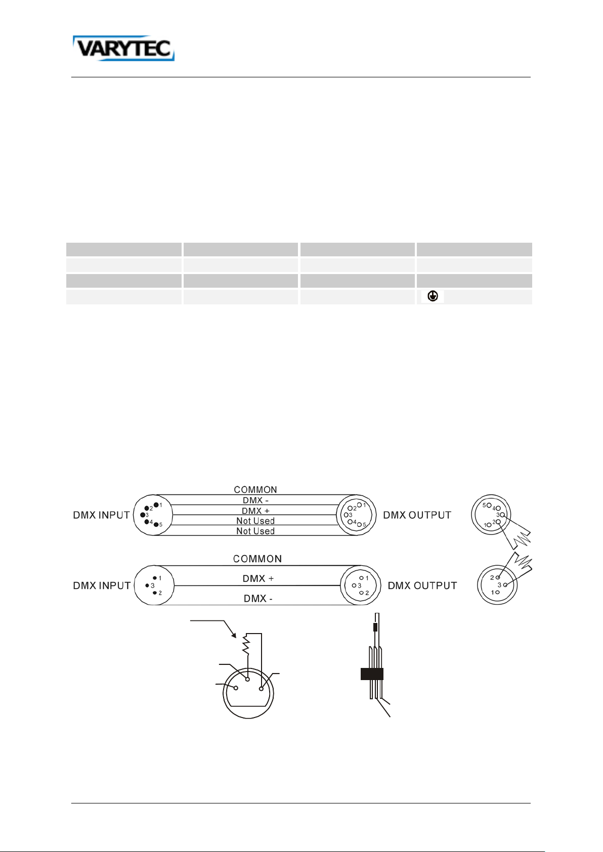
3.2. DMX connections
To make a DMX512 connection go ahead like it is described in the picture. Make sure that you
use shielded cable. 3pole or 5pole XLR cables are suitable.
3.3. DMX connection w i th terminator
Where the DMX cable has to run a long distance or the equipment is operated in an electrically noisy
environment like a disco for installations, we recommend using a DMX terminator. This prevents
corruption of the digital control signal by electrical noise. The DMX terminator is simply an XLR
connector with a 120 Ω resistor between pins 2 and 3, which is then plugged into the XLR output
socket of the last device in the series. Please look to the bottom drawings.
If you using a controller with 5 pins DMX output, you need to use a 5 to 3 pin adapter-cable.
7 / 16
Page 8
1 2 3 4 5 6
DIP Switch
#9 0 0 0 0 0 0 0 0 1 1 1 1 1 1 1
1
#8 0 0 0 0 1 1 1 1 0 0 0 0 1 1 1 1
#7 0 0 1 1 0 0 1 1 0 0 1 1 0 0 1
1
1 2 3 4 5 6
1 2 3 4 5 6
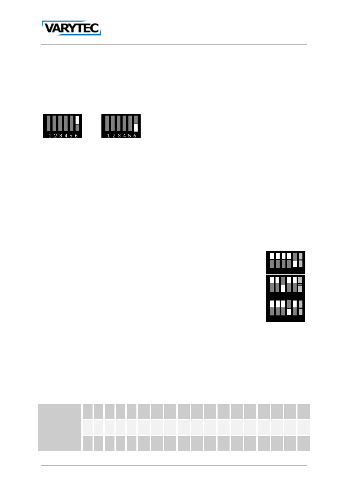
4. Bedienung
4.1. Lamp power setting
The Strobe Xenon 3000DMX has two operation modes:
High power: maximum intensity
Low power: reduces output and extends lamp life
The mode is set with Pin 6 at the Mode Dip-Switch.
High power Low power
4.2. Compatible lamps
For the Strobe Xenon 3000DMX are two different lamp available: the XOP 7-OF and the XOP 15-OF.
The XOP 7 operates on voltages from 90V to 260V and is recommended for use with the main
suppliers under 200V. The XOP 15 operates on voltages from 125V to 260V and is recommended for
use with mains suppliers over 200V.
Installing any other lamp may create a safety hazard or damage the fixture!
4.3. DMX modes
The DMX modes are selected with the Mode Dip-Switch. .
With mode 1 (1 channel) you can control the Strobe Xenon 3000DMX with one
channel. You can control the flash rate.
With mode 2 (3 channels) you can control intensity, flash duration and flash rate.
With mode 3 (4 channels) you can control intesity, flash duration, flash rate and six
special effects.
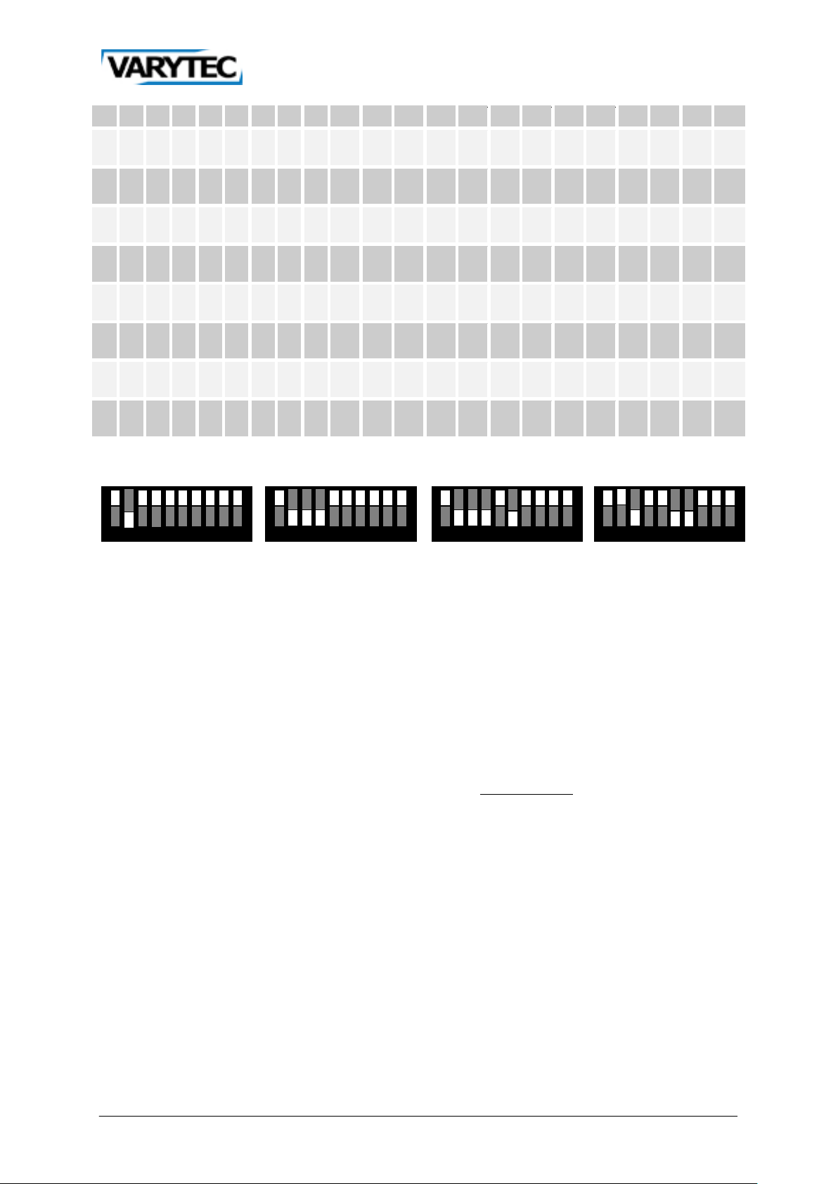
4.4. Setting the DMX address
The start address is the first channel, which gets the control signals from a controller. It can be set
from 1-511. To control every device on ist own, every device needs ist own address. It is not allowed
that an address overlaps another.
Set the DMX address as shown in the chart below. 0 means the pin is set to OFF, 1 means the pin is
set to ON. Pin 10 has to be set OFF for DMX operating.
0=OFF, 1=ON
8 / 16
Page 9

#6 0 1 0 1 0 1 0 1 0 1 0 1 0 1 0
1
#1 #2 #3 #4 #5 0 0 0 0 0 32 64 96
128 160 192 224 256 288 320 352 384 416 448 48
1 0 0 0 0 1
33 65 97
129 161 193 225 257 289 321 353 385 417 449 48
0 1 0 0 0 2
34 66 98
130 162 194 226 258 290 322 354 386 418 450 482 1 1 0 0 0 3
35 67 99
131 163 195 227 259 291 323 355 387 419 451 48
0 0 1 0 0 4
36 68 100 132 164 196 228 260 292 324 356 388 420 452 484 1 0 1 0 0 5
37 69 101 133 165 197 229 261 293 325 357 389 421 453 48
0 1 1 0 0 6
38 70 102 134 166 198 230 262 294 326 358 390 422 454 48
1 1 1 0 0 7
39 71 103 135 167 199 231 263 295 327 359 391 423 455 487 0 0 0 1 0 8
40 72 104 136 168 200 232 264 296 328 360 392 424 456 48
1 0 0 1 0 9
41 73 105 137 169 201 233 265 297 329 361 393 425 457 48
0 1 0 1 0 10 42 74 106 138 170 202 234 266 298 330 362 394 426 458 490 1 1 0 1 0 11 43 75 107 139 171 203 235 267 299 331 363 395 427 459 49
0 0 1 1 0 12 44 76 108 140 172 204 236 268 300 332 364 396 428 460 49
1 0 1 1 0 13 45 77 109 141 173 205 237 269 301 333 365 397 429 461 493 0 1 1 1 0 14 46 78 110 142 174 206 238 270 302 334 366 398 430 462 49
1 1 1 1 0 15 47 79 111 143 175 207 239 271 303 335 367 399 431 463 49
0 0 0 0 1 16 48 80 112 144 176 208 240 272 304 336 368 400 432 464 496 1 0 0 0 1 17 49 81 113 145 177 209 241 273 305 337 369 401 433 465 49
0 1 0 0 1 18 50 82 114 146 178 210 242 274 306 338 370 402 434 466 49
1 1 0 0 1 19 51 83 115 147 179 211 243 275 307 339 371 403 435 467 499 0 0 1 0 1 20 52 84 116 148 180 212 244 276 308 340 372 404 436 468 50
1 0 1 0 1 21 53 85 117 149 181 213 245 277 309 341 373 405 437 469 50
0 1 1 0 1 22 54 86 118 150 182 214 246 278 310 342 374 406 438 470 50
1 1 1 0 1 258111518212427313437404347
50
0
1
3
5
6
8
9
1
2
4
5
7
8
0
1
2
9 / 16
Page 10
1 2 3 4 5 6 7 8 9 10
3 5 7 9 1 3 5 7 9 1 3 5 7 9 1
3
0 0 0 1 1 24 56 88 120 152 184 216 248 280 312 344 376 408 440 472 504 1 0 0 1 1 25 57 89 121 153 185 217 249 281 313 345 377 409 441 473 50
0 1 0 1 1 26 58 90 122 154 186 218 250 282 314 346 378 410 442 474 50
1 1 0 1 1 27 59 91 123 155 187 219 251 283 315 347 379 411 443 475 507 0 0 1 1 1 28 60 92 124 156 188 220 252 284 316 348 380 412 444 476 50
1 0 1 1 1 29 61 93 125 157 189 221 253 285 317 349 381 413 445 477 509 0 1 1 1 1 30 62 94 126 158 190 222 254 286 318 350 382 414 446 478 51
1 1 1 1 1 31 63 95 127 159 191 223 255 287 319 351 383 415 447 479 51
1 2 3 4 5 6 7 8 9 10
1 2 3 4 5 6 7 8 9 10
1 2 3 4 5 6 7 8 9 10
Channel 2
Channel 14
Channel 46
Channel 100
Example:
5
6
8
0
1
4.5. Standalone mode
This chapter describes how you can control the Strobe Xenon 3000DMX without a controller.
• Set pin 1 of the Mode-DIPs on.
• Set the pins 2-5 off.
• Pin 6 using normal.
Use the Address-Dip-Pins for setting the flash rate (255 steps). Pin 9 allows a blinder function. The
value required to achieve a desired flash rate can be calculated as follows:
𝐷𝐼𝑃 − 𝑆𝑤𝑖𝑡𝑐ℎ − 𝑉𝑎𝑙𝑢𝑒 = 261 − 2 ∗
𝑁𝑒𝑡𝑓𝑟𝑒𝑞𝑢𝑒𝑛𝑐𝑖𝑒
𝐹𝑙𝑎𝑠ℎ − 𝑅𝑎𝑡𝑒
To achieve a flash rate of 10 flashes per second on a 50Hz power supply, for example, the Dip value
is 251. To select the blinder effect instead, set pin 9 to ON.
10 / 16
Page 11

Value
0 5 No function
6
249
Strobe slow-fast
250
255
Full on
Channel
Value
from
Value to
Function
1 0 255
Dimmer 0-100%
2 0 255
Flash duration short-long
3 0 255
Flash rate slow-fast
Channel
Value
from
Value to
Function
1 0 255
Dimmer 0-100%
2 0 255
Flash duration short-long
3 0 255
Flash rate slow-fast
0 5 Off 6 42
Dimming upwards
43
85
Dimming downwards
86
128
Dimming upwards/downwards
129
171
Random
172
214
Strobe
215
255
Spikes
5. DMX chart
5.1. Mode 1 (1 channel)
Channel
1
from
Value to Function
5.2. Mode 2 (3 channels)
5.3. Mode 3 (4 channels)
4
Note: Enable channel 4 with Mode-Dip-Switch 4.
11 / 16
Page 12

6. Replace the lamp
1. Disconnect the fixture from the power supply system and allow the capacitor to discharge for 1
min and cool down the fixture.
2. Remove the screw on the sides and open the front glass cover.
3. Disconnect the lamp wires at the screw terminal.
4. Lift the old lamp out of the holder.
5. Lay the new lamp on the front glass above the lamp clips, with the end with two wires on the
side close to the main cable.
6. Connect the two wires with the white isolation to the outside terminal on each end. Connect
the wire with clear insulation to the inside terminal on the closest to the main cables. Push the
isolation for each wire as far as will go into the block.
7. Press the lamp into the clips.
12 / 16
Page 13

Power supply
Voltage
AC90-240V, 50/60Hz
Power consumption max.
3500 W
Battery
No
Light source
LM type
XOP1500 Xenon Flashtube
Power
3000 W
Number/Power
1/3000 W
Optics
Flash rate
0-25 Flashes/s
Connections
Current in
Open cable and
Current out
No
XLR in/out
3Pin, 5Pin
Controlling
Sound-to-light
No
Automatic
Yes
Master-Slave
Yes
DMX512
1/3/4 Channels
Hardware
Protection class
IP20
Dimensions (L/B/H)
486x258x320mm
Weight
7 kg
7. Technical data
13 / 16
Page 14

14 / 16
Page 15

15 / 16
Page 16

Importeur:
B & K Braun GmbH
Industriestraße 2
D-76307 Karlsbad
www.bkbraun.com
info@bkbraun.com
16 / 16
 Loading...