

Page 1
Manual
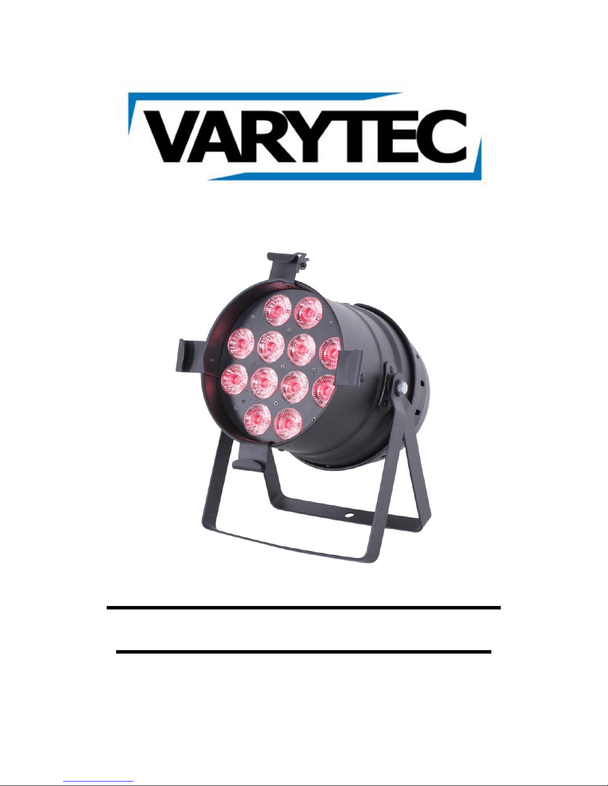
LED PAR 64 floor 12x8W
RGBWAUV incl. remote
Page 2

2 / 16
Table of contents
1. Safety instructions ............................................................................................................................ 3
1.1. For safe and efficient operation ............................................................................................... 3
2. Designated use ................................................................................................................................ 4
2.1. Overhead installation ............................................................................................................... 5
3. Introduction ....................................................................................................................................... 7
4. Connections ..................................................................................................................................... 7
4.1. Electrical connections .............................................................................................................. 7
4.2. DMX connections .................................................................................................................... 7
4.3. DMX connection with terminator.............................................................................................. 7
5. Control .............................................................................................................................................. 8
5.1. Structure of the menu .............................................................................................................. 8
5.2. IR remote ................................................................................................................................. 9
6. DMX chart ...................................................................................................................................... 10
6.1. Mode 1 (1 channel) ................................................................................................................ 10
6.2. Mode 2 (6 channels) .............................................................................................................. 11
6.3. Mode 3 (7 channels) .............................................................................................................. 11
6.4. Mode 4 (10 channels) ............................................................................................................ 11
7. Technical data ................................................................................................................................ 13
Page 3
3 / 16
1. Safety instructions
This device is suitable for indoor use (not outdoors) only.
All modifications to the device will void the warranty.
Repairs are to carry out by skilled personnel only.
Use only fuses of the same type and original parts as spare parts.
Protect the unit from rain and humidity to avoid fire and electric shocks.
Make sure to unplug the power supply before opening the housing.
1.1. For safe and efficient operation
Be careful with heat and extreme temperature
Avoid exposing it to direct rays of the sun or near a heating appliance.
Not put it in a temperature bellow 32°F /0°C, or exceeding 104°F /40°C.
Keep away from humidity, water and dust
Do not place the set in a location with high humidity or lots of dust.
Containers with water should not be placed on the set.
Keep away from sources of hum and noise
Such as transformer motor, tuner, TV set and amplifier.
To avoid placing on un-stable location
Select a level and stable location to avoid vibration.
Do not use chemicals or volatile liquids for cleaning
Use a clean dry cloth to wipe off the dust, or a wet soft cloth for stubborn dirt.
If out of work, contact sales agency immediately
Any troubles arose, remove the power plug soon, and contact with an engineer for repairing, do not
open the cabinet by yourself, it might result a danger of electric shock.
Take care with the power cable
Never pull the power cable to remove the plug from the receptacle, be sure to hold the plug. When not
using the device for an extended period of time, be sure to disconnect the plug from the receptacle.
Important:
Damages caused by the disregard of this user manual are not subject to warranty. The dealer will not
accept liability for any resulting defects or problems. Make sure the electrical connection is carried out
by qualified personnel. All electrical and mechanical connections have to be carried out according to
the European safety standards.
Page 4

4 / 16
2. Designated use
This device was developed for professional use on stages, in discos, theatres etc. The device is only
approved for a connection up to 230V 50/60 Hz AC voltage and only for indoor use.
Regular breaks during operation increase the lifetime of your device.
Avoid convulsions or any form of forceful impact during the installation or the start-up of the device.
Make sure that the device is not exposed excessive heat, humidity or dust at the place of installation.
Take care that no cables are lying around. You would endanger your own safety and also the safety of
a third party.
It is not allowed to operate or store the device in an environment in which spray water, rain, humidity
or fog is expected. Humidity or very high atmospheric humidity could reduce the isolation of the device
and could cause deathly electric shocks. If you use fog devices the device has not be exposed to a
direct smoke jet. There has to be a safety distance of at least 0,5m between this device and the fog
machine. Make sure that the saturation of the fog has to enable a visibility of at least 10m.
The ambient temperature has to be between 0°C and +40°C. Avoid direct sunlight and close proximity
to heaters. You have also to attend it during the transport in closed motor vehicles.
Operate the device not during thunderstorms. Surge voltages could destroy the device. Unplug the
power supply during thunderstorms.
During the installation the use of the mounting bracket is obligatory.
Surrounding objects or surfaces should not be in contact with the device.
Make sure that during the installation and removal of the device the area below the place of
installation is basically cordoned off. This also applies to implementation of service.
The device has basically been protected by a suitable safety.
Make familiar yourself with the functions of the device before start-up. People without the experience
should not handle with the device. The most cause of functional disorder is inappropriate handling.
Do not use chemicals or volatile liquids for cleaning. Use a clean dry cloth to wipe off the dust, or a
wet soft cloth for stubborn dirt.
For transport use the original packing or designated accessory to avoid damages during the transport.
For reasons of safety unauthorized changes are forbidden.
A usage of the device which differs from usages which are described in this manual can cause
damages of the device. In that case the warranty expires. Additional you should notice that every
differed usage is related with dangers and can cause e.g. an electrical short, fire, electric shock or
crash.
Page 5
5 / 16
2.1. Overhead installation
Danger of life!
You have to observe the regulations of BGV C1 (formerly VBG 70) and
EN60598-2-17 Installations are to carry out by skilled personnel only.
The suspension devices have to be build and measured so they can withstand for an hour the tenfold
of the payload without suffering a permanent detrimental deformation.
Basically installation has to be made by using a second separate suspension. This can be e.g. a
suitable net. The second suspension must be designed and attached so no part of the installation can
fall down in case of failure.
During construction, reconstruction and deconstruction unnecessary stay in the range of moving
areas, on lightning bridges, under elevated work stations or any other danger zones is forbidden.
The operator is obliged to following safety-related and mechanical facilities:
- Before the first start-up or after critical changes before restarting it has to be checked by an
expert.
- Review in the frame of the inspection test at least all four years by an expert. .
- Review by a qualified person at least once a year.
How to carry out the overhead installation:
In tidal fall you should install the device out of the lounge area of people
IMPORTANT! Overhead installation requires a high level of experience. This includes knowledge of
calculating the payload, used installation material and safety inspections of the used material and the
projector whereas the required experience is not limited to this. Do not try to carry out installation
yourself under any circumstances if you are not qualified. Contact a professional installer. An
inappropriate installation can lead to injuries and/or damaged properties.
It is not allowed to install the device in the grip area of people.
If the device may hang from the ceiling or from high beams, the use of truss systems is mandatory.
The device may not be installed so it can swing freely in the room.
Please note: Crashing down items can cause serious injuries! Do not install the projector, if you doubt
the safety of a possible installation form!
Before installation make sure that the mounting surface has the ability to carry the tenfold point load of
the own weight of the device.
Mount the device with the mounting-bracket to your trussing system using an appropriate clamp.
During overhead installation the device must be always secured by a safety rope which is designed to
hold the twelvefold weight of device. Only safety ropes with quick-release safety fastener elements
may be used. Hang up the safety rope in the hole of the mounting bracket. Direct the rope over the
truss or an appropriate fastening point. Hang up the end in the fastening element and tie up the
locking nut. A safety rope once exposed to failing load or damaged may not be used furthermore.
Page 6

6 / 16
The maximum drop exceed must not exceed 20cm.
A safety rope once exposed to failing load or damaged may not be used furthermore.
Adjust the desired inclination angle via the mounting bracket and tighten the screw.
Page 7
7 / 16
3. Introduction
Thank you for buying the LED PAR 64 floor 12x8W RGBWAUV incl. remote. It is a powerful device.
For a successful installation and operation, please read this manual carefully.
4. Connections
4.1. Electrical connections
If you wish to change the power supply settings, see the chapter Appendix. Connect the fixture to the
mains with the enclosed power cable and plug. The earth has to be connected.
Cable (EU)
Cable (US)
Pin
International
Brown
Black
Live L Light blue
White
Neutral
N
Yellow/Green
Green
Earth
4.2. DMX connections
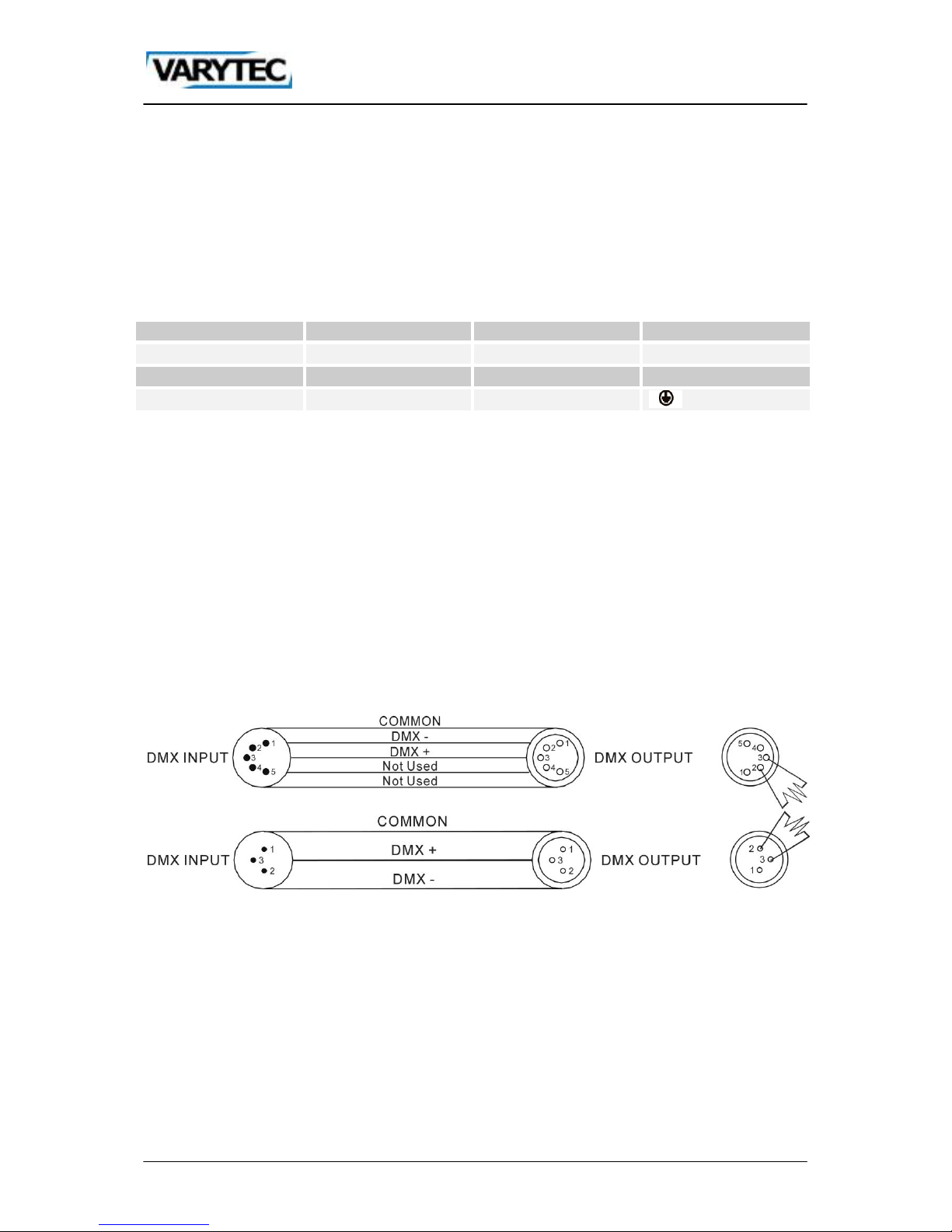
To make a DMX512 connection go ahead like it is described in the picture. Make sure that you use
shielded cable. 3pole or 5pole XLR cables are suitable.
Important! After the last device the line has to be terminated. In order to do this you have to solder a
120Ω resistor between the pins Data + and Data -. You can solder this end resistor on a 3pin or 5pin
XLR: Plug this adapter into the DMX output of the device.
4.3. DMX connection with terminator
Where the DMX cable has to run a long distance or the equipment is operated in an electrically noisy
environment like a disco for installations, we recommend using a DMX terminator. This prevents
corruption of the digital control signal by electrical noise. The DMX terminator is simply an XLR
connector with a 120 Ω resistor between pins 2 and 3, which is then plugged into the XLR output
socket of the last device in the series. Please look to the bottom drawings.
Page 8
8 / 16
5. Control
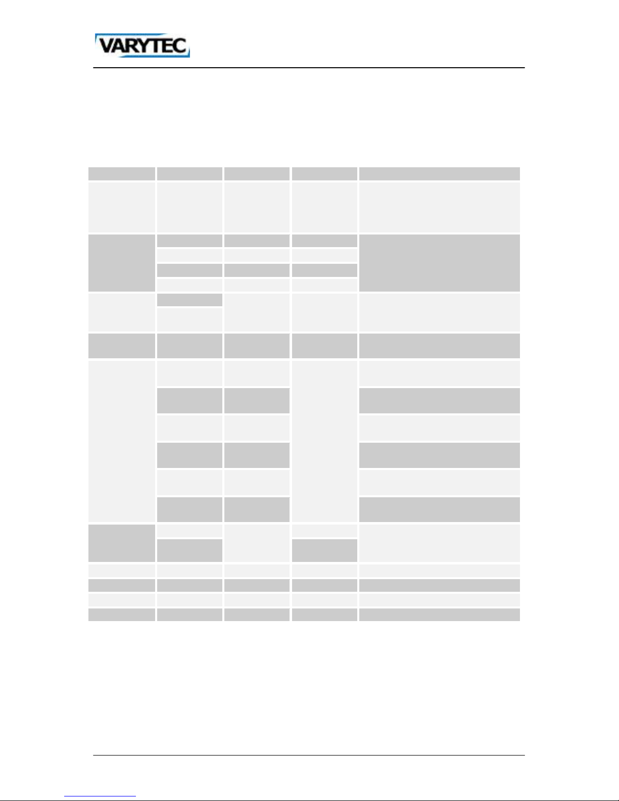
Press MENU, to get into the menu. With UP/DOWN you can choose the required submenu. Confirm
with ENTER. Do your settings with UP/DOWN and confirm with ENTER. To step back press MENU
again.
5.1. Structure of the menu
Menu
Submenu 1
Submenu 2
Submenu 3
Function
Addr
A001 – A512
Setting the DMX address. If you
want to use the device in DMX
mode you have to be in this point of
menu.
Chnd
1Ch
Choose one of the DMX modes. If
you have chosen a DMX mode,
step back to the point of menu
Addr.
6Ch
7Ch
10Ch
Auto
Aut1
Sp-11 – Sp-9
St01 – St99
Choose one of the automatic
programs and set the speed of the
program and strobe. Slow-fast.
Aut2
CoLo
Co01 – Co51
St00 – St99
Choose a preset color and setting
the speed of the strobe. Slow-fast.
Stat
red
r000 – r255
St00 – St99
Dimmer red 0-100% and set the
speed of the strobe. Slow-fast.
Gree
G000-G255
Dimmer green 0-100% and set the
speed of the strobe. Slow-fast.
bLue
b000 – b255
Dimmer blue 0-100% and set the
speed of the strobe. Slow-fast.
Uhit
U000 – U255
Dimmer white 0-100% and set the
speed of the strobe. Slow-fast.
Anbe
A000 – A255
Dimmer amber 0-100% and set the
speed of the strobe. Slow-fast.
UV
P000 – P255
Dimmer UV 0-100% and set the
speed of the strobe. Slow-fast.
Soun
Sou1
Sen0 – Sen9
Choose one sound-to-light mode
and set the sensitivity of the
microphone. Low-high.
Sou2
SLAv
SLA
Activates the Master-slave mode.
rEno
On/Off
(De-)Activates the remote.
tenp
Cuxx
Shows the current temperature.
uer
uxx
Shows the current software version.
Page 9
9 / 16
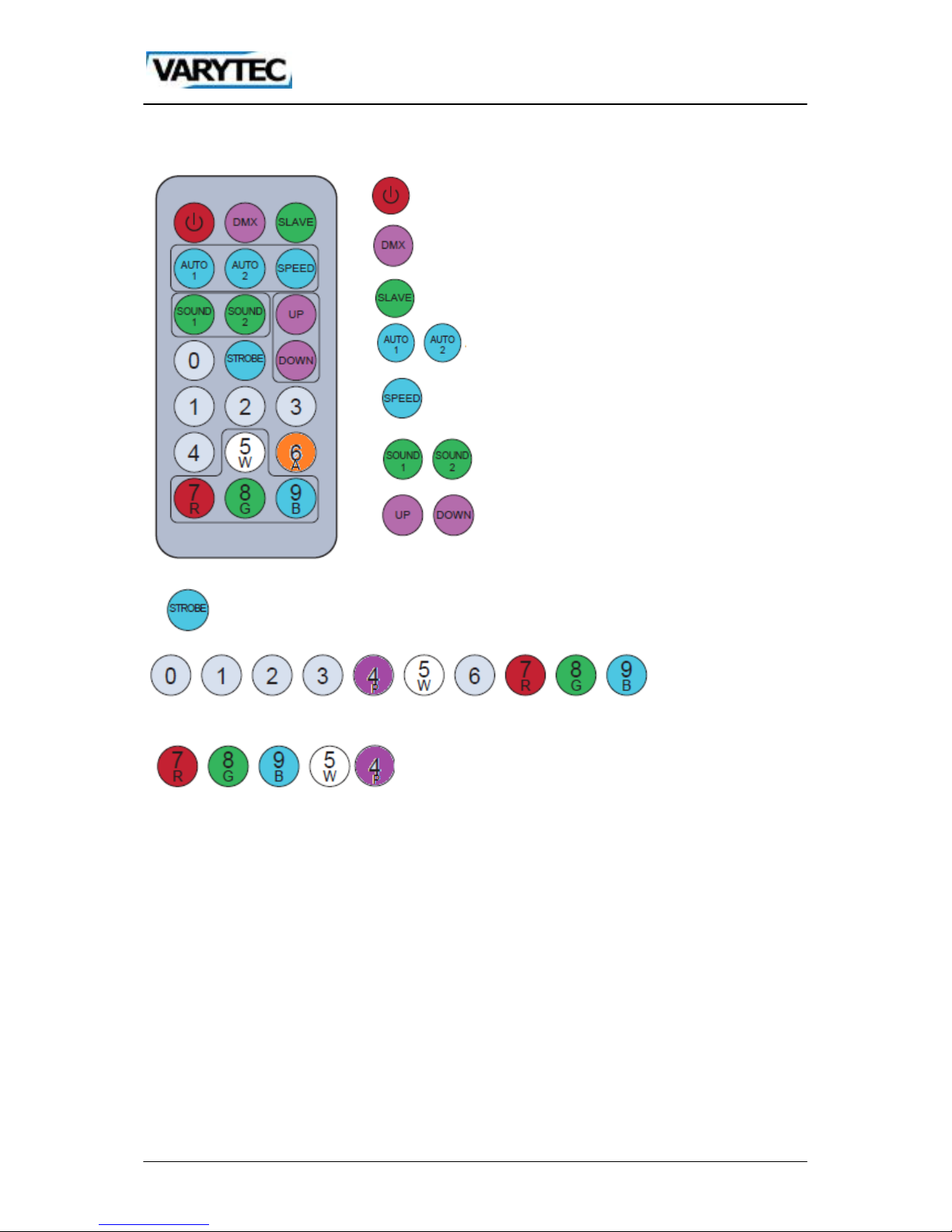
5.2. IR remote
Power On/Off
You can set the DMX address when this button is
pressed. Double click = Channel mode
Master/Slave
Auto-Mode 1/2
Speed
Sound-Mode 1/2
You can choose a program or number.
Strobe
You can use this
number buttons to
adjust numerical in
any program mode.
You can choose a color.
Page 10
10 / 16
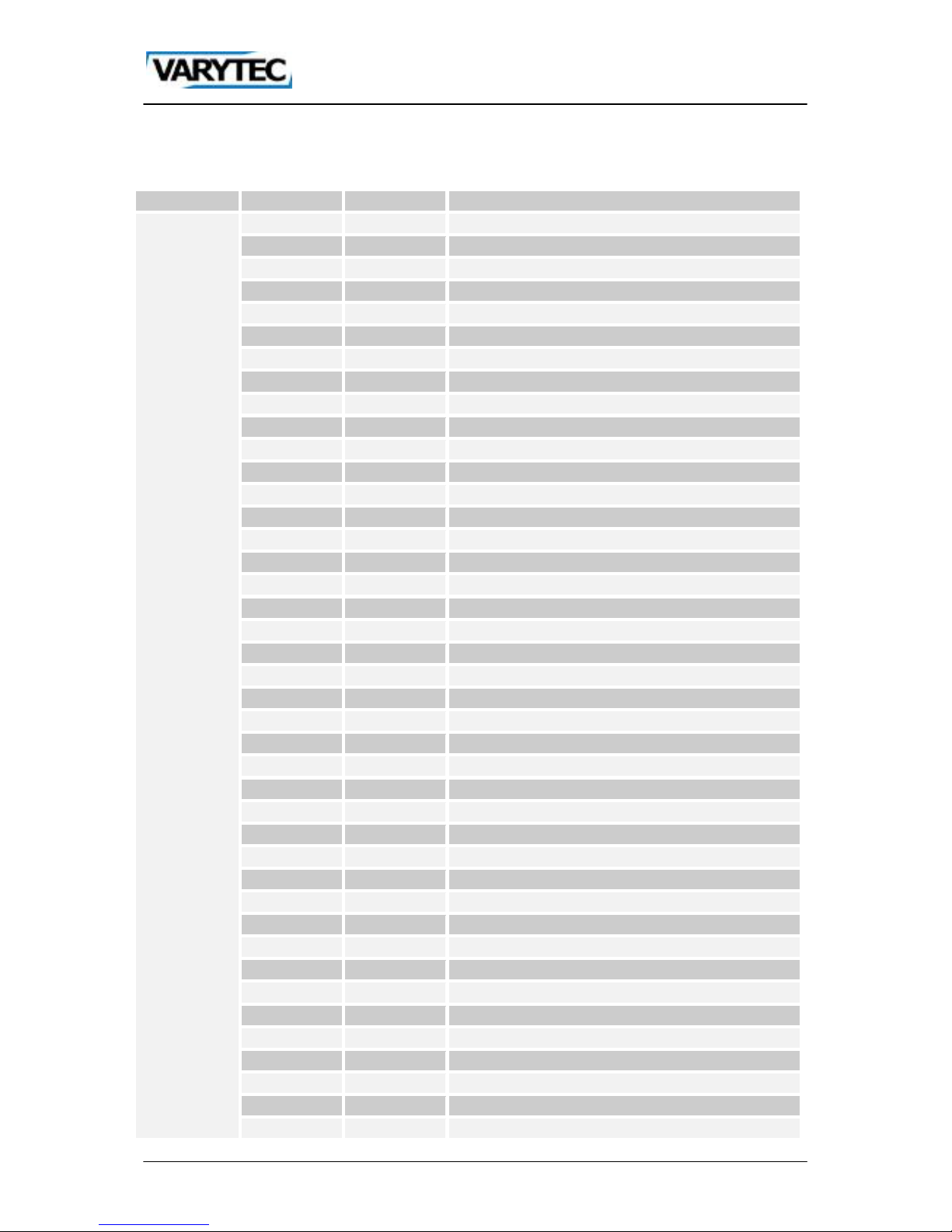
6. DMX chart
6.1. Mode 1 (1 channel)
Channel
Value from
Value to
Function
1
0 No function
1 4 Color 1
5 9 Color 2
10
14
Color 3
15
19
Color 4
20
24
Color 5
25
29
Color 6
30
34
Color 7
35
39
Color 8
40
44
Color 9
45
49
Color 10
50
54
Color 11
55
59
Color 12
60
64
Color 13
65
69
Color 14
70
74
Color 15
75
79
Color 16
80
84
Color 17
85
89
Color 18
90
94
Color 19
95
99
Color 20
100
104
Color 21
105
109
Color 22
110
114
Color 23
115
119
Color 24
120
124
Color 25
125
129
Color 26
130
134
Color 27
135
139
Color 28
140
144
Color 29
145
149
Color 30
150
154
Color 31
155
159
Color 32
160
164
Color 33
165
169
Color 34
170
174
Color 35
175
179
Color 36
180
184
Color 37
185
189
Color 38
190
194
Color 39
195
199
Color 40
Page 11
11 / 16
200
204
Color 41
205
209
Color 42
210
214
Color 43
215
219
Color 44
220
224
Color 45
225
229
Color 46
230
234
Color 47
235
239
Color 48
240
244
Color 49
245
249
Color 50
250
255
Color 51
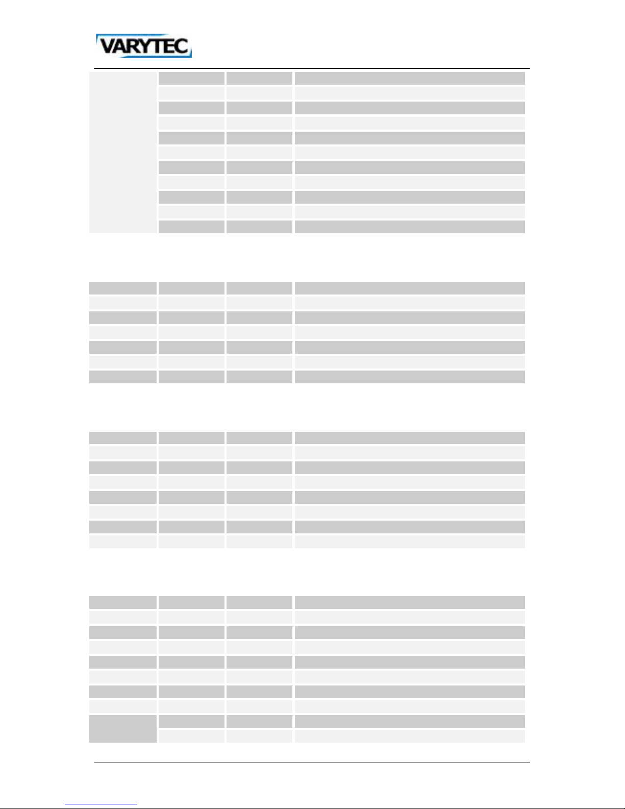
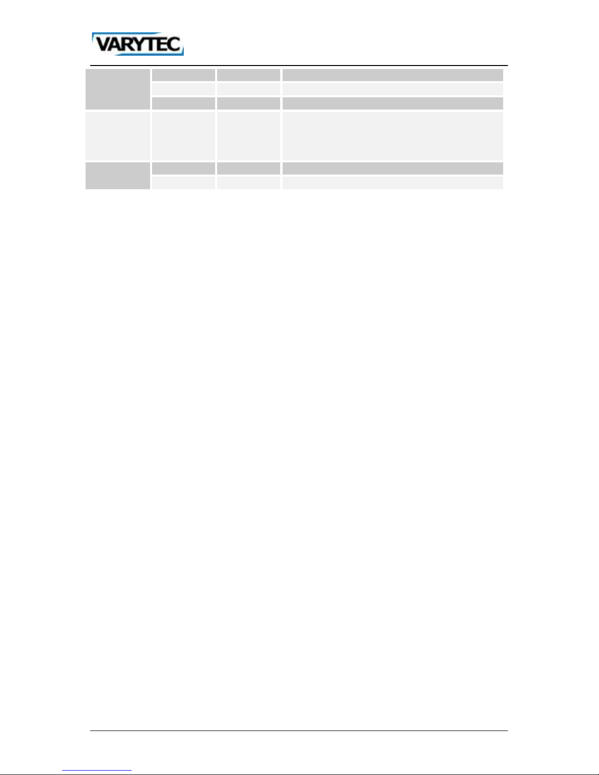
6.2. Mode 2 (6 channels)
Channel
Value from
Value to
Function
1 0 255
Dimmer red 0-100%
2 0 255
Dimmer green 0-100%
3 0 255
Dimmer blue 0-100%
4 0 255
Dimmer white 0-100%
5 0 255
Dimmer amber 0-100%
6 0 255
Dimmer UV 0-100%
6.3. Mode 3 (7 channels)
Channel
Value from
Value to
Function
1 0 255
Dimmer 0-100%
2 0 255
Dimmer red 0-100%
3 0 255
Dimmer green 0-100%
4 0 255
Dimmer blue 0-100%
5 0 255
Dimmer white 0-100%
6 0 255
Dimmer amber 0-100%
7 0 255
Dimmer UV 0-100%
6.4. Mode 4 (10 channels)
Channel
Value from
Value to
Function
1 0 255
Dimmer 0-100%
2 0 255
Dimmer red 0-100%
3 0 255
Dimmer green 0-100%
4 0 255
Dimmer blue 0-100%
5 0 255
Dimmer white 0-100%
6 0 255
Dimmer amber 0-100%
7 0 255
Dimmer UV 0-100%
8
0
50
No function
51
101
Automatic program 1
Page 12
12 / 16
102
152
Automatic program 2
153
203
Sound-to-light mode 1
204
255
Sound-to-light mode 2
9 0 255
If channel 8 has the value 51-152, you can set the
speed of the automatic programs with this channel
Slow-fast. If channel 8 has the value 153-255, you
can set the sensitivity of the microphone. Low-high.
10
0 9 No function.
10
255
Strobe slow-fast
Page 13
13 / 16
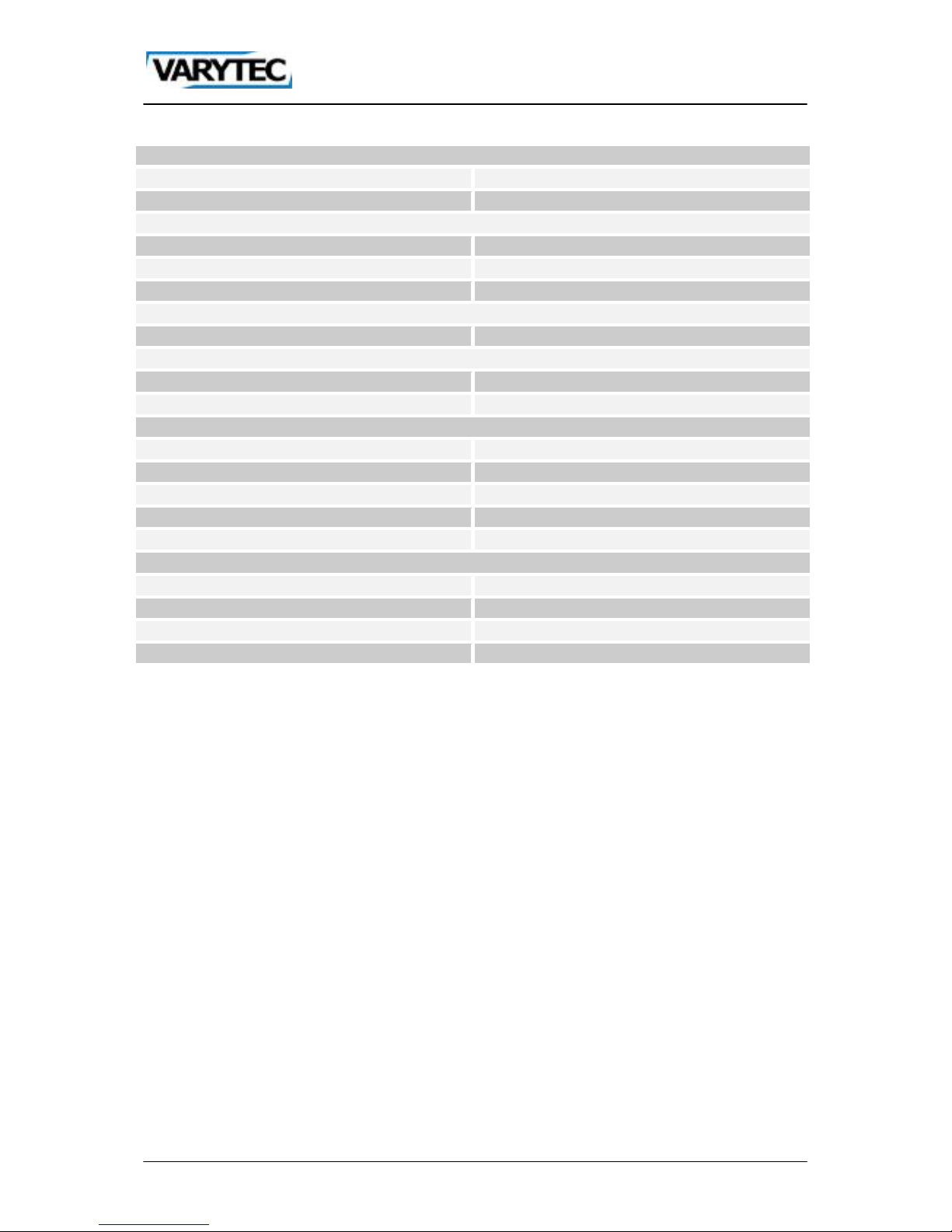
7. Technical data
Power supply
Voltage
AC 110-240 V; 50/60 Hz
Power consumption max.
110 W
Light source
LM type
LED 6in1
Power
8 W
Number / Power
6 x 8W
Optics
Beam angle
25°
Connections
Strom in
Schutzko cable
XLR in/out
3pol
Controlling
Sound-to-light
Yes
Automatic
Yes
Master-Slave
Yes
DMX512
Yes
Number of channels
1/6/7/10 channels
Hardware
Protection class
IP20
Skill
Indoor
Dimensions (L/B/H)
255 x 265 x 390 mm
Weight
2,78 kg
Page 14

14 / 16
Page 15

15 / 16
Page 16
16 / 16
Importer:
B & K Braun GmbH
Industriestraße 2
D-76307 Karlsbad
www.bkbraun.com
 Loading...