

Page 1

Manual
Beam R2
Page 2

2 / 17
Table of contents
1. Safety instructions ............................................................................................................................ 3
1.1. Instructions for a safe and efficient operation .......................................................................... 3
1.2. Further safety instructions ....................................................................................................... 4
1.3. Designated use ........................................................................................................................ 4
1.4. Overhead installation ............................................................................................................... 5
2. Statement ......................................................................................................................................... 7
2.1. Product description .................................................................................................................. 7
2.2. Introduction to the product ....................................................................................................... 7
2.2.1. Technical Data ................................................................................................................. 7
3. Packaging ......................................................................................................................................... 9
3.1. Contents .................................................................................................................................. 9
3.2. Transport lock .......................................................................................................................... 9
3.3. Lamp types .............................................................................................................................. 9
3.3.1. Changing the lamp ........................................................................................................ 10
4. Control ............................................................................................................................................ 11
4.1. Description of the display section .......................................................................................... 11
4.1.1. Structure of the menu .................................................................................................... 11
4.2. DMX Chart ............................................................................................................................. 13
Page 3

1. Safety instructions
•
This Device is
•
All modifications will void the warranty
• Repairs
have to
•
Only use fuses of the same type and original parts as spare parts.
•
Protect the Un
•
Make sure to unplug the power supply before opening the housing.
1.1.
Instructions for a safe and efficient operation
Please read careful through this manual before the first start
All persons which are entrusted with installation, start
device have to:
•
Show a corresponding competence.
•
Follow the lines of this manual.
•
Face this manual as part of the product.
•
Keep this manual over the lifetime of the product.
•
Pass this manual to new owners of the
Be careful with heat and extreme temperature
Only use the device in a place where no extreme temperatures will occur.
Do not keep it in a temperature bellow 32°F (0°C
Avoid exposing it to direct rays of the sun or near
You have to attend that with an ambient temperature von 40°C it is not allowed that the
humidity exceeds 50%.
Keep away from humidity, water and dust
Do not place it in a location with
high humidity or lots of dust.
Containers with liquid
should not be placed on
Avoid placing it on un-
stable location
Select a level and stable location to avoid vibration.
Do not use chemicals or volatile liquids for cleaning
Use a clean dry cloth to wipe off the dust
stubborn dirt.
Before cleaning the device make sure you disconnect the powerplug.
If out of work, contact sales agency
If any troubles occurs
, remove the power plug
do not open the cabinet by yourself, it might result
Take care with the power cable
Never pull the power cable to remove the plug from the receptacle, be sure to hold the plug
Make sure that it isn’t possible to squeeze or damage the power cable with sharp edges. Assure
yourself with regular checks that there are no damages to the power cable or
When not using the device for an extended period of time, be
receptacle.
3 / 17
suitable for indoor use only.
.
be carried out by skilled personnel only.
it from rain and humidity to avoid fire and e
lectric shocks.
-up.
-up,
operation, maintenance and repair of this
device.
), or exceeding 104°F (40°C).
a heating appliance.
or near the device.
. Metall Parts can be cleaned with
a wet soft cloth for
soon
immediately
, and contact with an engineer for repairing,
in a danger of electric shock.
the device itself.
sure to disconnect the plug from the
relative
itself.
Page 4

IMPORTANT:
Damages caused by the disregard of this user manual are not subject to warranty. The dealer will not
accept liability for any resulting defects or problems.
by qualified personnel
. All electrical and mechanical connections have to be carried out according to
the European safety standards.
1.2.
Further safety instructions
IMPORTANT!
Handle with the dangerous electric voltages carefully.
With this
voltage there is the danger to get a life
After taken the device from a cold room to a warm room, it is not allowed to activate the device. It is
possible that thereby emerged condensed water damages the device.
it reached ambient temperature.
Make sure that the voltage which i
Don’t switch the device in short time intervals (e.g. in second cycle) on or off.
Keep away children and laymen of
Health risk!
Don’t look directly into the light source. At certain circumstances it is
possible that some people get epileptic seizures. This is especially true for
individuals whose epilepsy was determined by a doctor.
1.3. Designated use
This device was developed for professional use on stages, in discos, theatres etc. The device is only
approved for a connection up to 230V 50/60 Hz AC voltage
Regular breaks during operation increase the lifetime of your device.
Avoid vibrations or any fo
rm of forceful im
device.
Make sure that the device is not exposed excessive heat, humidity or dust at the place of installat
Take care that no cables are lying around. You would endanger
a third party.
It is not allowed to operate or store the device in an environment in which spray water, rain, humidity
or fog is expected. Humidity or very high atmospheric humidity could reduce the isolation of the d
and could cause deathly electric shocks. If yo
direct smoke jet. There has to be a safety distance of at least 0.5m between this device and the fog
machine. Make sure that the saturation of the fog
Do not o
perate the device during thunderstorms. Surge volt
device from the
power supply during thunderstorms.
For installation the use of the mounting bracket is obligato
Surrounding objects or surfaces should not be in contact with the device.
Make sure that during the installation and removal of the device the area below the place of
installation is basically cordoned off. This also applies to implementation of serv
4 / 17
Make sure the
electrical connection i
-
threatening electric shock.
Do not a
ctivate
t is connected to does
not exceed the specified values.
f the device.
.
pact during the installation, the start-up
or Operation
your own safety and also the safety of
u use fog devices the device
may not
has to enable a visibility of at least 10m.
ages could destroy the device.
ry.
ice.
s carried out
the device until
of the
ion.
evice
be exposed to a
Unplug the
Page 5

The device has to
be protected by a suitable safety
Make yourself
familiar with the functions of the device before start
s
hould not handle the device. The most cause of functional disorder is inappropriate hand
U
se the original packing or designated accessory
For reasons of safety unauthorized changes are forbidden.
A usage of the device which differs from usages which are described in this manual can cause
damages of the d
evice. In that case the warranty expires. Additional you should notice that every
differed usage is related with dangers and can cause e.g. an electrical short, fire, electric shock or
crash.
1.4.
Overhead installation
Danger of life!
You have to observe the
EN60598-2-
17. If there are more regulations for the area of designated use
they have to be adhered, too. Therefore i
skilled personnel only.
The suspension devices have to be bui
payload for one hour without suffering a permanent detrimental deformation.
Basically installation has to be done by using a second separate suspension. This can be e.g. a
suitable net. The second su
spension must be designed and attached so no part of the installation can
fall down in case of failure.
During construction, reconstruction and deconstruction unnecessary stay in the range of moving
areas, on lightning bridges, under elevated work stations or any other danger zones is forbidden.
The operator is obliged to following safety
• Before the first start-
up or after critical changes before restarting it has to be checked by an
expert.
•
Review in the frame of the inspection test at least all four years by an expert. .
•
Review by a qualified person at least once a year
How to carry out the overhead installation:
If possible you should install the device out of areas where people are able to stay.
IMPORTANT!
Overhead installation requires a high level of experience. This includes knowledge of
calculating the payload, u
sed installation material and safety inspections of the used material and the
projector whereas the required experience is not limited to this. Do not try to carry out installation
yourself under any circumstances if you are not qualified. Contact a qualif
inappropriate installation can lead to injuries and/or damaged properties.
It is not allowed to install the device in the grip area of people.
If the device may hang from the ceiling or from high beams, the use of truss systems is mandato
The device may not be installed so it can swing freely in the room.
Please note: Crashing down items can cause serious injuries! Do not install the projector, if you doubt
the safety of a possible installation form!
Mount the device with the mounting
5 / 17
cord.
-
up. People without the experience
for transport to avoid damages.
regulations of BGV C1 (formerly VBG 70) and
nstallations are to carry out by
ld and measured so they can withstand the tenfold of the
-related and mechanical facilities:
.
ied installer. An
-
bracket to your trussing system using an appropriate clamp.
ling.
ry.
Page 6

6 / 17
During overhead installation the device must be always secured by a safety rope which is designed to
hold the twelvefold weight of the device. Only safety ropes with chain link elements may be used.
Hang up the safety rope in the designated hole attached to the device or in the mounting bracket.
Direct the rope over the truss or an appropriate fastening point. Hang up the end in the fastening
element and tie up the locking nut.
The maximum drop exceed must not exceed 20cm.
A safety rope once exposed to failing load or damaged may not be used furthermore.
Adjust the desired inclination angle via the mounting bracket and tighten the screw.
Page 7

7 / 17
2. Statement
When we send out the goods, they are well packaged and also at best condition. Every product was
tested before delivery. If you recognize mistakes or damages please contact the delivery agent or the
supplier. Please read this manual faithful. In this manual you can find information about the handling
and the safety regulations of this product. If you disregard this manual we cannot give a warranty for it.
Technical changes, which are for progress, may be possible at any time. They are not mentioned
particularly in this manual, but affixed extra.
2.1. Product description
Thank you for choosing the Beam R2. This device is on the current state of technology and has a
range of features and meets the requirements of the DMX512 USITT 1990 standard. This device was
developed for many different purposes e.g. TV studios, discos, nightclubs, bars and concerts.
2.2. Introduction to the product
2.2.1. Technical Data
Power supply
Voltage 110V - 240V / 50-60HZ
Lightsource
Lamp type Philips R2 200W
Wattage 232W
Color temperature 8000K
Optics
Zoom 0 - 3.8°
Focus yes
Connections
Power in
Powercon
Power out no
DMX in/out XLR 3pin / 5pin
Functions
Pan 540°
Tilt 250°
Colors Color wheel (14 colors)
Gobo wheel 17xstatic
Prism 8-way
Frostfilter yes
Operation
Sound-to-light yes
Automatic yes
Page 8

8 / 17
Master-Slave yes
DMX 15 channels
Artnett no
RDM no
Hardware
Protection class IP20
Skill indoor
Measruements (LxWxH) 272 x 279 x 415 mm
Weight 11.85 kg
Material Plastic
Page 9

9 / 17
3. Packaging
3.1. Contents
The device could be packed in carton, in a single case or in twin case.
To every device belong the following accessories, which you have to multiply with the number of
devices.
Per device:
Material Quantity
Manual 1 pcs.
Hangig Brackets 2 pcs.
Cable 1 pcs.
3.2. Transport lock
To protect the device there is a transport lock. Before connecting the device to the power supply
system you have to open the transport lock. If you want to transport you have to close the transport
lock, so that the head of the device is not able to swing freely.
3.3. Lamp types
Please do not use other types as these which are mentioned in this manual.
Type Wattage Lifetime
Color
temperature
Philips R2 132 W 6000 h 8000 K
Please change always the lamp when lifetime runs out. If you do not it could be possible that the lamp
implodes and damages the device.
Page 10
10 / 17
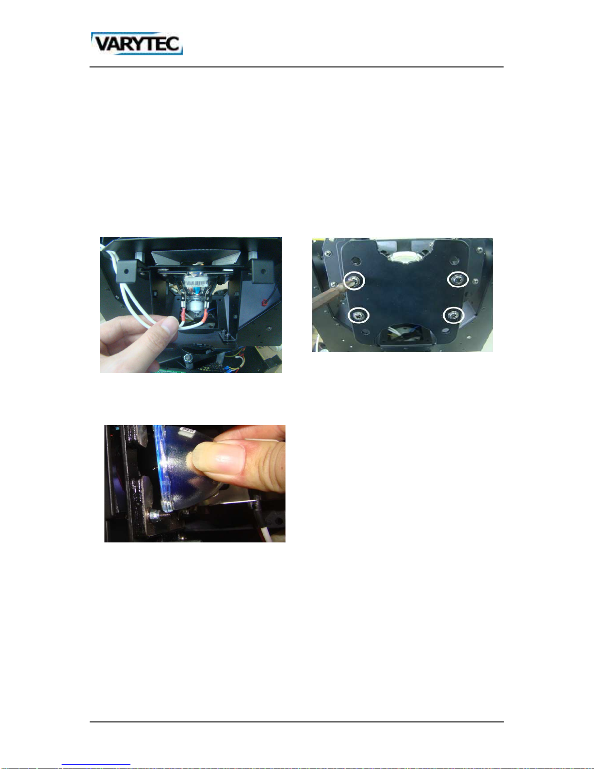
3.3.1. Changing the lamp
Important! If you change the lamp it is not allowed to touch the lamp with bare fingers. The body fat
layer remains in the lamp and could damaged it or brand.
1. Interrupt the current supply. Wait at least
20min before you open the device, so that the
old lamp can cool down.
2. Use a cross-tip screwdriver to open the cover
3. Loose the Lamp wires:
4. Loose the screws of the metal pieces:
5. Loose the screws of the lamp holders next to
the lamp and remove it:
6. Install the new lamp in reverse
Page 11

11 / 17
4. Control
4.1. Description of the display section
Every menu is controlled by the jogwheel on the right of the display.
Rotation changes the values if you push it you confirm the value. You can exit the menu with point of
menu EXIT; there you have to push the wheel again.
4.1.1. Structure of the menu
Main Menu Submenu 1 Submenu 2 Function SET Function description
DMX
Address
1-512 Address number set
Mode
Smal Simplify mode
Stan Standard mode
Exte Extended
Display
ShowReve
Natu Normal
Revl Reverse 180°
BrigSett 000-007 Brightness set
Backligh
60S Backlight close after delay 60s
Ligh Backlight light always
MenuBack
90S Menu back to main menu after delay 90s
Off Menu back not automatically
Return
Return
Feature
XY Setup
Xreverse
Off Pan scan normal
Open Pan scan reverse
Yreverse
Off Tilt scan normal
Open Tilt scan reverse
XY Speed
Fast Pan/Tilt fast speed
NORM Pan/Tilt normal
Solw Pan/Tilt slow
X Angle
360, 360 Pan angle 360°
540, 540 Pan angle 540°
630, 630 Pan angle 630°
XY Fback
Off Pan/Tilt optical sensor testing off
Open Pan/Tilt optical sensor testing on
Return
Return
Shortcut
Off Shortcut off for colors and gobos
Open Shortcut open for colors and gobos
FullColr
Off Half color function
Open Full color function
ReceMode
DMX, DMX Accept DMX
Wire Accept Wireless
Auto AutoRun
RunMode Slve Accept other signal control
Page 12

12 / 17
Muse Sound active
Auto Inside program run automatically
SigClear
Off keep signal data
Open clear signal data
Return
Return
LampSett
Default
Wink Lamp off
Ilum Lamp on
Control
Wink Lamp off by manual
Ilum Lamp on by manual
DmxLamp
Off Close other signal control the lamp
On open other signal control the lamp
LampTime 0000-9999 Lamp time
ClearTim
* Password input enter
Ilum Clear lamp time
LampStat
Wink Lamp off
Ilum Lamp on
Return
Return
InfoSee
WorkHour 0000-9999 working hours memo for connect power
Times 0000-9999 Open times memo
Fan1Rota 0000-9999 Fan rotation speed 1
Fan2Rota 0000-9999 Fan rotation speed 2
Version V0.0 Version
ChanLevel
Chan 00
-
Chan40
DMX value number
Return
Return
Control
Chan 00
-
Chan40
Control the channels
AssiTool
Factory
* Password input enter
Fold Recover factory set
Save Save factory set
Defaults
* Password input enter
Fold Recover to default
DMXReset
Off Close other signal control reset
Open Open other signal control reset
Redress * Password input enter
00-10 Set motors
Brightne
* Password input enter
TimeLimi 0000-9999 Open fixture time limit
TimsLimi 0000-9999 Fixture times limit
Passwor1 000-255 Revise password 1
Passwor2 000-255 Revise password 2
Passwor3 000-255 Revise password 3
Passwor4 000-255 Revise password 4
X Drivin 000-255 Pan main drive gear
X Driven 000-255 Pan slave drive gear
Page 13

13 / 17
Y Drivin 000-255 Tilt main drive gear
Y Driven 000-255 Tilt slave drive gear
LampPowe
Off Ballast earthed
total 5V, Open Ballast 5V
Y Angle 000-255 Tilt angle rotation set
Return 000-255 Return
Checksum 01-10 Check cabrilate data
Return
Return
Reset
Annu Cancel
Exec Reset
ExitMenu
Exit
4.2. DMX Chart
Channel
Value
from
Value
to
Description
1 PAN 0 255 Pan
2 PAN f 0 255 Pane fine
3 TILT 0 255 Tilt
4 TILT f 0 255 Tilt fine
5 PT Speed 0 255 PT speed from fast to slow
6 COLOR
0 4 Open white
5 9 Open white + Color 1
10 14 Color 1
15 19 Color 1 + Color 2
20 24 Color 2
25 29 Color 2 + Color 3
30 34 Color 3
35 39 Color 3 + Color 4
40 44 Color 4
45 49 Color 4 + Color 5
50 54 Color 5
55 59 Color 5 + Color 6
60 64 Color 6
65 69 Color 6 + Color 7
70 74 Color 7
75 79 Color 7 + Color 8
80 84 Color 8
85 89 Color 8 + Color 9
90 94 Color 9
95 99 Color 9 + Color 10
100 104 Color 10
105 109 Color 10 + Color 11
110 114 Color 11
Page 14

14 / 17
115 119 Color 11 + Color 12
120 124 Color 12
125 129 Color 12 + Color 13
130 134 Color 13
135 139 Color 13 + Color 14
140 144 Color 14
145 149 Color 14 + Weiß
150 200 Color rotation from slow to fast clockwise
201 204 Stop at any position
205 255 Color rotation from fast to slow counterclockwise
7 Gobo
0 4 Gobo offen
5 9 Gobo 1
10 14 Gobo 2
15 19 Gobo 3
20 24 Gobo 4
25 29 Gobo 5
30 34 Gobo 6
35 39 Gobo 7
40 44 Gobo 8
45 49 Gobo 9
50 54 Gobo 10
55 59 Gobo 11
60 64 Gobo 12
65 69 Gobo 13
70 74 Gobo 14
75 79 Gobo 15
80 84 Gobo 16
85 89 Gobo 17
90 94 Gobo 1 Shake
95 99 Gobo 2 Shake
100 104 Gobo 3 Shake
105 109 Gobo 4 Shake
110 114 Gobo 5 Shake
115 119 Gobo 6 Shake
120 124 Gobo 7 Shake
125 129 Gobo 8 Shake
130 134 Gobo 9 Shake
135 139 Gobo 10 Shake
140 144 Gobo 11 Shake
145 149 Gobo 12 Shake
150 154 Gobo 13 Shake
155 159 Gobo 14 Shake
160 164 Gobo 15 Shake
165 169 Gobo 16 Shake
170 174 Gobo 17 Shake
Page 15

15 / 17
175 210 Gobo wheel rotation slow to fast clockwise
211 224 Stop at any position
225 255 Gobo wheel rotation slow to fast counterclockwise
8 Shutter
0 19 Off
20 39 Open
40 59 Random strobe from slow to fast
60 79 Open
80 99 Ramp up from slow to fast
100 119 Open
120 139 Ramp down from slow to fast
140 249 Strobe standard from slow to fast
250 255 Open
9 Dimmer 0 255 Linear dimmer
10 Frost 0 255 Linear frost
11 Focus 0 255 Linear Focus
12 Prism
0 19 No effect
20 99 Indesing prism 360°
100 149 Prism rotation from slow to fast clockwise
150 159 Stop at any position
160 209 Prism rotation from slow to fast counterclockwise
210 255
Prism rotation clockwise/counterclockwise altering from
slow to fast
13 Reset
0 33 No function
34 36
Lamp off after 3 seconds when dimmer and shutter are at
255
37 79 No function
80 89
Lamp on after 3 seconds when dimmer and shutter are at
255
90 99 No function
100 109 Motor reset after 3 seconds
110 129 No function
130 139 Reset complete after 3 seconds
140 255 No function
14
Macros
functions
0 14 Open
15 32 Effect 1
33 46 Effect 2
47 63 Effect 3
64 79 Effect 4
80 95 Effect 5
96 110 Effect 6
111 125 Effect 7
126 143 Effect 8
144 159 Effect 9
160 175 Effect 10
176 191 Effect 11
Page 16

16 / 17
192 207 Effect 12
208 223 Effect 13
224 239 Effect 14
240 255 Effect 15
15 Speed 0 255 Speed for macro effects
Page 17

17 / 17
Importer:
B & K Braun GmbH
Industriestraße 2
D-76307 Karlsbad
www.bkbraun.com
info@bkbraun.com
 Loading...