

Page 1

Subject to modification! Updated 10/2017 Version 09
INSTRUCTION MANUAL
VARTA element
VARTA Storage GmbH
Page 2
2
Subject to modification! Updated 10/2017
The first part of this manual contains general
information on how to use the VARTA element
energy storage system.
Further information can be found in the
“Installation”, “Operation in the passwordprotected area” and “Maintenance” sections.
Congratulations!
You have opted for an energy storage system from VARTA Storage
GmbH! We are pleased that in doing so, you chose a durable
system for which we considered quality paramount. Please read
through these instructions carefully. They describe how to operate
and use the battery.
Have fun storing power!
Guidance for the qualified electrician
Page 3

Subject to modification! Updated 10/2017
3
Legal notice
Original Instruction Manual VARTA Storage GmbH
VARTA Storage GmbH
Nürnberger Straße 65
86720 Nördlingen
Germany
www.varta-storage.de
Tel.: 0049 9081 240 86 60
info@varta-storage.com
Technical service:
technical.service@varta-storage.com
Tel.: 0049 9081 240 86 44
Document number: OM_850_809
Updated 10/2017
Version 09
Page 4

4
Subject to modification! Updated 10/2017
Contents
General ........................................................................................... 12
1 Information about this manual ............................................ 12
1.1 Explanation of symbols .............................................. 12
1.1.1 Safety instructions .............................................. 12
1.1.2 Warning levels .................................................... 13
1.1.3 General safety signs ........................................... 14
1.1.4 Warning signs ..................................................... 15
2 Safety ................................................................................. 16
2.1 General information on safety .................................... 16
2.2 Intended use ............................................................... 18
2.3 Requirements regarding qualified electricians ........... 19
2.4 General hazard sources ............................................. 20
2.4.1 Danger of electrical voltage ................................ 20
2.4.2 Danger from water .............................................. 21
2.4.3 Danger from oxidising and corrosive
substances ......................................................... 21
2.4.4 Danger from heat ............................................... 22
2.4.5 Danger from misbehaviour ................................. 23
2.5 Safety devices ............................................................ 24
3 Function, scope of delivery and technical parameters ....... 25
3.1 Function ...................................................................... 25
3.2 Scope of delivery ........................................................ 26
3.3 Front view VARTA element ........................................ 28
3.4 System overview ........................................................ 29
Page 5

Subject to modification! Updated 10/2017
5
3.5 Rating plate ................................................................ 30
3.6 Technical parameters ................................................ 31
Operation ....................................................................................... 34
4 Switching on and off, web interface ................................... 34
4.1 Switching on and off .................................................. 35
4.2 LED ring indications ................................................... 36
4.3 Web interface ............................................................. 37
4.3.1 Access to the web interface ............................... 37
4.3.2 Information on the welcome page (Home) ........ 38
4.3.3 External relays (optional) ................................... 39
4.4 Portal (optional) ......................................................... 40
5 Maintenance and cleaning ................................................. 41
5.1 Maintenance work...................................................... 41
5.2 Cleaning ..................................................................... 42
6 Malfunction/event of damage ............................................ 43
6.1 Malfunction indicators ................................................ 44
6.1.1 Malfunction indicators of the LED ring ............... 44
6.1.2 Malfunction indicators on the web interface ...... 44
6.2 Behaviour in the event of damage ............................. 44
Installation...................................................................................... 46
7 Transport and storage ....................................................... 46
7.1 Transport ................................................................... 46
7.2 Transportation regulations and safety instructions .... 47
7.3 Packaging/transport control ....................................... 49
7.4 Storage ...................................................................... 51
Page 6

6
Subject to modification! Updated 10/2017
8 Assembly and installation ................................................... 52
8.1 Check the components ............................................... 52
8.2 Requirements for the installation location .................. 53
8.3 Installation location ..................................................... 54
8.3.1 Dimensions and features .................................... 54
8.3.2 Environmental conditions ................................... 55
8.3.3 Non-permissible locations and environmental
conditions ........................................................... 56
8.4 Warranty ..................................................................... 56
8.5 Warranty registration .................................................. 59
8.5.1 Warranty registration by the installation
engineer ............................................................. 59
8.5.2 Warranty registration by the customer ............... 64
8.6 Preparation of the electrical connection ..................... 68
8.6.1 Connections to the distributor box ...................... 70
8.6.2 Preparation of the AC port for the building
grid ..................................................................... 71
8.6.3 Current sensor .................................................... 74
8.7 Preparation of assembly ............................................. 76
8.8 Installing and connecting the storage cabinet ............ 77
8.9 Battery module assembly ........................................... 79
8.9.1 Opening the storage cabinet .............................. 80
8.9.2 Checking the battery modules ............................ 81
8.9.3 Behaviour in the event of damage ..................... 82
8.9.4 Installing and connecting battery modules ......... 84
8.9.5 Closing the storage cabinet ................................ 93
Page 7

Subject to modification! Updated 10/2017
7
8.10 Initial commissioning ................................................. 94
8.10.1 Checking the activation of the battery modules . 94
8.10.2 Switching on ...................................................... 94
8.10.3 Password entry .................................................. 96
8.10.4 Entering serial numbers of the battery modules 97
8.10.5 Portal connection ............................................... 99
8.10.6 Setting the grid parameters for GS protection . 100
8.10.7 Reboot ............................................................. 101
8.10.8 Checks on the welcome page ......................... 101
8.10.9 Checks on the "System" page ......................... 103
8.10.10 Exiting the password-protected area ........... 104
8.11 Quick Install ............................................................. 105
Operation in the password-protected area .................................. 108
9 The password-protected area.......................................... 108
9.1 Access to the web interface - password entry ......... 108
9.2 System ..................................................................... 109
9.3 Version ..................................................................... 109
9.4 Settings .................................................................... 110
9.4.1 Basic settings ................................................... 111
9.4.2 Network ............................................................ 112
9.4.3 Service settings ............................................... 113
9.4.4 Grid parameters for GS protection .................. 115
9.4.5 Reactive power compensation ........................ 117
9.5 Power limitation ....................................................... 124
9.6 Logging out .............................................................. 124
Page 8

8
Subject to modification! Updated 10/2017
Maintenance ................................................................................. 125
10 Maintenance basics ...................................................... 125
10.1 Safety instructions .................................................... 125
10.2 Scope of maintenance work ..................................... 127
11 Service and repair work ................................................ 128
11.1 Checking the storage cabinet from outside .............. 128
11.2 Checking the system parameters (Service) ............. 128
11.2.1 Checking the online status ............................... 129
11.2.2 Error lists .......................................................... 129
11.2.3 Checking the software version ......................... 130
11.2.4 Software update ............................................... 130
11.2.5 Air filter change: Resetting the time ................. 131
11.2.6 Checking the fan .............................................. 131
11.3 Checking the system parameters ............................. 133
11.3.1 Checking the current sensor values ................. 133
11.3.2 Checking the battery charger ........................... 134
11.3.3 Checking the battery modules .......................... 135
11.4 Service and repairs: Cabinet interior ........................ 136
11.4.1 Opening the cabinet ......................................... 137
11.4.2 Removing the battery inverter .......................... 138
11.4.3 Removing and installing the battery charger .... 138
11.4.4 Removing and installing battery modules ........ 142
11.4.5 Replacing/cleaning the air filter ........................ 144
11.4.6 Disassembling the storage cabinet cover ........ 144
11.4.7 Cleaning/replacing the fan ................................ 145
Page 9

Subject to modification! Updated 10/2017
9
11.5 Completion of service and repair work .................... 148
11.5.1 Checking the operating state ........................... 149
11.6 Cleaning ................................................................... 151
12 Malfunctions................................................................. 152
12.1 Malfunction indicators of the LED ring ..................... 152
12.2 Malfunction indicators on the web interface ............ 152
13 Disassembly and disposal ........................................... 153
13.1 Planning disassembly .............................................. 153
13.2 Disassembling ......................................................... 153
13.3 Disposal ................................................................... 154
14 Relocation .................................................................... 155
14.1 Planning a relocation ............................................... 155
14.2 Relocating ................................................................ 156
Page 10

10
Subject to modification! Updated 10/2017
About this manual
Please read this instruction manual carefully before beginning any
kind of work. It contains important information, in order to ensure
trouble-free functioning of the VARTA element energy storage
system.
The manual is structured in a way, so all work must be carried out
by a qualified electrician certified by VARTA Storage GmbH.
Storage of the manual
The instruction manual should be kept in close proximity to the
VARTA element and must be permanently available to all
individuals involved in working on the energy storage system.
If the owner changes, the instruction manual has to be handed
over.
Target groups
This manual is intended for different target groups:
End customers
Qualified electricians who are responsible for installation,
commissioning and maintenance.
Scope
This manual is part of the system and corresponds to the state-ofthe-art at the time of publication. This applies to the product VARTA
element in the expansion stages element 3, element 6, element 9,
or element 12 from serial number 125 XXXXXX onwards (rating
plate).
Page 11

Subject to modification! Updated 10/2017
11
i
Please keep in mind that this instruction manual
also refers to optional components, which are not
included in the scope of delivery as standard.
These parts or components are designated
"optional" in this manual. Just skip these parts of
the manual if your energy storage is not equipped
with them.
ATTENTION
Energy storage system switched off!
Potential damage to the battery module due
to deep discharge!
The energy storage system may be
switched off temporarily only for
maintenance purposes.
Limitation of liability
VARTA Storage GmbH accepts no liability for personal injuries,
material damage, damages at the product, as well as consequential
damages arising from non-observance of this manual, improper
use of the product, during repairs, opening of the storage cabinet
and other activities carried out by unqualified electricians who were
not certified by VARTA Storage GmbH. This limitation of liability
also applies to the use of non-approved spare parts, as well as
non-observance of the stated maintenance intervals.
It is prohibited to carry out unauthorised modifications or technical
changes at the product.
© VARTA Storage GmbH 2017
Special attention required
Page 12

12
Subject to modification! Updated 10/2017
i
Indicates tips for handling the device.
Signal word
Type and source of the hazard
Potential consequence(s) in case of nonobservance!
Measures and restraints for
avoiding the hazard.
General
1 Information about this manual
1.1 Explanation of symbols
This instruction manual uses the following types of safety
instructions and tips:
1.1.1 Safety instructions
In this manual, the safety instructions are structured as follows:
Table 1: Safety instructions
Page 13

Subject to modification! Updated 10/2017
13
General
Operation
Installation
Operation (Service)
Maintenance
Warning colour/signal
word
Consequences
warns of an immediately dangerous
situation, which might lead to death or
serious injuries and/or fire.
DANGER
warns of a potentially dangerous
situation, which might lead to death or
serious injuries and/or fire.
WARNING
warns of a potentially dangerous
situation, which might lead to minor
injuries and/or material damages.
CAUTION
warns of a potential situation, which might
lead to material and environmental
damages, and which might interrupt the
operating sequence.
ATTENTION
1.1.2 Warning levels
Signal word and warning colour indicate the warning level and give
immediate information on type and severity of the consequences if
measures for avoiding the hazard are not taken.
Table 2: Warning levels
Page 14

14
Subject to modification! Updated 10/2017
Symbol
Meaning
Prohibition symbols are circular, showing a
black pictogram on a white background
surrounded by a red edge with a crossbar.
Mandatory action symbols are circular,
showing a white symbol on a blue
background.
Warning signs are triangular, showing a black
symbol and edge on a yellow background.
Environmental regulations are information on
statutory requirements, which have to be
complied with, especially during disposal.
1.1.3 General safety signs
Table 3: Safety signs
Page 15

Subject to modification! Updated 10/2017
15
General
Operation
Installation
Operation (Service)
Maintenance
General warning sign
Warning of electrical voltage
Warning of oxidising substances
Warning of hand injuries
Warning of cut injuries
Warning of hazards due to batteries
Warning of non-observance of the
discharge time:
3 minutes!
1.1.4 Warning signs
Table 4: Warning signs
Page 16
16
Subject to modification! Updated 10/2017
WARNING
Non-observance of the safety instructions!
Improper use can lead to fatal injuries.
Prior to use, ensure that all protective
devices are functioning.
Read the instruction manual.
2 Safety
2.1 General information on safety
Any person being in charge of carrying out work at the system must
have read and understood this manual, especially the Chapter
Safety.
By observing the safety instructions and complying with the
instructed health and safety measures, the risk will be limited.
This manual cannot describe every conceivable situation, therefore
the currently applicable standards as well as the appropriate
regulations for industrial safety and health protection always have
priority.
Furthermore, the use of the energy storage system is associated
with residual risks under the following circumstances:
Installation and maintenance work is not performed
correctly.
Page 17

Subject to modification! Updated 10/2017
17
General
Operation
Installation
Operation (Service)
Maintenance
Installation and maintenance work is performed by
personnel who have not been trained and not been
instructed.
The safety instructions provided in this manual are not
observed.
All safety instructions have to be strictly followed, the observance is
for your safety. The device must not be modified in any way.
Page 18

18
Subject to modification! Updated 10/2017
WARNING
Possible mortal danger due to wrong use!
Possible mortal danger
The device accommodates parts
carrying hazardous voltages. Contact
with these parts can be fatal.
Any usage beyond or other than the
intended use of the energy storage
system or individual parts of it might
lead to life threatening situations.
Do not use VARTA element:
for mobile use at land, water or air.
for use at medical devices.
2.2 Intended use
VARTA element as well as the components thereof, is built to stateof-the-art technology and to product-specific standards. This
product is designed for storing electricity from renewable energy
generating plants, such as photovoltaic systems or other energy
sources. Any other use must be agreed in consultation with the
manufacturer and the local energy supplier.
Page 19

Subject to modification! Updated 10/2017
19
General
Operation
Installation
Operation (Service)
Maintenance
WARNING
Insufficient qualification of the electrician!
Personal injuries and material damage!
Work at the VARTA element system
(e.g. installation and maintenance
work) may only be carried out by
qualified electricians who are certified
by VARTA Storage GmbH!
i
The “Installation”, “Operation in the password-
protected area” and “Maintenance” sections
contain further information for qualified
electricians.
2.3 Requirements regarding qualified electricians
Page 20

20
Subject to modification! Updated 10/2017
DANGER
Contact with electrical voltage!
Risk of fatal injury from electric shock!
Keep the energy storage system
always closed.
Pay attention to damages of the
electrical equipment! Eliminate defects
immediately!
Only the electrician is allowed to open
the energy storage system when it is
switched off.
Respect the waiting times.
2.4 General hazard sources
If the following instructions for handling the device are not
observed, this might lead to personal injury or material damage at
the device, for which VARTA Storage GmbH will accept no liability.
2.4.1 Danger of electrical voltage
Page 21

Subject to modification! Updated 10/2017
21
General
Operation
Installation
Operation (Service)
Maintenance
WARNING
Entry of water into electrical systems!
Possible mortal danger and material damage!
Do not use water for cleaning the
energy storage system.
Never put down containers with fluids
(beverage containers and the like) on
electrical systems.
The relative humidity inside the room
must not exceed 80%.
WARNING
Storage and use of oxidising and
corrosive substances
Increases the risk of fire and the risk of
electric shocks.
Store the above mentioned substances
only at places that are intended for
them.
Do not clean the system with agents
containing acid, lye or solvents.
2.4.2 Danger from water
2.4.3 Danger from oxidising and corrosive substances
Page 22

22
Subject to modification! Updated 10/2017
ATTENTION
Insufficient ventilation of the system!
Overheating of the system possible!
Keep the ventilation openings clear.
Ensure sufficient ventilation.
ATTENTION
Heat input due to direct sunlight or
devices emitting heat!
Overheating and damage of the system
possible!
Protect the system against direct
sunlight.
Do not use fan heaters or the like near
the system.
2.4.4 Danger from heat
Page 23
Subject to modification! Updated 10/2017
23
General
Operation
Installation
Operation (Service)
Maintenance
ATTENTION
Energy storage system switched off!
Potential damage to the battery module due
to deep discharge!
The energy storage system may be
switched off temporarily only for
maintenance purposes.
ATTENTION
Objects on the system!
Risk of injury due to falling objects, and the
system might be damaged!
Do not put any objects on the energy
storage system.
ATTENTION
Blocked access!
In the event of damage, the system cannot be
switched off!
The access to the energy storage
system must always be ensured.
2.4.5 Danger from misbehaviour
Page 24

24
Subject to modification! Updated 10/2017
WARNING
Defective safety devices!
Possible mortal danger!
Safety devices must not be damaged,
modified, removed, or
decommissioned.
The proper functioning of the safety
devices must be tested by qualified
electricians who are certified by VARTA
Storage GmbH after completion of
installation and commissioning.
2.5 Safety devices
The VARTA element energy storage system has multiple safety
devices. Including grid and system protection to VDE-AR-N 4105,
closed electrical operating area, overtemperature cutout and a door
contact switch. This switches off the system if an attempt is made
to open the storage cabinet before it has been de-energised.
Furthermore it is recommended to install a smoke detector in the
installation room of the VARTA element.
Page 25

Subject to modification! Updated 10/2017
25
General
Operation
Installation
Operation (Service)
Maintenance
3 Function, scope of delivery and technical
parameters
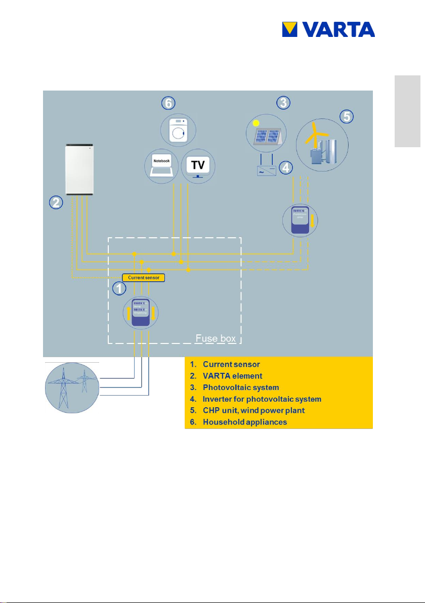
3.1 Function
The VARTA element battery storage system is a storage system for
operation in a 3-phase building grid, which offers the option of
connecting a separate grid-connected photovoltaic system. This
must be a generating unit which supplies to surplus rather than to
full feed. There is also provision for storing renewable energy, for
example from small wind turbines or other CHP system energy
sources.
The VARTA element system is used to increase the share of
private consumption and the efficiency of a photovoltaic system. If
the photovoltaic system generates more electricity than
immediately needed, it can be stored temporarily in the energy
storage system. The electricity will be fed into the building grid, as
soon as the consumption rises again above the electricity
generated by the photovoltaic system.
The VARTA element system is integrated into the building grid as a
3-phase AC connection and operates independently of the
photovoltaic system. A current sensor controls the charge and
discharge processes of the energy storage system. It is mounted in
the fuse box, directly behind the consumption/feed-in meter, and
measures all incoming and outgoing currents.
If the current sensor measures outgoing currents in case of
available free charge capacity of the energy storage system, it will
be charged. During the process, the battery inverter inside the
VARTA element system converts AC to DC and charges the
battery modules. If the maximum charge capacity is reached, or the
solar electricity exceeds the maximum charging current, the surplus
solar electricity is fed into the public grid. If the photovoltaic system
Page 26

26
Subject to modification! Updated 10/2017
is not able to cover the current electricity demand inside the
building, the current sensor measures incoming currents. As a
result, the energy storage system gives output into the building
grid, in order to minimise the external electricity consumption and
the associated costs.
Before installing the VARTA element energy storage system, the
appropriate energy provider has to be asked, whether it is
necessary to register the system.
3.2 Scope of delivery
The VARTA element energy storage system consists of:
Storage cabinet with integrated energy and battery
management
Battery module(s)
Battery inverter
Expansion stage element 3:
1 x Battery charger,
1 x Communication cable set,
1 x Power cable
Expansion stage element 6:
1 x Battery charger,
1 x Communication cable set,
1 x Power cable
Expansion stage element 9:
2 x Battery charger,
2 x Communication cable set,
2 x Power cable
Page 27

Subject to modification! Updated 10/2017
27
General
Operation
Installation
Operation (Service)
Maintenance
Expansion stage element 12:
2 x Battery charger,
2 x Communication cable set,
2 x Power cable
Extra items:
Current sensor (50 A) with sensor board,
20 m sensor cable RJ11,
1 x AC connector,
8 x mounting screws for battery module(s),
Instruction Manual
Customer folder
accompanying letter,
return envelope,
commissioning report,
service booklet,
warranty records,
Online Portal Agreement
Page 28
28
Subject to modification! Updated 10/2017
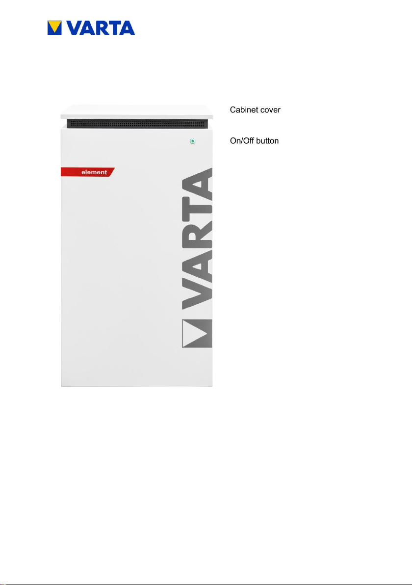
3.3 Front view VARTA element
Figure 1: Front view VARTA element
Page 29
Subject to modification! Updated 10/2017
29
General
Operation
Installation
Operation (Service)
Maintenance
3.4 System overview
Figure 2: System overview VARTA element
Page 30

30
Subject to modification! Updated 10/2017
Figure 3: Rating plate VARTA element
Figure 4: Cryptocode
3.5 Rating plate
Page 31

Subject to modification! Updated 10/2017
31
General
Operation
Installation
Operation (Service)
Maintenance
EXPANSION STAGE ELEMENT 3
Nominal capacity
AC charge power
AC discharge power
Battery inverter structure
Dimensions in mm (W x H x D)
Weight (incl. battery module)
Installation location
Grid connection
Make current
Maximum output residual current
Internal consumption
optimisation
Power measurement
System transport
Packaging in mm (W x H x D)
Grid system fusing
3.3 kWh
1.8 kW
1.6 kW
without isolation transformer
600 x 1,176 x 500
95 kg
inside the building
400 V AC, 3-phase, 50 Hz
< max. operating current
for input and output
max. 6 A for 100 μs
3-phase, regulated
3-phase, via current sensor
vertical on a pallet
700 x 1,325 x 600
16 A (B-character)
EXPANSION STAGE ELEMENT 6
Nominal capacity
AC charge power
AC discharge power
Battery inverter structure
Dimensions in mm (W x H x D)
Weight (incl. battery modules)
Installation location
Grid connection
Make current
Maximum output residual current
Internal consumption
optimisation
Power measurement
System transport
Packaging in mm (W x H x D)
Grid system fusing
6.5 kWh
2.2 kW
1.8 kW
without isolation transformer
600 x 1,176 x 500
115 kg
inside the building
400 V AC, 3-phase, 50 Hz
< max. operating current
for input and output
max. 6 A for 100 μs
3-phase, regulated
3-phase, via current sensor
vertical on a pallet
700 x 1,325 x 600
16 A (B-character)
3.6 Technical parameters
Table 5: Technical parameters – expansion stage element 3
Table 6: Technical parameters – expansion stage element 6
Page 32

32
Subject to modification! Updated 10/2017
EXPANSION STAGE ELEMENT 9
Nominal capacity
AC charge power
AC discharge power
Battery inverter structure
Dimensions in mm (W x H x D)
Weight (incl. battery modules)
Installation location
Grid connection
Make current
Maximum output residual current
Internal consumption
optimisation
Power measurement
System transport
Packaging in mm (W x H x D)
Grid system fusing
9.8 kWh
3.4 kW
3.0 kW
without isolation transformer
600 x 1,176 x 500
145 kg
inside the building
400 V AC, 3-phase, 50 Hz
< max. operating current
for input and output
max. 6 A for 100 μs
3-phase, regulated
3-phase, via current sensor
vertical on a pallet
700 x 1,325 x 600
16 A (B-character)
EXPANSION STAGE ELEMENT 12
Nominal capacity
AC charge power
AC discharge power
Battery inverter structure
Dimensions in mm (W x H x D)
Weight (incl. battery modules)
Installation location
Grid connection
Make current
Maximum output residual current
Internal consumption
optimisation
Power measurement
System transport
Packaging in mm (W x H x D)
Grid system fusing
13 kWh
4 kW
3.7 kW
without isolation transformer
600 x 1,176 x 500
165 kg
inside the building
400 V AC, 3-phase, 50 Hz
< max. operating current
for input and output
max. 6 A for 100 μs
3-phase, regulated
3-phase, via current sensor
vertical on a pallet
700 x 1,325 x 600
16 A (B-character)
Table 7: Technical parameters – expansion stage element 9
Table 8: Technical parameters – expansion stage element 12
Page 33

Subject to modification! Updated 10/2017
33
General
Operation
Installation
Operation (Service)
Maintenance
BATTERY MODULE (VKB 56461701100)
Electrochemical cell
Nominal module capacity
Discharge depth
Useful module capacity
Connection
Cell monitoring
Dimensions in mm (W x H x D)
Weight
Packaging in mm (W x H x D)
Li-ion
3.3 kWh
90%
3.0 kWh
touch safe
integrated
445 x 110 x 339
25 kg
800 x 460 x 600
BATTERY MODULE (VKB 56462701100)
Electrochemical cell
Nominal module capacity
Discharge depth
Useful module capacity
Connection
Cell monitoring
Dimensions in mm (W x H x D)
Weight
Packaging in mm (W x H x D)
Li-ion
6.5 kWh
90%
5.9 kWh
touch safe
integrated
445 x 110 x 587
45 kg
800 x 460 x 600
ENVIRONMENTAL RATING DATA
Environmental category
Classification of wet rooms
Degree of contamination
Ingress protection
Ambient temperature
Relative humidity
Max. altitude
Overvoltage category
Protection class
Air-conditioned indoors*
No wet rooms allowed
2
IP22
+5 °C to +30 °C
< 80%
2000 m ASL
III
1
*The energy storage system is completely enclosed by a building or housing. This protects the
energy storage system against sunlight, dust and other external influences. Additionally, the
building or housing is air-conditioned with regard to temperature, air humidity and air filtering.
Table 9: Technical parameters – battery modules
Table 10: Technical parameters – environmental rating data
Page 34

34
Subject to modification! Updated 10/2017
DANGER
Contact with electrical voltage!
Risk of fatal injury from electric shock!
Keep the energy storage system
always closed.
Pay attention to damages of the
electrical equipment!
Eliminate defects immediately!
Only the electrician is allowed to open
the energy storage system when it is
switched off.
Respect the waiting times.
ATTENTION
Energy storage system switched off!
Potential damage to the battery module due
to deep discharge!
The energy storage system may be
switched off temporarily only for
maintenance purposes.
Operation
4 Switching on and off, web interface
Page 35

Subject to modification! Updated 10/2017
35
General
Operation
Installation
Operation (Service)
Maintenance
The On/Off button on the front of the cabinet is pressed by the
certified installation engineer during commissioning and for service
work. In case of damage (see Chapter 6.2), the system can be
shut-down using the On/Off button.
Figure 5: On/Off button with LED ring
4.1 Switching on and off
Page 36

36
Subject to modification! Updated 10/2017
LED ring
colour
LED action
Operating state
Green
Flashes every second
(approx. 90 s)
System check
Green
Steady light
Ready
Green
Flashes every 3 s
Standby
Green
Pulses with increasing
intensity
Charge
Green
Pulses with decreasing
intensity
Discharge
Green
-red
Flashes
Update
Red
Steady light
Error*
Red
Flashes every second
Current sensor
check failed
*The i-button on the welcome page of the web interface displays
information about current errors (see Chapter 4.3.2).
4.2 LED ring indications
The LED ring at the On/Off button indicates the states and events
which occur while the energy storage system is in operation.
Table 11: LED ring indications at the On/Off button
Page 37

Subject to modification! Updated 10/2017
37
General
Operation
Installation
Operation (Service)
Maintenance
i
Access to the web interface might require
the browser to be refreshed.
4.3 Web interface
The web interface offers the option of configuring settings, as well
as monitoring and controlling the energy storage system functions.
4.3.1 Access to the web interface
To access the web interface, you will need the serial number of the
energy storage system. The serial number can be found on the
rating plate on the outside of the cabinet (top). See Figure 3: Rating
plate VARTA element
Connect your storage cabinet to the router of your home network
by means of the network cable. The port (RJ45 socket) is located at
the rear of the cabinet. See Figure 16.
Enter the serial number of the energy storage system
behind http://varta in the address line of your browser.
e.g.: http://varta125023456
The welcome page of the web interface will appear.
The web interface is factory-tested with the following browsers:
Firefox, Internet Explorer, Chrome and Opera.
Page 38

38
Subject to modification! Updated 10/2017
Figure 6: Web interface: Welcome page
4.3.2 Information on the welcome page (Home)
The welcome page provides an overview of the current power
values and the states of the energy storage system:
(1) Charge power of the battery inverter in watt (W):
The energy storage system is charged with this power
(power of the generating units, e.g. PV system, CHP,
minus the direct internal consumption).
(2) Discharge power of the battery inverter in watt (W):
The energy storage system is discharged with this power.
(3) Power of the grid supply/grid draw (W): The power
supplied into the public grid or drawn from the public grid
is displayed.
Page 39

Subject to modification! Updated 10/2017
39
General
Operation
Installation
Operation (Service)
Maintenance
(4) Operating state of the energy storage system: The
operating state, e.g. standby, charging, error is displayed.
(5) The charging state of the energy storage system in
%: The charge level of the energy storage system is
displayed.
(6) WWW: Indicates whether the energy storage system is
connected to the VARTA server (green = online, red =
offline).
(7) Info button (i): Displays information about the storage
system, e.g. IP address, energy counter, or the most
recent grid faults.
To see further explanations, move the cursor over the symbols.
4.3.3 External relays (optional)
Via the web interface, up to four external relays can be individually
programmed for controlling special functions, such as switching
consumers or generating units on/off. Clicking the Ext. relay button
shows the corresponding page.
A download available from www.varta-storage.com provides further
information.
Page 40

40
Subject to modification! Updated 10/2017
i
The data displayed on the VARTA Storage
portal cannot be used for billing purposes.
4.4 Portal (optional)
The www.varta-storage-portal.com portal serves to monitor and
visualise energy storage systems. To ensure continuous data
transmission, the Internet connection must not be interrupted for
longer than five days.
Access to the portal is activated if the option "I wish to use the
VARTA Storage Online Portal", which appears during online login
to the storage system, has been checked. A download is available
from www.varta-storage.com for the online login to the storage
system and for using the portal (see Chapter 8.5 Warranty
registration).
Alternatively, you can tick the "I wish to use the VARTA Storage
Online Portal" box on the warranty card, which you return to
VARTA Storage GmbH.
Use of the Online Portal is free-of-charge. The Internet connection
costs must be borne by the customer. However, there is no
entitlement to access the portal (see the Terms and Conditions for
the Online Portal in the download area).
Page 41

Subject to modification! Updated 10/2017
41
General
Operation
Installation
Operation (Service)
Maintenance
WARNING
Improper execution of maintenance and
cleaning work
Possible mortal danger!
Ensure that only qualified electricians
certified by VARTA Storage GmbH
carry out maintenance and cleaning
work!
Only original parts are to be used for
maintenance work.
5 Maintenance and cleaning
5.1 Maintenance work
Maintenance of the energy storage system includes:
Service (= inspection and maintenance)
Repair and technical improvements and any additions
To maintain the warranty entitlement (outside of Germany, Austria
and Switzerland: to safeguard any warranty claims), the first
service must be carried out within two years of the installation date.
Subsequent servicing must be at three year intervals.
Page 42

42
Subject to modification! Updated 10/2017
i
Retain the service booklet together with
the instruction manual.
WARNING
Entry of water into electrical systems!
Possible mortal danger!
Do not use water for cleaning the
energy storage system
Never put down containers with fluids
(beverage containers and the like) on
electrical systems.
Cleaning agents
Do not use any cleaning agents containing acid, lye or
solvents!
Cleaning the outside of the housing
clean with a vacuum cleaner.
wipe with a damp, not wet, cloth.
The extent of the maintenance work is described in the Chapter
Maintenance.
5.2 Cleaning
Page 43

Subject to modification! Updated 10/2017
43
General
Operation
Installation
Operation (Service)
Maintenance
WARNING
Improper elimination of malfunctions!
Possible mortal danger!
Ensure that only qualified electricians
certified by VARTA Storage GmbH
carry out work at the energy storage
system!
i
In case of a malfunction, contact the qualified
electrician.
6 Malfunction/event of damage
Page 44

44
Subject to modification! Updated 10/2017
WARNING
Improper handling in case of fire and
flooding!
Possible mortal danger!
If possible, switch off the system and
disconnect the fuses.
Leave the hazard zone.
In case of fire, call the fire brigade
immediately.
Inform the fire brigade about the
lithium-ion batteries inside the energy
storage system.
6.1 Malfunction indicators
6.1.1 Malfunction indicators of the LED ring
The LED ring of the On/Off button on the front of the cabinet
indicates malfunctions. See Table 11 in Chapter 4.2.
6.1.2 Malfunction indicators on the web interface
Malfunctions are displayed on the welcome page of the web
interface.
To do this, click on the i icon.
A window will open. Any pending system errors and the
previous five grid faults can be read from this window.
6.2 Behaviour in the event of damage
Page 45

Subject to modification! Updated 10/2017
45
General
Operation
Installation
Operation (Service)
Maintenance
i
In the event of a fire or flooding, prudent
behaviour can limit the damage.
WARNING
Damaged battery module due to technical
defect!
Pungent smell
Avoid contact with possibly leaking
fluid!
Avoid contact with possibly escaping
vapours!
If possible, switch off the system and
disconnect the fuses.
Avoid sparks and open flames.
Ventilate the installation room.
In case of a malfunction, contact the
qualified electrician.
Page 46

46
Subject to modification! Updated 10/2017
This section is intended for the qualified
electrician.
Installation
7 Transport and storage
7.1 Transport
Lithium-ion batteries are hazardous goods. The battery modules
are constructed and tested in a way, so they are allowed to be
transported up to a total weight of 333 kg by complying with the
conditions of ADR 1.1.3.6 (transport not subject to labelling, as long
as there are no other hazardous goods on or inside the vehicle).
The other requirements of GGVSEB (ordinance on the national and
international carriage of hazardous goods by road, rail, and inland
waterways) and ADR (Agreement on Dangerous Goods by Road)
also have to be fulfilled. Delivery is made in tested hazardous
goods packaging.
Lithium-ion batteries were successfully tested according to
UN 38.3 transport test (UN Manual of Tests and Criteria, Part III,
subsection 38.3) and have passed.
The storage cabinet is packaged separately from the battery
modules.
Page 47

Subject to modification! Updated 10/2017
47
General
Operation
Installation
Operation (Service)
Maintenance
WARNING
Improper transport due to lack of
professional knowledge.
Possible mortal danger and material damage!
The transportation of the energy storage
system and its components is only
allowed to be carried out by the
manufacturer and the electricians
qualified and certified by him.
Be prudent during transport.
Adhere to the transportation regulations!
The housing and the battery module
must not be temporarily stored in the transport vehicle.
the energy storage system must not be transported if a
battery module has already been installed.
driver or co-driver are not allowed to open the outer
packaging of a battery module.
instructions
7.2 Transportation regulations and safety
Page 48

48
Subject to modification! Updated 10/2017
The housing and the battery module
a tested ABC fire extinguisher with a minimum capacity of
2 kg has to be carried along.
observe the symbols on the packaging.
Transport the parts only in enclosed vehicles.
the load has to be properly secured.
transport the battery module only in its intended transport
packaging.
adhere to the requirements according to GGVSEB and
ADR!
Use your personal protective equipment.
This reduces the risk of injuries during the mechanical work.
WARNING
Components are heavy!
This might lead to overburdened
intervertebral discs, bruises and crushings!
Carry out the work described in this
chapter with 2 persons or suitable
equipment.
Page 49

Subject to modification! Updated 10/2017
49
General
Operation
Installation
Operation (Service)
Maintenance
i
When exchanging a battery module, request
new hazardous goods packaging if required,
pack the battery module and have it picked up
by the supplier.
DANGER
Installation of damaged components!
Mortal danger!
Do not accept clearly damaged
packaging.
Contact VARTA Storage GmbH!
7.3 Packaging/transport control
Storage cabinet and battery module (individually packaged) are
delivered in separate and tested packaging units on pallets. The
disposal of the packaging will be taken over by the installation
engineer. Please examine the deliveries on completeness and
damages:
If damages are already visible at the packaging, please
note this down on the delivery documents and have the
driver confirm this by signature.
If the packaging is severely damaged, reject the deliveries.
In order to identify improper handling during transport, a
ShockWatch® sticker is attached to the outside of the cardboard
packaging of the storage cabinet. If the shock indicator is red, the
consignment has been exposed to strong vibrations.
Page 50

50
Subject to modification! Updated 10/2017
i
Remove the packaging not until immediately
before the installation. This avoids damages.
Keep the packaging material, so the system
can be properly packaged in case of a
subsequent transport (relocation).
The storage cabinet may be damaged.
Do not reject the consignment!
Enter "Indicator red" on the transport note.
Leave all parts packed in the original packaging and
request a damage inspection by the shipper immediately.
Figure 7: ShockWatch®sticker
Page 51

Subject to modification! Updated 10/2017
51
General
Operation
Installation
Operation (Service)
Maintenance
WARNING
Entry of water into electrical systems!
Short-circuit and corrosion due to condensation!
Adhere to the storage conditions.
The housing and the battery module
must not be temporarily stored in the transport vehicle.
must not be stored outdoors.
avoid sudden temperature changes.
The housing and the battery module
are to be stored dry, at a humidity of < 80%.
are to be stored at a temperature of 5 30 °C
(optimum: +18 °C).
ATTENTION
Material damage due to overstorage!
Deep discharge of the battery module!
Adhere to the storage conditions.
The battery module
must be commissioned by the manufacturer or a qualified
electrician certified by VARTA Storage GmbH within
eleven weeks of being delivered.
7.4 Storage
Page 52

52
Subject to modification! Updated 10/2017
This section is intended for the
qualified electrician.
WARNING
Entry of water into electrical systems!
Short-circuit and corrosion due to condensation!
Start the assembly not until the
components have room temperature.
WARNING
Installation of damaged components!
Possible mortal danger!
Check all components on visible
damages.
Do not install damaged components.
Contact VARTA Storage GmbH.
8 Assembly and installation
8.1 Check the components
Page 53

Subject to modification! Updated 10/2017
53
General
Operation
Installation
Operation (Service)
Maintenance
This section is intended for the
qualified electrician.
WARNING
Entry of water into electrical systems!
Mortal danger from electric shock!
Install the storage cabinet only inside
buildings.
Observe all requirements for the
installation location.
CAUTION
Personal injury and material damage due
to wrong installation and lack of space!
Crush injuries of limbs!
Place the cabinet, so a safe installation,
operation, maintenance and
disassembly are possible when used
properly.
8.2 Requirements for the installation location
Page 54

54
Subject to modification! Updated 10/2017
8.3 Installation location
The following dimensions and framework conditions have to be
complied with at the installation location.
8.3.1 Dimensions and features
For the room, in which the VARTA element will be installed, a
volume of at least 30 m³ is recommended. A horizontal, even floor
with a minimum surface of 70 cm x 55 cm (width x depth). The floor
must be able to take the load.
Weight of the energy storage system Chapter 3.6 Technical
parameters.
If necessary, have the statics tested.
The ground, the adjacent walls and ceiling must not
consist of heat-sensitive material.
The distance to the adjacent installations must be approx. 5 cm to
the right and approx. 10 cm to the left. A clear space of approx. 120
cm depth is required in front of the device, in order to carry out
installation and maintenance work via the front door. In order to
secure the means of escape, doors must not swing into this clear
space.
Page 55

Subject to modification! Updated 10/2017
55
General
Operation
Installation
Operation (Service)
Maintenance
Sufficient rodent protection must be provided.
Smoking is not allowed at the installation
location!
The screws for opening the storage cabinet on the left next to the
front door must be accessible.
A minimum clearance of 30 cm must be left above the storage
cabinet. The distance between the wall and the rear of the cabinet
must remain free to enable cooling air to escape from the device
unhindered.
8.3.2 Environmental conditions
The installation location must match a pollution degree 2.
A continuous air exchange, possibly via forced ventilation, e.g.
window, air-conditioning system, ventilation or the like, has always
to be ensured. The distance to the ventilation must be at least
100 cm.
The room temperature always has to be between 5 30 °C
(optimum +18 °C), the relative humidity must be < 80%.
Recommendation: well ventilated room without external heat
sources
Page 56

56
Subject to modification! Updated 10/2017
8.3.3 Non-permissible locations and environmental
conditions
Altitudes above 2,000 metres,
Garages, carports or other places, at which the environmental
conditions are not complied with.
Locations:
with explosive atmosphere
at which flammable or oxidising substances are stored
Wet rooms
with high fluctuations of the ambient temperature
with direct sunlight
with a humidity above 80% and condensation
in which the temperature might be below the freezing point
in which salty humidity might enter
with ammonia containing environment
8.4 Warranty
For the warranty to be effective (to safeguard any warranty claims
outside Germany, Austria and Switzerland), VARTA Storage GmbH
must be in possession of the following data:
Commissioning report (including date of commissioning)
Serial number (SN number) of the VARTA system.
The ID label (rating plate) of the system is affixed inside
the storage cabinet.
Serial number(s) of the battery module/battery modules.
The ID label of the battery module is enclosed in the
packaging.
The installation engineer enters these data in the VARTA Storage
GmbH installation engineer portal. Within four weeks of the
Page 57

Subject to modification! Updated 10/2017
57
General
Operation
Installation
Operation (Service)
Maintenance
Figure 8: ID label (rating plate) of the system
(inside the storage cabinet)
address, email address, telephone number) at www.varta-storageportal.com and enter the serial number (SN number) of the VARTA
element system and the activation code. The installation engineer
can also register the data, subject to the customer's consent.
The activation code label (Unlock Code) is affixed to the
inside of the storage cabinet door. This label is provided
for the customer's personal documents.
As an alternative to this procedure, the completed and signed
warranty records (commissioning report and warranty card,
together with the affixed ID label for the VARTA system and battery
modules) can be sent to VARTA Storage GmbH within four weeks
of the installation date.
installation date, the customer must register their data (name,
Page 58

58
Subject to modification! Updated 10/2017
Figure 9: ID label of the battery module (example)
Figure 10: Activation code label (example)
Page 59

Subject to modification! Updated 10/2017
59
General
Operation
Installation
Operation (Service)
Maintenance
8.5 Warranty registration
This online-based warranty registration consists of two parts:
Part 1: Registration of the energy storage system by the installation
engineer incl. commissioning report (Chapter 8.5.1)
Part 2: Warranty registration by the end customer incl. registration
for the web portal (Chapter 8.5.2)
8.5.1 Warranty registration by the installation engineer
Open page www.varta-storage.com
Change to "energy storage systems"
Registration in the B2B area with login and password
On the welcome page, click on "Start VARTA-Portal"
Change to "energy storage registration"
Entering the data for the battery storage:
Initial installation/retrofit
Date
Installation engineer
Serial number
Activation code
The system's serial number and the activation code can be found
on the stickers on the inside of the battery cabinet.
Page 60

60
Subject to modification! Updated 10/2017
i
If the storage is connected to the Internet, the
serial number or the serial numbers of the
installed battery modules will be transmitted
automatically.
The battery module has to be registered at the
latest 11 weeks after delivery.
Call up the next screen "battery modules" with "next".
Enter the serial number(s).
NOTE: This applies to all battery modules which have not yet been
registered.
Page 61

Subject to modification! Updated 10/2017
61
General
Operation
Installation
Operation (Service)
Maintenance
Call up the next screen "customer data" with "next".
Determine whether the customer agrees that the
installation engineer completes the following fields and
transmits them to VARTA Storage GmbH.
If "Yes", continue with the next screen
If "No", the screen "customer data" will be skipped. In this
case, the end customer has to enter these data in the 2nd
part of the warranty registration himself.
Entering the customer data.
Mandatory fields are marked with an *.
Call up the next screen "commissioning" with "next".
Page 62

62
Subject to modification! Updated 10/2017
Details of the commissioning report
Page 63

Subject to modification! Updated 10/2017
63
General
Operation
Installation
Operation (Service)
Maintenance
Confirmation of the registration
Completion of the registration with "close"
These data can be viewed in the B2B area:
Open under "warranty registration" or save as a PDF.
Page 64

64
Subject to modification! Updated 10/2017
8.5.2 Warranty registration by the customer
Open page www.varta-storage.com
Change to "energy storage systems"
Registration in the portal
Under: "No access yet? Register now"
with serial number and activation code.
Enter the following details
Battery storage,
Contact data
Declaration for contacting via telephone
Declaration for the use of the online services plus
contacting via telephone
Cancellation right information
Voluntary consents of the customer
Page 65

Subject to modification! Updated 10/2017
65
General
Operation
Installation
Operation (Service)
Maintenance
Click the button "Send registration".
Page 66

66
Subject to modification! Updated 10/2017
After completion of the entries, the details of the warranty
registration are displayed.
Correct the entries or send the registration now.
Page 67

Subject to modification! Updated 10/2017
67
General
Operation
Installation
Operation (Service)
Maintenance
Confirmation with the warranty registration as a PDF.
Final screen with the warranty documents as a PDF.
After registration, the customer receives an email with the access
data.
Alternatively, the customer can register with the enclosed warranty
card (sheet 1, 2 and 4).
Page 68

68
Subject to modification! Updated 10/2017
This section is intended for the
qualified electrician.
Use your personal protective equipment.
This reduces the risk of injuries during the mechanical work.
Observe the safety rules!
Disconnect
Lockout
Check for absence of voltage
Before connecting up the power supply, make sure
that no persons are in the hazard zone.
8.6 Preparation of the electrical connection
Page 69

Subject to modification! Updated 10/2017
69
General
Operation
Installation
Operation (Service)
Maintenance
WARNING
Improper installation!
Personal injury and material damage
Design the fuse ahead of the energy
storage system with three poles!
It must fulfil the requirements of a
separator.
Fuse the device connection at the
energy storage system with a 16 A fuse
type B.
Observe the disconnect conditions in
accordance with VDE 0100-410.
Never connect the energy storage
system without a PE and N connection!
A suitable separator must be installed
between power grid and customer
system (e.g. selective automatic cut-out
'SAC'), which can be used for all-poles
disconnection of the customer system
from the grid during maintenance work.
Observe the specified conductor crosssections!
For the position of the separators, see the connection
diagrams (Figures 1a/1b and 2a/2b) in the Appendix.
Page 70

70
Subject to modification! Updated 10/2017
i
1. Do not allow any mechanical load on the
sensor cable.
2. In order to minimise losses, the wiring
section between storage and connection
should not be longer than 20 m.
8.6.1 Connections to the distributor box
The following connections must be prepared:
Device connection: 5 x 1.5 - 2.5 mm²
Sensor cable: RJ12
LAN connection
Page 71

Subject to modification! Updated 10/2017
71
General
Operation
Installation
Operation (Service)
Maintenance
Figure 11: Stripping cables
i
A flexible plastic-sheathed cable facilitates
assembly work.
8.6.2 Preparation of the AC port for the building grid
To connect to the building grid, the 5-wire AC cable must be
connected to the supplied AC connector.
Strip the cable 40 mm at the end.
The PE conductor must be 5 mm longer than the other
four conductors (L1, L2, L3, N). Shorten these conductors
accordingly.
Strip the wires for the building connection approx. 8 mm at
the ends.
Ferrules must be used for fine-stranded conductors.
Screw off the union nut of the strain relief.
Take off the connector housing: To do so, release the
catch by pressing on the two side lugs at the same time.
Push union nut and connector housing over the cable.
Page 72

72
Subject to modification! Updated 10/2017
Figure 12: AC connector
1
Opening for locking when inserting
To release: Push in snap-in nose
2
Union nut for strain relief
3
Connector housing
4
Opening for snap-in nose (on both sides).
For locking when mounting the connector
5
Contact insert
i
Ensure that the conductor is tightly fixed in the
connections.
Insert the wires according to Figure 13: Assignment AC-
connector (connection side) into the screw connections in
the contact insert and screw tight.
Insert the contact insert into the connector housing. Both
parts must audibly snap into the snap-in noses at the
sides.
Page 73

Subject to modification! Updated 10/2017
73
General
Operation
Installation
Operation (Service)
Maintenance
Figure 13: Assignment AC-connector (connection side)
Tighten the union nut for strain relief.
Page 74

74
Subject to modification! Updated 10/2017
ATTENTION
Reversed phases!
Charging and discharging malfunction!
Conductors L1, L2, L3 for building
connection, current sensor and AC
connector must have the same phase
assignment.
Executing the connection as a righthand phase rotation is not sufficient!
8.6.3 Current sensor
If the energy storage system to be installed is to be cascaded with
further energy storage systems, the following step will not be
carried out. Instead, see instruction manual for cascading.
(Optional add-on package required)
In order to ensure the internal consumption optimisation, the
current sensor must capture all values of consumption and infeed.
Therefore, it is located directly behind the consumption and feed
meter. The current sensor is intended for top-hat rail mounting and
designed for a maximum current of 50 A per phase.
Page 75

Subject to modification! Updated 10/2017
75
General
Operation
Installation
Operation (Service)
Maintenance
Figure 14: Current sensor - direction of installation
When installing the current sensor, it is important that the sensor
board points in the direction of the sub-distribution (see Figure 14:
Current sensor - direction of installation). Conductors L1, L2, L3 for
building connection, current sensor and AC connector must have
the same phase assignment.
Current sensor and energy storage system are connected with the
supplied sensor cable. See position of socket "current
measurement " in Figure 16.
For the connection diagram, see Figures 1a and 1b, and also
2a and 2b in the Annex.
Page 76

76
Subject to modification! Updated 10/2017
This section is intended for the
qualified electrician.
Read the instruction manual.
WARNING
Components are heavy.
This might lead to overburdened
intervertebral discs, bruises and
crushings.
Carry out the work described in this
chapter with 2 persons or suitable
equipment.
At the installation location, tilt the cabinet by
max. 30° Risk of slipping away!
8.7 Preparation of assembly
Page 77

Subject to modification! Updated 10/2017
77
General
Operation
Installation
Operation (Service)
Maintenance
8.8 Installing and connecting the storage cabinet
Plug the AC connector into the AC port. The catch audibly
engages.
Figure 15: AC port (rear of the storage cabinet)
Insert the sensor cable and the network cable into the
corresponding sockets.
Figure 16: Sockets (rear of the storage cabinet)
Page 78

78
Subject to modification! Updated 10/2017
i
Changes to the factory settings require a
network connection.
Position the cabinet at the installation location.
Screw your storage cabinet to the rear wall using
appropriate fasteners. To do so, turn the mounting bracket
outwards by 90°.
Figure 17: Wall mounting VARTA element
Set the height-adjustable feet (see Figure 21: Installation
positions of the battery modules) to a height of approx.
4 cm (max. 5 cm).
Align the storage cabinet using a spirit level. You can
make fine adjustments with the height-adjustable feet.
Page 79

Subject to modification! Updated 10/2017
79
General
Operation
Installation
Operation (Service)
Maintenance
This section is intended for the
qualified electrician.
DANGER
Contact with live parts!
Mortal danger!
Adhere to the waiting times.
Make sure that the battery modules are
switched off and no LED indicator is lit.
The energy storage system must not
be transported if a battery module has
already been installed.
Keep unauthorised persons away.
WARNING
Contact with sharp-edged parts!
Cut injuries!
Wear your personal protective
equipment.
8.9 Battery module assembly
Page 80

80
Subject to modification! Updated 10/2017
Figure 18: Opening the storage cabinet
8.9.1 Opening the storage cabinet
To open the cabinet, undo the screws to the side near the
door.
Aid: Torx 25 screwdriver
Page 81

Subject to modification! Updated 10/2017
81
General
Operation
Installation
Operation (Service)
Maintenance
WARNING
Damaged battery module!
Personal injuries and material damage!
Unpack the battery module carefully.
Check the battery module for damages
and cleanness.
Never install and commission are
damaged or contaminated battery
module.
Transport the battery module carefully.
Do not put any parts on the battery
module.
Keep unauthorised persons away.
Cleaning agents
Do not use any cleaning agents containing acid, lye or
solvents!
8.9.2 Checking the battery modules
Page 82

82
Subject to modification! Updated 10/2017
WARNING
Improper handling in case of damaged
battery module!
Personal injuries and material damage!
Do not open the battery module.
Do not attempt to repair it!
Avoid contact with possibly leaking
fluid!
Avoid contact with possibly escaping
vapours!
Damaged or contaminated battery module
Contact VARTA Storage GmbH.
First aid in case of contact with electrolyte
When inhaling: Leave the room.
Get medical attention immediately.
In case of skin contact: Thoroughly wash the affected area
with water and soap.
Get medical attention immediately.
In case of eye contact: Rinse eyes with running water for at
least 15 minutes.
Get medical attention immediately.
8.9.3 Behaviour in the event of damage
Page 83

Subject to modification! Updated 10/2017
83
General
Operation
Installation
Operation (Service)
Maintenance
Figure 19: VARTA element battery module
Page 84

84
Subject to modification! Updated 10/2017
ATTENTION
Two battery modules at one battery charger!
Material damage due to too high current!
Always connect only one battery module to
one battery charger.
ATTENTION
Overstorage of the battery module!
Deep discharge of the battery module!
Once you started commissioning, it has to be
carried out until finished.
ATTENTION
Reversed wires of error and warning messages!
Wrong error message to the control!
Observe the given colour-coding.
8.9.4 Installing and connecting battery modules
Page 85

Subject to modification! Updated 10/2017
85
General
Operation
Installation
Operation (Service)
Maintenance
Figure 20: Clamped connections of battery module (DRY contact)
Depending on the model, up to two battery modules will be
installed. The battery modules are placed in accordance with
Figure 21: Installation positions of the battery modules.
Lift the battery module/battery modules onto the two mounting rails
using the handles.
Page 86

86
Subject to modification! Updated 10/2017
Figure 21: Installation positions of the battery modules
1 - 4
Height-adjustable feet
5
Battery connections
6
Fastening screws for battery modules
Page 87

Subject to modification! Updated 10/2017
87
General
Operation
Installation
Operation (Service)
Maintenance
-blank page-
Page 88

88
Subject to modification! Updated 10/2017
Installing a battery module (expansion stage element 3/6)
Figure 22: Connections – expansion stage element 3/6
Page 89

Subject to modification! Updated 10/2017
89
General
Operation
Installation
Operation (Service)
Maintenance
Expansion stage element 3/6
Place the battery module in the storage cabinet according to
Figure 21: Installation positions of the battery modules.
Connections at the battery module according to Figure 22:
Connections – expansion stage element 3/6:
Battery power connection:
Plug on both connectors with correct polarity.
Communication 1:
Insert the four communication cables into the openings in
the clamping connector.
The connections are self-clamping.
For the pin assignment, see Figure 20: Clamped
connections of battery module (DRY contact)
Communication 2:
Plug in communication cable 2 (red, CAN).
Fixation:
Slide the battery module towards the rear.
Fix at the fastening holes of the mounting rails by using
the supplied screws.
Aid: Allen key, size 4
Switching on the battery module:
Press the activation button on the battery module.
The LED indicator at the battery module indicates the
standby mode.
Page 90

90
Subject to modification! Updated 10/2017
Installing two battery modules (expansion stage element 9/12)
Figure 23: Connections – expansion stage element /12
Page 91

Subject to modification! Updated 10/2017
91
General
Operation
Installation
Operation (Service)
Maintenance
Expansion stage element 9/12
Place the battery modules in the storage cabinet according to
Figure 21: Installation positions of the battery modules.
Connections at the battery modules according to Figure 23:
Connections – /12
Battery charger -left-
o Battery power connection:
Plug both connectors with correct polarity at the
rear battery module.
o Communication 1:
Insert the four communication cables into the
openings of the clamping connector.
The connections are self-clamping.
For the pin assignment, see Figure 20: Clamped
connections of battery module (DRY contact)
o Communication 2:
Plug in the communication cable (red, CAN).
o Fixation:
Fix the rear battery module at the fastening holes
by using the supplied screws.
Aid: Allen key, size 4
o Switching on the battery module:
Press the activation button at the rear battery
module.
The LED indicator at the battery module indicates
the standby mode.
Page 92

92
Subject to modification! Updated 10/2017
Battery charger -right-
o Battery power connection:
plug both connectors with correct polarity at the
front battery module.
o Communication 1:
Insert the four communication cables into the
openings of the clamping connector.
The connections are self-clamping.
For the pin assignment, see Figure 20: Clamped
connections of battery module (DRY contact)
o Communication 2:
Plug in the communication cable (red, CAN).
o Fixation:
Fix the rear battery module at the fastening holes
by using the supplied screws.
Aid: Allen key, size 4
o Switching on the battery module:
Press the activation button at the rear battery
module.
The LED indicator at the battery module indicates
the standby mode.
Page 93

Subject to modification! Updated 10/2017
93
General
Operation
Installation
Operation (Service)
Maintenance
8.9.5 Closing the storage cabinet
Before you close the energy storage system, please check:
all tools removed?
is the interior clean?
o no loose parts in the interior?
o no small parts in the interior?
all cable connections correctly established?
Make any necessary corrections.
If everything is all right, then:
close the energy storage system with the supplied screws.
Page 94

94
Subject to modification! Updated 10/2017
This section is intended for the
qualified electrician.
8.10 Initial commissioning
8.10.1 Checking the activation of the battery modules
If you do not perform initial commissioning directly after
the installation of the battery modules, the battery
modules have to be activated again. See Chapter 8.9.4
Installing and connecting battery modules.
8.10.2 Switching on
The VARTA element energy storage system is switched on as
follows:
Make sure that the network cable is connected.
Connect the fuse at the building grid.
Activate storage system using On/Off button. The button
will be locked in the lower position.
Figure 24: On/Off button
Page 95

Subject to modification! Updated 10/2017
95
General
Operation
Installation
Operation (Service)
Maintenance
LED ring
colour
LED action
Operating state
Green
Flashes every second
Duration approx. 90 s
System check
Green
Steady light
Ready
Red
Steady light
Probable error:
The battery modules have
not yet been configured.
Continue with commissioning!
LED ring
colour
Possible cause
Remedy
White
On/Off button
not pressed
Press On/Off button
Fuse not switched on
Switch on fuse
No
AC grid connection
Check AC grid connection
and establish, if necessary
Switch defective
Check switch and replace, if
necessary
On/Off button.
The initialisation process can be tracked at the LED ring of the
Page 96

96
Subject to modification! Updated 10/2017
8.10.3 Password entry
The storage cabinet must be connected to the router of the home
network by means of the network cable.
Connect your PC/Notebook to the customer's network.
Enter the serial number of the energy storage system
behind http://varta in the address line of your browser.
e.g.: http://varta125023456
The serial number can be found on the rating plate on the
outside of the energy storage system.
The welcome page of the web interface will appear.
If the storage system cannot be accessed via the customer's
network, a connection can be established by means of the VARTA
network configurator (NCT). Enter your user name and password to
download this from:
https://www.varta-storage.com/de/nc/b2b.html.
Certain parameters may be changed only by trained and qualified
personnel, not by the operating company!
Enter the password into the field for installation engineer
access.
Page 97

Subject to modification! Updated 10/2017
97
General
Operation
Installation
Operation (Service)
Maintenance
Further tabs appear in the header.
For a simplified installation, you can use the menu
Quick Install (see Chapter 8.11).
8.10.4 Entering serial numbers of the battery modules
Click on the Settings tab.
Page 98

98
Subject to modification! Updated 10/2017
i
The storage system cannot be commissioned
unless the correct serial number(s) of the
battery modules are stated.
Remedy: LED ring flashes red
Error:
The current sensor check failed. Please switch the battery storage
system off and back on again.
If the LED ring continues to flash red after the restart (duration
approx. 3 minutes), check the connection to the current sensor
and the phase assignment.
If the LED ring continues to flash red, please contact VARTA
Storage GmbH.
The Settings page opens.
Click on the Basic settings tab.
Enter an individual name for the device. The maximum
length is 20 characters.
Enter the serial number(s) of the installed battery module
(expansion stage element 3/6)
or of the installed battery modules (expansion stage
element 6).
The sequence of the entry can be random.
Click on Apply.
Once the correct serial numbers have been entered, the
LED ring indicator changes from red to green.
If the LED continues to be red or to flash with a red light,
the following remedies have to be taken.
Page 99

Subject to modification! Updated 10/2017
99
General
Operation
Installation
Operation (Service)
Maintenance
i
If IP address, DNS address and gateway are to be
set up statically, knowledge of the static address
assignment is required.
For this, it is required to read out the router's
network configuration, for example.
The address range 172.30.xxx.xxx and
172.31.xxx.xxx must not be used as a static or
dynamic IP for the storage system.
8.10.5 Portal connection
Select the Network tab from Settings.
By default, the storage device uses the customer's network
settings.
For this, the selection field next to Activate DHCP is checked as a
default setting.
If the connection is not made automatically, use the parameters in
the instructions for the network router. DNS and gateway address
are usually identical for commercially available DSL routers. These
addresses can differ for company networks. Moreover, ports 4500,
21 and 37 need to be enabled for the connection to the portal (does
not apply for all users).
See Chapter 9.4.2.
Page 100

100
Subject to modification! Updated 10/2017
8.10.6 Setting the grid parameters for GS protection
The grid parameters for GS protection have to be adjusted to the
requirements of the country in question.
Click on the Grid parameters tab.
The Grid parameters page will appear.
Change the settings - if necessary.
Setting: Automatic
Check the Automatic option.
Select the country for which the settings are to apply from
the dropdown list.
Click on Apply.
The Automatic setting uses the default values that are saved for the
selected country (see Table 12).
For the individual grid parameter settings, see Chapter 9.4.4.
 Loading...