


Subject to modification! Updated 10/2017 Version 09
INSTRUCTION MANUAL
VARTA element
VARTA Storage GmbH
2
Subject to modification! Updated 10/2017
The first part of this manual contains general
information on how to use the VARTA element
energy storage system.
Further information can be found in the
“Installation”, “Operation in the passwordprotected area” and “Maintenance” sections.
Congratulations!
You have opted for an energy storage system from VARTA Storage
GmbH! We are pleased that in doing so, you chose a durable
system for which we considered quality paramount. Please read
through these instructions carefully. They describe how to operate
and use the battery.
Have fun storing power!
Guidance for the qualified electrician

Subject to modification! Updated 10/2017
3
Legal notice
Original Instruction Manual VARTA Storage GmbH
VARTA Storage GmbH
Nürnberger Straße 65
86720 Nördlingen
Germany
www.varta-storage.de
Tel.: 0049 9081 240 86 60
info@varta-storage.com
Technical service:
technical.service@varta-storage.com
Tel.: 0049 9081 240 86 44
Document number: OM_850_809
Updated 10/2017
Version 09

4
Subject to modification! Updated 10/2017
Contents
General ........................................................................................... 12
1 Information about this manual ............................................ 12
1.1 Explanation of symbols .............................................. 12
1.1.1 Safety instructions .............................................. 12
1.1.2 Warning levels .................................................... 13
1.1.3 General safety signs ........................................... 14
1.1.4 Warning signs ..................................................... 15
2 Safety ................................................................................. 16
2.1 General information on safety .................................... 16
2.2 Intended use ............................................................... 18
2.3 Requirements regarding qualified electricians ........... 19
2.4 General hazard sources ............................................. 20
2.4.1 Danger of electrical voltage ................................ 20
2.4.2 Danger from water .............................................. 21
2.4.3 Danger from oxidising and corrosive
substances ......................................................... 21
2.4.4 Danger from heat ............................................... 22
2.4.5 Danger from misbehaviour ................................. 23
2.5 Safety devices ............................................................ 24
3 Function, scope of delivery and technical parameters ....... 25
3.1 Function ...................................................................... 25
3.2 Scope of delivery ........................................................ 26
3.3 Front view VARTA element ........................................ 28
3.4 System overview ........................................................ 29

Subject to modification! Updated 10/2017
5
3.5 Rating plate ................................................................ 30
3.6 Technical parameters ................................................ 31
Operation ....................................................................................... 34
4 Switching on and off, web interface ................................... 34
4.1 Switching on and off .................................................. 35
4.2 LED ring indications ................................................... 36
4.3 Web interface ............................................................. 37
4.3.1 Access to the web interface ............................... 37
4.3.2 Information on the welcome page (Home) ........ 38
4.3.3 External relays (optional) ................................... 39
4.4 Portal (optional) ......................................................... 40
5 Maintenance and cleaning ................................................. 41
5.1 Maintenance work...................................................... 41
5.2 Cleaning ..................................................................... 42
6 Malfunction/event of damage ............................................ 43
6.1 Malfunction indicators ................................................ 44
6.1.1 Malfunction indicators of the LED ring ............... 44
6.1.2 Malfunction indicators on the web interface ...... 44
6.2 Behaviour in the event of damage ............................. 44
Installation...................................................................................... 46
7 Transport and storage ....................................................... 46
7.1 Transport ................................................................... 46
7.2 Transportation regulations and safety instructions .... 47
7.3 Packaging/transport control ....................................... 49
7.4 Storage ...................................................................... 51

6
Subject to modification! Updated 10/2017
8 Assembly and installation ................................................... 52
8.1 Check the components ............................................... 52
8.2 Requirements for the installation location .................. 53
8.3 Installation location ..................................................... 54
8.3.1 Dimensions and features .................................... 54
8.3.2 Environmental conditions ................................... 55
8.3.3 Non-permissible locations and environmental
conditions ........................................................... 56
8.4 Warranty ..................................................................... 56
8.5 Warranty registration .................................................. 59
8.5.1 Warranty registration by the installation
engineer ............................................................. 59
8.5.2 Warranty registration by the customer ............... 64
8.6 Preparation of the electrical connection ..................... 68
8.6.1 Connections to the distributor box ...................... 70
8.6.2 Preparation of the AC port for the building
grid ..................................................................... 71
8.6.3 Current sensor .................................................... 74
8.7 Preparation of assembly ............................................. 76
8.8 Installing and connecting the storage cabinet ............ 77
8.9 Battery module assembly ........................................... 79
8.9.1 Opening the storage cabinet .............................. 80
8.9.2 Checking the battery modules ............................ 81
8.9.3 Behaviour in the event of damage ..................... 82
8.9.4 Installing and connecting battery modules ......... 84
8.9.5 Closing the storage cabinet ................................ 93

Subject to modification! Updated 10/2017
7
8.10 Initial commissioning ................................................. 94
8.10.1 Checking the activation of the battery modules . 94
8.10.2 Switching on ...................................................... 94
8.10.3 Password entry .................................................. 96
8.10.4 Entering serial numbers of the battery modules 97
8.10.5 Portal connection ............................................... 99
8.10.6 Setting the grid parameters for GS protection . 100
8.10.7 Reboot ............................................................. 101
8.10.8 Checks on the welcome page ......................... 101
8.10.9 Checks on the "System" page ......................... 103
8.10.10 Exiting the password-protected area ........... 104
8.11 Quick Install ............................................................. 105
Operation in the password-protected area .................................. 108
9 The password-protected area.......................................... 108
9.1 Access to the web interface - password entry ......... 108
9.2 System ..................................................................... 109
9.3 Version ..................................................................... 109
9.4 Settings .................................................................... 110
9.4.1 Basic settings ................................................... 111
9.4.2 Network ............................................................ 112
9.4.3 Service settings ............................................... 113
9.4.4 Grid parameters for GS protection .................. 115
9.4.5 Reactive power compensation ........................ 117
9.5 Power limitation ....................................................... 124
9.6 Logging out .............................................................. 124

8
Subject to modification! Updated 10/2017
Maintenance ................................................................................. 125
10 Maintenance basics ...................................................... 125
10.1 Safety instructions .................................................... 125
10.2 Scope of maintenance work ..................................... 127
11 Service and repair work ................................................ 128
11.1 Checking the storage cabinet from outside .............. 128
11.2 Checking the system parameters (Service) ............. 128
11.2.1 Checking the online status ............................... 129
11.2.2 Error lists .......................................................... 129
11.2.3 Checking the software version ......................... 130
11.2.4 Software update ............................................... 130
11.2.5 Air filter change: Resetting the time ................. 131
11.2.6 Checking the fan .............................................. 131
11.3 Checking the system parameters ............................. 133
11.3.1 Checking the current sensor values ................. 133
11.3.2 Checking the battery charger ........................... 134
11.3.3 Checking the battery modules .......................... 135
11.4 Service and repairs: Cabinet interior ........................ 136
11.4.1 Opening the cabinet ......................................... 137
11.4.2 Removing the battery inverter .......................... 138
11.4.3 Removing and installing the battery charger .... 138
11.4.4 Removing and installing battery modules ........ 142
11.4.5 Replacing/cleaning the air filter ........................ 144
11.4.6 Disassembling the storage cabinet cover ........ 144
11.4.7 Cleaning/replacing the fan ................................ 145

Subject to modification! Updated 10/2017
9
11.5 Completion of service and repair work .................... 148
11.5.1 Checking the operating state ........................... 149
11.6 Cleaning ................................................................... 151
12 Malfunctions................................................................. 152
12.1 Malfunction indicators of the LED ring ..................... 152
12.2 Malfunction indicators on the web interface ............ 152
13 Disassembly and disposal ........................................... 153
13.1 Planning disassembly .............................................. 153
13.2 Disassembling ......................................................... 153
13.3 Disposal ................................................................... 154
14 Relocation .................................................................... 155
14.1 Planning a relocation ............................................... 155
14.2 Relocating ................................................................ 156

10
Subject to modification! Updated 10/2017
About this manual
Please read this instruction manual carefully before beginning any
kind of work. It contains important information, in order to ensure
trouble-free functioning of the VARTA element energy storage
system.
The manual is structured in a way, so all work must be carried out
by a qualified electrician certified by VARTA Storage GmbH.
Storage of the manual
The instruction manual should be kept in close proximity to the
VARTA element and must be permanently available to all
individuals involved in working on the energy storage system.
If the owner changes, the instruction manual has to be handed
over.
Target groups
This manual is intended for different target groups:
End customers
Qualified electricians who are responsible for installation,
commissioning and maintenance.
Scope
This manual is part of the system and corresponds to the state-ofthe-art at the time of publication. This applies to the product VARTA
element in the expansion stages element 3, element 6, element 9,
or element 12 from serial number 125 XXXXXX onwards (rating
plate).

Subject to modification! Updated 10/2017
11
i
Please keep in mind that this instruction manual
also refers to optional components, which are not
included in the scope of delivery as standard.
These parts or components are designated
"optional" in this manual. Just skip these parts of
the manual if your energy storage is not equipped
with them.
ATTENTION
Energy storage system switched off!
Potential damage to the battery module due
to deep discharge!
The energy storage system may be
switched off temporarily only for
maintenance purposes.
Limitation of liability
VARTA Storage GmbH accepts no liability for personal injuries,
material damage, damages at the product, as well as consequential
damages arising from non-observance of this manual, improper
use of the product, during repairs, opening of the storage cabinet
and other activities carried out by unqualified electricians who were
not certified by VARTA Storage GmbH. This limitation of liability
also applies to the use of non-approved spare parts, as well as
non-observance of the stated maintenance intervals.
It is prohibited to carry out unauthorised modifications or technical
changes at the product.
© VARTA Storage GmbH 2017
Special attention required

12
Subject to modification! Updated 10/2017
i
Indicates tips for handling the device.
Signal word
Type and source of the hazard
Potential consequence(s) in case of nonobservance!
Measures and restraints for
avoiding the hazard.
General
1 Information about this manual
1.1 Explanation of symbols
This instruction manual uses the following types of safety
instructions and tips:
1.1.1 Safety instructions
In this manual, the safety instructions are structured as follows:
Table 1: Safety instructions

Subject to modification! Updated 10/2017
13
General
Operation
Installation
Operation (Service)
Maintenance
Warning colour/signal
word
Consequences
warns of an immediately dangerous
situation, which might lead to death or
serious injuries and/or fire.
DANGER
warns of a potentially dangerous
situation, which might lead to death or
serious injuries and/or fire.
WARNING
warns of a potentially dangerous
situation, which might lead to minor
injuries and/or material damages.
CAUTION
warns of a potential situation, which might
lead to material and environmental
damages, and which might interrupt the
operating sequence.
ATTENTION
1.1.2 Warning levels
Signal word and warning colour indicate the warning level and give
immediate information on type and severity of the consequences if
measures for avoiding the hazard are not taken.
Table 2: Warning levels

14
Subject to modification! Updated 10/2017
Symbol
Meaning
Prohibition symbols are circular, showing a
black pictogram on a white background
surrounded by a red edge with a crossbar.
Mandatory action symbols are circular,
showing a white symbol on a blue
background.
Warning signs are triangular, showing a black
symbol and edge on a yellow background.
Environmental regulations are information on
statutory requirements, which have to be
complied with, especially during disposal.
1.1.3 General safety signs
Table 3: Safety signs

Subject to modification! Updated 10/2017
15
General
Operation
Installation
Operation (Service)
Maintenance
General warning sign
Warning of electrical voltage
Warning of oxidising substances
Warning of hand injuries
Warning of cut injuries
Warning of hazards due to batteries
Warning of non-observance of the
discharge time:
3 minutes!
1.1.4 Warning signs
Table 4: Warning signs
16
Subject to modification! Updated 10/2017
WARNING
Non-observance of the safety instructions!
Improper use can lead to fatal injuries.
Prior to use, ensure that all protective
devices are functioning.
Read the instruction manual.
2 Safety
2.1 General information on safety
Any person being in charge of carrying out work at the system must
have read and understood this manual, especially the Chapter
Safety.
By observing the safety instructions and complying with the
instructed health and safety measures, the risk will be limited.
This manual cannot describe every conceivable situation, therefore
the currently applicable standards as well as the appropriate
regulations for industrial safety and health protection always have
priority.
Furthermore, the use of the energy storage system is associated
with residual risks under the following circumstances:
Installation and maintenance work is not performed
correctly.

Subject to modification! Updated 10/2017
17
General
Operation
Installation
Operation (Service)
Maintenance
Installation and maintenance work is performed by
personnel who have not been trained and not been
instructed.
The safety instructions provided in this manual are not
observed.
All safety instructions have to be strictly followed, the observance is
for your safety. The device must not be modified in any way.

18
Subject to modification! Updated 10/2017
WARNING
Possible mortal danger due to wrong use!
Possible mortal danger
The device accommodates parts
carrying hazardous voltages. Contact
with these parts can be fatal.
Any usage beyond or other than the
intended use of the energy storage
system or individual parts of it might
lead to life threatening situations.
Do not use VARTA element:
for mobile use at land, water or air.
for use at medical devices.
2.2 Intended use
VARTA element as well as the components thereof, is built to stateof-the-art technology and to product-specific standards. This
product is designed for storing electricity from renewable energy
generating plants, such as photovoltaic systems or other energy
sources. Any other use must be agreed in consultation with the
manufacturer and the local energy supplier.

Subject to modification! Updated 10/2017
19
General
Operation
Installation
Operation (Service)
Maintenance
WARNING
Insufficient qualification of the electrician!
Personal injuries and material damage!
Work at the VARTA element system
(e.g. installation and maintenance
work) may only be carried out by
qualified electricians who are certified
by VARTA Storage GmbH!
i
The “Installation”, “Operation in the password-
protected area” and “Maintenance” sections
contain further information for qualified
electricians.
2.3 Requirements regarding qualified electricians

20
Subject to modification! Updated 10/2017
DANGER
Contact with electrical voltage!
Risk of fatal injury from electric shock!
Keep the energy storage system
always closed.
Pay attention to damages of the
electrical equipment! Eliminate defects
immediately!
Only the electrician is allowed to open
the energy storage system when it is
switched off.
Respect the waiting times.
2.4 General hazard sources
If the following instructions for handling the device are not
observed, this might lead to personal injury or material damage at
the device, for which VARTA Storage GmbH will accept no liability.
2.4.1 Danger of electrical voltage

Subject to modification! Updated 10/2017
21
General
Operation
Installation
Operation (Service)
Maintenance
WARNING
Entry of water into electrical systems!
Possible mortal danger and material damage!
Do not use water for cleaning the
energy storage system.
Never put down containers with fluids
(beverage containers and the like) on
electrical systems.
The relative humidity inside the room
must not exceed 80%.
WARNING
Storage and use of oxidising and
corrosive substances
Increases the risk of fire and the risk of
electric shocks.
Store the above mentioned substances
only at places that are intended for
them.
Do not clean the system with agents
containing acid, lye or solvents.
2.4.2 Danger from water
2.4.3 Danger from oxidising and corrosive substances

22
Subject to modification! Updated 10/2017
ATTENTION
Insufficient ventilation of the system!
Overheating of the system possible!
Keep the ventilation openings clear.
Ensure sufficient ventilation.
ATTENTION
Heat input due to direct sunlight or
devices emitting heat!
Overheating and damage of the system
possible!
Protect the system against direct
sunlight.
Do not use fan heaters or the like near
the system.
2.4.4 Danger from heat
Subject to modification! Updated 10/2017
23
General
Operation
Installation
Operation (Service)
Maintenance
ATTENTION
Energy storage system switched off!
Potential damage to the battery module due
to deep discharge!
The energy storage system may be
switched off temporarily only for
maintenance purposes.
ATTENTION
Objects on the system!
Risk of injury due to falling objects, and the
system might be damaged!
Do not put any objects on the energy
storage system.
ATTENTION
Blocked access!
In the event of damage, the system cannot be
switched off!
The access to the energy storage
system must always be ensured.
2.4.5 Danger from misbehaviour

24
Subject to modification! Updated 10/2017
WARNING
Defective safety devices!
Possible mortal danger!
Safety devices must not be damaged,
modified, removed, or
decommissioned.
The proper functioning of the safety
devices must be tested by qualified
electricians who are certified by VARTA
Storage GmbH after completion of
installation and commissioning.
2.5 Safety devices
The VARTA element energy storage system has multiple safety
devices. Including grid and system protection to VDE-AR-N 4105,
closed electrical operating area, overtemperature cutout and a door
contact switch. This switches off the system if an attempt is made
to open the storage cabinet before it has been de-energised.
Furthermore it is recommended to install a smoke detector in the
installation room of the VARTA element.

Subject to modification! Updated 10/2017
25
General
Operation
Installation
Operation (Service)
Maintenance
3 Function, scope of delivery and technical
parameters
3.1 Function
The VARTA element battery storage system is a storage system for
operation in a 3-phase building grid, which offers the option of
connecting a separate grid-connected photovoltaic system. This
must be a generating unit which supplies to surplus rather than to
full feed. There is also provision for storing renewable energy, for
example from small wind turbines or other CHP system energy
sources.
The VARTA element system is used to increase the share of
private consumption and the efficiency of a photovoltaic system. If
the photovoltaic system generates more electricity than
immediately needed, it can be stored temporarily in the energy
storage system. The electricity will be fed into the building grid, as
soon as the consumption rises again above the electricity
generated by the photovoltaic system.
The VARTA element system is integrated into the building grid as a
3-phase AC connection and operates independently of the
photovoltaic system. A current sensor controls the charge and
discharge processes of the energy storage system. It is mounted in
the fuse box, directly behind the consumption/feed-in meter, and
measures all incoming and outgoing currents.
If the current sensor measures outgoing currents in case of
available free charge capacity of the energy storage system, it will
be charged. During the process, the battery inverter inside the
VARTA element system converts AC to DC and charges the
battery modules. If the maximum charge capacity is reached, or the
solar electricity exceeds the maximum charging current, the surplus
solar electricity is fed into the public grid. If the photovoltaic system

26
Subject to modification! Updated 10/2017
is not able to cover the current electricity demand inside the
building, the current sensor measures incoming currents. As a
result, the energy storage system gives output into the building
grid, in order to minimise the external electricity consumption and
the associated costs.
Before installing the VARTA element energy storage system, the
appropriate energy provider has to be asked, whether it is
necessary to register the system.
3.2 Scope of delivery
The VARTA element energy storage system consists of:
Storage cabinet with integrated energy and battery
management
Battery module(s)
Battery inverter
Expansion stage element 3:
1 x Battery charger,
1 x Communication cable set,
1 x Power cable
Expansion stage element 6:
1 x Battery charger,
1 x Communication cable set,
1 x Power cable
Expansion stage element 9:
2 x Battery charger,
2 x Communication cable set,
2 x Power cable

Subject to modification! Updated 10/2017
27
General
Operation
Installation
Operation (Service)
Maintenance
Expansion stage element 12:
2 x Battery charger,
2 x Communication cable set,
2 x Power cable
Extra items:
Current sensor (50 A) with sensor board,
20 m sensor cable RJ11,
1 x AC connector,
8 x mounting screws for battery module(s),
Instruction Manual
Customer folder
accompanying letter,
return envelope,
commissioning report,
service booklet,
warranty records,
Online Portal Agreement
28
Subject to modification! Updated 10/2017
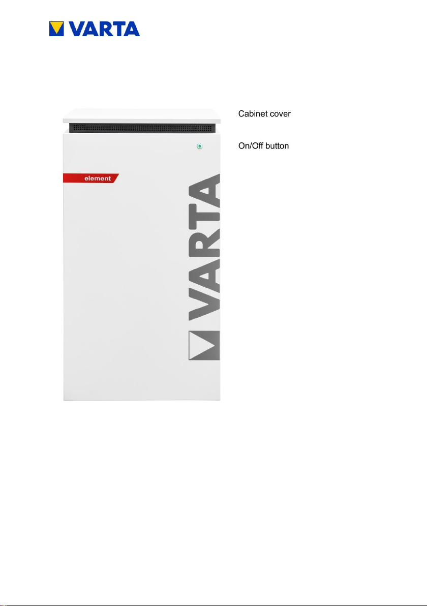
3.3 Front view VARTA element
Figure 1: Front view VARTA element
Subject to modification! Updated 10/2017
29
General
Operation
Installation
Operation (Service)
Maintenance
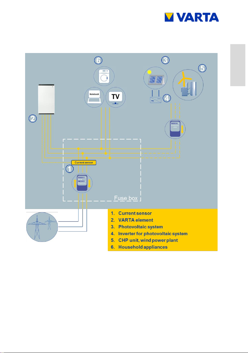
3.4 System overview
Figure 2: System overview VARTA element

30
Subject to modification! Updated 10/2017
Figure 3: Rating plate VARTA element
Figure 4: Cryptocode
3.5 Rating plate
 Loading...