

Page 1
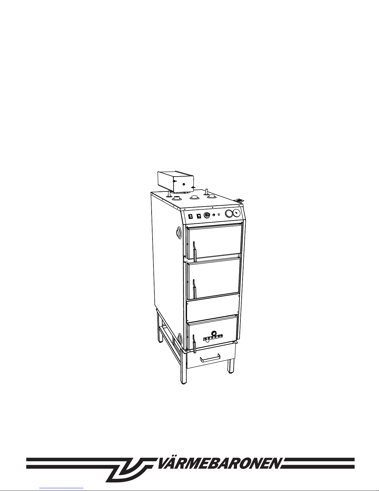
Installation, operation and maintenance
Firewood boiler
Vedolux 30
131216 V30 en_mcs rev1
Page 2
2
VÄRMEBARONEN VEDOLUX 30
Contents
Read this document carefully before carrying out any
installation, adjustment or service – and follow the
instructions.
The appliance is not to be used by children or persons with
reduced physical, sensory or mental capabilities, or lack
of experience and knowledge, unless they have been given
supervision or instruction.
Children being supervised not to play with the appliance.
Keep these instructions close to the boiler!
The boiler must not be modified, changed or rebuilt.
To guarantee high reliability, all installation, adjustment and
ongoing service must be carried out correctly.
The correct settings are important for economical heating.
The type and serial number of the boiler must be quoted
whenever you contact your retailer, see the rating plate.
For service issues, contact your installer.
Värmebaronen AB retains the right to change the
specification without prior notice, as part of its policy of
continuous improvement and development.
You may see the following symbols in these instructions
and on the product:
Information that is important for optimum func-
tion.
Tells you what you must – or must not – do in order
to avoid personal injury.
Tells you what you must – or must not – do in order
to prevent damage or disturbance to the component,
the burner, the process or the surroundings.
General
General ........................................................................................ 2
Notes ........................................................................................... 3
Function ...................................................................................... 4
Vedolux 30
Ceramic combustion chamber
Flue cleaning
Chimney
Accumulator tank
Delivery
Accessories
Technical data ............................................................................ 5
Installation.................................................................................. 6
Chimney
Flue pipe
Flue gas thermometer
Connection to accumulator system
Function of accumulator control
Ex pansion system
Vented
Unvented
Cooling coil - temperature limiter
Turbulators
Bracket for cleaning tool
Draught hatch
Pellet burner/oil burner
Electrical connection ................................................................. 8
Electrical connection
Wiring diagram and control panel ............................................ 8
Function
Checks ........................................................................................ 9
Firewood ..................................................................................... 9
Firewood as a fuel
Firewood
Heat content
First burning cycle
Firewood as a fuel ...................................................................... 10
First burning cycle
Lighting a fire without gas
Lighting a fire with the gas lighter
Adding wood
Bypass damper
Controlling combustion
Cleaning ...................................................................................... 11
Cleaning the boiler
Chimney sweeping
Cleaning the fan
Operation and care .................................................................... 12
Ceramic - combustion tunnel
Safety valves
Venting
Water pressure in the system
Unvented expansion system
Overheating protection
If there is a risk of freezing
Draining the boiler
Boiler cleaning
Pellet burner
Power failure
Problems burning firewood ....................................................... 13
Component specification .......................................................... 14
Page 3

3
VÄRMEBARONEN VEDOLUX 30
To be completed when the Vedolux 30 is installed!
Serial number: .........................................................................................................................................
Installation date: .........................................................................................................................................
Installer: .........................................................................................................................................
Tel: .........................................................................................................................................
Other: .........................................................................................................................................
.........................................................................................................................................
.........................................................................................................................................
.........................................................................................................................................
.........................................................................................................................................
.........................................................................................................................................
Notes
Page 4

4
VÄRMEBARONEN VEDOLUX 30
Function
Vedolux 30
• is a firewood boiler with a suction fan, designed for heating houses
and smaller properties.
• is environmentally-approved for firewood burning with an
accumulator tank.
• is designed for half metre firewood (20 in).
• is designed to be connected to an external water heater.
• is primarily designed to be fired by firewood, but can also be
modified for use with a pellet burner.
• has an output of 33 kW when burning firewood and 40 kW when
burning pellets.
Ceramic combustion chamber
The combustion chamber is designed for reverse combustion. The
depth of the combustion chamber is 21.7 in. A bypass damper
prevents smoke entering the room when firewood is added.
Flue cleaning
All flue ducts in the boiler are cleaned from the same hatch at the
front of the boiler. The hatch is hinged and is opened with a single
operation. The flue ducts are round, which means there are no
awkward corners when flue cleaning.
Chimney
The Vedolux 30 has a suction fan minimising the chimney
requirements of the boiler.
Accumulator tank
To optimise combustion and efficiency, and to meet environmental
requirements relating to firewood burning, the boiler must be
connected to an accumulator tank. The accumulator tank is
dimensioned according to the requirements of the building.
Delivery
The product is delivered with the following components:
• flue pipe.
• flue cleaning tool with bracket.
• flue gas thermometer.
• drain valve.
• gas lighter.
Accessories
• base frame to make firewood burning more convenient.
• Accumulator Control 3.
• hatch set for pellet burner
Page 5
5
VÄRMEBARONEN VEDOLUX 30
Technical data
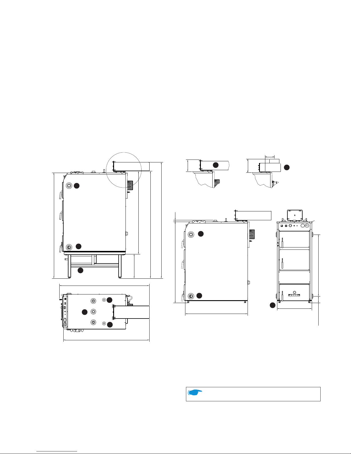
1. Hot water outlet, riser, R32.
2. Hot water outlet, return, R32.
3. Flue pipe, standard.
12 Base bolts, adjustable.
13. Connections for cooling coil, 15 mm Cu.
14. Expansion connection, R25.
18. Flue pipe up, accessory.
19. Base frame, accessory.
A
A
1488
+20
-0
343
+20
-0
1167
1510
+20
-0
1637
+20
-0
1265
1209
166
876
1145
+20
-0
21
489
868
95
+20
-0
145
210
2
3
12
13
14
1
1
2
13
18
19
Minimum distance of 200 mm between rear of boiler
and wall!
Pressure drop
45 mBar: 20°C 1,13 m³/h
58 mBar: 10°C 1,46 m³/h
Weight
empty
filled with water
290
390
kg
kg
Volume
100 litre
Design pressure
1.5 bar
Test pressure
2.15 bar
Pressure drop
water flow 0.54 l/s 10 mbar
Design temperature
110 °C
Operating temperature
< 93 °C
Output
wood, moisture 17 ±3 %
pellets
33 40kW
kW
Power consumtion
0.23 A / 50 W
Protection class
IPx1
Combustion chamber
volume
depth
90
550
litre
mm
Length of wood
500 mm
Burning cycle moisture content 17 ±3% 3-3.5 h
Firewood hatch
w x h 300 x 246 mm
Chimney requirement
height 3.5 m
flue duct recommended Ø 145 mm
165 cm
2
flue duct Ø 100 mm
79 mm
2
draught -10 / -20 Pa
Flue gas temperature
180 °C
Boiler class EN 303-5 Class 3
Page 6
6
VÄRMEBARONEN VEDOLUX 30
The installation must comply with the applicable
regulations and standards.
The boiler must be installed indoors in a cellar or on the
ground floor. The installation site
must be able to support the combined weight of the boiler, the accumulator tank and any chimney.
The boiler can support up to 150 kg
of the weight of the chimney.
Adjust the base bolts to make the
boiler level.
A discharge pipe connected to the
safety valve is to be installed in a
continuously downward and in a
frost-free enviroment.
A thermal discharge safety device
(STW) must always be installed on
the boiler, cold water approx. 10°C, min 2 Bar.
The boiler must be connected to an accumulator tank, and
the installation must include an accumulator control, min. return temp. 60°C
You must contact the chimney sweep before changing to a
different form of energy.
Contact the municipality to find out about restrictions on the
use of solid fuels in built-up areas.
The fresh air intake of the boiler room must have at least the
same cross sectional area as the chimney, and it must be designed so it is impossible to close it by mistake.
Chimney
The Vedolux 30 has a suction fan minimizing the chimney requirements.
Flue gas thermometer
Flue pipe
The boiler is supplied with an angled flue
pipe – a flue pipe running up from the
steel pipe is available as an accessory.
Fasten the flue pipe to the flange on
the boiler using the 4 x M8 screws
supplied, with washers. Remove
the cleaning hatch first. Two sets
of holes are provided to cover the
360° angle of rotation.
Flue gas thermometer
Install the supplied flue gas thermometer in the outlet of the flue
pipe, see the illustration above.
Connection to accumulator system
The boiler must always be connected to an accumulator tank with
an accumulator control.
The accumulator volume is dimensioned according to the surface
area to be heated. Allow for 8 – 10 litres of tank volume per square
metre of heated surface area.
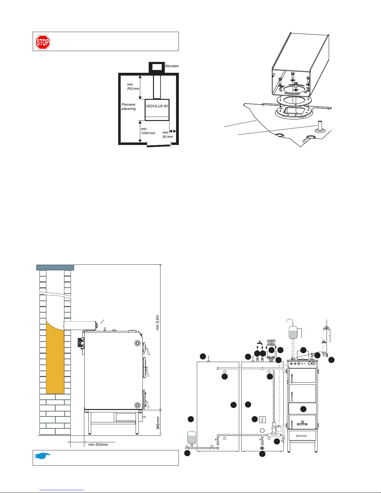
The schematic diagram below shows the Vedolux 30 with the
Aqualux and Aqualux UB accumulator tanks plus Accumulator
Control 3. For more details, refer to the documentation supplied
with the relevant product. Follow the installation instructions in the
documentation.
The pipe dimension between the boiler and the tank should be
28/35 mm for copper pipe or equivalent.
This diagram illustrates the system principle – the actual system
will be designed according to the applicable standards and the
instructions supplied with each component.
Installation
Minimum distance of 200 mm between rear of boiler
and wall!
STW
Cold water
(or vice versa)
UNVENTED
SYSTEM
VENTED
SYSTEM
HW
11
46
47a
47b
48
49
50
51
52
53
54 55
56 57
58
59
60
11
48
60
Page 7

7
VÄRMEBARONEN VEDOLUX 30
Installation
11: Draining valve
46: Expansion system, open or closed
47a: Aqualux 750 CU - 47b: Aqualux 750 UB
48: Automatic air release valve
49: Ackstyrning 3, Accumulator control
50: Vedolux 37 Wood log boiler
51: Flue pipe
52: 1.5bar safety valve
53: Shunt valve
54: Flow
55: Return
56: Cold water inlet
57: Hot domestic water outlet.
58: STW
59: Immersion heater
60: Thermometer
Function of accumulator control
The accumulator control ensures that the boiler reaches a high
working temperature before it starts charging the accumulator
tank. It also prevents the return temperature to the boiler falling
too low, min. 60°C, helping to minimise the risk of condensation in
the combustion chamber. The charging pump of the accumulator
system is controlled by a flue gas thermostat.
Expansion system
The boiler is connected to a vented or unvented expansion system.
The volume of the expansion vessel is dimensioned according to the
circumstances. The guideline values for volume are approx. 5 % of
the total system volume for vented systems, or 13- 15 % for unvented
systems.
Vented The distance between the top of the highest radiator
and the expansion vessel must be at least 2.5 metres
in order to prevent oxygen saturation of the water in the
heating system.
The expansion vessel is connected in a continuous and
unisolatable rise from the boiler's expansion connection.
To prevent damage occurring if the expansion system
fails, for example because of freezing, the boiler should
be fitted with a t ype approved safety valve, 1.5 bar.
Unvented In unvented systems, the boiler must be fitted with a
type approved safety valve, 1.5 bar, connected using an
unisolatable pipe from the connection at the top of the
boiler, as well as a bleed valve.
The expansion vessel is best connected using 15 mm Cu
pipe, as shown in the diagram on the previous page.
The opening pressure of the safety valve is based on the
lowest maximum pressure that any system component
can withstand.
Cooling coil - temperature limiter
The boiler are equipped with a cooling coil, this must be
supplemented with a STW. STW, thermal discharge safety device
is used for limiting the temperature by opening a valve (normally
by circa 97˚C) and letting cold water enter the cooling coil. This will
limiting the boiler temperature to under 110˚C. An STW of any brand
can be used. Follow the instructions of the manufacturer. (When
not having mains water, make sure there always are enough cooling
water when there is a power cut off).
Filling the heating system
The boiler must be fitted with valves for filling and draining.
Turbulators
The five turbulators are installed in the flue gas pipes as shown in
the diagram. The purpose of the turbulators is to introduce turbulence to the flue gases, causing more heat to be transferred to the
boiler water.
If the flue gas temperature falls too low (with a wide and long
chimney), there is a risk of condensation in the flue duct. To
increase the temperature, the three upper turbulators can be
removed, or cut to a length that produces a suitable flue gas temperature The draught hatch is another way of reducing condensation problems.
3 st
2 st
30
31
30
31
29
Bracket for cleaning tool
The bracket for the cleaning tool can be fitted to either side of the
boiler or any suitable place close to the boiler.
Draught hatch
An extremely high chimney and/or strong winds can create a
draught that is strong enough to allow combustion with the fan
turned off. The solution is to install a draught hatch, which can
reduce the draught to 10-15 Pa.
Pellet burner
The Vedolux 30 is primarily designed to be fired by firewood, but
can also be modified for pellets using a pellet burner.
When the pellet burner is used, the accessories supplied with the
pellet hatch set must be installed:
• Pellet burner should be installed in the fire wood hatch.
• Hatch, designed for the Viking Bio pellet burner.
• Cover plate with draught hatch, instead of the fan on the rear of
the boiler.
• Cover plates for the primary damper behind the plate on the front
of the boiler.
• Cover plate for the secondary damper.
Because of the risk of condensation you should monitor the flue
gas temperature. Check that the flue gas temperature is appropriate for the chimney type.
Otherwise, follow the instructions of the burner manufacturer.
Page 8
8
VÄRMEBARONEN VEDOLUX 30
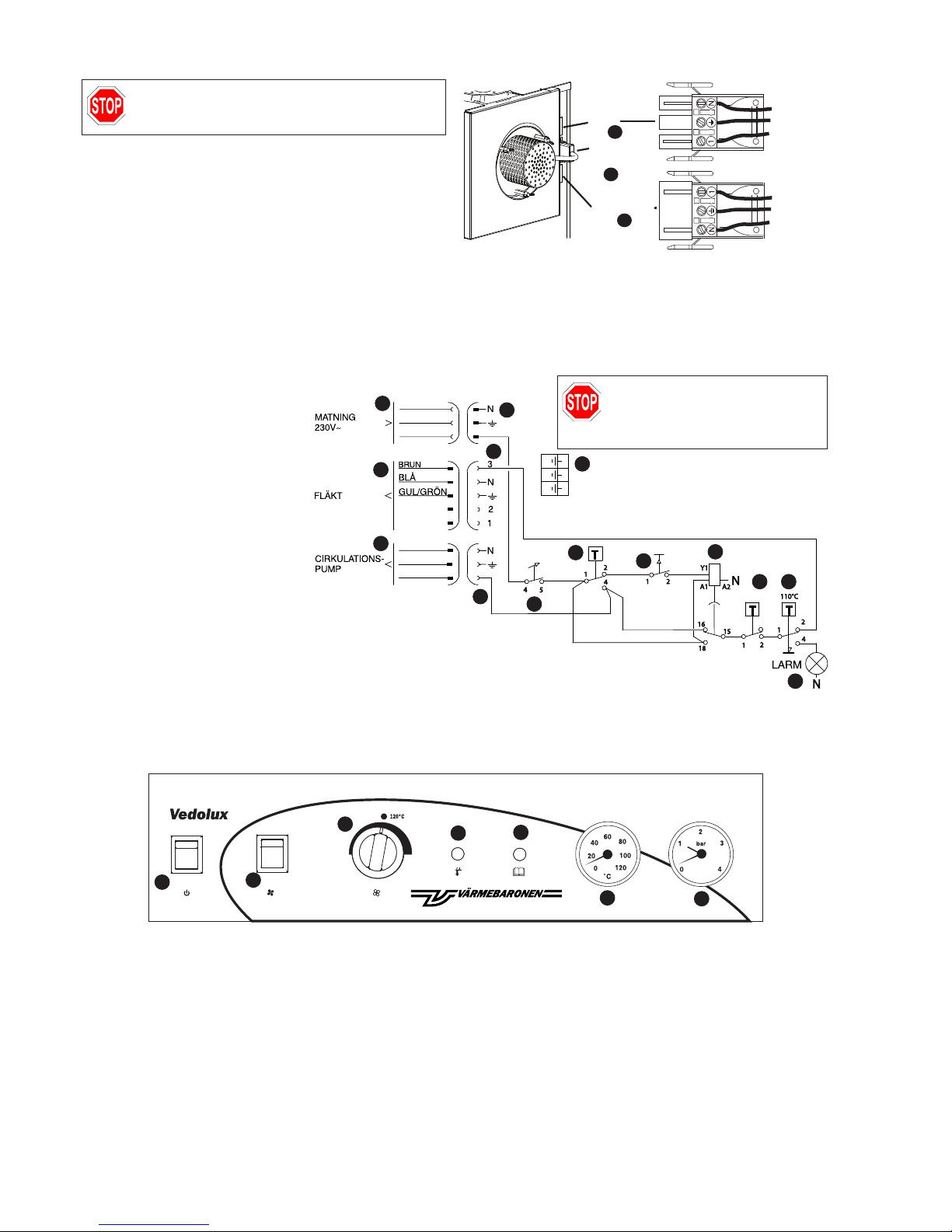
Electrical connection
20
22
21
25
26
27
28
Electrical installation must be in accordance with
the applicable regulations, under the supervision of
an authorised installer.
Electrical connection
The boiler is connected directly to the mains.
The electrical connections are at the rear of the boiler, in the form of
three quick connectors:
15. Mains connection, 230 V~, cable with quick connectors supplied.
16. Fan.
17. Circulation pump, for charging the accumulator system.
Supply
Fan
Circulation pump
YELLOW/GREEN
YELLOW/GREEN
BLUE
BLACK
BLACK
BLUE
15
16
17
Function
Start with the boiler cold.
Set the main switch, 20, to the ON-position – the green area must be
visible.
Set the thermostat, “FAN STOP”, 21, to 120°C. The thermostat
detects the flue gas temperature.
Press “FAN START”, 22, the time relay, 24, is activated and the fan
starts.
When the time set for the time relay, 30 minutes, is reached, the
contact changes, which means that the fan and the charging pump
for the accumulator system are controlled by the thermostat, 21.
When the firewood is burnt out and the flue gas temperature falls
below the value set for the thermostat, 21, the fan and charging pump
stop running.
If the boiler temperature exceeds 105°C, the overheating protection is
triggered. The fan stops running and the charging pump continues to
operate. If the overheating protection, 25, is triggered, the “ALARM”
indicator, 26, is lit.
An thermostat limits the boiler’s working temperature.
93°C
15. Supply connection, 3-pole connector.
a. cable part, socket.
b. chassis part, plug.
16. Fan connection,
5-pole connector.
a. cable part, plug.
b. chassis part, socket.
17. Connection for charging pump, 3-pole
connector.
a. cable part, plug.
b. chassis part, socket.
18. Terminal block for internal earth connections.
20. Main switch.
21. Thermostat for fan and charging pump.
22. Fan start, cold boiler.
23. Limit thermostat.
24. Time relay, delayed cutoff.
25. Overheating protection.
26. Indicator showing triggered overheating
protection.
25
15a
16a
17a
18
20
21
22
23
24
26
15b
17b
16b
27. Thermometer, displays the boiler temperature.
28. Pressure gauge showing the water
pressure in the heating system.
Always disconnect the power supply
to the boiler before accessing the
automation cabinet or units powered
by the boiler.
Wiring diagram and control panel
Page 9

9
VÄRMEBARONEN VEDOLUX 30
Checks
Firewood as a fuel
Vedolux 30 has a ceramic grate and an afterburning chamber made
of high-temperature resistant stainless steel. The boiler works on
the principle of reverse combustion. If the boiler is correctly operated, it burns firewood and gases very effectively, with high efficiency
and low environmental impact.
Using firewood as a fuel is not simply about burning the wood – the
techniques used have a decisive effect on the result.
Firewood
Hardwoods generally have a higher energy content than conifers.
However, the most important thing is that the wood must be dry –
moisture content 12-25 %.
If the wood is damp, much of the energy is wasted on drying it out,
combustion is impaired and the risk of tarring increases.
Oak should be well dried, for more than three years, and or mixed
with other wood types to avoid the negative factors of high acidity.
The blocks of wood must be the correct size for the combustion
chamber, around 50 cm long and around 15 cm wide, allowing
three blocks to fit the width of the grate.
To allow the wood to dry out, the tree should be felled at least one
season in advance. An alternative method is to fell the tree in spring
just after the leaves have come out, then wait a few weeks before
trimming and splitting the wood. During these weeks, the leaves
wilt and draw out the moisture. After another few weeks of drying,
the wood has 25-30 % moisture content.
After cutting, the wood must be split. The more it is split, the faster
and easier it will dry. If logs are difficult to split, the bark can be
stripped to speed up drying. Fresh wood is easiest to split.
The wood should not be in direct contact with the ground, as this
causes the wood to take on moisture instead of drying out. Ideally
the wood should be kept under a roof but in a place where the sun
and wind can help dry it. The best place for final drying is the boiler
room, for 2-3 weeks before the wood is used. The moisture content
after drying is around 20 %.
Firewood
Heat content
The heat content is the amount of heat that can be extracted by the
boiler and transferred to the boiler water. Heat content should not
be confused with energy content, which increases with the size of
the block of wood. The heat content increases with the dryness of
the block of wood, because less heat is wasted on drying the wood.
Newly cut wood has a moisture content of around 55 %. Firewood
that has been dried out following our instructions has around 20 %
moisture.
First burning cycle
In the first burning cycle, or if the boiler has not been used for a
while, it is important to just light a small fire. The ceramic parts of
the boiler may contain moisture, which must be vaporised slowly
so as not to crack the ceramic. Once the ceramic parts are dry,
you can light a full-size fire. The ceramic does not take on moisture
when the boiler is being used. See “Operation and care”.
After installation, check with
the installer that the system is
in perfect condition.
Ask the installer to demonstrate
the settings and functions so
you know how to operate and
care for the system.
Loosen the plate, dampers
at the rear.
Checks
Before putting the system into operation, check that:
• the system is filled with water
• all connections are watertight
• flue gas connections to the boiler and to the chimney are tight
• the filling/drain valve has been closed properly.
• the primary damper is in position (may become detached during
transport)
• the safety valves are working correctly
• the necessary valves are open
• the circulation pump is working and the direction of flow is correct
• the correct temperature has been set on the charge thermostat
Page 10
10
VÄRMEBARONEN VEDOLUX 30
20
22
21
25
26
27
28
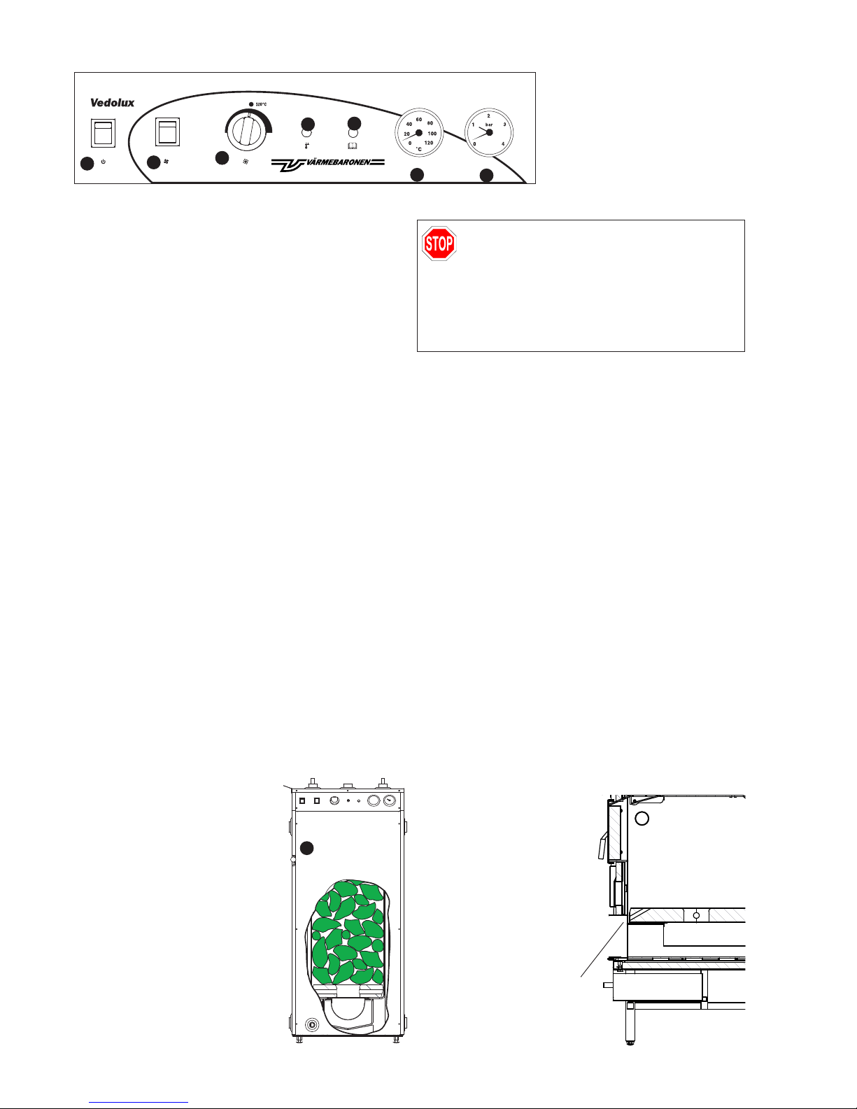
20. Main switch.
21. Thermostat for fan and charging pump.
22. Fan start when the boiler is cold.
25. Overheating protection.
26. Indicator showing triggered overheating protection.
27. Thermometer, displays the boiler
temperature.
28. Pressure gauge showing the water
pressure in the heating system.
Firewood as a fuel
8
Opening for
gas lighter
First burning cycle
First check that the combustion tunnel is firmly seated and that the
air control pipe, 34a, has not moved during transport.
The first fire to be lit should be started carefully so that any remaining moisture in the ceramic can vaporise slowly. Lighting a fierce fire
may crack the ceramic Only light a small fire the first time. Once the
ceramic parts are dry, you can light a full-size fire. The ceramic does
not take on moisture when the boiler is being used.
Lighting a fire without gas
• Move the main switch to the green position. Set the thermostat to
120°C.
• Arrange kindling on top of crumpled newspaper. Push some of the
paper down into the hole in the ceramic. Close the firewood hatch.
• Press “FAN START”, the fan starts. Open the bypass damper. Open
the ash hatch and light the paper.
• The wood must be properly ignited (flue gas temperature approx.
120°C). Leave it to burn until there is a layer of vigorous embers.
Open the ash hatch and the bypass damper.
Lighting a fire with the gas lighter
• Move the main switch to the green position. Set the thermostat to
120°C.
• Arrange medium size blocks of wood over a layer of kindling, then
fill the rest of the combustion chamber with firewood.
• Press “FAN START”, the fan starts.
• Open the bypass damper and ash hatch. You can leave the firewood hatch open until you can see the flames.
• Ignite the gas lighter and insert it into the nozzle in the opening
(see the diagram below). After around 1-2 minutes the firewood
should be lit.
• Remove the gas lighter, close the ash hatch, close the firewood
hatch, close the bypass damper. Check that you can see flames in
the inspection glass.
Adding wood
To prevent smoke and flames entering the
room when adding wood, you must open
the bypass damper before opening the
firewood hatch.
Only add more firewood when all that is left
of the previous load is a layer of embers.
Constantly “topping up” with the occasional
log reduces efficiency significantly.
Even out the layer of embers. Add more
firewood. The amount of firewood depends
on the temperature in the accumulator – do
not allow the temperature to get too high.
Filling the boiler with firewood increases the temperature of the
boiler and a 1500 litres gal. accumulator by 40- 50°C. Stack the
wood carefully, the boiler can be completely filled.
Close the firewood hatch and then the bypass damper. If the flue gas
temperature increases, you know that the firewood has ignited.
When the firewood has burnt and the flue gas temperature has fallen
to below 120°C, the fan and charging pump to the accumulator stop
running.
Bypass damper
The boiler’s bypass damper must only be used for adding wood during a burning cycle, in order to prevent smoke entering the room.
When the bypass damper is open, the boiler works like an updraught
burner with shorter flue gas paths. This increases the flue gas temperature and reduces efficiency.
Do not forget to close the damper after adding firewood.
Controlling combustion
Air is supplied to the boiler partly through the primary damper, which
is hidden behind the cover plate on the front, and partly through the
secondary damper in the lower ash hatch. Combustion is controlled by the draught created by the fan, and by the addition of oxygen
through these dampers. To optimise combustion and efficiency, the
flue gas temperature should be 175- 210°C.
The secondary damper can be
adjusted so that the flame is light
yellow.
The soot indicates the quality of
combustion. If it is very dark or
black, the combustion process is not
receiving enough air. In this case,
the damper should be opened more.
Efficient combustion gives the soot a
grey-brown colour.
RISK OF BURNS
Do not open the boiler hatches if the fan is not running and a fire is burning in the boiler. If you are not
sure whether a fire is burning in the boiler, first open
the bypass damper then open the firewood hatch a
couple of centimetres very carefully.
There is a risk of flames exiting through the hatch,
so take the greatest possible care!
Page 11

11
VÄRMEBARONEN VEDOLUX 30
Cleaning
3. Flue pipe, standard.
4. Fan motor.
a. long nuts, x 3.
7. Cleaning hatch.
8. Control for bypass damper.
9. Firewood hatch.
10. Ash hatch.
19. Base frame with ash pan (accessory).
29. Tool for removing turbulators.
30. Short turbulators, x 3, in upper pipes.
31. Long turbulators, x 2, in lower pipes.
34. Ceramic grate, x 2, front and rear with
a. air control pipe.
b. glass fibre packing between ceramic and
combustion chamber walls
35. Combustion tunnel.
43. Protective grating for fan.
44. Collection chamber.
When cleaning, the boiler must be completely cool
and all embers must have died.
Disconnect the power supply to the boiler before
cleaning.
Ashes may contain embers for a long time after the
burning cycle, so keep them in a non-flammable
container with a cover.
29
30
31
3
7
10
8
30
31
34
44
9
4
34a
34a
34b
4a
19
35
43
Cleaning the boiler
Rake the ashes from the combustion tunnel before each burning
cycle, but always leave a couple of centimetres as a protective layer.
It is normal for tar to form on the walls of the combustion chamber.
The tar does not need to be removed because it will burn off once
the layer has reached a certain thickness. The tar does not affect
the efficiency of the boiler, and the output of the boiler is calculated
and dimensioned on the basis of the heat conversion surface area
in the flue ducts. The flue ducts must be kept clean at all times. In a
cleaned boiler, less of the heat escapes with the flue gases. One way
of telling whether it is time for cleaning is to check the flue gas thermostat. It is a good idea to clean the boiler if the flue gas temperature is approx. 25°C higher than the temperature in a clean boiler.
• Open the cleaning hatch, 7.
• Pull out the three upper, 30, and the two lower, 31, turbulators,
using tool 29.
Clean the pipes with the pipe cleaner/brush. When cleaning the
three upper pipes, be careful not to push the pipe cleaner through
the grating, damaging the fan. You must not push the pipe cleaner
further than the end of the pipe - you can feel the difference in the
amount of force needed to push the cleaner.
Replace the turbulators.
• Open the firewood hatch, 9, and the bypass damper, 8.
Remove the ash on the plate in the upper front edge of the combustion chamber, 32.
There should always be a small quantity of ash on the ceramic
grate, 34, in order to extend the service life of the grate.
• Open the ash hatch, 10. Rake out the ash from the combustion
tunnel, 35, but leaving a protective layer of a couple of centimetres.
Clean the chamber around the combustion tunnel.
Close all hatches and dampers.
Chimney sweeping
After the chimney has been swept, unscrew the wingnuts on the
front of the flue pipe, 3 and 18, and remove the cover. Remove soot
and ash. Before restarting the boiler, remove any soot and ash that
has fallen onto the fan and into the collection chamber 44.
Cleaning the fan
If necessary the fan can be removed and cleaned, You should handle
the fan with care.
• Remove the fan connector, 16, from the boiler plug.
• Unscrew the long nuts, 4a, securing the fan.
• Clean the fan blades carefully so they keep their shape. You are
recommended to use a paintbrush.
• Replace the fan and connect the cables.
Page 12

12
VÄRMEBARONEN VEDOLUX 30
Operation and care
RISK OF BURNS
Do not open the boiler hatches if the fan is not running and a fire is burning in the boiler. If you are not
sure whether a fire is burning in the boiler, first open
the bypass damper then open the firewood hatch a
couple of centimetres very carefully.
There is a risk of flames exiting through the hatch,
so take the greatest possible care!
Ceramic - combustion tunnel
The ceramic grate and combustion tunnel are wearing parts that
will have to be replaced over time. Wearing parts are not covered
by any guarantee. Small cracks in the ceramic are not abnormal
and no action is necessary.
To increase the service life of these parts, follow these instructions:
• Do not remove the ceramic when cleaning the boiler combustion
chamber.
• Scrape the ceramic gently and carefully when removing ash from
the boiler.
• Leave a couple of centimetres of ash as a protective layer on the
grate and the combustion tunnel.
Pieces of charcoal from the previous burning cycle can be left for
the next cycle.
• Only use “real” wood, avoiding plastic, treated timber, refuse,
etc.
• Place the wood in the boiler, do not throw it in.
• If the boiler/ceramic is new or if the boiler has not been used for
a while, light a small fire to heat the ceramic and remove any
moisture.
Safety valves
In order to preserve the safety function, the safety valves for the
domestic hot water system and the heating system must be operated regularly, around four times a year.
Open and close the safety valve manually around four times a year,
checking that a small amount of water escapes and that the valve
closes again properly. The pressure-relief device is to be operated
regularly to remove deposits and to verify that it is not blocked.
Also check that there is sufficient pressure in the system. If necessary, add more water.
Venting
Regularly check that there is sufficient water in the heating system.
Air may remain in the system for a while after installation, so
bleeding should be repeated a few times. After bleeding, check the
pressure and add water if necessary.
Water pressure in the system
The pressure required in the heating system depends on the height
difference between the lowest and highest points in the system, the
static head. If the difference is 5 metres, the pressure is 0.5 bar, if it
is 10 metres, the pressure is 1 bar.
The necessary pressure in the heating system depends on the
height difference between the highest and lowest points in the
system, the static head.
The pressure in a heating system varies with the
temperature, so only add water if it is necessary.
The volume of water changes with the temperature, and the
change in volume affects the pressure in the system. The higher
the temperature the greater the volume and the higher the pressure. The expansion vessel takes up the changes in volume. The
flow temperature – and therefore also the pressure – is higher in
the summer than the winter.
Unvented expansion system
The pressure in the unvented expansion vessel should be checked
at intervals of several years. The vessel must not be exposed to
any pressure from the heating system.
Overheating protection
The overheating protection, which stops the fan if the boiler
temperature is too high, is reset on the boiler control panel. It is not
possible to reset until the boiler temperature has dropped below
95°C.
If there is a risk of freezing
In severe cold weather, no part of the heating system should be
turned off as this would involve a risk of burst pipes.
Never start a burning cycle if you suspect that any part of the heating system might be frozen. Call the installer.
If the heating system will be turned off for an extended period, the
water should be drained.
Draining the boiler
The boiler must not be running while it is being drained.
Close the valves to the heating system.
Run the water to a floor drain via a hose connected to the boiler
drain valve.
Allow air into the system by opening the boiler safety valve.
The drain valve for the heating system must be located in a con-
venient place.
Boiler cleaning
Keep the boiler clean and tidy.
Alkaline cleaning agents are useful for removing soot marks from
the boiler. Do not use strong solvents.
Pellet burner
For optimum reliability and efficiency, it is essential to check and
adjust the burner regularly.
Power failure
If there is a power failure, the fan will stop and the output of the
boiler will fall. In around 20 minutes, the output drops from 100%
to approximately 10%. If Värmebaronen’s instructions were followed when the accumulator tanks were connected, this output
can circulate naturally to the accumulator tanks.
Page 13
13
VÄRMEBARONEN VEDOLUX 30
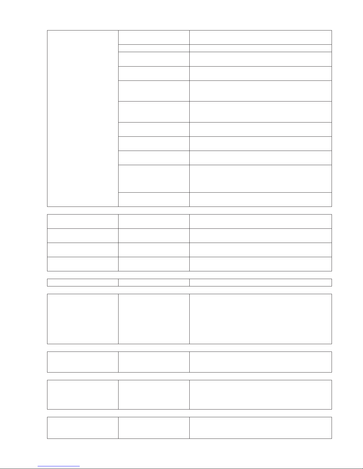
Problems burning firewood
Poor combustion.
Damp wood. A ceramic boiler requires a high combustion temperature. To achieve
this, the wood must be dry, moisture content 12- 25%.
Incorrect handling. Read the instructions.
The wood is not suitable for the
boiler.
The firewood should be approx. 20 in. long, with a width allowing three
blocks to fit the width of the grate.
Constant “topping up” Constant “topping up” lowers the combustion temperature and re-
duces the boiler output.
Shaped wood, rectangular wood. If uniform blocks of wood are stacked on each other, a sold mass of
wood is created with limited surface area for the fire to act on. Arrange
the wood so there are gaps between the blocks.
Fails to burn. The wood is bent and/or not suitable for the boiler. This is not the same
thing as the firewood burning to a different extent in different parts of the
boiler, which is normal.
Not enough air. Check that the air valve is open. The fresh air intake of the boiler room
must have at least the same cross sectional area as the flue duct.
Damper too open. If the damper is too open, the air will not be correctly distributed in the
boiler. Start with the damper fully closed.
The chimney runs downwards from
the boiler connection.
The turbulence created takes away some of the draught. Fill the lower
part with sand or similar material.
No accumulator control. A ceramic boiler is at its most efficient when the ceramic is hot. The
temperature in the boiler therefore needs to be increased quickly before
charging begins. The service life of the boiler is shortened if there is no
control system. Add a control system.
Ceramic not correctly positioned. If the boiler is new, check that the ceramic has not moved during
transport. Also check the seal with the combustion chamber walls.
High flue gas temperature.
Tar and soot in the pipes. Incorrect combustion. Check the firewood, the draught, the air intake
and the handling. Clean the boiler.
Bypass damper open. Close the damper. The bypass damper must only be opened for adding
wood.
Combustion tunnel in wrong
position.
The combustion tunnel must be inserted fully.
Faulty flue gas thermometer. The thermometer may have been damaged by cleaning or by long
periods of up draught burning.
Tar and soot in the pipes.
Incorrect combustion. See the section about high flue gas temperature.
Heat is not transferred from the
boiler to the accumulator.
Wrong connections. Check.
Circulation pump in accumulation
control.
Check that the pump is operational. Most pumps have a speed control –
check that the speed is not too low.
Air. Vent. Check the installation. If installation is carried out according to
“Connection to accumulator system”, the system will not be sensitive to
air problems.
Wrong connection of accumulator. See the points above.
Boiling noises.
Low pressure head. Check the pressure, which should be about 14.5 psi. The expansion
vessel must be dimensioned for the volume and for the temperature
variations that occur.
Fan fails to start.
Main switch in position O. Set the main switches to position I.
Forgotten to connect the instant
connector.
Connect the instant connector.
Overheating protection triggered. Reset the overheating protection.
The safety valve opens when the
system is warm.
Expansion vessel too small. See the section about the “Expansion system” on page 5.
Initial pressure in the expansion
vessel too high/low.
Check the pressure in the vessel, see the section about the “Expansion
system”.
Page 14

14
VÄRMEBARONEN VEDOLUX 30
Component specification
item prod.no. name qty.
25 12 00 17 Overheating protection 1-pole, alt. 110°C 1
21 12 00 53 Thermostat 1-pole 100-500°C 1
12 00 09 Handle thermostat 1
22 13 00 31 Switch 2-pole, auto-return 1
20 13 00 32 Switch 2-pole 1
18 16 00 01 Terminal block 3-pole 1
16 00 06 End plate 1
23 17 00 06 Relay 1-pole alt. 1
24 17 00 22 Time relay. 1
26 19 00 06 LED 230 V, red, pin 1
23 00 75 Damper arm 1
23 00 76 Damper arm lock 1
31 23 22 52 Turbulator 1000 mm 2
30 23 22 53 Turbulator 436 mm 3
5 29 50 05 Cleaning tool bracket 1
30 00 11 Glass fibre cord 10mm (m) 1.7
30 00 30 Ceramic fibre paper 1x25mm (m) 1,1
34 31 04 02 Grate front, V-30 1
34 31 04 03 Grate rear, V-30 1
9 71 05 06 Firewood hatch 1
10 71 04 94 Draught hatch, V-30 1
37 00 60 Handle knob 25 mm 2
28 38 00 01 Manometer 0-4 bar 1
27 38 00 03 Thermometer. 0-120°C 1
38 00 30 Flue gas thermometer 50-500°C 1
44 00 02 Pipe cleaner 89 mm 2
44 00 05 Pipe cleaner 595x80x60/30mm 1
44 00 11 Spring steel shaft 1500 mm 2
15b 44 01 53 Inlet 3-pole female 1
44 01 54 Panel fixing 3-pole 2
17a 44 01 59 Plug 3-pole 1
16b 44 01 66 Outlet 5-pole for panel 1
16a 44 01 67 Plug-on contact 5-pole 1
17b 44 01 68 Inlet 3-pole male 1
15a 44 01 69 Plug 3-pole 1
44 02 27 PowerJet gas lighter 1
4 50 00 09 Fan V-37F 1
70 02 05 Insulation for cover of flue gas fan 1
70 00 86 Fan gasket 1
35 71 04 53 Combustion tunnel 1
71 06 69 Bypass damper 1
71 05 21 Damper arm 1
29 71 02 60 Turbulator tool 1
71 05 62 Ash rake 1
7 71 04 82 Cleaning hatch 1
45 120006 Termostat EGO 1-POL, 30-93° 1
Page 15

Page 16

Varmebaronen UK
11 Back O'Hill,
Stirling. FK8 1SH
T
01786 849 099
F 01786 849 098
ww
w.varmebaronen.org
 Loading...