

Page 1
Please read the instruction manual thoroughly before
operating your GT stabilizer for the first time to avoid
injuring yourself or damaging the unit.
The robust construction of the GT makes it an excellent
long-term investment, but its precision design also means
that you must exercise care in the storage, transport, and
operation of the unit to ensure optimal long-term
performance.
You should also review the accompanying instructional DVD
before attempting to shoot usable footage with the GT. The
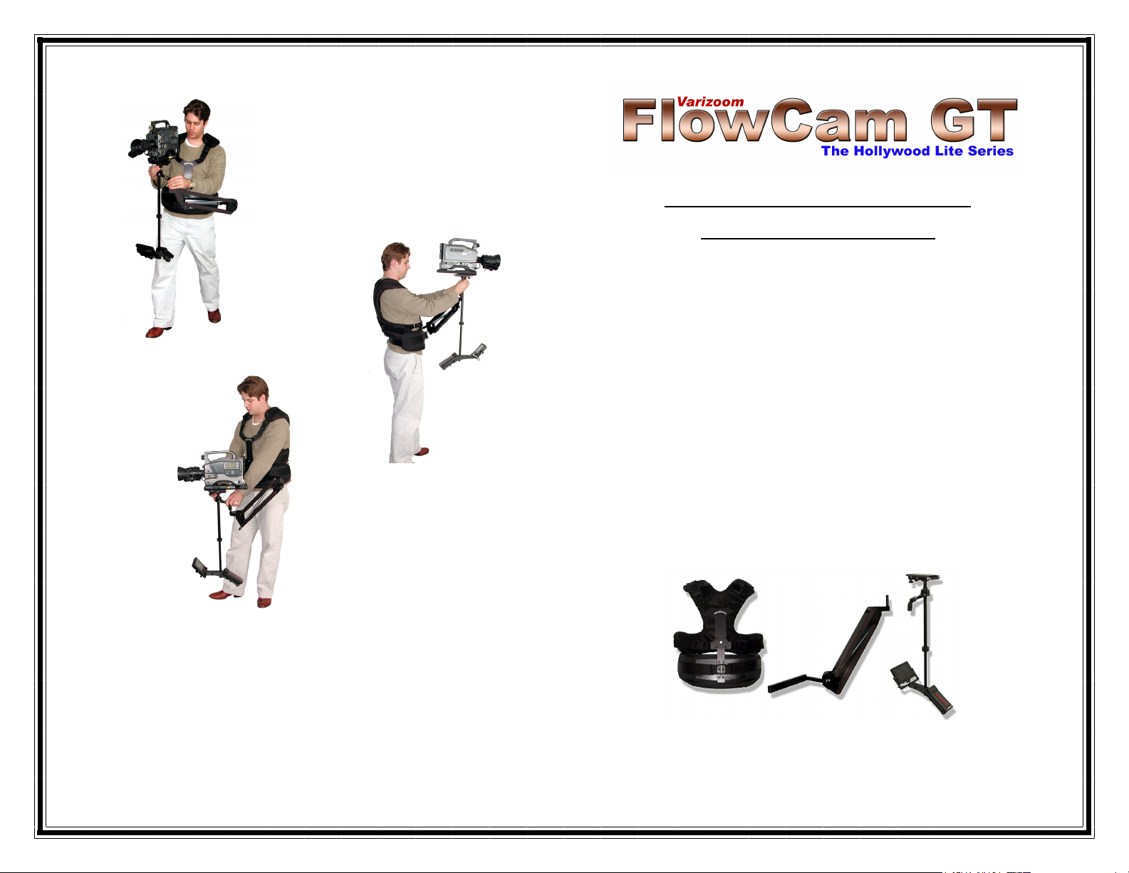
standard GT comes equipped with three subsystems:
VEST ARM SLED w/ monitor
and the following: padded case, DVD, hex wrench, BNC-
RCA video cable, battery/charger, & docking post (for
mounting sled on a C-stand or light stand).
VZ-GT Camera Stabilizer
Instruction Manual
Page 2
Page 2
For GTs Equipped with Optional Battery Mounts
If you ordered your GT with one of the optional battery
mounts (Anton Bauer, NP1, V-lock), your kit will not include
the battery and charger. You must supply your own battery
system in this case.
Subsystems
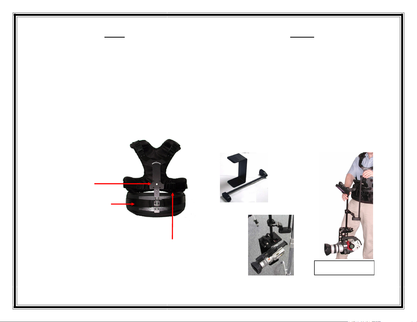
The Vest
The purpose of the vest is to comfortably distribute the
weight of the camera and stabilizing system on your body.
To achieve optimal results, you should adjust the vest so
that it fits snugly.
Adjust the vertical fit by
adjusting the straps, pulling
the chrome release pin and
sliding the chest plate up or
down until you find the right
position.
Adjust the tightness of the
vest around your waist/hips
using the Velcro strap,
drawing it around evenly on
both sides of the lower vest
pad.
Adjust the tightness around your torso by positioning the
Velcro straps across the back of the vest and securing the
buckles to the chest plate. Make the vest as tight as
possible to maximize operational quality and comfort. Once
you’ve adjusted the vest, remove it for easy re-suiting by
unclipping the buckles & strap on one side only.
Page 11
Low Mode Assembly
The Low Mode kit consists of the camera cage, the sled-toarm tie rod, and a few screws. Start by attaching the
dovetail plate, upside-down, to the top of the camera cage
using the supplied screws (the top of the cage has threaded
holes). Then turn the GT sled upside-down and slide the
dovetail plate into the stage. Mount the camera inside the
cage using the supplied screw. Connect the sled to the arm
using the tie rod; the gimbal handle should fit into the round
hole on the oval shaped end of the tie rod and the squared
end should slide over the post on the spring arm. The stage
knobs and multiple cage holes allow for horizontal balance
adjustment, and you can adjust the vertical balance using
the same adjustments as in normal upright mode.
Camera cage may differ
slightly from those pictured
Page 3

Page 4
First, insert the battery into its housing, making sure the
electrical contacts are firm, and tighten the screws. To
prepare the camera for attachment to the sled you should
first find the center of gravity (CG) of the camera. The CG
is the point at which the camera will balance best, and it can
be determined by using a rounded object such as a pencil.
Set the camera lengthwise on top of the pencil so that it is
balanced to find the lateral center (side-to-side), and then
set it on top of the pencil in a perpendicular orientation to
find the longitudinal center (front-to-back). The spot where
the lateral and longitudinal centers intersect is the CG – you
may want to mark it with a grease pencil or marker
(depending on how pristine you want to keep your camera).
Once the CG is determined, you must mount the camera to
the dovetail (mounting plate) using a hole that will put the
CG closest to the center of the mounting platform. Look at
the bottom of the dovetail, and on one side you will see a
row of metal teeth (the ‘rack’) and on the other side a pair of
sloped end stops. When you attach the dovetail to the
camera, you want the rack to be on the same side as the
LCD panel/viewfinder so that it will line up with the brass
pinion gear in the dovetail channel of the stage.
Locking
Pin
Lateral adjustment
Dovetail lock
Longitudinal adjustment
Page 9
You can also fine-tune the horizontal and vertical balance
by adjusting the position of the battery housing. On the
underside of the base of the sled, directly beneath the
battery housing, you will find a thumbscrew. When
loosened, the battery housing will slide down and back.
This will affect both the vertical and horizontal balance.
Special Note: Cameras near the top of the GT’s weight capacity may
need additional counterweight to achieve proper vertical balance. If you
cannot achieve vertical balance by adjusting the gimbal position upward
and extending the lower sled and battery housing fully, you may need
the lower sled side weights. If these were not included with your new
unit, they are available at no charge (see below).
The next step is to set the “float point”. This is essentially
the ideal point of arm spring tension, the state in which the
sled rises and falls with slight force. At the end of the arm
you will find a thumbscrew for adjusting the spring tension.
Clockwise turning increases tension while counter-clockwise
turning decreases tension. You should adjust the tension
until the camera base floats at a level below your
collarbone, but the arm should not feel “mushy”.
The float point is not necessarily an exact setting, and you
may find that what works for you may be slightly different
than another person’s preferred float point. The important
thing is the end result: you have a sled that rises and falls
with slight force and absorbs most of the shock imparted by
walking.
Page 4

Page 10
Now you should be able to turn on the monitor and begin
practicing, assuming the battery is charged. You may need
to adjust the balance slightly after positioning the monitor.
OPERATION
For instructions on operation, watch the DVD. Generally
speaking, you have to keep in mind that the stabilizer will
not work like a magic wand and instantly transform your
shots into brilliant footage. Operator skill is critical, and it
takes many hours of practice to master this device, but the
reward for all the practice will be substantial. Here are a
few simple quick-start guidelines:
-Hold the system by the gimbal handle to control the
orientation and elevation of the sled.
-With the other hand, lightly grasp the center post of
the sled just below the gimbal, holding it close to the
gimbal for optimal control.
-Delicately grasp the center post with your fingertips,
like a flute – do not grab it like a handlebar.
-Practice good posture and hold the sled close to
your body.
-Fine-tuning of the balance adjustments may be
necessary a few times during operation.
-The way you walk will affect the quality of
stabilization, so you will need to develop a lightfooted rhythmic pattern.
-Practice for at least 20 hours before attempting to
acquire usable footage.
The DVD contains detailed, clear instructions and tips on
operation, and if you have any general questions, visit the
website – www.varizoom.com. If you’ve watched the video
and practiced and still have technical questions, call 310545-0466.
Page 3
The Sled
The Sled is the subsystem that holds the camera, viewing
monitor, and battery. The Sled mounts to the arm, and in
tandem they create a stabilizing effect.
The Sled can be adjusted at
various points to change its
weight distribution, which in turn
enables you to accommodate
cameras of different sizes,
shapes and weights. The basic
principles of sled adjustment
are that you want the section of
the sled below the pivot point to
be effectively heavier (slightly)
than the upper section, and you
want the camera’s mass to be
centered on the rotating axis.
The Sled consists of three main sections:
The Stage enables you to adjust the
horizontal balance of the system and also
houses the video and power connectors.
The Post and Gimbal provide smooth
pan and tilt action, a mounting socket for
the spring arm, and a grip handle. This
section also features one of several
vertical balance adjustment points.
The Lower Sled holds the LCD monitor
and the battery power source. This
section provides a few vertical and
horizontal balance adjustment points.
Page 5

Page 6
If your fully loaded camera weighs less than 6 pounds, you
will have to remove the non-adjustable spring. If it weighs
more than 11 pounds, you will have to replace the nonadjustable spring with a heavier one.
A1 – Start by opening the arm (see below) Once you’ve
removed the two screws, you will be able to swing the top
half of the arm out and have access to the inside of the arm.
Remove two hex screws, one from each side at the top of the arm, as
pictured (5/64” key, not included)
Next, remove ONLY the spring attached to the stationary
bar – NEVER remove the spring on the adjuster assembly.
Remove the spring from the stationary bar by grabbing it
along its length and pulling it up and over the bar.
A2 - If your fully loaded camera weighs more than 11
pounds, you will need to replace the non-adjustable spring
with the supplied heavier spring. If it is less than 6 pounds,
removing the non-adjustable spring is all you have to do.
Page 7
Fold the arm back together and replace the screws. Recap:
2-6 lbs. = adjuster spring only
6-11 lbs. = adjuster spring + light spring on stationary bar
11-16 lbs. = adjuster spring + heavy spring on stationary bar
*****
You are now ready to put the systems together and learn
the balancing and operation procedures. Re-suit yourself
with the vest and remove the aircraft pin from the arm
socket on the lower center section of the vest. Install the
arm and replace the aircraft pin completely. Make sure the
battery is installed securely on the lower sled. Note: You
can also balance the sled while mounted on a C-stand.
Place the gimbal handle of the sled (with camera mounted)
onto the steel post at the top of the arm (the post should be
reversed for storage/transport). The post should slide up
into the socket of the gimbal handle. Now you can check
the vertical balance of the sled. Grasping the gimbal handle
as a control point, hold the arm close to your body. Using
your free hand, turn the sled 90 degrees so that it is
horizontally oriented, and let it drop back to the vertical
position. Keep your free hand close to the center post in
order to prevent the sled and monitor from colliding with
other objects.
Page 6

Page 8
Ideal vertical balance is reflected by a “drop time” of 2-3
seconds, meaning it should take 2-3 seconds for the sled to
swing down 90 degrees to the vertical plane (it will swing
past that point, but count only until it reaches the vertical
plane). If the system is top heavy, adjust the balance by
repositioning the gimbal clamp upward (with supplied 3/16”
hex key), and if it is bottom heavy, move it downward.
When you loosen the gimbal clamp, you should support the
weight of the sled by grasping the center post firmly. You
will notice that the gimbal clamp can slide up or down when
loosened – leave a gap between the gimbal clamp and
the bearing below it. If the gimbal clamp rides on top of
the bearing, it will cause drag on the panning action.
You can also adjust the vertical balance by extending the
lower sled downward. Positioning the lower sled downward
will make the system more bottom heavy, and it provides
you with the capability of shifting the balance down without
moving the gimbal to a position lower than you find
agreeable. To extend the lower sled, loosen the hex screw
on the knurled clamp (using the 3/16” hex key) while
supporting it from below. Be careful not to overextend the
lower sled, as there are wires inside the center post (there is
a safety catch, but don’t test it). When you find the right
position, tighten the knurled clamp again, but don’t tighten it
excessively – just tighten enough to fix the lower sled in
place. Adjust until you get a 2-3 second drop time.
Now you can proceed with the horizontal balancing, which is
accomplished by adjusting the longitudinal and lateral
positions of the camera. First you will have to loosen the
dovetail lock. If the sled tilts forward or backward, you can
adjust the position of the dovetail using the knob at the front
of the stage. If the sled tilts to one side, you can adjust the
Page 5
stage laterally by using the second knob. Both adjustments
allow for very fine increments, so you will find it is best to
turn the knobs slowly until you hit the “sweet spot” (where
the camera stays totally level). Finish by tightening the
dovetail lock.
Once it is securely fastened, slide the dovetail into the stage
while making sure the rack is on the same side as the brass
pinion gear. You may need to push up on the dovetail lock
to fully install the plate. Position the dovetail so that the
camera is fairly centered. When properly installed, the
locking release pin should prevent the plate from sliding out,
but you should go ahead and secure your camera by
tightening the dovetail lock.
Plug your video cable from the camera to the video output
on the back of the stage (BNC-RCA adapter cable
provided). Set the sled/camera assembly aside, as final
setup must be done with the arm and vest on your body or
using a C-stand. If you have one, you can mount the sled
on the C-stand using the supplied docking post or optional
balancing plate. Exercise caution to make sure the stand
will not tip over.
The Arm
The arm is the link between your body and the sled. The
arm provides vertical support and allows the camera and
sled to float. The GT arm is a single-articulated spring
loaded arm. It is designed to be adjustable in three weight
ranges: 2 to 6 pounds / 6 to 11 pounds / 11 to 16 pounds.
As shipped from the factory, the unit is set up for the middle
weight range (6-11 lbs.). Once you determine the exact
weight of your fully loaded camera, you can decide if the
weight range of the arm needs to be adjusted. If your fully
loaded camera weighs between 6 and 11 pounds, you can
skip sections A1 and A2 (on the next two pages).
 Loading...