

VARIZOOM River Quick Start Manual

1
Quick Start Guide for
River
Multi-Head Console
Thanks for purchasing the River system. This is a sophisticated motion controller with a
deep feature set, but if you’re using it primarily for switching between cameras, you
don’t need to delve into the more advanced features described in the full manual. This
guide will take you through the basic setup and operation for multi-camera production.
Setup warnings:
1 - When left unused for long periods, switch power on and allow the River console
warm up for 5 minutes before operating (not a big problem, but advisable).
2 - Do not plug all the heads and River console into a power strip or surge protector, as
these devices limit electrical current and this can cause the heads to underperform or
even stall. Plug directly into the wall or a non-limiting multiplug block.
3 - Make sure you have clearance when tilting the camera to avoid lens damage. If
necessary, set “Tilt Limits” or add an optional riser to the head to increase clearance.

2
Set up the heads w/ cameras before connecting the green “Head Control” cables
between the head and console. The control ports are indicated with green rings, and on
the River console they are ordered 1-4 from left to right. (connector panel may differ)
The additional ports are for advanced optional equipment and can be ignored for now.
The gray ports are serial connections that can be used for firmware updates or
connection to various external devices. The white ports are analog inputs for external
zoom/focus grips or foot pedals. The BNC connector allows camera sync for frameaccurate motion control. The black ports are for track control (track not available yet).
The blue ports are for pan bars or hand wheels, and the uncoded 6pin Fischer port
below the BNC is for bloop/sync.
Make sure the power switch is “Off” and connect the River power supply to the XLR
connector.
Power up the console by flipping the back panel switch “On.” Let the console warm up
for 5 minutes before operating. This will give you an opportunity to review Touchscreen
Key Settings (note “Axis” refers individually to Pan, Tilt, Zoom, etc). For now, ignore
anything not pointed out below:
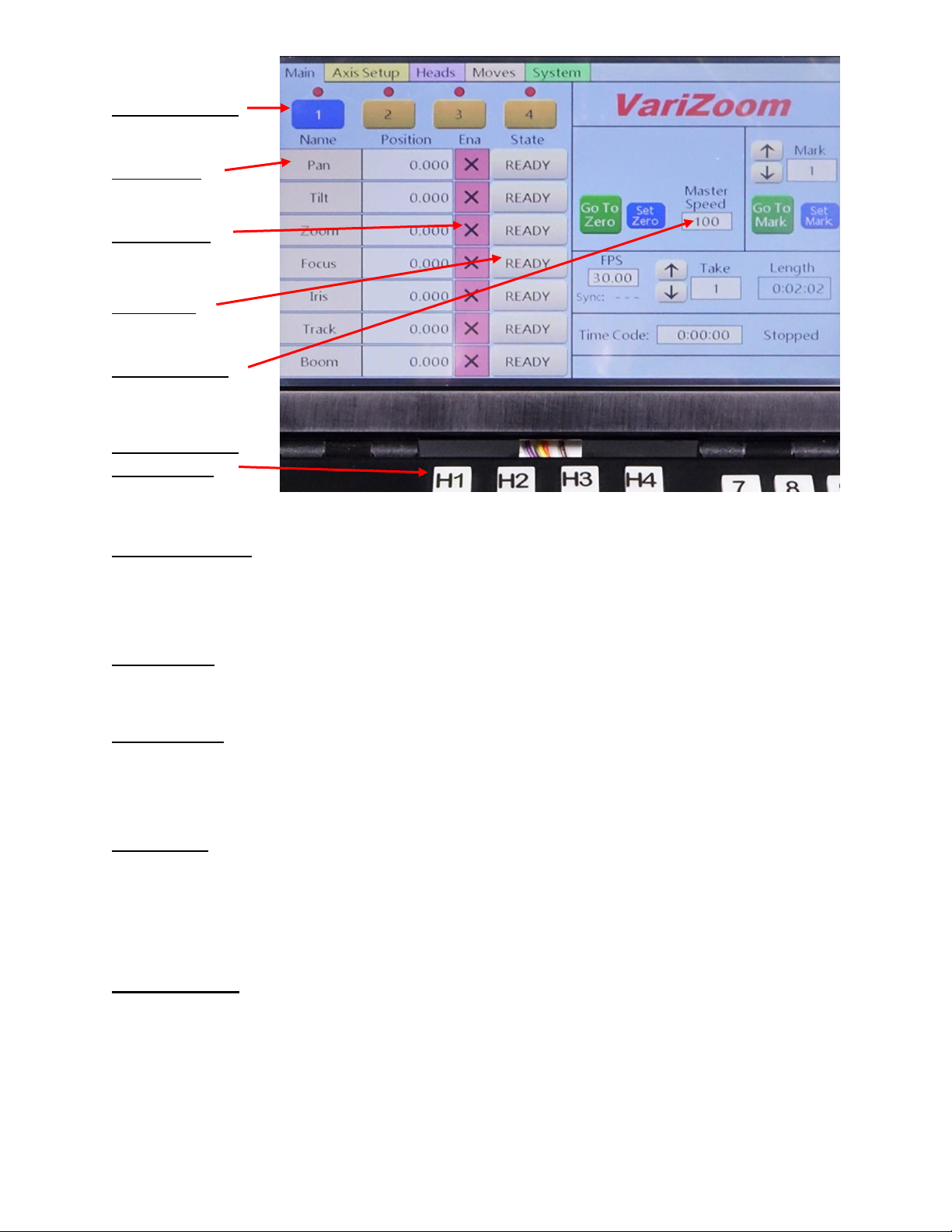
3
Head Selection:
Axis Setup:
Axis Enable:
Axis State:
Master Speed:
Head Selection
pushbuttons:
Head Selection: The light bubble above each touchscreen button 1-4 will be green if a
head is synced, red if not synced. You can also use the mechanical pushbuttons H1-H4
to change heads. Touch the onscreen buttons 1-4 to switch heads.
Axis Setup: Quickly access the setup screen for each individual axis to change speed,
smoothing and other parameters for only the selected axis. Touch the onscreen button.
Axis Enable: Green checkbox means the axis is enabled, while red checkbox means
the axis is disabled. On startup, the connected devices will be enabled by default
(green checkbox). Touch the onscreen button to enable/disable.
Axis State: The default state is “Ready,” and this is the desired state for live control of
the heads. The other available states are “Record” and “Playback” – you will not be
able to control the axis if it’s in “Playback” mode. For now, leave all axes in the
“Ready” state. Touch the onscreen button to change mode.
Master Speed: This is the global speed setting for all axes. You can change the
individual axis speeds under “Axis Setup,” but the Master Speed control will scale the
speeds of all axes up or down proportionally. Touch the onscreen button to adjust.
 Loading...